EP3139540B1 - Method for automated determination of optimal interconnect topologies of systems including service nodes, and associated processing device - Google Patents
Method for automated determination of optimal interconnect topologies of systems including service nodes, and associated processing device Download PDFInfo
- Publication number
- EP3139540B1 EP3139540B1 EP16185245.4A EP16185245A EP3139540B1 EP 3139540 B1 EP3139540 B1 EP 3139540B1 EP 16185245 A EP16185245 A EP 16185245A EP 3139540 B1 EP3139540 B1 EP 3139540B1
- Authority
- EP
- European Patent Office
- Prior art keywords
- level
- router
- routers
- chosen
- links
- Prior art date
- Legal status (The legal status is an assumption and is not a legal conclusion. Google has not performed a legal analysis and makes no representation as to the accuracy of the status listed.)
- Active
Links
- 238000000034 method Methods 0.000 title claims description 22
- 238000004590 computer program Methods 0.000 claims description 3
- 238000005265 energy consumption Methods 0.000 claims description 2
- 238000005457 optimization Methods 0.000 description 10
- 230000006870 function Effects 0.000 description 7
- 239000013598 vector Substances 0.000 description 6
- 238000004364 calculation method Methods 0.000 description 5
- 230000000903 blocking effect Effects 0.000 description 3
- 238000010276 construction Methods 0.000 description 3
- 235000021183 entrée Nutrition 0.000 description 3
- 238000004422 calculation algorithm Methods 0.000 description 2
- 238000004513 sizing Methods 0.000 description 2
- 230000015556 catabolic process Effects 0.000 description 1
- 238000013500 data storage Methods 0.000 description 1
- 230000002950 deficient Effects 0.000 description 1
- 230000001934 delay Effects 0.000 description 1
- 238000011156 evaluation Methods 0.000 description 1
- 238000000926 separation method Methods 0.000 description 1
- 230000008646 thermal stress Effects 0.000 description 1
Images
Classifications
-
- H—ELECTRICITY
- H04—ELECTRIC COMMUNICATION TECHNIQUE
- H04L—TRANSMISSION OF DIGITAL INFORMATION, e.g. TELEGRAPHIC COMMUNICATION
- H04L41/00—Arrangements for maintenance, administration or management of data switching networks, e.g. of packet switching networks
- H04L41/12—Discovery or management of network topologies
-
- H—ELECTRICITY
- H04—ELECTRIC COMMUNICATION TECHNIQUE
- H04L—TRANSMISSION OF DIGITAL INFORMATION, e.g. TELEGRAPHIC COMMUNICATION
- H04L41/00—Arrangements for maintenance, administration or management of data switching networks, e.g. of packet switching networks
- H04L41/14—Network analysis or design
- H04L41/145—Network analysis or design involving simulating, designing, planning or modelling of a network
-
- H—ELECTRICITY
- H04—ELECTRIC COMMUNICATION TECHNIQUE
- H04L—TRANSMISSION OF DIGITAL INFORMATION, e.g. TELEGRAPHIC COMMUNICATION
- H04L49/00—Packet switching elements
- H04L49/15—Interconnection of switching modules
-
- H—ELECTRICITY
- H04—ELECTRIC COMMUNICATION TECHNIQUE
- H04L—TRANSMISSION OF DIGITAL INFORMATION, e.g. TELEGRAPHIC COMMUNICATION
- H04L41/00—Arrangements for maintenance, administration or management of data switching networks, e.g. of packet switching networks
- H04L41/14—Network analysis or design
- H04L41/142—Network analysis or design using statistical or mathematical methods
Definitions
- the invention relates to systems comprising service nodes interconnected via links, and more specifically the determination of interconnection topologies of such systems.
- service node is understood to mean electronic equipment comprising resources that can be of any type provided that they provide at least one configurable service that is useful for the system to which they belong or for an application running in this system. Therefore, it may for example be a computing device comprising at least one processor, or an input / output equipment, or a router (or “switch”), or means of data storage.
- interconnection topology is understood to mean the architecture (or the interconnection network) defining the entirety of the links (or interconnections) between all the service nodes of a system. It is an undirected graph where vertices represent, for example, routers and arcs represent links (or cables). Note that there are several topology structures, including those called hierarchical, those in ring (direct topology), and those to mesh. Hierarchical structures include Fat Tree, Generalized Fat Tree (GFT), Extended Generalized Fat Tree (or XGFT), and Parallel Generalized Fat Tree (PGFT). . Among the mesh structures, there may be mentioned that called in English "HyperX”.
- a system may be in particular a type of computer called “high performance” (or supercomputer), or a data center (or “data center”).
- the determination (or sizing) of the interconnection topology of a system is a complex task because of the many constraints that must be taken into account, including the level of performance, cost, technical feasibility, logistical constraints (including congestion), and thermal constraints.
- This tool is adapted to Fat Tree type structures, and allows to choose the number of compute nodes as well as the type of router to use on the first two levels of the interconnection topology, and the blocking factor.
- the main disadvantage of this tool lies in the fact that it only provides the number of routers and links needed to set up the system, and therefore gives no information on the topological configuration (as a formal description, for example ), which is however essential to the evaluation of the quality of the topology in terms of routing and quality / price ratio.
- the invention is therefore particularly intended to improve the situation.
- the invention also proposes a computer program product comprising a set of instructions which, when executed by processing means, is suitable for implementing a method of the type presented above for determining a topology. optimum interconnection of a system comprising service nodes interconnected via links and constituting for some routers having ports and belonging to at least one level.
- the invention also proposes a processing device, intended to determine an optimal interconnection topology of a system comprising service nodes interconnected to one another via links and constituting for some routers having ports and belonging to at least one level. , and suitable for equipping electronic equipment comprising computing resources and a man / machine interface.
- the invention also proposes electronic equipment comprising calculation resources, a man / machine interface, and a processing device of the type of that presented above.
- the object of the invention is notably to propose a determination method, and an associated processing device DT, intended to allow the determination of an optimal interconnection topology of a system S comprising service nodes N ij .
- system S is a high performance computer (or supercomputer). But the invention is not limited to this type of system. It concerns any system comprising service nodes interconnected via links and constituting for some routers having ports and belonging to at least one level, and in particular the data centers (or data centers).
- the invention proposes a method for enabling the determination of an optimal interconnection topology of a system S (in this case a supercomputer) comprising service nodes N ij interconnected via links and constituting for each other some of the routers having ports and belonging to at least one level.
- This method comprises first and second steps, respectively referenced 10 and 20 in the exemplary algorithm of the figure 2 , and can be implemented by a processing device DT according to the invention.
- a processing device DT comprises at least one programming interface INP and resolution means MR.
- the programming interface INP can be of type API ("Application Programming Interface").
- it can be made from a python library, such as the one called Pyomo. It is recalled that Pyomo is a python library that can generate, in a particular format (.nl) supported by many equation solving programs, systems of equations previously declared and instantiated using an API.
- the processing device DT is installed in EE electronic equipment arranged in the form of a computer and therefore having in particular an IH man / machine interface (here a keyboard and a display screen) and RC calculation resources .
- the processing device DT could indeed be an electronic equipment having an IH man / machine interface and RC calculation resources.
- it could be a laptop or an electronic tablet, for example.
- the processing device DT could be installed in an electronic equipment EE arranged in a form other than a computer, and especially in the form of a laptop or an electronic tablet. .
- the processing device DT can be realized either in the form of software modules (or computer, or "software”); we are in the presence of a product computer program comprising a set of instructions which, when executed by processing means such as electronic circuits (or “hardware”), is adapted to implement the determination method, either in the form of a combination of software modules and electronic circuits.
- one begins by choosing from among a set of structures each defined by at least one structural constraint, and by means of the interface man / IH machine, a structure for an optimal interconnection topology to be determined for a system S.
- the set of structures is provided by the programming interface INP of the processing device DT.
- this set may include at least one hierarchical structure (such as Fat tree or Generalized Fat Tree (or GFT) or Extended Generalized Fat Tree (or XGFT) or Parallel Generalized Fat Tree (or PGFT)) and / or or at least one ring structure and / or a mesh structure (such as for example HyperX).
- GFT Generalized Fat Tree
- XGFT Extended Generalized Fat Tree
- PGFT Parallel Generalized Fat Tree
- the hierarchical structures can each be defined by at least one structural constraint that is a function of at least two variables mi and wi, and sometimes also a third variable pi, where the index i indexes the level to which a router belongs.
- m i is the number of service nodes N i-1j of a level i-1 connected to the same router N ij of a level i.
- w i is the number of routers N ij of a level i connected to the same service node N i-1j of a level i-1.
- pi is the number of links (or links) between a router N ij of a level i and a service node N i-1j of a level i -1.
- a GFT Generalized Fat Tree
- m and w vectors of dimension equal to one
- h vectors of dimension equal to one
- each level i router N ij is connected to m service nodes N i-1j of the lower level i-1
- each N i-1j router level i-1 is connected to w routers N ij of the upper level i. It can therefore be noted (h, m, w).
- An XGFT Extended Generalized Fat Tree
- m and w vectors of dimension equal to h
- h vectors of dimension equal to h
- links number of uplinks / downlinks
- a PGFT Parallel Generalized Fat Tree
- p is an XGFT to which the third vector p is added. It can therefore be noted (h, [m 1 , m 2 , ..., m h] , [w 1 , w 2 , ..., w h ], [p 1 , p 2 , ..., p h ]). It introduces the concept of redundancy of links between two service nodes of two neighboring levels.
- each topology parameter from a list of topology parameters provided by the programming interface INP.
- This list may, for example, be stored in storage means MS of the processing device DT.
- These storage means MS may, for example, be in the form of a memory, possibly of software type.
- the invention therefore proposes to define in an unambiguous manner the structure of each interconnection topology from one or more structural constraints (each defined as a function of at least one variable), because of the regularity of the topologies of theoretical interconnection. It should be noted that these structural constraints, and thus the structures of the interconnection topologies, can even be expressed as mathematical equations, as indicated below.
- the optimum interconnection topology of the system S is determined by means of a solver (defined by the resolution means MR), as a function of at least each structural constraint. corresponding and each topology parameter chosen in the first step (10) and at least one selected optimization criterion.
- each optimization criterion can, for example, be carried out by the user in the first step 10. Alternatively, it can be done in the second step 20. This choice can be made by means of the interface man / IH machine from a list of optimization criteria provided by the INP programming interface. This list may, for example, be stored in the storage means MS of the processing device DT.
- each interconnection topology By defining the structure of each interconnection topology from at least one structural constraint that is a function of at least one variable, it is now possible to determine the optimal interconnection topology of an S system by resolution of a optimization problem by means of a solver (or MR resolution means).
- a solver or MR resolution means.
- the separation between the modeling of the structure and the resolution method makes it possible to delegate the search for optimal solutions to a reliable and robust mathematical tool (or solver).
- solver called “Bonmin”, which is capable of solving systems of nonlinear equations with integer variables. It allows to find precise solutions in reduced times (typically a few seconds for topologies of 64000 nodes of service). In a variant, it is possible, for example, to use the Ipopt solver.
- each optimization criterion can be chosen from at least the cost of the system S, the desired level of performance of the system S (for example its computing power or its speed of calculation), the extensibility of the system S, the desired energy consumption of the system S, thermal stresses, in particular related to the reception environment of the system S, and the congestion of the system S (logistic criterion).
- an optimization criterion can be any property an interconnection topology.
- the optimal interconnect topology can be determined based also on at least one selected usage constraint.
- the user of the electronic equipment EE can choose, by means of the human / machine interface IH, each usage constraint from a list of usage constraints provided by the programming interface INP.
- This list may, for example, be stored in the storage means MS of the processing device DT.
- level 1 For the construction of the first level of routers N 1j , we use the value of mi. In this example, m 1 is 4 and therefore routers N 2j of second level will be connected to four routers sheets N 1j different from the first level. Then we use the value of wi. In this example, w 1 is 2 and therefore each leaf router N 1j of the first level is connected to two routers N 2j of the second level. Then we use the value of pi. In this example, pi is 1 and so we use a single (non-redundant) link between the first and second levels.
- the system includes two level 1 islands.
- m 2 is 2 and therefore the routers N 3j of the third level will be connected to two routers N 2j of two different islands of level 2.
- w 2 is 2 and therefore each router N 2j of the second level will be connected to two different routers N 3j belonging to the third level (and more precisely to different level 2 islands). Since each level 1 island has two routers N 2j of the second level, there are therefore two routers N 3j in each island of level 2.
- each link between routers of the second and third levels is doubled.
- the link between each computation node N 0j and the corresponding router N 1j is simple so as not to exceed the number of ports available on this router N 1j .
- This construction method can be implemented by the solver (or resolution means MR) for the system S of the figure 3 , with all the structural constraints and all the constraints of use described above, but also with the cost of the system S like criterion of optimization.
- the invention is not limited to the embodiments of the determination method, the processing device, and the electronic equipment described above, only by way of example, but it encompasses all the variants which the man can envisage. of art in the sole context of the claims below.
Description
L'invention concerne les systèmes comprenant des noeuds de service interconnectés entre eux via des liaisons, et plus précisément la détermination de topologies d'interconnexion de tels systèmes.The invention relates to systems comprising service nodes interconnected via links, and more specifically the determination of interconnection topologies of such systems.
On entend ici par « noeud de service » un équipement électronique comprenant des ressources pouvant être de tout type dès lors qu'elles assurent au moins un service configurable utile au système auquel elles appartiennent ou à une application tournant dans ce système. Par conséquent, il pourra par exemple s'agir d'un équipement de calcul comprenant au moins un processeur, ou d'un équipement d'entrée/sortie, ou d'un routeur (ou « switch »), ou encore de moyens de stockage de données.Here, the term "service node" is understood to mean electronic equipment comprising resources that can be of any type provided that they provide at least one configurable service that is useful for the system to which they belong or for an application running in this system. Therefore, it may for example be a computing device comprising at least one processor, or an input / output equipment, or a router (or "switch"), or means of data storage.
Par ailleurs, on entend ici par « topologie d'interconnexion » l'architecture (ou le réseau d'interconnexion) définissant l'intégralité des liaisons (ou interconnexions) entre tous les noeuds de service d'un système. Il s'agit d'un graphe non orienté où les sommets représentent, par exemple, des routeurs et les arcs représentent les liaisons (ou câbles). On notera qu'il existe plusieurs structures de topologie, et notamment celles dites hiérarchiques, celles en anneau (à topologie directe), et celles à maillage. Parmi les structures hiérarchiques, on peut notamment citer celles appelées en anglais « Fat tree », « Generalized Fat Tree » (ou GFT), « Extended Generalized Fat Tree » (ou XGFT), et « Parallel Generalized Fat Tree » (ou PGFT). Parmi les structures à maillage, on peut notamment citer celle appelée en anglais « HyperX ».Furthermore, here "interconnection topology" is understood to mean the architecture (or the interconnection network) defining the entirety of the links (or interconnections) between all the service nodes of a system. It is an undirected graph where vertices represent, for example, routers and arcs represent links (or cables). Note that there are several topology structures, including those called hierarchical, those in ring (direct topology), and those to mesh. Hierarchical structures include Fat Tree, Generalized Fat Tree (GFT), Extended Generalized Fat Tree (or XGFT), and Parallel Generalized Fat Tree (PGFT). . Among the mesh structures, there may be mentioned that called in English "HyperX".
Compte tenu des deux définitions qui précèdent, un système pourra être notamment un calculateur de type dit « haute performance » (ou supercalculateur), ou un centre de données (ou « data center »).Given the two definitions above, a system may be in particular a type of computer called "high performance" (or supercomputer), or a data center (or "data center").
La détermination (ou le dimensionnement) de la topologie d'interconnexion d'un système, comme par exemple un supercalculateur, est une tâche complexe en raison des très nombreuses contraintes qui doivent être priseS en compte, et notamment le niveau de performance, le coût, la faisabilité technique, les contraintes logistiques (et notamment l'encombrement), et les contraintes thermiques.The determination (or sizing) of the interconnection topology of a system, such as a supercomputer, is a complex task because of the many constraints that must be taken into account, including the level of performance, cost, technical feasibility, logistical constraints (including congestion), and thermal constraints.
En raison de cette complexité, la détermination (ou le dimensionnement) de la topologie d'interconnexion d'un système est fréquemment réalisée à la main après que la structure de cette topologie d'interconnexion ait été choisie, ce qui induit plusieurs inconvénients. En effet, la topologie d'interconnexion déterminée est rarement optimale sur tous les plans, voire infaisable techniquement, et donc on est contraint de réaliser de nombreuses modifications qui induisent fréquemment un surcoût important et/ou d'éventuels retards de mise à disposition du client et/ou une éventuelle diminution du niveau de performance souhaité initialement. De la demande de brevet publiée sous la référence
L'invention a donc notamment pour but d'améliorer la situation.The invention is therefore particularly intended to improve the situation.
Elle propose notamment à cet effet un procédé, destiné à permettre la détermination d'une topologie d'interconnexion optimale d'un système comprenant des noeuds de service interconnectés entre eux via des liaisons et constituant pour certains des routeurs ayant des ports et appartenant à au moins un niveau.It proposes for this purpose a method, intended to allow the determination of an optimal interconnection topology of a system comprising service nodes interconnected to each other via links and constituting for some routers having ports and belonging to the less a level.
Ce procédé se caractérise par le fait qu'il comprend :
- une première étape dans laquelle on choisit une structure pour une topologie d'interconnexion optimale à déterminer parmi un ensemble de structures définies chacune par au moins une contrainte structurelle, puis on choisit au moins un paramètre de topologie parmi un nombre maximal de ports des routeurs, un nombre de niveaux de routeurs, un nombre de noeuds de service connectés à un routeur appartenant au premier niveau, un nombre de noeuds de service d'un niveau i-1 connectés à un même routeur d'un niveau i, un nombre de routeurs d'un niveau i connectés à un même noeud de service d'un niveau i-1, un nombre de liaisons (ou liens) entre un routeur d'un niveau i et un noeud de service d'un niveau i -1, et
- une seconde étape dans laquelle on détermine au moyen d'un solveur la topologie d'interconnexion optimale en fonction d'au moins chaque contrainte structurelle correspondante et chaque paramètre de topologie choisi et d'au moins un critère d'optimisation choisi.
- a first step in which we choose a structure for a optimal interconnection topology to be determined from among a set of structures each defined by at least one structural constraint, then selecting at least one topology parameter from a maximum number of router ports, a number of router levels, a number of nodes of service nodes connected to a router belonging to the first level, a number of service nodes of a level i-1 connected to the same router of a level i, a number of routers of a level i connected to the same node of service of an i-1 level, a number of links (or links) between a router of a level i and a service node of a level i -1, and
- a second step in which the optimal interconnection topology is determined by means of a solver as a function of at least each corresponding structural constraint and each selected topology parameter and at least one chosen optimization criterion.
Ainsi, on peut désormais déterminer des topologies d'interconnexion optimales de différentes structures, et faisables techniquement, c'est-à-dire correspondant aux demandes des clients sans nécessiter de nombreuses modifications lors de leur mise en place.Thus, we can now determine optimal interconnection topologies of different structures, and technically feasible, that is to say corresponding to customer requests without requiring many changes during their implementation.
Le procédé selon l'invention peut comporter d'autres caractéristiques qui peuvent être prises séparément ou en combinaison, et notamment :
- chaque critère d'optimisation peut être choisi parmi (au moins) un coût du système, un niveau de performance, une extensibilité du système, une consommation d'énergie du système, des contraintes thermiques, et un encombrement du système ;
- chaque contrainte structurelle peut être choisie parmi (au moins) les inéquations suivantes : pi*mi + pi+1*Wi+1 ≤ radixMax, ph*mh ≤ radixMax, et w1*p1 + noeudsParFeuille ≤ radixMax, où mi est le nombre de noeuds de service d'un niveau i-1 connectés à un même routeur d'un niveau i, wi est le nombre de routeurs d'un niveau i connectés à un même noeud de service d'un niveau i-1, pi est le nombre de liaisons (ou liens) entre un routeur d'un niveau i et un noeud de service d'un niveau i -1, radixMax est le nombre maximal de ports de chaque routeur, h est le nombre de niveaux de routeurs, et noeudsParFeuille est le nombre de noeuds de service connectés à un même routeur appartenant au premier niveau ;
- dans la seconde étape on peut déterminer la topologie d'interconnexion optimale en fonction également d'au moins une contrainte d'utilisation choisie ;
- chaque contrainte d'utilisation peut être choisie parmi (au moins) une interdiction de connecter à un routeur appartenant à un niveau i donné plus de liaisons (ou liens) vers le niveau supérieur à ce niveau donné que de liaisons (ou liens) vers le niveau inférieur à ce niveau donné, une conservation d'une bande passante en entrée et en sortie de chaque routeur, une non conservation d'une bande passante en entrée et en sortie de chaque routeur, un nombre minimum de noeuds de service, un nombre maximum de liaisons (ou liens) entre deux routeurs ;

-
- le système peut être choisi parmi (au moins) un supercalculateur et un centre de données (ou « data center »).
- each optimization criterion may be selected from (at least) a system cost, a performance level, a system extensibility, a system power consumption, thermal constraints, and a system footprint;
- each structural constraint can be chosen from (at least) the following inequalities: p i * m i + p i + 1 * W i + 1 ≤ radixMax, p h * m h ≤ radixMax, and w 1 * p 1 + nodesParSheet ≤ radixMax, where mi is the number of service nodes of a level i-1 connected to the same router of a level i, w i is the number of routers of a level i connected to the same service node of a level i-1, pi is the number of links (or links) between a router of a level i and a service node of a level i -1, radixMax is the maximum number of ports of each router, h is the number of levels of routers, and nodesParFeuille is the number of service nodes connected to the same router belonging to the first level;
- in the second step, the optimal interconnection topology can be determined as a function also of at least one chosen utilization constraint;
- each usage constraint can be chosen among (at least) a prohibition to connect to a router belonging to a level i given more links (or links) to the level higher than this level given that links (or links) to the below this level, a bandwidth conservation input and output of each router, a non-conservation bandwidth input and output of each router, a minimum number of service nodes, a number maximum number of links (or links) between two routers;
-
- the system can be selected from (at least) a supercomputer and a data center (or "data center").
L'invention propose également un produit programme d'ordinateur comprenant un jeu d'instructions qui, lorsqu'il est exécuté par des moyens de traitement, est propre à mettre en oeuvre un procédé du type de celui présenté ci-avant pour déterminer une topologie d'interconnexion optimale d'un système comprenant des noeuds de service interconnectés entre eux via des liaisons et constituant pour certains des routeurs ayant des ports et appartenant à au moins un niveau.The invention also proposes a computer program product comprising a set of instructions which, when executed by processing means, is suitable for implementing a method of the type presented above for determining a topology. optimum interconnection of a system comprising service nodes interconnected via links and constituting for some routers having ports and belonging to at least one level.
L'invention propose également un dispositif de traitement, destiné à déterminer une topologie d'interconnexion optimale d'un système comprenant des noeuds de service interconnectés entre eux via des liaisons et constituant pour certains des routeurs ayant des ports et appartenant à au moins un niveau, et propre à équiper un équipement électronique comprenant des ressources de calcul et une interface homme/machine.The invention also proposes a processing device, intended to determine an optimal interconnection topology of a system comprising service nodes interconnected to one another via links and constituting for some routers having ports and belonging to at least one level. , and suitable for equipping electronic equipment comprising computing resources and a man / machine interface.
Ce dispositif de traitement se caractérise par le fait qu'il comprend :
- une interface de programmation agencée pour permettre à un usager de choisir via l'interface homme/machine une structure pour une topologie d'interconnexion optimale à déterminer parmi un ensemble de structures définies chacune par au moins une contrainte structurelle, et au moins un paramètre de topologie choisi parmi un nombre maximal de ports des routeurs, un nombre de niveaux de routeurs, un nombre de noeuds de service connectés à un routeur appartenant au premier niveau, un nombre de noeuds de service d'un niveau i-1 connectés à un même routeur d'un niveau i, un nombre de routeurs d'un niveau i connectés à un même noeud de service d'un niveau i-1, un nombre de liaisons (ou liens) entre un routeur d'un niveau i et un noeud de service d'un niveau i -1, et
- des moyens de résolution agencés pour déterminer la topologie d'interconnexion optimale en fonction d'au moins chaque contrainte structurelle correspondante et chaque paramètre de topologie choisi et d'au moins un critère d'optimisation choisi.
- a programming interface arranged to allow a user to choose via the man / machine interface a structure for an optimal interconnection topology to be determined from among a set of structures each defined by at least one structural constraint, and at least one parameter of topology chosen from a maximum number of ports routers, a number of levels of routers, a number of nodes of service connected to a router belonging to the first level, a number of service nodes of a level i-1 connected to the same router of a level i, a number of routers of a level i connected to the same service node a level i-1, a number of links (or links) between a router of a level i and a service node of a level i -1, and
- resolution means arranged to determine the optimal interconnection topology as a function of at least each corresponding structural constraint and each selected topology parameter and at least one selected optimization criterion.
L'invention propose également un équipement électronique comprenant des ressources de calcul, une interface homme/machine, et un dispositif de traitement du type de celui présenté ci-avant.The invention also proposes electronic equipment comprising calculation resources, a man / machine interface, and a processing device of the type of that presented above.
D'autres caractéristiques et avantages de l'invention apparaîtront à l'examen de la description détaillée ci-après, et des dessins annexés, sur lesquels :
- la
figure 1 illustre de façon schématique et fonctionnelle un ordinateur équipé d'un exemple de réalisation d'un dispositif de traitement selon l'invention, - la
figure 2 illustre un exemple d'algorithme mettant en oeuvre un procédé de détermination selon l'invention, et - la
figure 3 illustre de façon schématique un exemple de topologie d'interconnexion optimisée, déterminé au moyen d'un procédé de détermination selon l'invention avec certains paramètres de topologie.
- the
figure 1 schematically and functionally illustrates a computer equipped with an exemplary embodiment of a treatment device according to the invention, - the
figure 2 illustrates an example of an algorithm implementing a determination method according to the invention, and - the
figure 3 schematically illustrates an exemplary optimized interconnection topology, determined by means of a determination method according to the invention with certain topology parameters.
L'invention a notamment pour objet de proposer un procédé de détermination, et un dispositif de traitement DT associé, destinés à permettre la détermination d'une topologie d'interconnexion optimale d'un système S comprenant des noeuds de service Nij.The object of the invention is notably to propose a determination method, and an associated processing device DT, intended to allow the determination of an optimal interconnection topology of a system S comprising service nodes N ij .
Dans ce qui suit, on considère, à titre d'exemple non limitatif, que le système S est un calculateur haute performance (ou supercalculateur). Mais l'invention n'est pas limitée à ce type de système. Elle concerne en effet tout système comprenant des noeuds de service interconnectés entre eux via des liaisons et constituant pour certains des routeurs ayant des ports et appartenant à au moins un niveau, et notamment les centres de données (ou data centers).In the following, we consider, by way of non-limiting example, that the system S is a high performance computer (or supercomputer). But the invention is not limited to this type of system. It concerns any system comprising service nodes interconnected via links and constituting for some routers having ports and belonging to at least one level, and in particular the data centers (or data centers).
Comme indiqué plus haut, l'invention propose un procédé destiné à permettre la détermination d'une topologie d'interconnexion optimale d'un système S (ici un supercalculateur) comprenant des noeuds de service Nij interconnectés entre eux via des liaisons et constituant pour certains des routeurs ayant des ports et appartenant à au moins un niveau.As indicated above, the invention proposes a method for enabling the determination of an optimal interconnection topology of a system S (in this case a supercomputer) comprising service nodes N ij interconnected via links and constituting for each other some of the routers having ports and belonging to at least one level.
Ce procédé comprend des première et seconde étapes, référencées respectivement 10 et 20 dans l'exemple d'algorithme de la
Comme illustré sur la
Par exemple, l'interface de programmation INP peut être de type API (« Application Programming Interface »). A titre d'exemple non limitatif, elle peut être réalisée à partir d'une librairie python, telle que celle appelée Pyomo. Il est rappelé que Pyomo est une librairie python permettant de générer, dans un format particulier (.nl) supporté par beaucoup de programmes de résolution d'équations, des systèmes d'équations préalablement déclarés et instanciés au moyen d'une API.For example, the programming interface INP can be of type API ("Application Programming Interface"). As a non-limiting example, it can be made from a python library, such as the one called Pyomo. It is recalled that Pyomo is a python library that can generate, in a particular format (.nl) supported by many equation solving programs, systems of equations previously declared and instantiated using an API.
Dans l'exemple non limitatif illustré sur la
Durant la première étape 10 du procédé selon l'invention, on (un usager de l'équipement électronique EE) commence par choisir, parmi un ensemble de structures définies chacune par au moins une contrainte structurelle, et au moyen de l'interface homme/machine IH, une structure pour une topologie d'interconnexion optimale devant être déterminée pour un système S. L'ensemble de structures est fourni par l'interface de programmation INP du dispositif de traitement DT. Par exemple, cet ensemble peut comprendre au moins une structure de type hiérarchique (comme par exemple Fat tree ou Generalized Fat Tree (ou GFT) ou Extended Generalized Fat Tree (ou XGFT) ou encore Parallel Generalized Fat Tree (ou PGFT)) et/ou au moins une structure en anneau et/ou une structure à maillage (comme par exemple HyperX).During the
Par exemple, les structures hiérarchiques peuvent être définies chacune par au moins une contrainte structurelle fonction d'au moins deux variables mi et wi, et parfois également d'une troisième variable pi, où l'indice i indexe le niveau auquel appartient un routeur au sein de la structure. mi est le nombre de noeuds de service Ni-1j d'un niveau i-1 connectés à un même routeur Nij d'un niveau i. wi est le nombre de routeurs Nij d'un niveau i connectés à un même noeud de service Ni-1j d'un niveau i-1. pi est le nombre de liaisons (ou liens) entre un routeur Nij d'un niveau i et un noeud de service Ni-1j d'un niveau i -1. Ces variables m, w et p sont des vecteurs de dimension h. Avec le choix fait ci-dessus pour l'indexage, la valeur i = 0 est attribuée au niveau contenant les noeuds de service N0j qui sont connectés à des routeurs N1j (dits feuilles) du premier niveau (i = 1).For example, the hierarchical structures can each be defined by at least one structural constraint that is a function of at least two variables mi and wi, and sometimes also a third variable pi, where the index i indexes the level to which a router belongs. within the structure. m i is the number of service nodes N i-1j of a level i-1 connected to the same router N ij of a level i. w i is the number of routers N ij of a level i connected to the same service node N i-1j of a level i-1. pi is the number of links (or links) between a router N ij of a level i and a service node N i-1j of a level i -1. These variables m, w and p are vectors of dimension h. With the choice made above for indexing, the value i = 0 is assigned to the level containing the service nodes N 0j which are connected to routers N 1j (called sheets) of the first level (i = 1).
Ainsi, un GFT (Generalized Fat Tree) peut être défini par au moins une contrainte structurelle fonction des deux variables m et w (vecteurs de dimension égale à un), ainsi que par h, où ∀i ∈ ![]()
![]()
![]()
![]()
Un XGFT (Extended Generalized Fat Tree) peut être défini par au moins une contrainte structurelle fonction des deux variables m et w (vecteurs de dimension égale à h), ainsi que par h, où ∀i ∈ ![]()
![]()
![]()
![]()
Un PGFT (Parallel Generalized Fat Tree) est un XGFT auquel on ajoute le troisième vecteur p. Il peut donc être noté (h,[m1, m2,...,mh],[w1, w2,...,wh],[p1, p2,...,ph]). Il permet d'introduire la notion de redondance de liens entre deux noeuds de service de deux niveaux voisins.A PGFT (Parallel Generalized Fat Tree) is an XGFT to which the third vector p is added. It can therefore be noted (h, [m 1 , m 2 , ..., m h] , [w 1 , w 2 , ..., w h ], [p 1 , p 2 , ..., p h ]). It introduces the concept of redundancy of links between two service nodes of two neighboring levels.
La première étape 10 se poursuit en choisissant au moins un paramètre de topologie parmi :
- un nombre maximal de ports des routeurs Nij (avec i ≥ 1),
- un nombre h de niveaux de routeurs Nij (avec i ≥ 1),
- un nombre de noeuds de service N0j connectés à un routeur N1j appartenant au premier niveau (i = 1),
- un nombre de routeurs Ni-1j d'un niveau i-1 connectés à un même routeur Nij d'un niveau i,
- un nombre de routeurs Nij d'un niveau i connectés à un même noeud de service Ni-1j d'un niveau i-1, et
- un nombre de liaisons (ou liens) entre un routeur Nij d'un niveau i et un noeud de service Ni-1j d'un niveau i -1.
- a maximum number of ports of routers N ij (with i ≥ 1),
- a number h of routers N ij levels (with i ≥ 1),
- a number of service nodes N 0j connected to a router N 1j belonging to the first level (i = 1),
- a number of routers N i-1j of a level i-1 connected to the same router N ij of a level i,
- a number of routers N ij of a level i connected to the same service node N i-1j of a level i-1, and
- a number of links (or links) between a router N ij of a level i and a service node N i-1j of a level i -1.
On notera que l'usager de l'équipement électronique EE peut choisir au moyen de l'interface homme/machine IH chaque paramètre de topologie parmi une liste de paramètres de topologie fournie par l'interface de programmation INP.It will be noted that the user of the electronic equipment EE can choose, by means of the human / machine interface IH, each topology parameter from a list of topology parameters provided by the programming interface INP.
Cette liste peut, par exemple, être stockée dans des moyens de stockage MS du dispositif de traitement DT. Ces moyens de stockage MS peuvent, par exemple, se présenter sous la forme d'une mémoire, éventuellement de type logiciel.This list may, for example, be stored in storage means MS of the processing device DT. These storage means MS may, for example, be in the form of a memory, possibly of software type.
L'invention propose donc de définir de façon non ambigüe la structure de chaque topologie d'interconnexion à partir d'une ou plusieurs contraintes structurelles (définies chacune en fonction d'au moins une variable), en raison de la régularité des topologies d'interconnexion théoriques. On notera que ces contraintes structurelles, et donc les structures des topologies d'interconnexion, peuvent même être exprimées sous forme d'équations mathématiques, comme indiqué ci-dessous.The invention therefore proposes to define in an unambiguous manner the structure of each interconnection topology from one or more structural constraints (each defined as a function of at least one variable), because of the regularity of the topologies of theoretical interconnection. It should be noted that these structural constraints, and thus the structures of the interconnection topologies, can even be expressed as mathematical equations, as indicated below.
A titre d'exemple pour les structures PGFT, chaque contrainte structurelle peut être choisie parmi les inéquations suivantes ∀i ∈ [1,h-1], où h est le nombre de niveaux de routeurs de la topologie d'interconnexion :
- pi*mi + pi+1*Wi+1 ≤ radixMax (cette contrainte structurelle permet de spécifier que le nombre de liaisons connectées à un routeur ne doit pas dépasser le nombre de ports disponibles sur ce routeur),
- ph*mh ≤ radixMax, et
- w1*p1 + noeudsParFeuille ≤ radixMax,
- p i * m i + p i + 1 * W i + 1 ≤ radixMax (this structural constraint makes it possible to specify that the number of links connected to a router must not exceed the number of available ports on this router),
- p h * m h ≤ radixMax, and
- w 1 * p 1 + nodesParSheet ≤ radixMax,
Egalement à titre d'exemple pour les structures XGFT, chaque contrainte structurelle peut être choisie parmi les inéquations suivantes ∀i ∈ [1,h-1], où h est le nombre de niveaux de routeurs de la topologie d'interconnexion :
- mi + wi+1 ≤ radixMax,
- mh ≤ radixMax, et
- wi + noeudsParFeuille ≤ radixMax.
- m i + w i + 1 ≤ radixMax,
- m h ≤ radixMax, and
- wi + nodesParSheet ≤ radixMax.
Egalement à titre d'exemple pour les structures GFT, chaque contrainte structurelle peut être choisie parmi les inéquations suivantes ∀i ∈ [1,h-1], où h est le nombre de niveaux de routeurs de la topologie d'interconnexion :
- m + w ≤ radixMax,
- m ≤ radixMax, et
- w + noeudsParFeuille ≤ radixMax.
- m + w ≤ radixMax,
- m ≤ radixMax, and
- w + nodesParSheet ≤ radixMax.
Durant la deuxième étape (20) du procédé selon l'invention, on détermine au moyen d'un solveur (défini par les moyens de résolution MR) la topologie d'interconnexion optimale du système S, en fonction d'au moins chaque contrainte structurelle correspondante et chaque paramètre de topologie choisi dans la première étape (10) et d'au moins un critère d'optimisation choisi.During the second step (20) of the method according to the invention, the optimum interconnection topology of the system S is determined by means of a solver (defined by the resolution means MR), as a function of at least each structural constraint. corresponding and each topology parameter chosen in the first step (10) and at least one selected optimization criterion.
Le choix de chaque critère d'optimisation peut, par exemple être effectué par l'usager dans la première étape 10. En variante, il peut se faire dans la seconde étape 20. Ce choix peut se faire au moyen de l'interface homme/machine IH parmi une liste de critères d'optimisation fournie par l'interface de programmation INP. Cette liste peut, par exemple, être stockée dans les moyens de stockage MS du dispositif de traitement DT.The choice of each optimization criterion can, for example, be carried out by the user in the
Grâce à la définition de la structure de chaque topologie d'interconnexion à partir d'au moins une contrainte structurelle fonction d'au moins une variable, on peut désormais déterminer la topologie d'interconnexion optimale d'un système S par résolution d'un problème d'optimisation au moyen d'un solveur (ou moyens de résolution MR). En d'autres termes, la séparation entre la modélisation de la structure et la méthode de résolution permet de déléguer la recherche de solutions optimales à un outil mathématique (ou solveur) fiable et robuste.By defining the structure of each interconnection topology from at least one structural constraint that is a function of at least one variable, it is now possible to determine the optimal interconnection topology of an S system by resolution of a optimization problem by means of a solver (or MR resolution means). In other words, the separation between the modeling of the structure and the resolution method makes it possible to delegate the search for optimal solutions to a reliable and robust mathematical tool (or solver).
A titre d'exemple non limitatif, on peut utiliser le solveur appelé « Bonmin », lequel est capable de résoudre des systèmes d'équations non-linéaires à variables entières. Il permet de trouver des solutions précises en des temps réduits (typiquement quelques secondes pour des topologies de 64000 noeuds de service). En variante, on peut, par exemple, utiliser le solveur Ipopt.By way of nonlimiting example, one can use the solver called "Bonmin", which is capable of solving systems of nonlinear equations with integer variables. It allows to find precise solutions in reduced times (typically a few seconds for topologies of 64000 nodes of service). In a variant, it is possible, for example, to use the Ipopt solver.
Par exemple, chaque critère d'optimisation peut être choisi parmi au moins le coût du système S, le niveau de performance souhaité du système S (par exemple sa puissance de calcul ou sa rapidité de calcul), l'extensibilité du système S, la consommation d'énergie souhaitée du système S, des contraintes thermiques, notamment liées à l'environnement d'accueil du système S, et l'encombrement du système S (critère logistique). D'une manière générale un critère d'optimisation peut être n'importe quelle propriété d'une topologie d'interconnexion.For example, each optimization criterion can be chosen from at least the cost of the system S, the desired level of performance of the system S (for example its computing power or its speed of calculation), the extensibility of the system S, the desired energy consumption of the system S, thermal stresses, in particular related to the reception environment of the system S, and the congestion of the system S (logistic criterion). In general, an optimization criterion can be any property an interconnection topology.
On notera que dans certaines situations l'utilisation des seules contraintes structurelles peut aboutir à une topologie d'interconnexion juste mais non utilisable dans la pratique. Par conséquent, dans la seconde étape 20, on peut déterminer la topologie d'interconnexion optimale en fonction également d'au moins une contrainte d'utilisation choisie.It should be noted that in certain situations the use of the only structural constraints can lead to a connection topology that is right but not usable in practice. Therefore, in the
Par exemple, chaque contrainte d'utilisation peut être choisie parmi au moins :
- une interdiction de connecter à un routeur Nij (avec i > 1) appartenant à un niveau i donné plus de liaisons (ou liens) vers le niveau supérieur à ce niveau donné que de liaisons (ou liens) vers le niveau inférieur à ce niveau donné (en effet les liaisons inférieures ne pourront pas générer suffisamment de trafic pour que toutes les liaisons supérieures soient utilisées). Avec les exemples de définition des variables m, w, p et h donnés plus haut, cette contrainte d'utilisation peut s'exprimer sous forme mathématique au moyen de l'inéquation wi+1 ≤ mi,
- une conservation d'une bande passante en entrée et en sortie de chaque routeur Nij (avec i > 1). Avec les exemples de définition des variables m, w, p et h donnés plus haut, cette contrainte d'utilisation peut s'exprimer sous forme mathématique au moyen de l'équation facteursMini = facteursMaxi = 1, où facteursMini et facteursMaxi sont des facteurs de blocage minimal et maximal pour le niveau i considéré (un facteur de blocage étant un rapport de nombres de noeuds de service entre un niveau supérieur à un niveau i donné et un niveau inférieur à ce niveau i donné). Par exemple, on peut utiliser les inéquations facteursMini ≤ pi+1*wi+1/pi*mi ≤ facteursMaxi et facteursMin1 ≤ p1*w1/noeudsParFeuille ≤ facteursMax1. Dans ce cas, si on n'a que des composantes égales à 1 pour facteursMini et facteursMaxi, on a 1 ≤ p1*w1/noeudsParFeuille ≤ 1 (pour le niveau 1, et la même chose pour les autres niveaux), et donc il y a conservation de la bande passante. En revanche, si on a par exemple pour le niveau 1 facteursMin1 = 0,5 et facteursMax1 =1, on autorise jusqu'à une liaison montante pour deux descendantes, et donc il n'y a pas conservation de la bande passante. On notera que l'on pourrait ici utiliser d'autres formules, comme par exemple facteursMini = 1 et facteursMaxi = 1 pour tous les i ou pi+1 * wi+1 = pi * mi,
- un nombre minimum de noeuds de service Nij. Avec les exemples de définition des variables m, h et noeudsParFeuille donnés plus haut, cette contrainte d'utilisation peut s'exprimer sous forme mathématique au moyen de l'inéquation noeudsParFeuille*Πmi (de i = 1 à h) ≥ minNoeuds, où minNoeuds est le nombre de noeuds de service N0j connectés à des routeurs feuilles N1j du premier niveau (i = 1), et
- un nombre maximum de liaisons (ou liens) entre deux routeurs Nij. Cette contrainte d'utilisation permet d'éviter d'introduire une baisse de la tolérance aux pannes si un routeur est défectueux. Avec l'exemple de définition de la variable p donné plus haut, cette contrainte d'utilisation peut s'exprimer sous forme mathématique au moyen de l'inéquation 1 ≤ pi ≤ maxRépétition, où maxRépétition est le nombre maximum de liaisons entre deux routeurs.
- a prohibition to connect to a router N ij (with i> 1) belonging to a given level i gives more links (or links) to the level above this level than links (or links) to the level below this level given (indeed the lower links will not be able to generate enough traffic for all the higher links to be used). With the examples of definition of the variables m, w, p and h given above, this utilization constraint can be expressed in mathematical form by means of the inequation w i + 1 ≤ m i ,
- a bandwidth conservation input and output of each router N ij (with i> 1). With the examples of definition of the variables m, w, p and h given above, this utilization constraint can be expressed in mathematical form by means of the equation factorsMini = factorsMaxi = 1, where factorsMini and factors Maxi are factors of minimum and maximum blocking for the level i considered (a blocking factor being a ratio of numbers of service nodes between a level above a given level i and a level below this level i given). For example, it is possible to use the factor equations Mini ≤ p i + 1 * w i + 1 / p i * m i ≤ factorsMax i and factorsMin 1 ≤ p 1 * w 1 / nodesParSheet ≤ factorMax 1 . In this case, if we only have components equal to 1 and facteursMini facteursMax i was 1 ≤ p 1 * w 1 / noeudsParFeuille ≤ 1 (at level 1, and the same for the other levels), and so there is conservation of the bandwidth. On the other hand, if one has for example for the level 1 factorsMin 1 = 0,5 and factorsMax 1 = 1, one authorizes up to one uplink for two descendants, and thus there is not conservation of the bandwidth. Note that we could use other formulas here, for example factorsMin i = 1 and factorsMaxi = 1 for all i or p i + 1 * w i + 1 = p i * m i ,
- a minimum number of service nodes N ij . With the examples of definition of the variables m, h and nodeSheet given above, this usage constraint can be expressed in mathematical form by means of the inequation nodesParFeuille * Πm i (from i = 1 to h) ≥ minNodes, where minNodes is the number of N 0j service nodes connected to leaf routers N 1j of the first level (i = 1), and
- a maximum number of links (or links) between two routers N ij . This usage constraint makes it possible to avoid introducing a decrease in fault tolerance if a router is defective. With the example of the definition of the variable p given above, this usage constraint can be expressed in mathematical form by means of the inequation 1 ≤ p i ≤ maxRepeat, where maxRepetition is the maximum number of links between two routers .
On notera qu'il est également possible d'utiliser des contraintes d'utilisation spécifiques pour écarter certains cas particuliers. C'est notamment le cas lorsque l'une des composantes du vecteur m et/ou l'une des composantes du vecteur w est égale à 1. En effet, dans ce cas il est possible de construire une structure PGFT similaire en supprimant un niveau (pour un prix inférieur et tout aussi résistant aux pannes). Dans ce cas, on peut utiliser une contrainte d'utilisation qui s'exprime sous forme mathématique au moyen des inéquations wi+1 > 1 et mi > 1.Note that it is also possible to use specific usage constraints to rule out particular cases. This is particularly the case when one of the components of the vector m and / or one of the components of the vector w is equal to 1. Indeed, in this case it is possible to build a similar PGFT structure by deleting a level (for a lower price and just as resistant to breakdowns). In this case, a utilization constraint can be used that is expressed in mathematical form using the inequalities w i + 1 > 1 and mi> 1.
On notera également que l'usager de l'équipement électronique EE peut choisir au moyen de l'interface homme/machine IH chaque contrainte d'utilisation parmi une liste de contraintes d'utilisation fournie par l'interface de programmation INP. Cette liste peut, par exemple, être stockée dans les moyens de stockage MS du dispositif de traitement DT.It will also be noted that the user of the electronic equipment EE can choose, by means of the human / machine interface IH, each usage constraint from a list of usage constraints provided by the programming interface INP. This list may, for example, be stored in the storage means MS of the processing device DT.
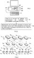
On a schématiquement illustré sur la
Pour la construction du premier niveau de routeurs N1j, on utilise la valeur de mi. Dans cet exemple, m1 vaut 4 et donc les routeurs N2j du deuxième niveau seront reliés à quatre routeurs feuilles N1j différents du premier niveau. Puis, on utilise la valeur de wi. Dans cet exemple, w1 vaut 2 et donc chaque routeur feuille N1j du premier niveau est relié à deux routeurs N2j du deuxième niveau. Puis, on utilise la valeur de pi. Dans cet exemple, pi vaut 1 et donc on utilise une unique liaison (non redondante) entre les premier et deuxième niveaux. On appelle ci-après ilot de niveau 1 un groupe comprenant quatre routeurs N1j (j = 1 à 4) du premier niveau et deux routeurs N2j (j = 1 à 2) du deuxième niveau. Dans cet exemple, le système comprend deux ilots de niveau 1.For the construction of the first level of routers N 1j , we use the value of mi. In this example, m 1 is 4 and therefore routers N 2j of second level will be connected to four routers sheets N 1j different from the first level. Then we use the value of wi. In this example, w 1 is 2 and therefore each leaf router N 1j of the first level is connected to two routers N 2j of the second level. Then we use the value of pi. In this example, pi is 1 and so we use a single (non-redundant) link between the first and second levels. Hereinafter level 1 is called a group comprising four routers N 1j (j = 1 to 4) of the first level and two routers N 2j (j = 1 to 2) of the second level. In this example, the system includes two level 1 islands.
Ensuite, on utilise la valeur de m2. Dans cet exemple, m2 vaut 2 et donc les routeurs N3j du troisième niveau seront reliés à deux routeurs N2j de deux ilots différents du niveau 2. Puis, on utilise la valeur de w2. Dans cet exemple, w2 vaut 2 et donc chaque routeur N2j du deuxième niveau sera relié à deux routeurs N3j différents appartenant au troisième niveau (et plus précisément à des ilots de niveau 2 différents). Chaque ilot de niveau 1 ayant deux routeurs N2j du deuxième niveau, on a donc deux routeurs N3j dans chaque îlot de niveau 2.Then we use the value of m 2 . In this example, m 2 is 2 and therefore the routers N 3j of the third level will be connected to two routers N 2j of two different islands of level 2. Then, we use the value of w 2 . In this example, w 2 is 2 and therefore each router N 2j of the second level will be connected to two different routers N 3j belonging to the third level (and more precisely to different level 2 islands). Since each level 1 island has two routers N 2j of the second level, there are therefore two routers N 3j in each island of level 2.
Ensuite, on complète les liaisons manquantes entre les deuxième et troisième niveaux, puis, la valeur de p2 étant égale à 2, on double chaque liaison entre routeurs des deuxième et troisième niveaux. Enfin, dans le cas d'un supercalculateur S on ajoute des noeuds de calcul N0j en les connectant aux routeurs N1j du premier niveau. Ici, la liaison entre chaque noeud de calcul N0j et le routeur N1j correspondant est simple pour ne pas dépasser le nombre de ports disponibles sur ce routeur N1j.Then, the missing links between the second and third levels are completed, then, the value of p 2 being equal to 2, each link between routers of the second and third levels is doubled. Finally, in the case of a supercomputer S N 0j calculation nodes are added by connecting them to routers N 1j of the first level. Here, the link between each computation node N 0j and the corresponding router N 1j is simple so as not to exceed the number of ports available on this router N 1j .
Cette méthode de construction peut être mise en oeuvre par le solveur (ou moyens de résolution MR) pour le système S de la
L'invention ne se limite pas aux modes de réalisation de procédé de détermination, de dispositif de traitement, et d'équipement électronique décrits ci-avant, seulement à titre d'exemple, mais elle englobe toutes les variantes que pourra envisager l'homme de l'art dans le seul cadre des revendications ci-après.The invention is not limited to the embodiments of the determination method, the processing device, and the electronic equipment described above, only by way of example, but it encompasses all the variants which the man can envisage. of art in the sole context of the claims below.
Claims (9)
- Method for determining an optimal interconnection topology of a system (S) including service nodes (Nij) interconnected using links some of which are routers with ports, and belonging to at least one level, characterised in that it includes at least one step (10) in which a structure is chosen for an optimal interconnection topology to be determined from among a set of structures each defined by at least one structural constraint, and at least one topology parameter is then chosen from among a maximum number of ports of the routers, a number of levels of routers, a number of service nodes (Nij) connected to a router belonging to the first level and called hereinafter a "leaf router", a number of service nodes of a level i-1 connected to a given router of a level i, a number of routers of a level i connected to a given service node of a level i-1, a number of links between a router of a level i and a service node (Ni-1j) of a level i -1, and a second step (20) in which one determines by means of a solver the said optimal interconnection topology defined by at least one corresponding structural constraint and each chosen topology parameter and at least one chosen optimisation criterion.
- Method according to claim 1, characterised in that each optimisation criterion is chosen from a group including the cost of the said system (S), a level of performance of the said system (S), the extensibility of the said system (S), the energy consumption of the said system (S), thermal constraints, and the encumbrance of the said system (S).
- Method according to one of claims 1 and 2, characterised in that each structural constraint is chosen from a group of inequalities including pi*mi + pi+1*wi+1 ≥ radixMax, ph*mh ≥ radixMax, and w1*p1 + noeudsParFeuille ≥ radixMax, where mi is the number of service nodes of a level i-1 connected to given router of a level i, wi is the number of routers of a level i connected to given service node of a level i-1, pi is the number of links between a router of a level i and a service node (Ni-1j) of a level i - 1, radixMax is the maximum number of ports of each router, h is the number of levels of routers, and noeudsParFeuille is the number of service nodes (N0j) connected to a given router (N1j) belonging to the said first level.
- Method according to one of claims 1 to 3, characterised in that in the said second step (20) the said optimal interconnection topology is also determined in terms of at least one chosen usage constraint.
- Method according to claim 4, characterised in that each usage constraint is chosen from a group including a prohibition against connecting to a router belonging to a given level i more links to the level above the said given level than links to the level below this said given level, conservation of an input and output bandwidth of each router, non-conservation of an input and output bandwidth of each router, a minimum number of service nodes (Nij), and a maximum number of links between two routers.
- Method according to one of claims 1 to 5, characterised in that the said system (S) is chosen from a group including a supercomputer and a data centre.
- Computer program product including a set of instructions which, when it is executed by processing means, is able to implement a method according to one of the previous claims to determine an optimal interconnection topology of a system (S) including service nodes (Nij) which are interconnected using links, and some of which are routers with ports, and belonging to at least one level.
- Processing device (DT) for determining an optimal interconnection topology of a system (S) including service nodes (Nij) interconnected using links some of which are routers with ports, and belonging to at least one level, and able to be fitted to an electronic device (EE) including computational resources (RC) and a man-machine interface (IH), characterised in that it includes i) a programming interface (INP) designed to enable a user to choose via the said man-machine interface (IH) a structure for an optimal interconnection topology is chosen, to be determined from among a set of structures each one of which is defined by at least one structural constraint, and at least one topology parameter chosen from among a maximum number of router ports, a number of levels of routers, a number of service nodes (Nij) connected to a router belonging to the first level, a number of service nodes of a level i-1 connected to the same router of a level i, a number of routers of a level i connected to the same service node of a level i-1, a number of links between a router of a level i and a service node (Ni-1j) of a level i -1, and ii) resolution means (MR) designed to determine the said optimal interconnection topology defined by at least each corresponding structural constraint, and each chosen topology parameter, and by at least one chosen optimisation criterion.
- Electronic device (EE) including computational resources (RC) and a man-machine interface (IH), characterised in that it also includes a processing device (DT) according to claim 8.
Applications Claiming Priority (1)
| Application Number | Priority Date | Filing Date | Title |
|---|---|---|---|
| FR1558131A FR3040575B1 (en) | 2015-09-02 | 2015-09-02 | METHOD FOR AUTOMATED DETERMINATION OF OPTIMAL INTERCONNECTION TOPOLOGIES OF SYSTEMS COMPRISING SERVICE NODES, AND ASSOCIATED PROCESSING DEVICE |
Publications (2)
| Publication Number | Publication Date |
|---|---|
| EP3139540A1 EP3139540A1 (en) | 2017-03-08 |
| EP3139540B1 true EP3139540B1 (en) | 2018-07-04 |
Family
ID=54329797
Family Applications (1)
| Application Number | Title | Priority Date | Filing Date |
|---|---|---|---|
| EP16185245.4A Active EP3139540B1 (en) | 2015-09-02 | 2016-08-23 | Method for automated determination of optimal interconnect topologies of systems including service nodes, and associated processing device |
Country Status (3)
| Country | Link |
|---|---|
| US (1) | US20170063636A1 (en) |
| EP (1) | EP3139540B1 (en) |
| FR (1) | FR3040575B1 (en) |
Families Citing this family (1)
| Publication number | Priority date | Publication date | Assignee | Title |
|---|---|---|---|---|
| FR3078220B1 (en) * | 2018-02-22 | 2020-04-24 | Bull Sas | METHOD FOR ESTABLISHING COMMUNICATION ROUTES BETWEEN NODES OF A COMPUTER CLUSTER, COMPUTER PROGRAM AND CORRESPONDING COMPUTER CLUSTER |
Family Cites Families (13)
| Publication number | Priority date | Publication date | Assignee | Title |
|---|---|---|---|---|
| US20070008884A1 (en) * | 2003-10-08 | 2007-01-11 | Bob Tang | Immediate ready implementation of virtually congestion free guarantedd service capable network |
| EP1907957A4 (en) * | 2005-06-29 | 2013-03-20 | Otrsotech Ltd Liability Company | Methods and systems for placement |
| EP2278756B1 (en) * | 2009-07-02 | 2016-10-26 | Bull S.A.S. | Methods and devices for evaluating interconnection efficiency of parallel computer networks based upon static routing schemes |
| US9124483B2 (en) * | 2010-10-25 | 2015-09-01 | Level 3 Communications, Llc | Network optimization |
| US8570865B2 (en) * | 2011-02-14 | 2013-10-29 | Mellanox Technologies Ltd. | Reducing power consumption in a fat-tree network |
| US9448198B2 (en) * | 2011-07-05 | 2016-09-20 | Stmicroelectronics Pte Ltd. | Microsensor with integrated temperature control |
| US9288555B2 (en) * | 2011-11-01 | 2016-03-15 | Plexxi Inc. | Data center network architecture |
| US8872707B2 (en) * | 2012-06-29 | 2014-10-28 | Southern Taiwan University Of Technology | Multi-band antenna for tablet computer |
| US9054977B2 (en) * | 2013-08-05 | 2015-06-09 | Netspeed Systems | Automatic NoC topology generation |
| US9600440B2 (en) * | 2013-10-30 | 2017-03-21 | Futurewei Technologies, Inc. | Network topology of hierarchical ring with recursive shortcuts |
| US9519605B2 (en) * | 2014-07-08 | 2016-12-13 | International Business Machines Corporation | Interconnection network topology for large scale high performance computing (HPC) systems |
| FR3025905B1 (en) * | 2014-09-12 | 2017-11-03 | Bull Sas | ALLOCATION OF RESOURCES |
| US9806970B2 (en) * | 2015-02-06 | 2017-10-31 | Crestron Electronics, Inc. | IP address conflict resolution system and method |
-
2015
- 2015-09-02 FR FR1558131A patent/FR3040575B1/en active Active
-
2016
- 2016-08-23 EP EP16185245.4A patent/EP3139540B1/en active Active
- 2016-09-02 US US15/255,325 patent/US20170063636A1/en not_active Abandoned
Non-Patent Citations (1)
| Title |
|---|
| None * |
Also Published As
| Publication number | Publication date |
|---|---|
| EP3139540A1 (en) | 2017-03-08 |
| FR3040575A1 (en) | 2017-03-03 |
| FR3040575B1 (en) | 2017-08-18 |
| US20170063636A1 (en) | 2017-03-02 |
Similar Documents
| Publication | Publication Date | Title |
|---|---|---|
| Hsu et al. | Couper: Dnn model slicing for visual analytics containers at the edge | |
| US20210012239A1 (en) | Automated generation of machine learning models for network evaluation | |
| US20050187946A1 (en) | Data overlay, self-organized metadata overlay, and associated methods | |
| CH675337A5 (en) | ||
| EP2033380B1 (en) | Method of routing virtual links in a frame-switching network with guaranteed determinism | |
| CN111371595A (en) | Network security deployment method, device, equipment and readable storage medium | |
| CN102984140B (en) | Malicious software feature fusion analytical method and system based on shared behavior segments | |
| US10367686B2 (en) | Automatically detecting roles of nodes in layered network topologies | |
| EP2190160A1 (en) | System and method for dynamically deploying distributed processes | |
| WO2016034797A1 (en) | Method of monitoring and of warning of routing configuration in a cluster comprising static communication links and computer program implementing this method | |
| WO2010034920A1 (en) | Determination and management of virtual networks | |
| CN113169899B (en) | Determining the size of a Network Service (NS) | |
| US20090141659A1 (en) | Method and Apparatus for Concurrent Topology Discovery | |
| WO2011007106A1 (en) | Method and system for the efficient and automated management of virtual networks | |
| FR2922665A1 (en) | Computer aided designing method for architecture of e.g. aircraft navigation system, involves constructing architectural model of system using functional and non-functional analysis, and analyzing model by evaluating analysis rule on model | |
| EP3139540B1 (en) | Method for automated determination of optimal interconnect topologies of systems including service nodes, and associated processing device | |
| EP1387538B1 (en) | Apparatus and method for determining routing paths in a communication network with selection attributes | |
| EP1432184A1 (en) | Apparatus for determining communication paths in a label switching communication network having selection parameters | |
| EP3107253B1 (en) | Transformation of unstructured network infrastructures into structured virtual topologies adapted to specific routing algorithms | |
| FR2958470A1 (en) | METHOD OF ESTIMATING THE RELIABILITY OF AN ELECTRONIC CIRCUIT, COMPUTER SYSTEM AND CORRESPONDING COMPUTER PROGRAM PRODUCT | |
| EP3531641B1 (en) | Method for establishing communication routes between nodes of a cluster of computers, corresponding computer program and cluster of computers | |
| EP3474492B1 (en) | Distributed management system for a communication network having a plurality of virtualised network functions | |
| CA2751258A1 (en) | Method for managing data stream exchanges in a standalone telecommunications network | |
| WO2020120858A1 (en) | Method for measuring a transmission delay with control of degrees of contention applied to a data frame | |
| WO2013050682A1 (en) | Pseudo-dynamic adaptive routing method in a cluster including static communication links, and computer program implementing said method |
Legal Events
| Date | Code | Title | Description |
|---|---|---|---|
| PUAI | Public reference made under article 153(3) epc to a published international application that has entered the european phase |
Free format text: ORIGINAL CODE: 0009012 |
|
| STAA | Information on the status of an ep patent application or granted ep patent |
Free format text: STATUS: THE APPLICATION HAS BEEN PUBLISHED |
|
| AK | Designated contracting states |
Kind code of ref document: A1 Designated state(s): AL AT BE BG CH CY CZ DE DK EE ES FI FR GB GR HR HU IE IS IT LI LT LU LV MC MK MT NL NO PL PT RO RS SE SI SK SM TR |
|
| AX | Request for extension of the european patent |
Extension state: BA ME |
|
| STAA | Information on the status of an ep patent application or granted ep patent |
Free format text: STATUS: REQUEST FOR EXAMINATION WAS MADE |
|
| 17P | Request for examination filed |
Effective date: 20170908 |
|
| RBV | Designated contracting states (corrected) |
Designated state(s): AL AT BE BG CH CY CZ DE DK EE ES FI FR GB GR HR HU IE IS IT LI LT LU LV MC MK MT NL NO PL PT RO RS SE SI SK SM TR |
|
| REG | Reference to a national code |
Ref country code: DE Ref legal event code: R079 Ref document number: 602016003950 Country of ref document: DE Free format text: PREVIOUS MAIN CLASS: H04L0012240000 Ipc: H04L0012933000 |
|
| GRAP | Despatch of communication of intention to grant a patent |
Free format text: ORIGINAL CODE: EPIDOSNIGR1 |
|
| STAA | Information on the status of an ep patent application or granted ep patent |
Free format text: STATUS: GRANT OF PATENT IS INTENDED |
|
| RIC1 | Information provided on ipc code assigned before grant |
Ipc: H04L 12/24 20060101ALI20180110BHEP Ipc: H04L 12/933 20130101AFI20180110BHEP |
|
| INTG | Intention to grant announced |
Effective date: 20180123 |
|
| GRAS | Grant fee paid |
Free format text: ORIGINAL CODE: EPIDOSNIGR3 |
|
| GRAA | (expected) grant |
Free format text: ORIGINAL CODE: 0009210 |
|
| STAA | Information on the status of an ep patent application or granted ep patent |
Free format text: STATUS: THE PATENT HAS BEEN GRANTED |
|
| AK | Designated contracting states |
Kind code of ref document: B1 Designated state(s): AL AT BE BG CH CY CZ DE DK EE ES FI FR GB GR HR HU IE IS IT LI LT LU LV MC MK MT NL NO PL PT RO RS SE SI SK SM TR |
|
| REG | Reference to a national code |
Ref country code: GB Ref legal event code: FG4D Free format text: NOT ENGLISH |
|
| REG | Reference to a national code |
Ref country code: CH Ref legal event code: EP |
|
| REG | Reference to a national code |
Ref country code: AT Ref legal event code: REF Ref document number: 1015686 Country of ref document: AT Kind code of ref document: T Effective date: 20180715 |
|
| REG | Reference to a national code |
Ref country code: IE Ref legal event code: FG4D Free format text: LANGUAGE OF EP DOCUMENT: FRENCH |
|
| REG | Reference to a national code |
Ref country code: DE Ref legal event code: R096 Ref document number: 602016003950 Country of ref document: DE |
|
| REG | Reference to a national code |
Ref country code: FR Ref legal event code: PLFP Year of fee payment: 3 |
|
| REG | Reference to a national code |
Ref country code: NL Ref legal event code: MP Effective date: 20180704 |
|
| REG | Reference to a national code |
Ref country code: LT Ref legal event code: MG4D |
|
| REG | Reference to a national code |
Ref country code: AT Ref legal event code: MK05 Ref document number: 1015686 Country of ref document: AT Kind code of ref document: T Effective date: 20180704 |
|
| PG25 | Lapsed in a contracting state [announced via postgrant information from national office to epo] |
Ref country code: NL Free format text: LAPSE BECAUSE OF FAILURE TO SUBMIT A TRANSLATION OF THE DESCRIPTION OR TO PAY THE FEE WITHIN THE PRESCRIBED TIME-LIMIT Effective date: 20180704 |
|
| PG25 | Lapsed in a contracting state [announced via postgrant information from national office to epo] |
Ref country code: CZ Free format text: LAPSE BECAUSE OF FAILURE TO SUBMIT A TRANSLATION OF THE DESCRIPTION OR TO PAY THE FEE WITHIN THE PRESCRIBED TIME-LIMIT Effective date: 20180704 Ref country code: FI Free format text: LAPSE BECAUSE OF FAILURE TO SUBMIT A TRANSLATION OF THE DESCRIPTION OR TO PAY THE FEE WITHIN THE PRESCRIBED TIME-LIMIT Effective date: 20180704 Ref country code: SE Free format text: LAPSE BECAUSE OF FAILURE TO SUBMIT A TRANSLATION OF THE DESCRIPTION OR TO PAY THE FEE WITHIN THE PRESCRIBED TIME-LIMIT Effective date: 20180704 Ref country code: PL Free format text: LAPSE BECAUSE OF FAILURE TO SUBMIT A TRANSLATION OF THE DESCRIPTION OR TO PAY THE FEE WITHIN THE PRESCRIBED TIME-LIMIT Effective date: 20180704 Ref country code: LT Free format text: LAPSE BECAUSE OF FAILURE TO SUBMIT A TRANSLATION OF THE DESCRIPTION OR TO PAY THE FEE WITHIN THE PRESCRIBED TIME-LIMIT Effective date: 20180704 Ref country code: IS Free format text: LAPSE BECAUSE OF FAILURE TO SUBMIT A TRANSLATION OF THE DESCRIPTION OR TO PAY THE FEE WITHIN THE PRESCRIBED TIME-LIMIT Effective date: 20181104 Ref country code: AT Free format text: LAPSE BECAUSE OF FAILURE TO SUBMIT A TRANSLATION OF THE DESCRIPTION OR TO PAY THE FEE WITHIN THE PRESCRIBED TIME-LIMIT Effective date: 20180704 Ref country code: RS Free format text: LAPSE BECAUSE OF FAILURE TO SUBMIT A TRANSLATION OF THE DESCRIPTION OR TO PAY THE FEE WITHIN THE PRESCRIBED TIME-LIMIT Effective date: 20180704 Ref country code: GR Free format text: LAPSE BECAUSE OF FAILURE TO SUBMIT A TRANSLATION OF THE DESCRIPTION OR TO PAY THE FEE WITHIN THE PRESCRIBED TIME-LIMIT Effective date: 20181005 Ref country code: NO Free format text: LAPSE BECAUSE OF FAILURE TO SUBMIT A TRANSLATION OF THE DESCRIPTION OR TO PAY THE FEE WITHIN THE PRESCRIBED TIME-LIMIT Effective date: 20181004 Ref country code: BG Free format text: LAPSE BECAUSE OF FAILURE TO SUBMIT A TRANSLATION OF THE DESCRIPTION OR TO PAY THE FEE WITHIN THE PRESCRIBED TIME-LIMIT Effective date: 20181004 |
|
| PG25 | Lapsed in a contracting state [announced via postgrant information from national office to epo] |
Ref country code: AL Free format text: LAPSE BECAUSE OF FAILURE TO SUBMIT A TRANSLATION OF THE DESCRIPTION OR TO PAY THE FEE WITHIN THE PRESCRIBED TIME-LIMIT Effective date: 20180704 Ref country code: ES Free format text: LAPSE BECAUSE OF FAILURE TO SUBMIT A TRANSLATION OF THE DESCRIPTION OR TO PAY THE FEE WITHIN THE PRESCRIBED TIME-LIMIT Effective date: 20180704 Ref country code: HR Free format text: LAPSE BECAUSE OF FAILURE TO SUBMIT A TRANSLATION OF THE DESCRIPTION OR TO PAY THE FEE WITHIN THE PRESCRIBED TIME-LIMIT Effective date: 20180704 Ref country code: LV Free format text: LAPSE BECAUSE OF FAILURE TO SUBMIT A TRANSLATION OF THE DESCRIPTION OR TO PAY THE FEE WITHIN THE PRESCRIBED TIME-LIMIT Effective date: 20180704 |
|
| REG | Reference to a national code |
Ref country code: DE Ref legal event code: R097 Ref document number: 602016003950 Country of ref document: DE |
|
| PG25 | Lapsed in a contracting state [announced via postgrant information from national office to epo] |
Ref country code: EE Free format text: LAPSE BECAUSE OF FAILURE TO SUBMIT A TRANSLATION OF THE DESCRIPTION OR TO PAY THE FEE WITHIN THE PRESCRIBED TIME-LIMIT Effective date: 20180704 Ref country code: LU Free format text: LAPSE BECAUSE OF NON-PAYMENT OF DUE FEES Effective date: 20180823 Ref country code: RO Free format text: LAPSE BECAUSE OF FAILURE TO SUBMIT A TRANSLATION OF THE DESCRIPTION OR TO PAY THE FEE WITHIN THE PRESCRIBED TIME-LIMIT Effective date: 20180704 Ref country code: MC Free format text: LAPSE BECAUSE OF FAILURE TO SUBMIT A TRANSLATION OF THE DESCRIPTION OR TO PAY THE FEE WITHIN THE PRESCRIBED TIME-LIMIT Effective date: 20180704 |
|
| PLBE | No opposition filed within time limit |
Free format text: ORIGINAL CODE: 0009261 |
|
| REG | Reference to a national code |
Ref country code: BE Ref legal event code: MM Effective date: 20180831 |
|
| STAA | Information on the status of an ep patent application or granted ep patent |
Free format text: STATUS: NO OPPOSITION FILED WITHIN TIME LIMIT |
|
| PG25 | Lapsed in a contracting state [announced via postgrant information from national office to epo] |
Ref country code: SM Free format text: LAPSE BECAUSE OF FAILURE TO SUBMIT A TRANSLATION OF THE DESCRIPTION OR TO PAY THE FEE WITHIN THE PRESCRIBED TIME-LIMIT Effective date: 20180704 Ref country code: DK Free format text: LAPSE BECAUSE OF FAILURE TO SUBMIT A TRANSLATION OF THE DESCRIPTION OR TO PAY THE FEE WITHIN THE PRESCRIBED TIME-LIMIT Effective date: 20180704 Ref country code: SK Free format text: LAPSE BECAUSE OF FAILURE TO SUBMIT A TRANSLATION OF THE DESCRIPTION OR TO PAY THE FEE WITHIN THE PRESCRIBED TIME-LIMIT Effective date: 20180704 |
|
| 26N | No opposition filed |
Effective date: 20190405 |
|
| PG25 | Lapsed in a contracting state [announced via postgrant information from national office to epo] |
Ref country code: SI Free format text: LAPSE BECAUSE OF FAILURE TO SUBMIT A TRANSLATION OF THE DESCRIPTION OR TO PAY THE FEE WITHIN THE PRESCRIBED TIME-LIMIT Effective date: 20180704 Ref country code: BE Free format text: LAPSE BECAUSE OF NON-PAYMENT OF DUE FEES Effective date: 20180831 |
|
| PG25 | Lapsed in a contracting state [announced via postgrant information from national office to epo] |
Ref country code: MT Free format text: LAPSE BECAUSE OF FAILURE TO SUBMIT A TRANSLATION OF THE DESCRIPTION OR TO PAY THE FEE WITHIN THE PRESCRIBED TIME-LIMIT Effective date: 20180704 |
|
| PG25 | Lapsed in a contracting state [announced via postgrant information from national office to epo] |
Ref country code: TR Free format text: LAPSE BECAUSE OF FAILURE TO SUBMIT A TRANSLATION OF THE DESCRIPTION OR TO PAY THE FEE WITHIN THE PRESCRIBED TIME-LIMIT Effective date: 20180704 |
|
| PG25 | Lapsed in a contracting state [announced via postgrant information from national office to epo] |
Ref country code: CH Free format text: LAPSE BECAUSE OF NON-PAYMENT OF DUE FEES Effective date: 20190831 Ref country code: PT Free format text: LAPSE BECAUSE OF FAILURE TO SUBMIT A TRANSLATION OF THE DESCRIPTION OR TO PAY THE FEE WITHIN THE PRESCRIBED TIME-LIMIT Effective date: 20180704 Ref country code: LI Free format text: LAPSE BECAUSE OF NON-PAYMENT OF DUE FEES Effective date: 20190831 |
|
| PG25 | Lapsed in a contracting state [announced via postgrant information from national office to epo] |
Ref country code: HU Free format text: LAPSE BECAUSE OF FAILURE TO SUBMIT A TRANSLATION OF THE DESCRIPTION OR TO PAY THE FEE WITHIN THE PRESCRIBED TIME-LIMIT; INVALID AB INITIO Effective date: 20160823 Ref country code: MK Free format text: LAPSE BECAUSE OF NON-PAYMENT OF DUE FEES Effective date: 20180704 Ref country code: IE Free format text: LAPSE BECAUSE OF NON-PAYMENT OF DUE FEES Effective date: 20180823 Ref country code: CY Free format text: LAPSE BECAUSE OF FAILURE TO SUBMIT A TRANSLATION OF THE DESCRIPTION OR TO PAY THE FEE WITHIN THE PRESCRIBED TIME-LIMIT Effective date: 20180704 |
|
| PGFP | Annual fee paid to national office [announced via postgrant information from national office to epo] |
Ref country code: IT Payment date: 20200820 Year of fee payment: 5 |
|
| REG | Reference to a national code |
Ref country code: DE Ref legal event code: R079 Ref document number: 602016003950 Country of ref document: DE Free format text: PREVIOUS MAIN CLASS: H04L0012933000 Ipc: H04L0049100000 |
|
| PG25 | Lapsed in a contracting state [announced via postgrant information from national office to epo] |
Ref country code: IT Free format text: LAPSE BECAUSE OF NON-PAYMENT OF DUE FEES Effective date: 20210823 |
|
| REG | Reference to a national code |
Ref country code: GB Ref legal event code: 732E Free format text: REGISTERED BETWEEN 20220811 AND 20220817 |
|
| REG | Reference to a national code |
Ref country code: DE Ref legal event code: R081 Ref document number: 602016003950 Country of ref document: DE Owner name: COMMISSARIAT A L'ENERGIE ATOMIQUE ET AUX ENERG, FR Free format text: FORMER OWNER: BULL SAS, LES CLAYES SOUS BOIS, FR Ref country code: DE Ref legal event code: R081 Ref document number: 602016003950 Country of ref document: DE Owner name: BULL SAS, FR Free format text: FORMER OWNER: BULL SAS, LES CLAYES SOUS BOIS, FR |
|
| P01 | Opt-out of the competence of the unified patent court (upc) registered |
Effective date: 20230330 |
|
| PGFP | Annual fee paid to national office [announced via postgrant information from national office to epo] |
Ref country code: GB Payment date: 20230824 Year of fee payment: 8 |
|
| PGFP | Annual fee paid to national office [announced via postgrant information from national office to epo] |
Ref country code: FR Payment date: 20230821 Year of fee payment: 8 Ref country code: DE Payment date: 20230822 Year of fee payment: 8 |