EP3139439A1 - Broadband blade antenna defining a kite-shaped outer profile - Google Patents
Broadband blade antenna defining a kite-shaped outer profile Download PDFInfo
- Publication number
- EP3139439A1 EP3139439A1 EP16187220.5A EP16187220A EP3139439A1 EP 3139439 A1 EP3139439 A1 EP 3139439A1 EP 16187220 A EP16187220 A EP 16187220A EP 3139439 A1 EP3139439 A1 EP 3139439A1
- Authority
- EP
- European Patent Office
- Prior art keywords
- antenna
- monopole antenna
- body portion
- broadband
- broadband blade
- Prior art date
- Legal status (The legal status is an assumption and is not a legal conclusion. Google has not performed a legal analysis and makes no representation as to the accuracy of the status listed.)
- Granted
Links
Images

Classifications
-
- H—ELECTRICITY
- H01—ELECTRIC ELEMENTS
- H01Q—ANTENNAS, i.e. RADIO AERIALS
- H01Q9/00—Electrically-short antennas having dimensions not more than twice the operating wavelength and consisting of conductive active radiating elements
- H01Q9/04—Resonant antennas
- H01Q9/30—Resonant antennas with feed to end of elongated active element, e.g. unipole
- H01Q9/40—Element having extended radiating surface
-
- H—ELECTRICITY
- H01—ELECTRIC ELEMENTS
- H01Q—ANTENNAS, i.e. RADIO AERIALS
- H01Q1/00—Details of, or arrangements associated with, antennas
- H01Q1/27—Adaptation for use in or on movable bodies
- H01Q1/28—Adaptation for use in or on aircraft, missiles, satellites, or balloons
- H01Q1/282—Modifying the aerodynamic properties of the vehicle, e.g. projecting type aerials
- H01Q1/283—Blade, stub antennas
-
- H—ELECTRICITY
- H01—ELECTRIC ELEMENTS
- H01Q—ANTENNAS, i.e. RADIO AERIALS
- H01Q5/00—Arrangements for simultaneous operation of antennas on two or more different wavebands, e.g. dual-band or multi-band arrangements
- H01Q5/30—Arrangements for providing operation on different wavebands
- H01Q5/307—Individual or coupled radiating elements, each element being fed in an unspecified way
- H01Q5/314—Individual or coupled radiating elements, each element being fed in an unspecified way using frequency dependent circuits or components, e.g. trap circuits or capacitors
- H01Q5/335—Individual or coupled radiating elements, each element being fed in an unspecified way using frequency dependent circuits or components, e.g. trap circuits or capacitors at the feed, e.g. for impedance matching
Definitions
- the disclosed system relates to an antenna and, more particularly, to a broadband blade monopole antenna that is substantially flat and defines a kite-shaped outer perimeter.
- Antennas are generally used to transform electrical power into a radiated wave, and vice-versa.
- antennas There are numerous types of antennas that are currently available that may be selected based on the specific application.
- a broadband antenna may be distinguished by its relatively wide bandwidth, thereby making the broadband antenna highly desirable for certain types of applications.
- a broadband antenna provides at least about 100% impedance bandwidth, and operates over a frequency greater than about twenty-five percent of its center operating frequency.
- broadband antennas have numerous advantages, it may be challenging to produce a low-cost broadband antenna that has specific performance characteristics required for a particular application.
- Some examples of antenna performance characteristics include, but are not limited to, impedance bandwidth, electrical size, voltage standing wave ratio (VSWR) at a specific frequency, gain patterns, aerodynamic qualities, and packaging constraints.
- VSWR voltage standing wave ratio
- a cost-effective broadband antenna that is relatively simple and inexpensive to produce.
- the disclosed antenna is a broadband blade monopole antenna that includes a relatively simple design, and is also inexpensive to manufacture. Indeed, the antenna may be manufactured using relatively low-cost manufacturing processes such as, but not limited to, metal stamping. Moreover, the antenna does not typically require machining or any other labor-intensive manufacturing processes. Finally, it should be appreciated that the overall kite-shaped outer profile as seen in the figures may enhance efficiency and the overall aerodynamic shape of the antenna.
- a broadband blade monopole antenna in one aspect, includes a body portion that is substantially flat to define a two-dimensional plane that the body portion extends along.
- the body portion defines an outer perimeter having four sides. The four sides are grouped into two pairs of equal-length sides positioned directly adjacent to each other.
- the broadband blade monopole antenna provides at least about 100% impedance bandwidth.
- a broadband blade monopole antenna in another aspect, includes a body portion that is a solid piece and has a height to width ratio of 9.2 to 8.4.
- the body portion is substantially flat to define a two-dimensional plane that the body portion extends along.
- the body portion defines a kite-shaped outer perimeter having four sides. The four sides are grouped into two pairs of equal-length sides positioned directly adjacent to each other.
- the broadband blade monopole antenna provides at least about 100% impedance bandwidth.
- FIG. 1 is an illustration of the disclosed antenna 10.
- the antenna 10 may be a broadband blade monopole antenna. That is, the antenna 10 provides at least about 100% impedance bandwidth, and operates over a frequency greater than about twenty-five percent of its center operating frequency. In one exemplary embodiment, which is described in greater detail below and illustrated in FIG. 2 , the antenna 10 may provide about 184.6% impedance bandwidth.
- the antenna 10 may be used in very high frequency (VHF) as well as ultra high frequency (UHF) applications.
- VHF very high frequency
- UHF ultra high frequency
- the antenna 10 may define a body portion 20.
- the body portion 20 of the antenna 10 may be substantially flat, thereby defining a relatively flat two-dimensional plane that the body portion 20 extends along.
- the antenna 10 may be substantially flat so that there is no more than 1.27 centimeters (0.5 inches) of distortion along the two-dimensional plane that the body portion 20 defines.
- the body portion 20 of the antenna 10 may be constructed of a metal material such as, for example, aluminum or any other conductive material.
- the antenna 10 may be constructed of a printed circuit material. It is to be appreciated that the antenna 10 may be created using a relatively simple, low-cost manufacturing process, thereby lowering the overall cost of the antenna 10.
- the antenna 10 may be a stamped metal part that requires minimal or no machining, or any other labor-intensive manufacturing processes.
- the body portion 20 of the antenna 10 is a solid piece. That is, there are no holes, slots, cavities, indentations, or other types of irregularities along an outer surface 24 of the antenna 10. It is to be appreciated that features such as holes, slots, or other irregularities along the outer surface 24 of the body portion 20 may add cost and complexity to the antenna 10. However, it should also be appreciated that the antenna 10 is not limited to just a solid body. Indeed, in another embodiment, the antenna 10 may include irregularities such as holes, or slots. However, it should be appreciated that such features may increase the overall cost to manufacture the antenna 10.
- the antenna 10 defines an outer perimeter 30.
- the outer perimeter 30 of the antenna 10 defines four sides, which are side 32a, side 32b, side 34a, and side 34b.
- the sides 32a, 32b are located along a lower portion 36 of the antenna 10.
- the sides 32a, 32b each define a length L1.
- the sides 32a, 32b are equal to one another in length.
- the sides 34a, 34b are located along an upper portion 38 of the antenna 10.
- the sides 34a, 34b each define a length L2.
- the sides 34a, 34b are equal to one another in length.
- the length L1 of sides 32a, 32b is less than the length L2 of sides 34a, 34b of the antenna 10.
- the outer perimeter 30 of the antenna 10 defines a generally kite-shaped outer profile. Specifically, the kite-shaped outer perimeter 30 of the antenna 10 defines a quadrilateral including four sides 32a, 32b, 34a, 34b as well as four vertices or corners 40a, 40b, 40c, 40d. It should also be appreciated that the four sides 32a, 32b, 34a, 34b of the outer perimeter 30 of the antenna 10 may be grouped into two pairs of equal-length sides that are positioned directly adjacent to each other.
- the sides 32a, 32b of the antenna 10, which are equal to one another in length, are positioned directly adjacent to one another.
- the sides 34a, 34b of the antenna 10, which are also equal to one another in length, are also positioned directly adjacent to one another.
- the body portion 20 is symmetrical about its longitudinal axis A-A.
- the corner 40a which is located at a lowermost portion 50 of the antenna 10, may be electrically connected to a feed 52.
- the feed 52 may be connected to a ground plane 54.
- the ground plane 54 may be a conductive surface such as, for example, the skin of an aircraft.
- the term "lowermost portion” refers to a portion of the antenna 10 which is closest to the ground plane 54, regardless of the actual orientation of the antenna 10.
- the overall kite-shaped outer perimeter 30 of the antenna 10 defines an aerodynamic profile. The aerodynamic profile of the antenna 10 may result in reduced drag when compared to other profiles that are currently used for antennas, which is especially beneficial in aircraft applications.
- the antenna 10 may be omnidirectional antenna with respect to azimuth. That is, the antenna 10 may include a generally uniform gain as the antenna rotates in azimuth.
- the antenna 10 may cover multiple contiguous frequency bands, and is relatively electrically small in size.
- the antenna 10 may include an electrical height of about 0.015 wavelengths at its lowest operating frequency.
- the antenna 10 may be electrically connected to a matching circuit 56.
- the matching circuit 56 may be electrically connected to the side 32a of the antenna 10 as well as the ground plane 54.
- the matching circuit 56 may be electrically connected to one of the other sides 32b, 34a, or 34b of the antenna 10 instead.
- the matching circuit 56 may include at least one passive linear element. Some examples of passive linear elements include resistors, capacitors, and inductors. It should also be appreciated that the matching circuit 56 may include any combination of one or more passive linear elements. In one non-limiting embodiment which is described below and is shown in FIG. 2 , the matching circuit 56 may include a 150 ohm resistor.
- the matching circuit 56 is optional, and may or may not be included with the antenna 10. However, the matching circuit 56 may widen the bandwidth of the antenna 10. It should also be appreciated that the position of the matching circuit 56 relative to the feed 52 may also be adjusted based on the specific dimensions and requirements of the antenna 10. Specifically, the matching circuit 56 may be positioned at a distance 58 from the feed 52. It is to be appreciated that the matching circuit 56 may be moved towards the feed 52 or away from the feed 52 depending on the requirements of the antenna 10. In the exemplary embodiment as shown in FIG. 2 , the matching circuit 56 is positioned about about 1.27 centimeters (half an inch) from the feed 52.
- the sides 32a, 32b located along the lower portion 36 of the antenna 10 define a bevel with respect to the ground plane 54. That is, the sides 32a, 32b located along the lower portion 36 of the antenna 10 are not oriented at a right angle that is perpendicular with respect to the ground plane 54. Instead, the sides 32a, 32b define a sloping edge with respect to the ground plane 54.
- the sides 34a, 34b located along the upper portion 38 of the antenna 10 may be slanted or angled as well.
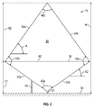
- FIG. 2 is an exemplary embodiment of the antenna 10, where the antenna 10 has an overall height H of about 23.3 centimeters (9.2 inches) and an overall width W of about 21.3 centimeters (8.4 inches).
- the height H is measured from the ground plane 54 to the top most corner 40c of the antenna 10.
- the width W is measured from the leftmost corner 40b to the rightmost corner 40b.
- the antenna 10 may include any size having a height to width ratio of 9.2 to 8.4.
- the antenna 10 may have a height of about 46.7 centimeters (18.4 inches) and a width of about 42.6 centimeters (16.8 inches), but still includes a height to width ratio of 9.2 to 8.4.
- the matching circuit 56 includes a 150 ohm resistor. Furthermore, the matching circuit 56 is positioned about 1.27 centimeters (half an inch) away from the feed 52.
- the height H of the antenna 10 is divided into two sections, a first height H1 and a second height H2.
- the first height H1 is measured from the ground plane 54 to the horizontal line 60
- the second height H2 is measured from the horizontal line 60 to the top most corner 40c of the antenna 10.
- the ratio of the first height H1 and the second height H2 is 3.2 to 6.
- an angle A may be measured between the horizontal line 60 and one of the upper sides 34a, 34b. In the embodiment as shown in FIG. 2 , the angle A is about 55°.
- a second angle A2 may also be measured between one of the bottom sides 32a, 32b and the ground plane 54. In the embodiment as shown in FIG. 2 , the second angle A2 is about 35.7°.
- the antenna 10 has a voltage standing wave ratio (VSWR) of less than 3:1 at frequencies ranging from about 20 to about 500 Megahertz (MHz).
- the antenna 10 may also include an electrical height of about 0.015 wavelengths at its lowest operating frequency.
- the antenna 10 having the dimensions as shown in FIG. 2 i.e., the height H is about 23.3 cm (9.2 inches) and the width W is about 21.3 cm (8.4 inches)) provides about 184.6% impedance bandwidth.
- the disclosed antenna 10 is a broadband blade monopole antenna that includes a relatively simple design, and is also inexpensive to manufacture. Indeed, the antenna 10 may be manufactured using relatively low-cost manufacturing processes such as, but not limited to, metal stamping. Moreover, the antenna 10 does not typically require machining or any other labor-intensive manufacturing processes. Finally, it should be appreciated that the overall kite-shaped outer profile as seen in the figures may enhance efficiency and the overall aerodynamic shape of the antenna 10.
Landscapes
- Physics & Mathematics (AREA)
- Engineering & Computer Science (AREA)
- Remote Sensing (AREA)
- Fluid Mechanics (AREA)
- Astronomy & Astrophysics (AREA)
- Aviation & Aerospace Engineering (AREA)
- General Physics & Mathematics (AREA)
- Details Of Aerials (AREA)
Abstract
Description
- The disclosed system relates to an antenna and, more particularly, to a broadband blade monopole antenna that is substantially flat and defines a kite-shaped outer perimeter.
- Antennas are generally used to transform electrical power into a radiated wave, and vice-versa. There are numerous types of antennas that are currently available that may be selected based on the specific application. For example, a broadband antenna may be distinguished by its relatively wide bandwidth, thereby making the broadband antenna highly desirable for certain types of applications. In general, a broadband antenna provides at least about 100% impedance bandwidth, and operates over a frequency greater than about twenty-five percent of its center operating frequency.
- Although broadband antennas have numerous advantages, it may be challenging to produce a low-cost broadband antenna that has specific performance characteristics required for a particular application. Some examples of antenna performance characteristics include, but are not limited to, impedance bandwidth, electrical size, voltage standing wave ratio (VSWR) at a specific frequency, gain patterns, aerodynamic qualities, and packaging constraints. In particular, it may be especially challenging to produce a broadband antenna that has a relatively high impedance bandwidth that is electrically small in size, and that is also relatively inexpensive to manufacture. Thus, there exists a continuing need in the art for a cost-effective broadband antenna that is relatively simple and inexpensive to produce.
- The disclosed antenna is a broadband blade monopole antenna that includes a relatively simple design, and is also inexpensive to manufacture. Indeed, the antenna may be manufactured using relatively low-cost manufacturing processes such as, but not limited to, metal stamping. Moreover, the antenna does not typically require machining or any other labor-intensive manufacturing processes. Finally, it should be appreciated that the overall kite-shaped outer profile as seen in the figures may enhance efficiency and the overall aerodynamic shape of the antenna.
- In one aspect, a broadband blade monopole antenna is disclosed. The broadband blade monopole antenna includes a body portion that is substantially flat to define a two-dimensional plane that the body portion extends along. The body portion defines an outer perimeter having four sides. The four sides are grouped into two pairs of equal-length sides positioned directly adjacent to each other. The broadband blade monopole antenna provides at least about 100% impedance bandwidth.
- In another aspect, a broadband blade monopole antenna is disclosed. The broadband blade monopole antenna includes a body portion that is a solid piece and has a height to width ratio of 9.2 to 8.4. The body portion is substantially flat to define a two-dimensional plane that the body portion extends along. The body portion defines a kite-shaped outer perimeter having four sides. The four sides are grouped into two pairs of equal-length sides positioned directly adjacent to each other. The broadband blade monopole antenna provides at least about 100% impedance bandwidth.
- Other objects and advantages of the disclosed method and system will be apparent from the following description, the accompanying drawings and the appended claims.
-
-
FIG. 1 is a front view of the disclosed antenna connected to a feed point and a ground plane; and -
FIG. 2 is an illustration of one exemplary embodiment of the antenna shown inFIG. 1 , where the antenna includes a height to width ratio of 9.2 to 8.4. -
FIG. 1 is an illustration of the disclosedantenna 10. In the embodiments as disclosed, theantenna 10 may be a broadband blade monopole antenna. That is, theantenna 10 provides at least about 100% impedance bandwidth, and operates over a frequency greater than about twenty-five percent of its center operating frequency. In one exemplary embodiment, which is described in greater detail below and illustrated inFIG. 2 , theantenna 10 may provide about 184.6% impedance bandwidth. However, it is to be understood that the disclosedantenna 10 is not limited to the specific embodiment as shown inFIG. 2 . Theantenna 10 may be used in very high frequency (VHF) as well as ultra high frequency (UHF) applications. - Referring back to
FIG. 1 , theantenna 10 may define abody portion 20. Thebody portion 20 of theantenna 10 may be substantially flat, thereby defining a relatively flat two-dimensional plane that thebody portion 20 extends along. Specifically, in one embodiment, theantenna 10 may be substantially flat so that there is no more than 1.27 centimeters (0.5 inches) of distortion along the two-dimensional plane that thebody portion 20 defines. In one embodiment, thebody portion 20 of theantenna 10 may be constructed of a metal material such as, for example, aluminum or any other conductive material. In another embodiment, theantenna 10 may be constructed of a printed circuit material. It is to be appreciated that theantenna 10 may be created using a relatively simple, low-cost manufacturing process, thereby lowering the overall cost of theantenna 10. For example, in one approach, theantenna 10 may be a stamped metal part that requires minimal or no machining, or any other labor-intensive manufacturing processes. - In the non-limiting embodiment as shown in
FIG. 1 , thebody portion 20 of theantenna 10 is a solid piece. That is, there are no holes, slots, cavities, indentations, or other types of irregularities along anouter surface 24 of theantenna 10. It is to be appreciated that features such as holes, slots, or other irregularities along theouter surface 24 of thebody portion 20 may add cost and complexity to theantenna 10. However, it should also be appreciated that theantenna 10 is not limited to just a solid body. Indeed, in another embodiment, theantenna 10 may include irregularities such as holes, or slots. However, it should be appreciated that such features may increase the overall cost to manufacture theantenna 10. - In the embodiment as shown, the
antenna 10 defines anouter perimeter 30. Theouter perimeter 30 of theantenna 10 defines four sides, which areside 32a,side 32b,side 34a, andside 34b. As seen inFIG. 1 , thesides lower portion 36 of theantenna 10. Thesides sides sides upper portion 38 of theantenna 10. Thesides sides - As seen in
FIG. 1 , the length L1 ofsides sides antenna 10. Furthermore, theouter perimeter 30 of theantenna 10 defines a generally kite-shaped outer profile. Specifically, the kite-shapedouter perimeter 30 of theantenna 10 defines a quadrilateral including foursides corners sides outer perimeter 30 of theantenna 10 may be grouped into two pairs of equal-length sides that are positioned directly adjacent to each other. Specifically, thesides antenna 10, which are equal to one another in length, are positioned directly adjacent to one another. Furthermore, thesides antenna 10, which are also equal to one another in length, are also positioned directly adjacent to one another. Also, thebody portion 20 is symmetrical about its longitudinal axis A-A. - In one non-limiting embodiment, the
corner 40a, which is located at alowermost portion 50 of theantenna 10, may be electrically connected to afeed 52. Thefeed 52 may be connected to aground plane 54. Theground plane 54 may be a conductive surface such as, for example, the skin of an aircraft. It is to be appreciated that the term "lowermost portion" refers to a portion of theantenna 10 which is closest to theground plane 54, regardless of the actual orientation of theantenna 10. It is to be appreciated that the overall kite-shapedouter perimeter 30 of theantenna 10 defines an aerodynamic profile. The aerodynamic profile of theantenna 10 may result in reduced drag when compared to other profiles that are currently used for antennas, which is especially beneficial in aircraft applications. Furthermore, theantenna 10 may be omnidirectional antenna with respect to azimuth. That is, theantenna 10 may include a generally uniform gain as the antenna rotates in azimuth. Theantenna 10 may cover multiple contiguous frequency bands, and is relatively electrically small in size. For example, in the embodiment as shown inFIG. 2 , theantenna 10 may include an electrical height of about 0.015 wavelengths at its lowest operating frequency. - Turning back to
FIG. 1 , in one non-limiting embodiment, theantenna 10 may be electrically connected to amatching circuit 56. Specifically, the matchingcircuit 56 may be electrically connected to theside 32a of theantenna 10 as well as theground plane 54. However, in another embodiment, the matchingcircuit 56 may be electrically connected to one of theother sides antenna 10 instead. The matchingcircuit 56 may include at least one passive linear element. Some examples of passive linear elements include resistors, capacitors, and inductors. It should also be appreciated that the matchingcircuit 56 may include any combination of one or more passive linear elements. In one non-limiting embodiment which is described below and is shown inFIG. 2 , the matchingcircuit 56 may include a 150 ohm resistor. - It should be appreciated that the matching
circuit 56 is optional, and may or may not be included with theantenna 10. However, the matchingcircuit 56 may widen the bandwidth of theantenna 10. It should also be appreciated that the position of the matchingcircuit 56 relative to thefeed 52 may also be adjusted based on the specific dimensions and requirements of theantenna 10. Specifically, the matchingcircuit 56 may be positioned at adistance 58 from thefeed 52. It is to be appreciated that the matchingcircuit 56 may be moved towards thefeed 52 or away from thefeed 52 depending on the requirements of theantenna 10. In the exemplary embodiment as shown inFIG. 2 , the matchingcircuit 56 is positioned about about 1.27 centimeters (half an inch) from thefeed 52. - The
sides lower portion 36 of theantenna 10 define a bevel with respect to theground plane 54. That is, thesides lower portion 36 of theantenna 10 are not oriented at a right angle that is perpendicular with respect to theground plane 54. Instead, thesides ground plane 54. Thesides upper portion 38 of theantenna 10 may be slanted or angled as well. -
FIG. 2 is an exemplary embodiment of theantenna 10, where theantenna 10 has an overall height H of about 23.3 centimeters (9.2 inches) and an overall width W of about 21.3 centimeters (8.4 inches). The height H is measured from theground plane 54 to the topmost corner 40c of theantenna 10. The width W is measured from theleftmost corner 40b to therightmost corner 40b. It is to be understood that in one embodiment, theantenna 10 may include any size having a height to width ratio of 9.2 to 8.4. For example, in another embodiment, theantenna 10 may have a height of about 46.7 centimeters (18.4 inches) and a width of about 42.6 centimeters (16.8 inches), but still includes a height to width ratio of 9.2 to 8.4. In the non-limiting embodiment shown inFIG. 2 , the matchingcircuit 56 includes a 150 ohm resistor. Furthermore, the matchingcircuit 56 is positioned about 1.27 centimeters (half an inch) away from thefeed 52. - As seen in
FIG. 2 , if a substantiallyhorizontal line 60 is drawn through thecorners antenna 10, then the height H of theantenna 10 is divided into two sections, a first height H1 and a second height H2. The first height H1 is measured from theground plane 54 to thehorizontal line 60, and the second height H2 is measured from thehorizontal line 60 to the topmost corner 40c of theantenna 10. The ratio of the first height H1 and the second height H2 is 3.2 to 6. Furthermore, an angle A may be measured between thehorizontal line 60 and one of theupper sides FIG. 2 , the angle A is about 55°. A second angle A2 may also be measured between one of thebottom sides ground plane 54. In the embodiment as shown inFIG. 2 , the second angle A2 is about 35.7°. - In the embodiment as shown in
FIG. 2 , theantenna 10 has a voltage standing wave ratio (VSWR) of less than 3:1 at frequencies ranging from about 20 to about 500 Megahertz (MHz). Theantenna 10 may also include an electrical height of about 0.015 wavelengths at its lowest operating frequency. Moreover, theantenna 10 having the dimensions as shown inFIG. 2 (i.e., the height H is about 23.3 cm (9.2 inches) and the width W is about 21.3 cm (8.4 inches)) provides about 184.6% impedance bandwidth. - Referring generally to the figures, the disclosed
antenna 10 is a broadband blade monopole antenna that includes a relatively simple design, and is also inexpensive to manufacture. Indeed, theantenna 10 may be manufactured using relatively low-cost manufacturing processes such as, but not limited to, metal stamping. Moreover, theantenna 10 does not typically require machining or any other labor-intensive manufacturing processes. Finally, it should be appreciated that the overall kite-shaped outer profile as seen in the figures may enhance efficiency and the overall aerodynamic shape of theantenna 10. - Further, the disclosure comprises embodiments according to the following clauses:
- Clause 1: A broadband blade monopole antenna, comprising: a body portion that is substantially flat to define a two-dimensional plane that the body portion extends along, the body portion defining an outer perimeter having four sides, wherein the four sides are grouped into two pairs of equal-length sides, the two pairs of equal-length sides are positioned directly adjacent to each other, and wherein the broadband blade monopole antenna provides at least 100% impedance bandwidth.
- Clause 2: The broadband blade monopole antenna of clause 1, wherein the body portion defines four corners and the outer perimeter of the body portion is kite-shaped.
- Clause 3: The broadband blade monopole antenna of clause 2, wherein a corner located at a lowermost portion of the antenna is electrically connected to a feed point.
- Clause 3A: The broadband plane monopole antenna of clause 3, wherein the corner at the lowermost portion of the antenna is defined by a first pair of equal-length sides, and wherein each side of the first pair of equal-length sides has a length that is less than a length of each side of the second pair of equal-length sides.
- Clause 4: The broadband blade monopole antenna of clause 3, wherein the feed point is connected to a ground plane.
- Clause 5: The broadband blade monopole antenna of clause 1, wherein the body portion is symmetrical about a longitudinal axis of the antenna.
- Clause 5A: The broadband blade monopole antenna of clause 5, wherein the longitudinal axis is substantialle perpendicular to the ground plane.
- Clause 6: The broadband blade monopole antenna of clause 1, wherein the body portion of the antenna defines a height to width ratio of substantially 9.2 to 8.4.
- Clause 7: The broadband blade monopole antenna of clause 6, wherein the antenna includes an electrical height of about 0.015 wavelengths at a lowest operating frequency.
- Clause 8: The broadband blade monopole antenna of clause 6, wherein the antenna has a voltage standing wave ratio (VSWR) of less than 3:1 at frequencies ranging from about 20 to about 500 Megahertz (MHz) and about 184.6% impedance bandwidth.
- Clause 9: The broadband blade monopole antenna of clause 6, comprising a matching circuit that is electrically connected to one of the four sides of the antenna, wherein the matching circuit includes a 150 ohm resistor.
- Clause 10: The broadband blade monopole antenna of clause 1, comprising a matching circuit that is electrically connected to one of the four sides of the antenna.
- Clause 11: The broadband blade monopole antenna of
clause 10, wherein the matching circuit is electrically connected to a ground plane. - Clause 12: The broadband blade monopole antenna of
clause 10, wherein the matching circuit includes at least one passive linear element. - Clause 13: The broadband blade monopole antenna of clause 1, wherein the body portion of the antenna is a solid piece.
- Clause 14: A broadband blade monopole antenna, comprising: a body portion that is a solid piece and has a height to width ratio of 9.2 to 8.4, the body portion being substantially flat to define a two-dimensional plane that the body portion extends along, the body portion defining a kite-shaped outer perimeter having four sides, wherein the four sides are grouped into two pairs of equal-length sides, wherein the two pairs of equal-length sides are positioned directly adjacent to each other, and wherein the broadband blade monopole antenna provides at least 100% impedance bandwidth.
- Clause 15: The broadband blade monopole antenna of clause 14, wherein the body portion defines four corners.
- Clause 16: The broadband blade monopole antenna of clause 15, wherein a corner located at a lowermost portion of the antenna is electrically connected to a feed point.
- Clause 17: The broadband blade monopole antenna of clause 14, wherein the antenna includes an electrical height of about 0.015 wavelengths at a lowest operating frequency.
- Clause 18: The broadband blade monopole antenna of clause 14, wherein the body portion is symmetrical about a longitudinal axis of the antenna.
- Clause 19: The broadband blade monopole antenna of clause 14, wherein the antenna has a voltage standing wave ratio (VSWR) of less than 3:1 at frequencies ranging from about 20 to about 500 Megahertz (MHz) and about 184.6% impedance bandwidth.
- Clause 20: The broadband blade monopole antenna of claim 14, comprising a matching circuit that is electrically connected to one of the four sides of the antenna, wherein the matching circuit includes a 150 ohm resistor.
- While the forms of apparatus and methods herein described constitute preferred aspects of this disclosure, it is to be understood that the disclosure is not limited to these precise forms of apparatus and methods, and that changes may be made therein without departing from the scope of the disclosure.
Claims (13)
- A broadband blade monopole antenna (10), comprising:a body portion (20) that is substantially flat to define a two-dimensional plane that the body portion extends along, the body portion defining an outer perimeter (30) having four sides (32a, 32b, 34a, 34b), wherein the four sides are grouped into two pairs of equal-length sides (L1, L2), the two pairs of equal-length sides are positioned directly adjacent to each other, and wherein the broadband blade monopole antenna provides at least 100% impedance bandwidth.
- The broadband blade monopole antenna of claim 1, wherein the body portion defines four corners (40a, 40b, 40c, 40d) and the outer perimeter of the body portion is kite-shaped.
- The broadband blade monopole antenna of claim 2, wherein a corner (40a, 40b, 40c, 40d) located at a lowermost portion (50) of the antenna is electrically connected to a feed point (52).
- The broadband blade monopole antenna of claim 3, wherein the feed point is connected to a ground plane (54).
- The broadband blade monopole antenna of any one of the preceding claims, wherein the body portion is symmetrical about a longitudinal axis (A-A) of the antenna.
- The broadband blade monopole antenna of any one of the preceding claims, wherein the body portion of the antenna defines a height (H) to width (W) ratio of 9.2 to 8.4.
- The broadband blade monopole antenna of claim 6, wherein the antenna includes an electrical height (H) of about 0.015 wavelengths at a lowest operating frequency.
- The broadband blade monopole antenna of claim 6 or 7, wherein the antenna has a voltage standing wave ratio (VSWR) of less than 3:1 at frequencies ranging from about 20 to about 500 Megahertz (MHz) and about 184.6% impedance bandwidth.
- The broadband blade monopole antenna of any one of the preceding claims, comprising a matching circuit that is electrically connected to one of the four sides of the antenna.
- The broadband blade monopole antenna of claim 9, wherein the matching circuit is electrically connected to a ground plane.
- The broadband blade monopole antenna of claim 9 or 10, wherein the matching circuit includes at least one passive linear element.
- The broadband blade monopole antenna of any one of claims 6-8 and claim 11, wherein the matching circuit includes a 150 ohm resistor.
- The broadband blade monopole antenna of any one of the preceding claims, wherein the body portion of the antenna is a solid piece.
Applications Claiming Priority (1)
| Application Number | Priority Date | Filing Date | Title |
|---|---|---|---|
| US14/845,970 US10056694B2 (en) | 2015-09-04 | 2015-09-04 | Broadband blade antenna defining a kite-shaped outer profile |
Publications (2)
| Publication Number | Publication Date |
|---|---|
| EP3139439A1 true EP3139439A1 (en) | 2017-03-08 |
| EP3139439B1 EP3139439B1 (en) | 2021-05-26 |
Family
ID=56855375
Family Applications (1)
| Application Number | Title | Priority Date | Filing Date |
|---|---|---|---|
| EP16187220.5A Active EP3139439B1 (en) | 2015-09-04 | 2016-09-05 | Broadband blade antenna defining a kite-shaped outer profile |
Country Status (3)
| Country | Link |
|---|---|
| US (1) | US10056694B2 (en) |
| EP (1) | EP3139439B1 (en) |
| RU (1) | RU2711528C2 (en) |
Citations (3)
| Publication number | Priority date | Publication date | Assignee | Title |
|---|---|---|---|---|
| US2568710A (en) * | 1945-11-13 | 1951-09-25 | John T Bolljahn | Wide-band antenna |
| US20030076269A1 (en) * | 2001-10-24 | 2003-04-24 | Nec Corporation | Antenna element |
| US20050110687A1 (en) * | 2003-11-21 | 2005-05-26 | Starkie Timothy J.S. | Ultrawideband antenna |
Family Cites Families (5)
| Publication number | Priority date | Publication date | Assignee | Title |
|---|---|---|---|---|
| AU2003286082A1 (en) * | 2003-02-14 | 2004-09-06 | Huber + Suhner Ag | Wideband monopole antenna |
| US7248223B2 (en) * | 2005-12-05 | 2007-07-24 | Elta Systems Ltd | Fractal monopole antenna |
| AU2007297622A1 (en) * | 2006-09-21 | 2008-03-27 | Noninvasive Medical Technologies, Inc. | Antenna for thoracic radio interrogation |
| US8279125B2 (en) * | 2009-12-21 | 2012-10-02 | Symbol Technologies, Inc. | Compact circular polarized monopole and slot UHF RFID antenna systems and methods |
| US8531344B2 (en) * | 2010-06-28 | 2013-09-10 | Blackberry Limited | Broadband monopole antenna with dual radiating structures |
-
2015
- 2015-09-04 US US14/845,970 patent/US10056694B2/en active Active
-
2016
- 2016-07-26 RU RU2016130693A patent/RU2711528C2/en active
- 2016-09-05 EP EP16187220.5A patent/EP3139439B1/en active Active
Patent Citations (3)
| Publication number | Priority date | Publication date | Assignee | Title |
|---|---|---|---|---|
| US2568710A (en) * | 1945-11-13 | 1951-09-25 | John T Bolljahn | Wide-band antenna |
| US20030076269A1 (en) * | 2001-10-24 | 2003-04-24 | Nec Corporation | Antenna element |
| US20050110687A1 (en) * | 2003-11-21 | 2005-05-26 | Starkie Timothy J.S. | Ultrawideband antenna |
Non-Patent Citations (3)
| Title |
|---|
| AHIRWAR S D ET AL: "Broadband blade monopole antenna covering 100-2000 MHz frequency band", APPLIED ELECTROMAGNETICS CONFERENCE (AEMC), 2009, IEEE, PISCATAWAY, NJ, USA, 14 December 2009 (2009-12-14), pages 1 - 4, XP031648449, ISBN: 978-1-4244-4818-0 * |
| AMMANN M J ET AL: "SMALL PLANAR MONOPOLE COVERS MULTIBAND BRANS", 30TH EUROPEAN MICROWAVE CONFERENCE PROCEEDINGS. PARIS, OCT. 3 - 5, 2000; [PROCEEDINGS OF THE EUROPEAN MICROWAVE CONFERENCE], LONDON : CMP, GB, vol. CONF. 30, 4 October 2000 (2000-10-04), pages 242 - 245, XP001060920, ISBN: 978-0-86213-212-5 * |
| LILIA MANAC'H ET AL: "PERFORMANCE OF A LOZENGE MONOPOLE ANTENNA MADE OF PURE COMPOSITE LAMINATE", PROGRESS IN ELECTROMAGNETICS RESEARCH LETTERS, vol. 35, 1 January 2012 (2012-01-01), pages 115 - 123, XP055126259, DOI: 10.2528/PIERL12083003 * |
Also Published As
| Publication number | Publication date |
|---|---|
| RU2711528C2 (en) | 2020-01-17 |
| US20170069971A1 (en) | 2017-03-09 |
| EP3139439B1 (en) | 2021-05-26 |
| RU2016130693A3 (en) | 2019-11-11 |
| US10056694B2 (en) | 2018-08-21 |
| RU2016130693A (en) | 2018-01-31 |
Similar Documents
| Publication | Publication Date | Title |
|---|---|---|
| US9537220B2 (en) | Antenna assembly and wireless communication device employing same | |
| US9431712B2 (en) | Electrically-small, low-profile, ultra-wideband antenna | |
| TWI652859B (en) | Antenna structure | |
| US20160365647A1 (en) | Shared-aperture antenna and base station | |
| KR101850061B1 (en) | The Wide band Antenna for a Vehicle | |
| US9431711B2 (en) | Broadband multi-strip patch antenna | |
| Ghosh et al. | Miniaturization of slot antennas using wire loading | |
| US9142884B2 (en) | Antenna device | |
| KR101843305B1 (en) | Wideband cavity backed antenna | |
| US8878742B1 (en) | Dipole with an unbalanced microstrip feed | |
| CN109309279B (en) | Antenna structure | |
| CN112490652A (en) | X-band multi-slot loading broadband millimeter wave microstrip antenna | |
| CN203690491U (en) | Ultra-wideband antenna with WLAN dual band-notched characteristic | |
| Hua et al. | Printed UWB heart-shaped monopole antenna with band-notch reconfigurability | |
| CN103715511A (en) | Micro-strip tag antenna | |
| US7567210B2 (en) | Small size ultra-wideband antenna | |
| US20190044233A1 (en) | Antenna | |
| US10056694B2 (en) | Broadband blade antenna defining a kite-shaped outer profile | |
| Chen et al. | Printed broadband monopole antenna for WLAN/WiMAX applications | |
| Teotia et al. | CPW-Fed dodecagram fractal antenna with DGS for multiband applications | |
| US20140333501A1 (en) | Ultrabroadband antenna | |
| CN205646136U (en) | Trapped wave ultra wide band antenna based on n-shaped groove | |
| CN203690501U (en) | Novel triple band-notched ultra-wideband antenna | |
| TWI685146B (en) | High impedance structure and antenna device based on the same | |
| CN105789897A (en) | EBG structure-based three-notch UWB antenna |
Legal Events
| Date | Code | Title | Description |
|---|---|---|---|
| PUAI | Public reference made under article 153(3) epc to a published international application that has entered the european phase |
Free format text: ORIGINAL CODE: 0009012 |
|
| STAA | Information on the status of an ep patent application or granted ep patent |
Free format text: STATUS: REQUEST FOR EXAMINATION WAS MADE |
|
| 17P | Request for examination filed |
Effective date: 20160905 |
|
| AK | Designated contracting states |
Kind code of ref document: A1 Designated state(s): AL AT BE BG CH CY CZ DE DK EE ES FI FR GB GR HR HU IE IS IT LI LT LU LV MC MK MT NL NO PL PT RO RS SE SI SK SM TR |
|
| AX | Request for extension of the european patent |
Extension state: BA ME |
|
| STAA | Information on the status of an ep patent application or granted ep patent |
Free format text: STATUS: EXAMINATION IS IN PROGRESS |
|
| 17Q | First examination report despatched |
Effective date: 20191118 |
|
| GRAP | Despatch of communication of intention to grant a patent |
Free format text: ORIGINAL CODE: EPIDOSNIGR1 |
|
| STAA | Information on the status of an ep patent application or granted ep patent |
Free format text: STATUS: GRANT OF PATENT IS INTENDED |
|
| INTG | Intention to grant announced |
Effective date: 20201216 |
|
| GRAS | Grant fee paid |
Free format text: ORIGINAL CODE: EPIDOSNIGR3 |
|
| GRAA | (expected) grant |
Free format text: ORIGINAL CODE: 0009210 |
|
| STAA | Information on the status of an ep patent application or granted ep patent |
Free format text: STATUS: THE PATENT HAS BEEN GRANTED |
|
| AK | Designated contracting states |
Kind code of ref document: B1 Designated state(s): AL AT BE BG CH CY CZ DE DK EE ES FI FR GB GR HR HU IE IS IT LI LT LU LV MC MK MT NL NO PL PT RO RS SE SI SK SM TR |
|
| REG | Reference to a national code |
Ref country code: GB Ref legal event code: FG4D |
|
| REG | Reference to a national code |
Ref country code: CH Ref legal event code: EP |
|
| REG | Reference to a national code |
Ref country code: AT Ref legal event code: REF Ref document number: 1397156 Country of ref document: AT Kind code of ref document: T Effective date: 20210615 |
|
| REG | Reference to a national code |
Ref country code: DE Ref legal event code: R096 Ref document number: 602016058328 Country of ref document: DE |
|
| REG | Reference to a national code |
Ref country code: IE Ref legal event code: FG4D |
|
| REG | Reference to a national code |
Ref country code: LT Ref legal event code: MG9D |
|
| REG | Reference to a national code |
Ref country code: AT Ref legal event code: MK05 Ref document number: 1397156 Country of ref document: AT Kind code of ref document: T Effective date: 20210526 |
|
| PG25 | Lapsed in a contracting state [announced via postgrant information from national office to epo] |
Ref country code: LT Free format text: LAPSE BECAUSE OF FAILURE TO SUBMIT A TRANSLATION OF THE DESCRIPTION OR TO PAY THE FEE WITHIN THE PRESCRIBED TIME-LIMIT Effective date: 20210526 Ref country code: FI Free format text: LAPSE BECAUSE OF FAILURE TO SUBMIT A TRANSLATION OF THE DESCRIPTION OR TO PAY THE FEE WITHIN THE PRESCRIBED TIME-LIMIT Effective date: 20210526 Ref country code: BG Free format text: LAPSE BECAUSE OF FAILURE TO SUBMIT A TRANSLATION OF THE DESCRIPTION OR TO PAY THE FEE WITHIN THE PRESCRIBED TIME-LIMIT Effective date: 20210826 Ref country code: AT Free format text: LAPSE BECAUSE OF FAILURE TO SUBMIT A TRANSLATION OF THE DESCRIPTION OR TO PAY THE FEE WITHIN THE PRESCRIBED TIME-LIMIT Effective date: 20210526 Ref country code: HR Free format text: LAPSE BECAUSE OF FAILURE TO SUBMIT A TRANSLATION OF THE DESCRIPTION OR TO PAY THE FEE WITHIN THE PRESCRIBED TIME-LIMIT Effective date: 20210526 |
|
| REG | Reference to a national code |
Ref country code: NL Ref legal event code: MP Effective date: 20210526 |
|
| PG25 | Lapsed in a contracting state [announced via postgrant information from national office to epo] |
Ref country code: LV Free format text: LAPSE BECAUSE OF FAILURE TO SUBMIT A TRANSLATION OF THE DESCRIPTION OR TO PAY THE FEE WITHIN THE PRESCRIBED TIME-LIMIT Effective date: 20210526 Ref country code: GR Free format text: LAPSE BECAUSE OF FAILURE TO SUBMIT A TRANSLATION OF THE DESCRIPTION OR TO PAY THE FEE WITHIN THE PRESCRIBED TIME-LIMIT Effective date: 20210827 Ref country code: IS Free format text: LAPSE BECAUSE OF FAILURE TO SUBMIT A TRANSLATION OF THE DESCRIPTION OR TO PAY THE FEE WITHIN THE PRESCRIBED TIME-LIMIT Effective date: 20210926 Ref country code: PL Free format text: LAPSE BECAUSE OF FAILURE TO SUBMIT A TRANSLATION OF THE DESCRIPTION OR TO PAY THE FEE WITHIN THE PRESCRIBED TIME-LIMIT Effective date: 20210526 Ref country code: PT Free format text: LAPSE BECAUSE OF FAILURE TO SUBMIT A TRANSLATION OF THE DESCRIPTION OR TO PAY THE FEE WITHIN THE PRESCRIBED TIME-LIMIT Effective date: 20210927 Ref country code: NO Free format text: LAPSE BECAUSE OF FAILURE TO SUBMIT A TRANSLATION OF THE DESCRIPTION OR TO PAY THE FEE WITHIN THE PRESCRIBED TIME-LIMIT Effective date: 20210826 Ref country code: RS Free format text: LAPSE BECAUSE OF FAILURE TO SUBMIT A TRANSLATION OF THE DESCRIPTION OR TO PAY THE FEE WITHIN THE PRESCRIBED TIME-LIMIT Effective date: 20210526 Ref country code: SE Free format text: LAPSE BECAUSE OF FAILURE TO SUBMIT A TRANSLATION OF THE DESCRIPTION OR TO PAY THE FEE WITHIN THE PRESCRIBED TIME-LIMIT Effective date: 20210526 |
|
| PG25 | Lapsed in a contracting state [announced via postgrant information from national office to epo] |
Ref country code: NL Free format text: LAPSE BECAUSE OF FAILURE TO SUBMIT A TRANSLATION OF THE DESCRIPTION OR TO PAY THE FEE WITHIN THE PRESCRIBED TIME-LIMIT Effective date: 20210526 |
|
| PG25 | Lapsed in a contracting state [announced via postgrant information from national office to epo] |
Ref country code: CZ Free format text: LAPSE BECAUSE OF FAILURE TO SUBMIT A TRANSLATION OF THE DESCRIPTION OR TO PAY THE FEE WITHIN THE PRESCRIBED TIME-LIMIT Effective date: 20210526 Ref country code: DK Free format text: LAPSE BECAUSE OF FAILURE TO SUBMIT A TRANSLATION OF THE DESCRIPTION OR TO PAY THE FEE WITHIN THE PRESCRIBED TIME-LIMIT Effective date: 20210526 Ref country code: EE Free format text: LAPSE BECAUSE OF FAILURE TO SUBMIT A TRANSLATION OF THE DESCRIPTION OR TO PAY THE FEE WITHIN THE PRESCRIBED TIME-LIMIT Effective date: 20210526 Ref country code: SM Free format text: LAPSE BECAUSE OF FAILURE TO SUBMIT A TRANSLATION OF THE DESCRIPTION OR TO PAY THE FEE WITHIN THE PRESCRIBED TIME-LIMIT Effective date: 20210526 Ref country code: SK Free format text: LAPSE BECAUSE OF FAILURE TO SUBMIT A TRANSLATION OF THE DESCRIPTION OR TO PAY THE FEE WITHIN THE PRESCRIBED TIME-LIMIT Effective date: 20210526 Ref country code: RO Free format text: LAPSE BECAUSE OF FAILURE TO SUBMIT A TRANSLATION OF THE DESCRIPTION OR TO PAY THE FEE WITHIN THE PRESCRIBED TIME-LIMIT Effective date: 20210526 Ref country code: ES Free format text: LAPSE BECAUSE OF FAILURE TO SUBMIT A TRANSLATION OF THE DESCRIPTION OR TO PAY THE FEE WITHIN THE PRESCRIBED TIME-LIMIT Effective date: 20210526 |
|
| REG | Reference to a national code |
Ref country code: DE Ref legal event code: R097 Ref document number: 602016058328 Country of ref document: DE |
|
| PLBE | No opposition filed within time limit |
Free format text: ORIGINAL CODE: 0009261 |
|
| STAA | Information on the status of an ep patent application or granted ep patent |
Free format text: STATUS: NO OPPOSITION FILED WITHIN TIME LIMIT |
|
| 26N | No opposition filed |
Effective date: 20220301 |
|
| REG | Reference to a national code |
Ref country code: CH Ref legal event code: PL |
|
| REG | Reference to a national code |
Ref country code: BE Ref legal event code: MM Effective date: 20210930 |
|
| PG25 | Lapsed in a contracting state [announced via postgrant information from national office to epo] |
Ref country code: IS Free format text: LAPSE BECAUSE OF FAILURE TO SUBMIT A TRANSLATION OF THE DESCRIPTION OR TO PAY THE FEE WITHIN THE PRESCRIBED TIME-LIMIT Effective date: 20210926 Ref country code: MC Free format text: LAPSE BECAUSE OF FAILURE TO SUBMIT A TRANSLATION OF THE DESCRIPTION OR TO PAY THE FEE WITHIN THE PRESCRIBED TIME-LIMIT Effective date: 20210526 Ref country code: AL Free format text: LAPSE BECAUSE OF FAILURE TO SUBMIT A TRANSLATION OF THE DESCRIPTION OR TO PAY THE FEE WITHIN THE PRESCRIBED TIME-LIMIT Effective date: 20210526 |
|
| PG25 | Lapsed in a contracting state [announced via postgrant information from national office to epo] |
Ref country code: LU Free format text: LAPSE BECAUSE OF NON-PAYMENT OF DUE FEES Effective date: 20210905 Ref country code: IT Free format text: LAPSE BECAUSE OF FAILURE TO SUBMIT A TRANSLATION OF THE DESCRIPTION OR TO PAY THE FEE WITHIN THE PRESCRIBED TIME-LIMIT Effective date: 20210526 Ref country code: IE Free format text: LAPSE BECAUSE OF NON-PAYMENT OF DUE FEES Effective date: 20210905 Ref country code: BE Free format text: LAPSE BECAUSE OF NON-PAYMENT OF DUE FEES Effective date: 20210930 |
|
| PG25 | Lapsed in a contracting state [announced via postgrant information from national office to epo] |
Ref country code: LI Free format text: LAPSE BECAUSE OF NON-PAYMENT OF DUE FEES Effective date: 20210930 Ref country code: CH Free format text: LAPSE BECAUSE OF NON-PAYMENT OF DUE FEES Effective date: 20210930 |
|
| PG25 | Lapsed in a contracting state [announced via postgrant information from national office to epo] |
Ref country code: HU Free format text: LAPSE BECAUSE OF FAILURE TO SUBMIT A TRANSLATION OF THE DESCRIPTION OR TO PAY THE FEE WITHIN THE PRESCRIBED TIME-LIMIT; INVALID AB INITIO Effective date: 20160905 |
|
| P01 | Opt-out of the competence of the unified patent court (upc) registered |
Effective date: 20230516 |
|
| PG25 | Lapsed in a contracting state [announced via postgrant information from national office to epo] |
Ref country code: CY Free format text: LAPSE BECAUSE OF FAILURE TO SUBMIT A TRANSLATION OF THE DESCRIPTION OR TO PAY THE FEE WITHIN THE PRESCRIBED TIME-LIMIT Effective date: 20210526 |
|
| PG25 | Lapsed in a contracting state [announced via postgrant information from national office to epo] |
Ref country code: MK Free format text: LAPSE BECAUSE OF FAILURE TO SUBMIT A TRANSLATION OF THE DESCRIPTION OR TO PAY THE FEE WITHIN THE PRESCRIBED TIME-LIMIT Effective date: 20210526 |
|
| PG25 | Lapsed in a contracting state [announced via postgrant information from national office to epo] |
Ref country code: TR Free format text: LAPSE BECAUSE OF FAILURE TO SUBMIT A TRANSLATION OF THE DESCRIPTION OR TO PAY THE FEE WITHIN THE PRESCRIBED TIME-LIMIT Effective date: 20210526 |
|
| PG25 | Lapsed in a contracting state [announced via postgrant information from national office to epo] |
Ref country code: MT Free format text: LAPSE BECAUSE OF FAILURE TO SUBMIT A TRANSLATION OF THE DESCRIPTION OR TO PAY THE FEE WITHIN THE PRESCRIBED TIME-LIMIT Effective date: 20210526 |
|
| PGFP | Annual fee paid to national office [announced via postgrant information from national office to epo] |
Ref country code: DE Payment date: 20250929 Year of fee payment: 10 |
|
| PGFP | Annual fee paid to national office [announced via postgrant information from national office to epo] |
Ref country code: GB Payment date: 20250929 Year of fee payment: 10 |
|
| PGFP | Annual fee paid to national office [announced via postgrant information from national office to epo] |
Ref country code: FR Payment date: 20250925 Year of fee payment: 10 |