EP3139311A1 - Shield member for selectively securing an electrical device - Google Patents
Shield member for selectively securing an electrical device Download PDFInfo
- Publication number
- EP3139311A1 EP3139311A1 EP16186246.1A EP16186246A EP3139311A1 EP 3139311 A1 EP3139311 A1 EP 3139311A1 EP 16186246 A EP16186246 A EP 16186246A EP 3139311 A1 EP3139311 A1 EP 3139311A1
- Authority
- EP
- European Patent Office
- Prior art keywords
- electrical device
- electrical
- electrical component
- shield member
- door
- Prior art date
- Legal status (The legal status is an assumption and is not a legal conclusion. Google has not performed a legal analysis and makes no representation as to the accuracy of the status listed.)
- Granted
Links
Images


Classifications
-
- G—PHYSICS
- G06—COMPUTING OR CALCULATING; COUNTING
- G06K—GRAPHICAL DATA READING; PRESENTATION OF DATA; RECORD CARRIERS; HANDLING RECORD CARRIERS
- G06K13/00—Conveying record carriers from one station to another, e.g. from stack to punching mechanism
- G06K13/02—Conveying record carriers from one station to another, e.g. from stack to punching mechanism the record carrier having longitudinal dimension comparable with transverse dimension, e.g. punched card
- G06K13/08—Feeding or discharging cards
-
- H—ELECTRICITY
- H05—ELECTRIC TECHNIQUES NOT OTHERWISE PROVIDED FOR
- H05K—PRINTED CIRCUITS; CASINGS OR CONSTRUCTIONAL DETAILS OF ELECTRIC APPARATUS; MANUFACTURE OF ASSEMBLAGES OF ELECTRICAL COMPONENTS
- H05K5/00—Casings, cabinets or drawers for electric apparatus
- H05K5/02—Details
- H05K5/0208—Interlock mechanisms; Means for avoiding unauthorised use or function, e.g. tamperproof
-
- G—PHYSICS
- G06—COMPUTING OR CALCULATING; COUNTING
- G06F—ELECTRIC DIGITAL DATA PROCESSING
- G06F1/00—Details not covered by groups G06F3/00 - G06F13/00 and G06F21/00
- G06F1/16—Constructional details or arrangements
- G06F1/18—Packaging or power distribution
- G06F1/181—Enclosures
- G06F1/182—Enclosures with special features, e.g. for use in industrial environments; grounding or shielding against radio frequency interference [RFI] or electromagnetical interference [EMI]
-
- H—ELECTRICITY
- H05—ELECTRIC TECHNIQUES NOT OTHERWISE PROVIDED FOR
- H05K—PRINTED CIRCUITS; CASINGS OR CONSTRUCTIONAL DETAILS OF ELECTRIC APPARATUS; MANUFACTURE OF ASSEMBLAGES OF ELECTRICAL COMPONENTS
- H05K5/00—Casings, cabinets or drawers for electric apparatus
- H05K5/02—Details
- H05K5/0217—Mechanical details of casings
- H05K5/0226—Hinges
-
- H—ELECTRICITY
- H05—ELECTRIC TECHNIQUES NOT OTHERWISE PROVIDED FOR
- H05K—PRINTED CIRCUITS; CASINGS OR CONSTRUCTIONAL DETAILS OF ELECTRIC APPARATUS; MANUFACTURE OF ASSEMBLAGES OF ELECTRICAL COMPONENTS
- H05K5/00—Casings, cabinets or drawers for electric apparatus
- H05K5/02—Details
- H05K5/03—Covers
Definitions
- Exemplary embodiments pertain to the art of electrical devices and, more particularly, to a shield member for selectively securing an electrical device.
- Cards contain a storage medium that may be accessed by the electrical component.
- cards are inserted into slots provided in the electrical component.
- the slots guide connectors on the card toward, and into alignment with, card receivers. Once connected with the card receiver, data may be transferred between the storage medium of the card and the electrical component.
- prior art systems employ a lid that covers the card.
- the lid is connected to a sensor. If the lid is opened, the sensor triggers a switch that stops any access activity. While providing some measure of protection, a user may still remove the card prior to activity coming to an end.
- an electrical component including a housing having an electrical device receiving slot, and a cover selectively positionable at the electrical device receiving slot.
- the cover includes an electrical device ejector.
- a shield member is pivotally mounted to the housing. The shield member is selectively positionable across the electrical device ejector.
- a shield member control system is operatively connected to the shield member. The shield member control system is operable to release the shield member once communications between the electrical component and an electrical device in the electrical device receiving slot are idle.
- Also disclosed is a method of removing an electrical device from an electrical component including inserting the electrical device into an electrical device receiving slot of the electrical component, initiating communications between the electrical device and the electrical component, stopping communications between the electrical component and the electrical device, releasing a shield member only after communications between the electrical component and the electrical device have stopped thereby exposing an electrical device ejector, activating the electrical device ejector, and removing the electrical device from the electrical component.
- Electrical component 2 includes a housing 4 having a side portion 6.
- Side portion 6 includes a recess 8 within which is positioned an electrical device receiving slot 10.
- electrical device receiving slot 10 receives an electrical device 14 that interfaces with electrical component 2.
- electrical component 2 includes a door 20 that is pivotally mounted across recess 8.
- Door 20 includes a latch 22 that interfaces with a latching portion 25 arranged within recess 8.
- electrical component 2 includes a door position detector 30 mounted within housing 4.
- door position detector 30 senses whether door 20 is open, such as shown in FIG. 1 , or whether door 20 is in a closed position, as shown in FIG. 2 .
- Door position detector 30 includes a first end 32, a second end 33, and an intermediate portion 34 extending therebetween.
- First end 32 includes a door position sensor 36 that may take the form of a photo detector 38, and second end 33 defines a latch engagement member 41.
- first end 32 includes a door position sensor 36 that may take the form of a photo detector 38, and second end 33 defines a latch engagement member 41.
- second end 33 defines a latch engagement member 41.
- Intermediate portion 34 defines a pivot section 44 of door position detector 30.
- door 20 is closed and latch 22 engages with latching portion 25.
- closing door 20 may result in latch 22 engaging with latching portion 25. That is, door 20 may act upon a torsion spring (not shown) operatively associated with latch 22 to facilitate engagement with latching portion 25.
- closing door 20 may also initiate communications between electrical device 14 and electrical component 2.
- Latch 22 also acts upon door position sensor 36, as seen in FIG. 2 . Opening door 20, as shown on FIG. 3 , disengages latch 22 from door position detector 30. First end 32 pivots about pivot section 44 shifting/rotating door position sensor 36. Photo detector 38 is exposed to light passing through a photo pathway 48 indicating that door 20 is open. As will be detailed more fully below, once door 20 is open, communications between electrical device 14 and electrical component 2 are terminated.
- electrical component 2 includes a shield member 60 that is selectively pivotally mounted relative to housing 4 between a first position, as shown in FIG. 1 , and a second position, such as shown in FIG. 4 .
- first position electrical device 14 is retained within electrical device receiving slot 10 and removal is prevented.
- second position electrical device 14 may be removed from electrical device receiving slot 10.
- Shield member 60 includes a latch element 64 that may be retained by a solenoid 68 as will be detailed more fully below.
- electrical component 2 includes a shield member control system 80 operatively connected to solenoid 68.
- shield member control system 80 may take on a variety of forms including electronic components such as relays and/or integrated circuits, as well as other forms of electrical components.
- Shield member control system 80 is also operatively connected to door position sensor 36 and circuit components, indicated generally at 84, that control communications between electrical device 14 and electrical component 2. For example, shield member control system 80 may initiate communications once electrical device 14 is detected in electrical device receiving slot 10, and door 20 is sensed as being in a closed position.
- shield member control system 80 Upon receiving a signal that door 20 has opened through door position sensor 36, shield member control system 80 signals circuit components 84 to cease communications between electrical device 14 and electrical component 2. Once communications have terminated between electrical device 14 and electrical component 2, shield member control system 80 actuates solenoid 68 to release latch element 64 releasing shield member 60 allowing electrical device 14 to be removed.
- electrical device 14 includes an electrical device case 90, such as shown in FIG. 5 .
- Electrical device case 90 includes a cover 92 having an electrical device ejector 94 that is selectively covered by shield member 60. Once shield member 60 is opened, electrical device ejector 94 may be manipulated, as shown in FIG. 6 , to eject electrical device 14 from electrical device receiving slot 10. In this manner, electrical device 14, which may take the form of a memory card 98 having a storage medium 100, may be safely removed from electrical component 2.
- exemplary embodiments describe a system that ensures that communications between an electrical device, such as a memory card, and an electrical component, such as a card reader, a computer, and the like are terminated prior to providing access to remove the electrical device. Further, by locking a shield member with a solenoid in a de-energized state, wear and tear of the solenoid can be reduced and an overall operational life of the system extended. Further, by providing a case with an ejector receptive of an electrical device, unit costs may be reduced. That is, a user may simply purchase an electrical device that may interface with the case without the need to purchase multiple cases.
Landscapes
- Engineering & Computer Science (AREA)
- Theoretical Computer Science (AREA)
- Physics & Mathematics (AREA)
- Microelectronics & Electronic Packaging (AREA)
- General Physics & Mathematics (AREA)
- Computer Hardware Design (AREA)
- Power Engineering (AREA)
- Human Computer Interaction (AREA)
- General Engineering & Computer Science (AREA)
- Electromagnetism (AREA)
- Computer Security & Cryptography (AREA)
- Shielding Devices Or Components To Electric Or Magnetic Fields (AREA)
- Casings For Electric Apparatus (AREA)
Abstract
Description
- Exemplary embodiments pertain to the art of electrical devices and, more particularly, to a shield member for selectively securing an electrical device.
- Electrical devices, including memory cards, data cards, and the like often times interface with an electrical component. Cards contain a storage medium that may be accessed by the electrical component. In many cases, cards are inserted into slots provided in the electrical component. The slots guide connectors on the card toward, and into alignment with, card receivers. Once connected with the card receiver, data may be transferred between the storage medium of the card and the electrical component.
- If the card is removed while being accessed by the electrical component, data may be corrupted, or the storage medium could be damaged. Therefore, it is advantageous to remove the card during periods of inactivity. In order to provide some level of protection, prior art systems employ a lid that covers the card. The lid is connected to a sensor. If the lid is opened, the sensor triggers a switch that stops any access activity. While providing some measure of protection, a user may still remove the card prior to activity coming to an end.
- Disclosed is an electrical component including a housing having an electrical device receiving slot, and a cover selectively positionable at the electrical device receiving slot. The cover includes an electrical device ejector. A shield member is pivotally mounted to the housing. The shield member is selectively positionable across the electrical device ejector. A shield member control system is operatively connected to the shield member. The shield member control system is operable to release the shield member once communications between the electrical component and an electrical device in the electrical device receiving slot are idle.
- Also disclosed is a method of removing an electrical device from an electrical component including inserting the electrical device into an electrical device receiving slot of the electrical component, initiating communications between the electrical device and the electrical component, stopping communications between the electrical component and the electrical device, releasing a shield member only after communications between the electrical component and the electrical device have stopped thereby exposing an electrical device ejector, activating the electrical device ejector, and removing the electrical device from the electrical component.
- The following descriptions should not be considered limiting in any way. With reference to the accompanying drawings, like elements are numbered alike:
-
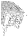
FIG. 1 is partial perspective view of an electrical component, in accordance with an exemplary embodiment, having an electrical device mounted in an electrical device slot; -
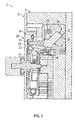
FIG. 2 depicts a partial cross-sectional side view of the electrical component ofFIG. 1 showing a door engaging with a door position detector in a first position, in accordance with an aspect of an exemplary embodiment; -
FIG. 3 depicts a partial cross-sectional side view of the electrical component ofFIG. 1 showing a door engaging with a door position detector in a second position, in accordance with an aspect of an exemplary embodiment; -
FIG. 4 is a partial perspective view of the electrical component ofFIG. 1 showing a shield member exposing an electrical device ejector, in accordance with an aspect of an exemplary embodiment; -
FIG. 5 depicts an electrical device in an electrical device casing, in accordance with an exemplary embodiment; and -
FIG. 6 depicts the electrical component ofFIG. 1 with the shield member in an open position and an electrical device ejector in an activated position, in accordance with an aspect of an exemplary embodiment. - A detailed description of one or more embodiments of the disclosed apparatus and method are presented herein by way of exemplification and not limitation with reference to the Figures.
- An electrical component, in accordance with an exemplary embodiment, is illustrated generally at 2, in
FIG. 1 .Electrical component 2 includes ahousing 4 having aside portion 6.Side portion 6 includes arecess 8 within which is positioned an electricaldevice receiving slot 10. As will be detailed more fully below, electricaldevice receiving slot 10 receives anelectrical device 14 that interfaces withelectrical component 2. In accordance with an aspect of an exemplary embodiment,electrical component 2 includes adoor 20 that is pivotally mounted acrossrecess 8.Door 20 includes alatch 22 that interfaces with alatching portion 25 arranged withinrecess 8. - In accordance with an aspect of an exemplary embodiment illustrated in
FIGs. 2-3 ,electrical component 2 includes adoor position detector 30 mounted withinhousing 4. As will be detailed more fully below,door position detector 30 senses whetherdoor 20 is open, such as shown inFIG. 1 , or whetherdoor 20 is in a closed position, as shown inFIG. 2 .Door position detector 30 includes afirst end 32, asecond end 33, and an intermediate portion 34 extending therebetween.First end 32 includes adoor position sensor 36 that may take the form of aphoto detector 38, andsecond end 33 defines alatch engagement member 41. Of course, it should be understood, that other types of sensors may be employed. - Intermediate portion 34 defines a
pivot section 44 ofdoor position detector 30. In operation,door 20 is closed and latch 22 engages withlatching portion 25. In accordance with an aspect of an exemplary embodiment, closingdoor 20 may result inlatch 22 engaging withlatching portion 25. That is,door 20 may act upon a torsion spring (not shown) operatively associated withlatch 22 to facilitate engagement withlatching portion 25. In accordance with another aspect of an exemplary embodiment, closingdoor 20 may also initiate communications betweenelectrical device 14 andelectrical component 2. Latch 22 also acts upondoor position sensor 36, as seen inFIG. 2 .Opening door 20, as shown onFIG. 3 , disengages latch 22 fromdoor position detector 30.First end 32 pivots aboutpivot section 44 shifting/rotatingdoor position sensor 36.Photo detector 38 is exposed to light passing through aphoto pathway 48 indicating thatdoor 20 is open. As will be detailed more fully below, oncedoor 20 is open, communications betweenelectrical device 14 andelectrical component 2 are terminated. - In further accordance with an aspect of an exemplary embodiment,
electrical component 2 includes ashield member 60 that is selectively pivotally mounted relative tohousing 4 between a first position, as shown inFIG. 1 , and a second position, such as shown inFIG. 4 . In the first position,electrical device 14 is retained within electricaldevice receiving slot 10 and removal is prevented. In the second position,electrical device 14 may be removed from electricaldevice receiving slot 10.Shield member 60 includes alatch element 64 that may be retained by asolenoid 68 as will be detailed more fully below. - In still further accordance with an aspect of an exemplary embodiment,
electrical component 2 includes a shieldmember control system 80 operatively connected tosolenoid 68. At this point it should be understood that shieldmember control system 80 may take on a variety of forms including electronic components such as relays and/or integrated circuits, as well as other forms of electrical components. Shieldmember control system 80 is also operatively connected todoor position sensor 36 and circuit components, indicated generally at 84, that control communications betweenelectrical device 14 andelectrical component 2. For example, shieldmember control system 80 may initiate communications onceelectrical device 14 is detected in electricaldevice receiving slot 10, anddoor 20 is sensed as being in a closed position. Upon receiving a signal thatdoor 20 has opened throughdoor position sensor 36, shieldmember control system 80signals circuit components 84 to cease communications betweenelectrical device 14 andelectrical component 2. Once communications have terminated betweenelectrical device 14 andelectrical component 2, shieldmember control system 80 actuatessolenoid 68 to releaselatch element 64 releasingshield member 60 allowingelectrical device 14 to be removed. - In accordance with an aspect of an exemplary embodiment,
electrical device 14 includes anelectrical device case 90, such as shown inFIG. 5 .Electrical device case 90 includes acover 92 having anelectrical device ejector 94 that is selectively covered byshield member 60. Onceshield member 60 is opened,electrical device ejector 94 may be manipulated, as shown inFIG. 6 , to ejectelectrical device 14 from electricaldevice receiving slot 10. In this manner,electrical device 14, which may take the form of amemory card 98 having astorage medium 100, may be safely removed fromelectrical component 2. - At this point it should be understood that exemplary embodiments describe a system that ensures that communications between an electrical device, such as a memory card, and an electrical component, such as a card reader, a computer, and the like are terminated prior to providing access to remove the electrical device. Further, by locking a shield member with a solenoid in a de-energized state, wear and tear of the solenoid can be reduced and an overall operational life of the system extended. Further, by providing a case with an ejector receptive of an electrical device, unit costs may be reduced. That is, a user may simply purchase an electrical device that may interface with the case without the need to purchase multiple cases.
- The terminology used herein is for the purpose of describing particular embodiments only and is not intended to be limiting of the present disclosure. As used herein, the singular forms "a", "an" and "the" are intended to include the plural forms as well, unless the context clearly indicates otherwise. It will be further understood that the terms "comprises" and/or "comprising," when used in this specification, specify the presence of stated features, integers, steps, operations, elements, and/or components, but do not preclude the presence or addition of one or more other features, integers, steps, operations, element components, and/or groups thereof.
- While the present disclosure has been described with reference to an exemplary embodiment or embodiments, it will be understood by those skilled in the art that various changes may be made and equivalents may be substituted for elements thereof without departing from the scope of the present disclosure. In addition, many modifications may be made to adapt a particular situation or material to the teachings of the present disclosure without departing from the essential scope thereof. Therefore, it is intended that the present disclosure not be limited to the particular embodiment disclosed as the best mode contemplated for carrying out this present disclosure, but that the present disclosure will include all embodiments falling within the scope of the claims.
Claims (15)
- An electrical component (2) comprising:a housing (4) having an electrical device receiving slot (10);a cover (92) selectively positionable at the electrical device receiving slot, the cover including an electrical device ejector (94);a shield member (60) pivotally mounted to the housing (4), the shield member (60) being selectively positionable across the electrical device ejector (94); anda shield member control system operatively connected to the shield member (60), the shield member control system being operable to release the shield member (60) once communications between the electrical component (2) and an electrical device (14) in the electrical device receiving slot (10) are idle.
- The electrical component according to claim 1, further comprising: a door (20) pivotally mounted to the housing (4), the door (20) being selectively positionable across the electrical device receiving slot (10).
- The electrical component according to claim 2, further comprising: a door position detector (30) configured and disposed to detect a position of the door (20).
- The electrical component according to claim 3, further comprising: a latch (22) mounted to the door (20), the latch (22) being configured to engage with the housing (4) to retain the door (20) across the electrical device receiving slot (10).
- The electrical component according to claim 4, wherein the door position detector (30) includes a first end (32), a second end (33), and an intermediate portion (34) defining a pivot section (44), the second end (33) defining a latch engagement member (41 ).
- The electrical component according to claim 5, wherein the first end (32) of the door position detector (30) includes a door position sensor (36).
- The electrical component according to claim 6, wherein the door position sensor (36) comprises a photo detector.
- The electrical component according to claim 1, further comprising: a solenoid (68) mounted to the housing (4) at the shield member (60).
- The electrical component according to claim 8, wherein the shield member (60) includes a latch element (64) selectively connected to the solenoid (68).
- The electrical component according to claim 8, wherein the solenoid (68) is selectively disengageable from the latch element (64) upon being energized.
- The electrical component according to claim 1, wherein the cover (92) defines an electrical device case (90).
- The electrical component according to claim 11, further comprising: an electrical device (14) including a storage medium (100) arranged in the electrical device case (90).
- The electrical component according to claim 12, wherein the electrical device (14) comprises a memory card (98).
- A method of removing an electrical device (14) from an electrical component (2) comprising:inserting the electrical device (14) into an electrical device receiving slot (10) of the electrical component (12);initiating communications between the electrical device (14) and the electrical component (2);stopping communications between the electrical component (2) and the electrical device (14);releasing a shield member (60) only after communications between the electrical component (2) and the electrical device (14) have stopped thereby exposing an electrical device ejector (94);activating the electrical device ejector (94); andremoving the electrical device (14) from the electrical component.
- The method of claim 14, further comprising: closing a door (20) covering the electrical device (14) and the electrical device receiving slot (10).
Applications Claiming Priority (1)
| Application Number | Priority Date | Filing Date | Title |
|---|---|---|---|
| US14/840,825 US9635770B2 (en) | 2015-08-31 | 2015-08-31 | Shield member for selectively securing an electrical device |
Publications (2)
| Publication Number | Publication Date |
|---|---|
| EP3139311A1 true EP3139311A1 (en) | 2017-03-08 |
| EP3139311B1 EP3139311B1 (en) | 2019-08-07 |
Family
ID=57209157
Family Applications (1)
| Application Number | Title | Priority Date | Filing Date |
|---|---|---|---|
| EP16186246.1A Active EP3139311B1 (en) | 2015-08-31 | 2016-08-30 | Shield member for selectively securing an electrical device |
Country Status (2)
| Country | Link |
|---|---|
| US (1) | US9635770B2 (en) |
| EP (1) | EP3139311B1 (en) |
Families Citing this family (3)
| Publication number | Priority date | Publication date | Assignee | Title |
|---|---|---|---|---|
| CN109714915A (en) * | 2017-10-25 | 2019-05-03 | 杭州疆域创新医疗科技有限公司 | Opening-closing structure and electronic device with the opening-closing structure |
| JP7521204B2 (en) * | 2020-02-28 | 2024-07-24 | 京セラドキュメントソリューションズ株式会社 | Cover mounting structure |
| US20230333610A1 (en) * | 2022-04-13 | 2023-10-19 | Dell Products L.P. | Secure hardware component retention assembly |
Citations (4)
| Publication number | Priority date | Publication date | Assignee | Title |
|---|---|---|---|---|
| US5663867A (en) * | 1993-06-21 | 1997-09-02 | Kabushiki Kaisha Toshiba | Portable electronic apparatus having a plurality of card storage portions for removably housing a memory card |
| EP1378857A1 (en) * | 2002-07-03 | 2004-01-07 | Yamaichi Electronics Co., Ltd. | Card connector |
| EP1638382A2 (en) * | 2004-09-16 | 2006-03-22 | Hewlett-Packard Development Company, L.P. | System and method of a computer card slot and bezel |
| EP1729245A2 (en) * | 2005-06-02 | 2006-12-06 | LG Electronics Inc. | Card ejecting mechanism and mobile communication terminal having the same |
Family Cites Families (13)
| Publication number | Priority date | Publication date | Assignee | Title |
|---|---|---|---|---|
| JPS62121653U (en) | 1986-01-21 | 1987-08-01 | ||
| US6088221A (en) * | 1998-06-15 | 2000-07-11 | Compaq Computer Corporation | Hot-pluggable disk drive carrier assembly with no loose parts |
| US6288902B1 (en) * | 1999-05-25 | 2001-09-11 | Hewlett-Packard Company | Modular data storage system for reducing mechanical shock and vibrations |
| JP3555520B2 (en) | 1999-09-27 | 2004-08-18 | 日本電気株式会社 | Medium control device and control method for medium control device |
| JP2001103248A (en) | 1999-09-28 | 2001-04-13 | Toshiba Tec Corp | Optical scanning device |
| US6529374B2 (en) * | 2001-02-26 | 2003-03-04 | Teac Corporation | Electronic apparatus |
| US6856508B2 (en) * | 2002-09-23 | 2005-02-15 | Josef Rabinovitz | Modular data storage device assembly |
| US20110090633A1 (en) * | 2002-09-23 | 2011-04-21 | Josef Rabinovitz | Modular sata data storage device assembly |
| US7227744B2 (en) | 2003-04-25 | 2007-06-05 | Teac Corporation | Data recording device and memory cartridge of data recording device |
| JP4165285B2 (en) * | 2003-04-25 | 2008-10-15 | ティアック株式会社 | Data recording device |
| US7656681B2 (en) * | 2006-01-13 | 2010-02-02 | Tracewell Systems, Inc. | Very light enclosure for electronic systems |
| US7733659B2 (en) * | 2006-08-18 | 2010-06-08 | Delphi Technologies, Inc. | Lightweight audio system for automotive applications and method |
| KR100950938B1 (en) | 2009-07-13 | 2010-04-01 | 주식회사 셀픽 | A apparatus equippted with sensor at insertion hole of memory card and a method for controlling the memory card |
-
2015
- 2015-08-31 US US14/840,825 patent/US9635770B2/en active Active
-
2016
- 2016-08-30 EP EP16186246.1A patent/EP3139311B1/en active Active
Patent Citations (4)
| Publication number | Priority date | Publication date | Assignee | Title |
|---|---|---|---|---|
| US5663867A (en) * | 1993-06-21 | 1997-09-02 | Kabushiki Kaisha Toshiba | Portable electronic apparatus having a plurality of card storage portions for removably housing a memory card |
| EP1378857A1 (en) * | 2002-07-03 | 2004-01-07 | Yamaichi Electronics Co., Ltd. | Card connector |
| EP1638382A2 (en) * | 2004-09-16 | 2006-03-22 | Hewlett-Packard Development Company, L.P. | System and method of a computer card slot and bezel |
| EP1729245A2 (en) * | 2005-06-02 | 2006-12-06 | LG Electronics Inc. | Card ejecting mechanism and mobile communication terminal having the same |
Also Published As
| Publication number | Publication date |
|---|---|
| US9635770B2 (en) | 2017-04-25 |
| US20170064849A1 (en) | 2017-03-02 |
| EP3139311B1 (en) | 2019-08-07 |
Similar Documents
| Publication | Publication Date | Title |
|---|---|---|
| CN102754109B (en) | Card reader | |
| EP3139311B1 (en) | Shield member for selectively securing an electrical device | |
| EP1324256B1 (en) | Card connector | |
| US8167135B2 (en) | Apparatus and method for accepting or dispensing bank notes | |
| EP1830302B1 (en) | Card reader | |
| JP5046722B2 (en) | Electronics | |
| JP6449604B2 (en) | Card reader | |
| JP3708920B2 (en) | Portable printer | |
| JP2002216082A (en) | Memory card connector | |
| JP4935020B2 (en) | Non-contact type IC card reader / writer device | |
| JPH09212591A (en) | IC card read / write device | |
| US10506728B2 (en) | Housing with secure opening | |
| KR100950938B1 (en) | A apparatus equippted with sensor at insertion hole of memory card and a method for controlling the memory card | |
| JP2001022898A (en) | Electronics | |
| JPS625731Y2 (en) | ||
| JP2003122449A (en) | Cover structure of portable electronic equipment | |
| JP6459713B2 (en) | Magnetic card reader and user authentication system | |
| JP3339732B2 (en) | Reader / writer | |
| JP2000172913A (en) | Supply body controller | |
| JPH0327608Y2 (en) | ||
| KR20150129368A (en) | A food garbage pick-up device with card insert arrangement | |
| JPS6243414Y2 (en) | ||
| US10083327B2 (en) | Card reader and control method therefor | |
| CN201522855U (en) | File system damage prevention device of SD card video recorder | |
| JPH10125401A (en) | Medium mounting structure and mounting method |
Legal Events
| Date | Code | Title | Description |
|---|---|---|---|
| PUAI | Public reference made under article 153(3) epc to a published international application that has entered the european phase |
Free format text: ORIGINAL CODE: 0009012 |
|
| STAA | Information on the status of an ep patent application or granted ep patent |
Free format text: STATUS: THE APPLICATION HAS BEEN PUBLISHED |
|
| AK | Designated contracting states |
Kind code of ref document: A1 Designated state(s): AL AT BE BG CH CY CZ DE DK EE ES FI FR GB GR HR HU IE IS IT LI LT LU LV MC MK MT NL NO PL PT RO RS SE SI SK SM TR |
|
| AX | Request for extension of the european patent |
Extension state: BA ME |
|
| STAA | Information on the status of an ep patent application or granted ep patent |
Free format text: STATUS: REQUEST FOR EXAMINATION WAS MADE |
|
| 17P | Request for examination filed |
Effective date: 20170830 |
|
| RBV | Designated contracting states (corrected) |
Designated state(s): AL AT BE BG CH CY CZ DE DK EE ES FI FR GB GR HR HU IE IS IT LI LT LU LV MC MK MT NL NO PL PT RO RS SE SI SK SM TR |
|
| GRAP | Despatch of communication of intention to grant a patent |
Free format text: ORIGINAL CODE: EPIDOSNIGR1 |
|
| STAA | Information on the status of an ep patent application or granted ep patent |
Free format text: STATUS: GRANT OF PATENT IS INTENDED |
|
| INTG | Intention to grant announced |
Effective date: 20190221 |
|
| GRAS | Grant fee paid |
Free format text: ORIGINAL CODE: EPIDOSNIGR3 |
|
| GRAA | (expected) grant |
Free format text: ORIGINAL CODE: 0009210 |
|
| STAA | Information on the status of an ep patent application or granted ep patent |
Free format text: STATUS: THE PATENT HAS BEEN GRANTED |
|
| AK | Designated contracting states |
Kind code of ref document: B1 Designated state(s): AL AT BE BG CH CY CZ DE DK EE ES FI FR GB GR HR HU IE IS IT LI LT LU LV MC MK MT NL NO PL PT RO RS SE SI SK SM TR |
|
| REG | Reference to a national code |
Ref country code: GB Ref legal event code: FG4D |
|
| REG | Reference to a national code |
Ref country code: CH Ref legal event code: EP Ref country code: AT Ref legal event code: REF Ref document number: 1164984 Country of ref document: AT Kind code of ref document: T Effective date: 20190815 |
|
| REG | Reference to a national code |
Ref country code: DE Ref legal event code: R096 Ref document number: 602016018001 Country of ref document: DE |
|
| REG | Reference to a national code |
Ref country code: IE Ref legal event code: FG4D |
|
| REG | Reference to a national code |
Ref country code: NL Ref legal event code: MP Effective date: 20190807 |
|
| REG | Reference to a national code |
Ref country code: LT Ref legal event code: MG4D |
|
| PG25 | Lapsed in a contracting state [announced via postgrant information from national office to epo] |
Ref country code: NL Free format text: LAPSE BECAUSE OF FAILURE TO SUBMIT A TRANSLATION OF THE DESCRIPTION OR TO PAY THE FEE WITHIN THE PRESCRIBED TIME-LIMIT Effective date: 20190807 Ref country code: HR Free format text: LAPSE BECAUSE OF FAILURE TO SUBMIT A TRANSLATION OF THE DESCRIPTION OR TO PAY THE FEE WITHIN THE PRESCRIBED TIME-LIMIT Effective date: 20190807 Ref country code: NO Free format text: LAPSE BECAUSE OF FAILURE TO SUBMIT A TRANSLATION OF THE DESCRIPTION OR TO PAY THE FEE WITHIN THE PRESCRIBED TIME-LIMIT Effective date: 20191107 Ref country code: LT Free format text: LAPSE BECAUSE OF FAILURE TO SUBMIT A TRANSLATION OF THE DESCRIPTION OR TO PAY THE FEE WITHIN THE PRESCRIBED TIME-LIMIT Effective date: 20190807 Ref country code: BG Free format text: LAPSE BECAUSE OF FAILURE TO SUBMIT A TRANSLATION OF THE DESCRIPTION OR TO PAY THE FEE WITHIN THE PRESCRIBED TIME-LIMIT Effective date: 20191107 Ref country code: PT Free format text: LAPSE BECAUSE OF FAILURE TO SUBMIT A TRANSLATION OF THE DESCRIPTION OR TO PAY THE FEE WITHIN THE PRESCRIBED TIME-LIMIT Effective date: 20191209 Ref country code: FI Free format text: LAPSE BECAUSE OF FAILURE TO SUBMIT A TRANSLATION OF THE DESCRIPTION OR TO PAY THE FEE WITHIN THE PRESCRIBED TIME-LIMIT Effective date: 20190807 Ref country code: SE Free format text: LAPSE BECAUSE OF FAILURE TO SUBMIT A TRANSLATION OF THE DESCRIPTION OR TO PAY THE FEE WITHIN THE PRESCRIBED TIME-LIMIT Effective date: 20190807 |
|
| REG | Reference to a national code |
Ref country code: AT Ref legal event code: MK05 Ref document number: 1164984 Country of ref document: AT Kind code of ref document: T Effective date: 20190807 |
|
| PG25 | Lapsed in a contracting state [announced via postgrant information from national office to epo] |
Ref country code: GR Free format text: LAPSE BECAUSE OF FAILURE TO SUBMIT A TRANSLATION OF THE DESCRIPTION OR TO PAY THE FEE WITHIN THE PRESCRIBED TIME-LIMIT Effective date: 20191108 Ref country code: LV Free format text: LAPSE BECAUSE OF FAILURE TO SUBMIT A TRANSLATION OF THE DESCRIPTION OR TO PAY THE FEE WITHIN THE PRESCRIBED TIME-LIMIT Effective date: 20190807 Ref country code: RS Free format text: LAPSE BECAUSE OF FAILURE TO SUBMIT A TRANSLATION OF THE DESCRIPTION OR TO PAY THE FEE WITHIN THE PRESCRIBED TIME-LIMIT Effective date: 20190807 Ref country code: ES Free format text: LAPSE BECAUSE OF FAILURE TO SUBMIT A TRANSLATION OF THE DESCRIPTION OR TO PAY THE FEE WITHIN THE PRESCRIBED TIME-LIMIT Effective date: 20190807 Ref country code: IS Free format text: LAPSE BECAUSE OF FAILURE TO SUBMIT A TRANSLATION OF THE DESCRIPTION OR TO PAY THE FEE WITHIN THE PRESCRIBED TIME-LIMIT Effective date: 20191207 Ref country code: AL Free format text: LAPSE BECAUSE OF FAILURE TO SUBMIT A TRANSLATION OF THE DESCRIPTION OR TO PAY THE FEE WITHIN THE PRESCRIBED TIME-LIMIT Effective date: 20190807 |
|
| PG25 | Lapsed in a contracting state [announced via postgrant information from national office to epo] |
Ref country code: TR Free format text: LAPSE BECAUSE OF FAILURE TO SUBMIT A TRANSLATION OF THE DESCRIPTION OR TO PAY THE FEE WITHIN THE PRESCRIBED TIME-LIMIT Effective date: 20190807 |
|
| PG25 | Lapsed in a contracting state [announced via postgrant information from national office to epo] |
Ref country code: EE Free format text: LAPSE BECAUSE OF FAILURE TO SUBMIT A TRANSLATION OF THE DESCRIPTION OR TO PAY THE FEE WITHIN THE PRESCRIBED TIME-LIMIT Effective date: 20190807 Ref country code: AT Free format text: LAPSE BECAUSE OF FAILURE TO SUBMIT A TRANSLATION OF THE DESCRIPTION OR TO PAY THE FEE WITHIN THE PRESCRIBED TIME-LIMIT Effective date: 20190807 Ref country code: IT Free format text: LAPSE BECAUSE OF FAILURE TO SUBMIT A TRANSLATION OF THE DESCRIPTION OR TO PAY THE FEE WITHIN THE PRESCRIBED TIME-LIMIT Effective date: 20190807 Ref country code: DK Free format text: LAPSE BECAUSE OF FAILURE TO SUBMIT A TRANSLATION OF THE DESCRIPTION OR TO PAY THE FEE WITHIN THE PRESCRIBED TIME-LIMIT Effective date: 20190807 Ref country code: RO Free format text: LAPSE BECAUSE OF FAILURE TO SUBMIT A TRANSLATION OF THE DESCRIPTION OR TO PAY THE FEE WITHIN THE PRESCRIBED TIME-LIMIT Effective date: 20190807 Ref country code: PL Free format text: LAPSE BECAUSE OF FAILURE TO SUBMIT A TRANSLATION OF THE DESCRIPTION OR TO PAY THE FEE WITHIN THE PRESCRIBED TIME-LIMIT Effective date: 20190807 |
|
| PG25 | Lapsed in a contracting state [announced via postgrant information from national office to epo] |
Ref country code: LI Free format text: LAPSE BECAUSE OF NON-PAYMENT OF DUE FEES Effective date: 20190831 Ref country code: LU Free format text: LAPSE BECAUSE OF NON-PAYMENT OF DUE FEES Effective date: 20190830 Ref country code: MC Free format text: LAPSE BECAUSE OF FAILURE TO SUBMIT A TRANSLATION OF THE DESCRIPTION OR TO PAY THE FEE WITHIN THE PRESCRIBED TIME-LIMIT Effective date: 20190807 Ref country code: SK Free format text: LAPSE BECAUSE OF FAILURE TO SUBMIT A TRANSLATION OF THE DESCRIPTION OR TO PAY THE FEE WITHIN THE PRESCRIBED TIME-LIMIT Effective date: 20190807 Ref country code: CZ Free format text: LAPSE BECAUSE OF FAILURE TO SUBMIT A TRANSLATION OF THE DESCRIPTION OR TO PAY THE FEE WITHIN THE PRESCRIBED TIME-LIMIT Effective date: 20190807 Ref country code: CH Free format text: LAPSE BECAUSE OF NON-PAYMENT OF DUE FEES Effective date: 20190831 Ref country code: IS Free format text: LAPSE BECAUSE OF FAILURE TO SUBMIT A TRANSLATION OF THE DESCRIPTION OR TO PAY THE FEE WITHIN THE PRESCRIBED TIME-LIMIT Effective date: 20200224 Ref country code: SM Free format text: LAPSE BECAUSE OF FAILURE TO SUBMIT A TRANSLATION OF THE DESCRIPTION OR TO PAY THE FEE WITHIN THE PRESCRIBED TIME-LIMIT Effective date: 20190807 |
|
| REG | Reference to a national code |
Ref country code: BE Ref legal event code: MM Effective date: 20190831 |
|
| REG | Reference to a national code |
Ref country code: DE Ref legal event code: R097 Ref document number: 602016018001 Country of ref document: DE |
|
| PLBE | No opposition filed within time limit |
Free format text: ORIGINAL CODE: 0009261 |
|
| STAA | Information on the status of an ep patent application or granted ep patent |
Free format text: STATUS: NO OPPOSITION FILED WITHIN TIME LIMIT |
|
| PG2D | Information on lapse in contracting state deleted |
Ref country code: IS |
|
| PG25 | Lapsed in a contracting state [announced via postgrant information from national office to epo] |
Ref country code: IE Free format text: LAPSE BECAUSE OF NON-PAYMENT OF DUE FEES Effective date: 20190830 |
|
| 26N | No opposition filed |
Effective date: 20200603 |
|
| PG25 | Lapsed in a contracting state [announced via postgrant information from national office to epo] |
Ref country code: SI Free format text: LAPSE BECAUSE OF FAILURE TO SUBMIT A TRANSLATION OF THE DESCRIPTION OR TO PAY THE FEE WITHIN THE PRESCRIBED TIME-LIMIT Effective date: 20190807 Ref country code: BE Free format text: LAPSE BECAUSE OF NON-PAYMENT OF DUE FEES Effective date: 20190831 |
|
| PG25 | Lapsed in a contracting state [announced via postgrant information from national office to epo] |
Ref country code: CY Free format text: LAPSE BECAUSE OF FAILURE TO SUBMIT A TRANSLATION OF THE DESCRIPTION OR TO PAY THE FEE WITHIN THE PRESCRIBED TIME-LIMIT Effective date: 20190807 |
|
| PG25 | Lapsed in a contracting state [announced via postgrant information from national office to epo] |
Ref country code: HU Free format text: LAPSE BECAUSE OF FAILURE TO SUBMIT A TRANSLATION OF THE DESCRIPTION OR TO PAY THE FEE WITHIN THE PRESCRIBED TIME-LIMIT; INVALID AB INITIO Effective date: 20160830 Ref country code: MT Free format text: LAPSE BECAUSE OF FAILURE TO SUBMIT A TRANSLATION OF THE DESCRIPTION OR TO PAY THE FEE WITHIN THE PRESCRIBED TIME-LIMIT Effective date: 20190807 |
|
| PG25 | Lapsed in a contracting state [announced via postgrant information from national office to epo] |
Ref country code: MK Free format text: LAPSE BECAUSE OF FAILURE TO SUBMIT A TRANSLATION OF THE DESCRIPTION OR TO PAY THE FEE WITHIN THE PRESCRIBED TIME-LIMIT Effective date: 20190807 |
|
| P01 | Opt-out of the competence of the unified patent court (upc) registered |
Effective date: 20230522 |
|
| PGFP | Annual fee paid to national office [announced via postgrant information from national office to epo] |
Ref country code: DE Payment date: 20250724 Year of fee payment: 10 |
|
| PGFP | Annual fee paid to national office [announced via postgrant information from national office to epo] |
Ref country code: GB Payment date: 20250725 Year of fee payment: 10 |
|
| PGFP | Annual fee paid to national office [announced via postgrant information from national office to epo] |
Ref country code: FR Payment date: 20250723 Year of fee payment: 10 |