EP3139309B1 - Sensor arrangement for the detection of specimen containers - Google Patents
Sensor arrangement for the detection of specimen containers Download PDFInfo
- Publication number
- EP3139309B1 EP3139309B1 EP16164601.3A EP16164601A EP3139309B1 EP 3139309 B1 EP3139309 B1 EP 3139309B1 EP 16164601 A EP16164601 A EP 16164601A EP 3139309 B1 EP3139309 B1 EP 3139309B1
- Authority
- EP
- European Patent Office
- Prior art keywords
- image
- sensor
- image sensor
- sensor arrangement
- textured background
- Prior art date
- Legal status (The legal status is an assumption and is not a legal conclusion. Google has not performed a legal analysis and makes no representation as to the accuracy of the status listed.)
- Active
Links
Images
Classifications
-
- G—PHYSICS
- G06—COMPUTING; CALCULATING OR COUNTING
- G06K—GRAPHICAL DATA READING; PRESENTATION OF DATA; RECORD CARRIERS; HANDLING RECORD CARRIERS
- G06K7/00—Methods or arrangements for sensing record carriers, e.g. for reading patterns
- G06K7/10—Methods or arrangements for sensing record carriers, e.g. for reading patterns by electromagnetic radiation, e.g. optical sensing; by corpuscular radiation
- G06K7/10544—Methods or arrangements for sensing record carriers, e.g. for reading patterns by electromagnetic radiation, e.g. optical sensing; by corpuscular radiation by scanning of the records by radiation in the optical part of the electromagnetic spectrum
- G06K7/10712—Fixed beam scanning
- G06K7/10722—Photodetector array or CCD scanning
-
- G—PHYSICS
- G06—COMPUTING; CALCULATING OR COUNTING
- G06K—GRAPHICAL DATA READING; PRESENTATION OF DATA; RECORD CARRIERS; HANDLING RECORD CARRIERS
- G06K7/00—Methods or arrangements for sensing record carriers, e.g. for reading patterns
- G06K7/10—Methods or arrangements for sensing record carriers, e.g. for reading patterns by electromagnetic radiation, e.g. optical sensing; by corpuscular radiation
- G06K7/10544—Methods or arrangements for sensing record carriers, e.g. for reading patterns by electromagnetic radiation, e.g. optical sensing; by corpuscular radiation by scanning of the records by radiation in the optical part of the electromagnetic spectrum
- G06K7/10821—Methods or arrangements for sensing record carriers, e.g. for reading patterns by electromagnetic radiation, e.g. optical sensing; by corpuscular radiation by scanning of the records by radiation in the optical part of the electromagnetic spectrum further details of bar or optical code scanning devices
- G06K7/10861—Methods or arrangements for sensing record carriers, e.g. for reading patterns by electromagnetic radiation, e.g. optical sensing; by corpuscular radiation by scanning of the records by radiation in the optical part of the electromagnetic spectrum further details of bar or optical code scanning devices sensing of data fields affixed to objects or articles, e.g. coded labels
-
- G—PHYSICS
- G06—COMPUTING; CALCULATING OR COUNTING
- G06V—IMAGE OR VIDEO RECOGNITION OR UNDERSTANDING
- G06V10/00—Arrangements for image or video recognition or understanding
- G06V10/20—Image preprocessing
- G06V10/25—Determination of region of interest [ROI] or a volume of interest [VOI]
-
- G—PHYSICS
- G06—COMPUTING; CALCULATING OR COUNTING
- G06V—IMAGE OR VIDEO RECOGNITION OR UNDERSTANDING
- G06V20/00—Scenes; Scene-specific elements
- G06V20/60—Type of objects
- G06V20/66—Trinkets, e.g. shirt buttons or jewellery items
-
- G—PHYSICS
- G06—COMPUTING; CALCULATING OR COUNTING
- G06V—IMAGE OR VIDEO RECOGNITION OR UNDERSTANDING
- G06V30/00—Character recognition; Recognising digital ink; Document-oriented image-based pattern recognition
- G06V30/10—Character recognition
- G06V30/22—Character recognition characterised by the type of writing
- G06V30/224—Character recognition characterised by the type of writing of printed characters having additional code marks or containing code marks
-
- G—PHYSICS
- G06—COMPUTING; CALCULATING OR COUNTING
- G06V—IMAGE OR VIDEO RECOGNITION OR UNDERSTANDING
- G06V2201/00—Indexing scheme relating to image or video recognition or understanding
- G06V2201/07—Target detection
Definitions
- the invention relates to a sensor arrangement for detecting specimens.
- test bodies are formed in particular from test tubes that are filled with liquid and each sealed with a cap.
- sample tubes typically contain medical samples.
- An example of this are sample tubes filled with blood samples, which are used in blood analysis. The sample tubes are automatically fed to different stations for analysis purposes.
- a code in particular a barcode, is applied to each sample tube, which is used for sample identification.
- optical sensors which typically have an image sensor, ie a camera, as a receiver.
- image sensor ie a camera
- the sample tube itself must be recognized, for example by contour detection, and also the code of the sample tube.
- a sensor arrangement with an optical sensor in which a flat, dark surface is provided as the background, which is delimited laterally by retroreflective strips running at an angle to this surface. Barcodes attached to a sample tube can be recognized against the dark background surface. The contour of the sample tube can be detected with light beams emitted by the optical sensor, which are guided to the sample tube via the retroreflective strips.
- the DE 20 2013 102 120 U1 relates to a sensor arrangement with a code reader for detecting codes applied to sample tubes, the sample tubes being stored in holders.
- An object detection sensor designed as a reflection light scanner is provided, by means of which it is detected whether or not a sample tube is present in a holder.
- the sample tube is in a target position in front of a background surface that has a control code and a light absorbing surface.
- the US 2007/0286495 A1 relates to a system for image acquisition of objects.
- the system has an image sensor.
- the objects can be provided with codes that are also recorded during image capture.
- the object can be placed in front of a reflective background.
- the U.S. 2006/0067572 A1 relates to an image processing system for detecting certain attributes of objects.
- An object to be detected is placed in front of a retroreflective background.
- the invention is based on the object of providing a sensor arrangement by means of which reliable detection of specimens is made possible with little structural effort.
- the textured background is designed as an optically active element in the form of its own lighting, by means of which the pattern of the textured background is generated.
- the basic idea of the invention is to provide a textured background that can be detected by the optical sensor on the one hand and is clearly distinguishable from the optical structure on the other hand.
- the background component can therefore be eliminated from an image recorded with the image sensor of the optical sensor, and the component of the image with the sample tube can thus be evaluated separately. This enables a detailed recording of the sample tube as a whole as well as parts thereof or structures on the sample tube.
- Algorithms are implemented in the evaluation unit, by means of which the textured background can be separated from the sample tube in an image of the image sensor.
- the textured background is designed in such a way that its image components can be systematically eliminated in an image from the image sensor using suitable algorithms, such as filter algorithms.
- the textured background is designed in such a way that its image has regular static properties, so that the background portion of the image can then be systematically eliminated using suitable filter algorithms.
- the textured background is designed as an optically active element.
- the textured background has its own lighting, by means of which the patterns of the textured background are generated, for example by the lighting illuminating transparent or opaque strips of a striped pattern.
- a significant advantage of the sensor arrangement according to the invention is that, thanks to the textured background adapted to the sample tube to be recognized, not only the sample tube itself but also codes applied to it can be detected, specifically within a single image recorded with the image sensor. In this way, sample tubes can be detected very precisely and at the same time very quickly with the sensor arrangement according to the invention.
- the object detection signal can thus be in the form of a presence signal, the signal states of which indicate whether or not a sample tube is in the detection area.
- the object detection signal can be formed from geometry information or color information or components thereof.
- a code is attached to the sample tube, the object detection signal being formed from code information of the code.
- the object detection signal is an object classification signal.
- the sample tube is closed with a cap, the height and/or the object detection signal being used
- width of the sample tube, and/or the presence, dimension and/or color of the cap is output.
- the optical sensor of the sensor arrangement is advantageously designed in such a way that the image sensor has a matrix-like arrangement of light-sensitive receiving elements.
- the image sensor is formed by a CMOS or CCD sensor.
- the optical sensor also advantageously has an illumination unit, by means of which the textured background is illuminated.
- the lighting unit emits diffuse light.
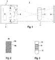
- figure 1 1 schematically shows an exemplary embodiment of the sensor arrangement 1 according to the invention for detecting sample bodies in a detection area.
- the sensor arrangement 1 comprises an optical sensor 2 whose components are arranged in a housing 3 .
- the optical sensor 2 includes an image sensor 4 with a two-dimensional, rectangular or square Arrangement of light-sensitive receiving elements.
- the image sensor 4 can be designed as a CMOS or CCD sensor.
- the image sensor 4 is preceded by receiving optics 5 forming a lens.
- the optical sensor 2 also has an illumination unit, which in the present case is formed by two transmitter units 6 which are arranged on both sides of the image sensor 4 .
- an illumination unit which in the present case is formed by two transmitter units 6 which are arranged on both sides of the image sensor 4 .
- only one transmission unit 6 can also be provided.
- a plurality of transmission units 6 can enclose the image sensor 4 in a ring shape.
- the or each sensor unit 6 advantageously consists of a light-emitting diode arrangement.
- the or each transmission unit 6 is assigned a transmission optics 7 . This ensures that the lighting unit emits diffuse light into the detection area.
- the image sensor 4 and the transmission units 6 are arranged behind a window 8 in the front wall of the housing 3 .
- the optical sensor 2 also has an evaluation unit 9, which is formed by a microcontroller or the like.
- the image sensor 4 and the transmission units 6 are connected to the evaluation unit 9 .
- the evaluation unit 9 thus controls the lighting unit.
- image signals generated by the image sensor 4 are evaluated in the evaluation unit 9, as a result of which object detection signals are generated which can be output via one or more outputs (not shown).
- the optical sensor 2 is located at an edge of the detection area.
- a textured background 10 ( figure 1 ).
- the textured background 10 has a surface with a regular arrangement of light stripes 10a and dark stripes 10b.
- the strips 10a, 10b run inclined at 45° to the horizontal.
- the stripe pattern is applied to a carrier to form the textured background 10 .
- the lighting unit of the optical sensor 2 emits light beams 11 in such a way that the textured background 10 is completely illuminated with it.
- the sample body to be detected is located in the detection area between the optical sensor and the textured background 10.
- the longitudinal axis of the sample body is oriented in the vertical direction.
- the strips 10a, 10b of the textured background 10 thus run at an angle of 45° to the longitudinal axis of the specimen.
- the sample body consists of a sample tube 12 which is closed at its open top with a cap 13 of a defined color.
- a liquid to be analyzed in particular a blood sample, is located in the sample tube 12 .
- a code 14 in the form of a barcode is applied to the sample tube 12 .
- the code segments of the barcode run in a horizontal direction and are thus inclined by 45° to the stripes 10a, 10b of the textured background 10.
- the sample body is detected in front of the textured background 10 with the optical sensor 2 , ie the sample body with the textured background 10 is recorded in an image generated with the image sensor 4 .
- the stripe pattern of the textured background 10 is formed in such a way that on the one hand it clearly differs from all structures of the sample body and on the other hand it can be resolved by the optical sensor 2 , ie it can be recognized in an image of the image sensor 4 .
- the background portion of the textured background 10 can be eliminated from an image of the image sensor 4 by algorithms integrated in the evaluation unit 9, so that only the image portion of the sample body is extracted. All relevant information of the sample body can thus be extracted from an image of the image sensor 4 in the evaluation unit 9 .
- this includes the code information in the barcode, the width and height of the sample tube 12, the presence check whether a cap 13 is present on the sample tube 12, the size and color of the cap 13. Furthermore, a recognition of the type of cap 13 and thus a Object classification possible.
- the information obtained in this way can be output by the optical sensor 2 individually or cumulatively as an object detection signal.
- an image recorded with the image sensor 4 is filtered by means of a one-dimensional filter according to the Laws method, described in: Laws, K. (1979) Texture Energy Measures. In Proceedings: Image Understanding Workshop, DARPA, Los Angeles, CA, USA, 47-51 .
- the regular static structure of the background part in the image is used by the filter adapting to this background pattern.
- the structure of the specimen does not match this background portion and can thus be separated quickly and easily from the background portion of the image.
- the pixels of the filtered image are then evaluated using the Otsu method, described in: Otsu, N. (1979).
- This binarized image is used for a BLOB (binarized large object) analysis, which is used, for example, in the Article "Development of FPGA-based realtime BLOB-analysis circuit", J. Trein. A. Schwarzbacher, B. Hoppe, K.-H. Noffz, T. Trenschel in ISSC 2007 described.
- image processing takes place in such a way that objects or object features are separated from a background or other objects.
- a BLOB or an object is defined by a set of pixels of the image that are related to each other and differ from a background.
- the BLOBs obtained with this BLOB analysis contain the information about the specimen to be detected.
- a color analysis of the sample body is carried out on the basis of color measurements, in particular in order to determine the color of the cap 13 .
- the geometry data of the sample tube 12 and the cap 13 are determined on the basis of the BLOBs.
- the barcode of the sample tube 12 is recorded using an ROI (region of interest) method. Then the code information contained in the barcode is decoded.
Description
Die Erfindung betrifft eine Sensoranordnung zur Erfassung von Probenkörpern.The invention relates to a sensor arrangement for detecting specimens.
Derartige Probenkörper sind insbesondere von Probenröhrchen gebildet, die mit Flüssigkeit befüllt und jeweils mit einer Kappe verschlossen sind. Derartige Probenröhrchen enthalten typischerweise medizinische Proben. Ein Beispiel hierfür sind mit Blutproben befüllte Probenröhrchen, die in der Blutanalyse Verwendung finden. Die Probenröhrchen werden zu Analysezwecken automatisiert unterschiedlichen Stationen zugeführt.Such test bodies are formed in particular from test tubes that are filled with liquid and each sealed with a cap. Such sample tubes typically contain medical samples. An example of this are sample tubes filled with blood samples, which are used in blood analysis. The sample tubes are automatically fed to different stations for analysis purposes.
Hierbei ist es erforderlich, die einzelnen Probenröhrchen zu erfassen und zu identifizieren, insbesondere um Verwechslungen und Fehlzuordnungen zu vermeiden.Here it is necessary to record and identify the individual sample tubes, in particular to avoid mix-ups and incorrect assignments.
Typischerweise ist auf jedem Probenröhrchen ein Code, insbesondere ein Barcode aufgebracht, der zur Probenidentifikation dient.Typically, a code, in particular a barcode, is applied to each sample tube, which is used for sample identification.
Um in einer automatisierten Anlage derartige Probenröhrchen zu erkennen, ist es bekannt, optische Sensoren einzusetzen, die typischerweise als Empfänger einen Bildsensor, das heißt eine Kamera aufweisen. Mit derartigen optischen Sensoren muss einerseits das Probenröhrchen selbst, beispielsweise durch eine Konturerfassung, und auch der Code des Probenröhrchens erkannt werden.In order to detect such sample tubes in an automated system, it is known to use optical sensors which typically have an image sensor, ie a camera, as a receiver. With such optical sensors, on the one hand the sample tube itself must be recognized, for example by contour detection, and also the code of the sample tube.
Aus der
Weiter ist bei derartigen Systemen nachteilig, dass zur Objekterkennung einerseits und zur Barcodeerkennung andererseits unterschiedliche Bilder der Kamera, die bei unterschiedlichen Beleuchtungsverhältnissen aufgenommen werden, herangezogen werden müssen.Another disadvantage of such systems is that different images of the camera, which are recorded under different lighting conditions, have to be used for object recognition on the one hand and for barcode recognition on the other hand.
Aus der
Aus der
Die
Die
Die
In
In
Der Erfindung liegt die Aufgabe zugrunde, eine Sensoranordnung bereitzustellen, mittels derer mit geringem konstruktivem Aufwand eine sichere Erkennung von Probenkörpern ermöglicht wird.The invention is based on the object of providing a sensor arrangement by means of which reliable detection of specimens is made possible with little structural effort.
Zur Lösung dieser Aufgabe sind die Merkmale des Anspruchs 1 vorgesehen. Vorteilhafte Ausführungsformen und zweckmäßige Weiterbildungen der Erfindung sind in den abhängigen Ansprüchen beschrieben.To solve this problem, the features of
Die Erfindung betrifft eine Sensoranordnung zur Erfassung von Probenröhrchen für Blutanalyse in einem Erfassungsbereich mit einem einen Bildsensor aufweisenden optischen Sensor an einem ersten Ende des Erfassungsbereichs und mit texturiertem Hintergrund an einem zweiten Ende des Erfassungsbereichs. Der texturierte Hintergrund weist eine sich von den optischen Eigenschaften des Probenröhrchens unterscheidende Musterung auf, die vom optischen Sensor in einem Bild des Bildsensors erkannt werden kann. Dabei wird ein im Erfassungsbereich vor dem texturierten Hintergrund angeordnetes Probenröhrchen mit einem darauf angebrachten Code mittels des Bildsensors erfasst. In einer Auswerteeinheit wird
- durch Filter-Algorithmen eine Abbildung des texturierten Hintergrunds aus-einem Bild des Bildsensors eliminiert und eine Abbildung des Probenröhrchens aus dem Bild des Bildsensors extrahiert
- und es werden Probenröhrchen kennzeichnende Objektfeststellungssignale und ein von Codeinformationen des Codes gebildetes Objektfeststellungssignal generiert.
- an image of the textured background is eliminated from an image of the image sensor by filter algorithms and an image of the sample tube is extracted from the image of the image sensor
- and object detection signals indicative of sample tubes and an object detection signal composed of code information of the code are generated.
Erfindungsgemäß ist der texturierte Hintergrund als optisch aktives Element in Form einer eigenen Beleuchtung ausgebildet, mittels derer die Musterung des texturierten Hintergrunds generiert wird.According to the invention, the textured background is designed as an optically active element in the form of its own lighting, by means of which the pattern of the textured background is generated.
Der Grundgedanke der Erfindung besteht darin, einen texturierten Hintergrund bereitzustellen, der einerseits vom optischen Sensor erfasst werden kann und andererseits von der optischen Struktur eindeutig unterscheidbar ist.The basic idea of the invention is to provide a textured background that can be detected by the optical sensor on the one hand and is clearly distinguishable from the optical structure on the other hand.
In der Auswerteeinheit kann daher aus einem mit dem Bildsensor des optischen Sensors aufgenommenen Bild der Hintergrundanteil eliminiert werden und so der Anteil des Bildes mit dem Probenröhrchen separat ausgewertet werden. Dies ermöglicht eine detaillierte Erfassung des Probenröhrchens als Ganzes sowie auch von Teilen hiervon oder von Strukturen auf den Probenröhrchen.In the evaluation unit, the background component can therefore be eliminated from an image recorded with the image sensor of the optical sensor, and the component of the image with the sample tube can thus be evaluated separately. This enables a detailed recording of the sample tube as a whole as well as parts thereof or structures on the sample tube.
In der Auswerteeinheit sind Algorithmen implementiert, mittels derer in einem Bild des Bildsensors der texturierte Hintergrund vom Probenröhrchen separierbar ist.Algorithms are implemented in the evaluation unit, by means of which the textured background can be separated from the sample tube in an image of the image sensor.
Der texturierte Hintergrund ist so ausgebildet, dass dessen Bildbestandteile in einem Bild des Bildsensors systematisch durch geeignete Algorithmen, wie zum Beispiel Filter-Algorithmen, eliminiert werden können. Der texturierte Hintergrund ist so beschaffen, dass dessen Bild regelmäßige statische Eigenschaften aufweist, so dass dann mit geeigneten Filteralgorithmen der Hintergrundanteil des Bildes systematisch eliminiert werden kann. Erfindungsgemäß ist der texturierte Hintergrund als optisch aktives Element ausgebildet.The textured background is designed in such a way that its image components can be systematically eliminated in an image from the image sensor using suitable algorithms, such as filter algorithms. The textured background is designed in such a way that its image has regular static properties, so that the background portion of the image can then be systematically eliminated using suitable filter algorithms. According to the invention, the textured background is designed as an optically active element.
Der texturierte Hintergrund weist eine eigene Beleuchtung auf, mittels derer die Muster des texturierten Hintergrunds generiert werden, indem die Beleuchtung beispielsweise transparente oder opake Streifen eines Streifenmusters beleuchten.The textured background has its own lighting, by means of which the patterns of the textured background are generated, for example by the lighting illuminating transparent or opaque strips of a striped pattern.
Ein wesentlicher Vorteil der erfindungsgemäßen Sensoranordnung besteht darin, dass durch den an die zu erkennenden Probenröhrchen angepassten texturierten Hintergrund nicht nur das Probenröhrchen selbst, sondern auch auf diesem aufgebrachte Codes erfasst werden können, und zwar innerhalb eines einzigen Bildes, welches mit dem Bildsensor aufgenommen wird. Damit können Probenröhrchen sehr genau und gleichzeitig auch sehr schnell mit der erfindungsgemäßen Sensoranordnung erfasst werden.A significant advantage of the sensor arrangement according to the invention is that, thanks to the textured background adapted to the sample tube to be recognized, not only the sample tube itself but also codes applied to it can be detected, specifically within a single image recorded with the image sensor. In this way, sample tubes can be detected very precisely and at the same time very quickly with the sensor arrangement according to the invention.
Demzufolge können in der Auswerteeinheit anhand der Bildauswertung kumulativ oder einzeln unterschiedliche Objektfeststellungssignale generiert werden, die an die jeweiligen Applikationsanforderungen angepasst sein können.Consequently, different object detection signals, which can be adapted to the respective application requirements, can be generated cumulatively or individually in the evaluation unit based on the image evaluation.
So kann das Objektfeststellungsignal als Anwesenheitssignal ausgebildet sein, dessen Signalzustände angeben, ob sich ein Probenröhrchen im Erfassungsbereich befindet oder nicht.The object detection signal can thus be in the form of a presence signal, the signal states of which indicate whether or not a sample tube is in the detection area.
Weiterhin kann das Objektfeststellungssignal von Geometrieinformationen oder Farbinformationen oder Komponenten hiervon gebildet sein.Furthermore, the object detection signal can be formed from geometry information or color information or components thereof.
Erfindungsgemäß ist an dem Probenröhrchen ein Code angebracht, wobei das Objektfeststellungssignal von Codeinformationen des Codes gebildet ist.According to the invention, a code is attached to the sample tube, the object detection signal being formed from code information of the code.
Schließlich ist das Objektfeststellungssignal ein Objektklassifikationssignal.Finally, the object detection signal is an object classification signal.
Gemäß einer besonders vorteilhaften Ausgestaltung der Erfindung ist das Probenröhrchen mit einer Kappe verschlossen, wobei als Objektfeststellungssignal die Höhe und/oderAccording to a particularly advantageous embodiment of the invention, the sample tube is closed with a cap, the height and/or the object detection signal being used
Breite des Probenröhrchens, und/oder die Anwesenheit, Dimension und/oder die Farbe der Kappe ausgegeben wird.width of the sample tube, and/or the presence, dimension and/or color of the cap is output.
Der optische Sensor der Sensoranordnung ist vorteilhaft derart ausgebildet, dass der Bildsensor eine matrixförmige Anordnung von lichtempfindlichen Empfangselementen aufweist.The optical sensor of the sensor arrangement is advantageously designed in such a way that the image sensor has a matrix-like arrangement of light-sensitive receiving elements.
Insbesondere ist der Bildsensor von einem CMOS- oder CCD-Sensor gebildet. Weiter vorteilhaft weist der optische Sensor eine Beleuchtungseinheit auf, mittels derer der texturierte Hintergrund angeleuchtet ist.In particular, the image sensor is formed by a CMOS or CCD sensor. The optical sensor also advantageously has an illumination unit, by means of which the textured background is illuminated.
Dabei strahlt die Beleuchtungseinheit diffuses Licht ab.The lighting unit emits diffuse light.
Die Erfindung wird im Folgenden anhand der Zeichnungen erläutert. Es zeigen:
- Figur 1:
- Schematische Darstellung eines Ausführungsbeispiels der erfindungsgemäßen Sensoranordnung.
- Figur 2:
- Draufsicht auf den texturierten Hintergrund der Sensoranordnung gemäß
Figur 1 - Figur 3:
- Draufsicht auf ein Probenröhrchen, welches mit der Sensoranordnung gemäß
Figur 1 erfassbar ist.
- Figure 1:
- Schematic representation of an embodiment of the sensor arrangement according to the invention.
- Figure 2:
- Top view of the textured background according to the sensor array
figure 1 . - Figure 3:
- Top view of a sample tube, which with the sensor arrangement according to
figure 1 is detectable.
Die Sensoranordnung 1 umfasst einen optischen Sensor 2, dessen Komponenten in einem Gehäuse 3 angeordnet sind. Der optische Sensor 2 umfasst einen Bildsensor 4 mit einer zweidimensionalen, rechteckigen oder quadratischen Anordnung von lichtempfindlichen Empfangselementen. Der Bildsensor 4 kann als CMOS- oder CCD-Sensor ausgebildet sein. Dem Bildsensor 4 ist eine ein Objektiv bildende Empfangsoptik 5 vorgeordnet.The
Der optische Sensor 2 weist weiterhin eine Beleuchtungseinheit auf, die im vorliegenden Fall von zwei Sendeeinheiten 6 gebildet ist, die beidseits des Bildsensors 4 angeordnet sind. Prinzipiell kann auch nur eine Sendeeinheit 6 vorgesehen sein. Ebenso können mehrere Sendeeinheiten 6 den Bildsensor 4 ringförmig umschließen. Die oder jede Sensoreinheit 6 besteht vorteilhaft aus einer Leuchtdiodenanordnung. Der oder jeder Sendeeinheit 6 ist eine Sendeoptik 7 zugeordnet. Mit dieser wird erreicht, dass die Beleuchtungseinheit diffuses Licht in den Erfassungsbereich abstrahlt. Der Bildsensor 4 und die Sendeeinheiten 6 sind hinter einem Fenster 8 in der Frontwand des Gehäuses 3 angeordnet.The
Der optische Sensor 2 weist weiterhin eine Auswerteeinheit 9 auf, die von einem Micocontroller oder dergleichen gebildet ist. Der Bildsensor 4 und die Sendeeinheiten 6 sind an die Auswerteeinheit 9 angeschlossen. Die Auswerteeinheit 9 steuert somit die Beleuchtungseinheit. Zudem werden in der Auswerteeinheit 9 vom Bildsensor 4 generierte Bildsignale ausgewertet, wodurch Objektfeststellungssignale generiert werden, die über einen oder mehrere nicht dargestellte Ausgänge ausgegeben werden können.The
Der optische Sensor 2 befindet sich an einem Rand des Erfassungsbereichs. Am anderen Ende des Erfassungsbereichs befindet sich ein texturierter Hintergrund 10 (
Die Beleuchtungseinheit des optischen Sensors 2 emittiert Lichtstrahlen 11 derart, dass damit der texturierte Hintergrund 10 vollständig ausgeleuchtet wird.The lighting unit of the
Der zu detektierende Probenkörper befindet sich im Erfassungsbereich zwischen dem optischen Sensor und dem texturierten Hintergrund 10. Die Längsachse des Probenkörpers ist dabei in vertikaler Richtung orientiert. Die Streifen 10a, 10b des texturierten Hintergrunds 10 verlaufen somit um 45° geneigt zur Längsachse des Probenkörpers.The sample body to be detected is located in the detection area between the optical sensor and the
Der Probenkörper besteht im vorliegenden Fall aus einem Probenröhrchen 12, das an seiner offenen Oberseite mit einer Kappe 13 definierter Farbe verschlossen ist. Im Probenröhrchen 12 befindet sich eine zu analysierende Flüssigkeit, insbesondere eine Blutprobe. Wie
Mit dem optischen Sensor 2 wird der Probenkörper vor dem texturierten Hintergrund 10 erfasst, das heißt in einem mit dem Bildsensor 4 generierten Bild ist der Probenkörper mit dem texturierten Hintergrund 10 aufgenommen.The sample body is detected in front of the
Das Streifenmuster des texturierten Hintergrunds 10 ist so ausgebildet, dass es sich einerseits von allen Strukturen des Probenkörpers eindeutig unterscheidet und andererseits vom optischen Sensor 2 aufgelöst, das heißt in einem Bild des Bildsensors 4 erkannt werden kann.The stripe pattern of the
Durch in der Auswerteeinheit 9 integrierte Algorithmen kann der Hintergrundanteil des texturierten Hintergrunds 10 aus einem Bild des Bildsensors 4 eliminiert werden, so dass allein der Bildanteil des Probenkörpers extrahiert wird. Damit können aus einem Bild des Bildsensors 4 in der Auswerteeinheit 9 alle relevanten Informationen des Probenkörpers extrahiert werden. Im vorliegenden Fall gehören hierzu die Codeinformationen im Barcode, die Breite und Höhe des Probenröhrchens 12, die Anwesenheitsprüfung, ob eine Kappe 13 auf dem Probenröhrchen 12 vorhanden ist, die Dimension und Farbe der Kappe 13. Weiterhin ist eine Erkennung des Typs der Kappe 13 und damit eine Objektklassifikation möglich. Die so gewonnenen Informationen können einzeln oder kumulativ als Objektfeststellungssignal vom optischen Sensor 2 ausgegeben werden.The background portion of the
Im Folgenden wird eine typische Bildauswertung anhand von in der Auswerteeinheit 9 implementierten Algorithmen erläutert.A typical image evaluation is explained below using algorithms implemented in the
Zunächst erfolgt eine Filterung eines mit dem Bildsensor 4 aufgenommenen Bildes mittels eines eindimensionalen Filters gemäß der Methode von Laws, beschrieben in:
Bei dieser Filterung wird die reguläre statische Struktur des Hintergrundanteils im Bild ausgenutzt, indem der Filter eine Anpassung an dieses Hintergrundmuster vornimmt. Die Struktur des Probenkörpers passt nicht zu diesem Hintergrundanteil und kann so einfach und schnell vom Hintergrundanteil des Bildes separiert werden.With this filtering, the regular static structure of the background part in the image is used by the filter adapting to this background pattern. The structure of the specimen does not match this background portion and can thus be separated quickly and easily from the background portion of the image.
Im dem so gefilterten Bild erscheinen die Bildanteile des Hintergrundanteils als weiße Flächen.In the image filtered in this way, the image parts of the background appear as white areas.
Mit einer anschließenden Median-Filterung werden Rausch-Anteile im Bild eliminiert.With a subsequent median filtering, noise components in the image are eliminated.
Anschließend erfolgt eine Schwellwertbewertung der Pixel des so gefilterten Bildes nach der Methode von Otsu, beschrieben in:
Mit dieser Schwellwertbewertung werden dunkle Pixel von hellen Pixeln getrennt, das heißt es wird ein binarisiertes Bild erhalten, in welchem die dunklen Pixel die Kontur des Probenkörpers sind.The pixels of the filtered image are then evaluated using the Otsu method, described in:
With this threshold evaluation, dark pixels are separated from light pixels, ie a binarized image is obtained in which the dark pixels are the contour of the sample body.
Anhand dieses binarisierten Bildes erfolgt eine BLOB- (Binarized large object) Analyse, die beispielsweise in dem
Die mit dieser BLOB-Analyse erhaltenden BLOBs enthalten die Informationen über den zu detektierenden Probenkörper. Anhand von Farbmessungen erfolgt eine Farbanalyse des Probenkörpers, insbesondere um die Farbe der Kappe 13 zu bestimmen.The BLOBs obtained with this BLOB analysis contain the information about the specimen to be detected. A color analysis of the sample body is carried out on the basis of color measurements, in particular in order to determine the color of the
Weiterhin werden anhand der BLOBs die Geometriedaten des Probenröhrchens 12 und der Kappe 13 bestimmt.Furthermore, the geometry data of the
Schließlich wird mit einer ROI-(region of interest) Methode der Barcode des Probenröhrchens 12 erfasst. Dann wird die im Barcode enthaltene Codeinformation dekodiert.Finally, the barcode of the
- (1)(1)
- Sensoranordnungsensor arrangement
- (2)(2)
- Optischer Sensoroptical sensor
- (3)(3)
- GehäuseHousing
- (4)(4)
- Bildsensorimage sensor
- (5)(5)
- Empfangsoptikreceiving optics
- (6)(6)
- Sendeeinheittransmitter unit
- (7)(7)
- Sendeoptiktransmission optics
- (8)(8th)
- Fensterwindow
- (9)(9)
- Auswerteeinheitevaluation unit
- (10)(10)
- texturierter Hintergrundtextured background
- (10a)(10a)
- helle Streifenbright stripes
- (10b)(10b)
- dunkle Streifendark stripes
- (11)(11)
- Lichtstrahlenrays of light
- (12)(12)
- ProbenröhrchenSample Tube
- (13)(13)
- Kappecap
- (14)(14)
- Codecode
Claims (7)
- A sensor arrangement (1) for detecting specimen tubes (12) for blood analysis in a detection area with an optical sensor (2) having an image sensor (4) at a first end of the detection area and with a textured background (10) at a second end of the detection area, wherein the textured background (10) has a patterning which differs from the optical properties of the specimen tube (12), which can be detected by the optical sensor (2) in an image of the image sensor (4) and wherein a specimen tube (12) arranged in the detection region in front of the textured background (10) with a code applied thereto is detected by means of the image sensor (4) and wherein in an evaluation unit (9)• filter algorithms eliminate an image of the textured background from an image of the image sensor (4) and extract an image of the specimen tube (12) from the image of the image sensor (4); and• object detection signals identifying specimen tubes (12) and an object detection signal formed by code information of the code are generated,characterised in that the textured background (10) is formed as an optically active element in the form of its own illumination by means of which the patterning of the textured background is generated.
- A sensor arrangement according to claim 1, characterised in that the object detection signal is designed as a presence signal whose signal states indicate whether or not a specimen tube (12) is located in the detection range.
- A sensor arrangement according to one of claims 1 or 2, characterised in that the object detection signal is formed by geometry information or colour information of the specimen tube (12) or components thereof.
- A sensor arrangement according to one of claims 1 to 3, characterised in that the object detection signal is an object classification signal.
- A sensor arrangement according to one of claims 1 to 3, characterised in that the specimen tube (12) is closed with a cap (13), wherein the height and/or width of the specimen tube (12), and/or the presence, dimension and/or colour of the cap (13) is output as an object detection signal.
- A sensor arrangement according to one of claims 1 to 5, characterised in that the image sensor (4) has a matrix-shaped arrangement of light-sensitive receiving elements.
- A sensor arrangement according to claim 6, characterised in that the image sensor (4) is formed by a CMOS or CCD sensor.
Applications Claiming Priority (1)
| Application Number | Priority Date | Filing Date | Title |
|---|---|---|---|
| US14/842,875 US9547784B1 (en) | 2015-09-02 | 2015-09-02 | Sensor arrangement |
Publications (2)
| Publication Number | Publication Date |
|---|---|
| EP3139309A1 EP3139309A1 (en) | 2017-03-08 |
| EP3139309B1 true EP3139309B1 (en) | 2022-08-03 |
Family
ID=55755355
Family Applications (1)
| Application Number | Title | Priority Date | Filing Date |
|---|---|---|---|
| EP16164601.3A Active EP3139309B1 (en) | 2015-09-02 | 2016-04-11 | Sensor arrangement for the detection of specimen containers |
Country Status (2)
| Country | Link |
|---|---|
| US (1) | US9547784B1 (en) |
| EP (1) | EP3139309B1 (en) |
Families Citing this family (3)
| Publication number | Priority date | Publication date | Assignee | Title |
|---|---|---|---|---|
| US9967924B2 (en) * | 2014-02-25 | 2018-05-08 | James Heczko | Package for storing consumable product, induction heating apparatus for heating package and system including same |
| EP3538870A4 (en) * | 2016-11-14 | 2019-11-27 | Siemens Healthcare Diagnostics Inc. | Methods and apparatus for characterizing a specimen using pattern illumination |
| DE202018100794U1 (en) | 2018-02-14 | 2018-04-27 | Leuze Electronic Gmbh + Co Kg | sensor arrangement |
Family Cites Families (8)
| Publication number | Priority date | Publication date | Assignee | Title |
|---|---|---|---|---|
| US6546356B1 (en) * | 2000-05-01 | 2003-04-08 | Genovation Inc. | Body part imaging method |
| US20060067572A1 (en) * | 2004-09-14 | 2006-03-30 | Tattile, L.L.C. | Object imaging system |
| US7499581B2 (en) * | 2005-02-10 | 2009-03-03 | Forhealth Technologies, Inc. | Vision system to calculate a fluid volume in a container |
| US8170322B2 (en) * | 2006-03-22 | 2012-05-01 | Jadak Llc | Optical imaging system and method using a reflective background |
| WO2009097263A1 (en) | 2008-01-28 | 2009-08-06 | Siemens Heathcare Diagnostics Inc. | Method and apparatus for auxiliary illumination for detecting an object |
| US8170271B2 (en) | 2008-06-25 | 2012-05-01 | Jadak Llc | System and method for test tube and cap identification |
| US9372486B2 (en) * | 2011-12-21 | 2016-06-21 | Deka Products Limited Partnership | System, method, and apparatus for monitoring, regulating, or controlling fluid flow |
| DE202013102120U1 (en) * | 2013-05-15 | 2013-06-06 | Leuze Electronic Gmbh + Co. Kg | sensor arrangement |
-
2015
- 2015-09-02 US US14/842,875 patent/US9547784B1/en active Active
-
2016
- 2016-04-11 EP EP16164601.3A patent/EP3139309B1/en active Active
Non-Patent Citations (2)
| Title |
|---|
| KENNETH I LAWS: "Texture Energy Measures", IMAGE UNDERSTANDING WORKSHOP, 1 January 1979 (1979-01-01), Los Angeles, CA, USA, pages 47 - 51, XP055659669 * |
| LAWS K I: "Rapid texture identification", PROCEEDINGS OF THE SOCIETY OF PHOTO-OPTICAL INSTRUMENTATION ENGINEERING,, vol. 238, 1 January 1980 (1980-01-01), pages 376 - 380, XP009126287, ISSN: 0361-0748 * |
Also Published As
| Publication number | Publication date |
|---|---|
| US9547784B1 (en) | 2017-01-17 |
| EP3139309A1 (en) | 2017-03-08 |
Similar Documents
| Publication | Publication Date | Title |
|---|---|---|
| EP3537339A2 (en) | Camera and method for detecting image data | |
| EP2569757B1 (en) | Movement analysis and/or tracking system | |
| EP3139309B1 (en) | Sensor arrangement for the detection of specimen containers | |
| WO2003060483A1 (en) | Method and device for the analysis of body fluids | |
| DE102009000003A1 (en) | Camera arrangement for detecting a wheel condition of a vehicle window | |
| DE202006020599U1 (en) | Optical detection of moving objects and device | |
| DE102017116758B4 (en) | Method and device for scanning surfaces with a stereo camera | |
| EP2605041A1 (en) | Handheld range finder | |
| DE2518746A1 (en) | AUTOMATIC FOCUSING SYSTEM | |
| EP2619550B1 (en) | Sensor for monitoring a medium | |
| DE102021109078B3 (en) | Camera device and method for capturing a moving stream of objects | |
| EP2619551B1 (en) | Sensor for monitoring a medium | |
| EP3910547B1 (en) | Detection of moving objects | |
| DE102008007731B4 (en) | Method and device for identifying and authenticating objects | |
| DE202012103003U1 (en) | Apparatus for measuring sample determination, measuring apparatus and kit with sample modules | |
| DE202015100438U1 (en) | Opto-electronic sensor for the acquisition of object information | |
| DE102007059050B4 (en) | Method for operating an optoelectronic switch and optoelectronic switch | |
| DE102010062959A1 (en) | position sensing | |
| WO2014082797A1 (en) | Method and device for determining three-dimensional raised structures on a surface of a document | |
| EP1744141A2 (en) | Method and device for testing a hollow fibre bundle | |
| DE102015116568A1 (en) | Method for analyzing an object with an image acquisition unit in a factory or process automation and an image recording device for analyzing an object in the factory or process automation | |
| DE202014105781U1 (en) | Fingerprint scanner | |
| DE10232682B4 (en) | Method and apparatus for non-magnetically identifying living things and using the same | |
| DE102012105100B4 (en) | Optical sensor | |
| CH706779A2 (en) | Sensor arrangement for the optical detection of attached to sample tube and sample carrier codes. |
Legal Events
| Date | Code | Title | Description |
|---|---|---|---|
| PUAI | Public reference made under article 153(3) epc to a published international application that has entered the european phase |
Free format text: ORIGINAL CODE: 0009012 |
|
| STAA | Information on the status of an ep patent application or granted ep patent |
Free format text: STATUS: THE APPLICATION HAS BEEN PUBLISHED |
|
| AK | Designated contracting states |
Kind code of ref document: A1 Designated state(s): AL AT BE BG CH CY CZ DE DK EE ES FI FR GB GR HR HU IE IS IT LI LT LU LV MC MK MT NL NO PL PT RO RS SE SI SK SM TR |
|
| AX | Request for extension of the european patent |
Extension state: BA ME |
|
| STAA | Information on the status of an ep patent application or granted ep patent |
Free format text: STATUS: REQUEST FOR EXAMINATION WAS MADE |
|
| 17P | Request for examination filed |
Effective date: 20170315 |
|
| RBV | Designated contracting states (corrected) |
Designated state(s): AL AT BE BG CH CY CZ DE DK EE ES FI FR GB GR HR HU IE IS IT LI LT LU LV MC MK MT NL NO PL PT RO RS SE SI SK SM TR |
|
| STAA | Information on the status of an ep patent application or granted ep patent |
Free format text: STATUS: EXAMINATION IS IN PROGRESS |
|
| 17Q | First examination report despatched |
Effective date: 20200211 |
|
| STAA | Information on the status of an ep patent application or granted ep patent |
Free format text: STATUS: EXAMINATION IS IN PROGRESS |
|
| REG | Reference to a national code |
Ref country code: DE Ref legal event code: R079 Ref document number: 502016015119 Country of ref document: DE Free format text: PREVIOUS MAIN CLASS: G06K0009200000 Ipc: G06K0007100000 |
|
| RIC1 | Information provided on ipc code assigned before grant |
Ipc: G06V 30/224 20220101ALI20220311BHEP Ipc: G06V 20/66 20220101ALI20220311BHEP Ipc: G06V 10/25 20220101ALI20220311BHEP Ipc: G06K 7/10 20060101AFI20220311BHEP |
|
| GRAP | Despatch of communication of intention to grant a patent |
Free format text: ORIGINAL CODE: EPIDOSNIGR1 |
|
| STAA | Information on the status of an ep patent application or granted ep patent |
Free format text: STATUS: GRANT OF PATENT IS INTENDED |
|
| INTG | Intention to grant announced |
Effective date: 20220503 |
|
| GRAS | Grant fee paid |
Free format text: ORIGINAL CODE: EPIDOSNIGR3 |
|
| GRAA | (expected) grant |
Free format text: ORIGINAL CODE: 0009210 |
|
| STAA | Information on the status of an ep patent application or granted ep patent |
Free format text: STATUS: THE PATENT HAS BEEN GRANTED |
|
| AK | Designated contracting states |
Kind code of ref document: B1 Designated state(s): DE |
|
| RBV | Designated contracting states (corrected) |
Designated state(s): DE |
|
| REG | Reference to a national code |
Ref country code: DE Ref legal event code: R096 Ref document number: 502016015119 Country of ref document: DE |
|
| REG | Reference to a national code |
Ref country code: DE Ref legal event code: R097 Ref document number: 502016015119 Country of ref document: DE |
|
| PLBE | No opposition filed within time limit |
Free format text: ORIGINAL CODE: 0009261 |
|
| STAA | Information on the status of an ep patent application or granted ep patent |
Free format text: STATUS: NO OPPOSITION FILED WITHIN TIME LIMIT |
|
| 26N | No opposition filed |
Effective date: 20230504 |
|
| PGFP | Annual fee paid to national office [announced via postgrant information from national office to epo] |
Ref country code: DE Payment date: 20230412 Year of fee payment: 8 |