EP3139221A1 - Autonomous l1-adaptive controller with exact pole placement - Google Patents
Autonomous l1-adaptive controller with exact pole placement Download PDFInfo
- Publication number
- EP3139221A1 EP3139221A1 EP16182394.3A EP16182394A EP3139221A1 EP 3139221 A1 EP3139221 A1 EP 3139221A1 EP 16182394 A EP16182394 A EP 16182394A EP 3139221 A1 EP3139221 A1 EP 3139221A1
- Authority
- EP
- European Patent Office
- Prior art keywords
- signal
- state
- predictor
- feedback
- modeling
- Prior art date
- Legal status (The legal status is an assumption and is not a legal conclusion. Google has not performed a legal analysis and makes no representation as to the accuracy of the status listed.)
- Granted
Links
- 230000003044 adaptive effect Effects 0.000 claims abstract description 18
- 238000000034 method Methods 0.000 claims abstract description 17
- 230000006978 adaptation Effects 0.000 claims abstract description 14
- RZVHIXYEVGDQDX-UHFFFAOYSA-N 9,10-anthraquinone Chemical compound C1=CC=C2C(=O)C3=CC=CC=C3C(=O)C2=C1 RZVHIXYEVGDQDX-UHFFFAOYSA-N 0.000 claims abstract description 12
- 238000010586 diagram Methods 0.000 description 9
- 230000000694 effects Effects 0.000 description 9
- 238000005259 measurement Methods 0.000 description 9
- 239000013598 vector Substances 0.000 description 8
- 230000003321 amplification Effects 0.000 description 4
- 230000001934 delay Effects 0.000 description 4
- 238000003199 nucleic acid amplification method Methods 0.000 description 4
- 238000013461 design Methods 0.000 description 3
- 230000008901 benefit Effects 0.000 description 2
- 230000008859 change Effects 0.000 description 2
- 230000001276 controlling effect Effects 0.000 description 2
- 230000001419 dependent effect Effects 0.000 description 2
- 239000011159 matrix material Substances 0.000 description 2
- 230000001105 regulatory effect Effects 0.000 description 2
- 238000013459 approach Methods 0.000 description 1
- 238000004364 calculation method Methods 0.000 description 1
- 230000000295 complement effect Effects 0.000 description 1
- 238000010276 construction Methods 0.000 description 1
- 238000001514 detection method Methods 0.000 description 1
- 238000011161 development Methods 0.000 description 1
- 238000006073 displacement reaction Methods 0.000 description 1
- 230000005284 excitation Effects 0.000 description 1
- 238000012986 modification Methods 0.000 description 1
- 230000004048 modification Effects 0.000 description 1
- 230000008569 process Effects 0.000 description 1
- 230000004044 response Effects 0.000 description 1
- 238000004088 simulation Methods 0.000 description 1
- 238000012546 transfer Methods 0.000 description 1
Images


Classifications
-
- G—PHYSICS
- G05—CONTROLLING; REGULATING
- G05B—CONTROL OR REGULATING SYSTEMS IN GENERAL; FUNCTIONAL ELEMENTS OF SUCH SYSTEMS; MONITORING OR TESTING ARRANGEMENTS FOR SUCH SYSTEMS OR ELEMENTS
- G05B13/00—Adaptive control systems, i.e. systems automatically adjusting themselves to have a performance which is optimum according to some preassigned criterion
- G05B13/02—Adaptive control systems, i.e. systems automatically adjusting themselves to have a performance which is optimum according to some preassigned criterion electric
- G05B13/04—Adaptive control systems, i.e. systems automatically adjusting themselves to have a performance which is optimum according to some preassigned criterion electric involving the use of models or simulators
- G05B13/048—Adaptive control systems, i.e. systems automatically adjusting themselves to have a performance which is optimum according to some preassigned criterion electric involving the use of models or simulators using a predictor
-
- B—PERFORMING OPERATIONS; TRANSPORTING
- B64—AIRCRAFT; AVIATION; COSMONAUTICS
- B64C—AEROPLANES; HELICOPTERS
- B64C9/00—Adjustable control surfaces or members, e.g. rudders
-
- G—PHYSICS
- G05—CONTROLLING; REGULATING
- G05B—CONTROL OR REGULATING SYSTEMS IN GENERAL; FUNCTIONAL ELEMENTS OF SUCH SYSTEMS; MONITORING OR TESTING ARRANGEMENTS FOR SUCH SYSTEMS OR ELEMENTS
- G05B13/00—Adaptive control systems, i.e. systems automatically adjusting themselves to have a performance which is optimum according to some preassigned criterion
- G05B13/02—Adaptive control systems, i.e. systems automatically adjusting themselves to have a performance which is optimum according to some preassigned criterion electric
- G05B13/04—Adaptive control systems, i.e. systems automatically adjusting themselves to have a performance which is optimum according to some preassigned criterion electric involving the use of models or simulators
- G05B13/042—Adaptive control systems, i.e. systems automatically adjusting themselves to have a performance which is optimum according to some preassigned criterion electric involving the use of models or simulators in which a parameter or coefficient is automatically adjusted to optimise the performance
Definitions
- the invention relates to a predictor device for a control device, for controlling at least one manipulated variable of a controlled system, which has at least one controllable by means of the manipulated variable actuator and detectable by a sensor state with at least one controlled variable. Furthermore, the regulating device has an adaptation device, which is designed to generate a matched uncertainty signal and an unmatched uncertainty signal, and an L1-adaptive control device.
- the predictor device has a state modeling device for estimating a behavior of the controlled system and is designed to output an estimated state having at least one estimated variable. Furthermore, the invention relates to an aircraft with such a control device for flight control.
- the invention also relates to an L1 adaptive control method using an L1 adaptive control device, an adaptation device that generates a matched uncertainty signal and an unmatched uncertainty signal, and to a predictor device having a state modeling device. Moreover, the invention relates to an aircraft with a control device for flight control, which is designed to carry out such a method.
- sensors are additionally provided which can measure a state, for example a rate of rotation or a speed of the aircraft.
- the controlled system in the case of the aircraft so the aircraft with its associated flight dynamics, has certain uncertainties that complicate a generally valid constant parameterization of previously used basic control devices, for example, have a PID controller.
- basic control devices can not adequately respond to changes in the characteristics of the controlled system, in particular to changes in a characteristic of the uncertainties which lead to a behavior that differs from a nominal behavior.
- the L1 adaptive controller may be provided to limit the effects of deviations from this nominal range or uncertainties on the control loop.
- the invention is based on the object of further developing a predictor device of the type mentioned at the outset such that the construction of a control device in which the predictor device is used can be simplified.
- a predictor device which in addition to the features mentioned at least a first feedback means for providing a first feedback signal from an output of the state modeling device for feeding into a first combination means, wherein a measured and / or estimated actuator state in the first combining means is fed, wherein the state modeling means is adapted for receiving an unmatched input signal at an unmatched input, wherein the matched uncertainty signal is fed to the combination with the further signals in the first combination means, wherein the first combination means is designed to combine the injected signals and wherein the signal obtainable by the first combination means is a matched input signal for feeding into a matched input of the state model forming device.
- Such a predictor device makes it possible to perform a complete control alone by means of the adaptive control device and to dispense with a separate baseline control device. In particular, this makes it possible to carry out an exact pole assignment for the control loop. This has the effect that, despite its simplified structure, the control thereby achieved has both robustness against uncertainties and a desired dynamic.
- the predictor means may comprise a second feedback means for providing a second feedback signal from the output signal for input to a second combiner, the unmatched uncertainty signal being fed to the second combiner, and the signal obtainable by the second combiner means an unmatched input signal for feeding into an unmatched input the state modeling device forms.
- the predictor means may comprise a transducer modeling means for estimating the actuator state based on the manipulated variable.
- the predictor device can also be used if a direct measurement of an actuator state is not possible or not provided.
- the converter modeling device can be advantageously designed for modeling actuators and / or sensors of the controlled system. This ensures that the transducer characteristics of the actuators and the sensors are included in the estimation the behavior of the controlled system and thus taken into account in the implementation of the scheme.
- the first feedback device and / or the second feedback device may have a multiplication device. This makes it possible to tune the effect of the feedback of the output signal of the state modeling device and thus the properties of the entire control loop.
- the signal obtainable by the first combination device may be obtainable from addition of the matched uncertainty signal and the output signal of the converter modeling device or at least one selected state variable of the actuator state and a subtraction of the first feedback signal.
- the signal obtainable by the second combination means may be obtainable from a subtraction of the second feedback signal from the unmatched uncertainty signal.
- the state modeling device is designed for modeling a flight dynamics of an aircraft.
- the predictor device and the control device formed therewith can be used for flight control in aircraft.
- an aircraft according to claim 10 which has a control device for flight control, which has a prediction device according to the invention.
- an L1 adaptive control method using an L1 adaptive controller, an adapter that generates estimates for a matched uncertainty signal and an unmatched uncertainty signal, and a predictor having a state modeling device with the steps Return of an output signal of the state modeling device into a first feedback device, converting the output signal into a first feedback signal by the first feedback device and generating a matched input signal for the state modeling device by means of the first combination device by adding the matched uncertainty signal and a measured or estimated actuator state and subtracting the first feedback signal.
- Such a method also has the above-mentioned advantages, in particular that an exact pole assignment in the control loop is possible. This ensures that the control loop has both robustness against uncertainties and a desired dynamics.
- the method comprises the steps of returning the output of the state modeling means to a second feedback means, converting the output signal into a second feedback signal by the second feedback means, generating an unmatched input signal to the state modeling means by the second combining means by subtracting the second feedback signal from the unmatched uncertainty signal.
- the method may further comprise the step of estimating an actuator state by means of a transducer modeling device that generates an output signal from a manipulated variable that forms an estimate of state variables of the actuator state.
- Fig. 1 to 3 show a predictor device 18 according to a first embodiment of the present invention for use in a closed-loop control device 10 as shown in FIG Fig. 2 is shown.
- the control loop has a controlled system 12, an adaptation device 36 and an L1-adaptive control device 38 via the predictor device 18.
- control device 10 is used to generate suitable manipulated variables u cmd the controlled system 12.
- the controlled system 12 for example, as in Fig. 3 shown may have an aircraft 50, has a state which usually has a plurality of state variables and which can be influenced by actuators 14 controllable by the manipulated variables u cmd .
- the controlled system 12 has sensors 16, which can measure the state variables of the aircraft 50.
- the result of these measurements is a state variable x, which can be scaled or expressed as a vector depending on the application.
- the state quantity x when representing a plurality of state quantities, can be expressed as a vector having a plurality of individual sizes as its components. The same applies to other variables, for example the manipulated variable u cmd .
- the predictor device 18 is used to estimate an estimated variable x , which is obtained from a state variable u and an uncertainty signal ⁇ .
- the state quantity u may be scalar if it has only one component and may be a vector if it has multiple components.
- the representable as a vector signal uncertainty ⁇ for example, has two components, in particular a matched signal uncertainty ⁇ m and an unmatched signal uncertainty ⁇ microns.
- the matched uncertainty signal ⁇ m and the unmatched uncertainty signal ⁇ um are provided by the adaptation device 36.
- the term "matched” refers to the fact that the signal designated in this way influences the states or the state variable x in the same way as actuators of the control loop. In contrast, the term denotes "unmatched" signals which, in a manner complementary to the physical actuators, influence the states x of the system.
- the actuators 14 can adjust an elevator based on the manipulated variable u cmd , the actual deflection (state variable) u of which is measured, this measured value being transferred to the predictor device 18.
- the predictor device 18 generates an estimated variable x from the deflection u and the uncertainty signal ⁇ estimated by the adaptation device 36.
- the predictor 18 includes a replica of the controlled system 12. Such a replica can be performed both by electronic or mechanical components as well as by purely algorithmic simulation of the properties of the controlled system 12.
- the model of the aircraft 50 is contained in a state modeling device 22, the model of the sensors 16 in a sensor modeling device 54.
- a prediction error is x calculated by subtracting the controlled variable x from the estimated value x.
- the prediction error x is transferred to the adaptation device 36, which generates the uncertainty signal ⁇ therefrom.
- the uncertainty signal ⁇ is, as already described above, transferred to the predictor 18 as an additional input value.
- the uncertainty signal ⁇ is also passed as an input signal to the L1-adaptive control device 38.
- the L1-adaptive control device 38 generates from the uncertainty signal ⁇ and a reference variable y cmd the manipulated variable u cmd , which in turn is transferred to the controlled system 12.
- the state modeling device 22 has two inputs for receiving two input signals. One of the inputs picks up a matched input signal, the other of the inputs picks up an unmatched input signal.
- the state modeling device 22 For use in a flight control, the state modeling device 22 generates, for example, an estimated angle of attack ⁇ and an estimated pitch rate q , which together form the estimated variable x as the output 32 of the state modeling device 22.
- the estimate may in such a case be written as a vector of the individual values of the estimate x , for example as follows: ⁇ ⁇ q ⁇
- a first feedback device 26 and a second feedback device 24 are provided whose inputs are respectively fed with the estimated angle of attack ⁇ and the estimated pitch rate q, ie the output signal 32 of the state modeling device 22 , To simplify the illustration only, the output signal 32 is shown in some figures only by a single line.
- the first feedback device 26 generates a first feedback signal 42, which is fed together with the matched uncertainty signal ⁇ m and the manipulated variable u into a first combination device 30, which from the injected signals ⁇ m , u ,, 42 a matched input signal 46 for the state modeling device 22nd generated, for example, by the injected signals are added, with feedback signals (feedback), in this case, the first feedback signal 42, with a negative sign in the addition received (negative feedback), ie deducted from the sum of the two other signals ⁇ m , u become.
- the second feedback device 24 generates a second feedback signal 34, which is fed together with the unmatched uncertainty signal ⁇ um to a second combination device 44, which consists of the injected signals ⁇ um , 34 generates an unmatched input signal 40 in the same manner as the first combination means 30.
- the second feedback signal 34 is a negative feedback and enters the addition in the second combination means 44 with a negative sign.
- the first feedback device 26 and the second feedback device 24 are formed, for example, by matrix or vector multipliers, which linearly link the signals fed into the feedback device 26, 24 to the respective output signal or feedback signal 42, 34.
- a similar control device 10 is shown as in the Fig. 1 to 3 , In this case, however, it is not possible in the controlled system 12 'to measure the state of the actuators 14, so that the in Fig. 4 predictor means shown 18 as a replica of the process 12 ', for example, in addition to the state modeling means 22 and the sensor modeling means 54 has a model of the actuators 14 in the form of a Aktormodelltechniks worn 52 u cmd from the command value, an output signal 28 which corresponds to an estimated state variable u corresponding to the Manipulated variable u of the first embodiment generates. The output signal 28 thus replaces the measured state quantity u. Thus, no measurement of the state quantity u is necessary. However, the output signal 28 is merely an estimated state quantity û .
- the associated controlled system 12 ' is in Fig. 7 shown.
- FIG. 12 shows another simplified embodiment of the predictor device 18 for use in flight control, for example for an F-16 aircraft having a transducer modeling device 20 and a state modeling device 22.
- the actuator modeling device 52 and the sensor modeling device 54 are combined. This is usually possible because these components are LTI components.
- the converter modeling device 20 receives the manipulated variable u cmd as an input signal and generates from this an output signal 28, which models the effect of actuators and sensors in the controlled system 12.
- Fig. 6 and 8th show a control loop in which a predictor 18 according to the second or third embodiment is usable.
- the controlled system 12 ' is not designed to measure a manipulated variable u .
- Fig. 8 shows a closed loop with a control device 10 for flight control, which has a predictor 18 according to the second or third embodiment.
- the reference variable y cmd is formed in the present example by the desired angle of attack ⁇ cmd , the manipulated variable u cmd by a position vector ⁇ cmd .
- the matched and unmatched branches of the adaptation device 36 and the L1 adaptive control device 38 are shown separately and identified by exemplary transfer functions.
- a linear input-output response is desired because this results in predictable behavior for a human operator and structural aircraft components can be sized accordingly.
- the desired behavior of the closed loop is therefore linear, for example.
- a linear reference model can be designed using a linear approximation of the aircraft's short-term dynamics and feedback of the outputs.
- eigenstructure default can be used as a design strategy.
- Eigen Modellvorgabe actor dynamics and sensor delays can be explicitly included in the calculation.
- the amplification factor of the feedback k ref T can be parameterized by known methods, for example eigenstructure specification using the short-term, the actuator and the delay dynamics.
- the pre-control gain h ref is calculated so that a stationary, precise guidance sequence is achieved.
- the goal of the autonomous control by the control device 10 without using a basic control is to achieve good control performance in both the nominal (ordinary) and non-nominal conditions in the reference model shown above. Since the intrinsic aircraft dynamics is non-linear even under nominal conditions, the controller 10 must compensate for these nonlinearities to set the desired linear behavior. At the same time, it must be guaranteed that the deviation from the reference dynamic due to non-nominal behavior of the controlled system remains within an acceptable range.
- a simple idea for the parameterization of an appropriate predictor means 18 would be to design a holistic state space model for sensor delays, actuator dynamics and the desired short-term dynamics.
- the estimated value x would actuator and sensor delay states include a measurement of the corresponding controlled variables, x would be necessary to allow the piecewise constant L1 control architecture to compute the estimation error x. Since in the real world such measurement results, for example for the delay, are often not available, this approach is avoided.
- All signals and / or quantities communicated between the devices 18, 20, 22, 24, 26, 30, 36, 38, 44, 48, 52, 54 may be both scalars and vectors.
- the ordinary L1 adaptive control architecture consists of three different main components: a predictor 18, an adapter 36 (adaptation law) and an L1 adaptive controller 38 (control law).
- the present invention modifies the dynamics of the predictor 18 so that a feedback term is added to the ordinary adaptive control signal by means of the feedback means 26, 24 and the combining means 30, 44, for the purpose of pole assignment, for example.
- This modification is achieved in that the state of the state modeling device 22, or the estimated variable x , is fed back to matched and unmatched inputs of the state modeling device 22, as described in FIGS Fig. 1 . 4 . 5 and 8th is shown.
- the dynamics of the state modeling device 22 is chosen to match the nominal dynamics of the controlled system 12.
- the additional feedback according to the present invention leads to an excitation of the estimation error, which in turn leads to a change in the control variable 12 passed control variable.
- this change in the manipulated variable can be designed such that it acts like a normal linear feedback of the states of the controlled system. In this way, a precise eigenvalue placement can be ensured.
- the robustness of the control against uncertainties of the controlled system can be combined with the achievement of the desired dynamics for the nominal case.
- the present invention accomplishes this without the use of a conventional linear baseline controller. This leads to a simplification of the controller design and offers a comparable performance.
- the technical benefit of the present invention is particularly given for the development and planning of agile aircraft.
- the adaptive control system shows its strengths, especially in the fast Adjusting the dynamics are.
- the position of the poles determines the stability and instability of a missile and is therefore of great relevance, even for any certification.
- An exact positioning / predictability of the poles is relevant because it provides both robustness and desired dynamics.
- Use cases of the invention can range from manned missiles to unmanned large and small drones. In particular, good predictable flight characteristics are achieved by the invention with a simple structure.
- control device 12 10 control device 12, 12 ', 12 "controlled system 14 actor 16 sensor 18 predictor device 20 transducer modeling device 22 state modeling device 24 first return device 26 second return device 28, û output (the transducer modeling means 20) 30 first combination device 32 output signal (the state modeling device 22) 34 first feedback signal 36 adaptation device 38 L1 adaptive control device 40 unmatched input signal 42 second feedback signal 44 second combination device 46 matched input signal 48 error detection device 50 aircraft 52 actuator modeling device 54 sensor modeling device u cmd manipulated variable ⁇ cmd manipulated variable x controlled variable ⁇ q controlled variable x estimated value ⁇ ⁇ q ⁇ estimated value x estimation error ⁇ m matched uncertainty signal (estimate) ⁇ to unmatched uncertainty signal (estimate) y cmd guide size
Abstract
Die Erfindung betrifft eine Prädiktoreinrichtung für eine Regelungsvorrichtung, zur Regelung wenigstens einer Stellgröße einer Regelstrecke, die wenigstens einen mittels der Stellgröße steuerbaren Aktor und einen von einem Sensor erfassbaren Zustand mit wenigstens einer Regelgröße aufweist. Des Weiteren weist die Prädiktoreinrichtung eine Adaptionseinrichtung und eine L1-adaptive Regelungseinrichtung auf. Die Prädiktoreinrichtung weist eine Zustandsmodellierungseinrichtung zum Schätzen eines Verhaltens der Regelstrecke auf und ist zur Ausgabe eines geschätzten Zustands mit wenigstens einer Schätzgröße ausgebildet. Des Weiteren betrifft die Erfindung ein Luftfahrzeug mit einer derartigen Regelungsvorrichtung zur Flugregelung. Die Erfindung betrifft auch ein L1-adaptives Regelungsverfahren unter Verwendung einer L1-adaptiven Regelungseinrichtung, einer Adaptionseinrichtung, die ein matched Unsicherheitssignal und ein unmatched Unsicherheitssignal erzeugt, sowie einer Prädiktoreinrichtung, die eine Zustandsmodellierungseinrichtung aufweist. Darüber hinaus betrifft die Erfindung ein Luftfahrzeug mit einer Regelungsvorrichtung zur Flugregelung, die zur Durchführung eines derartigen Verfahrens ausgebildet ist.The invention relates to a predictor device for a control device, for controlling at least one manipulated variable of a controlled system, which has at least one controllable by means of the manipulated variable actuator and detectable by a sensor state with at least one controlled variable. Furthermore, the predictor device has an adaptation device and an L1-adaptive control device. The predictor device has a state modeling device for estimating a behavior of the controlled system and is designed to output an estimated state having at least one estimated variable. Furthermore, the invention relates to an aircraft with such a control device for flight control. The invention also relates to an L1 adaptive control method using an L1 adaptive control device, an adaptation device that generates a matched uncertainty signal and an unmatched uncertainty signal, and to a predictor device having a state modeling device. Moreover, the invention relates to an aircraft with a control device for flight control, which is designed to carry out such a method.
Description
Die Erfindung betrifft eine Prädiktoreinrichtung für eine Regelungsvorrichtung, zur Regelung wenigstens einer Stellgröße einer Regelstrecke, die wenigstens einen mittels der Stellgröße steuerbaren Aktor und einen von einem Sensor erfassbaren Zustand mit wenigstens einer Regelgröße aufweist. Des Weiteren weist die Regelungseinrichtung eine Adaptionseinrichtung, die zum Erzeugen eines matched Unsicherheitssignals und eines unmatched Unsicherheitssignals ausgebildet ist, und eine L1-adaptive Regelungseinrichtung auf. Die Prädiktoreinrichtung weist eine Zustandsmodellierungseinrichtung zum Schätzen eines Verhaltens der Regelstrecke auf und ist zur Ausgabe eines geschätzten Zustands mit wenigstens einer Schätzgröße ausgebildet. Des Weiteren betrifft die Erfindung ein Luftfahrzeug mit einer derartigen Regelungsvorrichtung zur Flugregelung. Die Erfindung betrifft auch ein L1-adaptives Regelungsverfahren unter Verwendung einer L1-adaptiven Regelungseinrichtung, einer Adaptionseinrichtung, die ein matched Unsicherheitssignal und ein unmatched Unsicherheitssignal erzeugt, sowie einer Prädiktoreinrichtung, die eine Zustandsmodellierungseinrichtung aufweist. Darüber hinaus betrifft die Erfindung ein Luftfahrzeug mit einer Regelungsvorrichtung zur Flugregelung, die zur Durchführung eines derartigen Verfahrens ausgebildet ist.The invention relates to a predictor device for a control device, for controlling at least one manipulated variable of a controlled system, which has at least one controllable by means of the manipulated variable actuator and detectable by a sensor state with at least one controlled variable. Furthermore, the regulating device has an adaptation device, which is designed to generate a matched uncertainty signal and an unmatched uncertainty signal, and an L1-adaptive control device. The predictor device has a state modeling device for estimating a behavior of the controlled system and is designed to output an estimated state having at least one estimated variable. Furthermore, the invention relates to an aircraft with such a control device for flight control. The invention also relates to an L1 adaptive control method using an L1 adaptive control device, an adaptation device that generates a matched uncertainty signal and an unmatched uncertainty signal, and to a predictor device having a state modeling device. Moreover, the invention relates to an aircraft with a control device for flight control, which is designed to carry out such a method.
Es gibt Bestrebungen, Prädiktoreinrichtungen der eingangs genannten Art insbesondere in Luftfahrzeugen anzuwenden, in denen sie mit einer Adaptionseinrichtung und einer L1-adaptiven Regelungseinrichtung zu einer Regelungsvorrichtung zur Regelung von Stellgrößen des Luftfahrzeugs, beispielsweise Schub oder Stellung von Höhen- und/oder Seitenruder, verbunden sind. Um den Effekt der Regelung der Stellgrößen des Luftfahrzeugs feststellen zu können, sind darüber hinaus Sensoren vorgesehen, welche einen Zustand, beispielsweise eine Drehrate oder eine Geschwindigkeit des Luftfahrzeugs, messen können.There are efforts to apply predictor devices of the type mentioned in particular in aircraft, in which they are connected to an adaptation device and a L1-adaptive control device to a control device for controlling manipulated variables of the aircraft, such as thrust or position of elevator and / or rudder , In order to be able to determine the effect of regulating the manipulated variables of the aircraft, sensors are additionally provided which can measure a state, for example a rate of rotation or a speed of the aircraft.
Die Regelstrecke, im Fall des Luftfahrzeugs also das Luftfahrzeug mit seiner zugehörigen Flugdynamik, weist gewisse Unsicherheiten auf, die eine allgemein gültige konstante Parametrisierung von bisher verwendeten Basisregelungseinrichtungen, die beispielsweise einen PID-Regler aufweisen, erschweren. Insbesondere können derartige Basisregelungseinrichtungen auf Änderungen der Eigenschaften der Regelstrecke, insbesondere auf Veränderungen einer Charakteristik der Unsicherheiten, die zu einem Verhalten führen, das sich von einem nominellen Verhalten unterscheidet, nicht adäquat reagieren. Zusätzlich dazu kann daher die L1-adaptive Regelungseinrichtung vorgesehen sein, um die Auswirkungen von Abweichungen von diesem nominellen Bereich beziehungsweise von Unsicherheiten auf den Regelkreis zu begrenzen.The controlled system, in the case of the aircraft so the aircraft with its associated flight dynamics, has certain uncertainties that complicate a generally valid constant parameterization of previously used basic control devices, for example, have a PID controller. In particular, such basic control devices can not adequately respond to changes in the characteristics of the controlled system, in particular to changes in a characteristic of the uncertainties which lead to a behavior that differs from a nominal behavior. In addition, therefore, the L1 adaptive controller may be provided to limit the effects of deviations from this nominal range or uncertainties on the control loop.
Die Erfindung beruht auf der Aufgabe, eine Prädiktoreinrichtung der eingangs genannten Art so weiterzubilden, dass der Aufbau einer Regelungsvorrichtung, in welcher die Prädiktoreinrichtung eingesetzt wird, vereinfacht werden kann.The invention is based on the object of further developing a predictor device of the type mentioned at the outset such that the construction of a control device in which the predictor device is used can be simplified.
Zur Lösung der Aufgabe wird eine Prädiktoreinrichtung gemäß Patentanspruch 1 vorgeschlagen, die zusätzlich zu den eingangs genannten Merkmalen wenigstens eine erste Rückführeinrichtung zur Bereitstellung eines ersten Rückführsignals aus einem Ausgangssignal der Zustandsmodellierungseinrichtung zur Einspeisung in eine erste Kombinationseinrichtung aufweist, wobei ein gemessener und/oder geschätzter Aktorzustand in die erste Kombinationseinrichtung eingespeist ist, wobei die Zustandsmodellierungseinrichtung zur Aufnahme eines unmatched Eingangssignals an einem unmatched Eingang ausgebildet ist, wobei das matched Unsicherheitssignal zur Kombination mit den weiteren Signalen in die erste Kombinationseinrichtung eingespeist ist, wobei die erste Kombinationseinrichtung zur Kombination der eingespeisten Signale ausgebildet ist und wobei das durch die erste Kombinationseinrichtung erhaltbare Signal ein matched Eingangssignal zur Einspeisung in einen matched Eingang der Zustandsmodellierungseinrichtung bildet.To solve the problem, a predictor device according to
Eine derartige Prädiktoreinrichtung erlaubt es, eine vollständige Regelung alleine mittels der adaptiven Regelungsvorrichtung durchzuführen und auf eine separate Baseline-Regelungseinrichtung zu verzichten. Insbesondere ist es dadurch möglich, eine exakte Polzuweisung für den Regelkreis durchzuführen. Dies bewirkt, dass die dadurch erreichte Regelung trotz ihres vereinfachten Aufbaus sowohl Robustheit gegenüber Unsicherheiten als auch eine gewünschte Dynamik aufweist.Such a predictor device makes it possible to perform a complete control alone by means of the adaptive control device and to dispense with a separate baseline control device. In particular, this makes it possible to carry out an exact pole assignment for the control loop. This has the effect that, despite its simplified structure, the control thereby achieved has both robustness against uncertainties and a desired dynamic.
Vorteilhafte Ausgestaltungen der Erfindung sind Gegenstand der Unteransprüche.Advantageous embodiments of the invention are the subject of the dependent claims.
Die Prädiktoreinrichtung kann eine zweite Rückführeinrichtung zur Bereitstellung eines zweiten Rückführsignals aus dem Ausgangssignal zur Einspeisung in eine zweite Kombinationseinrichtung aufweisen, wobei das unmatched Unsicherheitssignal in die zweite Kombinationseinrichtung eingespeist ist und wobei das durch die zweite Kombinationseinrichtung erhaltbare Signal ein unmatched Eingangssignal zur Einspeisung in einen unmatched Eingang der Zustandsmodellierungseinrichtung bildet.The predictor means may comprise a second feedback means for providing a second feedback signal from the output signal for input to a second combiner, the unmatched uncertainty signal being fed to the second combiner, and the signal obtainable by the second combiner means an unmatched input signal for feeding into an unmatched input the state modeling device forms.
Durch diese doppelte Rückführung von matched- und unmatched-Signalen und deren Kombination mit matched und unmatched Unsicherheitssignalen kann, insbesondere durch geeignete Wahl von Verstärkungsfaktoren der ersten und zweiten Rückführeinrichtung, ein Regelungseffekt erreicht werden, der wie eine gewöhnliche lineare Rückführung der Zustände der Regelstrecke wirkt. Auf diese Weise wird eine präzise Eigenwertplatzierung sichergestellt.By this double feedback of matched and unmatched signals and their combination with matched and unmatched uncertainty signals, a control effect can be achieved, in particular by a suitable choice of gain factors of the first and second feedback device, which acts like a normal linear feedback of the states of the controlled system. This ensures accurate eigenvalue placement.
Die Prädiktoreinrichtung kann eine Wandlermodellierungseinrichtung zur Schätzung des Aktorzustands aufgrund der Stellgröße aufweisen. Dadurch kann die Prädiktoreinrichtung auch eingesetzt werden, wenn eine unmittelbare Messung eines Aktorzustands nicht möglich oder nicht vorgesehen ist.The predictor means may comprise a transducer modeling means for estimating the actuator state based on the manipulated variable. As a result, the predictor device can also be used if a direct measurement of an actuator state is not possible or not provided.
Die Wandlermodellierungseinrichtung kann vorteilhaft zur Modellierung von Aktoren und/oder Sensoren der Regelstrecke ausgebildet sein. Dadurch wird erreicht, dass die Wandlereigenschaften der Aktoren und der Sensoren in die Schätzung des Verhaltens der Regelstrecke mit aufgenommen und somit bei der Durchführung der Regelung mit berücksichtigt werden.The converter modeling device can be advantageously designed for modeling actuators and / or sensors of the controlled system. This ensures that the transducer characteristics of the actuators and the sensors are included in the estimation the behavior of the controlled system and thus taken into account in the implementation of the scheme.
Die erste Rückführeinrichtung und/oder die zweite Rückführeinrichtung können eine Multiplikationseinrichtung aufweisen. Dadurch ist es möglich, die Wirkung der Rückführung des Ausgangssignals der Zustandsmodellierungseinrichtung und somit die Eigenschaften des gesamten Regelkreises abzustimmen.The first feedback device and / or the second feedback device may have a multiplication device. This makes it possible to tune the effect of the feedback of the output signal of the state modeling device and thus the properties of the entire control loop.
Das durch die erste Kombinationseinrichtung erhaltbare Signal kann aus einer Addition des matched Unsicherheitssignals und des Ausgangssignals der Wandlermodellierungseinrichtung oder wenigstens einer ausgewählten Zustandsgröße des Aktorzustands sowie einer Subtraktion des ersten Rückführsignals erhaltbar sein.The signal obtainable by the first combination device may be obtainable from addition of the matched uncertainty signal and the output signal of the converter modeling device or at least one selected state variable of the actuator state and a subtraction of the first feedback signal.
Das durch die zweite Kombinationseinrichtung erhaltbare Signal kann aus einer Subtraktion des zweiten Rückführsignals von dem unmatched Unsicherheitssignal erhaltbar sein.The signal obtainable by the second combination means may be obtainable from a subtraction of the second feedback signal from the unmatched uncertainty signal.
Vorteilhaft ist die Zustandsmodellierungseinrichtung zur Modellierung einer Flugdynamik eines Luftfahrzeugs ausgebildet. Dadurch sind die Prädiktoreinrichtung und die Regelungsvorrichtung, die damit gebildet ist, zur Flugregelung in Luftfahrzeugen einsetzbar.Advantageously, the state modeling device is designed for modeling a flight dynamics of an aircraft. As a result, the predictor device and the control device formed therewith can be used for flight control in aircraft.
Die Aufgabe wird des Weiteren durch ein Luftfahrzeug gemäß Patentanspruch 10 gelöst, das eine Regelungseinrichtung zur Flugregelung aufweist, die eine lösungsgemäße Prädiktoreinrichtung aufweist.The object is further achieved by an aircraft according to
Darüber hinaus wird die Aufgabe auch durch ein L1-adaptives Regelungsverfahren gemäß Patentanspruch 11 unter Verwendung einer L1-adaptiven Regelungseinrichtung, einer Adaptionseinrichtung, die Schätzungen für ein matched Unsicherheitssignal und ein unmatched Unsicherheitssignal erzeugt, sowie einer Prädiktoreinrichtung, die eine Zustandsmodellierungseinrichtung aufweist, mit den Schritten Rückführung eines Ausgangssignals der Zustandsmodellierungseinrichtung in eine erste Rückführeinrichtung, Umsetzen des Ausgangssignals in ein erstes Rückführsignal durch die erste Rückführeinrichtung und Erzeugen eines matched Eingangssignals für die Zustandsmodellierungseinrichtung mittels der ersten Kombinationseinrichtung durch Addition des matched Unsicherheitssignals und eines gemessenen oder geschätzten Aktorzustands sowie Subtraktion des ersten Rückführsignals gelöst.In addition, the object is also provided by an L1 adaptive control method according to claim 11 using an L1 adaptive controller, an adapter that generates estimates for a matched uncertainty signal and an unmatched uncertainty signal, and a predictor having a state modeling device with the steps Return of an output signal of the state modeling device into a first feedback device, converting the output signal into a first feedback signal by the first feedback device and generating a matched input signal for the state modeling device by means of the first combination device by adding the matched uncertainty signal and a measured or estimated actuator state and subtracting the first feedback signal.
Ein derartiges Verfahren weist ebenfalls die oben genannten Vorteile auf, insbesondere, dass eine exakte Polzuweisung in dem Regelkreis möglich ist. Dadurch wird erreicht, dass der Regelkreis sowohl Robustheit gegenüber Unsicherheiten als auch eine gewünschte Dynamik aufweist.Such a method also has the above-mentioned advantages, in particular that an exact pole assignment in the control loop is possible. This ensures that the control loop has both robustness against uncertainties and a desired dynamics.
Vorteilhafte Ausgestaltungen des Verfahrens sind Gegenstand der Unteransprüche 12 und 13.Advantageous embodiments of the method are the subject of the
Vorteilhaft weist das Verfahren die Schritte Rückführung des Ausgangssignals der Zustandsmodellierungseinrichtungen in eine zweite Rückführeinrichtung, Umsetzen des Ausgangssignals in ein zweites Rückführsignal durch die zweite Rückführeinrichtung, Erzeugen eines unmatched Eingangssignals für die Zustandsmodellierungseinrichtung mittels der zweiten Kombinationseinrichtung durch Subtraktion des zweiten Rückführsignals von dem unmatched Unsicherheitssignal auf.Advantageously, the method comprises the steps of returning the output of the state modeling means to a second feedback means, converting the output signal into a second feedback signal by the second feedback means, generating an unmatched input signal to the state modeling means by the second combining means by subtracting the second feedback signal from the unmatched uncertainty signal.
Durch diese doppelte Rückführung von matched- und unmatched-Signalen und deren Kombination mit matched und unmatched Unsicherheitssignalen kann, insbesondere durch geeignete Wahl von Verstärkungsfaktoren der ersten und zweiten Rückführeinrichtung ein Regelungseffekt erreicht werden, der wie eine gewöhnliche lineare Rückführung der Zustände der Regelstrecke wirkt. Auf diese Weise kann eine präzise Eigenwertplatzierung sichergestellt werden.As a result of this double feedback of matched and unmatched signals and their combination with matched and unmatched uncertainty signals, a control effect can be achieved, in particular by a suitable choice of amplification factors of the first and second feedback devices, which acts like a normal linear feedback of the states of the controlled system. In this way, a precise eigenvalue placement can be ensured.
Das Verfahren kann darüber hinaus den Schritt Schätzen eines Aktorzustands mittels einer Wandlermodellierungseinrichtung, die aus einer Stellgröße ein Ausgangssignal erzeugt, das eine Schätzung von Zustandsgrößen des Aktorzustands bildet, aufweisen.The method may further comprise the step of estimating an actuator state by means of a transducer modeling device that generates an output signal from a manipulated variable that forms an estimate of state variables of the actuator state.
Darüber hinaus wird die Aufgabe durch ein Luftfahrzeug mit einer Regelungsvorrichtung zur Flugregelung, die zur Durchführung des genannten Verfahrens gemäß Patentanspruch 10 ausgebildet ist, gelöst.In addition, the object is achieved by an aircraft with a control device for flight control, which is designed to carry out the aforementioned method according to
Die Erfindung wird nachfolgend anhand eines Ausführungsbeispiels näher erläutert, das in den Zeichnungen lediglich schematisch gezeigt ist. Es zeigen im Einzelnen:
- Fig. 1
- eine schematische Blockdarstellung einer Prädiktoreinrichtung gemäß einer ersten Ausführungsform der vorliegenden Erfindung;
- Fig. 2
- eine schematische Blockdarstellung eines Regelkreises mit einer Regelungseinrichtung, die eine Prädiktoreinrichtung gemäß einer ersten Ausführungsform der vorliegenden Erfindung aufweist;
- Fig. 3
- eine schematische Blockdarstellung einer Regelstrecke aus dem Regelkreis gemäß
Fig. 2 ; - Fig. 4
- eine schematische Blockdarstellung einer Prädiktoreinrichtung gemäß einer zweiten Ausführungsform der vorliegenden Erfindung;
- Fig. 5
- eine schematische Blockdarstellung einer Prädiktoreinrichtung gemäß einer dritten Ausführungsform der vorliegenden Erfindung;
- Fig. 6
- eine schematische Blockdarstellung wie in
Fig. 2 mit einer Regelungseinrichtung, die eine Prädiktoreinrichtung gemäß einer zweiten oder dritten Ausführungsform der vorliegenden Erfindung aufweist; - Fig. 7
- eine schematische Blockdarstellung einer Regelstrecke zur Verwendung mit einer Prädiktoreinrichtung gemäß
Fig. 4 ; - Fig. 8
- eine verfeinerte schematische Blockdarstellung wie in
Fig. 6 ; und - Fig. 9
- ein Referenzmodell für eine Regelstrecke in Form eines Luftfahrzeugs zur Parametrisierung einer Prädiktoreinrichtung.
- Fig. 1
- a schematic block diagram of a predictor according to a first embodiment of the present invention;
- Fig. 2
- a schematic block diagram of a control loop with a control device having a predictor device according to a first embodiment of the present invention;
- Fig. 3
- a schematic block diagram of a controlled system from the control loop according to
Fig. 2 ; - Fig. 4
- a schematic block diagram of a predictor according to a second embodiment of the present invention;
- Fig. 5
- a schematic block diagram of a predictor according to a third embodiment of the present invention;
- Fig. 6
- a schematic block diagram as in
Fig. 2 a control device having a predictor device according to a second or third embodiment of the present invention; - Fig. 7
- a schematic block diagram of a controlled system for use with a predictor according to
Fig. 4 ; - Fig. 8
- a refined schematic block diagram as in
Fig. 6 ; and - Fig. 9
- a reference model for a controlled system in the form of an aircraft for the parameterization of a predictor device.
Die in
Die Prädiktoreinrichtung 18 dient der Abschätzung einer Schätzgröße x̂, die aus einer Zustandsgröße u und einem Unsicherheitssignal σ̂ gewonnen wird. Die Zustandsgröße u kann skalar sein, wenn sie lediglich eine Komponente aufweist und kann ein Vektor sein, wenn sie mehrere Komponenten aufweist. Das als Vektor darstellbare Unsicherheitssignal σ̂ weist beispielsweise zwei Komponenten, insbesondere ein matched Unsicherheitssignal σ̂m und ein unmatched Unsicherheitssignal σ̂um auf. Das matched Unsicherheitssignal σ̂m und das unmatched Unsicherheitssignal σ̂um werden von der Adaptionseinrichtung 36 bereitgestellt. Der Begriff "matched" bezieht sich darauf, dass das Signal, das derart bezeichnet ist, auf gleiche Art und Weise die Zustände beziehungsweise die Zustandsgröße x beeinflusst wie Aktoren des Regelkreises. Im Gegensatz dazu bezeichnet der Begriff "unmatched" Signale, die auf zu den physikalischen Aktoren komplementäre Art und Weise die Zustände x des Systems beeinflussen.The
In
Die Prädiktoreinrichtung 18 erzeugt aus der Auslenkung u und dem durch die Adaptionseinrichtung 36 geschätzten Unsicherheitssignal σ̂ eine Schätzgröße x̂. Zu diesem Zweck enthält die Prädiktoreinrichtung 18 eine Nachbildung der Regelstrecke 12. Eine derartige Nachbildung kann sowohl durch elektronische oder mechanische Komponenten als auch durch rein algorithmische Nachbildung der Eigenschaften der Regelstrecke 12 durchgeführt werden. In dem vorliegenden Fall weist die Prädiktoreinrichtung 18 beispielsweise ein Modell des Luftfahrzeugs 50 sowie der Sensoren 16 auf. Das Modell des Luftfahrzeugs 50 ist in einer Zustandsmodellierungseinrichtung 22, das Modell der Sensoren 16 in einer Sensormodellierungseinrichtung 54 enthalten.The
Mittels einer Fehlerermittlungseinrichtung 48 wird ein Prädiktionsfehler x̃ durch Subtraktion der Regelgröße x von der Schätzgröße x̂ errechnet. Der Prädiktionsfehler x̃ wird an die Adaptionseinrichtung 36 übergeben, die daraus das Unsicherheitssignal σ̂ erzeugt. Das Unsicherheitssignal σ̂ wird, wie bereits oben beschrieben, als zusätzlicher Eingangswert an die Prädiktoreinrichtung 18 übergeben.By means of an
Das Unsicherheitssignal σ̂ wird darüber hinaus als Eingangssignal an die L1-adaptive Regelungseinrichtung 38 übergeben. Die L1-adaptive Regelungseinrichtung 38 erzeugt aus dem Unsicherheitssignal σ̂ und einer Führungsgröße ycmd die Stellgröße ucmd , die wiederum an die Regelstrecke 12 übergeben wird.The uncertainty signal σ is also passed as an input signal to the L1-
Die Zustandsmodellierungseinrichtung 22 weist zwei Eingänge zur Aufnahme von zwei Eingangssignalen auf. Einer der Eingänge nimmt ein matched Eingangssignal, der andere der Eingänge ein unmatched Eingangssignal auf. Zur Verwendung in einer Flugregelung erzeugt die Zustandsmodellierungseinrichtung 22 beispielsweise einen geschätzten Anstellwinkel α̂ und eine geschätzte Nickrate q̂, die gemeinsam die Schätzgröße x̂ als Ausgangssignal 32 der Zustandsmodellierungeinrichtung 22 bilden. Die Schätzgröße kann in einem derartigen Fall als Vektor der Einzelwerte der Schätzgröße x̂ geschrieben werden, beispielsweise folgendermaßen: ![]()
![]()
Zur Rückführung der Schätzgröße x̂ der Zustandsmodellierungseinrichtung 22 an deren matched und unmatched Eingang sind eine erste Rückführeinrichtung 26 und eine zweite Rückführeinrichtung 24 vorgesehen, deren Eingänge jeweils mit dem geschätzten Anstellwinkel α̂ und der geschätzten Nickrate q, also dem Ausgangssignal 32 der Zustandsmodellierungseinrichtung 22, gespeist werden. Ausschließlich um die Darstellung zu vereinfachen ist das Ausgangssignal 32 in einigen Figuren lediglich durch eine einzige Linie dargestellt.In order to return the estimated variable x of the
Die erste Rückführeinrichtung 26 erzeugt ein erstes Rückführsignal 42, das zusammen mit dem matched Unsicherheitssignal σ̂m und der Stellgröße u in eine erste Kombinationseinrichtung 30 eingespeist wird, die aus den eingespeisten Signalen σ̂m , u, ,42 ein matched Eingangssignal 46 für die Zustandsmodellierungseinrichtung 22 erzeugt, beispielsweise indem die eingespeisten Signale addiert werden, wobei Rückführsignale (Feedback), in diesem Fall das erste Rückführsignal 42, mit einem negativen Vorzeichen in die Addition eingehen (negatives Feedback), also von der Summe der beiden anderen Signale σ̂m , u abgezogen werden.The
Die zweite Rückführeinrichtung 24 erzeugt ein zweites Rückführsignal 34, das zusammen mit dem unmatched Unsicherheitssignal σ̂um in eine zweite Kombinationseinrichtung 44 eingespeist wird, die aus den eingespeisten Signalen σ̂um , 34 ein unmatched Eingangssignal 40 in derselben Weise erzeugt, wie die erste Kombinationseinrichtung 30. Das zweite Rückführsignal 34 ist ein negatives Feedback und geht mit einem negativen Vorzeichen in die Addition in der zweiten Kombinationseinrichtung 44 ein.The
Die erste Rückführeinrichtung 26 und die zweite Rückführeinrichtung 24 sind beispielsweise durch Matrizen- oder Vektormultiplikationseinrichtungen gebildet, welche die in die Rückführeinrichtung 26, 24 eingespeisten Signale miteinander linear zu dem jeweiligen Ausgangssignal beziehungsweise Rückführsignal 42, 34 verknüpfen.The
In
Die Wandlermodellierungseinrichtung 20 nimmt als Eingangssignal die Stellgröße ucmd auf und erzeugt aus dieser ein Ausgangssignal 28, das den Effekt von Aktoren und Sensoren in der Regelstrecke 12 modelliert.The
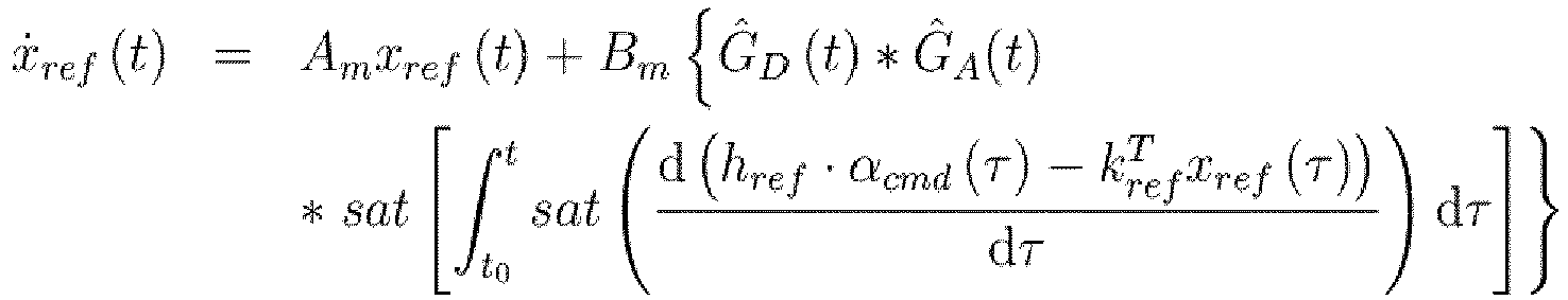
Für Anwendungen in nicht autonom geflogenen Luftfahrzeugen wird generell ein lineares Eingangs-Ausgangs-Verhalten gewünscht, da dies für einen menschlichen Bediener zu einem vorhersehbaren Verhalten führt und strukturelle Luftfahrzeugkomponenten entsprechend dimensioniert werden können. Das gewünschte Verhalten des geschlossenen Regelkreises ist daher beispielsweise linear. Wie das Beispiel in ![]()
![]()
![]()
![]()
![]()
![]()
Ziel der autonomen Regelung durch die Regelungsvorrichtung 10 ohne Verwendung einer Basisregelung ist es, in dem oben gezeigten Referenzmodell sowohl unter nominellen (gewöhnlichen) als auch nicht nominellen Bedingungen eine gute Regelungsgüte zu erreichen. Da die intrinsische Luftfahrzeugdynamik selbst unter nominalen Bedingungen nichtlinear ist, muss die Regelungsvorrichtung 10 diese Nichtlinearitäten kompensieren, um das gewünschte lineare Verhalten einzustellen. Gleichzeitig muss garantiert sein, dass die Abweichung von der Referenzdynamik aufgrund von nicht-nominellem Verhalten der Regelstrecke in einem akzeptablen Bereich bleibt.The goal of the autonomous control by the
Die bekannte L1-Regelungsarchitektur wurde für diese Regelungsaufgabe erweitert. Da Sensorverzögerungen und Aktordynamik, auch umfassend Sättigung, bei Betrachtung eines realen Luftfahrzeugs nicht vernachlässigbar sind, wurden diese Effekte ebenfalls in der Prädiktoreinrichtung 18 berücksichtigt. Diese Effekte zu vernachlässigen würde zu einer Prädiktoreinrichtung 18 führen, die von der tatsächlichen Regelstrecke wesentlich abweicht und könnte zu einem unvorhersehbaren Regelkreisverhalten führen, beispielsweise wenn die Aktoren in Sättigung sind.The well-known L1 control architecture has been extended for this control task. Since sensor delays and actuator dynamics, including saturation, are not negligible when considering a real aircraft, these effects were also taken into account in the
Eine einfache Idee für die Parametrisierung einer angemessenen Prädiktoreinrichtung 18 wäre es, ein ganzheitliches Zustandsraummodell für Sensorverzögerungen, Aktordynamik und die gewünschte Kurzzeitdynamik zu entwerfen. Da in diesem Fall die Schätzgröße x̂ Aktor- und Sensorverzögerungszustände umfassen würde, wäre eine Messung der zugehörigen Regelgrößen x notwendig, um es der stückweise konstanten L1-Regelungsarchitektur zu erlauben, den Schätzfehler x zu berechnen. Da in der realen Welt derartige Messergebnisse, beispielsweise für die Verzögerung, oftmals nicht verfügbar sind, wird dieser Ansatz vermieden.A simple idea for the parameterization of an appropriate predictor means 18 would be to design a holistic state space model for sensor delays, actuator dynamics and the desired short-term dynamics. In this case, since the estimated value x would actuator and sensor delay states include a measurement of the corresponding controlled variables, x would be necessary to allow the piecewise constant L1 control architecture to compute the estimation error x. Since in the real world such measurement results, for example for the delay, are often not available, this approach is avoided.
Die in 
Alle zwischen den Einrichtungen 18, 20, 22, 24, 26, 30, 36, 38, 44, 48, 52, 54 übermittelten Signale und/oder Größen können sowohl Skalare als auch Vektoren sein.All signals and / or quantities communicated between the
Die gewöhnliche L1-adaptive Regelungsarchitektur besteht aus drei unterschiedlichen Hauptkomponenten: einer Prädiktoreinrichtung 18, einer Adaptionseinrichtung 36 (Adaptionsgesetz) und einer L1-adaptiven Regelungseinrichtung 38 (Regelgesetz). Die vorliegende Erfindung modifiziert die Dynamik der Prädiktoreinrichtung 18 so, dass mittels der Rückführeinrichtungen 26, 24 und der Kombinationseinrichtungen 30, 44 ein Rückführungsausdruck zu dem gewöhnlichen adaptiven Regelsignal beispielsweise zum Zweck der Polzuweisung hinzugefügt wird. Diese Modifikation wird dadurch erreicht, dass der Zustand der Zustandsmodellierungseinrichtung 22, beziehungsweise die Schätzgröße x̂, an matched und unmatched Eingänge der Zustandsmodellierungseinrichtung 22 rückgeführt wird, wie es in den
Gewöhnlich wird die Dynamik der Zustandsmodellierungseinrichtung 22 so gewählt, dass sie mit der nominalen Dynamik der Regelstrecke 12 übereinstimmt. Die zusätzliche Rückführung gemäß der vorliegenden Erfindung führt zu einer Anregung des Schätzfehlers, was wiederum zu einer Veränderung der an die Regelstrecke 12 weitergegebenen Stellgröße führt. Durch Wahl der Verstärkungsfaktoren der ersten und zweiten Rückführeinrichtung 26, 24 in der Prädiktoreinrichtung 18 kann diese Veränderung der Stellgröße so ausgestaltet werden, dass sie wie eine gewöhnliche lineare Rückführung der Zustände der Regelstrecke wirkt. Auf diese Weise kann eine präzise Eigenwertplatzierung sichergestellt werden.Usually, the dynamics of the
Wie in einer Basisregelung/Baseline-Regelungseinrichtung, die durch einen adaptiven Regler ergänzt wurde, kann die Robustheit der Regelung gegen Unsicherheiten der Regelstrecke mit dem Erreichen der gewünschten Dynamik für den Nominalfall kombiniert werden. Die vorliegende Erfindung erreicht dies ohne Verwendung einer herkömmlichen linearen Baseline-Regelungseinrichtung. Dies führt zu einer Vereinfachung des Reglerentwurfs und bietet eine vergleichbare Leistung.As in a basic control / baseline control device supplemented by an adaptive controller, the robustness of the control against uncertainties of the controlled system can be combined with the achievement of the desired dynamics for the nominal case. The present invention accomplishes this without the use of a conventional linear baseline controller. This leads to a simplification of the controller design and offers a comparable performance.
Der technische Nutzen der vorliegenden Erfindung ist besonders für die Entwicklung und Planung von agilen Flugzeugen gegeben. Bei Agilität und Manövrierbarkeit spielt die adaptive Regelung ihre Stärken aus, die insbesondere in der schnellen Anpassung der Dynamik liegen. Mit den bisher vorliegenden Verfahren war es nicht möglich, zusätzlich eine exakte Polzuweisung durchzuführen. Die Lage der Pole entscheidet aber über Stabilität und Instabilität eines Flugkörpers und ist daher von großer Relevanz, auch für eine etwaige Zertifizierung. Eine exakte Positionierung/Vorhersehbarkeit der Pole hat Relevanz, da sie sowohl Robustheit als auch gewünschte Dynamik bietet. Anwendungsfälle der Erfindung können von bemannten Flugkörpern bis zu unbemannten großen und kleinen Drohnen reichen. Insbesondere werden durch die Erfindung bei einfachem Aufbau gut vorhersehbare Flugeigenschaften erzielt.The technical benefit of the present invention is particularly given for the development and planning of agile aircraft. In terms of agility and maneuverability, the adaptive control system shows its strengths, especially in the fast Adjusting the dynamics are. With the methods available so far, it was not possible to additionally perform an exact pole assignment. However, the position of the poles determines the stability and instability of a missile and is therefore of great relevance, even for any certification. An exact positioning / predictability of the poles is relevant because it provides both robustness and desired dynamics. Use cases of the invention can range from manned missiles to unmanned large and small drones. In particular, good predictable flight characteristics are achieved by the invention with a simple structure.
10 Regelungsvorrichtung
12, 12', 12" Regelstrecke
14 Aktor
16 Sensor
18 Prädiktoreinrichtung
20 Wandlermodellierungseinrichtung
22 Zustandsmodellierungseinrichtung
24 erste Rückführeinrichtung
26 zweite Rückführeinrichtung
28, û Ausgangssignal (der Wandlermodellierungseinrichtung 20)
30 erste Kombinationseinrichtung
32 Ausgangssignal (der Zustandsmodellierungseinrichtung 22)
34 erstes Rückführsignal
36 Adaptionseinrichtung
38 L1-adaptive Regelungseinrichtung
40 unmatched Eingangssignal
42 zweites Rückführsignal
44 zweite Kombinationseinrichtung
46 matched Eingangssignal
48 Fehlerermittlungseinrichtung
50 Luftfahrzeug
52 Aktormodellierungseinrichtung
54 Sensormodellierungseinrichtung
ucmd Stellgröße
ηcmd Stellgröße
x Regelgröße
![]()
x̂ Schätzgröße
![]()
x̃ Schätzfehler
σ̂m matched Unsicherheitssignal (Schätzung)
σ̂um unmatched Unsicherheitssignal (Schätzung)
ycmd Führungsgröße10 control device
12, 12 ', 12 "controlled system
14 actor
16 sensor
18 predictor device
20 transducer modeling device
22 state modeling device
24 first return device
26 second return device
28, û output (the transducer modeling means 20)
30 first combination device
32 output signal (the state modeling device 22)
34 first feedback signal
36 adaptation device
38 L1 adaptive control device
40 unmatched input signal
42 second feedback signal
44 second combination device
46 matched input signal
48 error detection device
50 aircraft
52 actuator modeling device
54 sensor modeling device
u cmd manipulated variable
η cmd manipulated variable
x controlled variable
![]()
x estimated value
![]()
x estimation error
σ m matched uncertainty signal (estimate)
σ to unmatched uncertainty signal (estimate)
y cmd guide size
Claims (13)
Applications Claiming Priority (1)
| Application Number | Priority Date | Filing Date | Title |
|---|---|---|---|
| DE102015114421.2A DE102015114421A1 (en) | 2015-08-28 | 2015-08-28 | Autonomous L1 adaptive controller with exact pole setting |
Publications (2)
| Publication Number | Publication Date |
|---|---|
| EP3139221A1 true EP3139221A1 (en) | 2017-03-08 |
| EP3139221B1 EP3139221B1 (en) | 2021-03-03 |
Family
ID=56888903
Family Applications (1)
| Application Number | Title | Priority Date | Filing Date |
|---|---|---|---|
| EP16182394.3A Active EP3139221B1 (en) | 2015-08-28 | 2016-08-02 | Autonomous l1-adaptive controller with exact pole placement |
Country Status (3)
| Country | Link |
|---|---|
| US (2) | US10539933B2 (en) |
| EP (1) | EP3139221B1 (en) |
| DE (1) | DE102015114421A1 (en) |
Cited By (1)
| Publication number | Priority date | Publication date | Assignee | Title |
|---|---|---|---|---|
| CN109358504A (en) * | 2018-10-24 | 2019-02-19 | 中北大学 | The compound anti-interference tracking and controlling method of quadrotor track/posture based on Adaptive Integral robust |
Families Citing this family (2)
| Publication number | Priority date | Publication date | Assignee | Title |
|---|---|---|---|---|
| DE102015114421A1 (en) * | 2015-08-28 | 2017-03-02 | Airbus Defence and Space GmbH | Autonomous L1 adaptive controller with exact pole setting |
| US11200489B2 (en) | 2018-01-30 | 2021-12-14 | Imubit Israel Ltd. | Controller training based on historical data |
Citations (1)
| Publication number | Priority date | Publication date | Assignee | Title |
|---|---|---|---|---|
| US20110196514A1 (en) * | 2010-02-10 | 2011-08-11 | Chengyu Cao | Adaptive control for uncertain nonlinear multi-input multi-output systems |
Family Cites Families (4)
| Publication number | Priority date | Publication date | Assignee | Title |
|---|---|---|---|---|
| US8094764B2 (en) * | 2008-12-03 | 2012-01-10 | Bae Systems Information And Electronic Systems Integration Inc. | Variable time delay control structure for channel matching |
| FR2966617B1 (en) * | 2010-10-22 | 2013-06-14 | Snecma | METHOD AND DEVICE FOR MONITORING A LOOP LOADING A VARIABLE GEOMETRY ACTUATION SYSTEM OF A TURBOJET ENGINE |
| US9296474B1 (en) * | 2012-08-06 | 2016-03-29 | The United States of America as represented by the Administrator of the National Aeronautics & Space Administration (NASA) | Control systems with normalized and covariance adaptation by optimal control modification |
| DE102015114421A1 (en) * | 2015-08-28 | 2017-03-02 | Airbus Defence and Space GmbH | Autonomous L1 adaptive controller with exact pole setting |
-
2015
- 2015-08-28 DE DE102015114421.2A patent/DE102015114421A1/en not_active Withdrawn
-
2016
- 2016-08-02 EP EP16182394.3A patent/EP3139221B1/en active Active
- 2016-08-05 US US15/229,994 patent/US10539933B2/en active Active
-
2019
- 2019-12-10 US US16/708,733 patent/US11307544B2/en active Active
Patent Citations (1)
| Publication number | Priority date | Publication date | Assignee | Title |
|---|---|---|---|---|
| US20110196514A1 (en) * | 2010-02-10 | 2011-08-11 | Chengyu Cao | Adaptive control for uncertain nonlinear multi-input multi-output systems |
Non-Patent Citations (1)
| Title |
|---|
| HELLMUNDT F; DODENHÖFT J; HOLZAPFEL F: "L1 Adaptive Control with Eigenstructure Assignment for Pole Placement considering Actuator Dynamics and Delays", AIAA GUIDANCE, NAVIGATION, AND CONTROL CONFERENCE, January 2016 (2016-01-01), XP002765527, Retrieved from the Internet <URL:http://arc.aiaa.org/doi/abs/10.2514/6.2016-1382> * |
Cited By (1)
| Publication number | Priority date | Publication date | Assignee | Title |
|---|---|---|---|---|
| CN109358504A (en) * | 2018-10-24 | 2019-02-19 | 中北大学 | The compound anti-interference tracking and controlling method of quadrotor track/posture based on Adaptive Integral robust |
Also Published As
| Publication number | Publication date |
|---|---|
| US10539933B2 (en) | 2020-01-21 |
| DE102015114421A1 (en) | 2017-03-02 |
| US20170060107A1 (en) | 2017-03-02 |
| US11307544B2 (en) | 2022-04-19 |
| EP3139221B1 (en) | 2021-03-03 |
| US20200110375A1 (en) | 2020-04-09 |
Similar Documents
| Publication | Publication Date | Title |
|---|---|---|
| DE2735012C2 (en) | ||
| DE60109772T2 (en) | METHOD, DEVICE AND METHOD FOR CONTROLLING MULTIPLE ENTRY, MULTI-LOADING (MIMO) OF PARAMETER-DEPENDENT SYSTEMS WITH FEED-BACK LTI SIZING | |
| DE2808017C2 (en) | ||
| DE1263146C2 (en) | Self-adapting control system | |
| EP0046151A1 (en) | Attitude control device for elastic vehicles | |
| DE2557418A1 (en) | SEMI-AUTOMATIC FLIGHT CONTROL SYSTEM | |
| EP3139221B1 (en) | Autonomous l1-adaptive controller with exact pole placement | |
| DE102020113409A1 (en) | Method for controlling a slave system by means of a master system | |
| DE102014103370A1 (en) | Method and device for discrete-time control of a manipulator | |
| DE2909105A1 (en) | ELECTROHYDRAULIC FLIGHT CONTROL SIMULATOR | |
| EP0531712B1 (en) | Control system, in particular a flight controller | |
| DE112014006662B4 (en) | Motor control constant calculating device | |
| DE19822508A1 (en) | Method for generating coupling paths, usable for guiding a vehicle to a predetermined target path | |
| DE2310557A1 (en) | GUIDANCE DEVICE FOR AIMING AND AIMING AN ORGAN TO BE AIMED AT A MOVING TARGET | |
| EP3376026B1 (en) | Method for controlling the power output of a wind farm and corresponding wind farm | |
| DE10017600A1 (en) | Flight regulator for aircraft uses algorithm based upon real time solution of optimization equation to determine optimum control parameter based upon state vector and control vector | |
| EP1327959A2 (en) | Neural network for modelling a physical system and method for building the neural network | |
| DE102013212889A1 (en) | Method and device for creating a control for a physical unit | |
| DE19850612C1 (en) | Method of matching simulation system to regulated reference system involves transferring non-feedback parameters of second loop to reference system and matching feedback parameters | |
| EP3467722A1 (en) | Configuration of a motor vehicle driver assisting device using a neural network in ongoing operation | |
| EP3542229A1 (en) | System and method for determining the parameters of a controller | |
| DE102021114768A1 (en) | Vehicle control using a neural network controller in combination with a model-based controller | |
| DE1481522A1 (en) | Method and device for controlling an aircraft with automatic gain control | |
| DE102020104314A1 (en) | Test bench for testing a drive component with a shaft using a model to calculate a future value of a state variable of the shaft | |
| DE1481508B1 (en) | Process for regulating the lateral acceleration and roll damping of steerable missiles and equipment for carrying out the process |
Legal Events
| Date | Code | Title | Description |
|---|---|---|---|
| PUAI | Public reference made under article 153(3) epc to a published international application that has entered the european phase |
Free format text: ORIGINAL CODE: 0009012 |
|
| STAA | Information on the status of an ep patent application or granted ep patent |
Free format text: STATUS: THE APPLICATION HAS BEEN PUBLISHED |
|
| AK | Designated contracting states |
Kind code of ref document: A1 Designated state(s): AL AT BE BG CH CY CZ DE DK EE ES FI FR GB GR HR HU IE IS IT LI LT LU LV MC MK MT NL NO PL PT RO RS SE SI SK SM TR |
|
| AX | Request for extension of the european patent |
Extension state: BA ME |
|
| STAA | Information on the status of an ep patent application or granted ep patent |
Free format text: STATUS: REQUEST FOR EXAMINATION WAS MADE |
|
| 17P | Request for examination filed |
Effective date: 20170829 |
|
| RBV | Designated contracting states (corrected) |
Designated state(s): AL AT BE BG CH CY CZ DE DK EE ES FI FR GB GR HR HU IE IS IT LI LT LU LV MC MK MT NL NO PL PT RO RS SE SI SK SM TR |
|
| GRAP | Despatch of communication of intention to grant a patent |
Free format text: ORIGINAL CODE: EPIDOSNIGR1 |
|
| STAA | Information on the status of an ep patent application or granted ep patent |
Free format text: STATUS: GRANT OF PATENT IS INTENDED |
|
| INTG | Intention to grant announced |
Effective date: 20200925 |
|
| GRAS | Grant fee paid |
Free format text: ORIGINAL CODE: EPIDOSNIGR3 |
|
| STAA | Information on the status of an ep patent application or granted ep patent |
Free format text: STATUS: GRANT OF PATENT IS INTENDED |
|
| GRAA | (expected) grant |
Free format text: ORIGINAL CODE: 0009210 |
|
| STAA | Information on the status of an ep patent application or granted ep patent |
Free format text: STATUS: THE PATENT HAS BEEN GRANTED |
|
| AK | Designated contracting states |
Kind code of ref document: B1 Designated state(s): AL AT BE BG CH CY CZ DE DK EE ES FI FR GB GR HR HU IE IS IT LI LT LU LV MC MK MT NL NO PL PT RO RS SE SI SK SM TR |
|
| REG | Reference to a national code |
Ref country code: GB Ref legal event code: FG4D Free format text: NOT ENGLISH |
|
| REG | Reference to a national code |
Ref country code: AT Ref legal event code: REF Ref document number: 1367894 Country of ref document: AT Kind code of ref document: T Effective date: 20210315 Ref country code: CH Ref legal event code: EP |
|
| REG | Reference to a national code |
Ref country code: DE Ref legal event code: R096 Ref document number: 502016012487 Country of ref document: DE |
|
| REG | Reference to a national code |
Ref country code: IE Ref legal event code: FG4D Free format text: LANGUAGE OF EP DOCUMENT: GERMAN |
|
| REG | Reference to a national code |
Ref country code: LT Ref legal event code: MG9D |
|
| PG25 | Lapsed in a contracting state [announced via postgrant information from national office to epo] |
Ref country code: NO Free format text: LAPSE BECAUSE OF FAILURE TO SUBMIT A TRANSLATION OF THE DESCRIPTION OR TO PAY THE FEE WITHIN THE PRESCRIBED TIME-LIMIT Effective date: 20210603 Ref country code: BG Free format text: LAPSE BECAUSE OF FAILURE TO SUBMIT A TRANSLATION OF THE DESCRIPTION OR TO PAY THE FEE WITHIN THE PRESCRIBED TIME-LIMIT Effective date: 20210603 Ref country code: LT Free format text: LAPSE BECAUSE OF FAILURE TO SUBMIT A TRANSLATION OF THE DESCRIPTION OR TO PAY THE FEE WITHIN THE PRESCRIBED TIME-LIMIT Effective date: 20210303 Ref country code: FI Free format text: LAPSE BECAUSE OF FAILURE TO SUBMIT A TRANSLATION OF THE DESCRIPTION OR TO PAY THE FEE WITHIN THE PRESCRIBED TIME-LIMIT Effective date: 20210303 Ref country code: GR Free format text: LAPSE BECAUSE OF FAILURE TO SUBMIT A TRANSLATION OF THE DESCRIPTION OR TO PAY THE FEE WITHIN THE PRESCRIBED TIME-LIMIT Effective date: 20210604 Ref country code: HR Free format text: LAPSE BECAUSE OF FAILURE TO SUBMIT A TRANSLATION OF THE DESCRIPTION OR TO PAY THE FEE WITHIN THE PRESCRIBED TIME-LIMIT Effective date: 20210303 |
|
| REG | Reference to a national code |
Ref country code: NL Ref legal event code: MP Effective date: 20210303 |
|
| PG25 | Lapsed in a contracting state [announced via postgrant information from national office to epo] |
Ref country code: SE Free format text: LAPSE BECAUSE OF FAILURE TO SUBMIT A TRANSLATION OF THE DESCRIPTION OR TO PAY THE FEE WITHIN THE PRESCRIBED TIME-LIMIT Effective date: 20210303 Ref country code: LV Free format text: LAPSE BECAUSE OF FAILURE TO SUBMIT A TRANSLATION OF THE DESCRIPTION OR TO PAY THE FEE WITHIN THE PRESCRIBED TIME-LIMIT Effective date: 20210303 Ref country code: RS Free format text: LAPSE BECAUSE OF FAILURE TO SUBMIT A TRANSLATION OF THE DESCRIPTION OR TO PAY THE FEE WITHIN THE PRESCRIBED TIME-LIMIT Effective date: 20210303 Ref country code: PL Free format text: LAPSE BECAUSE OF FAILURE TO SUBMIT A TRANSLATION OF THE DESCRIPTION OR TO PAY THE FEE WITHIN THE PRESCRIBED TIME-LIMIT Effective date: 20210303 |
|
| PG25 | Lapsed in a contracting state [announced via postgrant information from national office to epo] |
Ref country code: NL Free format text: LAPSE BECAUSE OF FAILURE TO SUBMIT A TRANSLATION OF THE DESCRIPTION OR TO PAY THE FEE WITHIN THE PRESCRIBED TIME-LIMIT Effective date: 20210303 |
|
| PG25 | Lapsed in a contracting state [announced via postgrant information from national office to epo] |
Ref country code: EE Free format text: LAPSE BECAUSE OF FAILURE TO SUBMIT A TRANSLATION OF THE DESCRIPTION OR TO PAY THE FEE WITHIN THE PRESCRIBED TIME-LIMIT Effective date: 20210303 Ref country code: CZ Free format text: LAPSE BECAUSE OF FAILURE TO SUBMIT A TRANSLATION OF THE DESCRIPTION OR TO PAY THE FEE WITHIN THE PRESCRIBED TIME-LIMIT Effective date: 20210303 Ref country code: SM Free format text: LAPSE BECAUSE OF FAILURE TO SUBMIT A TRANSLATION OF THE DESCRIPTION OR TO PAY THE FEE WITHIN THE PRESCRIBED TIME-LIMIT Effective date: 20210303 |
|
| PG25 | Lapsed in a contracting state [announced via postgrant information from national office to epo] |
Ref country code: PT Free format text: LAPSE BECAUSE OF FAILURE TO SUBMIT A TRANSLATION OF THE DESCRIPTION OR TO PAY THE FEE WITHIN THE PRESCRIBED TIME-LIMIT Effective date: 20210705 Ref country code: ES Free format text: LAPSE BECAUSE OF FAILURE TO SUBMIT A TRANSLATION OF THE DESCRIPTION OR TO PAY THE FEE WITHIN THE PRESCRIBED TIME-LIMIT Effective date: 20210303 Ref country code: SK Free format text: LAPSE BECAUSE OF FAILURE TO SUBMIT A TRANSLATION OF THE DESCRIPTION OR TO PAY THE FEE WITHIN THE PRESCRIBED TIME-LIMIT Effective date: 20210303 Ref country code: RO Free format text: LAPSE BECAUSE OF FAILURE TO SUBMIT A TRANSLATION OF THE DESCRIPTION OR TO PAY THE FEE WITHIN THE PRESCRIBED TIME-LIMIT Effective date: 20210303 Ref country code: IS Free format text: LAPSE BECAUSE OF FAILURE TO SUBMIT A TRANSLATION OF THE DESCRIPTION OR TO PAY THE FEE WITHIN THE PRESCRIBED TIME-LIMIT Effective date: 20210703 |
|
| REG | Reference to a national code |
Ref country code: DE Ref legal event code: R097 Ref document number: 502016012487 Country of ref document: DE |
|
| PLBE | No opposition filed within time limit |
Free format text: ORIGINAL CODE: 0009261 |
|
| STAA | Information on the status of an ep patent application or granted ep patent |
Free format text: STATUS: NO OPPOSITION FILED WITHIN TIME LIMIT |
|
| PG25 | Lapsed in a contracting state [announced via postgrant information from national office to epo] |
Ref country code: DK Free format text: LAPSE BECAUSE OF FAILURE TO SUBMIT A TRANSLATION OF THE DESCRIPTION OR TO PAY THE FEE WITHIN THE PRESCRIBED TIME-LIMIT Effective date: 20210303 Ref country code: AL Free format text: LAPSE BECAUSE OF FAILURE TO SUBMIT A TRANSLATION OF THE DESCRIPTION OR TO PAY THE FEE WITHIN THE PRESCRIBED TIME-LIMIT Effective date: 20210303 |
|
| 26N | No opposition filed |
Effective date: 20211206 |
|
| PG25 | Lapsed in a contracting state [announced via postgrant information from national office to epo] |
Ref country code: SI Free format text: LAPSE BECAUSE OF FAILURE TO SUBMIT A TRANSLATION OF THE DESCRIPTION OR TO PAY THE FEE WITHIN THE PRESCRIBED TIME-LIMIT Effective date: 20210303 |
|
| REG | Reference to a national code |
Ref country code: CH Ref legal event code: PL |
|
| PG25 | Lapsed in a contracting state [announced via postgrant information from national office to epo] |
Ref country code: MC Free format text: LAPSE BECAUSE OF FAILURE TO SUBMIT A TRANSLATION OF THE DESCRIPTION OR TO PAY THE FEE WITHIN THE PRESCRIBED TIME-LIMIT Effective date: 20210303 |
|
| REG | Reference to a national code |
Ref country code: BE Ref legal event code: MM Effective date: 20210831 |
|
| PG25 | Lapsed in a contracting state [announced via postgrant information from national office to epo] |
Ref country code: LI Free format text: LAPSE BECAUSE OF NON-PAYMENT OF DUE FEES Effective date: 20210831 Ref country code: IT Free format text: LAPSE BECAUSE OF FAILURE TO SUBMIT A TRANSLATION OF THE DESCRIPTION OR TO PAY THE FEE WITHIN THE PRESCRIBED TIME-LIMIT Effective date: 20210303 Ref country code: CH Free format text: LAPSE BECAUSE OF NON-PAYMENT OF DUE FEES Effective date: 20210831 |
|
| PG25 | Lapsed in a contracting state [announced via postgrant information from national office to epo] |
Ref country code: IS Free format text: LAPSE BECAUSE OF FAILURE TO SUBMIT A TRANSLATION OF THE DESCRIPTION OR TO PAY THE FEE WITHIN THE PRESCRIBED TIME-LIMIT Effective date: 20210703 Ref country code: LU Free format text: LAPSE BECAUSE OF NON-PAYMENT OF DUE FEES Effective date: 20210802 |
|
| PG25 | Lapsed in a contracting state [announced via postgrant information from national office to epo] |
Ref country code: IE Free format text: LAPSE BECAUSE OF NON-PAYMENT OF DUE FEES Effective date: 20210802 Ref country code: BE Free format text: LAPSE BECAUSE OF NON-PAYMENT OF DUE FEES Effective date: 20210831 |
|
| REG | Reference to a national code |
Ref country code: AT Ref legal event code: MM01 Ref document number: 1367894 Country of ref document: AT Kind code of ref document: T Effective date: 20210802 |
|
| PG25 | Lapsed in a contracting state [announced via postgrant information from national office to epo] |
Ref country code: AT Free format text: LAPSE BECAUSE OF NON-PAYMENT OF DUE FEES Effective date: 20210802 |
|
| PG25 | Lapsed in a contracting state [announced via postgrant information from national office to epo] |
Ref country code: HU Free format text: LAPSE BECAUSE OF FAILURE TO SUBMIT A TRANSLATION OF THE DESCRIPTION OR TO PAY THE FEE WITHIN THE PRESCRIBED TIME-LIMIT; INVALID AB INITIO Effective date: 20160802 |
|
| PG25 | Lapsed in a contracting state [announced via postgrant information from national office to epo] |
Ref country code: CY Free format text: LAPSE BECAUSE OF FAILURE TO SUBMIT A TRANSLATION OF THE DESCRIPTION OR TO PAY THE FEE WITHIN THE PRESCRIBED TIME-LIMIT Effective date: 20210303 |
|
| PGFP | Annual fee paid to national office [announced via postgrant information from national office to epo] |
Ref country code: GB Payment date: 20230822 Year of fee payment: 8 |
|
| PGFP | Annual fee paid to national office [announced via postgrant information from national office to epo] |
Ref country code: DE Payment date: 20230821 Year of fee payment: 8 Ref country code: FR Payment date: 20230825 Year of fee payment: 8 |