EP3139150B1 - Method and machine for embedding a tissue sample in an embedding medium - Google Patents
Method and machine for embedding a tissue sample in an embedding medium Download PDFInfo
- Publication number
- EP3139150B1 EP3139150B1 EP16183479.1A EP16183479A EP3139150B1 EP 3139150 B1 EP3139150 B1 EP 3139150B1 EP 16183479 A EP16183479 A EP 16183479A EP 3139150 B1 EP3139150 B1 EP 3139150B1
- Authority
- EP
- European Patent Office
- Prior art keywords
- degrees celsius
- tissue sample
- embedding medium
- vessel
- holding element
- Prior art date
- Legal status (The legal status is an assumption and is not a legal conclusion. Google has not performed a legal analysis and makes no representation as to the accuracy of the status listed.)
- Active
Links
- 238000000034 method Methods 0.000 title claims description 43
- 238000001816 cooling Methods 0.000 claims description 32
- 239000012188 paraffin wax Substances 0.000 claims description 18
- 239000007788 liquid Substances 0.000 claims description 9
- 238000000926 separation method Methods 0.000 claims description 7
- 230000001960 triggered effect Effects 0.000 claims description 4
- 230000008595 infiltration Effects 0.000 claims description 3
- 238000001764 infiltration Methods 0.000 claims description 3
- 239000000834 fixative Substances 0.000 claims 1
- 230000008569 process Effects 0.000 description 10
- 230000008901 benefit Effects 0.000 description 6
- 239000000969 carrier Substances 0.000 description 3
- 241001295925 Gegenes Species 0.000 description 1
- 230000008859 change Effects 0.000 description 1
- 239000003795 chemical substances by application Substances 0.000 description 1
- 230000000694 effects Effects 0.000 description 1
- 238000005429 filling process Methods 0.000 description 1
- 230000006870 function Effects 0.000 description 1
- 238000010562 histological examination Methods 0.000 description 1
- 239000000696 magnetic material Substances 0.000 description 1
- 238000005259 measurement Methods 0.000 description 1
- 230000007246 mechanism Effects 0.000 description 1
- 229920000642 polymer Polymers 0.000 description 1
- 230000000087 stabilizing effect Effects 0.000 description 1
- 239000000126 substance Substances 0.000 description 1
- 238000011282 treatment Methods 0.000 description 1
- XLYOFNOQVPJJNP-UHFFFAOYSA-N water Substances O XLYOFNOQVPJJNP-UHFFFAOYSA-N 0.000 description 1
Images
Classifications
-
- G—PHYSICS
- G01—MEASURING; TESTING
- G01N—INVESTIGATING OR ANALYSING MATERIALS BY DETERMINING THEIR CHEMICAL OR PHYSICAL PROPERTIES
- G01N1/00—Sampling; Preparing specimens for investigation
- G01N1/28—Preparing specimens for investigation including physical details of (bio-)chemical methods covered elsewhere, e.g. G01N33/50, C12Q
- G01N1/36—Embedding or analogous mounting of samples
-
- G—PHYSICS
- G01—MEASURING; TESTING
- G01N—INVESTIGATING OR ANALYSING MATERIALS BY DETERMINING THEIR CHEMICAL OR PHYSICAL PROPERTIES
- G01N35/00—Automatic analysis not limited to methods or materials provided for in any single one of groups G01N1/00 - G01N33/00; Handling materials therefor
-
- G—PHYSICS
- G01—MEASURING; TESTING
- G01N—INVESTIGATING OR ANALYSING MATERIALS BY DETERMINING THEIR CHEMICAL OR PHYSICAL PROPERTIES
- G01N1/00—Sampling; Preparing specimens for investigation
- G01N1/28—Preparing specimens for investigation including physical details of (bio-)chemical methods covered elsewhere, e.g. G01N33/50, C12Q
- G01N1/36—Embedding or analogous mounting of samples
- G01N2001/364—Embedding or analogous mounting of samples using resins, epoxy
-
- G—PHYSICS
- G01—MEASURING; TESTING
- G01N—INVESTIGATING OR ANALYSING MATERIALS BY DETERMINING THEIR CHEMICAL OR PHYSICAL PROPERTIES
- G01N1/00—Sampling; Preparing specimens for investigation
- G01N1/28—Preparing specimens for investigation including physical details of (bio-)chemical methods covered elsewhere, e.g. G01N33/50, C12Q
- G01N1/36—Embedding or analogous mounting of samples
- G01N2001/366—Moulds; Demoulding
Definitions
- the invention relates to a method for embedding a tissue sample in an embedding medium.
- the invention also relates to an automatic machine for carrying out such a method, as well as the use of a tissue cassette, which has a container with a base and a holding element for holding at least one tissue sample on the base, when carrying out such a method.
- tissue sample is cut to size and placed in a cassette.
- the sample is then prepared for microscopic examination through a variety of chemical treatments.
- the sample is first fixed with a fixing medium, the water in the sample is removed and, if necessary, further processing steps are carried out.
- an infiltration medium mostly paraffin, is infiltrated into the sample.
- the sample is then embedded, mostly by hand, in an embedding medium such as paraffin.
- an embedding medium such as paraffin.
- the sample is placed in a pouring mold, which is also called a mold, and the pouring mold is filled with the initially liquid embedding medium.
- the embedding medium then hardens.
- the result is an embedding block in which the sample is enclosed by the embedding medium and fixed in place.
- the embedding block containing the sample can be cut with the microtome into individual thin sample sections, which can then be colored in a next step and then examined with a microscope. For this it is important that the Tissue sample has a specific orientation within the embedding block. This in particular to ensure proper cutting and to ensure that the tissue sample can be cut along the sample layers that are of interest in the microscopic examination.
- the tissue sample In order to be able to automate the embedding process, it is necessary for the tissue sample to maintain its target orientation relative to the pouring vessel during the embedding process. If a holding element is used that holds the tissue sample in its alignment, there is the problem that the holding element is inevitably embedded together with the tissue sample and hinders the subsequent generation of sample sections and / or even damages the microtome blade.
- an automated machine which is designed for embedding tissue samples which have to be arranged on very special carriers.
- the carriers are suitable for being cut together with the embedded sample by means of a microtome.
- the machine has several immovable holders, each holder being designed to hold one of the special carriers during the entire embedding process. After a carrier filled with a sample has been positioned in a holder, the carrier is filled with an embedding medium dispensed from a dispenser. The carrier is then cooled by the holder, which is also designed as a cooling unit to implement an additional function.
- a special tissue cassette can also be used as it is from DE 10 2013 204 651 A1 is known.
- This document describes an embedding process in which no special, cuttable carrier is required.
- paraffin is poured into the tissue cassette and the tissue cassette is then held against a cooling surface, so that the paraffin begins to cool at the bottom of the tissue cassette. Due to the paraffin cooling in this area, a first, thin layer of solidified paraffin adheres the tissue sample to the base. While the remaining paraffin is still melted, a retraction member pulls a first tissue-engaging surface away from the tissue sample.
- a tissue cassette for holding a tissue sample comprising a storage member having a first tissue-engaging surface and at least one biasing element.
- the first tissue engaging surface is movably attached to the storage member by the biasing member.
- a base has a second tissue engaging surface and is configured to engage the storage member to define an interior area with the first and second tissue engaging surfaces facing one another.
- the biasing member is configured to urge the first tissue engaging surface toward the second tissue engaging surface to store the tissue sample therebetween in the interior space.
- a retraction member is connected to the storage member and configured to retract the first tissue engaging surface and compress the biasing member to form a gap between the tissue sample and either the first tissue engaging surface or the second tissue engaging surface.
- tissue cassette is not without problems in practice because a whole series of disruptive phenomena can occur which can even lead to the tissue sample becoming unusable. For example, it can happen that the tissue sample is unintentionally moved or damaged during the retraction process, or even that the tissue engagement surface cannot be retracted at all or cannot be retracted sufficiently.
- the invention has the particular advantage that, on the one hand, the tissue sample is always reliably held in its alignment relative to the container and, on the other hand, it is ensured that the holding element can be removed without getting stuck in the embedding medium and without the tissue sample in it To change the position or even to damage it.
- the parts of the embedding medium adjoining the cooled base are already sufficiently hardened to hold the tissue sample in its position and orientation when the temperature of the embedding medium at the location of the holding element is still in the range of 54 degrees Celsius to 64 degrees Celsius Degrees Celsius, in particular 60 degrees Celsius, so that the holding element can be removed from the tissue sample.
- the embedding medium is still sufficiently liquid to allow the holding element to be in position without interference and, in particular, without the tissue sample or affect or damage alignment or negatively affect the quality of the curing process, remove.
- the embedding medium has an average temperature in the range from 54 degrees Celsius to 64 degrees Celsius, in particular 60 degrees Celsius, while the separating movement is being carried out.
- the paraffin having a dropping point in the range from 50 degrees Celsius to 60 degrees Celsius.
- the temperatures at which the individual process steps are carried out can be adjusted accordingly.
- the separating movement is triggered, in particular automatically, as soon as the layer of the embedding medium immediately adjacent to the base has reached a temperature of 52 degrees Celsius.
- the temperature of the embedding medium at the location of the holding element is in the range from 54 degrees Celsius to 64 degrees Celsius, in particular 60 degrees Celsius.
- the embedding medium is allowed to cool further until it has hardened completely and the embedding block that has been created can be removed from the container.
- the holding element is not completely removed from the embedding medium. Rather, the separating movement can advantageously end as long as the holding element is still located within the embedding medium. In this way, the holding element is also embedded.
- Such an embodiment has the very special advantage that the holding element corresponds to the cooling of the
- the resulting embedding block gives additional mechanical stability. In this way, it is advantageously prevented that the embedding block is unintentionally deformed during later clamping and / or when cutting with a microtome. It is also possible to use projections connected to the holding element, which protrude from the embedding block, for clamping.
- the fact that the holding element was removed from the tissue sample by means of the separating movement advantageously ensures that there is no need to cut into the stabilizing holding element when producing tissue incisions.
- the invention is not limited to embedding a single tissue sample at a time. Rather, it is also possible to simultaneously embed several tissue samples in the same container in the manner described. Insofar as it is mentioned in the context of this application that a tissue sample is embedded, this only serves to simplify the explanation of the invention, without this being intended to be associated with a restriction.
- the embedding medium can be, for example, paraffin or, in particular predominantly, contain paraffin.
- the embedding medium which is paraffin with a dropping point in the range from 50 degrees Celsius to 60 degrees Celsius, has a temperature of over 64 degrees Celsius when it is filled. In this way it is ensured that the embedding medium fills the entire available space within the container before it cools down.
- the time it takes for the embedding medium to cure in the area of the base and subsequently is required for complete curing in the remaining areas, particularly briefly. In this way, high throughput rates are achieved, so that a particularly large number of tissue samples can be embedded per unit of time, for example by a machine.
- the dropping point can differ for different types of embedding media.
- embedding media that have a dropping point in the range from 52 degrees Celsius to 58 degrees Celsius, which is, for example, in DE 10 2009 035 019 A1 is described.
- the embedding medium has a temperature during filling which is 4 degrees Celsius to 7 degrees Celsius above the dropping point of the embedding medium.
- the embedding medium has a temperature during filling which is 5 to 7 degrees Celsius above the dropping point of the embedding medium and / or which is 6 degrees Celsius above the dropping point of the embedding medium.
- an embedding medium that has a dropping point of 55 degrees Celsius can advantageously be filled in, in particular at a temperature of 61 degrees Celsius.
- the separating movement is triggered, in particular automatically, when a specified or specifiable trigger temperature of the embedding medium or the container or the holding element is reached.
- the temperature is measured directly with a temperature sensor.
- a calibration measurement may have been carried out prior to carrying out the method in order to determine the time span after which the triggering temperature is present.
- the duration of the period of time can depend in particular on the type and size of the container and on the type of embedding medium.
- the holding element can advantageously be designed as a sieve, for example.
- a holding element designed in this way has the advantage that the embedding medium can flow through the sieve openings during the separating movement. In this way it is advantageously achieved that turbulence in the embedding medium, which could negatively affect the alignment of the tissue sample, is largely avoided during the separating movement. In addition, such a design has the further advantage that there is less resistance to the separating movement and the risk of the holding element getting stuck is reduced.
- the holding element can be moved in the most varied of ways to perform the separating movement. For example, it is possible to exert a force on the holding element by means of a magnet.
- the holding element can at least partially consist of a magnetic material.
- the gripper can be designed, for example, as a hook which hooks onto the holding element in order to carry out the separating movement.
- the holding element is moved by means of a holding mechanism in order to carry out the separating movement, which has a shape memory component, for example based on memory polymers.
- the point in time at which cooling begins is used as the time base and the separating movement begins immediately after a predetermined or predeterminable period of time after the beginning of cooling, and / or that the Separation movement is automatically started immediately after a predetermined or predeterminable period of time after the start of cooling.
- the time span between the start of cooling and the start of the separating movement is in the range from 1 second to 4 seconds, in particular in the range from 2 seconds to 3 seconds.
- the separating movement should take place within a predefined or predefinable time window and / or last a predefined or predefinable time period. Particularly good results are achieved if the time window is 17 to 20 seconds long and / or if the time span lasts 17 to 20 seconds.
- the base of the container is cooled down by bringing the container into thermally conductive contact with a cooling element.
- the cooling element can be, for example, a cooling plate on which the container is placed.
- the method it is possible, for example, to first fill the embedding medium into the container and then to cool the base of the container, for example by bringing it into contact with a cooling plate.
- the moment of bringing into contact can be used as the starting time for the time span after which the separating movement is started.
- the point in time of filling in particular the point in time at which the filling process is ended, can be used as the starting point in time for the time span after which the separating movement is started.
- the container is cooled only at the base.
- Such a design has the particular advantage that stress cracks within the cooled embedding medium are effectively avoided.
- the method according to the invention can be used in particular for the automated processing of tissue samples.
- a plurality of containers can each be held in a common holder, for example in a matrix-like and coplanar manner in one plane.
- Such a holder can, for example, easily be placed on a cooling plate in order to simultaneously cool the several containers in each case at their base.
- several cold fingers could be provided which reach into the spaces between the containers in order to cool the individual containers from below at their base.
- the use of a holder for several containers has the advantage that an automatic machine can simultaneously transport several containers by handling the common holder, fill them with an embedding medium and cool them, which increases the throughput rate.
- the method according to the invention can in particular also be part of a higher-level method for processing a tissue sample or a plurality of tissue samples, in which, in addition to embedding, further process steps are carried out beforehand or subsequently.
- the further process steps can in particular involve fixing the tissue sample with at least one fixing agent before embedding and / or an infiltration medium, especially paraffin, to infiltrate the tissue sample.
- the further process steps are also carried out after the tissue sample has been arranged in its target orientation in the container. The tissue sample remains in the same container during the embedding and during at least one preceding further process step until it is completely embedded.
- tissue cassette which has a container with a base and a holding element for holding at least one tissue sample on the base, is particularly advantageous for carrying out the method according to the invention.
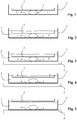
- FIG. 1 illustrates the situation in a first step for carrying out an exemplary embodiment of the method according to the invention.
- a tissue sample 1 is held in a desired orientation in a container 2 by means of a holding element 3 which presses the tissue sample 1 against a base 4 of the container 2.
- the holding element 3 can, for example, as be formed spring-loaded screen. The fact that the tissue sample 1 is clamped between the holding element 3 and the base 4 ensures that the tissue sample 1 maintains its target orientation.
- the base 4 of the container 2 is cooled by bringing the base 4 into contact with a cooling element 6, which is shown in FIG Figure 3 is illustrated.
- the cooling element 6 is designed as a cooling plate on which the container 2 is placed.
- the holding element 3 always holds the tissue sample 1 in its position and target orientation.
- the layer of the embedding medium 5 in which the holding element 3 is located has a temperature in the range of 54 degrees Celsius to 64 degrees Celsius, in particular 60 degrees Celsius
- a separating movement is started through which the tissue sample 1 and the holding element 3 are separated separate what is in Figure 4 is shown.
- the embedding medium 5 has already cooled sufficiently in the area of the base and thereby hardened in order to hold the tissue sample 1 in its position and orientation, so that holding by means of the holding element 3 has become unnecessary.
- the separation movement is completed within a predetermined time window of 17 to 20 seconds.
- the separation movement should take place and be completed within a second time period t2 immediately following the first time period t 1 .
- Particularly good results are achieved if the second time period t2 is 17 to 20 seconds long.
Description
Die Erfindung betrifft ein Verfahren zum Einbetten einer Gewebeprobe in ein Einbettmedium.The invention relates to a method for embedding a tissue sample in an embedding medium.
Die Erfindung betrifft außerdem einen Automaten zum Ausführen eines solchen Verfahrens, sowie die Verwendung einer Gewebekassette, die einen Behälter mit einer Basis und ein Halteelement zum Halten wenigstens einer Gewebeprobe an der Basis aufweist, bei der Ausführung eines solchen Verfahrens.The invention also relates to an automatic machine for carrying out such a method, as well as the use of a tissue cassette, which has a container with a base and a holding element for holding at least one tissue sample on the base, when carrying out such a method.
Es ist bekannt, wie eine biologische Gewebeprobe für eine histologische Untersuchung zu verarbeiten ist. Zunächst erfolgen der Zuschnitt der Gewebeprobe und das Einbringen in eine Kassette. Anschließend wird die Probe durch eine Mehrzahl von chemischen Behandlungen für eine mikroskopische Untersuchung präpariert. Hierbei wird die Probe zunächst mit einem Fixiermedium fixiert, das in der Probe befindliche Wasser entzogen und ggf. weitere Bearbeitungsschritte vollzogen. Am Ende dieses mehrstufigen Prozesses steht das Infiltrieren eines Infiltrationsmediums, zumeist Paraffin, in die Probe.It is known how to process a biological tissue sample for histological examination. First, the tissue sample is cut to size and placed in a cassette. The sample is then prepared for microscopic examination through a variety of chemical treatments. Here, the sample is first fixed with a fixing medium, the water in the sample is removed and, if necessary, further processing steps are carried out. At the end of this multi-stage process, an infiltration medium, mostly paraffin, is infiltrated into the sample.
Danach wird die Probe, zumeist von Hand, in ein Einbettmedium, beispielsweise Paraffin, eingebettet. Hierzu wird die Probe in eine Ausgießform, die auch Mold genannt wird, eingelegt und die Ausgießform mit dem zunächst flüssigen Einbettmedium aufgefüllt. Anschließend härtet das Einbettmedium aus. Im Ergebnis entsteht ein Einbettblock, in dem die Probe von dem Einbettmedium umschlossen und ortsfest fixiert ist.The sample is then embedded, mostly by hand, in an embedding medium such as paraffin. For this purpose, the sample is placed in a pouring mold, which is also called a mold, and the pouring mold is filled with the initially liquid embedding medium. The embedding medium then hardens. The result is an embedding block in which the sample is enclosed by the embedding medium and fixed in place.
Nach dem Aushärten des Einbettmediums kann der Einbettblock, der die Probe beinhaltet, mit dem Mikrotom in einzelne dünne Probenschnitte geschnitten werden, die in einem nächsten Schritt gefärbt und dann mit einem Mikroskop untersucht werden können. Hierzu ist es wichtig, dass die Gewebeprobe innerhalb des Einbettblocks eine bestimmte Ausrichtung aufweist. Dies insbesondere um ein ordnungsgemäßes Schneiden zu gewährleisten und um zu gewährleisten, dass die Gewebeprobe entlang der bei der mikroskopischen Untersuchung interessierenden Probenschichten geschnitten werden kann.After the embedding medium has hardened, the embedding block containing the sample can be cut with the microtome into individual thin sample sections, which can then be colored in a next step and then examined with a microscope. For this it is important that the Tissue sample has a specific orientation within the embedding block. This in particular to ensure proper cutting and to ensure that the tissue sample can be cut along the sample layers that are of interest in the microscopic examination.
Um den Prozesses des Einbettens automatisieren zu können ist es erforderlich, dass die Gewebeprobe während des Einbettvorganges ihre Sollausrichtung relativ zu dem Ausgießgefäß beibehält. Verwendet man ein Halteelement, das die Gewebeprobe in ihrer Ausrichtung hält, besteht das Problem, dass das Halteelement zwangsläufig zusammen mit der Gewebeprobe eingebettet wird und das spätere Erzeugen von Probenschnitten behindert und/oder sogar die Mikrotomklinge beschädigt.In order to be able to automate the embedding process, it is necessary for the tissue sample to maintain its target orientation relative to the pouring vessel during the embedding process. If a holding element is used that holds the tissue sample in its alignment, there is the problem that the holding element is inevitably embedded together with the tissue sample and hinders the subsequent generation of sample sections and / or even damages the microtome blade.
Aus
Anstelle eines schneidbaren Trägers kann auch eine spezielle Gewebekassette verwendet werden, wie sie aus
Konkret ist aus
Allerdings ist die Verwendung einer solchen Gewebekassette in der Praxis nicht unproblematisch, weil eine ganze Reihe von störenden Phänomenen auftreten können, die sogar dazu führen können, dass die Gewebeprobe unbrauchbar wird. Beispielsweise kann es dazu kommen, dass sich die Gewebeprobe ungewollt beim Rückziehvorgang bewegt oder beschädigt wird oder gar dazu, dass sich die Gewebeeingriffsfläche gar nicht oder nicht ausreichend weit zurückziehen lässt.However, the use of such a tissue cassette is not without problems in practice because a whole series of disruptive phenomena can occur which can even lead to the tissue sample becoming unusable. For example, it can happen that the tissue sample is unintentionally moved or damaged during the retraction process, or even that the tissue engagement surface cannot be retracted at all or cannot be retracted sufficiently.
Es ist daher die Aufgabe der vorliegenden Erfindung, ein Verfahren anzugeben, das automatisiert ausführbar ist und ein zuverlässiges Erzeugen eines Einbettblocks ermöglicht, in dem eine Gewebeprobe eine vordefinierte Ausrichtung aufweist.It is therefore the object of the present invention to provide a method specify that can be carried out automatically and that enables an embedding block to be reliably generated in which a tissue sample has a predefined orientation.
Die Aufgabe wird durch ein Verfahren gelöst, das durch folgende Schritte gekennzeichnet ist:
- a. Haltern der Gewebeprobe in einer Sollausrichtung in einem Behälter mittels eines Haltelements, das die Gewebeprobe gegen eine Basis des Behälters drückt,
- b. Einfüllen eines flüssigen Einbettmediums, nämlich Paraffin, das einen Tropfpunkt im Bereich von 50 Grad Celsius bis 60 Grad Celsius hat und das eine Temperatur aufweist, die 4 Grad Celsius bis 7 Grad Celsius über dem Tropfpunkt des Einbettmediums liegt, in den Behälter,
- c. Abkühlen der Basis des Behälters) dadurch, dass der Behälter (2) mit einem Kühlelement in wärmeleitenden Kontakt gebracht wird,
- d. Ausführen einer Trennbewegung, durch die sich die Gewebeprobe und das Haltelement voneinander entfernen, wobei
- i. die Trennbewegung entweder unmittelbar nach Ablauf einer Zeitspanne (t1) im Bereich von 1 Sekunde bis 4 Sekunden nach dem Beginn des Abkühlens automatisch gestartet wird, oder stattdessen die Temperatur des Einbettmediums oder des Behälters oder des Halteelements mit einem Temperatursensor gemessen wird und die Trennbewegung automatisch ausgelöst wird, sobald die gemessene Temperatur eine vorgegebene oder vorgebbare Auslösetemperatur erreicht, und wobei
- ii. die Schichten des Einbettmediums, durch die sich das Halteelement während der Trennbewegung bewegt, während der Trennbewegung noch flüssig sind und Temperaturen im Bereich von 54 Grad Celsius bis 64 Grad Celsius, insbesondere von 60 Grad Celsius, aufweisen, und/oder wobei die jeweils unmittelbar an das Halteelement angrenzenden Anteile des Einbettmediums während der Trennbewegung noch flüssig sind und eine Temperatur im Bereich von 54 Grad Celsius bis 64 Grad Celsius, insbesondere von 60 Grad Celsius, aufweisen.
- a. Holding the tissue sample in a desired orientation in a container by means of a holding element which presses the tissue sample against a base of the container,
- b. Filling a liquid embedding medium, namely paraffin, which has a dropping point in the range of 50 degrees Celsius to 60 degrees Celsius and a temperature that is 4 degrees Celsius to 7 degrees Celsius above the dropping point of the embedding medium, into the container,
- c. Cooling the base of the container) in that the container (2) is brought into thermally conductive contact with a cooling element,
- d. Execution of a separating movement by which the tissue sample and the holding element move away from one another, wherein
- i. the separating movement is either started automatically immediately after a period of time (t 1 ) in the range from 1 second to 4 seconds after the start of cooling, or instead the temperature of the embedding medium or the container or the holding element is measured with a temperature sensor and the separating movement is automatic is triggered as soon as the measured temperature reaches a reached predetermined or predefinable trigger temperature, and where
- ii. the layers of the embedding medium through which the holding element moves during the separating movement, are still liquid during the separating movement and have temperatures in the range from 54 degrees Celsius to 64 degrees Celsius, in particular 60 degrees Celsius, and / or which are each immediately on The parts of the embedding medium adjacent to the holding element are still liquid during the separating movement and have a temperature in the range from 54 degrees Celsius to 64 degrees Celsius, in particular 60 degrees Celsius.
Die Aufgabe wird auch durch einen Automaten gemäß Anspruch 10 gelöst.The object is also achieved by a machine according to claim 10.
Die Erfindung hat den ganz besonderen Vorteil, dass einerseits stets zuverlässig ein Halten der Gewebeprobe in ihrer Ausrichtung relativ zu dem Behälter sichergestellt ist und gleichzeitig andererseits gewährleistet ist, dass das Halteelement entfernt werden kann, ohne im Einbettmedium stecken zu bleiben und ohne die Gewebeprobe in ihrer Lage zu verändern oder gar zu beschädigen.The invention has the particular advantage that, on the one hand, the tissue sample is always reliably held in its alignment relative to the container and, on the other hand, it is ensured that the holding element can be removed without getting stuck in the embedding medium and without the tissue sample in it To change the position or even to damage it.
In erfindungsgemäßer Weise wurde erkannt, dass die an die gekühlte Basis angrenzenden Anteile des Einbettmediums bereits ausreichend ausgehärtet sind, um die Gewebeprobe in ihrer Position und Ausrichtung zu halten, wenn die Temperatur des Einbettmediums am Ort des Halteelements noch im Bereich von 54 Grad Celsius bis 64 Grad Celsius, insbesondere bei 60 Grad Celsius liegen, so dass das Halteelement von der Gewebeprobe entfernt werden kann. In diesem Temperaturbereich ist das Einbettmedium noch ausreichend flüssig, um das Halteelement störungsfrei und insbesondere ohne die Gewebeprobe in ihrer Position oder Ausrichtung zu beeinflussen oder zu beschädigen oder die Qualität des Aushärtungsprozesses negativ zu beeinflussen, entfernen zu können. Insbesondere kann vorteilhaft vorgesehen sein, dass das Einbettmedium während des Ausführens der Trennbewegung eine mittlere Temperatur im Bereich von 54 Grad Celsius bis 64 Grad Celsius, insbesondere von 60 Grad Celsius, aufweist.According to the invention, it was recognized that the parts of the embedding medium adjoining the cooled base are already sufficiently hardened to hold the tissue sample in its position and orientation when the temperature of the embedding medium at the location of the holding element is still in the range of 54 degrees Celsius to 64 degrees Celsius Degrees Celsius, in particular 60 degrees Celsius, so that the holding element can be removed from the tissue sample. In this temperature range, the embedding medium is still sufficiently liquid to allow the holding element to be in position without interference and, in particular, without the tissue sample or affect or damage alignment or negatively affect the quality of the curing process, remove. In particular, it can advantageously be provided that the embedding medium has an average temperature in the range from 54 degrees Celsius to 64 degrees Celsius, in particular 60 degrees Celsius, while the separating movement is being carried out.
Für die Ausführung der einzelnen Verfahrensschritte bei oben genannten Temperaturen ist insbesondere bei der Verwendung von Paraffin als Einbettmedium vorgesehen, wobei das Paraffin einen Tropfpunkt im Bereich von 50 Grad Celsius bis 60 Grad Celsius hat. Bei Verwendung von Einbettmedien mit anderen Tropfpunkten können die Temperaturen, bei denen die einzelnen Verfahrensschritte ausgeführt werden, entsprechend angepasst werden.For the execution of the individual process steps at the above-mentioned temperatures, provision is made in particular when using paraffin as the embedding medium, the paraffin having a dropping point in the range from 50 degrees Celsius to 60 degrees Celsius. When using embedding media with other dropping points, the temperatures at which the individual process steps are carried out can be adjusted accordingly.
Insbesondere kann vorteilhaft vorgesehen sein, dass die Trennbewegung, insbesondere automatisch, ausgelöst wird, sobald die unmittelbar an die Basis angrenzende Schicht des Einbettmediums eine Temperatur von 52 Grad Celsius erreicht hat. In erfindungsgemäßer Weise wurde erkannt, dass dies dann der Fall ist, wenn die Temperatur des Einbettmediums am Ort des Halteelements im Bereich von 54 Grad Celsius bis 64 Grad Celsius, insbesondere bei 60 Grad Celsius liegt.In particular, it can advantageously be provided that the separating movement is triggered, in particular automatically, as soon as the layer of the embedding medium immediately adjacent to the base has reached a temperature of 52 degrees Celsius. According to the invention, it was recognized that this is the case when the temperature of the embedding medium at the location of the holding element is in the range from 54 degrees Celsius to 64 degrees Celsius, in particular 60 degrees Celsius.
Nach dem vollständigen Ausführen der Trennbewegung lässt man das Einbettmedium weiter erkalten, bis es vollständig ausgehärtet ist und der entstandene Einbettblock aus dem Behälter entnommen werden kann.After the separation movement has been completed, the embedding medium is allowed to cool further until it has hardened completely and the embedding block that has been created can be removed from the container.
Bei einer besonders vorteilhaften Ausführung wird das Halteelement nicht vollständig aus dem Einbettmedium entfernt. Vielmehr kann die Trennbewegung vorteilhaft enden, solange sich das Haltelement noch innerhalb des Einbettmediums befindet. Auf diese Weise wird das Halteelement mit eingebettet. Eine solche Ausführung hat den ganz besonderen Vorteil, dass das Halteelement dem durch Erkalten des Einbettmediums entstehenden Einbettblock eine zusätzliche mechanische Stabilität verleiht. Auf diese Weise wird vorteilhaft verhindert, dass sich der Einbettblock beim späteren Einspannen und/oder beim Schneiden mit einem Mikrotom ungewollt verformt. Auch ist es möglich, mit dem Haltelement verbundene Vorsprünge, die aus dem Einbettblock ragen, zum Einspannen zu verwenden. Dadurch, dass das Halteelement mittels der Trennbewegung von der Gewebeprobe entfernt wurde, ist jedoch gleichzeitig vorteilhaft sichergestellt, dass bei der Herstellung von Gewebeschnitten nicht in das stabilisierende Haltelement hinein geschnitten werden muss.In a particularly advantageous embodiment, the holding element is not completely removed from the embedding medium. Rather, the separating movement can advantageously end as long as the holding element is still located within the embedding medium. In this way, the holding element is also embedded. Such an embodiment has the very special advantage that the holding element corresponds to the cooling of the The resulting embedding block gives additional mechanical stability. In this way, it is advantageously prevented that the embedding block is unintentionally deformed during later clamping and / or when cutting with a microtome. It is also possible to use projections connected to the holding element, which protrude from the embedding block, for clamping. The fact that the holding element was removed from the tissue sample by means of the separating movement, however, at the same time advantageously ensures that there is no need to cut into the stabilizing holding element when producing tissue incisions.
Die Erfindung ist nicht darauf beschränkt, jeweils eine einzige Gewebeprobe einzubetten. Vielmehr ist es auch möglich, gleichzeitig mehrere Gewebeproben in demselben Behälter auf die beschriebene Weise einzubetten. Soweit im Rahmen dieser Anmeldung davon die Rede ist, dass eine Gewebeprobe eingebettet wird, dient dies lediglich der einfacheren Erläuterung der Erfindung, ohne dass damit eine Einschränkung einher gehen soll.The invention is not limited to embedding a single tissue sample at a time. Rather, it is also possible to simultaneously embed several tissue samples in the same container in the manner described. Insofar as it is mentioned in the context of this application that a tissue sample is embedded, this only serves to simplify the explanation of the invention, without this being intended to be associated with a restriction.
Das Einbettmedium kann beispielsweise Paraffin sein oder, insbesondere überwiegend, Paraffin beinhalten.The embedding medium can be, for example, paraffin or, in particular predominantly, contain paraffin.
Bei einer ganz besonders vorteilhaften Ausführung des Verfahrens hat das Einbettmedium, bei dem es sich um Paraffin mit einem Tropfpunkt im Bereich von 50 Grad Celsius bis 60 Grad Celsius, handelt, beim Einfüllen eine Temperatur über 64 Grad Celsius. Auf diese Weise ist sichergestellt, dass das Einbettmedium den gesamten zur Verfügung stehenden Raum innerhalb des Behälters ausfüllt, bevor es erkaltet. Besonders vorteilhaft ist eine Einfülltemperatur im Bereich von 65 bis 67 Grad Celsius, insbesondere eine Temperatur von 66 Grad Celsius. Bei einer solchen Temperatur ist sichergestellt, dass die Gewebeprobe zuverlässig und allseitig mit dem Einbettmedium umschlossen wird. Darüber hinaus ist die Zeitdauer, die zum Aushärten des Einbettmediums im Bereich der Basis und anschließend zum vollständigen Aushärten in den übrigen Bereichen erforderlich ist, besonders kurz. Auf diese Weise werden hohe Durchsatzraten erreicht, so dass pro Zeiteinheit, beispielsweise von einem Automaten, besonders viele Gewebeproben eingebettet werden können.In a particularly advantageous embodiment of the method, the embedding medium, which is paraffin with a dropping point in the range from 50 degrees Celsius to 60 degrees Celsius, has a temperature of over 64 degrees Celsius when it is filled. In this way it is ensured that the embedding medium fills the entire available space within the container before it cools down. A filling temperature in the range from 65 to 67 degrees Celsius, in particular a temperature of 66 degrees Celsius, is particularly advantageous. At such a temperature it is ensured that the tissue sample is reliably surrounded on all sides with the embedding medium. In addition, the time it takes for the embedding medium to cure in the area of the base and subsequently is required for complete curing in the remaining areas, particularly briefly. In this way, high throughput rates are achieved, so that a particularly large number of tissue samples can be embedded per unit of time, for example by a machine.
Der Tropfpunkt kann sich bei unterschiedlichartigen Einbettmedien unterscheiden. Es gibt beispielsweise Einbettmedien, die einen Tropfpunkt im Bereich von 52 Grad Celsius bis 58 Grad Celsius aufweisen, was beispielsweise in
Erfindungsgemäß ist vorgesehen, dass das Einbettmedium beim Einfüllen eine Temperatur aufweist, die 4 Grad Celsius bis 7 Grad Celsius über dem Tropfpunkt des Einbettmediums liegt. Insbesondere kann vorteilhaft vorgesehen sein, dass das Einbettmedium beim Einfüllen eine Temperatur aufweist, die 5 bis 7 Grad Celsius über dem Tropfpunkt des Einbettmediums liegt und/oder die 6 Grad Celsius über dem Tropfpunkt des Einbettmediums liegt. Beispielsweise ein Einbettmedium, das einen Tropfpunkt von beispielsweise 55 Grad Celsius aufweist, kann vorteilhaft insbesondere bei einer Temperatur 61 Grad Celsius eingefüllt werden.According to the invention, it is provided that the embedding medium has a temperature during filling which is 4 degrees Celsius to 7 degrees Celsius above the dropping point of the embedding medium. In particular, it can advantageously be provided that the embedding medium has a temperature during filling which is 5 to 7 degrees Celsius above the dropping point of the embedding medium and / or which is 6 degrees Celsius above the dropping point of the embedding medium. For example, an embedding medium that has a dropping point of 55 degrees Celsius, for example, can advantageously be filled in, in particular at a temperature of 61 degrees Celsius.
Nachfolgend wird erläutert, wie und insbesondere wann die Trennbewegung eingeleitet wird.The following explains how and, in particular, when the separating movement is initiated.
Beispielsweise kann, wie oben erwähnt, vorgesehen sein, dass die Trennbewegung bei Erreichen einer vorgegebenen oder vorgebbaren Auslösetemperatur des Einbettmediums oder des Behälters oder des Haltelements, insbesondere automatisch, ausgelöst wird. Hierzu wird die Temperatur mit einem Temperatursensor direkt gemessen. Alternativ ist es auch möglich, über einen anderen Parameter auf die Temperatur rückzuschließen, um so festzustellen, ob die Auslösetemperatur erreicht ist. Insbesondere ist es möglich, über die Zeitdauer seit dem Beginn des Kühlvorganges an der Basis auf die Temperatur des Einbettmediums oder des Behälters oder des Haltelements zu schließen. Insbesondere kann hier zuvor der Durchführung des Verfahrens eine kann Kalibrationsmessung durchgeführt worden sein, um festzustellen, nach welcher Zeitspanne die Auslösetemperatur vorliegt. Die Dauer der Zeitspanne kann insbesondere von der Art und Größe des Behälters und von der Art des Einbettmediums abhängen.For example, as mentioned above, it can be provided that the separating movement is triggered, in particular automatically, when a specified or specifiable trigger temperature of the embedding medium or the container or the holding element is reached. For this purpose, the temperature is measured directly with a temperature sensor. Alternatively, it is also possible to draw conclusions about the temperature using another parameter in order to determine whether the trigger temperature has been reached. In particular, it is possible to infer the temperature of the embedding medium or of the container or of the holding element over the period of time since the start of the cooling process at the base. In particular, here a calibration measurement may have been carried out prior to carrying out the method in order to determine the time span after which the triggering temperature is present. The duration of the period of time can depend in particular on the type and size of the container and on the type of embedding medium.
Das Halteelement kann vorteilhaft beispielsweise als Sieb ausgebildet sein. Ein derart ausgebildetes Halteelement hat den Vorteil, dass das Einbettmedium während der Trennbewegung durch die Sieböffnungen strömen kann. Auf diese Weise wird vorteilhaft erreicht, dass Turbulenzen im Einbettmedium, die die Ausrichtung der Gewebeprobe negativ beeinflussen könnten, während der Trennbewegung weitgehend vermieden sind. Außerdem hat eine derartige Ausbildung den weiteren Vorteil, dass der Trennbewegung weniger Widerstand entgegengesetzt wird und die Gefahr des Steckenbleibens des Halteelements verringert ist.The holding element can advantageously be designed as a sieve, for example. A holding element designed in this way has the advantage that the embedding medium can flow through the sieve openings during the separating movement. In this way it is advantageously achieved that turbulence in the embedding medium, which could negatively affect the alignment of the tissue sample, is largely avoided during the separating movement. In addition, such a design has the further advantage that there is less resistance to the separating movement and the risk of the holding element getting stuck is reduced.
Das Halteelement kann zum Ausführen der Trennbewegung auf unterschiedlichste Art bewegt werden. Beispielsweise ist es möglich, mittels eines Magneten eine Kraft auf das Halteelemente auszuüben. Hierzu kann das Halteelement wenigstens teilweise aus einem magnetischen Material bestehen. Es ist auch möglich, das Halteelement mittels eines Greifers horizontal und/oder vertikal zu bewegen. Der Greifer kann beispielsweise als Haken ausgebildet sein, der sich zum Ausführen der Trennbewegung an dem Halteelement einhakt. Wie bereits erwähnt, kann auch vorgesehen sein, dass das Halteelement zum Ausführen der Trennbewegung mittels eines Haltemechanismus bewegt wird, der ein Formgedächtnisbauteil, beispielsweise auf der Basis von Memory-Polymeren, aufweist.The holding element can be moved in the most varied of ways to perform the separating movement. For example, it is possible to exert a force on the holding element by means of a magnet. For this purpose, the holding element can at least partially consist of a magnetic material. It is also possible to move the holding element horizontally and / or vertically by means of a gripper. The gripper can be designed, for example, as a hook which hooks onto the holding element in order to carry out the separating movement. As already mentioned, it can also be provided that the holding element is moved by means of a holding mechanism in order to carry out the separating movement, which has a shape memory component, for example based on memory polymers.
Es ist erfindungsgemäß vorgesehen, dass der Zeitpunkt des Beginns des Abkühlens als Zeitbasis herangezogen wird und die Trennbewegung unmittelbar nach Ablauf einer vorgegebenen oder vorgebbaren Zeitspanne nach dem Beginn des Abkühlens beginnt, und/oder dass die Trennbewegung unmittelbar nach Ablauf einer vorgegebenen oder vorgebbaren Zeitspanne nach dem Beginn des Abkühlens automatisch gestartet wird. Erfindungsgemäß ist vorgesehen, dass die Zeitspanne zwischen dem Beginn des Abkühlens und dem Beginn der Trennbewegung im Bereich von 1 Sekunde bis 4 Sekunden, insbesondere im Bereich von 2 Sekunden bis 3 Sekunden liegt.It is provided according to the invention that the point in time at which cooling begins is used as the time base and the separating movement begins immediately after a predetermined or predeterminable period of time after the beginning of cooling, and / or that the Separation movement is automatically started immediately after a predetermined or predeterminable period of time after the start of cooling. According to the invention, it is provided that the time span between the start of cooling and the start of the separating movement is in the range from 1 second to 4 seconds, in particular in the range from 2 seconds to 3 seconds.
Insbesondere um zu gewährleisten, dass das Halteelement nicht vor Abschluss der Trennbewegung im erkaltenden und zunehmend erstarrenden Einbettmedium ungewollt gestoppt wird, sollte die Trennbewegung innerhalb eines vorgegebenen oder vorgebbaren Zeitfensters ablaufen und/oder eine vorgegebene oder vorgebbare Zeitspanne andauern. Besonders gute Ergebnisse werden erzielt, wenn das Zeitfenster 17 bis 20 Sekunden lang ist und/oder dass die Zeitspanne andauert 17 bis 20 Sekunden andauert.In particular, to ensure that the holding element is not unintentionally stopped before the end of the separating movement in the cooling and increasingly solidifying embedding medium, the separating movement should take place within a predefined or predefinable time window and / or last a predefined or predefinable time period. Particularly good results are achieved if the time window is 17 to 20 seconds long and / or if the time span lasts 17 to 20 seconds.
Das Abkühlen der Basis des Behälters wird dadurch bewirkt, dass der Behälter mit einem Kühlelement in wärmeleitenden Kontakt gebracht wird. Bei dem Kühlelement kann es sich beispielsweise um eine Kühlplatte handeln, auf die der Behälter gestellt wird.The base of the container is cooled down by bringing the container into thermally conductive contact with a cooling element. The cooling element can be, for example, a cooling plate on which the container is placed.
Es ist zur Durchführung des Verfahrens beispielsweise möglich, zunächst das Einbettmedium in den Behälter einzufüllen und anschließend die Basis des Behälters, beispielsweise durch In-Kontakt-Bringen mit einer Kühlplatte, zu kühlen. Bei einer solchen Ausführung kann der Moment des In-Kontakt-Bringens als Startzeitpunkt für die Zeitspanne, nach deren Ablauf die Trennbewegung gestartet wird, herangezogen werden. Alternativ ist es auch möglich, zunächst den Behälter an der Basis, beispielsweise durch In-Kontakt-Bringen mit einer Kühlplatte, zu kühlen und anschließend das Einbettmedium einzufüllen. In diesem Fall kann der Zeitpunkt des Einfüllens, insbesondere der Zeitpunkt der Beendigung des Einfüllvorganges, als Startzeitpunkt für Zeitspanne, nach deren Ablauf die Trennbewegung gestartet wird, herangezogen werden.To carry out the method, it is possible, for example, to first fill the embedding medium into the container and then to cool the base of the container, for example by bringing it into contact with a cooling plate. In such an embodiment, the moment of bringing into contact can be used as the starting time for the time span after which the separating movement is started. Alternatively, it is also possible to first cool the container at the base, for example by bringing it into contact with a cooling plate, and then to fill in the embedding medium. In this case, the point in time of filling, in particular the point in time at which the filling process is ended, can be used as the starting point in time for the time span after which the separating movement is started.
Bei einer ganz besonders vorteilhaften Ausführung wird der Behälter ausschließlich an der Basis gekühlt. Eine solche Ausführung hat den ganz besonderen Vorteil, dass Spannungsrisse innerhalb des erkalteten Einbettmediums wirksam vermieden werden.In a particularly advantageous embodiment, the container is cooled only at the base. Such a design has the particular advantage that stress cracks within the cooled embedding medium are effectively avoided.
Wie bereits erwähnt, kann das erfindungsgemäße Verfahren insbesondere bei einer automatisierten Verarbeitung von Gewebeproben zum Einsatz kommen. Hierbei ist es insbesondere möglich, eine Vielzahl von Gewebeproben, die in einer Vielzahl von Behältern, in denen die Gewebeproben in ihrer jeweiligen Zielausrichtung gehaltert sind, gleichzeitig einzubetten. Hierbei können beispielsweise jeweils mehrere Behälter in jeweils einer gemeinsamen Halterung, beispielsweise matrixartig und koplanar in einer Ebene, gehaltert sein. Ein solcher Halter, kann beispielsweise leicht auf einer Kühlplatte abgelegt werden, um gleichzeitig die mehreren Behälter jeweils an ihrer Basis zu kühlen. Es ist jedoch beispielsweise auch möglich, einen Halter zu verwenden, bei dem die Behälter in Stapelanordnung angeordnet sind. Bei einer solchen Ausführung könnten beispielsweise mehrere Kühlfinger vorgesehen sein, die in die Zwischenräume zwischen den Behältern greifen, um die einzelnen Behälter jeweils von unten an ihrer Basis zu kühlen. Die Verwendung einer Halterung für mehrere Behälter hat den Vorteil, dass ein Automat durch Handhaben der gemeinsamen Halterung gleichzeitig mehrere Behälter transportieren, mit einem Einbettmedium befüllen und abkühlen kann, was die Durchsatzrate erhöht.As already mentioned, the method according to the invention can be used in particular for the automated processing of tissue samples. In particular, it is possible here to simultaneously embed a large number of tissue samples in a large number of containers in which the tissue samples are held in their respective target orientation. In this case, for example, a plurality of containers can each be held in a common holder, for example in a matrix-like and coplanar manner in one plane. Such a holder can, for example, easily be placed on a cooling plate in order to simultaneously cool the several containers in each case at their base. However, it is also possible, for example, to use a holder in which the containers are arranged in a stack. In such an embodiment, for example, several cold fingers could be provided which reach into the spaces between the containers in order to cool the individual containers from below at their base. The use of a holder for several containers has the advantage that an automatic machine can simultaneously transport several containers by handling the common holder, fill them with an embedding medium and cool them, which increases the throughput rate.
Das erfindungsgemäße Verfahren kann insbesondere auch Bestandteil eines übergeordneten Verfahrens zum Verarbeiten einer Gewebeprobe oder mehrerer Gewebeproben sein, bei dem außer einem Einbetten, vorausgehend oder nachfolgend, noch weitere Prozessschritte ausgeführt werden. Bei den weiteren Prozessschritten kann es sich insbesondere darum handeln, die Gewebeprobe vor einem Einbetten mit wenigstens einem Fixiermittel zu fixieren und/oder ein Infiltrationsmedium, insbesondere Paraffin, in die Gewebeprobe zu infiltrieren. Hierbei kann insbesondere vorgesehen sein, dass auch die weiteren Prozessschritte durchgeführt werden, nachdem die Gewebeprobe in ihrer Zielausrichtung in dem Behälter angeordnet wurde. Die Gewebeprobe verbleibt insoweit während des Einbettens und während wenigstens eines vorausgehenden weiteren Prozessschritts in demselben Behälter, bis sie vollständig eingebettet ist.The method according to the invention can in particular also be part of a higher-level method for processing a tissue sample or a plurality of tissue samples, in which, in addition to embedding, further process steps are carried out beforehand or subsequently. The further process steps can in particular involve fixing the tissue sample with at least one fixing agent before embedding and / or an infiltration medium, especially paraffin, to infiltrate the tissue sample. In particular, it can be provided here that the further process steps are also carried out after the tissue sample has been arranged in its target orientation in the container. The tissue sample remains in the same container during the embedding and during at least one preceding further process step until it is completely embedded.
Von besonderem Vorteil ist die Verwendung einer Gewebekassette, die einen Behälter mit einer Basis und ein Halteelement zum Halten wenigstens einer Gewebeprobe an der Basis aufweist, für die Ausführung des erfindungsgemäßen Verfahrens.The use of a tissue cassette, which has a container with a base and a holding element for holding at least one tissue sample on the base, is particularly advantageous for carrying out the method according to the invention.
In der Zeichnung ist der Erfindungsgegenstand beispielhaft und schematisch dargestellt und wird anhand der Figuren nachfolgend beschrieben, wobei gleiche oder gleich wirkende Elemente zumeist mit denselben Bezugszeichen versehen sind. Dabei zeigen:
- Fig. 1
bis 5 - eine Illustration der Schritte gemäß einem Ausführungsbeispiel des erfindungsgemäßen Verfahrens, und
- Fig. 6
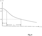
- eine Illustration des zeitlichen Temperaturverlaufs der Temperatur eines in einen Behälter eingefüllten Einbettmediums und eine Illustration der relevanten Zeitspannen bei der Durchführung eines Ausführungsbeispiels des erfindungsgemäßen Verfahrens.
- Figs. 1 to 5
- an illustration of the steps according to an embodiment of the method according to the invention, and
- Fig. 6
- an illustration of the temperature profile over time of an embedding medium filled into a container and an illustration of the relevant time periods when performing an exemplary embodiment of the method according to the invention.
In einem nächsten Schritt wird ein flüssiges Einbettmedium 5, das insbesondere Paraffin sein kann und das eine Temperatur über 64 Grad Celsius, insbesondere im Bereich von 65 Grad Celsius bis 67 Grad Celsius oder eine Temperatur von 66 Grad Celsius, aufweist, in den Behälter eingefüllt, was in
In einem nächsten Schritt erfolgt ein Abkühlen der Basis 4 des Behälters 2, durch ein In-Kontakt-Bringen der Basis 4 mit einem Kühlelement 6, was in
Sobald die Schicht des Einbettmediums 5, in der sich das Halteelement 3 befindet eine Temperatur im Bereich von 54 Grad Celsius bis 64 Grad Celsius, insbesondere von 60 Grad Celsius, aufweist, wird eine Trennbewegung gestartet, durch die sich die Gewebeprobe 1 und das Haltelement 3 voneinander entfernen, was in
Anschließend kann das Einbettmedium 5 weiter erkalten bis es vollständig ausgehärtet ist und der entstandene Einbettblock samt der eingebetteten Gewebeprobe 1 aus dem Behälter 2 entnommen werden kann.The embedding
Die Trennbewegung beginnt bei diesem Ausführungsbeispiel unmittelbar nach Ablauf einer ersten Zeitspanne t1 nach dem Beginn des Abkühlens (t = 0). Besonders gute Ergebnisse werden erzielt, wenn die erste Zeitspanne t1 im Bereich von 1 Sekunde bis 4 Sekunden oder im Bereich von 2 Sekunden bis 3 Sekunden liegt.In this exemplary embodiment, the separating movement begins immediately after a first period of time t 1 has elapsed after the start of cooling (t = 0). Particularly good results are achieved when the first time period t 1 is in the range from 1 second to 4 seconds or in the range from 2 seconds to 3 seconds.
Insbesondere um zu gewährleisten, dass das Halteelement 3 nicht vor Abschluss der Trennbewegung im erkaltenden und zunehmend erstarrenden Einbettmedium 5 ungewollt festgehalten wird, sollte die Trennbewegung innerhalb einer sich unmittelbar an die erste Zeitspanne t1 anschließenden zweiten Zeitspanne t2 stattfinden und abgeschlossen sein. Besonders gute Ergebnisse werden erzielt, wenn die zweite Zeitspanne t2 17 bis 20 Sekunden lang ist.In particular, to ensure that the holding
- 11
- GewebeprobeTissue sample
- 22
- Behältercontainer
- 33
- HalteelementRetaining element
- 44th
- BasisBase
- 55
- EinbettmediumEmbedding medium
- 66th
- KühlelementCooling element
- t1 t 1
- erste Zeitspannefirst time span
- t2 t 2
- zweite Zeitspannesecond time span
Claims (9)
- Method of embedding a tissue sample (1) into an embedding medium (5), characterized by the following steps:a. holding the tissue sample (1) in a target direction in a vessel (2) by means of a holding element (3) that presses the tissue sample (1) against a base (4) of the vessel (2),b. introducing a liquid embedding medium (5), namely paraffin having a dropping point in the range from 50 degrees Celsius to 60 degrees Celsius and having a temperature 4 degrees Celsius to 7 degrees Celsius above the dropping point of the embedding medium (5), into the vessel (2),c. cooling the base (4) of the vessel (2) in such a way that the vessel (2) is brought into heat-conducting contact with a cooling element,d. executing a separating movement resulting in separation of the tissue sample (1) and the holding element (3) from one another, whereini. the separating movement is automatically started immediately after a timespan (t1) in the range from 1 second to 4 seconds after the commencement of the cooling has elapsed, or instead the temperature of the embedding medium (5) or of the vessel (2) or of the holding element (3) is measured with a temperature sensor and the separating movement is automatically triggered as soon as the measured temperature reaches a defined or definable trigger temperature, and whereinii. the layers of the embedding medium (5) through which the holding element (3) moves during the separating movement are still liquid during the separating movement and have temperatures in the range from 54 degrees Celsius to 64 degrees Celsius, especially of 60 degrees Celsius, and/or wherein the portions of the embedding medium (5) directly adjoining the holding element (3) in each case are still liquid during the separating movement and have a temperature in the range from 54 degrees Celsius to 64 degrees Celsius, especially of 60 degrees Celsius.
- Method according to Claim 1, characterized in that the embedding medium (5) during the execution of the separating movement has an average temperature in the range from 54 degrees Celsius to 64 degrees Celsius, especially of 60 degrees Celsius.
- Method according to either of Claims 1 and 2, characterized in that the embedding medium (5) on introduction has a temperature above 64 degrees Celsius and/or a temperature in the range from 65 to 67 degrees Celsius and/or a temperature of 66 degrees Celsius.
- Method according to any of Claims 1 to 3, characterized in thata. the separating movement proceeds within a defined or definable time window and/or lasts for a defined or definable timespan (t2), and/or in thatb. the separating movement proceeds within a defined or definable time window and/or lasts for a defined or definable timespan (t2), wherein the time window is 17 to 20 seconds long and/or in that the timespan (t2) lasts for 17 to 20 seconds.
- Method according to any of Claims 1 to 4, characterized in that the vessel (2) is cooled exclusively at the base (4).
- Method according to any of Claims 1 to 5, characterized in that the separating movement ends while the holding element is still within the embedding medium and/or in that the holding element is embedded together with the tissue sample.
- Method of processing a tissue sample (1), in which the tissue sample (1) is introduced into a vessel (2) and, while it is within the vessel (2), is fixed with at least one fixative and/or infiltrated with an infiltration medium, especially paraffin, characterized in that the tissue sample (1) remains in the vessel (2) after the fixing and/or infiltrating and is blocked by means of a method according to any of Claims 1 to 6.
- Use of a tissue cassette having a vessel (2) with a base (4) and a holding element for holding at least one tissue sample (1) on the base (4), in the execution of a method according to any of Claims 1 to 7.
- Machine for executing a method as claimed in any of Claims 1 to 7, comprisinga. a cooling element (6) for cooling the base (4) of the vessel andb. means of automated execution of the separating movement of step d of Claim 1.
Applications Claiming Priority (1)
| Application Number | Priority Date | Filing Date | Title |
|---|---|---|---|
| DE102015114893.5A DE102015114893A1 (en) | 2015-09-04 | 2015-09-04 | Method and automaton for embedding a tissue sample in an embedding medium |
Publications (2)
| Publication Number | Publication Date |
|---|---|
| EP3139150A1 EP3139150A1 (en) | 2017-03-08 |
| EP3139150B1 true EP3139150B1 (en) | 2020-10-28 |
Family
ID=56683768
Family Applications (1)
| Application Number | Title | Priority Date | Filing Date |
|---|---|---|---|
| EP16183479.1A Active EP3139150B1 (en) | 2015-09-04 | 2016-08-10 | Method and machine for embedding a tissue sample in an embedding medium |
Country Status (6)
| Country | Link |
|---|---|
| US (1) | US10481054B2 (en) |
| EP (1) | EP3139150B1 (en) |
| JP (2) | JP6952450B2 (en) |
| CN (1) | CN106501062B (en) |
| DE (1) | DE102015114893A1 (en) |
| ES (1) | ES2842029T3 (en) |
Cited By (3)
| Publication number | Priority date | Publication date | Assignee | Title |
|---|---|---|---|---|
| US11709155B2 (en) | 2017-09-18 | 2023-07-25 | Waters Technologies Corporation | Use of vapor deposition coated flow paths for improved chromatography of metal interacting analytes |
| US11709156B2 (en) | 2017-09-18 | 2023-07-25 | Waters Technologies Corporation | Use of vapor deposition coated flow paths for improved analytical analysis |
| US11918936B2 (en) | 2020-01-17 | 2024-03-05 | Waters Technologies Corporation | Performance and dynamic range for oligonucleotide bioanalysis through reduction of non specific binding |
Families Citing this family (2)
| Publication number | Priority date | Publication date | Assignee | Title |
|---|---|---|---|---|
| CN107463193B (en) * | 2017-08-30 | 2022-09-09 | 中国医科大学附属第一医院 | Low temperature tissue embedding temperature control system |
| WO2023184382A1 (en) * | 2022-03-31 | 2023-10-05 | Leica Biosystems Nussloch Gmbh | Device for pressing cassette and embedder having same |
Family Cites Families (15)
| Publication number | Priority date | Publication date | Assignee | Title |
|---|---|---|---|---|
| JP4695286B2 (en) * | 2001-04-20 | 2011-06-08 | サクラ精機株式会社 | Embedding apparatus and temperature control method thereof |
| CN101435753B (en) | 2002-09-26 | 2011-08-03 | 比欧帕斯自动化公司 | Box for keeping tissue specimen |
| US9234823B2 (en) * | 2005-09-06 | 2016-01-12 | Leica Biosystems Melbourne Pty Ltd | Method and apparatus for handling tissue samples |
| WO2008074073A1 (en) * | 2006-12-18 | 2008-06-26 | Leica Biosystems Melbourne Pty Ltd | Device and method for tissue handling and embedding |
| JP2010185673A (en) * | 2009-02-10 | 2010-08-26 | Hamamatsu Univ School Of Medicine | Tissue microarray preparation method |
| DE102009035019A1 (en) | 2009-07-28 | 2011-02-10 | Leica Biosystems Nussloch Gmbh | Histological embedding medium |
| US9067295B2 (en) | 2012-07-25 | 2015-06-30 | Applied Materials, Inc. | Monitoring retaining ring thickness and pressure control |
| GB2510466B (en) * | 2012-12-28 | 2015-05-06 | Leica Biosystems Nussloch Gmbh | Processor for processing histological samples |
| DE102013204651A1 (en) | 2013-03-15 | 2014-09-18 | Leica Biosystems Nussloch Gmbh | Tissue cassette with retractable component |
| CA2845830C (en) * | 2013-03-15 | 2020-10-27 | Leica Biosystems Nussloch Gmbh | Tissue cassette with retractable member |
| US9052256B2 (en) * | 2013-03-15 | 2015-06-09 | Leica Biosystems Nussloch Gmbh | Method for processing and embedding tissue |
| DE102013204649A1 (en) * | 2013-03-15 | 2014-09-18 | Leica Biosystems Nussloch Gmbh | Method for processing tissue samples |
| DE102013204648A1 (en) * | 2013-03-15 | 2014-09-18 | Leica Biosystems Nussloch Gmbh | Tissue cassette with preload |
| CA2845832C (en) * | 2013-03-15 | 2020-09-22 | Leica Biosystems Nussloch Gmbh | Tissue cassette with biasing element |
| DE102013225397A1 (en) * | 2013-12-10 | 2015-06-11 | Leica Biosystems Nussloch Gmbh | Embedding machine and method for embedding a histological sample |
-
2015
- 2015-09-04 DE DE102015114893.5A patent/DE102015114893A1/en not_active Ceased
-
2016
- 2016-08-10 EP EP16183479.1A patent/EP3139150B1/en active Active
- 2016-08-10 ES ES16183479T patent/ES2842029T3/en active Active
- 2016-09-01 US US15/254,211 patent/US10481054B2/en active Active
- 2016-09-01 JP JP2016170713A patent/JP6952450B2/en active Active
- 2016-09-05 CN CN201610801361.5A patent/CN106501062B/en active Active
-
2021
- 2021-07-29 JP JP2021124068A patent/JP7145298B2/en active Active
Non-Patent Citations (1)
| Title |
|---|
| ANONYMOUS: "Paraffin Processing of Tissue | Protocols Online", 12 March 2019 (2019-03-12), XP055567658, Retrieved from the Internet <URL:https://www.protocolsonline.com/histology/sample-preparation/paraffin-processing-of-tissue/> [retrieved on 20190312] * |
Cited By (3)
| Publication number | Priority date | Publication date | Assignee | Title |
|---|---|---|---|---|
| US11709155B2 (en) | 2017-09-18 | 2023-07-25 | Waters Technologies Corporation | Use of vapor deposition coated flow paths for improved chromatography of metal interacting analytes |
| US11709156B2 (en) | 2017-09-18 | 2023-07-25 | Waters Technologies Corporation | Use of vapor deposition coated flow paths for improved analytical analysis |
| US11918936B2 (en) | 2020-01-17 | 2024-03-05 | Waters Technologies Corporation | Performance and dynamic range for oligonucleotide bioanalysis through reduction of non specific binding |
Also Published As
| Publication number | Publication date |
|---|---|
| CN106501062A (en) | 2017-03-15 |
| JP7145298B2 (en) | 2022-09-30 |
| EP3139150A1 (en) | 2017-03-08 |
| US20170067804A1 (en) | 2017-03-09 |
| ES2842029T3 (en) | 2021-07-12 |
| JP2021179444A (en) | 2021-11-18 |
| CN106501062B (en) | 2020-07-14 |
| US10481054B2 (en) | 2019-11-19 |
| DE102015114893A9 (en) | 2017-04-27 |
| DE102015114893A1 (en) | 2017-03-09 |
| JP6952450B2 (en) | 2021-10-20 |
| JP2017049251A (en) | 2017-03-09 |
Similar Documents
| Publication | Publication Date | Title |
|---|---|---|
| EP3139150B1 (en) | Method and machine for embedding a tissue sample in an embedding medium | |
| EP2964419B1 (en) | Method for assessing the structural quality of three-dimensional components | |
| DE102007022014B4 (en) | A tissue embedding device and method of operating a tissue embedding device | |
| EP3349928B1 (en) | Method and apparatus for additive manufacturing | |
| DE102015219013A1 (en) | Production of a reference body during the generative production of a component | |
| DE2142801B2 (en) | Apparatus for drawing a crystalline body from a melt film | |
| DE102013225397A1 (en) | Embedding machine and method for embedding a histological sample | |
| WO2017129812A1 (en) | System and method for measuring the porosity and pore space connectivity of a rock sample | |
| DE10001136C2 (en) | Process for the production of blocks of material with multiple test samples | |
| DE102018122173A1 (en) | Method of making a block and tissue block containing a tissue sample | |
| DE102013204646B4 (en) | Device for processing histological samples | |
| EP1336834A1 (en) | Device for treating biopsy specimens and method of use thereof | |
| EP3724627A1 (en) | Microtome and method for producing thin sections from a sample by means of a microtome | |
| DE102017216654A1 (en) | Aligning and fixing a workpiece for further processing by means of an additive manufacturing process | |
| DE202011103880U1 (en) | An apparatus comprising a mold and a Super Mega tissue embedding cassette superposed thereon for dissecting and embedding a tissue specimen in a large area embedding material on the tissue specimen, and a Super Mega Tissue Embedding Cassette therefor | |
| EP3671311B1 (en) | Bracket for object holder and cover plate for receiving objects for examination using microscopy | |
| DE10049833A1 (en) | Temperature control device, in particular for a material testing device and material testing method | |
| EP4123286A1 (en) | Casting mould for biopsies and method for manufacturing a tissue block using such a casting mould | |
| DE102010060695B4 (en) | Method for marking semiconductor wafers | |
| DE102018132227A1 (en) | Process for generating a section series, process for three-dimensional reconstruction of a microscopic sample and microtome system | |
| DE112016007049T5 (en) | GÖSSLEHRE AND GOWING METHOD USING THE SAME | |
| DE10135574B4 (en) | Method and device for producing layer structures on substrates by means of liquid phase epitaxy | |
| DE102022109993A1 (en) | Method for producing individual parts of an additively manufactured body | |
| EP1291097B1 (en) | Method and device for the determination of gas permeabilty of sand cores in particular | |
| DE102021133945A1 (en) | PROCESS FOR REUSE OF MAGNETOHYDRODYNAMIC (MHD) PRINTHEADS/NOZZLES |
Legal Events
| Date | Code | Title | Description |
|---|---|---|---|
| PUAI | Public reference made under article 153(3) epc to a published international application that has entered the european phase |
Free format text: ORIGINAL CODE: 0009012 |
|
| STAA | Information on the status of an ep patent application or granted ep patent |
Free format text: STATUS: THE APPLICATION HAS BEEN PUBLISHED |
|
| AK | Designated contracting states |
Kind code of ref document: A1 Designated state(s): AL AT BE BG CH CY CZ DE DK EE ES FI FR GB GR HR HU IE IS IT LI LT LU LV MC MK MT NL NO PL PT RO RS SE SI SK SM TR |
|
| AX | Request for extension of the european patent |
Extension state: BA ME |
|
| STAA | Information on the status of an ep patent application or granted ep patent |
Free format text: STATUS: REQUEST FOR EXAMINATION WAS MADE |
|
| 17P | Request for examination filed |
Effective date: 20170619 |
|
| RBV | Designated contracting states (corrected) |
Designated state(s): AL AT BE BG CH CY CZ DE DK EE ES FI FR GB GR HR HU IE IS IT LI LT LU LV MC MK MT NL NO PL PT RO RS SE SI SK SM TR |
|
| STAA | Information on the status of an ep patent application or granted ep patent |
Free format text: STATUS: EXAMINATION IS IN PROGRESS |
|
| 17Q | First examination report despatched |
Effective date: 20180620 |
|
| GRAP | Despatch of communication of intention to grant a patent |
Free format text: ORIGINAL CODE: EPIDOSNIGR1 |
|
| STAA | Information on the status of an ep patent application or granted ep patent |
Free format text: STATUS: GRANT OF PATENT IS INTENDED |
|
| INTG | Intention to grant announced |
Effective date: 20191021 |
|
| GRAJ | Information related to disapproval of communication of intention to grant by the applicant or resumption of examination proceedings by the epo deleted |
Free format text: ORIGINAL CODE: EPIDOSDIGR1 |
|
| GRAP | Despatch of communication of intention to grant a patent |
Free format text: ORIGINAL CODE: EPIDOSNIGR1 |
|
| GRAJ | Information related to disapproval of communication of intention to grant by the applicant or resumption of examination proceedings by the epo deleted |
Free format text: ORIGINAL CODE: EPIDOSDIGR1 |
|
| GRAJ | Information related to disapproval of communication of intention to grant by the applicant or resumption of examination proceedings by the epo deleted |
Free format text: ORIGINAL CODE: EPIDOSDIGR1 |
|
| GRAP | Despatch of communication of intention to grant a patent |
Free format text: ORIGINAL CODE: EPIDOSNIGR1 |
|
| STAA | Information on the status of an ep patent application or granted ep patent |
Free format text: STATUS: EXAMINATION IS IN PROGRESS |
|
| INTG | Intention to grant announced |
Effective date: 20200312 |
|
| GRAP | Despatch of communication of intention to grant a patent |
Free format text: ORIGINAL CODE: EPIDOSNIGR1 |
|
| STAA | Information on the status of an ep patent application or granted ep patent |
Free format text: STATUS: GRANT OF PATENT IS INTENDED |
|
| INTG | Intention to grant announced |
Effective date: 20200401 |
|
| INTC | Intention to grant announced (deleted) | ||
| GRAJ | Information related to disapproval of communication of intention to grant by the applicant or resumption of examination proceedings by the epo deleted |
Free format text: ORIGINAL CODE: EPIDOSDIGR1 |
|
| INTG | Intention to grant announced |
Effective date: 20200422 |
|
| GRAP | Despatch of communication of intention to grant a patent |
Free format text: ORIGINAL CODE: EPIDOSNIGR1 |
|
| INTG | Intention to grant announced |
Effective date: 20200526 |
|
| GRAS | Grant fee paid |
Free format text: ORIGINAL CODE: EPIDOSNIGR3 |
|
| GRAA | (expected) grant |
Free format text: ORIGINAL CODE: 0009210 |
|
| STAA | Information on the status of an ep patent application or granted ep patent |
Free format text: STATUS: THE PATENT HAS BEEN GRANTED |
|
| AK | Designated contracting states |
Kind code of ref document: B1 Designated state(s): AL AT BE BG CH CY CZ DE DK EE ES FI FR GB GR HR HU IE IS IT LI LT LU LV MC MK MT NL NO PL PT RO RS SE SI SK SM TR |
|
| REG | Reference to a national code |
Ref country code: GB Ref legal event code: FG4D Free format text: NOT ENGLISH |
|
| REG | Reference to a national code |
Ref country code: CH Ref legal event code: EP |
|
| REG | Reference to a national code |
Ref country code: AT Ref legal event code: REF Ref document number: 1328687 Country of ref document: AT Kind code of ref document: T Effective date: 20201115 |
|
| REG | Reference to a national code |
Ref country code: DE Ref legal event code: R096 Ref document number: 502016011536 Country of ref document: DE |
|
| REG | Reference to a national code |
Ref country code: IE Ref legal event code: FG4D Free format text: LANGUAGE OF EP DOCUMENT: GERMAN |
|
| REG | Reference to a national code |
Ref country code: NL Ref legal event code: MP Effective date: 20201028 |
|
| PG25 | Lapsed in a contracting state [announced via postgrant information from national office to epo] |
Ref country code: GR Free format text: LAPSE BECAUSE OF FAILURE TO SUBMIT A TRANSLATION OF THE DESCRIPTION OR TO PAY THE FEE WITHIN THE PRESCRIBED TIME-LIMIT Effective date: 20210129 Ref country code: FI Free format text: LAPSE BECAUSE OF FAILURE TO SUBMIT A TRANSLATION OF THE DESCRIPTION OR TO PAY THE FEE WITHIN THE PRESCRIBED TIME-LIMIT Effective date: 20201028 Ref country code: NL Free format text: LAPSE BECAUSE OF FAILURE TO SUBMIT A TRANSLATION OF THE DESCRIPTION OR TO PAY THE FEE WITHIN THE PRESCRIBED TIME-LIMIT Effective date: 20201028 Ref country code: NO Free format text: LAPSE BECAUSE OF FAILURE TO SUBMIT A TRANSLATION OF THE DESCRIPTION OR TO PAY THE FEE WITHIN THE PRESCRIBED TIME-LIMIT Effective date: 20210128 Ref country code: RS Free format text: LAPSE BECAUSE OF FAILURE TO SUBMIT A TRANSLATION OF THE DESCRIPTION OR TO PAY THE FEE WITHIN THE PRESCRIBED TIME-LIMIT Effective date: 20201028 Ref country code: PT Free format text: LAPSE BECAUSE OF FAILURE TO SUBMIT A TRANSLATION OF THE DESCRIPTION OR TO PAY THE FEE WITHIN THE PRESCRIBED TIME-LIMIT Effective date: 20210301 |
|
| REG | Reference to a national code |
Ref country code: LT Ref legal event code: MG4D |
|
| PG25 | Lapsed in a contracting state [announced via postgrant information from national office to epo] |
Ref country code: LV Free format text: LAPSE BECAUSE OF FAILURE TO SUBMIT A TRANSLATION OF THE DESCRIPTION OR TO PAY THE FEE WITHIN THE PRESCRIBED TIME-LIMIT Effective date: 20201028 Ref country code: PL Free format text: LAPSE BECAUSE OF FAILURE TO SUBMIT A TRANSLATION OF THE DESCRIPTION OR TO PAY THE FEE WITHIN THE PRESCRIBED TIME-LIMIT Effective date: 20201028 Ref country code: SE Free format text: LAPSE BECAUSE OF FAILURE TO SUBMIT A TRANSLATION OF THE DESCRIPTION OR TO PAY THE FEE WITHIN THE PRESCRIBED TIME-LIMIT Effective date: 20201028 Ref country code: IS Free format text: LAPSE BECAUSE OF FAILURE TO SUBMIT A TRANSLATION OF THE DESCRIPTION OR TO PAY THE FEE WITHIN THE PRESCRIBED TIME-LIMIT Effective date: 20210228 Ref country code: BG Free format text: LAPSE BECAUSE OF FAILURE TO SUBMIT A TRANSLATION OF THE DESCRIPTION OR TO PAY THE FEE WITHIN THE PRESCRIBED TIME-LIMIT Effective date: 20210128 |
|
| PG25 | Lapsed in a contracting state [announced via postgrant information from national office to epo] |
Ref country code: HR Free format text: LAPSE BECAUSE OF FAILURE TO SUBMIT A TRANSLATION OF THE DESCRIPTION OR TO PAY THE FEE WITHIN THE PRESCRIBED TIME-LIMIT Effective date: 20201028 |
|
| REG | Reference to a national code |
Ref country code: ES Ref legal event code: FG2A Ref document number: 2842029 Country of ref document: ES Kind code of ref document: T3 Effective date: 20210712 |
|
| REG | Reference to a national code |
Ref country code: DE Ref legal event code: R097 Ref document number: 502016011536 Country of ref document: DE |
|
| PG25 | Lapsed in a contracting state [announced via postgrant information from national office to epo] |
Ref country code: LT Free format text: LAPSE BECAUSE OF FAILURE TO SUBMIT A TRANSLATION OF THE DESCRIPTION OR TO PAY THE FEE WITHIN THE PRESCRIBED TIME-LIMIT Effective date: 20201028 Ref country code: SM Free format text: LAPSE BECAUSE OF FAILURE TO SUBMIT A TRANSLATION OF THE DESCRIPTION OR TO PAY THE FEE WITHIN THE PRESCRIBED TIME-LIMIT Effective date: 20201028 Ref country code: EE Free format text: LAPSE BECAUSE OF FAILURE TO SUBMIT A TRANSLATION OF THE DESCRIPTION OR TO PAY THE FEE WITHIN THE PRESCRIBED TIME-LIMIT Effective date: 20201028 Ref country code: CZ Free format text: LAPSE BECAUSE OF FAILURE TO SUBMIT A TRANSLATION OF THE DESCRIPTION OR TO PAY THE FEE WITHIN THE PRESCRIBED TIME-LIMIT Effective date: 20201028 Ref country code: SK Free format text: LAPSE BECAUSE OF FAILURE TO SUBMIT A TRANSLATION OF THE DESCRIPTION OR TO PAY THE FEE WITHIN THE PRESCRIBED TIME-LIMIT Effective date: 20201028 Ref country code: RO Free format text: LAPSE BECAUSE OF FAILURE TO SUBMIT A TRANSLATION OF THE DESCRIPTION OR TO PAY THE FEE WITHIN THE PRESCRIBED TIME-LIMIT Effective date: 20201028 |
|
| PG25 | Lapsed in a contracting state [announced via postgrant information from national office to epo] |
Ref country code: DK Free format text: LAPSE BECAUSE OF FAILURE TO SUBMIT A TRANSLATION OF THE DESCRIPTION OR TO PAY THE FEE WITHIN THE PRESCRIBED TIME-LIMIT Effective date: 20201028 |
|
| PLBE | No opposition filed within time limit |
Free format text: ORIGINAL CODE: 0009261 |
|
| STAA | Information on the status of an ep patent application or granted ep patent |
Free format text: STATUS: NO OPPOSITION FILED WITHIN TIME LIMIT |
|
| 26N | No opposition filed |
Effective date: 20210729 |
|
| PG25 | Lapsed in a contracting state [announced via postgrant information from national office to epo] |
Ref country code: AL Free format text: LAPSE BECAUSE OF FAILURE TO SUBMIT A TRANSLATION OF THE DESCRIPTION OR TO PAY THE FEE WITHIN THE PRESCRIBED TIME-LIMIT Effective date: 20201028 |
|
| PG25 | Lapsed in a contracting state [announced via postgrant information from national office to epo] |
Ref country code: SI Free format text: LAPSE BECAUSE OF FAILURE TO SUBMIT A TRANSLATION OF THE DESCRIPTION OR TO PAY THE FEE WITHIN THE PRESCRIBED TIME-LIMIT Effective date: 20201028 |
|
| REG | Reference to a national code |
Ref country code: CH Ref legal event code: PL |
|
| PG25 | Lapsed in a contracting state [announced via postgrant information from national office to epo] |
Ref country code: MC Free format text: LAPSE BECAUSE OF FAILURE TO SUBMIT A TRANSLATION OF THE DESCRIPTION OR TO PAY THE FEE WITHIN THE PRESCRIBED TIME-LIMIT Effective date: 20201028 |
|
| REG | Reference to a national code |
Ref country code: BE Ref legal event code: MM Effective date: 20210831 |
|
| PG25 | Lapsed in a contracting state [announced via postgrant information from national office to epo] |
Ref country code: LI Free format text: LAPSE BECAUSE OF NON-PAYMENT OF DUE FEES Effective date: 20210831 Ref country code: CH Free format text: LAPSE BECAUSE OF NON-PAYMENT OF DUE FEES Effective date: 20210831 |
|
| PG25 | Lapsed in a contracting state [announced via postgrant information from national office to epo] |
Ref country code: IS Free format text: LAPSE BECAUSE OF FAILURE TO SUBMIT A TRANSLATION OF THE DESCRIPTION OR TO PAY THE FEE WITHIN THE PRESCRIBED TIME-LIMIT Effective date: 20210228 Ref country code: LU Free format text: LAPSE BECAUSE OF NON-PAYMENT OF DUE FEES Effective date: 20210810 |
|
| PG25 | Lapsed in a contracting state [announced via postgrant information from national office to epo] |
Ref country code: IE Free format text: LAPSE BECAUSE OF NON-PAYMENT OF DUE FEES Effective date: 20210810 Ref country code: BE Free format text: LAPSE BECAUSE OF NON-PAYMENT OF DUE FEES Effective date: 20210831 |
|
| REG | Reference to a national code |
Ref country code: AT Ref legal event code: MM01 Ref document number: 1328687 Country of ref document: AT Kind code of ref document: T Effective date: 20210810 |
|
| PG25 | Lapsed in a contracting state [announced via postgrant information from national office to epo] |
Ref country code: AT Free format text: LAPSE BECAUSE OF NON-PAYMENT OF DUE FEES Effective date: 20210810 |
|
| PG25 | Lapsed in a contracting state [announced via postgrant information from national office to epo] |
Ref country code: HU Free format text: LAPSE BECAUSE OF FAILURE TO SUBMIT A TRANSLATION OF THE DESCRIPTION OR TO PAY THE FEE WITHIN THE PRESCRIBED TIME-LIMIT; INVALID AB INITIO Effective date: 20160810 |
|
| PG25 | Lapsed in a contracting state [announced via postgrant information from national office to epo] |
Ref country code: CY Free format text: LAPSE BECAUSE OF FAILURE TO SUBMIT A TRANSLATION OF THE DESCRIPTION OR TO PAY THE FEE WITHIN THE PRESCRIBED TIME-LIMIT Effective date: 20201028 |
|
| P01 | Opt-out of the competence of the unified patent court (upc) registered |
Effective date: 20230525 |
|
| PGFP | Annual fee paid to national office [announced via postgrant information from national office to epo] |
Ref country code: FR Payment date: 20230620 Year of fee payment: 8 |
|
| PGFP | Annual fee paid to national office [announced via postgrant information from national office to epo] |
Ref country code: IT Payment date: 20230711 Year of fee payment: 8 Ref country code: GB Payment date: 20230622 Year of fee payment: 8 Ref country code: ES Payment date: 20230905 Year of fee payment: 8 |
|
| PGFP | Annual fee paid to national office [announced via postgrant information from national office to epo] |
Ref country code: DE Payment date: 20230613 Year of fee payment: 8 |
|
| PG25 | Lapsed in a contracting state [announced via postgrant information from national office to epo] |
Ref country code: MK Free format text: LAPSE BECAUSE OF FAILURE TO SUBMIT A TRANSLATION OF THE DESCRIPTION OR TO PAY THE FEE WITHIN THE PRESCRIBED TIME-LIMIT Effective date: 20201028 |