EP3139023A1 - Method for detecting the anti-knocking capacity of a fuel in an internal combustion engine - Google Patents
Method for detecting the anti-knocking capacity of a fuel in an internal combustion engine Download PDFInfo
- Publication number
- EP3139023A1 EP3139023A1 EP16187139.7A EP16187139A EP3139023A1 EP 3139023 A1 EP3139023 A1 EP 3139023A1 EP 16187139 A EP16187139 A EP 16187139A EP 3139023 A1 EP3139023 A1 EP 3139023A1
- Authority
- EP
- European Patent Office
- Prior art keywords
- counter
- fuel
- detonation
- knocking capacity
- cycles
- Prior art date
- Legal status (The legal status is an assumption and is not a legal conclusion. Google has not performed a legal analysis and makes no representation as to the accuracy of the status listed.)
- Granted
Links
Images


Classifications
-
- F—MECHANICAL ENGINEERING; LIGHTING; HEATING; WEAPONS; BLASTING
- F02—COMBUSTION ENGINES; HOT-GAS OR COMBUSTION-PRODUCT ENGINE PLANTS
- F02P—IGNITION, OTHER THAN COMPRESSION IGNITION, FOR INTERNAL-COMBUSTION ENGINES; TESTING OF IGNITION TIMING IN COMPRESSION-IGNITION ENGINES
- F02P5/00—Advancing or retarding ignition; Control therefor
- F02P5/04—Advancing or retarding ignition; Control therefor automatically, as a function of the working conditions of the engine or vehicle or of the atmospheric conditions
- F02P5/145—Advancing or retarding ignition; Control therefor automatically, as a function of the working conditions of the engine or vehicle or of the atmospheric conditions using electrical means
- F02P5/15—Digital data processing
- F02P5/152—Digital data processing dependent on pinking
-
- F—MECHANICAL ENGINEERING; LIGHTING; HEATING; WEAPONS; BLASTING
- F02—COMBUSTION ENGINES; HOT-GAS OR COMBUSTION-PRODUCT ENGINE PLANTS
- F02D—CONTROLLING COMBUSTION ENGINES
- F02D19/00—Controlling engines characterised by their use of non-liquid fuels, pluralities of fuels, or non-fuel substances added to the combustible mixtures
- F02D19/06—Controlling engines characterised by their use of non-liquid fuels, pluralities of fuels, or non-fuel substances added to the combustible mixtures peculiar to engines working with pluralities of fuels, e.g. alternatively with light and heavy fuel oil, other than engines indifferent to the fuel consumed
- F02D19/0626—Measuring or estimating parameters related to the fuel supply system
- F02D19/0634—Determining a density, viscosity, composition or concentration
- F02D19/0636—Determining a density, viscosity, composition or concentration by estimation, i.e. without using direct measurements of a corresponding sensor
-
- F—MECHANICAL ENGINEERING; LIGHTING; HEATING; WEAPONS; BLASTING
- F02—COMBUSTION ENGINES; HOT-GAS OR COMBUSTION-PRODUCT ENGINE PLANTS
- F02D—CONTROLLING COMBUSTION ENGINES
- F02D41/00—Electrical control of supply of combustible mixture or its constituents
- F02D41/0025—Controlling engines characterised by use of non-liquid fuels, pluralities of fuels, or non-fuel substances added to the combustible mixtures
-
- F—MECHANICAL ENGINEERING; LIGHTING; HEATING; WEAPONS; BLASTING
- F02—COMBUSTION ENGINES; HOT-GAS OR COMBUSTION-PRODUCT ENGINE PLANTS
- F02D—CONTROLLING COMBUSTION ENGINES
- F02D41/00—Electrical control of supply of combustible mixture or its constituents
- F02D41/02—Circuit arrangements for generating control signals
- F02D41/14—Introducing closed-loop corrections
- F02D41/1497—With detection of the mechanical response of the engine
- F02D41/1498—With detection of the mechanical response of the engine measuring engine roughness
-
- F—MECHANICAL ENGINEERING; LIGHTING; HEATING; WEAPONS; BLASTING
- F02—COMBUSTION ENGINES; HOT-GAS OR COMBUSTION-PRODUCT ENGINE PLANTS
- F02D—CONTROLLING COMBUSTION ENGINES
- F02D41/00—Electrical control of supply of combustible mixture or its constituents
- F02D41/24—Electrical control of supply of combustible mixture or its constituents characterised by the use of digital means
- F02D41/2403—Electrical control of supply of combustible mixture or its constituents characterised by the use of digital means using essentially up/down counters
-
- F—MECHANICAL ENGINEERING; LIGHTING; HEATING; WEAPONS; BLASTING
- F02—COMBUSTION ENGINES; HOT-GAS OR COMBUSTION-PRODUCT ENGINE PLANTS
- F02P—IGNITION, OTHER THAN COMPRESSION IGNITION, FOR INTERNAL-COMBUSTION ENGINES; TESTING OF IGNITION TIMING IN COMPRESSION-IGNITION ENGINES
- F02P5/00—Advancing or retarding ignition; Control therefor
- F02P5/04—Advancing or retarding ignition; Control therefor automatically, as a function of the working conditions of the engine or vehicle or of the atmospheric conditions
- F02P5/145—Advancing or retarding ignition; Control therefor automatically, as a function of the working conditions of the engine or vehicle or of the atmospheric conditions using electrical means
- F02P5/15—Digital data processing
- F02P5/152—Digital data processing dependent on pinking
- F02P5/1527—Digital data processing dependent on pinking with means allowing burning of two or more fuels, e.g. super or normal, premium or regular
-
- G—PHYSICS
- G01—MEASURING; TESTING
- G01L—MEASURING FORCE, STRESS, TORQUE, WORK, MECHANICAL POWER, MECHANICAL EFFICIENCY, OR FLUID PRESSURE
- G01L23/00—Devices or apparatus for measuring or indicating or recording rapid changes, such as oscillations, in the pressure of steam, gas, or liquid; Indicators for determining work or energy of steam, internal-combustion, or other fluid-pressure engines from the condition of the working fluid
- G01L23/22—Devices or apparatus for measuring or indicating or recording rapid changes, such as oscillations, in the pressure of steam, gas, or liquid; Indicators for determining work or energy of steam, internal-combustion, or other fluid-pressure engines from the condition of the working fluid for detecting or indicating knocks in internal-combustion engines; Units comprising pressure-sensitive members combined with ignitors for firing internal-combustion engines
- G01L23/221—Devices or apparatus for measuring or indicating or recording rapid changes, such as oscillations, in the pressure of steam, gas, or liquid; Indicators for determining work or energy of steam, internal-combustion, or other fluid-pressure engines from the condition of the working fluid for detecting or indicating knocks in internal-combustion engines; Units comprising pressure-sensitive members combined with ignitors for firing internal-combustion engines for detecting or indicating knocks in internal combustion engines
-
- G—PHYSICS
- G01—MEASURING; TESTING
- G01M—TESTING STATIC OR DYNAMIC BALANCE OF MACHINES OR STRUCTURES; TESTING OF STRUCTURES OR APPARATUS, NOT OTHERWISE PROVIDED FOR
- G01M15/00—Testing of engines
- G01M15/04—Testing internal-combustion engines
- G01M15/08—Testing internal-combustion engines by monitoring pressure in cylinders
-
- F—MECHANICAL ENGINEERING; LIGHTING; HEATING; WEAPONS; BLASTING
- F02—COMBUSTION ENGINES; HOT-GAS OR COMBUSTION-PRODUCT ENGINE PLANTS
- F02D—CONTROLLING COMBUSTION ENGINES
- F02D2200/00—Input parameters for engine control
- F02D2200/02—Input parameters for engine control the parameters being related to the engine
- F02D2200/06—Fuel or fuel supply system parameters
- F02D2200/0611—Fuel type, fuel composition or fuel quality
- F02D2200/0612—Fuel type, fuel composition or fuel quality determined by estimation
-
- F—MECHANICAL ENGINEERING; LIGHTING; HEATING; WEAPONS; BLASTING
- F02—COMBUSTION ENGINES; HOT-GAS OR COMBUSTION-PRODUCT ENGINE PLANTS
- F02D—CONTROLLING COMBUSTION ENGINES
- F02D35/00—Controlling engines, dependent on conditions exterior or interior to engines, not otherwise provided for
- F02D35/02—Controlling engines, dependent on conditions exterior or interior to engines, not otherwise provided for on interior conditions
- F02D35/027—Controlling engines, dependent on conditions exterior or interior to engines, not otherwise provided for on interior conditions using knock sensors
-
- F—MECHANICAL ENGINEERING; LIGHTING; HEATING; WEAPONS; BLASTING
- F02—COMBUSTION ENGINES; HOT-GAS OR COMBUSTION-PRODUCT ENGINE PLANTS
- F02D—CONTROLLING COMBUSTION ENGINES
- F02D41/00—Electrical control of supply of combustible mixture or its constituents
- F02D41/24—Electrical control of supply of combustible mixture or its constituents characterised by the use of digital means
- F02D41/2406—Electrical control of supply of combustible mixture or its constituents characterised by the use of digital means using essentially read only memories
- F02D41/2409—Addressing techniques specially adapted therefor
- F02D41/2422—Selective use of one or more tables
-
- F—MECHANICAL ENGINEERING; LIGHTING; HEATING; WEAPONS; BLASTING
- F02—COMBUSTION ENGINES; HOT-GAS OR COMBUSTION-PRODUCT ENGINE PLANTS
- F02D—CONTROLLING COMBUSTION ENGINES
- F02D41/00—Electrical control of supply of combustible mixture or its constituents
- F02D41/24—Electrical control of supply of combustible mixture or its constituents characterised by the use of digital means
- F02D41/2406—Electrical control of supply of combustible mixture or its constituents characterised by the use of digital means using essentially read only memories
- F02D41/2425—Particular ways of programming the data
- F02D41/2429—Methods of calibrating or learning
- F02D41/2477—Methods of calibrating or learning characterised by the method used for learning
-
- F—MECHANICAL ENGINEERING; LIGHTING; HEATING; WEAPONS; BLASTING
- F02—COMBUSTION ENGINES; HOT-GAS OR COMBUSTION-PRODUCT ENGINE PLANTS
- F02P—IGNITION, OTHER THAN COMPRESSION IGNITION, FOR INTERNAL-COMBUSTION ENGINES; TESTING OF IGNITION TIMING IN COMPRESSION-IGNITION ENGINES
- F02P17/00—Testing of ignition installations, e.g. in combination with adjusting; Testing of ignition timing in compression-ignition engines
-
- Y—GENERAL TAGGING OF NEW TECHNOLOGICAL DEVELOPMENTS; GENERAL TAGGING OF CROSS-SECTIONAL TECHNOLOGIES SPANNING OVER SEVERAL SECTIONS OF THE IPC; TECHNICAL SUBJECTS COVERED BY FORMER USPC CROSS-REFERENCE ART COLLECTIONS [XRACs] AND DIGESTS
- Y02—TECHNOLOGIES OR APPLICATIONS FOR MITIGATION OR ADAPTATION AGAINST CLIMATE CHANGE
- Y02T—CLIMATE CHANGE MITIGATION TECHNOLOGIES RELATED TO TRANSPORTATION
- Y02T10/00—Road transport of goods or passengers
- Y02T10/10—Internal combustion engine [ICE] based vehicles
- Y02T10/30—Use of alternative fuels, e.g. biofuels
-
- Y—GENERAL TAGGING OF NEW TECHNOLOGICAL DEVELOPMENTS; GENERAL TAGGING OF CROSS-SECTIONAL TECHNOLOGIES SPANNING OVER SEVERAL SECTIONS OF THE IPC; TECHNICAL SUBJECTS COVERED BY FORMER USPC CROSS-REFERENCE ART COLLECTIONS [XRACs] AND DIGESTS
- Y02—TECHNOLOGIES OR APPLICATIONS FOR MITIGATION OR ADAPTATION AGAINST CLIMATE CHANGE
- Y02T—CLIMATE CHANGE MITIGATION TECHNOLOGIES RELATED TO TRANSPORTATION
- Y02T10/00—Road transport of goods or passengers
- Y02T10/10—Internal combustion engine [ICE] based vehicles
- Y02T10/40—Engine management systems
Definitions
- the present invention relates to a method for detecting the anti-knocking capacity of a fuel in an internal combustion engine.
- An internal combustion engine with a controlled ignition comprises a number of cylinders, each provided with a piston, which cyclically slides inside the cylinder, and with a spark plug, which is cyclically controlled by an electronic control unit so as to generate a spark between its electrodes, thus determining the ignition of the gases compressed inside the cylinder.
- the electronic control unit comprises a memory, where a series of maps are stored, which provide values for controlling the spark plugs based on the current engine point; in particular, for each spark plug, the maps provide the value of the spark advance, i.e.
- the value of the angular interval elapsing between the ignition namely the generation of the spark between the electrodes of the spark plug, and the top dead centre o TDC of the piston; if the value of the spark advance is zero, then the ignition, namely the generation of the spark between the electrodes of the spark plug, takes place in the exact top dead centre o TDC of the piston.
- the spark advance values stored in the maps contained in the electronic control unit are determined during an engine set up phase, so as to try and ensure a good combustion in all the possible operating conditions of the engine, thus enabling a good thermal efficiency thereof, preserving at the same time the integrity of the engine itself, which means avoiding the presence of excessive detonation phenomena inside the cylinders.
- Detonation is an explosive combustion of part of the air-fuel mixture, which takes place before the latter is reached by the flame front generated by the spark plug; after the detonation, a series of pressure waves are created, which go through the combustion chamber, thus violently hitting the metal walls. Detonation takes place when inside the chamber critical temperature and pressure values (which can significantly change from engine to engine) are exceeded and, when this happens at medium-low speeds, it causes a typical metal noise, which can clearly be perceived and is known as "knocking".
- the occurrence of detonation phenomena is influenced by many factors, some of the most important ones are the fuel features and, in particular, the fuel anti-knocking capacity.
- a fuel with a small anti-knocking capacity (indicated with RON 91 ) is characterized by a remarkable nonlinearity in the occurrence of detonation phenomena as the operated spark advance changes (especially if we compare it with fuels having a greater anti-knocking capacity, indicated with RON 95 and RON 98 ).
- the electronic control unit is designed to adjust (in particular, reduce) the value of the operated spark advance to the anti-knocking capacity of the fuel, so as to avoid the occurrence of further detonation phenomena in the cylinders.
- the electronic control unit is designed so to as to readjust (namely, restore) the operated spark advance as soon as said detonation phenomena in the cylinders end.
- the anti-knocking capacity of the fuel introduced into the tank after any refuelling should always be detected very carefully, so that the electronic control unit can - every time - adjust the value of the operated spark advance to the anti-knocking capacity of the fuel, thus eliminating (or at least reducing) the occurrence of detonation phenomena in the cylinders.
- An object of the invention is to provide a method for detecting the anti-knocking capacity of a fuel in an internal combustion engine, said method being free from the drawbacks described above and, in particular, easy and cheap to be implemented.
- numeral 1 indicates, as a whole, an internal combustion engine with a controlled ignition comprising four cylinders 2 arranged in line.
- Each cylinder 2 houses a respective piston 3, which is mechanically connected, by means of a connecting rod, to a drive shaft 4, so as to transmit to the drive shaft 4 itself the force generated by the combustion inside the cylinder 2.
- the internal combustion engine 1 comprises an intake manifold 5, which is connected to each cylinder 2 by means of two intake valves 6 (only one of them is shown in figure 3 ) and receives fresh air (i.e. air coming from the outside) through a throttle vale 7, which is movable between a closing position and a maximum opening position. Furthermore, the internal combustion engine 1 comprises an exhaust manifold 8, which is connected to each cylinder 2 by means of two exhaust valves 9 (only one of them is shown in figure 3 ) and leads into an emission pipe (not shown) to release the gases produced by the combustion into the atmosphere.
- the position of the intake valves 6 is controlled by a valve opening control device 11, which controls the intake valves 6, managing their opening angle (with a fixed lift) so as to control the torque delivered by means of the intake valves 6.
- the valve opening control device 11 uses a traditional camshaft 12 receiving the motion of the drive shaft 4 and, for each intake valve 6, comprises a hydraulic actuator 13, which is electrically controlled (i.e. controlled by means of a solenoid valve) and is interposed between a stem of the intake valve 6 and the camshaft 12.
- each exhaust valve 9 is controlled by a valve opening control device (similar to the valve opening control device 11 and not shown), which controls the exhaust valves 9, managing their opening angle (with a fixed lift).
- the valve opening control device uses a camshaft 10 receiving the motion of the drive shaft 4 and, for each exhaust valve 9, comprises an electrically controlled actuator (not shown).
- each injector 14 is an indirect injection and, therefore, each injector 14 is arranged upstream of the cylinder 2 in an intake pipe connecting the intake manifold 5 to the cylinder 2.
- the injection is a direct injection and, therefore, each injector 14 is partially arranged inside the cylinder 2.
- each cylinder 2 comprises a spark plug 15, which is arranged through the crown end of the cylinder 2 in a central position between the intake valves 5 and the exhaust valves 9 and is cyclically activated so as to determine the ignition of the gases compressed inside the cylinder 2 at the end of each compression phase.
- the engine 1 comprises a control unit 16, which manages the operation of combustion engine 1 and, among other things, controls the spark plugs 15 so as to determine the ignition of the gases compressed inside each cylinder 2.
- the control unit 16 comprises a memory 17, where a series of maps are stored, which provide values for controlling the spark plugs 15 based on the current engine point; in particular, for each spark plug 15 (namely, for each cylinder 2), the maps stored in the memory 17 provide a standard spark advance. Below you can find a description of the strategy implemented by the control unit 16 to estimate the anti-knocking capacity of the fuel being used and to adjust the spark advance operated in the internal combustion engine 1 to the anti-knocking capacity of the fuel being used.
- the detonation control mode implemented by the control unit 16 involves providing an indication of the intensity of the detonation phenomenon in the internal combustion engine 1 through a proper treatment of a signal coming from one or more detonation sensors connected to the control unit 16. According to a preferred variant, there is provided a detonation sensor for each spark plug 15 suited to determine the ignition of the gases compressed inside a respective cylinder 2.
- Each detonation sensor comprises a pressure measurer, which detects the maximum amplitude ( MAPO - Maximum Amplitude Pressure Oscillation ) of the intensity of the pressure waves generated in the cylinders 2 of the internal combustion engine 1.
- number 16 generally indicates a control unit 16 consisting of a first electronic control unit, which is designed to detect the ionization currents to the electrodes of each one of the spark plugs 15 and to analyse the frequency content of said ionization currents.
- the control unit 16 is connected, via CAN, to an engine control unit, which applies the spark advance that is deemed to be necessary for each cylinder 2 based one the corresponding signal coming from the control unit 16.
- the control unit 16 is designed to determine a raw detonation index I raw for each cylinder 2 for each combustion as a function of the signal coming from the respective detonation sensor. Therefore, the raw detonation index I raw is correlated with the maximum amplitude ( APO - Maximum Amplitude Pressure Oscillation ) of the intensity of the pressure waves generated in the respective cylinder 2 in the combustion being examined. After having calculated the raw detonation index I raw for each cylinder 2 and for each combustion, a detonation index I is calculated through the difference between the raw detonation index I raw and a reference value I ref .
- the control unit 16 Inside the control unit 16 there is stored a map, which provides the reference value I ref as a function of the engine point; the reference value I ref represents the maximum amplitude of the intensity of the pressure waves generated in the respective cylinder 2 for each combustion cycle in the absence of detonation events.
- a plurality of threshold values which identify, in turn, a plurality of detonation intervals.
- a plurality of threshold values which identify, in turn, a plurality of detonation intervals.
- four threshold values indicated with S 1 , S 2 , S 3 and S 4 respectively, which identify, in turn, five detonation intervals indicated with I, II, III, IV and V, respectively.
- the four threshold values indicated with S 1 , S 2 , S 3 and S 4 respectively, according to figure 4 , can be adjusted as a function of the number of revolutions (rpm) or of the load. Therefore, inside the control unit 16 there are stored the threshold values S 1 , S 2 , S 3 , S 4 that define the five detonation intervals indicated with I, II, III, IV and V.
- the detonation interval indicated with I comprises all the marginal detonation events characterized by a detonation index I below the threshold value S 1 .
- the detonation interval indicated with II includes all the detonation events with a reduced intensity characterized by a detonation index I comprised between the threshold values indicated with S 1 and S 2 .
- the detonation interval indicated with III includes all the detonation events with a medium intensity characterized by a detonation index I comprised between the threshold values indicated with S 2 and S 3 .
- the detonation interval indicated with IV includes all the detonation events with a high intensity characterized by a detonation index I comprised between the threshold values indicated with S 3 and S 4 .
- the detonation interval indicated with V comprises all the detonation events with a very high intensity characterized by a detonation index I exceeding the threshold value S 4 .
- each counter COUNTER I , COUNTER II , COUNTER III , COUNTER IV and COUNTER V is increased every time the control unit 16 recognizes a combustion associated with a detonation index I comprised in the corresponding detonation interval indicated with I, II, III, IV and V.
- control unit 16 keeps count of how many marginal detonation events take place, of how many detonation events with a reduced intensity take place, of how many detonation events with a medium intensity take place and of how many detonation events with a very high intensity take place.
- control unit 16 is also designed to keep count of how many no-detonation events take place by means of a counter COUNTER no_det , which is increased every time the control unit 16 recognizes a no-detonation combustion associated with a detonation index I that is basically equal to zero.
- control unit 16 is designed to recognize a refuelling; after a refuelling has been recognized, the control unit 16 activates the strategy for estimating the anti-knocking capacity of the new fuel introduced with the refuelling, so as to adjust the spark advance operated to the anti-knocking capacity of the new fuel introduced with the refuelling.
- control unit 16 checks whether the combustion being examined occurs in an engine point (identified by the number of revolutions (rpm) and by the load) in which detonation events can actually take place. In case the result of this first check is negative, namely if the combustion being examined occurs in an engine point in which detonation events cannot take place, the control unit 16 is designed to ignore the current combustion and wait for the following combustion cycle.
- the detonation index I of the current combustion is calculated through the difference between the raw detonation index I raw (obtained, in turn, by processing the signal coming from the corresponding detonation sensor) and the reference value I ref .
- the control unit 16 first of all, checks whether during the combustion a detonation phenomenon has taken place or not. In case this check has a negative result, namely if no detonation events have occurred, the counter COUNTER no_det is increased and updated. In case this check has a positive result, namely if detonation events have occurred, the control unit 16 compares the detonation index I of the current combustion with the threshold value S 4 . In case the detonation index I of the current combustion exceeds or is equal to the threshold value S 4 , the counter COUNTER V is updated.
- the control unit 16 compares the detonation index I of the current combustion with the threshold value S 3 .
- the detonation index I of the current combustion exceeds or is equal to the threshold value S 3
- the counter COUNTER IV is updated.
- the control unit 16 compares the detonation index I of the current combustion with the threshold value S 2 .
- the control unit 16 compares the detonation index I of the current combustion with the threshold value S 1 .
- the counter COUNTER II is updated. In other words, the number of detonation events with a low intensity comprised in the detonation interval indicated with II is increased. In case the detonation index I of the current combustion is below the threshold value S 1 , the counter COUNTER I is updated. In other words, the number of detonation events with a marginal intensity comprised in the detonation interval indicated with I is increased.
- the detonation index I of the current combustion is compared with the threshold values S 1 , S 2 , S 3 , S 4 until one can determine the detonation interval to which the current combustion belongs.
- the control unit 16 also establishes whether a detonation event has not taken place or whether a detonation event with a marginal, reduced, medium, high or very high intensity has taken place, updating the corresponding counter COUNTER I , COUNTER II , COUNTER III , COUNTER IV and COUNTER V .
- Each one of the six counters COUNTER no_det , COUNTER I , COUNTER II , COUNTER III , COUNTER IV and COUNTER V is associated with a corresponding threshold value TV CNTno_det , TV CNTI , TV CNTII , TV CNTIII , TV CNTIV and TV CNTV .
- the control unit 16 checks the single combustion cycles until one of the six counters COUNTER no_det , COUNTER I , COUNTER II , COUNTER III , COUNTER IV and COUNTER V reaches the corresponding threshold value TV CNTno_det , TV CNTIF , TV CNTII , TV CNTIII , TV CNTIV and TV CNTV .
- a cycle for calculating the strategy for estimating the anti-knocking capacity of the new fuel introduced with the refuelling can be considered as concluded and all six counters COUNTER no_det , COUNTER I , COUNTER II , COUNTER III , COUNTER IV and COUNTER V are zeroed.
- the counter COUNTER no_det reaches the corresponding threshold value TV CNTno_det , this can mean that the fuel introduced with the refuelling has the same anti-knocking capacity as the previously used fuel and the operated spark advance does not need to be adjusted to the new fuel introduced with the refuelling.
- the counter COUNTER no_det reaches the corresponding threshold value TV CNTno_det , this can mean that the fuel introduced with the refuelling is better than the previously used fuel; in this case, the anti-knocking capacity of the fuel being used in updated.
- a number of fuels were identified, in particular five fuels, based on their anti-knocking capacity.
- five fuel classes were identified, namely RON 98+ identifies fuels with a high anti-knocking capacity, RON 95 identifies fuels with a medium anti-knocking capacity, RON 91 identifies fuels with a low anti-knocking capacity, and RON 98/95 and RON 95/91 identify fuels with an intermediate anti-knocking capacity comprised between the aforesaid values.
- the map indicates the variation to be applied to the anti-knocking capacity (i.e. to the current reference fuel level).
- the mean spark advance SA operated by the internal combustion engine 1 in the six combustion cycles that caused the counter COUNTER IV to reach the corresponding threshold value TV CNTIV is equal to - 1.96°.
- n 1 is an adjustable value, which is determined in a set up phase of the control unit 16.
- Said n 1 reference fuels determined at the end of each calculation cycle are stored in a vector of the control unit 16 and, at the end of said n 1 calculation cycles, the strategy for estimating the anti-knocking capacity of the new fuel introduced with the refuelling is considered as concluded.
- the control unit 16 is designed to establish that the anti-knocking capacity of the new fuel introduced with the refuelling is equal to the greatest anti-knocking capacity among those of the n 2 reference fuels determined at the end of the last n 2 calculation cycles stored in the vector; wherein n 2 is an adjustable value, which is determined in a set up phase of the control unit 16 and is preferably smaller than n 1 .
- Each one of the five fuels identified based on their anti-knocking capacity is associated with a map stored in the control unit 16, which, depending on the engine point, i.e. on the number of revolutions (rpm) and on the load), provides the variation of the spark advance to be applied. Therefore, in use, besides the variation of the spark advance deriving from the detonation control strategy (namely, the strategy used to avoid the occurrence of detonation phenomena), a further variation of the spark advance is applied, which is due to the anti-knocking capacity of the fuel being used.
- the strategy for estimating the anti-knocking capacity of the new fuel introduced with the refuelling involves correcting the spark advance to be operated as a function of the greatest anti-knocking capacity included in the second number n 2 of values of the anti-knocking capacity of the fuel introduced with the refuelling.
- the strategy described above for estimating the anti-knocking capacity of the new fuel introduced with the refuelling can be also used, with some changes, during the normal operation of the internal combustion engine 1.
- the calculation cycles are carried out exactly as described above, using the six counters COUNTER no_det , COUNTER I , COUNTER II , COUNTER III , COUNTER IV and COUNTER V and the respective threshold values TV CNTno_det , TV CNTI , TV CNTII , TV CNTIII , TV CNTIV and TV CNTV .
- control unit 16 there are stored three variables indicated with CNT POS , CNT NULL and CNT NEG , respectively.
- one of the three variables CNT POS , CNT NULL and CNT NEG is updated based on the variation to be applied to the anti-knocking capacity (relative to the reference fuel level) provided by the map shown in figure 5 .
- the variable CNT POS is increased; in case the reference fuel needs to be updated to the fuel with a smaller anti-knocking capacity, the variable CNT NEG is updated; and, finally, in case there is no need to update the reference fuel, the variable CNT NULL is increased.
- n 3 is an adjustable value, which is determined in a set up phase of the control unit 16 and, for example, is equal to 10.
- n 3 is an adjustable value, which is determined in a set up phase of the control unit 16 and, for example, is equal to 10.
- RUN POS and RUN NEG are defined, which are indicated with RUN POS and RUN NEG (adjustable in a set up phase of the control unit 16) and define the maximum number of combustion cycles that are necessary to update the reference fuel to the fuel with a greater anti-knocking capacity and the minimum number of combustion cycles that are necessary to update the reference fuel to the fuel with a smaller anti-knocking capacity.
- RUN POS and RUN NEG are graphically represented by two broken lines in the plane CNT POS - CNT NEG shown in figure 6 .
- the reference fuel is updated to the fuel with a smaller anti-knocking capacity. If, at the end of the cycle for calculating the strategy for estimating the anti-knocking capacity of the fuel, the point defined by the variables CNT POS - CNT NEG is located in the portion of the diagram of figure 6 subtended by the vector RUN POS , the reference fuel is updated to the fuel with a smaller anti-knocking capacity. If, at the end of the cycle for calculating the strategy for estimating the anti-knocking capacity of the fuel, the point defined by the variables CNT POS - CNT NEG is located in the portion of the diagram of figure 6 above the vector RUN NEG , the reference fuel is updated to the fuel with a greater anti-knocking capacity.
- the point defined by the variables CNT POS - CNT NEG is located in the portion of the diagram of figure 6 comprised between the vector RUN POS and the vector RUN NEG , the reference fuel is not updated.
- the reference fuel is updated to the fuel with a smaller anti-knocking capacity; in case C indicated in the diagram of figure 6 , the reference fuel is updated to the fuel with a greater anti-knocking capacity; whereas, in case B, which is also indicated in the diagram of figure 6 , the reference fuel is not updated.
- the internal combustion engine 1 is provided with eight cylinders 2 and with two control units 16, which are connected to one another via CAN and are each connected to four cylinders 2.
- Each one of the two control units 16 is designed to implement the strategy for recognizing the anti-knocking capacity of a fuel introduced after a refuelling independently of one another.
- the anti-knocking capacity of the fuel introduced after a refuelling is equal to the worst anti-knocking capacity between the ones determined in an independent manner by the two control units 16.
- a first control unit 16 recognizes a fuel with an anti-knocking capacity RON 95/91 and a second control unit 16 recognizes a fuel with an anti-knocking capacity RON 95 , then the anti-knocking capacity of the fuel introduced after the refuelling is established to be RON 95/91 .
- the method described above for detecting the anti-knocking capacity of a fuel in an internal combustion engine has many advantages.
- the strategy described above is simple and cheap to be implemented in a control unit 16, as it does not require any physical changes and use a small calculation capacity of the control unit 16 itself.
- the method described above allows you to effectively recognize the anti-knocking capacity of a fuel introduced after a refuelling and to adjust the operated spark advance to said fuel without significant negative effects on the efficiency of the combustions (which is kept close to the maximum possible values with clear benefits for consumptions and pollution containment) and preventing the repetition of high-intensity detonation phenomena from causing damages to the components of the internal combustion engine 1.
Landscapes
- Engineering & Computer Science (AREA)
- Chemical & Material Sciences (AREA)
- Combustion & Propulsion (AREA)
- Mechanical Engineering (AREA)
- General Engineering & Computer Science (AREA)
- Signal Processing (AREA)
- Physics & Mathematics (AREA)
- General Physics & Mathematics (AREA)
- Oil, Petroleum & Natural Gas (AREA)
- Combined Controls Of Internal Combustion Engines (AREA)
- Electrical Control Of Ignition Timing (AREA)
- Output Control And Ontrol Of Special Type Engine (AREA)
Abstract

Description
- The present invention relates to a method for detecting the anti-knocking capacity of a fuel in an internal combustion engine.
- An internal combustion engine with a controlled ignition comprises a number of cylinders, each provided with a piston, which cyclically slides inside the cylinder, and with a spark plug, which is cyclically controlled by an electronic control unit so as to generate a spark between its electrodes, thus determining the ignition of the gases compressed inside the cylinder. The electronic control unit comprises a memory, where a series of maps are stored, which provide values for controlling the spark plugs based on the current engine point; in particular, for each spark plug, the maps provide the value of the spark advance, i.e. the value of the angular interval elapsing between the ignition, namely the generation of the spark between the electrodes of the spark plug, and the top dead centre o TDC of the piston; if the value of the spark advance is zero, then the ignition, namely the generation of the spark between the electrodes of the spark plug, takes place in the exact top dead centre o TDC of the piston.
- The spark advance values stored in the maps contained in the electronic control unit are determined during an engine set up phase, so as to try and ensure a good combustion in all the possible operating conditions of the engine, thus enabling a good thermal efficiency thereof, preserving at the same time the integrity of the engine itself, which means avoiding the presence of excessive detonation phenomena inside the cylinders. Detonation is an explosive combustion of part of the air-fuel mixture, which takes place before the latter is reached by the flame front generated by the spark plug; after the detonation, a series of pressure waves are created, which go through the combustion chamber, thus violently hitting the metal walls. Detonation takes place when inside the chamber critical temperature and pressure values (which can significantly change from engine to engine) are exceeded and, when this happens at medium-low speeds, it causes a typical metal noise, which can clearly be perceived and is known as "knocking".
- The occurrence of detonation phenomena is influenced by many factors, some of the most important ones are the fuel features and, in particular, the fuel anti-knocking capacity.
- According to
figure 1 , a fuel with a small anti-knocking capacity (indicated with RON91) is characterized by a remarkable nonlinearity in the occurrence of detonation phenomena as the operated spark advance changes (especially if we compare it with fuels having a greater anti-knocking capacity, indicated with RON95 and RON98). - In case detonation phenomena are recognized and the fuel being used has a small anti-knocking capacity (indicated with RON91), the electronic control unit is designed to adjust (in particular, reduce) the value of the operated spark advance to the anti-knocking capacity of the fuel, so as to avoid the occurrence of further detonation phenomena in the cylinders. However, the electronic control unit is designed so to as to readjust (namely, restore) the operated spark advance as soon as said detonation phenomena in the cylinders end. Though, due to the remarkable nonlinearity of the fuel with a small anti-knocking capacity as the operated spark advance changes, new and more destructive detonation phenomena will immediately be generated again.
- For this reason, the anti-knocking capacity of the fuel introduced into the tank after any refuelling should always be detected very carefully, so that the electronic control unit can - every time - adjust the value of the operated spark advance to the anti-knocking capacity of the fuel, thus eliminating (or at least reducing) the occurrence of detonation phenomena in the cylinders.
- An object of the invention is to provide a method for detecting the anti-knocking capacity of a fuel in an internal combustion engine, said method being free from the drawbacks described above and, in particular, easy and cheap to be implemented.
- According to the invention, there is provided a method for detecting the anti-knocking capacity of a fuel in an internal combustion engine according to the appended claims.
- The invention will now be described with reference to the accompanying drawings, showing a non-limiting embodiment thereof, wherein:
-
figure 1 graphically shows the occurrence of detonation phenomena as the spark advance operated for three different fuels changes; -
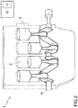
figure 2 is a schematic view of an internal combustion engine provided with a control unit implementing the method for detecting the anti-knocking capacity of a fuel according to the invention; -
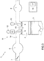
figure 3 is a schematic view of a cylinder of the internal combustion engine offigure 1 ; and -
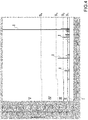
figure 4 shows, in a time/number of revolutions (rpm) plane, the intensity of detonation indexes; -
figure 5 is a map used to update the anti-knocking capacity of a fuel relative to a reference fuel after a refuelling; and -
figure 6 is a diagram used to update the anti-knocking capacity of a fuel relative to a reference fuel during the normal operation of the internal combustion engine offigure 2 . - In
figure 2 ,numeral 1 indicates, as a whole, an internal combustion engine with a controlled ignition comprising fourcylinders 2 arranged in line. Eachcylinder 2 houses arespective piston 3, which is mechanically connected, by means of a connecting rod, to adrive shaft 4, so as to transmit to thedrive shaft 4 itself the force generated by the combustion inside thecylinder 2. - According to
figure 2 , theinternal combustion engine 1 comprises anintake manifold 5, which is connected to eachcylinder 2 by means of two intake valves 6 (only one of them is shown infigure 3 ) and receives fresh air (i.e. air coming from the outside) through athrottle vale 7, which is movable between a closing position and a maximum opening position. Furthermore, theinternal combustion engine 1 comprises anexhaust manifold 8, which is connected to eachcylinder 2 by means of two exhaust valves 9 (only one of them is shown infigure 3 ) and leads into an emission pipe (not shown) to release the gases produced by the combustion into the atmosphere. - The position of the
intake valves 6 is controlled by a valveopening control device 11, which controls theintake valves 6, managing their opening angle (with a fixed lift) so as to control the torque delivered by means of theintake valves 6. The valveopening control device 11 uses atraditional camshaft 12 receiving the motion of thedrive shaft 4 and, for eachintake valve 6, comprises ahydraulic actuator 13, which is electrically controlled (i.e. controlled by means of a solenoid valve) and is interposed between a stem of theintake valve 6 and thecamshaft 12. - The position of each
exhaust valve 9 is controlled by a valve opening control device (similar to the valveopening control device 11 and not shown), which controls theexhaust valves 9, managing their opening angle (with a fixed lift). The valve opening control device uses acamshaft 10 receiving the motion of thedrive shaft 4 and, for eachexhaust valve 9, comprises an electrically controlled actuator (not shown). - For each
cylinder 2 there is provided acorresponding injector 14; according to the embodiment shown infigure 3 , the injection is an indirect injection and, therefore, eachinjector 14 is arranged upstream of thecylinder 2 in an intake pipe connecting theintake manifold 5 to thecylinder 2. According to an alternative embodiment, which is not shown herein, the injection is a direct injection and, therefore, eachinjector 14 is partially arranged inside thecylinder 2. - Furthermore, each
cylinder 2 comprises aspark plug 15, which is arranged through the crown end of thecylinder 2 in a central position between theintake valves 5 and theexhaust valves 9 and is cyclically activated so as to determine the ignition of the gases compressed inside thecylinder 2 at the end of each compression phase. - The
engine 1 comprises acontrol unit 16, which manages the operation ofcombustion engine 1 and, among other things, controls thespark plugs 15 so as to determine the ignition of the gases compressed inside eachcylinder 2. Thecontrol unit 16 comprises amemory 17, where a series of maps are stored, which provide values for controlling thespark plugs 15 based on the current engine point; in particular, for each spark plug 15 (namely, for each cylinder 2), the maps stored in thememory 17 provide a standard spark advance. Below you can find a description of the strategy implemented by thecontrol unit 16 to estimate the anti-knocking capacity of the fuel being used and to adjust the spark advance operated in theinternal combustion engine 1 to the anti-knocking capacity of the fuel being used. - The detonation control mode implemented by the
control unit 16 involves providing an indication of the intensity of the detonation phenomenon in theinternal combustion engine 1 through a proper treatment of a signal coming from one or more detonation sensors connected to thecontrol unit 16. According to a preferred variant, there is provided a detonation sensor for eachspark plug 15 suited to determine the ignition of the gases compressed inside arespective cylinder 2. - Each detonation sensor comprises a pressure measurer, which detects the maximum amplitude (MAPO - Maximum Amplitude Pressure Oscillation) of the intensity of the pressure waves generated in the
cylinders 2 of theinternal combustion engine 1. In particular, according to a preferred variant,number 16 generally indicates acontrol unit 16 consisting of a first electronic control unit, which is designed to detect the ionization currents to the electrodes of each one of thespark plugs 15 and to analyse the frequency content of said ionization currents. Thecontrol unit 16 is connected, via CAN, to an engine control unit, which applies the spark advance that is deemed to be necessary for eachcylinder 2 based one the corresponding signal coming from thecontrol unit 16. - The
control unit 16 is designed to determine a raw detonation index Iraw for eachcylinder 2 for each combustion as a function of the signal coming from the respective detonation sensor. Therefore, the raw detonation index Iraw is correlated with the maximum amplitude (APO - Maximum Amplitude Pressure Oscillation) of the intensity of the pressure waves generated in therespective cylinder 2 in the combustion being examined. After having calculated the raw detonation index Iraw for eachcylinder 2 and for each combustion, a detonation index I is calculated through the difference between the raw detonation index Iraw and a reference value Iref. Inside thecontrol unit 16 there is stored a map, which provides the reference value Iref as a function of the engine point; the reference value Iref represents the maximum amplitude of the intensity of the pressure waves generated in therespective cylinder 2 for each combustion cycle in the absence of detonation events. - Inside the
control unit 16 there are stored a plurality of threshold values, which identify, in turn, a plurality of detonation intervals. In particular, according to a preferred embodiment shown infigure 4 , inside thecontrol unit 16 there are stored four threshold values indicated with S1, S2, S3 and S4, respectively, which identify, in turn, five detonation intervals indicated with I, II, III, IV and V, respectively. The four threshold values indicated with S1, S2, S3 and S4, respectively, according tofigure 4 , can be adjusted as a function of the number of revolutions (rpm) or of the load. Therefore, inside thecontrol unit 16 there are stored the threshold values S1, S2, S3, S4 that define the five detonation intervals indicated with I, II, III, IV and V. - The detonation interval indicated with I comprises all the marginal detonation events characterized by a detonation index I below the threshold value S1. The detonation interval indicated with II includes all the detonation events with a reduced intensity characterized by a detonation index I comprised between the threshold values indicated with S1 and S2. The detonation interval indicated with III includes all the detonation events with a medium intensity characterized by a detonation index I comprised between the threshold values indicated with S2 and S3. The detonation interval indicated with IV includes all the detonation events with a high intensity characterized by a detonation index I comprised between the threshold values indicated with S3 and S4. Finally, the detonation interval indicated with V comprises all the detonation events with a very high intensity characterized by a detonation index I exceeding the threshold value S4.
- Inside the
control unit 16 there are stored a plurality of counters COUNTERi, which, in use, are updated during the strategy for estimating the anti-knocking capacity of the fuel. In particular, inside thecontrol unit 16 there are stored five counters COUNTERI, COUNTERII, COUNTERIII, COUNTERIV and COUNTERV, each associated with a respective detonation interval indicated with I, II, III, IV and V. In use, each counter COUNTERI, COUNTERII, COUNTERIII, COUNTERIV and COUNTERV is increased every time thecontrol unit 16 recognizes a combustion associated with a detonation index I comprised in the corresponding detonation interval indicated with I, II, III, IV and V. In other words, through the five counters COUNTERI, COUNTERII, COUNTERIII, COUNTERIV and COUNTERV, the control unit keeps count of how many marginal detonation events take place, of how many detonation events with a reduced intensity take place, of how many detonation events with a medium intensity take place and of how many detonation events with a very high intensity take place. Finally, thecontrol unit 16 is also designed to keep count of how many no-detonation events take place by means of a counter COUNTERno_det, which is increased every time thecontrol unit 16 recognizes a no-detonation combustion associated with a detonation index I that is basically equal to zero. We would also like to point out that the counter COUNTERno_det is increased every tome thecontrol unit 16 recognizes a no-detonation combustion exclusively in correspondence to the engine points (identified by the number of revolutions (rpm) and by the load) in which detonation events can actually take place; in other words, thecontrol unit 16 is designed to ignore, thus not updating the counter COUNTERno_det, every time it recognizes a no-detonation combustion of the engine points (identified by the number of revolutions (rpm) and by the load) in which detonation events cannot take place. - In use, the
control unit 16 is designed to recognize a refuelling; after a refuelling has been recognized, thecontrol unit 16 activates the strategy for estimating the anti-knocking capacity of the new fuel introduced with the refuelling, so as to adjust the spark advance operated to the anti-knocking capacity of the new fuel introduced with the refuelling. - First of all, the
control unit 16 checks whether the combustion being examined occurs in an engine point (identified by the number of revolutions (rpm) and by the load) in which detonation events can actually take place. In case the result of this first check is negative, namely if the combustion being examined occurs in an engine point in which detonation events cannot take place, thecontrol unit 16 is designed to ignore the current combustion and wait for the following combustion cycle. - Then the detonation index I of the current combustion is calculated through the difference between the raw detonation index Iraw (obtained, in turn, by processing the signal coming from the corresponding detonation sensor) and the reference value Iref.
- In case the result of the aforesaid first check is positive, namely if the current combustion occurs in an engine point in which detonation events can actually take place, the
control unit 16, first of all, checks whether during the combustion a detonation phenomenon has taken place or not. In case this check has a negative result, namely if no detonation events have occurred, the counter COUNTERno_det is increased and updated. In case this check has a positive result, namely if detonation events have occurred, thecontrol unit 16 compares the detonation index I of the current combustion with the threshold value S4. In case the detonation index I of the current combustion exceeds or is equal to the threshold value S4, the counter COUNTERV is updated. In other words, the number of detonation events with a very high intensity comprised in the detonation interval indicated with V is increased. In case the detonation index I of the current combustion is below the threshold value S4, thecontrol unit 16 compares the detonation index I of the current combustion with the threshold value S3. In case the detonation index I of the current combustion exceeds or is equal to the threshold value S3, the counter COUNTERIV is updated. In other words, the number of detonation events with a high intensity comprised in the detonation interval indicated with IV is increased. In case the detonation index I of the current combustion is below the threshold value S3, thecontrol unit 16 compares the detonation index I of the current combustion with the threshold value S2. - In case the detonation index I of the current combustion exceeds or is equal to the threshold value S2, the counter COUNTERIII is updated. In other words, the number of detonation events with a medium intensity comprised in the detonation interval indicated with III is increased. In case the detonation index I of the current combustion is below the threshold value S2, the
control unit 16 compares the detonation index I of the current combustion with the threshold value S1. - In case the detonation index I of the current combustion exceeds or is equal to the threshold value S1, the counter COUNTERII is updated. In other words, the number of detonation events with a low intensity comprised in the detonation interval indicated with II is increased. In case the detonation index I of the current combustion is below the threshold value S1, the counter COUNTERI is updated. In other words, the number of detonation events with a marginal intensity comprised in the detonation interval indicated with I is increased.
- In other words, the detonation index I of the current combustion is compared with the threshold values S1, S2, S3, S4 until one can determine the detonation interval to which the current combustion belongs. In case the combustion being examined takes place in an engine point in which detonation events can actually occur, the
control unit 16 also establishes whether a detonation event has not taken place or whether a detonation event with a marginal, reduced, medium, high or very high intensity has taken place, updating the corresponding counter COUNTERI, COUNTERII, COUNTERIII, COUNTERIV and COUNTERV. - Each one of the six counters COUNTERno_det, COUNTERI, COUNTERII, COUNTERIII, COUNTERIV and COUNTERV is associated with a corresponding threshold value TVCNTno_det, TVCNTI, TVCNTII, TVCNTIII, TVCNTIV and TVCNTV.
- The
control unit 16 checks the single combustion cycles until one of the six counters COUNTERno_det, COUNTERI, COUNTERII, COUNTERIII, COUNTERIV and COUNTERV reaches the corresponding threshold value TVCNTno_det, TVCNTIF, TVCNTII, TVCNTIII, TVCNTIV and TVCNTV. By so doing, a cycle for calculating the strategy for estimating the anti-knocking capacity of the new fuel introduced with the refuelling can be considered as concluded and all six counters COUNTERno_det, COUNTERI, COUNTERII, COUNTERIII, COUNTERIV and COUNTERV are zeroed. - Based on the counter COUNTERno_det, COUNTERI, COUNTERII, COUNTERIII, COUNTERIV and COUNTERV that has reached the corresponding threshold value TVCNTno_det, TVCNTI, TVCNTII, TVCNTIII, TVCNTIV and TVCNTV, the anti-knocking capacity of the fuel being used is updated or maintained.
- In particular, if the counter COUNTERno_det reaches the corresponding threshold value TVCNTno_det, this can mean that the fuel introduced with the refuelling has the same anti-knocking capacity as the previously used fuel and the operated spark advance does not need to be adjusted to the new fuel introduced with the refuelling. Alternatively, if the counter COUNTERno_det reaches the corresponding threshold value TVCNTno_det, this can mean that the fuel introduced with the refuelling is better than the previously used fuel; in this case, the anti-knocking capacity of the fuel being used in updated.
- In the other cases, if any one of the counters COUNTERI, COUNTERII, COUNTERIII, COUNTERIV and COUNTERV has reached the corresponding threshold value TVCNTI, TVCNTII, TVCNTIII, TVCNTIV and TVCNTV, this means that the fuel introduced with the refuelling has an anti-knocking capacity that is different from the anti-knocking capacity of the previously used fuel and, therefore, the operated spark advance needs to be adjusted to the anti-knocking capacity of the new fuel introduced with the refuelling.
- Furthermore, in a preliminary phase, a number of fuels were identified, in particular five fuels, based on their anti-knocking capacity. In particular, five fuel classes were identified, namely RON98+ identifies fuels with a high anti-knocking capacity, RON95 identifies fuels with a medium anti-knocking capacity, RON91 identifies fuels with a low anti-knocking capacity, and RON98/95 and RON95/91 identify fuels with an intermediate anti-knocking capacity comprised between the aforesaid values.
- Inside the
control unit 16 there is stored a map shown infigure 5 , which is consulted at the end of each cycle for calculating the strategy for estimating the anti-knocking capacity of the new fuel introduced with the refuelling. First of all, one calculates the mean spark advance SA operated by theinternal combustion engine 1 in the combustion cycles that caused the counter COUNTERno_det, COUNTERI, COUNTERII, COUNTERIII, COUNTERIV and COUNTERV to reach the corresponding threshold value TVCNTno_det, TVCNTI, TVCNTII, TVCNTIII, TVCNTIV and TVCNTV. Knowing which counter COUNTERno_det, COUNTERI, COUNTERII, COUNTERIII, COUNTERIV and COUNTERV has reached the corresponding threshold value TVCNTno_det, TVCNTIF, TVCNTII, TVCNTIII, TVCNTIV e TUCNTV and the mean spark advance SA operated by theinternal combustion engine 1 in the combustion cycles that caused said counter COUNTERno_det, COUNTERI, COUNTERII, COUNTERIII, COUNTERIV and COUNTERV to reach the corresponding threshold value TVCNTno_det, TVCNTI, TVCNTII, TVCNTIII, TVCNTIV and TVCNTV, the map indicates the variation to be applied to the anti-knocking capacity (i.e. to the current reference fuel level). - For example, we can assume that the cycle for calculating the strategy for estimating the anti-knocking capacity of the new fuel introduced with the refuelling has ended because the counter COUNTERIV has reached the corresponding threshold value TVCNTIV (equal to six detonation events recognized in the detonation interval IV) starting from a reference fuel with a mean anti-knocking capacity RON95. The six detonation events recognized in the detonation interval IV took place in combustion cycles in which the spark advance SA operated by the
internal combustion engine 1 assumed the following values:Detonation event SA (°) 1 - 3.50 2 - 2.25 3 - 5.25 4 - 0.75 5 0 6 0 - The mean spark advance SA operated by the
internal combustion engine 1 in the six combustion cycles that caused the counter COUNTERIV to reach the corresponding threshold value TVCNTIV is equal to - 1.96°. - Consulting the map shown in
figure 5 , one can establish that, in case the counter COUNTERIV has reached the corresponding threshold value TVCNTIV operating a mean spark advance SA equal to - 2° in the six combustion cycles characterized by detonation events, the variation to be applied to the anti-knocking capacity (i.e. relative to the reference fuel level) is equal to +1. The reference fuel is then updated to the fuel with a smaller anti-knocking capacity, namely with an intermediate anti-knocking capacity RON91/95. - The cycle described above for calculating the strategy for estimating the anti-knocking capacity of the new fuel introduced with the refuelling is repeated n1 times, wherein n1 is an adjustable value, which is determined in a set up phase of the
control unit 16. Said n1 reference fuels determined at the end of each calculation cycle are stored in a vector of thecontrol unit 16 and, at the end of said n1 calculation cycles, the strategy for estimating the anti-knocking capacity of the new fuel introduced with the refuelling is considered as concluded. - The
control unit 16 is designed to establish that the anti-knocking capacity of the new fuel introduced with the refuelling is equal to the greatest anti-knocking capacity among those of the n2 reference fuels determined at the end of the last n2 calculation cycles stored in the vector; wherein n2 is an adjustable value, which is determined in a set up phase of thecontrol unit 16 and is preferably smaller than n1. - Each one of the five fuels identified based on their anti-knocking capacity is associated with a map stored in the
control unit 16, which, depending on the engine point, i.e. on the number of revolutions (rpm) and on the load), provides the variation of the spark advance to be applied. Therefore, in use, besides the variation of the spark advance deriving from the detonation control strategy (namely, the strategy used to avoid the occurrence of detonation phenomena), a further variation of the spark advance is applied, which is due to the anti-knocking capacity of the fuel being used. Hence, the strategy for estimating the anti-knocking capacity of the new fuel introduced with the refuelling, involves correcting the spark advance to be operated as a function of the greatest anti-knocking capacity included in the second number n2 of values of the anti-knocking capacity of the fuel introduced with the refuelling. - The strategy described above for estimating the anti-knocking capacity of the new fuel introduced with the refuelling can be also used, with some changes, during the normal operation of the
internal combustion engine 1. In this case, as well, the calculation cycles are carried out exactly as described above, using the six counters COUNTERno_det, COUNTERI, COUNTERII, COUNTERIII, COUNTERIV and COUNTERV and the respective threshold values TVCNTno_det, TVCNTI, TVCNTII, TVCNTIII, TVCNTIV and TVCNTV. - In the
control unit 16 there are stored three variables indicated with CNTPOS, CNTNULL and CNTNEG, respectively. At the end of each calculation cycle, one of the three variables CNTPOS, CNTNULL and CNTNEG is updated based on the variation to be applied to the anti-knocking capacity (relative to the reference fuel level) provided by the map shown infigure 5 . In case the reference fuel needs to be updated to the fuel with a greater anti-knocking capacity, the variable CNTPOS is increased; in case the reference fuel needs to be updated to the fuel with a smaller anti-knocking capacity, the variable CNTNEG is updated; and, finally, in case there is no need to update the reference fuel, the variable CNTNULL is increased. - The cycle for calculating the strategy for estimating the anti-knocking capacity of the fuel is repeated n3 times, wherein n3 is an adjustable value, which is determined in a set up phase of the
control unit 16 and, for example, is equal to 10. At the end of each one of the ten calculation cycles, one of the three variables CNTPOS CNTNULL and CNTNEG is updated. - Finally, two vectors are defined, which are indicated with RUNPOS and RUNNEG (adjustable in a set up phase of the control unit 16) and define the maximum number of combustion cycles that are necessary to update the reference fuel to the fuel with a greater anti-knocking capacity and the minimum number of combustion cycles that are necessary to update the reference fuel to the fuel with a smaller anti-knocking capacity. The development of the two vectors RUNPOS and RUNNEG is graphically represented by two broken lines in the plane CNTPOS - CNTNEG shown in
figure 6 . - If, at the end of the cycle for calculating the strategy for estimating the anti-knocking capacity of the fuel, the point defined by the variables CNTPOS - CNTNEG is located in the portion of the diagram of
figure 6 subtended by the vector RUNPOS, the reference fuel is updated to the fuel with a smaller anti-knocking capacity. If, at the end of the cycle for calculating the strategy for estimating the anti-knocking capacity of the fuel, the point defined by the variables CNTPOS - CNTNEG is located in the portion of the diagram offigure 6 above the vector RUNNEG, the reference fuel is updated to the fuel with a greater anti-knocking capacity. If, at the end of the cycle for calculating the strategy for estimating the anti-knocking capacity of the fuel, the point defined by the variables CNTPOS - CNTNEG is located in the portion of the diagram offigure 6 comprised between the vector RUNPOS and the vector RUNNEG, the reference fuel is not updated. - For example, at the end of said ten calculation cycles, the following cases can occur:
A B C CNT POS 2 1 1 CNT NULL3 3 1 CNT NEG5 6 8 - In case A indicated in the diagram of
figure 6 , the reference fuel is updated to the fuel with a smaller anti-knocking capacity; in case C indicated in the diagram offigure 6 , the reference fuel is updated to the fuel with a greater anti-knocking capacity; whereas, in case B, which is also indicated in the diagram offigure 6 , the reference fuel is not updated. - According to a variant, the
internal combustion engine 1 is provided with eightcylinders 2 and with twocontrol units 16, which are connected to one another via CAN and are each connected to fourcylinders 2. Each one of the twocontrol units 16 is designed to implement the strategy for recognizing the anti-knocking capacity of a fuel introduced after a refuelling independently of one another. The anti-knocking capacity of the fuel introduced after a refuelling is equal to the worst anti-knocking capacity between the ones determined in an independent manner by the twocontrol units 16. For example, if afirst control unit 16 recognizes a fuel with an anti-knocking capacity RON95/91 and asecond control unit 16 recognizes a fuel with an anti-knocking capacity RON95, then the anti-knocking capacity of the fuel introduced after the refuelling is established to be RON95/91. - The method described above for detecting the anti-knocking capacity of a fuel in an internal combustion engine has many advantages. In particular, the strategy described above is simple and cheap to be implemented in a
control unit 16, as it does not require any physical changes and use a small calculation capacity of thecontrol unit 16 itself. Furthermore, the method described above allows you to effectively recognize the anti-knocking capacity of a fuel introduced after a refuelling and to adjust the operated spark advance to said fuel without significant negative effects on the efficiency of the combustions (which is kept close to the maximum possible values with clear benefits for consumptions and pollution containment) and preventing the repetition of high-intensity detonation phenomena from causing damages to the components of theinternal combustion engine 1.
Claims (8)
- A method for detecting the anti-knocking capacity of a fuel in an internal combustion engine (1) provided with a number of cylinders (2); the method comprising:identifying a plurality of fuels (RON98+, RON98/95, RON95, RON95/91, RON91) as a function of their anti-knocking capacity;identifying a reference fuel among the plurality of fuels;an analysis step to analyse the single combustion cycles of the cylinders (2) comprising the following substeps:- determining a detonation index (I) for each combustion; wherein the detonation index (I) is calculated through the difference between a raw detonation index (Iraw), which is correlated with the maximum amplitude of the intensity of the pressure waves generated in a cylinder (2) during the combustion, and a reference value (Iref), which represents the maximum amplitude of the intensity of the pressure waves generated in the cylinder (2) for each combustion cycle in the absence of detonating events;- - comparing the detonation index (I) with a number of threshold values S1, S2, S3, S4), which define a number of detonation intervals (I, II, III, IV, V); each one of said detonation intervals (I, II, III, IV, V) defines detonating events, which substantially have the same intensity; and- - increasing a first counter COUNTERno_det, COUNTERI, COUNTERII, COUNTERIII, COUNTERIV, COUNTERV) associated with the detonation interval (I, II, III, IV, V) in which the detonation index (I) is included;repeating the analysis step to analyse the single combustion cycles of the cylinders (2) until the moment in which any one of the first counters (COUNTERno_det, COUNTERI, COUNTERII, COUNTERIII, COUNTERIV, COUNTERV) reaches a respective limit value (TVCNTno_det, TVCNTI, TVCNTII, TVCNTIII, TVCNTIV e TVCNTV) ;calculating the mean spark advance (SA) operated by the internal combustion engine (1) in the single combustion cycles of the cylinders (2) that have allowed said first counter to reach the respective limit value; anddetermining the variation to be applied to the anti-knocking capacity of the reference fuel as a function both of the first counter (COUNTERno_det, COUNTERI, COUNTERII, COUNTERIII, COUNTERIV, COUNTERV) that has reached the respective limit value (TVCNTno_det, TVCNTI, TVCNTII, TVCNTIII, TVCNTIV e TVCNTV) and of the mean spark advance (SA) operated by the internal combustion engine in the single combustion cycles of the cylinders (2) that have allowed said first counter to reach the respective limit value.
- A method according to any of the previous claims and comprising the further step of ignoring the single combustion cycles of the cylinders (2) that take place in correspondence to engine points determined by the number of revolutions per minute (rpm) and by the load, in which no detonating events can occur.
- A method according to any of the previous claims and comprising the further steps of:detecting when a refuelling takes place;zeroing each first counter (COUNTERno_det, COUNTERI, COUNTERII, COUNTERIII, COUNTERIV, COUNTERV);repeating a first number (n1) of analysis cycles, so as to determine a number of values of the anti-knocking capacity of the fuel introduced with the refuelling, which is equal to said first number (n1) of analysis cycles; anddetermining a correction of the spark advance to be operated as a function of a second number (n2) of values of the anti-knocking capacity of the fuel introduced with the refuelling; wherein the second number (n2) of values represents a group of said first number (n1) of analysis cycles and, in particular, the last ones in time order.
- A method according to claim 3 and comprising the further step of determining the correction of the spark advance to be operated as a function of the greatest anti-knocking capacity included in the second number (n2) of values of the anti-knocking capacity of the fuel introduced with the refuelling.
- A method according to claim 3 or 4 and comprising the further step of zeroing each first counter (COUNTERno_det, COUNTERI, COUNTERII, COUNTERIII, COUNTERIV, COUNTERV) after having determined each one of said first number (n1) of values of the anti-knocking capacity of the fuel introduced with the refuelling.
- A method according to any of the previous claims and comprising, during the normal operation of the internal combustion engine (1), the further step of increasing a second counter (CNTPOS, CNTNULL, CNTNEG), in case the variation to be applied to the anti-knocking capacity of the reference fuel, as a function of the counter (COUNTERno_det, COUNTERI, COUNTERII, COUNTERIII, COUNTERIV, COUNTERV) that has reached the respective limit value (TVCNTno_det, TVCNTI, TVCNTII, TVCNTIII, TUCNTIV e TUCNTV) and as a function of the mean spark advance (SA) operated by the internal combustion engine (1) in the single combustion cycles of the cylinders (2) that have allowed said counter to reach the respective limit value, alternatively is positive or null or negative.
- A method according to claim 6 and comprising the further steps of:repeating a third number (n3) of analysis cycles, so as to determine a number of variations to be applied to the anti-knocking capacity of the reference fuel, which is equal to the third number (n3) of analysis cycles and so as to update said three second counters for a number of times that is equal to the third number (n3) of analysis cycles;comparing said three second counters (CNTPOS, CNTNULL, CNTNEG) at the end of the third number (n3) of analysis cycles with two vectors, which respectively define the maximum number of analysis cycles that are necessary to update the reference fuel to the fuel with a greater anti-knocking capacity and the minimum number of analysis cycles that are necessary to update the reference fuel to the fuel with a smaller anti-knocking capacity; anddetermining the variation to be applied to the anti-knocking capacity of the reference fuel as a function of the comparison between said three second counters (CNTPOS, CNTNULL, CNTNEG) at the end of the third number (n3) of analysis cycles and the two vectors.
- An electronic control unit (16), which is designed to implement a method for detecting the anti-knocking capacity of a fuel in an internal combustion engine (1) performed according to one or more of the claims from 1 to 7.
Applications Claiming Priority (1)
| Application Number | Priority Date | Filing Date | Title |
|---|---|---|---|
| ITUB2015A003390A ITUB20153390A1 (en) | 2015-09-03 | 2015-09-03 | METHOD FOR RECOGNIZING THE ANTI-DETONING POWER OF A FUEL IN AN INTERNAL COMBUSTION ENGINE |
Publications (2)
| Publication Number | Publication Date |
|---|---|
| EP3139023A1 true EP3139023A1 (en) | 2017-03-08 |
| EP3139023B1 EP3139023B1 (en) | 2018-12-19 |
Family
ID=54843954
Family Applications (1)
| Application Number | Title | Priority Date | Filing Date |
|---|---|---|---|
| EP16187139.7A Active EP3139023B1 (en) | 2015-09-03 | 2016-09-02 | Method for detecting the anti-knocking capacity of a fuel in an internal combustion engine |
Country Status (3)
| Country | Link |
|---|---|
| US (1) | US10125736B2 (en) |
| EP (1) | EP3139023B1 (en) |
| IT (1) | ITUB20153390A1 (en) |
Families Citing this family (2)
| Publication number | Priority date | Publication date | Assignee | Title |
|---|---|---|---|---|
| EP3737854B1 (en) * | 2018-01-12 | 2024-03-27 | Cummins, Inc. | Systems and method for harmonizing knock in engine cylinders |
| IT201900004875A1 (en) * | 2019-04-01 | 2020-10-01 | Magneti Marelli Spa | METHOD FOR THE CONTROL OF THE COMBUSTION OF AN INTERNAL COMBUSTION ENGINE |
Citations (7)
| Publication number | Priority date | Publication date | Assignee | Title |
|---|---|---|---|---|
| US4708113A (en) * | 1984-09-28 | 1987-11-24 | Toyota Jidosha Kabushiki Kaisha | Method of discriminating octane number of fuel for motor vehicle |
| US4711212A (en) * | 1985-11-26 | 1987-12-08 | Nippondenso Co., Ltd. | Anti-knocking in internal combustion engine |
| US4716873A (en) * | 1985-09-05 | 1988-01-05 | Mazda Motor Corporation | Engine control system |
| US5040510A (en) * | 1989-05-23 | 1991-08-20 | Siemens Aktiengesellschaft | Method for controlling knocking in internal combustion engines |
| US5131369A (en) * | 1990-08-11 | 1992-07-21 | Honda Giken Kogyo Kabushiki Kaisha | Ignition timing control system for internal combustion engine |
| JPH09158819A (en) * | 1995-12-12 | 1997-06-17 | Hitachi Ltd | Engine ignition timing control device |
| US6283093B1 (en) * | 1996-02-14 | 2001-09-04 | Daimlerchrysler Ag | Method and apparatus for determining the ignition angle for an internal combustion engine with adaptive knocking |
Family Cites Families (4)
| Publication number | Priority date | Publication date | Assignee | Title |
|---|---|---|---|---|
| US4376429A (en) * | 1981-06-23 | 1983-03-15 | Ford Motor Company | Adaptive cylinder by cylinder knock retard control |
| US6947830B1 (en) * | 2004-08-31 | 2005-09-20 | Walt Froloff | Adaptive variable fuel internal combustion engine |
| JP2008291717A (en) * | 2007-05-23 | 2008-12-04 | Honda Motor Co Ltd | Control device for premixed compression ignition engine |
| US8347857B2 (en) * | 2010-06-24 | 2013-01-08 | GM Global Technology Operations LLC | Method and device for improving charged engines |
-
2015
- 2015-09-03 IT ITUB2015A003390A patent/ITUB20153390A1/en unknown
-
2016
- 2016-09-01 US US15/254,398 patent/US10125736B2/en active Active
- 2016-09-02 EP EP16187139.7A patent/EP3139023B1/en active Active
Patent Citations (7)
| Publication number | Priority date | Publication date | Assignee | Title |
|---|---|---|---|---|
| US4708113A (en) * | 1984-09-28 | 1987-11-24 | Toyota Jidosha Kabushiki Kaisha | Method of discriminating octane number of fuel for motor vehicle |
| US4716873A (en) * | 1985-09-05 | 1988-01-05 | Mazda Motor Corporation | Engine control system |
| US4711212A (en) * | 1985-11-26 | 1987-12-08 | Nippondenso Co., Ltd. | Anti-knocking in internal combustion engine |
| US5040510A (en) * | 1989-05-23 | 1991-08-20 | Siemens Aktiengesellschaft | Method for controlling knocking in internal combustion engines |
| US5131369A (en) * | 1990-08-11 | 1992-07-21 | Honda Giken Kogyo Kabushiki Kaisha | Ignition timing control system for internal combustion engine |
| JPH09158819A (en) * | 1995-12-12 | 1997-06-17 | Hitachi Ltd | Engine ignition timing control device |
| US6283093B1 (en) * | 1996-02-14 | 2001-09-04 | Daimlerchrysler Ag | Method and apparatus for determining the ignition angle for an internal combustion engine with adaptive knocking |
Also Published As
| Publication number | Publication date |
|---|---|
| US20170089316A1 (en) | 2017-03-30 |
| ITUB20153390A1 (en) | 2017-03-03 |
| EP3139023B1 (en) | 2018-12-19 |
| US10125736B2 (en) | 2018-11-13 |
Similar Documents
| Publication | Publication Date | Title |
|---|---|---|
| US9291125B2 (en) | Gas engine, control system and control method for gas engine | |
| US9316556B2 (en) | Knock control apparatus for an internal combustion engine | |
| US20150226144A1 (en) | Method for balancing cylinders of an internal combustion engine | |
| CN110748430B (en) | Control method and system for EGR (exhaust gas recirculation) correction knocking of natural gas engine | |
| US20180066593A1 (en) | Control Device for Internal Combustion Engine and Abnormal Combustion Detecting Method | |
| US10280848B2 (en) | Internal combustion engine control apparatus | |
| US8924134B2 (en) | Knock control device of internal combustion engine | |
| ITBO20090665A1 (en) | METHOD OF CHECKING DETONATION IN AN INTERNAL COMBUSTION ENGINE PROVIDED WITH A SUCTION VALVE OPENING DEVICE | |
| EP3139023B1 (en) | Method for detecting the anti-knocking capacity of a fuel in an internal combustion engine | |
| US10519879B2 (en) | Determining in-cylinder pressure by analyzing current of a spark plug | |
| US9322382B2 (en) | Method for detecting detonation phenomena in an internal combustion engine | |
| US20100031923A1 (en) | Method and Apparatus for Detecting Engine Knock | |
| JP6845067B2 (en) | Internal combustion engine controller | |
| JP2010174737A (en) | Control device for diesel engine | |
| JP2015014229A (en) | Abnormal combustion avoidance device for internal combustion engine | |
| KR20200009149A (en) | A method of operating an internal combustion piston engine, a control system for controlling the operation of an internal combustion piston engine, and an internal combustion piston engine | |
| JP6607138B2 (en) | Exhaust gas recirculation control device for internal combustion engine | |
| JP7124516B2 (en) | Combustion control device for internal combustion engine | |
| US9784204B2 (en) | Method to detect and control detonation phenomena in an internal combustion engine | |
| JP2015083814A (en) | Control device of internal combustion engine | |
| JP6252201B2 (en) | Abnormal combustion detector | |
| JP6696292B2 (en) | Misfire detector | |
| JP2018135793A (en) | Spark ignition type internal combustion engine | |
| JP2020070725A (en) | Fuel injection system for internal combustion engine | |
| ITUA20164481A1 (en) | METHOD FOR THE CONTROL OF DETONATION PHENOMENA IN AN INTERNAL COMBUSTION ENGINE |
Legal Events
| Date | Code | Title | Description |
|---|---|---|---|
| PUAI | Public reference made under article 153(3) epc to a published international application that has entered the european phase |
Free format text: ORIGINAL CODE: 0009012 |
|
| STAA | Information on the status of an ep patent application or granted ep patent |
Free format text: STATUS: THE APPLICATION HAS BEEN PUBLISHED |
|
| AK | Designated contracting states |
Kind code of ref document: A1 Designated state(s): AL AT BE BG CH CY CZ DE DK EE ES FI FR GB GR HR HU IE IS IT LI LT LU LV MC MK MT NL NO PL PT RO RS SE SI SK SM TR |
|
| AX | Request for extension of the european patent |
Extension state: BA ME |
|
| STAA | Information on the status of an ep patent application or granted ep patent |
Free format text: STATUS: REQUEST FOR EXAMINATION WAS MADE |
|
| 17P | Request for examination filed |
Effective date: 20170907 |
|
| GRAP | Despatch of communication of intention to grant a patent |
Free format text: ORIGINAL CODE: EPIDOSNIGR1 |
|
| STAA | Information on the status of an ep patent application or granted ep patent |
Free format text: STATUS: GRANT OF PATENT IS INTENDED |
|
| RIC1 | Information provided on ipc code assigned before grant |
Ipc: F02P 17/00 20060101ALI20180601BHEP Ipc: F02D 41/24 20060101ALI20180601BHEP Ipc: F02D 41/14 20060101ALI20180601BHEP Ipc: F02D 19/06 20060101ALI20180601BHEP Ipc: F02D 41/00 20060101AFI20180601BHEP Ipc: F02D 35/02 20060101ALI20180601BHEP Ipc: G01M 15/08 20060101ALI20180601BHEP Ipc: F02P 5/152 20060101ALI20180601BHEP Ipc: G01L 23/22 20060101ALI20180601BHEP |
|
| INTG | Intention to grant announced |
Effective date: 20180622 |
|
| RIN1 | Information on inventor provided before grant (corrected) |
Inventor name: MARCIGLIANO, FRANCESCO Inventor name: PAOLIN, SIMONE Inventor name: POGGIO, LUCA Inventor name: SARTONI, GIOVANNI |
|
| GRAS | Grant fee paid |
Free format text: ORIGINAL CODE: EPIDOSNIGR3 |
|
| GRAJ | Information related to disapproval of communication of intention to grant by the applicant or resumption of examination proceedings by the epo deleted |
Free format text: ORIGINAL CODE: EPIDOSDIGR1 |
|
| GRAL | Information related to payment of fee for publishing/printing deleted |
Free format text: ORIGINAL CODE: EPIDOSDIGR3 |
|
| STAA | Information on the status of an ep patent application or granted ep patent |
Free format text: STATUS: REQUEST FOR EXAMINATION WAS MADE |
|
| GRAR | Information related to intention to grant a patent recorded |
Free format text: ORIGINAL CODE: EPIDOSNIGR71 |
|
| STAA | Information on the status of an ep patent application or granted ep patent |
Free format text: STATUS: GRANT OF PATENT IS INTENDED |
|
| GRAA | (expected) grant |
Free format text: ORIGINAL CODE: 0009210 |
|
| STAA | Information on the status of an ep patent application or granted ep patent |
Free format text: STATUS: THE PATENT HAS BEEN GRANTED |
|
| INTC | Intention to grant announced (deleted) | ||
| INTG | Intention to grant announced |
Effective date: 20181108 |
|
| AK | Designated contracting states |
Kind code of ref document: B1 Designated state(s): AL AT BE BG CH CY CZ DE DK EE ES FI FR GB GR HR HU IE IS IT LI LT LU LV MC MK MT NL NO PL PT RO RS SE SI SK SM TR |
|
| REG | Reference to a national code |
Ref country code: GB Ref legal event code: FG4D |
|
| REG | Reference to a national code |
Ref country code: CH Ref legal event code: EP |
|
| REG | Reference to a national code |
Ref country code: IE Ref legal event code: FG4D |
|
| REG | Reference to a national code |
Ref country code: DE Ref legal event code: R096 Ref document number: 602016008378 Country of ref document: DE |
|
| REG | Reference to a national code |
Ref country code: AT Ref legal event code: REF Ref document number: 1078977 Country of ref document: AT Kind code of ref document: T Effective date: 20190115 |
|
| REG | Reference to a national code |
Ref country code: NL Ref legal event code: MP Effective date: 20181219 |
|
| PG25 | Lapsed in a contracting state [announced via postgrant information from national office to epo] |
Ref country code: LV Free format text: LAPSE BECAUSE OF FAILURE TO SUBMIT A TRANSLATION OF THE DESCRIPTION OR TO PAY THE FEE WITHIN THE PRESCRIBED TIME-LIMIT Effective date: 20181219 Ref country code: FI Free format text: LAPSE BECAUSE OF FAILURE TO SUBMIT A TRANSLATION OF THE DESCRIPTION OR TO PAY THE FEE WITHIN THE PRESCRIBED TIME-LIMIT Effective date: 20181219 Ref country code: NO Free format text: LAPSE BECAUSE OF FAILURE TO SUBMIT A TRANSLATION OF THE DESCRIPTION OR TO PAY THE FEE WITHIN THE PRESCRIBED TIME-LIMIT Effective date: 20190319 Ref country code: BG Free format text: LAPSE BECAUSE OF FAILURE TO SUBMIT A TRANSLATION OF THE DESCRIPTION OR TO PAY THE FEE WITHIN THE PRESCRIBED TIME-LIMIT Effective date: 20190319 Ref country code: HR Free format text: LAPSE BECAUSE OF FAILURE TO SUBMIT A TRANSLATION OF THE DESCRIPTION OR TO PAY THE FEE WITHIN THE PRESCRIBED TIME-LIMIT Effective date: 20181219 Ref country code: LT Free format text: LAPSE BECAUSE OF FAILURE TO SUBMIT A TRANSLATION OF THE DESCRIPTION OR TO PAY THE FEE WITHIN THE PRESCRIBED TIME-LIMIT Effective date: 20181219 |
|
| REG | Reference to a national code |
Ref country code: LT Ref legal event code: MG4D |
|
| REG | Reference to a national code |
Ref country code: AT Ref legal event code: MK05 Ref document number: 1078977 Country of ref document: AT Kind code of ref document: T Effective date: 20181219 |
|
| PG25 | Lapsed in a contracting state [announced via postgrant information from national office to epo] |
Ref country code: SE Free format text: LAPSE BECAUSE OF FAILURE TO SUBMIT A TRANSLATION OF THE DESCRIPTION OR TO PAY THE FEE WITHIN THE PRESCRIBED TIME-LIMIT Effective date: 20181219 Ref country code: GR Free format text: LAPSE BECAUSE OF FAILURE TO SUBMIT A TRANSLATION OF THE DESCRIPTION OR TO PAY THE FEE WITHIN THE PRESCRIBED TIME-LIMIT Effective date: 20190320 Ref country code: AL Free format text: LAPSE BECAUSE OF FAILURE TO SUBMIT A TRANSLATION OF THE DESCRIPTION OR TO PAY THE FEE WITHIN THE PRESCRIBED TIME-LIMIT Effective date: 20181219 Ref country code: RS Free format text: LAPSE BECAUSE OF FAILURE TO SUBMIT A TRANSLATION OF THE DESCRIPTION OR TO PAY THE FEE WITHIN THE PRESCRIBED TIME-LIMIT Effective date: 20181219 |
|
| PG25 | Lapsed in a contracting state [announced via postgrant information from national office to epo] |
Ref country code: NL Free format text: LAPSE BECAUSE OF FAILURE TO SUBMIT A TRANSLATION OF THE DESCRIPTION OR TO PAY THE FEE WITHIN THE PRESCRIBED TIME-LIMIT Effective date: 20181219 |
|
| PG25 | Lapsed in a contracting state [announced via postgrant information from national office to epo] |
Ref country code: CZ Free format text: LAPSE BECAUSE OF FAILURE TO SUBMIT A TRANSLATION OF THE DESCRIPTION OR TO PAY THE FEE WITHIN THE PRESCRIBED TIME-LIMIT Effective date: 20181219 Ref country code: PT Free format text: LAPSE BECAUSE OF FAILURE TO SUBMIT A TRANSLATION OF THE DESCRIPTION OR TO PAY THE FEE WITHIN THE PRESCRIBED TIME-LIMIT Effective date: 20190419 Ref country code: ES Free format text: LAPSE BECAUSE OF FAILURE TO SUBMIT A TRANSLATION OF THE DESCRIPTION OR TO PAY THE FEE WITHIN THE PRESCRIBED TIME-LIMIT Effective date: 20181219 Ref country code: PL Free format text: LAPSE BECAUSE OF FAILURE TO SUBMIT A TRANSLATION OF THE DESCRIPTION OR TO PAY THE FEE WITHIN THE PRESCRIBED TIME-LIMIT Effective date: 20181219 |
|
| PG25 | Lapsed in a contracting state [announced via postgrant information from national office to epo] |
Ref country code: IS Free format text: LAPSE BECAUSE OF FAILURE TO SUBMIT A TRANSLATION OF THE DESCRIPTION OR TO PAY THE FEE WITHIN THE PRESCRIBED TIME-LIMIT Effective date: 20190419 Ref country code: SK Free format text: LAPSE BECAUSE OF FAILURE TO SUBMIT A TRANSLATION OF THE DESCRIPTION OR TO PAY THE FEE WITHIN THE PRESCRIBED TIME-LIMIT Effective date: 20181219 Ref country code: RO Free format text: LAPSE BECAUSE OF FAILURE TO SUBMIT A TRANSLATION OF THE DESCRIPTION OR TO PAY THE FEE WITHIN THE PRESCRIBED TIME-LIMIT Effective date: 20181219 Ref country code: SM Free format text: LAPSE BECAUSE OF FAILURE TO SUBMIT A TRANSLATION OF THE DESCRIPTION OR TO PAY THE FEE WITHIN THE PRESCRIBED TIME-LIMIT Effective date: 20181219 Ref country code: EE Free format text: LAPSE BECAUSE OF FAILURE TO SUBMIT A TRANSLATION OF THE DESCRIPTION OR TO PAY THE FEE WITHIN THE PRESCRIBED TIME-LIMIT Effective date: 20181219 |
|
| REG | Reference to a national code |
Ref country code: DE Ref legal event code: R097 Ref document number: 602016008378 Country of ref document: DE |
|
| PLBE | No opposition filed within time limit |
Free format text: ORIGINAL CODE: 0009261 |
|
| STAA | Information on the status of an ep patent application or granted ep patent |
Free format text: STATUS: NO OPPOSITION FILED WITHIN TIME LIMIT |
|
| PG25 | Lapsed in a contracting state [announced via postgrant information from national office to epo] |
Ref country code: DK Free format text: LAPSE BECAUSE OF FAILURE TO SUBMIT A TRANSLATION OF THE DESCRIPTION OR TO PAY THE FEE WITHIN THE PRESCRIBED TIME-LIMIT Effective date: 20181219 Ref country code: AT Free format text: LAPSE BECAUSE OF FAILURE TO SUBMIT A TRANSLATION OF THE DESCRIPTION OR TO PAY THE FEE WITHIN THE PRESCRIBED TIME-LIMIT Effective date: 20181219 |
|
| 26N | No opposition filed |
Effective date: 20190920 |
|
| PG25 | Lapsed in a contracting state [announced via postgrant information from national office to epo] |
Ref country code: SI Free format text: LAPSE BECAUSE OF FAILURE TO SUBMIT A TRANSLATION OF THE DESCRIPTION OR TO PAY THE FEE WITHIN THE PRESCRIBED TIME-LIMIT Effective date: 20181219 |
|
| PG25 | Lapsed in a contracting state [announced via postgrant information from national office to epo] |
Ref country code: TR Free format text: LAPSE BECAUSE OF FAILURE TO SUBMIT A TRANSLATION OF THE DESCRIPTION OR TO PAY THE FEE WITHIN THE PRESCRIBED TIME-LIMIT Effective date: 20181219 |
|
| PG25 | Lapsed in a contracting state [announced via postgrant information from national office to epo] |
Ref country code: MC Free format text: LAPSE BECAUSE OF FAILURE TO SUBMIT A TRANSLATION OF THE DESCRIPTION OR TO PAY THE FEE WITHIN THE PRESCRIBED TIME-LIMIT Effective date: 20181219 |
|
| REG | Reference to a national code |
Ref country code: CH Ref legal event code: PL |
|
| PG25 | Lapsed in a contracting state [announced via postgrant information from national office to epo] |
Ref country code: LU Free format text: LAPSE BECAUSE OF NON-PAYMENT OF DUE FEES Effective date: 20190902 Ref country code: IE Free format text: LAPSE BECAUSE OF NON-PAYMENT OF DUE FEES Effective date: 20190902 Ref country code: LI Free format text: LAPSE BECAUSE OF NON-PAYMENT OF DUE FEES Effective date: 20190930 Ref country code: CH Free format text: LAPSE BECAUSE OF NON-PAYMENT OF DUE FEES Effective date: 20190930 |
|
| REG | Reference to a national code |
Ref country code: BE Ref legal event code: MM Effective date: 20190930 |
|
| PG25 | Lapsed in a contracting state [announced via postgrant information from national office to epo] |
Ref country code: BE Free format text: LAPSE BECAUSE OF NON-PAYMENT OF DUE FEES Effective date: 20190930 |
|
| PG25 | Lapsed in a contracting state [announced via postgrant information from national office to epo] |
Ref country code: FR Free format text: LAPSE BECAUSE OF NON-PAYMENT OF DUE FEES Effective date: 20190930 |
|
| PG25 | Lapsed in a contracting state [announced via postgrant information from national office to epo] |
Ref country code: CY Free format text: LAPSE BECAUSE OF FAILURE TO SUBMIT A TRANSLATION OF THE DESCRIPTION OR TO PAY THE FEE WITHIN THE PRESCRIBED TIME-LIMIT Effective date: 20181219 |
|
| PG25 | Lapsed in a contracting state [announced via postgrant information from national office to epo] |
Ref country code: HU Free format text: LAPSE BECAUSE OF FAILURE TO SUBMIT A TRANSLATION OF THE DESCRIPTION OR TO PAY THE FEE WITHIN THE PRESCRIBED TIME-LIMIT; INVALID AB INITIO Effective date: 20160902 Ref country code: MT Free format text: LAPSE BECAUSE OF FAILURE TO SUBMIT A TRANSLATION OF THE DESCRIPTION OR TO PAY THE FEE WITHIN THE PRESCRIBED TIME-LIMIT Effective date: 20181219 |
|
| PG25 | Lapsed in a contracting state [announced via postgrant information from national office to epo] |
Ref country code: MK Free format text: LAPSE BECAUSE OF FAILURE TO SUBMIT A TRANSLATION OF THE DESCRIPTION OR TO PAY THE FEE WITHIN THE PRESCRIBED TIME-LIMIT Effective date: 20181219 |
|
| P01 | Opt-out of the competence of the unified patent court (upc) registered |
Effective date: 20230525 |
|
| PGFP | Annual fee paid to national office [announced via postgrant information from national office to epo] |
Ref country code: DE Payment date: 20250926 Year of fee payment: 10 |
|
| PGFP | Annual fee paid to national office [announced via postgrant information from national office to epo] |
Ref country code: IT Payment date: 20250908 Year of fee payment: 10 |
|
| PGFP | Annual fee paid to national office [announced via postgrant information from national office to epo] |
Ref country code: GB Payment date: 20250923 Year of fee payment: 10 |