EP3139004A1 - Turbine blade with ultrasonic wave scattering feature - Google Patents
Turbine blade with ultrasonic wave scattering feature Download PDFInfo
- Publication number
- EP3139004A1 EP3139004A1 EP15183454.6A EP15183454A EP3139004A1 EP 3139004 A1 EP3139004 A1 EP 3139004A1 EP 15183454 A EP15183454 A EP 15183454A EP 3139004 A1 EP3139004 A1 EP 3139004A1
- Authority
- EP
- European Patent Office
- Prior art keywords
- turbine blade
- ultrasonic wave
- wave scattering
- edge surface
- blade
- Prior art date
- Legal status (The legal status is an assumption and is not a legal conclusion. Google has not performed a legal analysis and makes no representation as to the accuracy of the status listed.)
- Granted
Links
Images
Classifications
-
- F—MECHANICAL ENGINEERING; LIGHTING; HEATING; WEAPONS; BLASTING
- F01—MACHINES OR ENGINES IN GENERAL; ENGINE PLANTS IN GENERAL; STEAM ENGINES
- F01D—NON-POSITIVE DISPLACEMENT MACHINES OR ENGINES, e.g. STEAM TURBINES
- F01D5/00—Blades; Blade-carrying members; Heating, heat-insulating, cooling or antivibration means on the blades or the members
- F01D5/12—Blades
- F01D5/26—Antivibration means not restricted to blade form or construction or to blade-to-blade connections or to the use of particular materials
-
- G—PHYSICS
- G01—MEASURING; TESTING
- G01N—INVESTIGATING OR ANALYSING MATERIALS BY DETERMINING THEIR CHEMICAL OR PHYSICAL PROPERTIES
- G01N29/00—Investigating or analysing materials by the use of ultrasonic, sonic or infrasonic waves; Visualisation of the interior of objects by transmitting ultrasonic or sonic waves through the object
- G01N29/22—Details, e.g. general constructional or apparatus details
- G01N29/221—Arrangements for directing or focusing the acoustical waves
-
- G—PHYSICS
- G01—MEASURING; TESTING
- G01N—INVESTIGATING OR ANALYSING MATERIALS BY DETERMINING THEIR CHEMICAL OR PHYSICAL PROPERTIES
- G01N29/00—Investigating or analysing materials by the use of ultrasonic, sonic or infrasonic waves; Visualisation of the interior of objects by transmitting ultrasonic or sonic waves through the object
- G01N29/04—Analysing solids
- G01N29/043—Analysing solids in the interior, e.g. by shear waves
-
- F—MECHANICAL ENGINEERING; LIGHTING; HEATING; WEAPONS; BLASTING
- F05—INDEXING SCHEMES RELATING TO ENGINES OR PUMPS IN VARIOUS SUBCLASSES OF CLASSES F01-F04
- F05D—INDEXING SCHEME FOR ASPECTS RELATING TO NON-POSITIVE-DISPLACEMENT MACHINES OR ENGINES, GAS-TURBINES OR JET-PROPULSION PLANTS
- F05D2220/00—Application
- F05D2220/30—Application in turbines
- F05D2220/31—Application in turbines in steam turbines
-
- F—MECHANICAL ENGINEERING; LIGHTING; HEATING; WEAPONS; BLASTING
- F05—INDEXING SCHEMES RELATING TO ENGINES OR PUMPS IN VARIOUS SUBCLASSES OF CLASSES F01-F04
- F05D—INDEXING SCHEME FOR ASPECTS RELATING TO NON-POSITIVE-DISPLACEMENT MACHINES OR ENGINES, GAS-TURBINES OR JET-PROPULSION PLANTS
- F05D2240/00—Components
- F05D2240/20—Rotors
- F05D2240/24—Rotors for turbines
-
- F—MECHANICAL ENGINEERING; LIGHTING; HEATING; WEAPONS; BLASTING
- F05—INDEXING SCHEMES RELATING TO ENGINES OR PUMPS IN VARIOUS SUBCLASSES OF CLASSES F01-F04
- F05D—INDEXING SCHEME FOR ASPECTS RELATING TO NON-POSITIVE-DISPLACEMENT MACHINES OR ENGINES, GAS-TURBINES OR JET-PROPULSION PLANTS
- F05D2240/00—Components
- F05D2240/80—Platforms for stationary or moving blades
-
- F—MECHANICAL ENGINEERING; LIGHTING; HEATING; WEAPONS; BLASTING
- F05—INDEXING SCHEMES RELATING TO ENGINES OR PUMPS IN VARIOUS SUBCLASSES OF CLASSES F01-F04
- F05D—INDEXING SCHEME FOR ASPECTS RELATING TO NON-POSITIVE-DISPLACEMENT MACHINES OR ENGINES, GAS-TURBINES OR JET-PROPULSION PLANTS
- F05D2250/00—Geometry
- F05D2250/10—Two-dimensional
- F05D2250/18—Two-dimensional patterned
- F05D2250/183—Two-dimensional patterned zigzag
-
- F—MECHANICAL ENGINEERING; LIGHTING; HEATING; WEAPONS; BLASTING
- F05—INDEXING SCHEMES RELATING TO ENGINES OR PUMPS IN VARIOUS SUBCLASSES OF CLASSES F01-F04
- F05D—INDEXING SCHEME FOR ASPECTS RELATING TO NON-POSITIVE-DISPLACEMENT MACHINES OR ENGINES, GAS-TURBINES OR JET-PROPULSION PLANTS
- F05D2260/00—Function
- F05D2260/83—Testing, e.g. methods, components or tools therefor
-
- G—PHYSICS
- G01—MEASURING; TESTING
- G01N—INVESTIGATING OR ANALYSING MATERIALS BY DETERMINING THEIR CHEMICAL OR PHYSICAL PROPERTIES
- G01N2291/00—Indexing codes associated with group G01N29/00
- G01N2291/02—Indexing codes associated with the analysed material
- G01N2291/025—Change of phase or condition
- G01N2291/0258—Structural degradation, e.g. fatigue of composites, ageing of oils
-
- G—PHYSICS
- G01—MEASURING; TESTING
- G01N—INVESTIGATING OR ANALYSING MATERIALS BY DETERMINING THEIR CHEMICAL OR PHYSICAL PROPERTIES
- G01N2291/00—Indexing codes associated with group G01N29/00
- G01N2291/04—Wave modes and trajectories
- G01N2291/044—Internal reflections (echoes), e.g. on walls or defects
-
- G—PHYSICS
- G01—MEASURING; TESTING
- G01N—INVESTIGATING OR ANALYSING MATERIALS BY DETERMINING THEIR CHEMICAL OR PHYSICAL PROPERTIES
- G01N2291/00—Indexing codes associated with group G01N29/00
- G01N2291/26—Scanned objects
- G01N2291/269—Various geometry objects
- G01N2291/2693—Rotor or turbine parts
Definitions
- the present disclosure relates generally to non-destructive testing of turbine blade platforms for the presence of defects either during or after blade manufacture as part of operational maintenance or following blade repair/ modification.
- the disclosure further relates to blade configurations adapted to improve defect detection using ultrasonic Non Destructive Testing test methods.
- NDT Non- Destructive Tests
- a root platform of a last stage steam turbine blade is provided that at least partially overcomes the problem of blade platform geometry masking ultrasound echoes of a defect that reduces the ability of the ultrasonic NDT method to reliably identify defects.
- the invention is based on the general idea of providing surface features on relevant points of the blade platform that minimise ultrasound echo by scattering of the signal. In this way echo's derived from defects are not masked.
- One general aspect includes a turbine blade comprising a root section, for engaging with a rotor, having a platform, with a top surface and an edge forming an outer boundary of the top surface.
- the edge has an edge surface while the turbine blade further includes an airfoil extending from the top surface.
- At least a portion of the edge surface includes an ultrasonic wave scattering feature comprising surface irregularities adapted to alter a reflection path of an ultrasonic pulse wave.
- the ultrasonic wave scattering feature comprises a plurality of serrated teeth that are arranged to form a plurality of ridges each interspaced with a valley.
- At least one of the plurality of serrated teeth has a height perpendicular to edge surface between the ridge and the interspaced valleys around 0.5mm in a range between 0.4 mm to 2.0 mm.
- At least one of the plurality of serrated teeth has a pitch of 1 mm in the range between of 0.5 mm to 2.0mm.
- the ridges are aligned so as to extend across the edge surface.
- the turbine blade is configured as a multi-stage steam turbine blade, including a last stage steam turbine blade.
- FIG. 1 a An exemplary embodiment shown in Fig. 1 a comprises a turbine blade 10 with a root section 11 for engaging with a rotor (not shown).
- engaging means that the root section 11 is configured to fixingly attach to a rotor.
- suitable root section 11 configurations that are adapted to retain the root section 11 in a rotor.
- Such configurations include a fir tree, T-root or a pin-root arrangement.
- the root section 11 further includes a platform 12 having a top surface 14, and an edge 16 that forms an outer boundary of the top surface 14. That is, in the installed position in a rotor, the edge 16 defines the axial and circumferential limits of the platform 12.
- the edge 16 includes an edge surface 17.
- Such an edge surface 17 is a surface that is generally orthogonal to the top surface 14 of the platform 12 and further circumscribes the platform 12.
- At least a portion of the edge surface 17 comprises an ultrasonic wave scattering feature 20 adapted to alter a reflection path of an ultrasonic pulse wave. While it is recognised that standard features of root section 11 may be able to scatter ultrasonic waves to a limited degree, within this specification an ultrasonic wave scattering feature 20 differentiates itself from such as feature by having the sole function of ultrasonic wave scattering.
- curves of a fir tree which have the function of fixing the root section 11 into a rotor, edges 16 and edges surfaces 17 having the function of defining the shape of a platform 12 and further providing sealing and or mating services with rotor grooves and/ or adjacently fitted turbine blades, and other such features that define the turbine blades structural, functional and fluidal performance are not ultrasonic wave scattering features 20.
- the ultrasonic wave scattering features 20 comprises a plurality of serrated teeth 22 arranged to form ridges 24 interspaced with valleys 26.
- the ridges 24 are aligned so as to extend across the edge surface 17 thereby aligning ridges 24 and valleys 26 essentially perpendicular to the top surface 14.
- ridges 24 and valleys 26 are aligned along the edge surface so as to be essentially parallel to the top surface 14.
- ridges 24 and valleys 26 are aligned between these two extremes.
- ridges 24 and valleys 26 are not linear but curved so may comprise characteristics of both extremes.
- At least some of the plurality of serrated teeth 22 has a height 28 perpendicular to the edge surface 17, as measured between a ridge 24 and an adjacent valley 26, in a range of 0.4 mm to 2.0 mm.
- the height 28 is of 0.5 mm.
- the direction of height 28 in the region of the ridge 24 is based on the plain the edge surface 17 would form free of surface imperfections and wave scattering features 20.
- At least one of the plurality of serrated teeth 22 has a pitch 30 in the range of 0.5 mm to 2.0mm. In a further exemplary embodiment, at least one of the plurality of serrated teeth 22 has a pitch of 1 mm wherein pitch is defined as the distance, in the horizontal plain, between each ridges 24 and adjacent valley 26.
- the turbine blade 10 is configured as a multi-stage steam turbine blade and may further be configured as a last stage steam turbine blade.
- Fig. 2 shows an additional perspective view of the turbine blade of Figs 1 a and 1 b.
- Fig, 3 a,b,c show the effect of an ultrasonic wave scattering feature 20 on ultrasonic pulse echo 32 of standard blade root features shown against a root outline 18.
- the root section 11 does not include any ultrasonic wave scattering features, and therefore can be considered the base case.
- a strong ultrasonic pulse echo 32 occurs in a region of the edge surface 17.
- the edge surface 17 includes ultrasonic wave scattering features 20 shown in Figs. 1a, b and Fig.2 , having a height of 0.5 mm. In comparison with Fig. 3a , the edge surface 17 shows significantly less measured ultrasonic pulse echo 32.
- the height of the ultrasonic wave scattering feature 20 of Fig. 3b is increased to 2.0 mm.
- the edge surface 17 shows a further reduction in ultrasonic pulse echo 32 to the point of almost no ultrasonic pulse echo 32.
- the upper limit is, therefore, depending on blade configurationally constraints unrelated to testing limitations.
Landscapes
- Physics & Mathematics (AREA)
- Acoustics & Sound (AREA)
- Health & Medical Sciences (AREA)
- Life Sciences & Earth Sciences (AREA)
- Chemical & Material Sciences (AREA)
- Analytical Chemistry (AREA)
- Biochemistry (AREA)
- General Health & Medical Sciences (AREA)
- General Physics & Mathematics (AREA)
- Immunology (AREA)
- Pathology (AREA)
- Engineering & Computer Science (AREA)
- Mechanical Engineering (AREA)
- General Engineering & Computer Science (AREA)
- Turbine Rotor Nozzle Sealing (AREA)
- Investigating Or Analyzing Materials By The Use Of Ultrasonic Waves (AREA)
- Control Of Turbines (AREA)
Abstract
Description
- The present disclosure relates generally to non-destructive testing of turbine blade platforms for the presence of defects either during or after blade manufacture as part of operational maintenance or following blade repair/ modification. The disclosure further relates to blade configurations adapted to improve defect detection using ultrasonic Non Destructive Testing test methods.
- There are various mechanisms which may be responsible for the on-set of defects in blade roots, including high and low cycle fatigue. The presence of a defect may compromise the mechanical integrity of the blade, and as a result, it is important to have robust inspections methods to identify and quantify defects. This is commonly done by performing in-situ inspection by Non- Destructive Tests (NDT) methods that avoid disassembly of the blade row.
- For a multi- stage steam turbine, due to the large number of scans required to obtain full coverage, in situ ultrasonic NDT inspections of last stage blades can last in the order of several days per turbine. One of the reasons for the length of time required is that echoes of the ultrasonic signals from the Phase Array probe from features of the foot platform interfere / hide signals from possible defects at relevant locations of the last stage blade. As a result, repeat scans are often performed. However, repeating a scan does not guarantee a previously hidden defect will be revealed as the assembled state of the blades significantly limits inspection angles and as a result is may not be possible, up until now, to avoid signal echoes from all blade features. If significant doubt remains, it may not be possible to avoid disassembly of the blade row and the use of another NDT technique, such as magnetic particle inspection, may be required.
- A root platform of a last stage steam turbine blade is provided that at least partially overcomes the problem of blade platform geometry masking ultrasound echoes of a defect that reduces the ability of the ultrasonic NDT method to reliably identify defects.
- It attempts to address this problem by means of the subject matter of the independent claim. Advantageous embodiments are given in the dependent claims.
- The invention is based on the general idea of providing surface features on relevant points of the blade platform that minimise ultrasound echo by scattering of the signal. In this way echo's derived from defects are not masked.
- One general aspect includes a turbine blade comprising a root section, for engaging with a rotor, having a platform, with a top surface and an edge forming an outer boundary of the top surface. The edge has an edge surface while the turbine blade further includes an airfoil extending from the top surface. At least a portion of the edge surface includes an ultrasonic wave scattering feature comprising surface irregularities adapted to alter a reflection path of an ultrasonic pulse wave.
- In a further aspect the ultrasonic wave scattering feature comprises a plurality of serrated teeth that are arranged to form a plurality of ridges each interspaced with a valley.
- In a yet further aspect, at least one of the plurality of serrated teeth has a height perpendicular to edge surface between the ridge and the interspaced valleys around 0.5mm in a range between 0.4 mm to 2.0 mm.
- In another aspect, at least one of the plurality of serrated teeth has a pitch of 1 mm in the range between of 0.5 mm to 2.0mm.
- In another aspect, the ridges are aligned so as to extend across the edge surface.
- In a yet further aspect, the turbine blade is configured as a multi-stage steam turbine blade, including a last stage steam turbine blade.
- Other aspects and advantages of the present disclosure will become apparent from the following description, taken in connection with the accompanying drawings which by way of example illustrate exemplary embodiments of the present invention.
- By way of example, an embodiment of the present disclosure is described more fully hereinafter with reference to the accompanying drawings, in which:
-
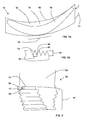
Figure 1 a is a top view of an exemplary blade comprising a ultrasonic wave scattering feature; -
Figure 1b is an expanded view of a portion of the ultrasonic wave scattering feature ofFig 1 a; -
Figure 2 is side view of the exemplary blade ofFig. 1 a; and -
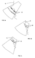
Figures 3a,b,c show the effect of an ultrasonic wave scattering feature on ultrasonic pulse reflection. - Exemplary embodiments of the present disclosure are now described with references to the drawings, wherein like reference numerals are used to refer to like elements throughout. In the following description, for purposes of explanation, numerous specific details are set forth to provide a thorough understanding of the disclosure. However, the present disclosure may be practiced without these specific details, and is not limited to the exemplary embodiments disclosed herein.
- An exemplary embodiment shown in
Fig. 1 a comprises aturbine blade 10 with aroot section 11 for engaging with a rotor (not shown). In this context, engaging means that theroot section 11 is configured to fixingly attach to a rotor. This may be by any known means includingsuitable root section 11 configurations that are adapted to retain theroot section 11 in a rotor. Such configurations include a fir tree, T-root or a pin-root arrangement. - The
root section 11 further includes aplatform 12 having atop surface 14, and anedge 16 that forms an outer boundary of thetop surface 14. That is, in the installed position in a rotor, theedge 16 defines the axial and circumferential limits of theplatform 12. In the exemplary embodiment, theedge 16 includes anedge surface 17. Such anedge surface 17 is a surface that is generally orthogonal to thetop surface 14 of theplatform 12 and further circumscribes theplatform 12. - As shown in
Fig. 1a , at least a portion of theedge surface 17 comprises an ultrasonicwave scattering feature 20 adapted to alter a reflection path of an ultrasonic pulse wave. While it is recognised that standard features ofroot section 11 may be able to scatter ultrasonic waves to a limited degree, within this specification an ultrasonicwave scattering feature 20 differentiates itself from such as feature by having the sole function of ultrasonic wave scattering. For this reason, curves of a fir tree, which have the function of fixing theroot section 11 into a rotor,edges 16 andedges surfaces 17 having the function of defining the shape of aplatform 12 and further providing sealing and or mating services with rotor grooves and/ or adjacently fitted turbine blades, and other such features that define the turbine blades structural, functional and fluidal performance are not ultrasonic wave scattering features 20. - In an exemplary embodiment shown in
Fig. 1 a and in expanded viewFig. 1b , the ultrasonic wave scattering features 20 comprises a plurality ofserrated teeth 22 arranged to formridges 24 interspaced withvalleys 26. In an exemplary embodiment, theridges 24 are aligned so as to extend across theedge surface 17 thereby aligningridges 24 andvalleys 26 essentially perpendicular to thetop surface 14. In an alternate not show exemplary embodiment,ridges 24 andvalleys 26 are aligned along the edge surface so as to be essentially parallel to thetop surface 14. In further exemplary embodiments,ridges 24 andvalleys 26 are aligned between these two extremes. In a yet further exemplary embodiment,ridges 24 andvalleys 26 are not linear but curved so may comprise characteristics of both extremes. - In an exemplary embodiment shown in
Fig. 1b , at least some of the plurality ofserrated teeth 22 has aheight 28 perpendicular to theedge surface 17, as measured between aridge 24 and anadjacent valley 26, in a range of 0.4 mm to 2.0 mm. In a further exemplary embodiment, theheight 28 is of 0.5 mm. In this context the direction ofheight 28 in the region of theridge 24 is based on the plain theedge surface 17 would form free of surface imperfections and wave scattering features 20. - In an exemplary embodiment shown in
Fig. 1b , at least one of the plurality ofserrated teeth 22 has apitch 30 in the range of 0.5 mm to 2.0mm. In a further exemplary embodiment, at least one of the plurality ofserrated teeth 22 has a pitch of 1 mm wherein pitch is defined as the distance, in the horizontal plain, between eachridges 24 andadjacent valley 26. - In an exemplary embodiment the
turbine blade 10 is configured as a multi-stage steam turbine blade and may further be configured as a last stage steam turbine blade. -
Fig. 2 shows an additional perspective view of the turbine blade ofFigs 1 a and 1 b. -
Fig, 3 a,b,c show the effect of an ultrasonicwave scattering feature 20 onultrasonic pulse echo 32 of standard blade root features shown against aroot outline 18. - In the example provided in
Fig. 3a , theroot section 11 does not include any ultrasonic wave scattering features, and therefore can be considered the base case. As can be seen fromFig. 3a , a strongultrasonic pulse echo 32 occurs in a region of theedge surface 17. - In the example shown in
Fig. 3b , theedge surface 17 includes ultrasonic wave scattering features 20 shown inFigs. 1a, b and Fig.2 , having a height of 0.5 mm. In comparison withFig. 3a , theedge surface 17 shows significantly less measuredultrasonic pulse echo 32. - In the example shown in
Fig. 3c , the height of the ultrasonicwave scattering feature 20 ofFig. 3b is increased to 2.0 mm. In comparison toFig. 3b , theedge surface 17 shows a further reduction inultrasonic pulse echo 32 to the point of almost noultrasonic pulse echo 32. For the given example, it would be possible to include wave scattering features 20 having a height greater than 2.0mm up to the point where the wave scattering features 20 affect the characteristics of the blade, for example by influencing inter blade platform sealing. The upper limit is, therefore, depending on blade configurationally constraints unrelated to testing limitations. - As a result of the reduced echo of standard blade features, defects in the region of the ultrasonic
wave scattering feature 20 have less chance to be potentially hidden. - The optimum arrangement and configuration of the wave scattering features 20 is dependent on the configuration of the
root section 11 in regard the location of curved and edged regions and their capability to reflect ultrasonic waves and as a result mask the reflection of defects. The presently disclosed embodiments are therefore considered in all respects to be illustrative and not restricted. The scope of the disclosure is indicated by the appended claims rather that the foregoing description and all changes that come within the meaning and range and equivalences thereof are intended to be embraced therein. -
- 10
- turbine blade
- 11
- root section
- 12
- platform
- 14
- top surface
- 16
- edge
- 17
- edge surface
- 18
- root outline
- 19
- airfoil
- 20
- ultrasonic wave scattering feature
- 22
- serrated tooth
- 24
- ridge
- 26
- valley
- 28
- height
- 30
- pitch
- 32
- ultrasonic pulse echo
Claims (9)
- A turbine blade (10) comprising:a root section (11), for engaging with a rotor, having a platform (12), with:a top surface (14), andan edge (16), forming an outer boundary of the top surface (14), having an edge surface (17); andan airfoil (19) extending from the top surface (14),characterised by at least a portion of the edge surface (17) including an ultrasonic wave scattering feature (20) comprising surface irregularities adapted to alter a reflection path of an ultrasonic pulse wave.
- The turbine blade (10) of claim 1 wherein the ultrasonic wave scattering feature (20) comprises a plurality of serrated teeth (22) that are arranged to form a plurality of ridges (24) each interspaced with a valley (26).
- The turbine blade (10) of claim 2 wherein at least one of the plurality of serrated teeth (22) has a height (28) perpendicular to the edge surface (17) extending between the ridge (24) and an adjacent valley (26), in a range 0.4 mm to 2.0 mm.
- The turbine blade of claim 2 wherein at least one of the plurality of serrated teeth (22) has a height (28) perpendicular to the edge surface (17) extending between the ridge (24) and an adjacent valley (26) of 0.5 mm.
- The turbine blade (10) of claim 2 wherein at least one of the plurality of serrated teeth (22) has a pitch (30) in a range of 0.5 mm to 2.0mm.
- The turbine blade (10) of claim 2 wherein at least one of the plurality of serrated teeth (22) has a pitch of 1 mm.
- The turbine blade (10) of any one of claims 2 to 6 wherein each of the ridges (24) are aligned so as to extend across the edge surface (17).
- The turbine blade (10) of any one of claims 1 to 7 configured as a multi-stage steam turbine blade.
- The turbine blade (10) of claim 8 configured as a last stage steam turbine blade.
Priority Applications (5)
| Application Number | Priority Date | Filing Date | Title |
|---|---|---|---|
| EP15183454.6A EP3139004B1 (en) | 2015-09-02 | 2015-09-02 | Turbine blade with ultrasonic wave scattering feature |
| PCT/EP2016/069501 WO2017036797A1 (en) | 2015-09-02 | 2016-08-17 | Turbine blade with ultrasonic wave scattering feature |
| JP2018511148A JP2018532062A (en) | 2015-09-02 | 2016-08-17 | Turbine blade with ultrasonic scattering features |
| US15/756,802 US10648950B2 (en) | 2015-09-02 | 2016-08-17 | Turbine blade with ultrasonic wave scattering feature |
| CN201680051001.6A CN107923252B (en) | 2015-09-02 | 2016-08-17 | Turbine blade with ultrasonic scattering features |
Applications Claiming Priority (1)
| Application Number | Priority Date | Filing Date | Title |
|---|---|---|---|
| EP15183454.6A EP3139004B1 (en) | 2015-09-02 | 2015-09-02 | Turbine blade with ultrasonic wave scattering feature |
Publications (2)
| Publication Number | Publication Date |
|---|---|
| EP3139004A1 true EP3139004A1 (en) | 2017-03-08 |
| EP3139004B1 EP3139004B1 (en) | 2020-07-29 |
Family
ID=54056105
Family Applications (1)
| Application Number | Title | Priority Date | Filing Date |
|---|---|---|---|
| EP15183454.6A Active EP3139004B1 (en) | 2015-09-02 | 2015-09-02 | Turbine blade with ultrasonic wave scattering feature |
Country Status (5)
| Country | Link |
|---|---|
| US (1) | US10648950B2 (en) |
| EP (1) | EP3139004B1 (en) |
| JP (1) | JP2018532062A (en) |
| CN (1) | CN107923252B (en) |
| WO (1) | WO2017036797A1 (en) |
Cited By (1)
| Publication number | Priority date | Publication date | Assignee | Title |
|---|---|---|---|---|
| CN112236673A (en) * | 2018-05-31 | 2021-01-15 | 劳斯莱斯股份有限公司 | Composite material fan blade root |
Families Citing this family (2)
| Publication number | Priority date | Publication date | Assignee | Title |
|---|---|---|---|---|
| KR102085689B1 (en) * | 2018-08-09 | 2020-04-23 | 주식회사 파워인스 | The carrying apparatus with ultra-sonic inspection device for fir type turbine blade root |
| DE102020201671A1 (en) * | 2020-02-11 | 2021-08-12 | Siemens Aktiengesellschaft | Method for non-destructive crack testing of surfaces of rotor blade receiving grooves and ultrasonic device |
Citations (6)
| Publication number | Priority date | Publication date | Assignee | Title |
|---|---|---|---|---|
| SE151575C1 (en) * | ||||
| GB836030A (en) * | 1955-10-31 | 1960-06-01 | Maschf Augsburg Nuernberg Ag | Improvements in or relating to a turbine blade and rotor assembly |
| US3299696A (en) * | 1961-11-09 | 1967-01-24 | Iii Ben Wade Oakes Dickinson | Apparatus for generating, directing and receiving ultrasonic wave trains |
| JPH10239287A (en) * | 1997-02-26 | 1998-09-11 | Hitachi Ltd | Ultrasonic flaw detector for turbine rotor blade implant |
| DE102006005056A1 (en) * | 2005-02-04 | 2006-08-10 | Mitsubishi Heavy Industries, Ltd. | Blade body |
| US20090165317A1 (en) * | 2007-12-27 | 2009-07-02 | Francis Howard Little | Method and system for integrating ultrasound inspection (ut) with a coordinate measuring machine (cmm) |
Family Cites Families (3)
| Publication number | Priority date | Publication date | Assignee | Title |
|---|---|---|---|---|
| EP2770165A1 (en) * | 2013-02-20 | 2014-08-27 | Siemens Aktiengesellschaft | Riffled seal, turbomachine with riffled seal and method of manufacturing thereof |
| EP2959114A1 (en) * | 2013-02-20 | 2015-12-30 | Siemens Aktiengesellschaft | Riffled seal for a turbomachine, turbomachine and method of manufacturing a riffled seal for a turbomachine |
| CN103698399B (en) * | 2013-12-19 | 2016-06-29 | 国家电网公司 | A kind of turbine blade fir-tree type root ultra sonic imaging detection method |
-
2015
- 2015-09-02 EP EP15183454.6A patent/EP3139004B1/en active Active
-
2016
- 2016-08-17 US US15/756,802 patent/US10648950B2/en not_active Expired - Fee Related
- 2016-08-17 JP JP2018511148A patent/JP2018532062A/en active Pending
- 2016-08-17 WO PCT/EP2016/069501 patent/WO2017036797A1/en not_active Ceased
- 2016-08-17 CN CN201680051001.6A patent/CN107923252B/en not_active Expired - Fee Related
Patent Citations (6)
| Publication number | Priority date | Publication date | Assignee | Title |
|---|---|---|---|---|
| SE151575C1 (en) * | ||||
| GB836030A (en) * | 1955-10-31 | 1960-06-01 | Maschf Augsburg Nuernberg Ag | Improvements in or relating to a turbine blade and rotor assembly |
| US3299696A (en) * | 1961-11-09 | 1967-01-24 | Iii Ben Wade Oakes Dickinson | Apparatus for generating, directing and receiving ultrasonic wave trains |
| JPH10239287A (en) * | 1997-02-26 | 1998-09-11 | Hitachi Ltd | Ultrasonic flaw detector for turbine rotor blade implant |
| DE102006005056A1 (en) * | 2005-02-04 | 2006-08-10 | Mitsubishi Heavy Industries, Ltd. | Blade body |
| US20090165317A1 (en) * | 2007-12-27 | 2009-07-02 | Francis Howard Little | Method and system for integrating ultrasound inspection (ut) with a coordinate measuring machine (cmm) |
Cited By (2)
| Publication number | Priority date | Publication date | Assignee | Title |
|---|---|---|---|---|
| CN112236673A (en) * | 2018-05-31 | 2021-01-15 | 劳斯莱斯股份有限公司 | Composite material fan blade root |
| US11867087B2 (en) | 2018-05-31 | 2024-01-09 | Rolls-Royce Plc | Composite fan blade root |
Also Published As
| Publication number | Publication date |
|---|---|
| CN107923252A (en) | 2018-04-17 |
| US10648950B2 (en) | 2020-05-12 |
| WO2017036797A1 (en) | 2017-03-09 |
| CN107923252B (en) | 2020-10-27 |
| EP3139004B1 (en) | 2020-07-29 |
| US20180245473A1 (en) | 2018-08-30 |
| JP2018532062A (en) | 2018-11-01 |
Similar Documents
| Publication | Publication Date | Title |
|---|---|---|
| CN103698399B (en) | A kind of turbine blade fir-tree type root ultra sonic imaging detection method | |
| US7428842B2 (en) | Phased array ultrasonic testing system and methods of examination and modeling employing the same | |
| EP1751535B1 (en) | Method and device for determining defects in a turbine blade with an ultrasonic phased array | |
| JP6300225B2 (en) | Turbine blade inspection device and inspection method thereof | |
| CN104535648B (en) | A kind of turbine blade ultrasonic guided wave detecting method | |
| US10648950B2 (en) | Turbine blade with ultrasonic wave scattering feature | |
| CN105445374A (en) | Ultrasonic phased array detection method for fir type blade roots of nuclear main turbine | |
| Yang et al. | Using phased array ultrasonic technique for the inspection of straddle mount-type low-pressure turbine disc | |
| CN102156166A (en) | Ultrasonic climbing wave detection method for laterally assembled fir tree blade root of steam turbine and special probe for method | |
| CA2595886C (en) | Method and device for determining defects on a constructional element of a turbine | |
| US7775111B2 (en) | Method of analyzing ultrasonic inspection data from turbine wheel finger dovetails to identify the presence of cracks on the finger ledges | |
| JP2004245834A (en) | Method for inspecting finger dovetail of wheels and buckets for cracks | |
| WO2009000793A1 (en) | Method for the non-destructive inspection of rotor blades of a steam turbine and inspection device for being used in said method | |
| JP2009204368A (en) | Blade groove inspection method of turbine rotor | |
| CN103698405A (en) | Ultrasonic imaging detection phased array transduction device for blade fir-type root of turbine | |
| US20180095006A1 (en) | Method for non-destructive material testing | |
| JP5414559B2 (en) | Ultrasonic inspection method | |
| CN203798776U (en) | Turbine blade fir tree-type root ultrasonic imaging detection phased array transduction device | |
| US20250052170A1 (en) | System and method for ultrasonic phased array inspection of integral shroud drum stage t-root blades | |
| CN114858920A (en) | Ultrasonic-based generator end tooth root crack identification method | |
| KR20130022916A (en) | Method for detecting crack in the turbin blade rootfinger | |
| JP2003294716A (en) | Turbine inspection method | |
| JP4049985B2 (en) | Ultrasonic flaw detection apparatus and method | |
| US20210301672A1 (en) | Composite fan blade root | |
| Ciorau et al. | How Reliable is Your Call? OPG Phased Array Ultrasonic Inspection Experience on Siemens-Parson Turbine Blade Roots 2001-2007 |
Legal Events
| Date | Code | Title | Description |
|---|---|---|---|
| PUAI | Public reference made under article 153(3) epc to a published international application that has entered the european phase |
Free format text: ORIGINAL CODE: 0009012 |
|
| STAA | Information on the status of an ep patent application or granted ep patent |
Free format text: STATUS: THE APPLICATION HAS BEEN PUBLISHED |
|
| AK | Designated contracting states |
Kind code of ref document: A1 Designated state(s): AL AT BE BG CH CY CZ DE DK EE ES FI FR GB GR HR HU IE IS IT LI LT LU LV MC MK MT NL NO PL PT RO RS SE SI SK SM TR |
|
| AX | Request for extension of the european patent |
Extension state: BA ME |
|
| STAA | Information on the status of an ep patent application or granted ep patent |
Free format text: STATUS: REQUEST FOR EXAMINATION WAS MADE |
|
| 17P | Request for examination filed |
Effective date: 20170908 |
|
| RBV | Designated contracting states (corrected) |
Designated state(s): AL AT BE BG CH CY CZ DE DK EE ES FI FR GB GR HR HU IE IS IT LI LT LU LV MC MK MT NL NO PL PT RO RS SE SI SK SM TR |
|
| REG | Reference to a national code |
Ref country code: DE Ref legal event code: R079 Ref document number: 602015056422 Country of ref document: DE Free format text: PREVIOUS MAIN CLASS: F01D0005300000 Ipc: G01N0029040000 |
|
| GRAP | Despatch of communication of intention to grant a patent |
Free format text: ORIGINAL CODE: EPIDOSNIGR1 |
|
| STAA | Information on the status of an ep patent application or granted ep patent |
Free format text: STATUS: GRANT OF PATENT IS INTENDED |
|
| RIC1 | Information provided on ipc code assigned before grant |
Ipc: F01D 5/30 20060101ALI20200115BHEP Ipc: G01N 29/22 20060101ALI20200115BHEP Ipc: F01D 5/26 20060101ALI20200115BHEP Ipc: G01N 29/04 20060101AFI20200115BHEP |
|
| INTG | Intention to grant announced |
Effective date: 20200219 |
|
| GRAS | Grant fee paid |
Free format text: ORIGINAL CODE: EPIDOSNIGR3 |
|
| GRAA | (expected) grant |
Free format text: ORIGINAL CODE: 0009210 |
|
| STAA | Information on the status of an ep patent application or granted ep patent |
Free format text: STATUS: THE PATENT HAS BEEN GRANTED |
|
| AK | Designated contracting states |
Kind code of ref document: B1 Designated state(s): AL AT BE BG CH CY CZ DE DK EE ES FI FR GB GR HR HU IE IS IT LI LT LU LV MC MK MT NL NO PL PT RO RS SE SI SK SM TR |
|
| REG | Reference to a national code |
Ref country code: CH Ref legal event code: EP |
|
| REG | Reference to a national code |
Ref country code: AT Ref legal event code: REF Ref document number: 1296380 Country of ref document: AT Kind code of ref document: T Effective date: 20200815 |
|
| REG | Reference to a national code |
Ref country code: IE Ref legal event code: FG4D |
|
| REG | Reference to a national code |
Ref country code: DE Ref legal event code: R096 Ref document number: 602015056422 Country of ref document: DE |
|
| REG | Reference to a national code |
Ref country code: LT Ref legal event code: MG4D |
|
| REG | Reference to a national code |
Ref country code: NL Ref legal event code: MP Effective date: 20200729 |
|
| REG | Reference to a national code |
Ref country code: AT Ref legal event code: MK05 Ref document number: 1296380 Country of ref document: AT Kind code of ref document: T Effective date: 20200729 |
|
| PG25 | Lapsed in a contracting state [announced via postgrant information from national office to epo] |
Ref country code: GR Free format text: LAPSE BECAUSE OF FAILURE TO SUBMIT A TRANSLATION OF THE DESCRIPTION OR TO PAY THE FEE WITHIN THE PRESCRIBED TIME-LIMIT Effective date: 20201030 Ref country code: LT Free format text: LAPSE BECAUSE OF FAILURE TO SUBMIT A TRANSLATION OF THE DESCRIPTION OR TO PAY THE FEE WITHIN THE PRESCRIBED TIME-LIMIT Effective date: 20200729 Ref country code: HR Free format text: LAPSE BECAUSE OF FAILURE TO SUBMIT A TRANSLATION OF THE DESCRIPTION OR TO PAY THE FEE WITHIN THE PRESCRIBED TIME-LIMIT Effective date: 20200729 Ref country code: SE Free format text: LAPSE BECAUSE OF FAILURE TO SUBMIT A TRANSLATION OF THE DESCRIPTION OR TO PAY THE FEE WITHIN THE PRESCRIBED TIME-LIMIT Effective date: 20200729 Ref country code: PT Free format text: LAPSE BECAUSE OF FAILURE TO SUBMIT A TRANSLATION OF THE DESCRIPTION OR TO PAY THE FEE WITHIN THE PRESCRIBED TIME-LIMIT Effective date: 20201130 Ref country code: FI Free format text: LAPSE BECAUSE OF FAILURE TO SUBMIT A TRANSLATION OF THE DESCRIPTION OR TO PAY THE FEE WITHIN THE PRESCRIBED TIME-LIMIT Effective date: 20200729 Ref country code: NO Free format text: LAPSE BECAUSE OF FAILURE TO SUBMIT A TRANSLATION OF THE DESCRIPTION OR TO PAY THE FEE WITHIN THE PRESCRIBED TIME-LIMIT Effective date: 20201029 Ref country code: BG Free format text: LAPSE BECAUSE OF FAILURE TO SUBMIT A TRANSLATION OF THE DESCRIPTION OR TO PAY THE FEE WITHIN THE PRESCRIBED TIME-LIMIT Effective date: 20201029 Ref country code: AT Free format text: LAPSE BECAUSE OF FAILURE TO SUBMIT A TRANSLATION OF THE DESCRIPTION OR TO PAY THE FEE WITHIN THE PRESCRIBED TIME-LIMIT Effective date: 20200729 Ref country code: ES Free format text: LAPSE BECAUSE OF FAILURE TO SUBMIT A TRANSLATION OF THE DESCRIPTION OR TO PAY THE FEE WITHIN THE PRESCRIBED TIME-LIMIT Effective date: 20200729 |
|
| PG25 | Lapsed in a contracting state [announced via postgrant information from national office to epo] |
Ref country code: PL Free format text: LAPSE BECAUSE OF FAILURE TO SUBMIT A TRANSLATION OF THE DESCRIPTION OR TO PAY THE FEE WITHIN THE PRESCRIBED TIME-LIMIT Effective date: 20200729 Ref country code: LV Free format text: LAPSE BECAUSE OF FAILURE TO SUBMIT A TRANSLATION OF THE DESCRIPTION OR TO PAY THE FEE WITHIN THE PRESCRIBED TIME-LIMIT Effective date: 20200729 Ref country code: RS Free format text: LAPSE BECAUSE OF FAILURE TO SUBMIT A TRANSLATION OF THE DESCRIPTION OR TO PAY THE FEE WITHIN THE PRESCRIBED TIME-LIMIT Effective date: 20200729 Ref country code: IS Free format text: LAPSE BECAUSE OF FAILURE TO SUBMIT A TRANSLATION OF THE DESCRIPTION OR TO PAY THE FEE WITHIN THE PRESCRIBED TIME-LIMIT Effective date: 20201129 |
|
| PG25 | Lapsed in a contracting state [announced via postgrant information from national office to epo] |
Ref country code: NL Free format text: LAPSE BECAUSE OF FAILURE TO SUBMIT A TRANSLATION OF THE DESCRIPTION OR TO PAY THE FEE WITHIN THE PRESCRIBED TIME-LIMIT Effective date: 20200729 |
|
| REG | Reference to a national code |
Ref country code: DE Ref legal event code: R119 Ref document number: 602015056422 Country of ref document: DE |
|
| PG25 | Lapsed in a contracting state [announced via postgrant information from national office to epo] |
Ref country code: MC Free format text: LAPSE BECAUSE OF FAILURE TO SUBMIT A TRANSLATION OF THE DESCRIPTION OR TO PAY THE FEE WITHIN THE PRESCRIBED TIME-LIMIT Effective date: 20200729 Ref country code: EE Free format text: LAPSE BECAUSE OF FAILURE TO SUBMIT A TRANSLATION OF THE DESCRIPTION OR TO PAY THE FEE WITHIN THE PRESCRIBED TIME-LIMIT Effective date: 20200729 Ref country code: SM Free format text: LAPSE BECAUSE OF FAILURE TO SUBMIT A TRANSLATION OF THE DESCRIPTION OR TO PAY THE FEE WITHIN THE PRESCRIBED TIME-LIMIT Effective date: 20200729 Ref country code: RO Free format text: LAPSE BECAUSE OF FAILURE TO SUBMIT A TRANSLATION OF THE DESCRIPTION OR TO PAY THE FEE WITHIN THE PRESCRIBED TIME-LIMIT Effective date: 20200729 Ref country code: IT Free format text: LAPSE BECAUSE OF FAILURE TO SUBMIT A TRANSLATION OF THE DESCRIPTION OR TO PAY THE FEE WITHIN THE PRESCRIBED TIME-LIMIT Effective date: 20200729 Ref country code: DK Free format text: LAPSE BECAUSE OF FAILURE TO SUBMIT A TRANSLATION OF THE DESCRIPTION OR TO PAY THE FEE WITHIN THE PRESCRIBED TIME-LIMIT Effective date: 20200729 Ref country code: CZ Free format text: LAPSE BECAUSE OF FAILURE TO SUBMIT A TRANSLATION OF THE DESCRIPTION OR TO PAY THE FEE WITHIN THE PRESCRIBED TIME-LIMIT Effective date: 20200729 |
|
| REG | Reference to a national code |
Ref country code: CH Ref legal event code: PL |
|
| PG25 | Lapsed in a contracting state [announced via postgrant information from national office to epo] |
Ref country code: AL Free format text: LAPSE BECAUSE OF FAILURE TO SUBMIT A TRANSLATION OF THE DESCRIPTION OR TO PAY THE FEE WITHIN THE PRESCRIBED TIME-LIMIT Effective date: 20200729 |
|
| PLBE | No opposition filed within time limit |
Free format text: ORIGINAL CODE: 0009261 |
|
| STAA | Information on the status of an ep patent application or granted ep patent |
Free format text: STATUS: NO OPPOSITION FILED WITHIN TIME LIMIT |
|
| REG | Reference to a national code |
Ref country code: BE Ref legal event code: MM Effective date: 20200930 |
|
| GBPC | Gb: european patent ceased through non-payment of renewal fee |
Effective date: 20201029 |
|
| PG25 | Lapsed in a contracting state [announced via postgrant information from national office to epo] |
Ref country code: LU Free format text: LAPSE BECAUSE OF NON-PAYMENT OF DUE FEES Effective date: 20200902 Ref country code: SK Free format text: LAPSE BECAUSE OF FAILURE TO SUBMIT A TRANSLATION OF THE DESCRIPTION OR TO PAY THE FEE WITHIN THE PRESCRIBED TIME-LIMIT Effective date: 20200729 |
|
| 26N | No opposition filed |
Effective date: 20210430 |
|
| PG25 | Lapsed in a contracting state [announced via postgrant information from national office to epo] |
Ref country code: DE Free format text: LAPSE BECAUSE OF NON-PAYMENT OF DUE FEES Effective date: 20210401 Ref country code: FR Free format text: LAPSE BECAUSE OF NON-PAYMENT OF DUE FEES Effective date: 20200929 |
|
| PG25 | Lapsed in a contracting state [announced via postgrant information from national office to epo] |
Ref country code: SI Free format text: LAPSE BECAUSE OF FAILURE TO SUBMIT A TRANSLATION OF THE DESCRIPTION OR TO PAY THE FEE WITHIN THE PRESCRIBED TIME-LIMIT Effective date: 20200729 Ref country code: LI Free format text: LAPSE BECAUSE OF NON-PAYMENT OF DUE FEES Effective date: 20200930 Ref country code: IE Free format text: LAPSE BECAUSE OF NON-PAYMENT OF DUE FEES Effective date: 20200902 Ref country code: GB Free format text: LAPSE BECAUSE OF NON-PAYMENT OF DUE FEES Effective date: 20201029 Ref country code: CH Free format text: LAPSE BECAUSE OF NON-PAYMENT OF DUE FEES Effective date: 20200930 Ref country code: BE Free format text: LAPSE BECAUSE OF NON-PAYMENT OF DUE FEES Effective date: 20200930 |
|
| PG25 | Lapsed in a contracting state [announced via postgrant information from national office to epo] |
Ref country code: TR Free format text: LAPSE BECAUSE OF FAILURE TO SUBMIT A TRANSLATION OF THE DESCRIPTION OR TO PAY THE FEE WITHIN THE PRESCRIBED TIME-LIMIT Effective date: 20200729 Ref country code: MT Free format text: LAPSE BECAUSE OF FAILURE TO SUBMIT A TRANSLATION OF THE DESCRIPTION OR TO PAY THE FEE WITHIN THE PRESCRIBED TIME-LIMIT Effective date: 20200729 Ref country code: CY Free format text: LAPSE BECAUSE OF FAILURE TO SUBMIT A TRANSLATION OF THE DESCRIPTION OR TO PAY THE FEE WITHIN THE PRESCRIBED TIME-LIMIT Effective date: 20200729 |
|
| PG25 | Lapsed in a contracting state [announced via postgrant information from national office to epo] |
Ref country code: MK Free format text: LAPSE BECAUSE OF FAILURE TO SUBMIT A TRANSLATION OF THE DESCRIPTION OR TO PAY THE FEE WITHIN THE PRESCRIBED TIME-LIMIT Effective date: 20200729 |