EP3139003A1 - Damper pin for turbine blades and corresponding turbine engine - Google Patents
Damper pin for turbine blades and corresponding turbine engine Download PDFInfo
- Publication number
- EP3139003A1 EP3139003A1 EP16186535.7A EP16186535A EP3139003A1 EP 3139003 A1 EP3139003 A1 EP 3139003A1 EP 16186535 A EP16186535 A EP 16186535A EP 3139003 A1 EP3139003 A1 EP 3139003A1
- Authority
- EP
- European Patent Office
- Prior art keywords
- elongated body
- end portion
- damper pin
- slot
- turbine
- Prior art date
- Legal status (The legal status is an assumption and is not a legal conclusion. Google has not performed a legal analysis and makes no representation as to the accuracy of the status listed.)
- Granted
Links
- 238000013016 damping Methods 0.000 claims abstract description 7
- 239000011248 coating agent Substances 0.000 claims description 6
- 238000000576 coating method Methods 0.000 claims description 6
- 230000000295 complement effect Effects 0.000 claims description 5
- 239000007789 gas Substances 0.000 description 13
- 239000000567 combustion gas Substances 0.000 description 7
- 239000012530 fluid Substances 0.000 description 6
- 230000008901 benefit Effects 0.000 description 3
- 238000012986 modification Methods 0.000 description 3
- 230000004048 modification Effects 0.000 description 3
- 238000006243 chemical reaction Methods 0.000 description 2
- 238000013461 design Methods 0.000 description 2
- 238000010586 diagram Methods 0.000 description 2
- 230000006870 function Effects 0.000 description 2
- 238000011144 upstream manufacturing Methods 0.000 description 2
- 238000002485 combustion reaction Methods 0.000 description 1
- 230000005611 electricity Effects 0.000 description 1
- 230000005284 excitation Effects 0.000 description 1
- 239000000446 fuel Substances 0.000 description 1
- 230000003116 impacting effect Effects 0.000 description 1
- 239000002184 metal Substances 0.000 description 1
- 238000000034 method Methods 0.000 description 1
- 230000037361 pathway Effects 0.000 description 1
- 230000004044 response Effects 0.000 description 1
- 238000012552 review Methods 0.000 description 1
- 230000035882 stress Effects 0.000 description 1
- 238000012360 testing method Methods 0.000 description 1
- 230000008646 thermal stress Effects 0.000 description 1
- 230000007704 transition Effects 0.000 description 1
Images


Classifications
-
- F—MECHANICAL ENGINEERING; LIGHTING; HEATING; WEAPONS; BLASTING
- F01—MACHINES OR ENGINES IN GENERAL; ENGINE PLANTS IN GENERAL; STEAM ENGINES
- F01D—NON-POSITIVE DISPLACEMENT MACHINES OR ENGINES, e.g. STEAM TURBINES
- F01D5/00—Blades; Blade-carrying members; Heating, heat-insulating, cooling or antivibration means on the blades or the members
- F01D5/12—Blades
- F01D5/22—Blade-to-blade connections, e.g. for damping vibrations
-
- F—MECHANICAL ENGINEERING; LIGHTING; HEATING; WEAPONS; BLASTING
- F01—MACHINES OR ENGINES IN GENERAL; ENGINE PLANTS IN GENERAL; STEAM ENGINES
- F01D—NON-POSITIVE DISPLACEMENT MACHINES OR ENGINES, e.g. STEAM TURBINES
- F01D5/00—Blades; Blade-carrying members; Heating, heat-insulating, cooling or antivibration means on the blades or the members
- F01D5/12—Blades
- F01D5/26—Antivibration means not restricted to blade form or construction or to blade-to-blade connections or to the use of particular materials
-
- F—MECHANICAL ENGINEERING; LIGHTING; HEATING; WEAPONS; BLASTING
- F05—INDEXING SCHEMES RELATING TO ENGINES OR PUMPS IN VARIOUS SUBCLASSES OF CLASSES F01-F04
- F05D—INDEXING SCHEME FOR ASPECTS RELATING TO NON-POSITIVE-DISPLACEMENT MACHINES OR ENGINES, GAS-TURBINES OR JET-PROPULSION PLANTS
- F05D2220/00—Application
- F05D2220/30—Application in turbines
- F05D2220/32—Application in turbines in gas turbines
-
- F—MECHANICAL ENGINEERING; LIGHTING; HEATING; WEAPONS; BLASTING
- F05—INDEXING SCHEMES RELATING TO ENGINES OR PUMPS IN VARIOUS SUBCLASSES OF CLASSES F01-F04
- F05D—INDEXING SCHEME FOR ASPECTS RELATING TO NON-POSITIVE-DISPLACEMENT MACHINES OR ENGINES, GAS-TURBINES OR JET-PROPULSION PLANTS
- F05D2250/00—Geometry
- F05D2250/30—Arrangement of components
- F05D2250/31—Arrangement of components according to the direction of their main axis or their axis of rotation
- F05D2250/312—Arrangement of components according to the direction of their main axis or their axis of rotation the axes being parallel to each other
-
- F—MECHANICAL ENGINEERING; LIGHTING; HEATING; WEAPONS; BLASTING
- F05—INDEXING SCHEMES RELATING TO ENGINES OR PUMPS IN VARIOUS SUBCLASSES OF CLASSES F01-F04
- F05D—INDEXING SCHEME FOR ASPECTS RELATING TO NON-POSITIVE-DISPLACEMENT MACHINES OR ENGINES, GAS-TURBINES OR JET-PROPULSION PLANTS
- F05D2250/00—Geometry
- F05D2250/40—Movement of components
- F05D2250/41—Movement of components with one degree of freedom
-
- Y—GENERAL TAGGING OF NEW TECHNOLOGICAL DEVELOPMENTS; GENERAL TAGGING OF CROSS-SECTIONAL TECHNOLOGIES SPANNING OVER SEVERAL SECTIONS OF THE IPC; TECHNICAL SUBJECTS COVERED BY FORMER USPC CROSS-REFERENCE ART COLLECTIONS [XRACs] AND DIGESTS
- Y02—TECHNOLOGIES OR APPLICATIONS FOR MITIGATION OR ADAPTATION AGAINST CLIMATE CHANGE
- Y02T—CLIMATE CHANGE MITIGATION TECHNOLOGIES RELATED TO TRANSPORTATION
- Y02T50/00—Aeronautics or air transport
- Y02T50/60—Efficient propulsion technologies, e.g. for aircraft
Definitions
- the present invention generally relates to a turbine engine having multiple circumferentially aligned turbine blades. More particularly, this invention involves a damper pin for providing vibration damping between adjacent turbine blades of a turbine engine.
- a turbine blade also known as a turbine bucket or turbine rotor blade, converts energy from a flowing fluid such as hot combustion gas or steam into mechanical energy by causing a rotor shaft of a turbomachine to rotate. As the turbomachine transitions through various operating modes, the turbine blades are subjected to both mechanical and thermal stresses.
- a turbine blade generally includes an airfoil that extends radially outwardly from a platform, a shank that extends radially inwardly from the platform and a dovetail or mounting portion that extends radially inwardly from the shank.
- the dovetail of each turbine blade is secured within a complementary slot defined in a rotor wheel or disk.
- the rotor wheel is coupled to the rotor shaft.
- vibrations may be introduced into the turbine blades. For example, fluctuations in flow of the hot combustion gases or steam may cause them to vibrate.
- One basic design consideration for turbomachine designers is to avoid or to minimize resonance with natural frequencies of the turbine blades and the dynamic stresses produced by forced response and/or aero-elastic instabilities, thus controlling high cycle fatigue of the turbine blades.
- vibration dampers are typically provided below and/or between the platforms to frictionally dissipate vibratory energy and reduce the corresponding amplitude of vibration during operation.
- the amount of vibrational energy that is removed by the vibration damper is a function of the dynamic weight of the vibration damper and the reaction loads.
- dampers may be largely adequate during typical operations, there is a desire to improve overall damper effectiveness.
- Prior attempts to accomplish damping of vibrations have included round damper pins, sheet metal flat dampers, or complex wedge shaped dampers. Often true damper performance of these types of dampers is not known until the first engine test. However, at that time, the damper pocket geometry in the turbine blades is locked in by hard tooling. Thus, if the damper does not perform as expected, then a potentially expensive tooling rework may be required. Accordingly, there is desire for a damping pin that provides a natural frequency tuning tool for resonant mode excitation avoidance and that enables independent mode tuning options without necessitating changes to the design of an existing turbine blade.
- One embodiment of the present invention is a damper pin for damping adjacent turbine blades coupled to a rotor disk.
- the damper pin a first elongated body having a center portion that is disposed between a first end portion and a second end portion. The first end portion, center portion and second end portion define a generally arcuate top portion of the first elongated body.
- the first elongated body defines a slot that extends axially therethrough.
- the damper pin further includes a second elongated body having a generally arcuate top portion. The second elongated body is at least partially disposed within the slot. The second elongated body is slideably engaged in an axial direction with the first elongated body.
- the turbine engine includes a rotor shaft that extends axially within the turbine engine and a plurality of turbine blades coupled to the rotor shaft.
- the turbine blades extend radially outwardly from the rotor shaft.
- Each turbine blade has an airfoil that extends radially outwardly from a platform.
- the plurality of turbine blades includes a first turbine blade and a second turbine blade that is adjacent to the first turbine blade.
- the first and second turbine blades define a groove therebetween.
- the turbine engine further includes a damper pin disposed within the groove.
- the damper pin includes a irst elongated body having a center portion that is disposed between a first end portion and a second end portion.
- the first end portion, center portion and second end portion define a generally arcuate top portion of the first elongated body.
- the first elongated body defines a slot that extends axially therethrough.
- the damper pin also includes a second elongated body having a generally arcuate top portion. The second elongated body is at least partially disposed within the slot and is slideably engaged in an axial direction with the first elongated body.
- upstream and downstream refer to the relative direction with respect to fluid flow in a fluid pathway.
- upstream refers to the direction from which the fluid flows
- downstream refers to the direction to which the fluid flows.
- radially refers to the relative direction that is substantially perpendicular to an axial centerline of a particular component
- axially refers to the relative direction that is substantially parallel and/or coaxially aligned to an axial centerline of a particular component.
- FIG. 1 illustrates a schematic diagram of one embodiment of a gas turbine 10.
- the gas turbine 10 generally includes an inlet section 12, a compressor section 14 disposed downstream of the inlet section 12, a plurality of combustors (not shown) within a combustor section 16 disposed downstream of the compressor section 14, a turbine section 18 disposed downstream of the combustor section 16 and an exhaust section 20 disposed downstream of the turbine section 18. Additionally, the gas turbine 10 may include one or more shafts 22 coupled between the compressor section 14 and the turbine section 18.
- the turbine section 18 may generally include a rotor shaft 24 having a plurality of rotor disks 26 (one of which is shown) and a plurality of rotor blades 28 extending radially outwardly from and being interconnected to the rotor disk 26. Each rotor disk 26 in turn, may be coupled to a portion of the rotor shaft 24 that extends through the turbine section 18.
- the turbine section 18 further includes an outer casing 30 that circumferentially surrounds the rotor shaft 24 and the rotor blades 28, thereby at least partially defining a hot gas path 32 through the turbine section 18.
- a working fluid such as air flows through the inlet section 12 and into the compressor section 14 where the air is progressively compressed, thus providing pressurized air to the combustors of the combustion section 16.
- the pressurized air is mixed with fuel and burned within each combustor to produce combustion gases 34.
- the combustion gases 34 flow through the hot gas path 32 from the combustor section 16 into the turbine section 18, wherein energy (kinetic and/or thermal) is transferred from the combustion gases 34 to the rotor blades 28, thus causing the rotor shaft 24 to rotate.
- the mechanical rotational energy may then be used to power the compressor section 14 and/or to generate electricity.
- the combustion gases 34 exiting the turbine section 18 may then be exhausted from the gas turbine 10 via the exhaust section 20.
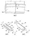
- FIG. 2 illustrates a conventional turbine blade or bucket 28 including an airfoil 36, a platform 38, a shank 40 and a dovetail or mounting portion 42.
- FIG. 3 provides a downstream view of a pair of circumferentially adjacent turbine blades 28(a), 28(b).
- the dovetail 42 is utilized to secure the turbine blade 28 to a periphery of the rotor disk 26 ( FIG. 1 ), as is well understood in the art.
- the platform 38 defines an inward flow boundary for the combustion gases 34 flowing through the hot gas path 32 of the turbine section 18 ( FIG. 1 ).
- a damper pin 44 is located along one axial edge (or slash face) 46 adjacent to (i.e., radially inward of) the turbine blade platform 38. It will be appreciated that a similar damper pin 44 is located between each adjacent pair of turbine blades 28(a), 28(b) ( FIG. 3 ) on the rotor disk 26 ( FIG. 1 ) as apparent from FIG. 3 . In particular embodiments, as shown in FIG. 2 , the damper pin 44 is located in an elongated groove 48 ( FIG. 1 ) that extends along the entire slash face 46 of the turbine blade 28.
- the damper pin 44 serves as a vibration damper. When installed, as shown in FIG. 3 , the damper pin 44 is positioned between the adjacent turbine blades 28(a), 28(b). In operation, the damper pin 44 frictionally dissipates vibratory energy and reduces corresponding amplitude of vibration. The amount of vibrational energy that is removed by the damper pin 44 is a function several factors including but not limited to the dynamic weight of the damper pin 44, the geometry of the damper pin 44 and the reaction loads between the adjacent turbine blades 28(a), 28(b).
- FIG. 4 provides a perspective view of an exemplary damper pin 100 according to one embodiment of the present invention. It is to be understood that damper pin 100 shown in FIG. 4 may be substituted for damper pin 44 as shown in FIGS. 2 and 3 .
- the damper pin 100 includes a first elongated body 102 having a center portion 104 disposed between a first end portion 106 and a second end portion 108.
- the first end portion 106, center portion 104 and the second end portion 108 define a generally arcuate top portion or surface 110 of the first elongated body 102.
- the first elongated body 102 further defines a slot 112 that extends axially through the first elongated body 102.
- the slot 112 extends continuously through the first end portion 106, the center portion 104 and the second end portion 108.
- Damper pin 100 further includes a second elongated body 114 having a generally arcuate top portion or surface 116.
- the slot 112 and the second elongated body 114 are substantially wedge shaped.
- the second elongated body 114 is at least partially disposed within the slot 112.
- the second elongated body 114 is slideably engaged with the first elongated body 102 in an axial direction with respect to centerline 118.
- At least one of the slot 112 of the first elongated body 102 or a contact surface of the second elongated body 114 that is in contact with the slot 112 of the first elongated body 102 is coated with a low-friction wear-resistant coating.
- the top portion 110 of the first elongated body 102 and the top portion 116 of the second elongated body 114 may configured (sized and/or shaped) to contact with a portion of the groove 48 ( FIG. 2 ) formed between adjacent turbine blades 28(a), 28(b) as shown in FIG. 3 .
- first end portion 106 and/or the second end portion 108 of the first elongated body 102 are semi-cylindrical.
- the center portion 104 of the first elongated body 102 may be substantially cylindrical.
- the first end portion 106 and the second end portion 108 may interface with the center portion 104 at shoulders 120, 122 respectfully.
- This configuration creates flat support surfaces 124, 126 (best seen in FIG. 2 ) that are adapted to rest on machined turbine blade platform surfaces or shoulders at opposite ends of the groove 48 formed in the turbine blade slash face 46, thereby providing support for the damper pin 100 while preventing undesirable excessive rotation during machine operation.
- FIG. 5 provides a perspective view of an exemplary damper pin 200 according to another embodiment of the present invention.
- FIG. 6 provides a front view of damper pin 200 as shown in FIG 5 . It is to be understood that damper pin 200 as shown collectively in FIGS. 5 and 6 may be substituted for damper pin 44 as shown in FIGS. 2 and 3 .
- damper pin 200 includes a first elongated body 202 having a center portion 204 disposed between a first end portion 206 and a second end portion 208.
- the first end portion 206, center portion 204 and the second end portion 208 define a generally arcuate top portion or surface 210 of the first elongated body 202.
- FIG. 7 provides a perspective side view of the first elongated body 202 as shown in FIGS. 5 and 6 , according to one embodiment.
- the first elongated body 202 defines a slot 212 that extends axially through the first elongated body 202.
- the slot 212 extends continuously through the first end portion 206, the center portion 204 and the second end portion 208.
- the slot 212 is dovetail shaped. In this manner, the slot 212 may form a dovetail socket or socket of a sliding dovetail joint.
- damper pin 200 further includes a second elongated body 214 having a generally arcuate top portion or surface 216.
- the top portion 210 of the first elongated body 202 and the top portion 216 of the second elongated body 214 may configured (sized and/or shaped) to contact with a portion of the groove 48 ( FIG. 2 ) formed between adjacent turbine blades 28(a), 28(b) as shown in FIG. 3 .
- the second elongated body 214 is at least partially disposed within the slot 212 and is slideably engaged with the first elongated body 202 in an axial direction with respect to centerline 218.
- FIG. 8 provides a perspective side view of the second elongated body 214 as shown in FIGS. 5 and 6 .
- the second elongated body 214 includes a dovetail shaped protrusion 220.
- the dovetail shaped protrusion 220 is substantially complementary with the slot 212.
- At least one of the slot 212 of the first elongated body 202 or a contact surface 222 of the second elongated body 214 that is in contact with the slot 212 of the first elongated body 202 is coated with a low-friction wear-resistant coating.
- the first end portion 206 and/or the second end portion 208 of the first elongated body 202 are semi-cylindrical.
- the center portion 204 of the first elongated body 202 may be substantially cylindrical.
- the first end portion 206 and the second end portion 208 may interface with the center portion 204 at shoulders 224, 226 respectfully.
- This configuration creates flat support surfaces 228, 230 that are adapted to rest on the machined turbine blade platform surfaces or shoulders at opposite ends of the groove 48 ( FIG. 2 ) formed in the turbine blade slash face 46, thereby providing support for the damper pin 200 while preventing undesirable excessive rotation during machine operation.
- a first end portion 232 and/or a second end portion 234 of the second elongated body 214 are semi-cylindrical.
- a center portion 236 of the second elongated body 214 may be substantially cylindrical.
- the first end portion 232 and the second end portion 234 may interface with the center portion 236 at shoulders 238, 240 respectfully.
- This configuration further creates flat support surfaces 242, 244 that are adapted to rest on the machined turbine blade platform surfaces or shoulders at opposite ends of the groove 48 ( FIG. 2 ) formed in the turbine blade slash face 46, thereby providing support for the damper pin 200 while preventing undesirable excessive rotation during machine operation.
- the flat surfaces may be defined generally adjacent to the flat surfaces 228, 230 of the first elongated body 202.
- the various embodiments of the damper pin illustrated and described herein provide various technical benefits over existing damper pin known in the art.
- the multi piece damper pins 100, 200 provided herein allow for tuning the natural frequency of an existing turbine blade system with an additional advantage of not requiring modifications to the turbine blade or more particularly, to the exiting grooves.
- the sliding engagement between the first elongated body 102, 202 and the second elongated body 114, 214 allows for relative movement between the two bodies, thus impacting stiffness in a single direction independent of stiffness in others directions, thus allowing for natural frequency tuning of specific modes that are more sensitive to particular stiffness directions.
Landscapes
- Engineering & Computer Science (AREA)
- Mechanical Engineering (AREA)
- General Engineering & Computer Science (AREA)
- Turbine Rotor Nozzle Sealing (AREA)
Abstract
Description
- The present invention generally relates to a turbine engine having multiple circumferentially aligned turbine blades. More particularly, this invention involves a damper pin for providing vibration damping between adjacent turbine blades of a turbine engine.
- A turbine blade, also known as a turbine bucket or turbine rotor blade, converts energy from a flowing fluid such as hot combustion gas or steam into mechanical energy by causing a rotor shaft of a turbomachine to rotate. As the turbomachine transitions through various operating modes, the turbine blades are subjected to both mechanical and thermal stresses.
- A turbine blade generally includes an airfoil that extends radially outwardly from a platform, a shank that extends radially inwardly from the platform and a dovetail or mounting portion that extends radially inwardly from the shank. The dovetail of each turbine blade is secured within a complementary slot defined in a rotor wheel or disk. The rotor wheel is coupled to the rotor shaft.
- During engine operation, vibrations may be introduced into the turbine blades. For example, fluctuations in flow of the hot combustion gases or steam may cause them to vibrate. One basic design consideration for turbomachine designers is to avoid or to minimize resonance with natural frequencies of the turbine blades and the dynamic stresses produced by forced response and/or aero-elastic instabilities, thus controlling high cycle fatigue of the turbine blades. In order to improve the high cycle fatigue life of a turbine blade, vibration dampers are typically provided below and/or between the platforms to frictionally dissipate vibratory energy and reduce the corresponding amplitude of vibration during operation. The amount of vibrational energy that is removed by the vibration damper is a function of the dynamic weight of the vibration damper and the reaction loads.
- Although known dampers may be largely adequate during typical operations, there is a desire to improve overall damper effectiveness. Prior attempts to accomplish damping of vibrations have included round damper pins, sheet metal flat dampers, or complex wedge shaped dampers. Often true damper performance of these types of dampers is not known until the first engine test. However, at that time, the damper pocket geometry in the turbine blades is locked in by hard tooling. Thus, if the damper does not perform as expected, then a potentially expensive tooling rework may be required. Accordingly, there is desire for a damping pin that provides a natural frequency tuning tool for resonant mode excitation avoidance and that enables independent mode tuning options without necessitating changes to the design of an existing turbine blade.
- Aspects and advantages of the invention are set forth below in the following description, or may be obvious from the description, or may be learned through practice of the invention.
- One embodiment of the present invention is a damper pin for damping adjacent turbine blades coupled to a rotor disk. The damper pin a first elongated body having a center portion that is disposed between a first end portion and a second end portion. The first end portion, center portion and second end portion define a generally arcuate top portion of the first elongated body. The first elongated body defines a slot that extends axially therethrough. The damper pin further includes a second elongated body having a generally arcuate top portion. The second elongated body is at least partially disposed within the slot. The second elongated body is slideably engaged in an axial direction with the first elongated body.
- Another embodiment of the present invention is a turbine engine. The turbine engine includes a rotor shaft that extends axially within the turbine engine and a plurality of turbine blades coupled to the rotor shaft. The turbine blades extend radially outwardly from the rotor shaft. Each turbine blade has an airfoil that extends radially outwardly from a platform. The plurality of turbine blades includes a first turbine blade and a second turbine blade that is adjacent to the first turbine blade. The first and second turbine blades define a groove therebetween. The turbine engine further includes a damper pin disposed within the groove. The damper pin includes a irst elongated body having a center portion that is disposed between a first end portion and a second end portion. The first end portion, center portion and second end portion define a generally arcuate top portion of the first elongated body. The first elongated body defines a slot that extends axially therethrough. The damper pin also includes a second elongated body having a generally arcuate top portion. The second elongated body is at least partially disposed within the slot and is slideably engaged in an axial direction with the first elongated body.
- Those of ordinary skill in the art will better appreciate the features and aspects of such embodiments, and others, upon review of the specification.
- A full and enabling disclosure of the present invention is set forth more particularly in the remainder of the specification, including reference to the accompanying figures, in which:
-
FIG. 1 illustrates a functional diagram of an exemplary gas turbine as may incorporate at least one embodiment of the present invention; -
FIG. 2 is a perspective view of an exemplary turbine blade according to at least one embodiment of the present invention; -
FIG. 3 is a schematic illustration of a damper pin disposed between circumferentially adjacent turbine blades according to at least one embodiment of the present invention; -
FIG. 4 is a perspective view of an exemplary damper pin according to one embodiment of the present invention; -
FIG. 5 is a perspective view of an exemplary damper pin according to one embodiment of the present invention; -
FIG. 6 is a front view of the exemplary damper pin as shown inFIG 5 , according to one embodiment of the present invention; -
FIG. 7 is a perspective side view of a first elongated body portion of the exemplary damper pin as shown inFIG 5 , according to one embodiment of the present invention; and -
FIG. 8 is a perspective side view of a second elongated body portion of the exemplary damper pin as shown inFIG 5 , according to one embodiment of the present invention. - Reference will now be made in detail to present embodiments of the invention, one or more examples of which are illustrated in the accompanying drawings. The detailed description uses numerical and letter designations to refer to features in the drawings. Like or similar designations in the drawings and description have been used to refer to like or similar parts of the invention. As used herein, the terms "first", "second", and "third" may be used interchangeably to distinguish one component from another and are not intended to signify location or importance of the individual components.
- The terms "upstream" and "downstream" refer to the relative direction with respect to fluid flow in a fluid pathway. For example, "upstream" refers to the direction from which the fluid flows, and "downstream" refers to the direction to which the fluid flows. The term "radially" refers to the relative direction that is substantially perpendicular to an axial centerline of a particular component, and the term "axially" refers to the relative direction that is substantially parallel and/or coaxially aligned to an axial centerline of a particular component.
- Each example is provided by way of explanation of the invention, not limitation of the invention. In fact, it will be apparent to those skilled in the art that modifications and variations can be made in the present invention without departing from the scope or spirit thereof. For instance, features illustrated or described as part of one embodiment may be used on another embodiment to yield a still further embodiment. Thus, it is intended that the present invention covers such modifications and variations as come within the scope of the appended claims and their equivalents. Although an industrial or land based gas turbine is shown and described herein, the present invention as shown and described herein is not limited to a land based and/or industrial gas turbine unless otherwise specified in the claims. For example, the invention as described herein may be used in any type of turbomachine including but not limited to a steam turbine, an aircraft gas turbine or marine gas turbine.
- Referring now to the drawings,
FIG. 1 illustrates a schematic diagram of one embodiment of agas turbine 10. Thegas turbine 10 generally includes aninlet section 12, acompressor section 14 disposed downstream of theinlet section 12, a plurality of combustors (not shown) within acombustor section 16 disposed downstream of thecompressor section 14, aturbine section 18 disposed downstream of thecombustor section 16 and anexhaust section 20 disposed downstream of theturbine section 18. Additionally, thegas turbine 10 may include one ormore shafts 22 coupled between thecompressor section 14 and theturbine section 18. - The
turbine section 18 may generally include arotor shaft 24 having a plurality of rotor disks 26 (one of which is shown) and a plurality ofrotor blades 28 extending radially outwardly from and being interconnected to therotor disk 26. Eachrotor disk 26 in turn, may be coupled to a portion of therotor shaft 24 that extends through theturbine section 18. Theturbine section 18 further includes anouter casing 30 that circumferentially surrounds therotor shaft 24 and therotor blades 28, thereby at least partially defining ahot gas path 32 through theturbine section 18. - During operation, a working fluid such as air flows through the
inlet section 12 and into thecompressor section 14 where the air is progressively compressed, thus providing pressurized air to the combustors of thecombustion section 16. The pressurized air is mixed with fuel and burned within each combustor to producecombustion gases 34. Thecombustion gases 34 flow through thehot gas path 32 from thecombustor section 16 into theturbine section 18, wherein energy (kinetic and/or thermal) is transferred from thecombustion gases 34 to therotor blades 28, thus causing therotor shaft 24 to rotate. The mechanical rotational energy may then be used to power thecompressor section 14 and/or to generate electricity. Thecombustion gases 34 exiting theturbine section 18 may then be exhausted from thegas turbine 10 via theexhaust section 20.FIG. 2 illustrates a conventional turbine blade orbucket 28 including anairfoil 36, aplatform 38, ashank 40 and a dovetail or mountingportion 42.FIG. 3 provides a downstream view of a pair of circumferentially adjacent turbine blades 28(a), 28(b). As shown inFIG. 2 , thedovetail 42 is utilized to secure theturbine blade 28 to a periphery of the rotor disk 26 (FIG. 1 ), as is well understood in the art. Theplatform 38 defines an inward flow boundary for thecombustion gases 34 flowing through thehot gas path 32 of the turbine section 18 (FIG. 1 ). In various embodiments of the present invention, adamper pin 44 is located along one axial edge (or slash face) 46 adjacent to (i.e., radially inward of) theturbine blade platform 38. It will be appreciated that asimilar damper pin 44 is located between each adjacent pair of turbine blades 28(a), 28(b) (FIG. 3 ) on the rotor disk 26 (FIG. 1 ) as apparent fromFIG. 3 . In particular embodiments, as shown inFIG. 2 , thedamper pin 44 is located in an elongated groove 48 (FIG. 1 ) that extends along theentire slash face 46 of theturbine blade 28. - The
damper pin 44 serves as a vibration damper. When installed, as shown inFIG. 3 , thedamper pin 44 is positioned between the adjacent turbine blades 28(a), 28(b). In operation, thedamper pin 44 frictionally dissipates vibratory energy and reduces corresponding amplitude of vibration. The amount of vibrational energy that is removed by thedamper pin 44 is a function several factors including but not limited to the dynamic weight of thedamper pin 44, the geometry of thedamper pin 44 and the reaction loads between the adjacent turbine blades 28(a), 28(b). -
FIG. 4 provides a perspective view of anexemplary damper pin 100 according to one embodiment of the present invention. It is to be understood thatdamper pin 100 shown inFIG. 4 may be substituted fordamper pin 44 as shown inFIGS. 2 and3 . - In one embodiment, as shown in
FIG. 4 thedamper pin 100 includes a firstelongated body 102 having acenter portion 104 disposed between afirst end portion 106 and asecond end portion 108. Thefirst end portion 106,center portion 104 and thesecond end portion 108 define a generally arcuate top portion orsurface 110 of the firstelongated body 102. The firstelongated body 102 further defines a slot 112 that extends axially through the firstelongated body 102. For example, in one embodiment, the slot 112 extends continuously through thefirst end portion 106, thecenter portion 104 and thesecond end portion 108. -
Damper pin 100 further includes a secondelongated body 114 having a generally arcuate top portion orsurface 116. In particular embodiments, the slot 112 and the secondelongated body 114 are substantially wedge shaped. The secondelongated body 114 is at least partially disposed within the slot 112. The secondelongated body 114 is slideably engaged with the firstelongated body 102 in an axial direction with respect tocenterline 118. - In particular embodiments, at least one of the slot 112 of the first
elongated body 102 or a contact surface of the secondelongated body 114 that is in contact with the slot 112 of the firstelongated body 102 is coated with a low-friction wear-resistant coating. Thetop portion 110 of the firstelongated body 102 and thetop portion 116 of the secondelongated body 114 may configured (sized and/or shaped) to contact with a portion of the groove 48 (FIG. 2 ) formed between adjacent turbine blades 28(a), 28(b) as shown inFIG. 3 . - In particular embodiments, the
first end portion 106 and/or thesecond end portion 108 of the firstelongated body 102 are semi-cylindrical. Thecenter portion 104 of the firstelongated body 102 may be substantially cylindrical. Thefirst end portion 106 and thesecond end portion 108 may interface with thecenter portion 104 atshoulders FIG. 2 ) that are adapted to rest on machined turbine blade platform surfaces or shoulders at opposite ends of thegroove 48 formed in the turbineblade slash face 46, thereby providing support for thedamper pin 100 while preventing undesirable excessive rotation during machine operation. -
FIG. 5 provides a perspective view of anexemplary damper pin 200 according to another embodiment of the present invention.FIG. 6 provides a front view ofdamper pin 200 as shown inFIG 5 . It is to be understood thatdamper pin 200 as shown collectively inFIGS. 5 and6 may be substituted fordamper pin 44 as shown inFIGS. 2 and3 . - As shown in
FIG. 5 ,damper pin 200 includes a firstelongated body 202 having acenter portion 204 disposed between afirst end portion 206 and asecond end portion 208. Thefirst end portion 206,center portion 204 and thesecond end portion 208 define a generally arcuate top portion orsurface 210 of the firstelongated body 202. -
FIG. 7 provides a perspective side view of the firstelongated body 202 as shown inFIGS. 5 and6 , according to one embodiment. As most clearly shown inFIGS. 6 and 7 , the firstelongated body 202 defines aslot 212 that extends axially through the firstelongated body 202. For example, in one embodiment, as shown inFIG. 7 , theslot 212 extends continuously through thefirst end portion 206, thecenter portion 204 and thesecond end portion 208. In particular embodiments, as shown inFIGS. 6 and 7 , theslot 212 is dovetail shaped. In this manner, theslot 212 may form a dovetail socket or socket of a sliding dovetail joint. - As shown in
FIGS. 5 and6 ,damper pin 200 further includes a secondelongated body 214 having a generally arcuate top portion orsurface 216. In particular embodiments, thetop portion 210 of the firstelongated body 202 and thetop portion 216 of the secondelongated body 214 may configured (sized and/or shaped) to contact with a portion of the groove 48 (FIG. 2 ) formed between adjacent turbine blades 28(a), 28(b) as shown inFIG. 3 . - The second
elongated body 214 is at least partially disposed within theslot 212 and is slideably engaged with the firstelongated body 202 in an axial direction with respect tocenterline 218.FIG. 8 provides a perspective side view of the secondelongated body 214 as shown inFIGS. 5 and6 . In particular embodiments, as shown most clearly inFIGS. 6 and 8 , the secondelongated body 214 includes a dovetail shapedprotrusion 220. As shown inFIG. 6 , the dovetail shapedprotrusion 220 is substantially complementary with theslot 212. In particular embodiments, as show inFIGS. 6-8 collectively, at least one of theslot 212 of the firstelongated body 202 or acontact surface 222 of the secondelongated body 214 that is in contact with theslot 212 of the firstelongated body 202 is coated with a low-friction wear-resistant coating. - In particular embodiments, as shown in
FIG. 7 , thefirst end portion 206 and/or thesecond end portion 208 of the firstelongated body 202 are semi-cylindrical. Thecenter portion 204 of the firstelongated body 202 may be substantially cylindrical. Thefirst end portion 206 and thesecond end portion 208 may interface with thecenter portion 204 atshoulders FIG. 2 ) formed in the turbineblade slash face 46, thereby providing support for thedamper pin 200 while preventing undesirable excessive rotation during machine operation. - In particular embodiments, as shown in
FIG. 8 , afirst end portion 232 and/or asecond end portion 234 of the secondelongated body 214 are semi-cylindrical. Acenter portion 236 of the secondelongated body 214 may be substantially cylindrical. Thefirst end portion 232 and thesecond end portion 234 may interface with thecenter portion 236 atshoulders FIG. 2 ) formed in the turbineblade slash face 46, thereby providing support for thedamper pin 200 while preventing undesirable excessive rotation during machine operation. The flat surfaces may be defined generally adjacent to theflat surfaces elongated body 202. - The various embodiments of the damper pin illustrated and described herein, provide various technical benefits over existing damper pin known in the art. For example, the multi piece damper pins 100, 200 provided herein allow for tuning the natural frequency of an existing turbine blade system with an additional advantage of not requiring modifications to the turbine blade or more particularly, to the exiting grooves. In addition, the sliding engagement between the first
elongated body elongated body - This written description uses examples to disclose the invention and also to enable any person skilled in the art to practice the invention, including making and using any devices or systems and performing any incorporated methods. The patentable scope of the invention is defined by the claims, and may include other examples that occur to those skilled in the art. Such other examples are intended to be within the scope of the claims if they include structural elements that do not differ from the literal language of the claims, or if they include equivalent structural elements with insubstantial differences from the literal language of the claims.
- Various aspects and embodiments of the present invention are defined by the following numbered clauses:
- 1. A damper pin for damping adjacent turbine blades coupled to a rotor disk, the damper pin comprising:
- a first elongated body having a center portion disposed between a first end portion and a second end portion, wherein the first end portion, center portion and second end portion define a generally arcuate top portion of the first elongated body, wherein the first elongated body defines a slot that extends axially therethrough;
- a second elongated body having a generally arcuate top portion, wherein the second elongated body is at least partially disposed within the slot, and wherein the second elongated body is slideably engaged in an axial direction with the first elongated body.
- 2. The damper pin as in clause 1, wherein the top portion of the first elongated body and the top portion of the second elongated body are configured to contact with a portion of a groove formed between adjacent turbine blades.
- 3. The damper pin as in any preceding clause, wherein the slot extends axially through the first end portion, the center portion and the second end portion of the first elongated body.
- 4. The damper pin as in any preceding clause, wherein the first end portion and the second end portion of the first elongated body are semi-cylindrical.
- 5. The damper pin as in any preceding clause, wherein the second elongated body includes a first end portion and a second end portion, wherein the first end portion and the second end portion of the second elongated body are semi-cylindrical.
- 6. The damper pin as in any preceding clause, wherein at least one of the slot of the first elongated body or a contact surface of the second elongated body is coated with a low-friction wear-resistant coating.
- 7. The damper pin as in any preceding clause, wherein the slot and the second elongated body are substantially wedge shaped.
- 8. The damper pin as in any preceding clause, wherein the slot is dovetail shaped.
- 9. The damper pin as in any preceding clause, wherein the second elongated body includes a dovetail shaped protrusion that is complementary with the slot.
- 10. A turbine engine, comprising:
- a rotor shaft that extends axially within the turbine engine;
- a plurality of turbine blades coupled to the rotor shaft and extending radially outwardly therefrom, each turbine blade having an airfoil that extends radially outwardly from a platform, the plurality of turbine blades including a first turbine blade and a second turbine blade adjacent to the first turbine blade, wherein the first and second turbine blades define a groove therebetween; and
- a damper pin disposed within the groove, the damper pin comprising:
- a first elongated body having a center portion disposed between a first end portion and a second end portion, wherein the first end portion, center portion and second end portion define a generally arcuate top portion of the first elongated body, wherein the first elongated body defines a slot that extends axially therethrough;
- a second elongated body having a generally arcuate top portion, wherein the second elongated body is at least partially disposed within the slot, and wherein the second elongated body is slideably engaged in an axial direction with the first elongated body.
- 11. The turbine engine as in any preceding clause, wherein the top portion of the first elongated body and the top portion of the second elongated body are configured to contact with a portion of a groove formed between adjacent turbine blades.
- 12. The turbine engine as in any preceding clause, wherein the slot extends axially through the first end portion, the center portion and the second end portion of the first elongated body.
- 13. The turbine engine as in any preceding clause, wherein the first end portion and the second end portion of the first elongated body are semi-cylindrical.
- 14. The turbine engine as in any preceding clause, wherein the second elongated body includes a first end portion and a second end portion, wherein the first end portion and the second end portion of the second elongated body are semi-cylindrical.
- 15. The turbine engine as in any preceding clause, wherein at least one of the slot of the first elongated body or a contact surface of the second elongated body is coated with a low-friction wear-resistant coating.
- 16. The turbine engine as in any preceding clause, wherein the slot and the second elongated body are substantially wedge shaped.
- 17. The turbine engine as in any preceding clause, wherein the slot is dovetail shaped.
- 18. The turbine engine as in any preceding clause, wherein the second elongated body includes a dovetail shaped protrusion that is complementary with the slot.
- 19. The turbine engine as in any preceding clause, wherein the turbine engine comprises a gas turbine engine.
Claims (15)
- A damper pin for damping adjacent turbine blades coupled to a rotor disk, the damper pin comprising:a first elongated body having a center portion disposed between a first end portion and a second end portion, wherein the first end portion, center portion and second end portion define a generally arcuate top portion of the first elongated body, wherein the first elongated body defines a slot that extends axially therethrough;a second elongated body having a generally arcuate top portion, wherein the second elongated body is at least partially disposed within the slot, and wherein the second elongated body is slideably engaged in an axial direction with the first elongated body.
- The damper pin as in claim 1, wherein the top portion of the first elongated body and the top portion of the second elongated body are configured to contact with a portion of a groove formed between adjacent turbine blades.
- The damper pin as in claim 1 or 2, wherein the slot extends axially through the first end portion, the center portion and the second end portion of the first elongated body.
- The damper pin as in claim 1, 2 or 3, wherein the first end portion and the second end portion of the first elongated body are semi-cylindrical.
- The damper pin as in claim 4, wherein the second elongated body includes a first end portion and a second end portion, wherein the first end portion and the second end portion of the second elongated body are semi-cylindrical.
- The damper pin as in any preceding claim, wherein at least one of the slot of the first elongated body or a contact surface of the second elongated body is coated with a low-friction wear-resistant coating.
- The damper pin as in any preceding claim, wherein the slot and the second elongated body are substantially wedge shaped.
- The damper pin as in any of claims 1 to 6, wherein the slot is dovetail shaped.
- The damper pin as in claim 8, wherein the second elongated body includes a dovetail shaped protrusion that is complementary with the slot.
- A turbine engine, comprising:a rotor shaft that extends axially within the turbine engine;a plurality of turbine blades coupled to the rotor shaft and extending radially outwardly therefrom, each turbine blade having an airfoil that extends radially outwardly from a platform, the plurality of turbine blades including a first turbine blade and a second turbine blade adjacent to the first turbine blade, wherein the first and second turbine blades define a groove therebetween; anda damper pin disposed within the groove, the damper pin comprising:a first elongated body having a center portion disposed between a first end portion and a second end portion, wherein the first end portion, center portion and second end portion define a generally arcuate top portion of the first elongated body, wherein the first elongated body defines a slot that extends axially therethrough;a second elongated body having a generally arcuate top portion, wherein the second elongated body is at least partially disposed within the slot, and wherein the second elongated body is slideably engaged in an axial direction with the first elongated body.
- The turbine engine as in claim 10, wherein the top portion of the first elongated body and the top portion of the second elongated body are configured to contact with a portion of a groove formed between adjacent turbine blades.
- The turbine engine as in claim 10 or 11, wherein the slot extends axially through the first end portion, the center portion and the second end portion of the first elongated body.
- The turbine engine as in claim 10, 11 or 12, wherein the first end portion and the second end portion of the first elongated body are semi-cylindrical.
- The turbine engine as in claim 13, wherein the second elongated body includes a first end portion and a second end portion, wherein the first end portion and the second end portion of the second elongated body are semi-cylindrical.
- The turbine engine as in any of claims 10 to 14, wherein at least one of the slot of the first elongated body or a contact surface of the second elongated body is coated with a low-friction wear-resistant coating.
Applications Claiming Priority (1)
| Application Number | Priority Date | Filing Date | Title |
|---|---|---|---|
| US14/844,280 US10472975B2 (en) | 2015-09-03 | 2015-09-03 | Damper pin having elongated bodies for damping adjacent turbine blades |
Publications (2)
| Publication Number | Publication Date |
|---|---|
| EP3139003A1 true EP3139003A1 (en) | 2017-03-08 |
| EP3139003B1 EP3139003B1 (en) | 2018-12-19 |
Family
ID=56851513
Family Applications (1)
| Application Number | Title | Priority Date | Filing Date |
|---|---|---|---|
| EP16186535.7A Not-in-force EP3139003B1 (en) | 2015-09-03 | 2016-08-31 | Damper pin for turbine blades and corresponding turbine engine |
Country Status (4)
| Country | Link |
|---|---|
| US (1) | US10472975B2 (en) |
| EP (1) | EP3139003B1 (en) |
| JP (1) | JP6862128B2 (en) |
| CN (1) | CN106499446B (en) |
Families Citing this family (10)
| Publication number | Priority date | Publication date | Assignee | Title |
|---|---|---|---|---|
| US10316673B2 (en) * | 2016-03-24 | 2019-06-11 | General Electric Company | CMC turbine blade platform damper |
| US10648347B2 (en) * | 2017-01-03 | 2020-05-12 | General Electric Company | Damping inserts and methods for shrouded turbine blades |
| JP7039355B2 (en) * | 2018-03-28 | 2022-03-22 | 三菱重工業株式会社 | Rotating machine |
| KR102111662B1 (en) * | 2018-09-21 | 2020-05-15 | 두산중공업 주식회사 | Turbine blade having damping device |
| US11248475B2 (en) | 2019-12-10 | 2022-02-15 | General Electric Company | Damper stacks for turbomachine rotor blades |
| US11193376B2 (en) * | 2020-02-10 | 2021-12-07 | Raytheon Technologies Corporation | Disk supported damper for a gas turbine engine |
| CN112177687A (en) * | 2020-09-18 | 2021-01-05 | 中国航发四川燃气涡轮研究院 | Damping structure |
| JP7756559B2 (en) * | 2021-12-22 | 2025-10-20 | 三菱重工業株式会社 | Rotating Machinery |
| CN114704334A (en) * | 2022-03-31 | 2022-07-05 | 中国航发沈阳发动机研究所 | Turbine blade shroud damping system |
| CN116181421A (en) * | 2023-02-20 | 2023-05-30 | 中国船舶重工集团公司第七0三研究所 | A Vibration Damping Structure Applied to Gas Turbine Rotor Blades |
Citations (3)
| Publication number | Priority date | Publication date | Assignee | Title |
|---|---|---|---|---|
| US20140079529A1 (en) * | 2012-09-14 | 2014-03-20 | General Electric Company | Flat Bottom Damper Pin For Turbine Blades |
| EP3043085A1 (en) * | 2015-01-08 | 2016-07-13 | Siemens Aktiengesellschaft | Blade assembly for an axial flow thermal turbomachine and method for mounting a damper element between two blades of a bladed ring of a thermal turbomachine |
| EP3078808A1 (en) * | 2015-04-07 | 2016-10-12 | Siemens Aktiengesellschaft | Rotor blade row for a flow engine |
Family Cites Families (42)
| Publication number | Priority date | Publication date | Assignee | Title |
|---|---|---|---|---|
| US2942843A (en) * | 1956-06-15 | 1960-06-28 | Westinghouse Electric Corp | Blade vibration damping structure |
| US3266770A (en) | 1961-12-22 | 1966-08-16 | Gen Electric | Turbomachine rotor assembly |
| US3881844A (en) * | 1974-05-28 | 1975-05-06 | Gen Electric | Blade platform vibration dampers |
| GB1549152A (en) * | 1977-01-11 | 1979-08-01 | Rolls Royce | Rotor stage for a gas trubine engine |
| JPS5857605B2 (en) * | 1978-03-31 | 1983-12-21 | 株式会社日立製作所 | Axial flow turbine rotor blade fixing device |
| FR2535794A1 (en) * | 1982-11-08 | 1984-05-11 | Snecma | AXIAL AND RADIAL BLADE SUPPORT DEVICE |
| JPS6018202U (en) * | 1983-07-15 | 1985-02-07 | 株式会社東芝 | Turbo fluid machine blade |
| US4872812A (en) | 1987-08-05 | 1989-10-10 | General Electric Company | Turbine blade plateform sealing and vibration damping apparatus |
| US4936749A (en) | 1988-12-21 | 1990-06-26 | General Electric Company | Blade-to-blade vibration damper |
| US5226784A (en) | 1991-02-11 | 1993-07-13 | General Electric Company | Blade damper |
| US5478207A (en) | 1994-09-19 | 1995-12-26 | General Electric Company | Stable blade vibration damper for gas turbine engine |
| FR2726323B1 (en) * | 1994-10-26 | 1996-12-13 | Snecma | ASSEMBLY OF A ROTARY DISC AND BLADES, ESPECIALLY USED IN A TURBOMACHINE |
| US5827047A (en) | 1996-06-27 | 1998-10-27 | United Technologies Corporation | Turbine blade damper and seal |
| US5924699A (en) * | 1996-12-24 | 1999-07-20 | United Technologies Corporation | Turbine blade platform seal |
| US6171058B1 (en) | 1999-04-01 | 2001-01-09 | General Electric Company | Self retaining blade damper |
| DE10014198A1 (en) | 2000-03-22 | 2001-09-27 | Alstom Power Nv | Blading with damping elements |
| DE10022244A1 (en) | 2000-05-08 | 2001-11-15 | Alstom Power Nv | Blade arrangement with damping elements |
| US6354803B1 (en) | 2000-06-30 | 2002-03-12 | General Electric Company | Blade damper and method for making same |
| GB0109033D0 (en) | 2001-04-10 | 2001-05-30 | Rolls Royce Plc | Vibration damping |
| US6776583B1 (en) | 2003-02-27 | 2004-08-17 | General Electric Company | Turbine bucket damper pin |
| US6851932B2 (en) | 2003-05-13 | 2005-02-08 | General Electric Company | Vibration damper assembly for the buckets of a turbine |
| US7121800B2 (en) * | 2004-09-13 | 2006-10-17 | United Technologies Corporation | Turbine blade nested seal damper assembly |
| US7163376B2 (en) | 2004-11-24 | 2007-01-16 | General Electric Company | Controlled leakage pin and vibration damper for active cooling and purge of bucket slash faces |
| US7367123B2 (en) * | 2005-05-12 | 2008-05-06 | General Electric Company | Coated bucket damper pin and related method |
| US7534090B2 (en) | 2006-06-13 | 2009-05-19 | General Electric Company | Enhanced bucket vibration system |
| US7731482B2 (en) | 2006-06-13 | 2010-06-08 | General Electric Company | Bucket vibration damper system |
| EP1925781A1 (en) * | 2006-11-23 | 2008-05-28 | Siemens Aktiengesellschaft | Blade arrangement |
| EP1944466A1 (en) * | 2007-01-10 | 2008-07-16 | Siemens Aktiengesellschaft | Coupling of two rotor blades |
| JP5675282B2 (en) * | 2010-11-09 | 2015-02-25 | 三菱重工業株式会社 | Rotor body and rotating machine |
| US8876478B2 (en) * | 2010-11-17 | 2014-11-04 | General Electric Company | Turbine blade combined damper and sealing pin and related method |
| US8684695B2 (en) | 2011-01-04 | 2014-04-01 | General Electric Company | Damper coverplate and sealing arrangement for turbine bucket shank |
| US8876479B2 (en) | 2011-03-15 | 2014-11-04 | United Technologies Corporation | Damper pin |
| US8475132B2 (en) * | 2011-03-16 | 2013-07-02 | General Electric Company | Turbine blade assembly |
| EP2573327A1 (en) * | 2011-09-20 | 2013-03-27 | Siemens Aktiengesellschaft | Damping wire, corresponding rotor blade stage, steam turbine and producing method |
| US9175572B2 (en) * | 2012-04-16 | 2015-11-03 | General Electric Company | Turbomachine blade mounting system |
| US9175570B2 (en) | 2012-04-24 | 2015-11-03 | United Technologies Corporation | Airfoil including member connected by articulated joint |
| US9194238B2 (en) * | 2012-11-28 | 2015-11-24 | General Electric Company | System for damping vibrations in a turbine |
| JP6177142B2 (en) * | 2014-01-09 | 2017-08-09 | 三菱重工業株式会社 | Vibration suppression device and turbine |
| CN105899762B (en) * | 2014-01-16 | 2017-11-07 | 通用电气公司 | Compound blade root stress elimination pad |
| JP6272044B2 (en) * | 2014-01-17 | 2018-01-31 | 三菱重工業株式会社 | Rotor body seal structure, rotor body and rotating machine |
| EP3070274A1 (en) | 2015-03-20 | 2016-09-21 | Sulzer Turbo Services Venlo B.V. | Turbine blade assembly with cooled platform |
| US9879548B2 (en) | 2015-05-14 | 2018-01-30 | General Electric Company | Turbine blade damper system having pin with slots |
-
2015
- 2015-09-03 US US14/844,280 patent/US10472975B2/en not_active Expired - Fee Related
-
2016
- 2016-08-25 JP JP2016164234A patent/JP6862128B2/en not_active Expired - Fee Related
- 2016-08-31 CN CN201610799887.4A patent/CN106499446B/en not_active Expired - Fee Related
- 2016-08-31 EP EP16186535.7A patent/EP3139003B1/en not_active Not-in-force
Patent Citations (3)
| Publication number | Priority date | Publication date | Assignee | Title |
|---|---|---|---|---|
| US20140079529A1 (en) * | 2012-09-14 | 2014-03-20 | General Electric Company | Flat Bottom Damper Pin For Turbine Blades |
| EP3043085A1 (en) * | 2015-01-08 | 2016-07-13 | Siemens Aktiengesellschaft | Blade assembly for an axial flow thermal turbomachine and method for mounting a damper element between two blades of a bladed ring of a thermal turbomachine |
| EP3078808A1 (en) * | 2015-04-07 | 2016-10-12 | Siemens Aktiengesellschaft | Rotor blade row for a flow engine |
Also Published As
| Publication number | Publication date |
|---|---|
| US20170067346A1 (en) | 2017-03-09 |
| CN106499446A (en) | 2017-03-15 |
| CN106499446B (en) | 2020-12-08 |
| JP2017048791A (en) | 2017-03-09 |
| EP3139003B1 (en) | 2018-12-19 |
| JP6862128B2 (en) | 2021-04-21 |
| US10472975B2 (en) | 2019-11-12 |
Similar Documents
| Publication | Publication Date | Title |
|---|---|---|
| EP3139003B1 (en) | Damper pin for turbine blades and corresponding turbine engine | |
| EP3139002B1 (en) | Damper pin for turbine blades and corresponding turbine engine | |
| EP3139001B1 (en) | Damper pin for turbine blades and corresponding turbine engine | |
| EP3139000B1 (en) | Damper pin for damping adjacent turbine blades coupled to a rotor shaft and turbine engine | |
| EP3138999B1 (en) | Damper pin for damping adjacent turbine blades and turbine engine | |
| JP7638676B2 (en) | Damper stack for turbomachinery rotor blades - Patents.com | |
| JP7638679B2 (en) | Damper stack for turbomachinery rotor blades - Patents.com | |
| EP3138998B1 (en) | Damper pins | |
| JP7743192B2 (en) | Improved rotor blade vibration damping structure | |
| US20170191366A1 (en) | Slotted damper pin for a turbine blade | |
| US20160040537A1 (en) | Turbine blade mid-span shroud assembly |
Legal Events
| Date | Code | Title | Description |
|---|---|---|---|
| PUAI | Public reference made under article 153(3) epc to a published international application that has entered the european phase |
Free format text: ORIGINAL CODE: 0009012 |
|
| STAA | Information on the status of an ep patent application or granted ep patent |
Free format text: STATUS: THE APPLICATION HAS BEEN PUBLISHED |
|
| AK | Designated contracting states |
Kind code of ref document: A1 Designated state(s): AL AT BE BG CH CY CZ DE DK EE ES FI FR GB GR HR HU IE IS IT LI LT LU LV MC MK MT NL NO PL PT RO RS SE SI SK SM TR |
|
| AX | Request for extension of the european patent |
Extension state: BA ME |
|
| STAA | Information on the status of an ep patent application or granted ep patent |
Free format text: STATUS: REQUEST FOR EXAMINATION WAS MADE |
|
| 17P | Request for examination filed |
Effective date: 20170908 |
|
| RBV | Designated contracting states (corrected) |
Designated state(s): AL AT BE BG CH CY CZ DE DK EE ES FI FR GB GR HR HU IE IS IT LI LT LU LV MC MK MT NL NO PL PT RO RS SE SI SK SM TR |
|
| GRAP | Despatch of communication of intention to grant a patent |
Free format text: ORIGINAL CODE: EPIDOSNIGR1 |
|
| STAA | Information on the status of an ep patent application or granted ep patent |
Free format text: STATUS: GRANT OF PATENT IS INTENDED |
|
| INTG | Intention to grant announced |
Effective date: 20180726 |
|
| RIN1 | Information on inventor provided before grant (corrected) |
Inventor name: KRISHNAKUMAR, POORNA Inventor name: WORLEY, KEVIN LEE Inventor name: PENNY, CHRISTOPHER MICHAEL Inventor name: KAREFF, SPENCER A. Inventor name: WASSYNGER, STEPHEN PAUL |
|
| GRAS | Grant fee paid |
Free format text: ORIGINAL CODE: EPIDOSNIGR3 |
|
| GRAA | (expected) grant |
Free format text: ORIGINAL CODE: 0009210 |
|
| STAA | Information on the status of an ep patent application or granted ep patent |
Free format text: STATUS: THE PATENT HAS BEEN GRANTED |
|
| AK | Designated contracting states |
Kind code of ref document: B1 Designated state(s): AL AT BE BG CH CY CZ DE DK EE ES FI FR GB GR HR HU IE IS IT LI LT LU LV MC MK MT NL NO PL PT RO RS SE SI SK SM TR |
|
| REG | Reference to a national code |
Ref country code: GB Ref legal event code: FG4D |
|
| REG | Reference to a national code |
Ref country code: CH Ref legal event code: EP |
|
| REG | Reference to a national code |
Ref country code: IE Ref legal event code: FG4D |
|
| REG | Reference to a national code |
Ref country code: AT Ref legal event code: REF Ref document number: 1078939 Country of ref document: AT Kind code of ref document: T Effective date: 20190115 |
|
| REG | Reference to a national code |
Ref country code: DE Ref legal event code: R096 Ref document number: 602016008377 Country of ref document: DE |
|
| REG | Reference to a national code |
Ref country code: NL Ref legal event code: MP Effective date: 20181219 |
|
| PG25 | Lapsed in a contracting state [announced via postgrant information from national office to epo] |
Ref country code: HR Free format text: LAPSE BECAUSE OF FAILURE TO SUBMIT A TRANSLATION OF THE DESCRIPTION OR TO PAY THE FEE WITHIN THE PRESCRIBED TIME-LIMIT Effective date: 20181219 Ref country code: LT Free format text: LAPSE BECAUSE OF FAILURE TO SUBMIT A TRANSLATION OF THE DESCRIPTION OR TO PAY THE FEE WITHIN THE PRESCRIBED TIME-LIMIT Effective date: 20181219 Ref country code: BG Free format text: LAPSE BECAUSE OF FAILURE TO SUBMIT A TRANSLATION OF THE DESCRIPTION OR TO PAY THE FEE WITHIN THE PRESCRIBED TIME-LIMIT Effective date: 20190319 Ref country code: NO Free format text: LAPSE BECAUSE OF FAILURE TO SUBMIT A TRANSLATION OF THE DESCRIPTION OR TO PAY THE FEE WITHIN THE PRESCRIBED TIME-LIMIT Effective date: 20190319 Ref country code: FI Free format text: LAPSE BECAUSE OF FAILURE TO SUBMIT A TRANSLATION OF THE DESCRIPTION OR TO PAY THE FEE WITHIN THE PRESCRIBED TIME-LIMIT Effective date: 20181219 Ref country code: LV Free format text: LAPSE BECAUSE OF FAILURE TO SUBMIT A TRANSLATION OF THE DESCRIPTION OR TO PAY THE FEE WITHIN THE PRESCRIBED TIME-LIMIT Effective date: 20181219 |
|
| REG | Reference to a national code |
Ref country code: LT Ref legal event code: MG4D |
|
| REG | Reference to a national code |
Ref country code: AT Ref legal event code: MK05 Ref document number: 1078939 Country of ref document: AT Kind code of ref document: T Effective date: 20181219 |
|
| PG25 | Lapsed in a contracting state [announced via postgrant information from national office to epo] |
Ref country code: GR Free format text: LAPSE BECAUSE OF FAILURE TO SUBMIT A TRANSLATION OF THE DESCRIPTION OR TO PAY THE FEE WITHIN THE PRESCRIBED TIME-LIMIT Effective date: 20190320 Ref country code: RS Free format text: LAPSE BECAUSE OF FAILURE TO SUBMIT A TRANSLATION OF THE DESCRIPTION OR TO PAY THE FEE WITHIN THE PRESCRIBED TIME-LIMIT Effective date: 20181219 Ref country code: SE Free format text: LAPSE BECAUSE OF FAILURE TO SUBMIT A TRANSLATION OF THE DESCRIPTION OR TO PAY THE FEE WITHIN THE PRESCRIBED TIME-LIMIT Effective date: 20181219 Ref country code: AL Free format text: LAPSE BECAUSE OF FAILURE TO SUBMIT A TRANSLATION OF THE DESCRIPTION OR TO PAY THE FEE WITHIN THE PRESCRIBED TIME-LIMIT Effective date: 20181219 |
|
| PG25 | Lapsed in a contracting state [announced via postgrant information from national office to epo] |
Ref country code: NL Free format text: LAPSE BECAUSE OF FAILURE TO SUBMIT A TRANSLATION OF THE DESCRIPTION OR TO PAY THE FEE WITHIN THE PRESCRIBED TIME-LIMIT Effective date: 20181219 |
|
| PG25 | Lapsed in a contracting state [announced via postgrant information from national office to epo] |
Ref country code: PL Free format text: LAPSE BECAUSE OF FAILURE TO SUBMIT A TRANSLATION OF THE DESCRIPTION OR TO PAY THE FEE WITHIN THE PRESCRIBED TIME-LIMIT Effective date: 20181219 Ref country code: CZ Free format text: LAPSE BECAUSE OF FAILURE TO SUBMIT A TRANSLATION OF THE DESCRIPTION OR TO PAY THE FEE WITHIN THE PRESCRIBED TIME-LIMIT Effective date: 20181219 Ref country code: ES Free format text: LAPSE BECAUSE OF FAILURE TO SUBMIT A TRANSLATION OF THE DESCRIPTION OR TO PAY THE FEE WITHIN THE PRESCRIBED TIME-LIMIT Effective date: 20181219 Ref country code: PT Free format text: LAPSE BECAUSE OF FAILURE TO SUBMIT A TRANSLATION OF THE DESCRIPTION OR TO PAY THE FEE WITHIN THE PRESCRIBED TIME-LIMIT Effective date: 20190419 |
|
| PG25 | Lapsed in a contracting state [announced via postgrant information from national office to epo] |
Ref country code: IS Free format text: LAPSE BECAUSE OF FAILURE TO SUBMIT A TRANSLATION OF THE DESCRIPTION OR TO PAY THE FEE WITHIN THE PRESCRIBED TIME-LIMIT Effective date: 20190419 Ref country code: RO Free format text: LAPSE BECAUSE OF FAILURE TO SUBMIT A TRANSLATION OF THE DESCRIPTION OR TO PAY THE FEE WITHIN THE PRESCRIBED TIME-LIMIT Effective date: 20181219 Ref country code: SM Free format text: LAPSE BECAUSE OF FAILURE TO SUBMIT A TRANSLATION OF THE DESCRIPTION OR TO PAY THE FEE WITHIN THE PRESCRIBED TIME-LIMIT Effective date: 20181219 Ref country code: EE Free format text: LAPSE BECAUSE OF FAILURE TO SUBMIT A TRANSLATION OF THE DESCRIPTION OR TO PAY THE FEE WITHIN THE PRESCRIBED TIME-LIMIT Effective date: 20181219 Ref country code: SK Free format text: LAPSE BECAUSE OF FAILURE TO SUBMIT A TRANSLATION OF THE DESCRIPTION OR TO PAY THE FEE WITHIN THE PRESCRIBED TIME-LIMIT Effective date: 20181219 |
|
| REG | Reference to a national code |
Ref country code: DE Ref legal event code: R097 Ref document number: 602016008377 Country of ref document: DE |
|
| PLBE | No opposition filed within time limit |
Free format text: ORIGINAL CODE: 0009261 |
|
| STAA | Information on the status of an ep patent application or granted ep patent |
Free format text: STATUS: NO OPPOSITION FILED WITHIN TIME LIMIT |
|
| PG25 | Lapsed in a contracting state [announced via postgrant information from national office to epo] |
Ref country code: DK Free format text: LAPSE BECAUSE OF FAILURE TO SUBMIT A TRANSLATION OF THE DESCRIPTION OR TO PAY THE FEE WITHIN THE PRESCRIBED TIME-LIMIT Effective date: 20181219 Ref country code: AT Free format text: LAPSE BECAUSE OF FAILURE TO SUBMIT A TRANSLATION OF THE DESCRIPTION OR TO PAY THE FEE WITHIN THE PRESCRIBED TIME-LIMIT Effective date: 20181219 |
|
| 26N | No opposition filed |
Effective date: 20190920 |
|
| PG25 | Lapsed in a contracting state [announced via postgrant information from national office to epo] |
Ref country code: SI Free format text: LAPSE BECAUSE OF FAILURE TO SUBMIT A TRANSLATION OF THE DESCRIPTION OR TO PAY THE FEE WITHIN THE PRESCRIBED TIME-LIMIT Effective date: 20181219 |
|
| PG25 | Lapsed in a contracting state [announced via postgrant information from national office to epo] |
Ref country code: TR Free format text: LAPSE BECAUSE OF FAILURE TO SUBMIT A TRANSLATION OF THE DESCRIPTION OR TO PAY THE FEE WITHIN THE PRESCRIBED TIME-LIMIT Effective date: 20181219 |
|
| PG25 | Lapsed in a contracting state [announced via postgrant information from national office to epo] |
Ref country code: MC Free format text: LAPSE BECAUSE OF FAILURE TO SUBMIT A TRANSLATION OF THE DESCRIPTION OR TO PAY THE FEE WITHIN THE PRESCRIBED TIME-LIMIT Effective date: 20181219 Ref country code: LU Free format text: LAPSE BECAUSE OF NON-PAYMENT OF DUE FEES Effective date: 20190831 Ref country code: CH Free format text: LAPSE BECAUSE OF NON-PAYMENT OF DUE FEES Effective date: 20190831 Ref country code: LI Free format text: LAPSE BECAUSE OF NON-PAYMENT OF DUE FEES Effective date: 20190831 |
|
| REG | Reference to a national code |
Ref country code: BE Ref legal event code: MM Effective date: 20190831 |
|
| PG25 | Lapsed in a contracting state [announced via postgrant information from national office to epo] |
Ref country code: FR Free format text: LAPSE BECAUSE OF NON-PAYMENT OF DUE FEES Effective date: 20190831 Ref country code: IE Free format text: LAPSE BECAUSE OF NON-PAYMENT OF DUE FEES Effective date: 20190831 |
|
| PG25 | Lapsed in a contracting state [announced via postgrant information from national office to epo] |
Ref country code: BE Free format text: LAPSE BECAUSE OF NON-PAYMENT OF DUE FEES Effective date: 20190831 |
|
| GBPC | Gb: european patent ceased through non-payment of renewal fee |
Effective date: 20200831 |
|
| PG25 | Lapsed in a contracting state [announced via postgrant information from national office to epo] |
Ref country code: CY Free format text: LAPSE BECAUSE OF FAILURE TO SUBMIT A TRANSLATION OF THE DESCRIPTION OR TO PAY THE FEE WITHIN THE PRESCRIBED TIME-LIMIT Effective date: 20181219 |
|
| PG25 | Lapsed in a contracting state [announced via postgrant information from national office to epo] |
Ref country code: MT Free format text: LAPSE BECAUSE OF FAILURE TO SUBMIT A TRANSLATION OF THE DESCRIPTION OR TO PAY THE FEE WITHIN THE PRESCRIBED TIME-LIMIT Effective date: 20181219 Ref country code: HU Free format text: LAPSE BECAUSE OF FAILURE TO SUBMIT A TRANSLATION OF THE DESCRIPTION OR TO PAY THE FEE WITHIN THE PRESCRIBED TIME-LIMIT; INVALID AB INITIO Effective date: 20160831 |
|
| PG25 | Lapsed in a contracting state [announced via postgrant information from national office to epo] |
Ref country code: GB Free format text: LAPSE BECAUSE OF NON-PAYMENT OF DUE FEES Effective date: 20200831 |
|
| PGFP | Annual fee paid to national office [announced via postgrant information from national office to epo] |
Ref country code: IT Payment date: 20210720 Year of fee payment: 6 |
|
| PGFP | Annual fee paid to national office [announced via postgrant information from national office to epo] |
Ref country code: DE Payment date: 20210720 Year of fee payment: 6 |
|
| PG25 | Lapsed in a contracting state [announced via postgrant information from national office to epo] |
Ref country code: MK Free format text: LAPSE BECAUSE OF FAILURE TO SUBMIT A TRANSLATION OF THE DESCRIPTION OR TO PAY THE FEE WITHIN THE PRESCRIBED TIME-LIMIT Effective date: 20181219 |
|
| REG | Reference to a national code |
Ref country code: DE Ref legal event code: R119 Ref document number: 602016008377 Country of ref document: DE |
|
| PG25 | Lapsed in a contracting state [announced via postgrant information from national office to epo] |
Ref country code: IT Free format text: LAPSE BECAUSE OF NON-PAYMENT OF DUE FEES Effective date: 20220831 Ref country code: DE Free format text: LAPSE BECAUSE OF NON-PAYMENT OF DUE FEES Effective date: 20230301 |