EP3138783A1 - Packaging box - Google Patents
Packaging box Download PDFInfo
- Publication number
- EP3138783A1 EP3138783A1 EP15785550.3A EP15785550A EP3138783A1 EP 3138783 A1 EP3138783 A1 EP 3138783A1 EP 15785550 A EP15785550 A EP 15785550A EP 3138783 A1 EP3138783 A1 EP 3138783A1
- Authority
- EP
- European Patent Office
- Prior art keywords
- slit
- piece
- openable lid
- packing box
- lid
- Prior art date
- Legal status (The legal status is an assumption and is not a legal conclusion. Google has not performed a legal analysis and makes no representation as to the accuracy of the status listed.)
- Granted
Links
Images


Classifications
-
- B—PERFORMING OPERATIONS; TRANSPORTING
- B65—CONVEYING; PACKING; STORING; HANDLING THIN OR FILAMENTARY MATERIAL
- B65D—CONTAINERS FOR STORAGE OR TRANSPORT OF ARTICLES OR MATERIALS, e.g. BAGS, BARRELS, BOTTLES, BOXES, CANS, CARTONS, CRATES, DRUMS, JARS, TANKS, HOPPERS, FORWARDING CONTAINERS; ACCESSORIES, CLOSURES, OR FITTINGS THEREFOR; PACKAGING ELEMENTS; PACKAGES
- B65D5/00—Rigid or semi-rigid containers of polygonal cross-section, e.g. boxes, cartons or trays, formed by folding or erecting one or more blanks made of paper
- B65D5/42—Details of containers or of foldable or erectable container blanks
- B65D5/54—Lines of weakness to facilitate opening of container or dividing it into separate parts by cutting or tearing
- B65D5/5405—Lines of weakness to facilitate opening of container or dividing it into separate parts by cutting or tearing for opening containers formed by erecting a blank in tubular form
- B65D5/541—Lines of weakness to facilitate opening of container or dividing it into separate parts by cutting or tearing for opening containers formed by erecting a blank in tubular form the lines of weakness being provided in one or more closure flaps
-
- B—PERFORMING OPERATIONS; TRANSPORTING
- B65—CONVEYING; PACKING; STORING; HANDLING THIN OR FILAMENTARY MATERIAL
- B65D—CONTAINERS FOR STORAGE OR TRANSPORT OF ARTICLES OR MATERIALS, e.g. BAGS, BARRELS, BOTTLES, BOXES, CANS, CARTONS, CRATES, DRUMS, JARS, TANKS, HOPPERS, FORWARDING CONTAINERS; ACCESSORIES, CLOSURES, OR FITTINGS THEREFOR; PACKAGING ELEMENTS; PACKAGES
- B65D5/00—Rigid or semi-rigid containers of polygonal cross-section, e.g. boxes, cartons or trays, formed by folding or erecting one or more blanks made of paper
- B65D5/42—Details of containers or of foldable or erectable container blanks
- B65D5/64—Lids
- B65D5/66—Hinged lids
- B65D5/6626—Hinged lids formed by folding extensions of a side panel of a container body formed by erecting a "cross-like" blank
- B65D5/665—Hinged lids formed by folding extensions of a side panel of a container body formed by erecting a "cross-like" blank the lid being held in closed position by self-locking integral flaps or tabs
- B65D5/6655—Local flaps or tabs provided at the lid edge opposite to the hinge
-
- B—PERFORMING OPERATIONS; TRANSPORTING
- B65—CONVEYING; PACKING; STORING; HANDLING THIN OR FILAMENTARY MATERIAL
- B65D—CONTAINERS FOR STORAGE OR TRANSPORT OF ARTICLES OR MATERIALS, e.g. BAGS, BARRELS, BOTTLES, BOXES, CANS, CARTONS, CRATES, DRUMS, JARS, TANKS, HOPPERS, FORWARDING CONTAINERS; ACCESSORIES, CLOSURES, OR FITTINGS THEREFOR; PACKAGING ELEMENTS; PACKAGES
- B65D5/00—Rigid or semi-rigid containers of polygonal cross-section, e.g. boxes, cartons or trays, formed by folding or erecting one or more blanks made of paper
- B65D5/008—Rigid or semi-rigid containers of polygonal cross-section, e.g. boxes, cartons or trays, formed by folding or erecting one or more blanks made of paper the container body having a pyramidal shape
-
- B—PERFORMING OPERATIONS; TRANSPORTING
- B65—CONVEYING; PACKING; STORING; HANDLING THIN OR FILAMENTARY MATERIAL
- B65D—CONTAINERS FOR STORAGE OR TRANSPORT OF ARTICLES OR MATERIALS, e.g. BAGS, BARRELS, BOTTLES, BOXES, CANS, CARTONS, CRATES, DRUMS, JARS, TANKS, HOPPERS, FORWARDING CONTAINERS; ACCESSORIES, CLOSURES, OR FITTINGS THEREFOR; PACKAGING ELEMENTS; PACKAGES
- B65D5/00—Rigid or semi-rigid containers of polygonal cross-section, e.g. boxes, cartons or trays, formed by folding or erecting one or more blanks made of paper
- B65D5/02—Rigid or semi-rigid containers of polygonal cross-section, e.g. boxes, cartons or trays, formed by folding or erecting one or more blanks made of paper by folding or erecting a single blank to form a tubular body with or without subsequent folding operations, or the addition of separate elements, to close the ends of the body
- B65D5/0254—Rigid or semi-rigid containers of polygonal cross-section, e.g. boxes, cartons or trays, formed by folding or erecting one or more blanks made of paper by folding or erecting a single blank to form a tubular body with or without subsequent folding operations, or the addition of separate elements, to close the ends of the body with end closures formed by inward folding of flaps and securing them by means of a tongue integral with one of the flaps
-
- B—PERFORMING OPERATIONS; TRANSPORTING
- B65—CONVEYING; PACKING; STORING; HANDLING THIN OR FILAMENTARY MATERIAL
- B65D—CONTAINERS FOR STORAGE OR TRANSPORT OF ARTICLES OR MATERIALS, e.g. BAGS, BARRELS, BOTTLES, BOXES, CANS, CARTONS, CRATES, DRUMS, JARS, TANKS, HOPPERS, FORWARDING CONTAINERS; ACCESSORIES, CLOSURES, OR FITTINGS THEREFOR; PACKAGING ELEMENTS; PACKAGES
- B65D5/00—Rigid or semi-rigid containers of polygonal cross-section, e.g. boxes, cartons or trays, formed by folding or erecting one or more blanks made of paper
- B65D5/42—Details of containers or of foldable or erectable container blanks
- B65D5/4266—Folding lines, score lines, crease lines
-
- B—PERFORMING OPERATIONS; TRANSPORTING
- B65—CONVEYING; PACKING; STORING; HANDLING THIN OR FILAMENTARY MATERIAL
- B65D—CONTAINERS FOR STORAGE OR TRANSPORT OF ARTICLES OR MATERIALS, e.g. BAGS, BARRELS, BOTTLES, BOXES, CANS, CARTONS, CRATES, DRUMS, JARS, TANKS, HOPPERS, FORWARDING CONTAINERS; ACCESSORIES, CLOSURES, OR FITTINGS THEREFOR; PACKAGING ELEMENTS; PACKAGES
- B65D5/00—Rigid or semi-rigid containers of polygonal cross-section, e.g. boxes, cartons or trays, formed by folding or erecting one or more blanks made of paper
- B65D5/42—Details of containers or of foldable or erectable container blanks
- B65D5/54—Lines of weakness to facilitate opening of container or dividing it into separate parts by cutting or tearing
- B65D5/5405—Lines of weakness to facilitate opening of container or dividing it into separate parts by cutting or tearing for opening containers formed by erecting a blank in tubular form
- B65D5/5415—Lines of weakness to facilitate opening of container or dividing it into separate parts by cutting or tearing for opening containers formed by erecting a blank in tubular form the lines of weakness being provided in one or more closure flaps and in the container body so as to form after rupture a lid hinged to a side edge of the container body
-
- B—PERFORMING OPERATIONS; TRANSPORTING
- B65—CONVEYING; PACKING; STORING; HANDLING THIN OR FILAMENTARY MATERIAL
- B65D—CONTAINERS FOR STORAGE OR TRANSPORT OF ARTICLES OR MATERIALS, e.g. BAGS, BARRELS, BOTTLES, BOXES, CANS, CARTONS, CRATES, DRUMS, JARS, TANKS, HOPPERS, FORWARDING CONTAINERS; ACCESSORIES, CLOSURES, OR FITTINGS THEREFOR; PACKAGING ELEMENTS; PACKAGES
- B65D5/00—Rigid or semi-rigid containers of polygonal cross-section, e.g. boxes, cartons or trays, formed by folding or erecting one or more blanks made of paper
- B65D5/42—Details of containers or of foldable or erectable container blanks
- B65D5/54—Lines of weakness to facilitate opening of container or dividing it into separate parts by cutting or tearing
- B65D5/545—Lines of weakness to facilitate opening of container or dividing it into separate parts by cutting or tearing for opening containers formed by erecting a "cross-like" blank
- B65D5/5455—Lines of weakness to facilitate opening of container or dividing it into separate parts by cutting or tearing for opening containers formed by erecting a "cross-like" blank the lines of weakness being provided in a closure hinged to an edge of the container body
-
- B—PERFORMING OPERATIONS; TRANSPORTING
- B65—CONVEYING; PACKING; STORING; HANDLING THIN OR FILAMENTARY MATERIAL
- B65D—CONTAINERS FOR STORAGE OR TRANSPORT OF ARTICLES OR MATERIALS, e.g. BAGS, BARRELS, BOTTLES, BOXES, CANS, CARTONS, CRATES, DRUMS, JARS, TANKS, HOPPERS, FORWARDING CONTAINERS; ACCESSORIES, CLOSURES, OR FITTINGS THEREFOR; PACKAGING ELEMENTS; PACKAGES
- B65D5/00—Rigid or semi-rigid containers of polygonal cross-section, e.g. boxes, cartons or trays, formed by folding or erecting one or more blanks made of paper
- B65D5/42—Details of containers or of foldable or erectable container blanks
- B65D5/64—Lids
- B65D5/66—Hinged lids
- B65D5/6626—Hinged lids formed by folding extensions of a side panel of a container body formed by erecting a "cross-like" blank
- B65D5/665—Hinged lids formed by folding extensions of a side panel of a container body formed by erecting a "cross-like" blank the lid being held in closed position by self-locking integral flaps or tabs
- B65D5/6661—Flaps provided over the total length of the lid edge opposite to the hinge
-
- B—PERFORMING OPERATIONS; TRANSPORTING
- B65—CONVEYING; PACKING; STORING; HANDLING THIN OR FILAMENTARY MATERIAL
- B65D—CONTAINERS FOR STORAGE OR TRANSPORT OF ARTICLES OR MATERIALS, e.g. BAGS, BARRELS, BOTTLES, BOXES, CANS, CARTONS, CRATES, DRUMS, JARS, TANKS, HOPPERS, FORWARDING CONTAINERS; ACCESSORIES, CLOSURES, OR FITTINGS THEREFOR; PACKAGING ELEMENTS; PACKAGES
- B65D2401/00—Tamper-indicating means
- B65D2401/15—Tearable part of the closure
Definitions
- the present invention relates to a packing box forming a slit lock engaging structure for retaining a state in which an openable lid is closed by engaging a portion of a side flap into a slit created by partially cutting a connection base end of an insertion piece along a folding line.
- the present invention relates to a packing box that packs a product itself, such as a cosmetic, drug, food, or toy, or a fancy box that houses the product and is displayed on a sales floor, such as a store front, for protecting the product or the fancy box from being damaged or impacted during delivery of the product or the fancy box to the sales floor.
- a packing case is conventionally known that includes an arc-like cutout portion formed at an upper end of a front face of box body overlapping an insertion piece and a push-in piece formed at a portion of the box body facing the cutout portion and surrounded with an arc-like cut so that a finger hook hole can be created, wherein the packing case is opened by hooking a finger into the finger hooking hole and pulling up a lid portion (see Patent Literature 1, for example).
- an article storage box that includes cut lines (slits) provided at both ends of a border between a lid plate and an insertion piece and side flaps, wherein the article storage has a so-called slit lock structure in which the side flaps are hooked into the cut lines (slits) (see Patent Literatures 2 and 3, for example).
- a sealed box that includes locking cuts formed at both end portions of a lateral folding line between a top face flap piece and a top face insertion flap piece and constituting a lock mechanism, locking projection pieces formed at base ends of inner top face flap pieces and constituting the lock mechanism, and a flange formed at a center portion of the top face flap piece and used as a start portion of tearing along tear inducing lines (see Patent Literature 4, for example).
- the top face insertion flap piece is anchored by inserting locking projection pieces into the locking cuts so that the state in which the top face flap piece closes the opening is maintained.
- An article stored in the sealed box can be taken out by tearing along the tear inducing lines.
- a paper box that locks a lid plate in a closed state by engaging base portions at both ends of an insertion piece to front edge portions of lid pieces (side flaps) (see Patent Literature 5, for example).
- the paper box is opened by pushing a push-in portion, which is formed at a front portion of the lid plate with a folding line or a cut line, by a finger to create a depressed area and then inserting the finger into the depressed area to lift up the lid plate by the finger to unlock the lid plate.
- JP 2007-253966 (particularly, see Figures 1 to 3 ), JP 2001-301741 (particularly, see Figure 1 ), JP 2007-209598 (particularly, see Figures 1 and 2 ), JP 2013-1424 (particularly, see Figures 1 to 3 ), JP 2002-19766 (particularly, see Figures 1 to 10 ) and JP H10-77029 (particularly, see Figures 2 to 4 ).
- Patent Literature 1 has a structure in which the finger hook hole is created by pushing the push-in piece into the interior of the box body, the finger hook hole cannot be created for opening the lid portion when the interior of the box body is tightly filled with a fancy box or the like.
- the conventional article storage box described in Patent Literatures 2 and 3 has the structure in which the lid plate is opened by inserting a finger between the front plate and the insertion piece for deflecting the insertion piece to unhook the side flaps from the cut lines (slits), it is difficult to open the lid plate to take a fancy box or the like out of the article storage box when the interior of box body is tightly filled with the fancy box or the like so that a finger cannot be inserted between the front plate and the insertion piece for deflecting the insertion piece.
- the sealed box described in Patent Literature 4 has the structure in which a part of the top face flap piece is opened by tearing from the flange without unlocking the lock mechanism, it is difficult to take a fancy box or the like out of the sealed box when the interior of box body is tightly filled with the fancy box or the like, since the fancy box or the like gets caught on the rest of the top face flap piece.
- Patent Literature 5 has the structure in which the push-in portion is pushed by a finger for opening the lid plate, it is difficult to take a fancy box or the like out of the paper box when the interior of box body is tightly filled with the fancy box or the like, since the push-in portion cannot be pushed by a finger in the first place.
- a suspended packing box that includes a suspension piece having a suspension hole formed with a separation line, such as a perforation line or a tear line, which extends from one side edge of an upper lid to a back face side of the upper lid (see Patent Literature 6, for example).
- the separation line is provided for simply forming a part of the upper lid as the suspension piece and has nothing to do with opening the upper lid.
- the object of the present invention which has been achieved for addressing the above described problems, is to provide a packing box that can easily release a slit lock in which slits of an insertion piece of an openable lid engage with side flaps connected to openable lid side edge portions of lid side members, even if the interior of a box body of the packing box is tightly filled with a product.
- a packing box including an openable lid that constitutes at least one face of a box body, which is a polyhedron to house a product, and openably and closably swings around a base end to seal a product taking-in/out opening formed at a position of the one face, a side flap that is laterally located with respect to the openable lid and is connected via a folding line to an openable lid side edge portion of a lid side member constituting a part of the polyhedron for preventing protrusion of the product, and an insertion piece that is connected to a front end edge of the openable lid via a folding line and is inserted into the box body for holding the openable lid, the packing box constituting a slit lock engaging structure that maintains a state in which the openable lid is closed by engaging a part of the side flap into a slit created by cutting a part of a connection base end of the insertion piece along the folding line, wherein
- the above-described problems are further addressed by providing the packing box according to the first aspect, wherein the slit includes a L-shaped cut formed by cutting from a start point on a folding line, which is a border between the insertion piece and the openable lid, toward a side of the insertion piece for a length that is at least equal to a thickness of the side flap and then cutting toward a side end of the insertion piece, and the insertion piece is folded with respect to the openable lid for forming the slit, and a part of the openable lid projecting forward from the folding line when the insertion piece is folded with respect to the openable lid forms an unlock projection piece that is able to abut against the side flap in the slit when the slit lock release gripping piece is raised up to release the engagement created by the slit lock engaging structure.
- the above-describes problems are further addressed by providing the packing box according to the first or second aspect, wherein the tear inducing line is formed in an arc-like shape that is orthogonal to the flap opposing edge and the front end edge of the openable lid.
- the above-describes problems are further addressed by providing the packing box according to the third aspect, wherein the arc-like shape of the tear inducing line is an arc of a precise circle whose center is located at a cross-point of the front end edge and the flap opposing edge of the openable lid.
- the above-describes problems are further addressed by providing the packing box according to the third aspect, wherein an open window is formed on any one face of the polyhedron.
- the above-describes problems are further addressed by providing the packing box according to the third aspect, wherein at least one of the slit lock release gripping piece and the side flap has a temporary gluing portion on a face thereof opposing the other of the slit lock release gripping piece and the side flap, the temporary gluing portion including a glue applied thereto for gluing to, removing from, and regluing to the other of the slit lock release gripping piece and the side flap.
- the above-describes problems are further addressed by providing the packing box according to the third aspect, wherein a cutout portion is provided in an upper end portion of a front wall plate member constituting at least one face of the box body so as to oppose the tear inducing line at the front end edge of the openable lid.
- the packing box of the present invention includes an openable lid that constitutes at least one face of a box body, which is a polyhedron to house a product, and openably and closably swings around a base end to seal a product taking-in/out opening formed at a position of the one face, a side flap that is laterally located with respect to the openable lid and is connected via a folding line to an openable lid side edge portion of a lid side member constituting a part of the polyhedron for preventing protrusion of the product, and an insertion piece that is connected to a front end edge of the openable lid via a folding line and is inserted into the box body for holding the openable lid, the packing box constituting a slit lock engaging structure that maintains a state in which the openable lid is closed by engaging a part of the side flap into a slit created by cutting a part of a connection base end of the insertion piece along the folding line, the packing box not only prevents the openable lid from being opened accidentally but also has the
- the openable lid includes a part that can be torn along a tear inducing line extending from a flap opposing edge of the openable lid opposing the side flap to a front end edge of the openable lid, and the part is held and torn along the tear inducing line by a human hand and is raised up with respect to the openable lid to form a slit lock release gripping piece that can be used for releasing engagement created by the slit lock engaging structure
- the slit lock release gripping piece is torn from the flap opposing edge of the openable lid along the tear inducing line and is raised up due to a pulling force in upward and forward directions created by a human hand when the openable lid is opened, the upward direction being the direction in which the openable lid opens, and the insertion piece is also pulled upward and forward as the slit lock release gripping piece is pulled upward and forward by a human hand so that the slit at a side of the insertion piece in a lateral
- the engagement by the slit lock engaging structure which is the engagement between the insertion piece and the side flap in the slit on the side in the lateral direction of the insertion piece where the slit lock release gripping piece is formed, can be easily released even if the interior of the box body of the packing box is tightly filled.
- the slit includes a L-shaped cut formed by cutting from a start point on a folding line, which is a border between the insertion piece and the openable lid, toward a side of the insertion piece for a length that is at least equal to a thickness of the side flap and then cutting toward a side end of the insertion piece, and the insertion piece is folded with respect to the openable lid for forming the slit, and a part of the openable lid projecting forward from the folding line when the insertion piece is folded with respect to the openable lid forms an unlock projection piece that is able to abut against the side flap in the slit when the slit lock release gripping piece 111e is raised up to release the engagement created by the slit lock engaging structure, the unlock projection piece swings around the folding line to push the side flap out of the slit when the slit lock release gripping piece is raised up.
- the engagement by the slit lock engaging structure which is the engagement between the slit
- the tear inducing line is formed in an arc-like shape that is orthogonal to the flap opposing edge and the front end edge of the openable lid, the direction of a stress acting on the tear inducing line gradually changes from the direction orthogonal to the flap opposing edge of the openable lid to the direction orthogonal to the front end edge of the openable lid when a part of the openable lid is raised up from the flap opposing edge by a human hand, and the point on which the stress acts does not stay on a single location on the tear inducing line but moves gradually from the flap opposing edge to the front end edge of the openable lid in an arc-like manner.
- the slit lock release gripping piece can be formed by tearing along the tear inducing line smoothly.
- the arc-like shape of the tear inducing line is an arc of a precise circle whose center is located at a cross-point of the front end edge and the flap opposing edge of the openable lid, the amount of the stress acting along the tear inducing line is substantially equalized in accordance with the radius of the precise circle and a load acting from a human hand is also substantially equalized when a part of the openable lid is raised up from the flap opposing edge of the openable lid by a human hand.
- the slit lock release gripping piece can be formed by tearing along the tear inducing line more smoothly.
- the packing box of the fifth aspect of the present invention because an open window is formed on any one face of the polyhedron, a product housed in the packing box can be seen from outside through the open window. Thus, a user can check the product.
- the bar code of product information written on the product housed in the packing box can be seen from outside through the open window.
- a person in charge of product inspection for example, can inspect the product.
- the slit lock release gripping piece and the side flap has a temporary gluing portion on a face thereof opposing the other of the slit lock release gripping piece and the side flap, the temporary gluing portion including a glue applied thereto for gluing to, removing from, and regluing to the other of the slit lock release gripping piece and the side flap, the slit lock release gripping piece is temporarily glued in a position that is in the same plane as the openable lid.
- the slit lock release gripping piece can be returned to the position that is in the same plane as the openable lid even after the packing box is opened for continuously using the packing box, and the slit lock can be re-released as need arises.
- a cutout portion is provided in an upper end portion of a front wall plate member constituting at least one face of the box body so as to oppose the tear inducing line at the front end edge of the openable lid, a portion of the front wall plate member near the slit lock release gripping piece can easily deflect forward and the insertion piece can be easily displaced forward when the slit lock release gripping piece is pulled upward and forward by the pulling force.
- the engagement by the slit lock engaging structure on the side in the lateral direction of the insertion piece where the slit lock release gripping piece is formed can be released more easily.
- the cutout portion is provided in the upper end portion of the front wall plate member constituting at least one face of the box body so as to oppose the tear inducing line at the front end edge of the openable lid, stress acting on an end point of the tear inducing line, which is a joint portion between the slit lock release gripping piece and the insertion piece, is dispersed when the slit lock release gripping piece is pulled upward and forward by the pulling force.
- a break that tends to occur at this point can be suppressed to more reliably release the engagement between the insertion piece and the side flap in the slit created by the slit lock engaging structure.
- the packing box provided by the present invention includes an openable lid that constitutes at least one face of a box body, which is a polyhedron to house a product, and openably and closably swings around a base end to seal a product taking-in/out opening formed at a position of the one face, a side flap that is laterally located with respect to the openable lid and is connected via a folding line to an openable lid side edge portion of a lid side member constituting a part of the polyhedron for preventing protrusion of the product, and an insertion piece that is connected to a front end edge of the openable lid via a folding line and is inserted into the box body for holding the openable lid, the packing box constituting a slit lock engaging structure that maintains a state in which the openable lid is closed by engaging a part of the side flap into a slit created by cutting a part of a connection base end of the insertion piece along the folding line, wherein the openable lid is closed by engaging a part of the side flap into
- the packing box may have a shape of a polyhedron such as cube, cuboid, polygonal prism such as hexagonal prism, deltahedron, Platonic solid, or Archimedean solid, and faces of the polyhedron may include one or more types of shapes or sizes, as long as the packing box has the slit lock engaging structure in which a part of a side flap engages into a slit of an insertion piece connected to a front end side of an openable lid, and at least one face of the polyhedron constitutes the openable lid.
- a polyhedron such as cube, cuboid, polygonal prism such as hexagonal prism, deltahedron, Platonic solid, or Archimedean solid
- faces of the polyhedron may include one or more types of shapes or sizes, as long as the packing box has the slit lock engaging structure in which a part of a side flap engages into a slit of an insertion piece connected to a front end side of an openable lid, and at
- the openable lid may be plural. Also, the openable lid may be consist of a single face of the polyhedron, or may be consist of adjacent multiple faces of the polyhedron.
- the slit may be a slit that is created with a simple partial cut line, and a slit that is created so as to have a certain amount of width, as with a cutout.
- the material of the packing box may be a paper, such as a coated paper, a cardboard, or a coated cardboard, or a resin such as a plastic, as long as the material has enough flexibility for forming a polyhedron.
- the tear inducing line may be straight or arc-like, as long as the tear inducing line extends from the flap opposing edge of the openable lid to the front end edge of the openable lid.
- the tear inducing line may be a perforated line or a cut line, which is created by making small cuts along a desired line in predetermined intervals for easy tearing, or may be created by making the portion of the desired line thinner than the other portions so that tearing along the desired line can be easily executed.
- a packing box 100 of a first embodiment of the present invention will now be described with reference to Figures 1 to 9 .
- Figure 1 is a front perspective view schematically illustrating the packing box 100 of first embodiment of the present invention.
- Figure 2 is a development view of the packing box 100 of the first embodiment of the present invention.
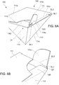
- Figures 3A , 4A , 5A , 6A , and 7A are front perspective views illustrating the behavior of a slit lock release gripping piece 111e of the present invention.
- Figures 3B , 4B , 5B , 6B , and 7B are rear perspective view respectively corresponding to Figures 3A , 4A , 5A , 6A , and 7A .
- Figure 8 is a front perspective view illustrating a state in which an openable lid 111 of the packing box 100 of the present invention is open.
- Figure 9A is a sectional side view as seen in the direction represented with reference numerals 9A-9A in Figure 1 .
- Figure 9B is a sectional side view as seen in the direction represented with reference numerals 9B-9B in Figure 3A .
- Figure 9C is a sectional side view as seen in the direction represented with reference numerals 9C-9C in Figure 5A .
- the packing box 100 of the first embodiment of the present invention is made of a thick coated cardboard, and includes a box body 110 that is an inverted quadrangular pyramid (pentahedron) as one example of a polyhedron having the openable lid 111 and being capable of housing a fancy box (not shown) as one example of a product, an insertion piece 120 that holds the openable lid 111, and left and right side flaps 130 and 140 as side flaps.
- a box body 110 that is an inverted quadrangular pyramid (pentahedron) as one example of a polyhedron having the openable lid 111 and being capable of housing a fancy box (not shown) as one example of a product
- an insertion piece 120 that holds the openable lid 111
- left and right side flaps 130 and 140 as side flaps.
- the openable lid 111 constitutes one face of the box body 110 that is an inverted quadrangular pyramid, and is provided so as to openably and closably swing around an openable base end folding ruled line BL1, which is a folding line, at a base end 111a to seal a product taking-in/out opening EE (see Figure 8 ) formed at a position of the one face.
- the insertion piece 120 is mutually connected to a front end edge 111c of the openable lid 111 via an openable front end edge folding ruled line BL2, which is a folding line, and is provided so as to be inserted into the box body 110 to hold the openable lid 111.
- the left side flap 130 is configured so as to mutually connect to a left side wall plate member 113, which is a lid side member located at a side with respect to the openable lid 111 and constitutes a part of the inverted quadrangular pyramid, via a left side wall upper end folding ruled line BL3, which is a folding line, at an openable lid side edge portion of the left side wall plate member 113 to prevent protrusion of the product.
- a left side wall plate member 113 which is a lid side member located at a side with respect to the openable lid 111 and constitutes a part of the inverted quadrangular pyramid, via a left side wall upper end folding ruled line BL3, which is a folding line, at an openable lid side edge portion of the left side wall plate member 113 to prevent protrusion of the product.
- the right side flap 140 is configured so as to mutually connect to a right side wall plate member 115, which is a lid side member located at a side with respect to the openable lid 111 and constitutes a part of the inverted quadrangular pyramid, via a right side wall upper end folding ruled line BL4, which is a folding line, at an openable lid side edge portion of the right side wall plate member 115 to prevent protrusion of the product.
- a right side wall plate member 115 which is a lid side member located at a side with respect to the openable lid 111 and constitutes a part of the inverted quadrangular pyramid, via a right side wall upper end folding ruled line BL4, which is a folding line, at an openable lid side edge portion of the right side wall plate member 115 to prevent protrusion of the product.
- the upside of the packing box 100 is where the openable lid 111 is located, the front side of the packing box 100 is where a front end edge 111c, which is a free end of the openable lid 111, is located, and the rear side of the packing box 100 is where the base end 111a is located,.
- left and right are defined with respect to the packing box 100 that has been constructed. In other words, “left” and “right” are left and right of the packing box 100 as seen from a rear wall plate member 112 toward a front wall plate member 114 of the packing box 100.
- the box body 110 having a shape of an inverted quadrangular pyramid includes the openable lid 111, the rear wall plate member 112, the left side wall plate member 113 as a lid side member, the front wall plate member 114, the right side wall plate member 115 as a lid side member, and a right side rear margin 116.
- the rear wall plate member 112 is connected to the base end 111a of the openable lid 111 via the openable base end folding ruled line BL1, which is a folding line.
- the left side wall plate member 113 is connected to a left end portion of the rear wall plate member 112 via a rear wall left end folding ruled line BL5, which is a folding line.
- the front wall plate member 114 is connected to a front end of the left side wall plate member 113 via a left side wall front end folding ruled line BL6, which is a folding line.
- the right side wall plate member 115 is connected to a right end portion of the front wall plate member 114 via a front wall right end folding ruled line BL7, which is a folding line.
- the right side rear margin 116 is connected to a rear end portion of the right side wall plate member 115 via a right side wall rear end folding ruled line BL8, which is a folding line.
- the rear wall plate member 112 or the left side wall plate member 113 is folded along the rear wall left end folding ruled line BL5 so that an angle therebetween becomes 90 degrees
- the left side wall plate member 113 or the front wall plate member 114 is folded along the left side wall front end folding ruled line BL6 so that an angle therebetween becomes 90 degrees.
- the front wall plate member 114 or the right side wall plate member 115 is folded along the front wall right end folding ruled line BL7 so that an angle therebetween becomes 90 degrees
- the right side wall plate member 115 or the right side rear margin 116 is folded along the right side wall rear end folding ruled line BL8 so that an angle therebetween becomes 90 degrees.
- the right side rear margin 116 is glued to an inner face of a right end portion of the rear wall plate member 112 with a glue, for example, to form side faces of the inverted quadrangular pyramid of the box body 110.
- left side flap 130 is folded rightward, or inward, along the left side wall upper end folding ruled line BL3
- the right side flap 140 is similarly folded leftward, or inward, along the right side wall upper end folding ruled line BL4.
- the openable lid 111 is folded forward, or inward, along the openable base end folding ruled line BL1, and the insertion piece 120 is folded downward, or inward, along the openable front end edge folding ruled line BL2.
- the packing box 100 has a slit lock engaging structure LK in which the openable lid 111 is maintained in a closed state by engaging a part of the side flap into a slit created by partially cutting a connection base end of the insertion piece 120 along the openable front end edge folding ruled line BL2.
- a left L-shaped cut CT1 and a right L-shaped cut CT2 exist in the vicinity of the openable front end edge folding ruled line BL2 of the insertion piece 120.
- a left slit SL1 and a right slit SL2 which are gaps between the insertion piece 120 and the openable lid 111, are formed.
- the slits are formed with the L-shaped cuts (CT1 and CT2). If the thickness of the material of the packing box 100 is relatively small, however, the slits may be formed with simple straight cuts, or I-shaped cuts.
- a left slit engaging piece 131 formed at a front end of the left side flap 130 then enters into the left slit SL1, making the insertion piece 120 being engaged by the left slit engaging piece 131 in the left slit SL1.
- a right slit engaging piece 141 formed at a front end of the right side flap 140 enters into the right slit SL2, making the insertion piece 120 being engaged by the right slit engaging piece 141 in the right slit SL2.
- a tear inducing line 111d which is a perforated line as one example, extends from a right flap opposing edge 111b, which is a flap opposing edge of the openable lid 111 opposing the side flap, to a front end edge 111c of the openable lid 111.
- a part of the openable lid 111 is torn along the tear inducing line 111d and is raised up with respect to the openable lid 111 by a human hand to form a slit lock release gripping piece 111e that can be used for releasing the engagement by the slit lock engaging structure LK.
- the slit lock release gripping piece 111e takes a slightly raised position with respect to the rest of the openable lid 111.
- the tear inducing line 111d is formed in an arc-like shape that is orthogonal to the right flap opposing edge 111b and the front end edge 111c of the openable lid 111.
- the direction of a stress acting on the tear inducing line 111d gradually changes from the direction orthogonal to the right flap opposing edge 111b of the openable lid 111 to the direction orthogonal to the front end edge 111c of the openable lid 111.
- the point on which the stress acts does not stay on a single location on the tear inducing line 111d but moves gradually from the right flap opposing edge 111b to the front end edge 111c of the openable lid 111 in an arc-like manner.
- the arc-like shape of the tear inducing line 111d is an arc of a precise circle whose center is located at a cross-point CP of the front end edge 111c and the right flap opposing edge 111b of the openable lid 111.
- the amount of the stress acting along the tear inducing line 111d is substantially equalized in accordance with the radius of the precise circle and a load acting from a human hand is also substantially homogenized.
- the slit lock release gripping piece 111e is raised up from the state illustrated in Figures 3A and 3B due to a pulling force in upward and forward directions created by a human hand.
- the insertion piece 120 is also pulled forward due to the pulling force created by a human hand from the state illustrated in Figures 4A and 4B .
- the right slit SL2 which is the slit at a side of the insertion piece 120 in a lateral direction of the insertion piece 120 where the slit lock release gripping piece 111e is formed, moves forward with respect to the right slit engaging piece 141 of the right side flap 140, allowing the right slit engaging piece 141 to be taken out of the right slit SL2.
- the packing box 100 has flexibility, the front wall plate member 114 deforms in a greater or lesser degree due to a forward pulling force created by a human hand, allowing the right slit SL2 to move forward.
- the slit lock release gripping piece 111e is pulled upward and forward from the state illustrated in Figures 5A and 5B due to a pulling force in upward and forward directions created by a human hand.
- the insertion piece 120 is also pulled upward and forward, causing the insertion piece 120 to move upward while the right slit engaging piece 141 is out of the right slit SL2.
- the openable lid 111 starts to open while being slightly twisted such that one side of the openable lid 111 in the lateral direction thereof where the slit lock release gripping piece 111e is formed precedes the other side of the openable lid 111 in the lateral direction thereof.
- the insertion piece 120 is inclined with respect to the lateral direction, and the engagement between the insertion piece 120 and the left slit engaging piece 131 of the left side flap 130 in the left slit SL1 at the other side of the openable lid 111 in the lateral direction thereof is loosened.
- the left slit SL1 then moves upward while being inclined with respect to the left slit engaging piece 131 of the left side flap 130, causing the left slit engaging piece 131 to be taken out of the left slit SL1.
- the slit lock can be released smoothly to open the openable lid 111.
- a fancy box housed in the packing box 100 can be taken out of the packing box 100 without using a tool such as a cutter.
- the right slit SL2 of the present invention is formed with the right L-shaped cut CT2 (see Figure 2 ) and the insertion piece 120 in a folded state with respect to the openable lid 111.
- the right L-shaped cut CT2 is formed by cutting from a start point on the openable front end edge folding ruled line BL2, which is a border between the insertion piece 120 and the openable lid 111, toward a side of the insertion piece 120 for a length that is at least equal to a thickness d1 of the right side flap 140 and then cutting toward a side end of the insertion piece 120.
- a part of the openable lid 111 that projects forward from the openable front end edge folding ruled line BL2, which is the border between the insertion piece 120 and the openable lid 111, due to the right L-shaped cut CT2 when the insertion piece 120 is in the folded state with respect to the openable lid 111 forms an unlock projection piece 111f.
- the unlock projection piece 111f is configured so as to abut against the right slit engaging piece 141 in the right slit SL2 when the slit lock release gripping piece 111e is raised up to release the engagement created by the slit lock engaging structure LK.
- the right slit engaging piece 141 enters into the right slit SL2 having a size that is at least equal to the thickness d1 of the right side flap 140 to engage the insertion piece 120.
- the unlock projection piece 111f projects forward from the openable front end edge folding ruled line BL2.
- the slit lock release gripping piece 111e which is a part of the openable lid 111, is torn along the tear inducing line 111d from the state illustrated in Figure 9A and gripped by a human hand.
- the slit lock release gripping piece 111e swings upward and forward around the openable front end edge folding ruled line BL2.
- the unlock projection piece 111f provided across the openable front end edge folding ruled line BL2 from the slit lock release gripping piece 111e swings downward and rearward so as to close the right slit SL2 and abuts against the right slit engaging piece 141 in the right slit SL2.
- the unlock projection piece 111f then pushes the right slit engaging piece 141 in the right slit SL2 rearward in a relative manner.
- the unlock projection piece 111f pushes a front end of the right slit engaging piece 141, causing the openable front end edge folding ruled line BL2 and the slit lock release gripping piece 111e, the insertion piece 120, and the right slit SL2 in the vicinity of the openable front end edge folding ruled line BL2 to further move forward and the front wall plate member 114 to further deflect forward.
- the right slit engaging piece 141 in the right slit SL2 is relatively pushed out of the right slit SL2, and the engagement between the insertion piece 120 and the right slit engaging piece 141 in the right slit SL2 is released.
- timing at which this engagement is completely released depends on the relative positions of the insertion piece 120 and the slit lock release gripping piece 111e. That is, the engagement is completely released when the insertion piece 120 and the slit lock release gripping piece 111e are approximately aligned on a straight line.
- the slit lock release gripping piece 111e is provided only on the right side in the lateral direction, it may be provided on the left side as well, or even on both sides of the lateral direction.
- the openable lid 111 is provided upward for the purpose of description, it may be provided downward or sideways.
- one face of the polyhedron is adapted as the openable lid 111
- multiple faces of the polyhedron may be adapted as the openable lid 111, so that a plurality of the openable lids 111 are provided.
- an open window may be formed on any one face of the polyhedron of the box body 110.
- the bar code on the product housed in the packing box 100 can be seen from outside through the open window.
- At least one of the slit lock release gripping piece 111e and the right side flap 140, or the right side flap 140 in this embodiment has a temporary gluing portion 142 on a face thereof opposing the other of the slit lock release gripping piece 111e and the right side flap 140, or the slit lock release gripping piece 111e in this embodiment.
- the temporary gluing portion 142 includes a glue applied thereto for gluing to, removing from, and regluing to the other.
- the insertion piece 120 is folded for approximately 120 degrees so as to from an acute angle with respect to the openable lid 111, and is inserted into the box body 110 along an inner surface of the front wall plate member 114, which is arranged at an acute angle with respect to the openable lid 111.
- the angle between the openable lid 111 and the front wall plate member 114 is an acute angle
- a tip portion of the insertion piece 120 is positioned closer to the base end of the openable lid 111 and the slit engaging piece of the side flap is inserted deeper into the slit in comparison with the case where the angle between the openable lid 111 and the front wall plate member 114 is a right angle.
- the angle between the openable lid 111 and the front wall plate member 114 is an acute angle, the configuration including the slit lock release gripping piece 111e is still effective even if the interior of the box body 110 is not tightly filled.
- the packing box 100 as the first embodiment of the present invention obtained as described above has a part of the openable lid 111 that can be torn along the tear inducing line 113d extending from the right flap opposing edge 111b opposing the right side flap 140 to the front end edge 111c of the openable lid 111 to form the slit lock release gripping piece 111e that can be used for releasing the engagement by the slit lock engaging structure LK by being torn along the tear inducing line 111d and raised up with respect to the openable lid 111 by a human hand, the engagement by the slit lock engaging structure LK, which is the engagement between the insertion piece 120 and the right side flap 140 in the right slit SL2 on the side in the lateral direction of the insertion piece 120 where the slit lock release gripping piece 111e is formed, can be easily released even if the interior of the box body 110 is tightly filled with a fancy box or the like.
- the right slit SL2 is formed with the right L-shaped cut CT2 formed by cutting from a start point on the openable front end edge folding ruled line BL2, which is a border between the insertion piece 120 and the openable lid 111, toward a side of the insertion piece 120 for a length that is at least equal to the thickness d1 of the right side flap 140 and then cutting toward a side end of the insertion piece 120 and the insertion piece 120 folded with respect to the openable lid 111, and a part of the openable lid 111 that projects forward from the openable front end edge folding ruled line BL2, which is the border between the insertion piece 120 and the openable lid 111, when the insertion piece 120 is folded with respect to the openable lid 111 forms the unlock projection piece 111f that is able to abut against the right slit engaging piece 141 in the right slit SL2 when the slit lock release gripping piece 111e is raised up to release the engagement created by the slit lock engaging structure LK,
- the tear inducing line 111d is formed in an arc-like shape that is orthogonal to the right flap opposing edge 111b and the front end edge 111c of the openable lid 111, the slit lock release gripping piece 111e can be formed by tearing along the tear inducing line 111d smoothly.
- the slit lock release gripping piece 111e can be formed by tearing along the tear inducing line 111d more smoothly.
- an open window is formed on any one face of the polyhedron, a user can check a product and a person in charge of product inspection, for example, can inspect a product.
- the slit lock release gripping piece 111e and the right side flap 140, or the right side flap 140 in this embodiment has a temporary gluing portion 142 on a face thereof opposing the other of the slit lock release gripping piece 111e and the right side flap 140, or the slit lock release gripping piece 111e in this embodiment, and the temporary gluing portion 142 includes a glue applied thereto for gluing to, removing from, and regluing to the other, the slit lock release gripping piece 111e can be returned to the position that is in the same plane as the openable lid 111, so that the packing box 100 can be used continuously with the slit rock even after the packing box 100 is once open and the slit rock is re-released as needed.
- a packing box 200 of a second embodiment of the present invention will now be described with reference to Figures 10 and 11 .
- Figure 10 is a perspective view schematically illustrating the packing box 200 of the second embodiment of the present invention
- Figure 11 is a development view of the packing box 200 of the second embodiment of the present invention.
- the packing box 200 of the second embodiment is a modified version of the packing box 100 of the first embodiment where the number and shape of the faces of the polyhedron are modified and has many elements that are common with the packing box 100 of the first embodiment. Thus, the common elements will be identified with similar numbers in 200s and will not be described in detail.
- the packing box 200 as the second embodiment of the present invention is made of a thick coated cardboard, and includes a box body 210 having a so-called semicyrindrical shape (octahedron) as one example of a polyhedron with two openable lid 211A, 211B and being capable of housing a product (not shown), left side flaps 230A, 230B and right side flaps 240A, 240B as side flaps, and insertion pieces 220A, 220B respectively holding the openable lids 211A, 211B.
- semicyrindrical shape octahedron
- the upside of the packing box 200 is where the openable lid 211A is located, the front side of the packing box 200 is where a front end edge 211Ac, which is a free end of the openable lid 211A, is located, and the rear side of the packing box 200 is where a base end 211Aa is located.
- the structure of a side of the openable lid 211B is similar to the structure of a side of the openable lid 211A and thus will not be described in detail.
- the packing box 200 is constructed by folding inwardly along each of folding lines BL and grueling a margin 216 to an inner face of a right side wall plate member 215 with a glue, for example, to form side faces of the semicylindrical shape (octahedron) of the box body 210.
- the packing box 200 of the second embodiment of the present invention obtained as described above has a part of the openable lid 211A that can be torn along a tear inducing line 211Ad extending from a right flap opposing edge 211Ab opposing the right side flap 240A to the front end edge 211Ac of the openable lid 211A to form a slit lock release gripping piece 211Ae that can be used for releasing the engagement by the slit lock engaging structure LK by being torn along the tear inducing line 211Ad and raised up with respect to the openable lid 211A by a human hand, the engagement by the slit lock engaging structure LK, which is the engagement between the insertion piece 220A and the right side flap 240A in the right slit SL2 on the side in the lateral direction of the insertion piece 220A where the slit lock release gripping piece 211Ae is formed, can be easily released even if the interior of the box body 210 is tightly filled with a product.
- a packing box 300 of a third embodiment of the present invention will now be described with reference to Figures 12 and 13 .
- Figure 12 is a perspective view schematically illustrating the packing box 300 of the third embodiment of the present invention
- Figure 13 is a development view of the packing box 300 of the third embodiment of the present invention.
- the packing box 300 of the third embodiment is a modified version of the packing box 200 of the second embodiment where some faces of the polyhedron are modified as curved faces and has many elements that are common with the packing box 200 of the second embodiment. Thus, the common elements will be identified with similar numbers in 300s and will not be described in detail.
- the packing box 300 of the third embodiment of the present invention is made of a thick coated cardboard, and includes a box body 310 having a so-called semicyrindrical shape (including two curved faces plus six flat faces) as one example of a polyhedron with two openable lid 311A, 311B and two curved faces and being capable of housing a product (not shown), left side flaps 330A, 330B and right side flaps 340A, 340B as side flaps, and insertion pieces 320A, 320B respectively holding the openable lids 311A, 311B.
- semicyrindrical shape including two curved faces plus six flat faces
- the upside of the packing box 300 is where the openable lid 311A is located, the front side of the packing box 300 is where a front end edge 311Ac, which is a free end of the openable lid 311A, is located, and the rear side of the packing box 300 is where a base end 311Aa is located.
- the structure of a side of the openable lid 311B is similar to the structure of a side of the openable lid 311A and thus will not be described in detail.
- the packing box 300 is constructed by folding a rear left curved surface 317 and a rear right curved surface 318 in an arc-like shape, folding other parts of the packing box 300 inwardly along each of folding lines BL, and grueling a margin 316 to an inner face of a right side wall plate member 315 with a glue, for example, to form side faces of the semicylindrical shape (having two curved faces plus six flat faces) of the box body 310.
- the packing box 300 of the third embodiment of the present invention obtained as described above has a part of the openable lid 311A that can be torn along a tear inducing line 311Ad extending from a right flap opposing edge 311Ab opposing the right side flap 340A to the front end edge 311Ac of the openable lid 311 to form a slit lock release gripping piece 311Ae that can be used for releasing the engagement by the slit lock engaging structure LK by being torn along the tear inducing line 311Ad and raised up with respect to the openable lid 311A by a human hand, the engagement by the slit lock engaging structure LK, which is the engagement between the insertion piece 320A and the right side flap 340A in the right slit SL2 on the side in the lateral direction of the insertion piece 320A where the slit lock release gripping piece 311Ae is formed, can be easily released even if the interior of the box body 310 is tightly filled with a product.
- the box body 310 of the packing box 300 is a polyhedron having curved faces such as the rear left curved surface 317 and the rear right curved surface 318, the same effects as the above-described second embodiment can be obtained.
- a packing box 400 of a fourth embodiment of the present invention will now be described with reference to Figures 14 and 15 .
- Figure 14 is a perspective view schematically illustrating the packing box 400 of the fourth embodiment of the present invention
- Figure 15 is a development view of the packing box 400 of the fourth embodiment of the present invention.
- the packing box 400 of the fourth embodiment is a modified version of the packing box 100 of the first embodiment where the number and shape of faces of the polyhedron as well as the number of the openable lids 111 are modified and has many elements that are common with the packing box 100 of the first embodiment. Thus, the common elements will be identified with similar numbers in 400s and will not be described in detail.
- the packing box 400 of the fourth embodiment of the present invention is made of a thick coated cardboard, and includes a box body 410 that is a so-called rhombicuboctahedron (icosihexahedron) as one example of a polyhedron having two openable lid 411A, 411B and being capable of housing a product (not shown), left side flaps 430A, 430B and right side flaps 440A, 440B as side flaps, and insertion pieces 420A, 420B respectively holding the openable lids 411A, 411B.
- rhombicuboctahedron icosihexahedron
- a box body 410 that is a so-called rhombicuboctahedron (icosihexahedron) as one example of a polyhedron having two openable lid 411A, 411B and being capable of housing a product (not shown), left side flaps 430A, 430B and right side flaps 440A, 440B
- the upside of the packing box 400 is where the openable lid 411A is located, the front side of the packing box 400 is where a front end edge 411Ac, which is a free end of the openable lid 411A, is located, and the rear side of the packing box 200 is where a base end 411Aa is located.
- the structure of a side of the openable lid 411B is similar to the structure of a side of the openable lid 411A and thus will not be described in detail.
- the packing box 400 is constructed by folding inward along each of folding lines BL, grueling each triangular margin 416A adjacent to a triangular face to an inner face of a rectangular plate members 412 adjacent to the triangular margins 416A with a glue, for example, and grueling a rectangular margin 416B to an inner face of a rear right side plate member 419 with a glue, for example.
- the left side flap 430A and the right side flap 440A are then folded inward, and an insertion piece 420A of the openable lid 411A is inserted into the box body 410 to form the rhombicuboctahedron (icosihexahedron) of the box body 410.
- the insertion piece 420A is folded at approximately 45 degrees so as to form an obtuse angle with respect to the openable lid 411A, and is inserted into the box body 410 along an inner surface of the front wall plate member 414, which is arranged at an obtuse angle with respect to the openable lid 411A.
- the angle between the openable lid 411A and the front wall plate member 414 is an obtuse angle, it is difficult to insert a human hand, or particularly a fingertip, between the insertion piece 420 and the front wall plate member 414, because a force does not act on the front wall plate member 414 in a direction to widen a space between the insertion piece 420 and the front wall plate member 414.
- the configuration including a slit lock release gripping piece 411Ae is still effective even if the interior of the box body 140 is not tightly filled.
- the packing box 400 of the fourth embodiment of the present invention obtained as described above has a part of the openable lid 411A that can be torn along a tear inducing line 411Ad extending from a left flap opposing edge 411Ab opposing a left side flap 430A to a front end edge 411Ac of the openable lid 411A to form the slit lock release gripping piece 411Ae that can be used for releasing the engagement by the slit lock engaging structure LK by being torn along the tear inducing line 411Ad and raised up with respect to the openable lid 411A by a human hand, the engagement by the slit lock engaging structure LK, which is the engagement between the insertion piece 420A and the left side flap 430A in the left slit SL1 on the side in the lateral direction of the insertion piece 420A where the slit lock release gripping piece 411Ae is formed, can be easily released even if the interior of the box body 410 is tightly filled with a product.
- a packing box 500 of a fifth embodiment of the present invention will now be described with reference to Figures 16 to 24 .
- Figure 16 is a front perspective view schematically illustrating the packing box 500 of the fifth embodiment of the present invention.
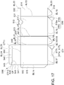
- Figure 17 is a development view of the packing box 500 of the fifth embodiment of the present invention.
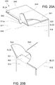
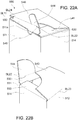
- Figures 18A , 19A , 20A , 21A , and 22A are front perspective views illustrating the behavior of a slit lock release gripping piece 544 of the present invention.
- Figures 18B , 19B , 20B , 21B , and 22B are rear perspective views respectively corresponding to Figures 18A , 19A , 20A , 21A , and 22A .
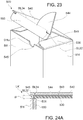
- Figure 23 is a front perspective view illustrating the state in which a top face lid 540, which is an openable lid of the packing box 500 of the present invention, is open.
- Figure 24A is a sectional side view as seen in the direction represented with reference numerals 24B-24B in Figure 18A .
- Figure 24B is a sectional side view as seen in the direction represented with reference numerals 24B-24B in Figure 18A .
- Figure 24C is a sectional side view as seen in the direction represented with reference numerals 24C-24C in Figure 19A .
- the packing box 500 of the fifth embodiment of the present invention is made of a thick coated cardboard, and includes an openable lid 540 that constitutes at least one face of a box body 510 for housing a product and that is freely swung around a base end to seal a product taking-in/out opening formed at a position of the one face, side flaps 520, 530 that are laterally positioned with respect to the openable lid 540 and are respectively connected to openable lid side edge portions of lid side members constituting parts of a polyhedron via a folding line to prevent protrusion of the product, and an insertion piece that is connected to a front end edge of the openable lid 540 via a folding line and that is inserted into the box body 510 to hold the openable lid 540.
- the packing box 500 includes the box body 510 to house a fancy box (not shown) as one example of the product, the right flap 520 and the left flap 530 as side flaps for preventing protrusion of the fancy box, the openable lid 540 consisting of the top face lid to openably seal an upper end portion of the box body 510, and an insertion piece 550 that is inserted into the box body 510 to hold the top face lid 540.
- the box body 510 includes the front wall plate member 511, the rear wall plate member 512, a plurality of side wall plate members including a right side wall plate member 513 and a left side wall plate member 514, a rear wall margin 515, and bottom plate members including a front side bottom plate member 516, a rear side bottom plate member 517, a right bottom plate member 518 and a left bottom plate member 519.
- the right side wall plate member 513 is connected to a right end portion of the front wall plate member 511 via a wall right end folding ruled line BL11, which is a folding line.
- the rear wall plate member 512 is connected to a rear end portion of the right side wall plate member 513 via a rear wall right end folding ruled line BL12, which is a folding line.
- the left side wall plate member 514 is connected to a left end portion of the front wall plate member 511 via a front wall left end folding ruled line BL13, which is a folding line.
- the rear wall margin 515 is connected to a left end portion of the rear wall plate member 512 via a rear wall left end folding ruled line BL14, which is a folding line.
- the front side bottom plate member 516 is connected to a lower end portion of the front wall plate member 511 via a front wall lower end folding ruled line BL15, which is a folding line.
- the front side bottom plate member 516 includes a front side bottom base 516a, a front side bottom margin 516b, and a front side bottom tongue piece 516c, and the front side bottom margin 516b is connected to the front side bottom base 516a via a front side bottom folding ruled line BL16, which is a folding line.
- the rear side bottom plate member 517 is connected to a lower end of the rear wall plate member 512 via a rear wall lower end folding ruled line BL17, which is a folding line.
- the rear side bottom plate member 517 includes a rear side bottom base 517a, a rear side bottom margin 517b, and a rear side bottom tongue piece 517c, and the rear side bottom margin 517b is connected to the rear side bottom base 517a via a rear side bottom folding ruled line BL18, which is a folding line.
- the right bottom plate member 518 is connected to a lower end of the right side wall plate member 513 via a right side wall lower end folding ruled line BL19, which is a folding line.
- the left bottom plate member 519 is connected to a lower end of the left side wall plate member 514 via a left side wall lower end folding ruled line BL20, which is a folding line.
- the front wall plate member 511 and the right side wall plate member 513 are folded with respect to each other along the front wall right end folding ruled line BL11 so that an angle therebetween becomes 90 degrees
- the right side wall plate member 513 and the rear wall plate member 512 are folded with respect to each other along the rear wall right end folding ruled line BL12 so that an angle therebetween becomes 90 degrees, for example.
- the front wall plate member 511 and the left side wall plate member 514 are folded with respect to each other along the front wall left end folding ruled line BL13 so that an angle therebetween becomes 90 degrees
- the rear wall plate member 512 and the rear wall margin 515 are folded with respect to each other along the rear wall left end folding ruled line BL14 so that an angle therebetween becomes 90 degrees.
- the rear wall margin 515 is glued to a rear end portion of an inner face of the left side wall plate member 514 with a glue, for example, making the outer circumference of the box body 510 rectangular in a planar view.
- the box body 510 is temporarily deformed so that the cross section of the box body 510 in a planar view becomes a parallelogram, and the front side bottom margin 516b is glued to an outer face of the left bottom plate member 519 with a glue, for example.
- the rear side bottom margin 517b is glued to an outer face of the right bottom plate member 518 with a glue, for example.
- the deformed the box body 510 is returned to the original state so that the shape of the cross section of the box body 510 in a planar view changes from the parallelogram to a rectangle having right angles.
- the front side bottom plate member 516 which is folded along the front side bottom folding ruled line BL16, becomes unfolded and the rear side bottom plate member 517, which is folded along the rear side bottom folding ruled line BL18, also becomes unfolded.
- the front side bottom tongue piece 516c is inserted into an inner face side of the rear side bottom base 517a and the rear side bottom tongue piece 517c is also inserted into an inner face side of the front side bottom base 516a.
- the front side bottom tongue piece 516c and the rear side bottom tongue piece 517c engage with each other, and an edge portion of the front side bottom base 516a and an edge portion of the rear side bottom base 517a engage with each other, making the box body 510 stable in a state where the cross section of the box body 510 in a planar view is rectangular, or where the box body 510 is able to house a fancy box.
- the right side flap 520 is connected to the openable lid side edge portion of the lid side member, that is, an upper end portion of the right side wall plate member 513, via a right side wall upper end folding ruled line BL21, which is a folding line.
- the left side flap 530 is connected to the openable lid side edge portion of the lid side member, that is, an upper end portion of the left side wall plate member 514, via a left side wall upper end folding ruled line BL22, which is a folding line.
- a base end of the top face lid 540 which is an openable lid, is connected to an upper end portion of the rear wall plate member 512 via a rear wall upper end folding ruled line BL23, which is a folding line.
- the insertion piece 550 is connected to a front end edge 542 of the top face lid 540 via a top face front end edge folding ruled line BL24, which is a folding line.
- the packing box 500 has a slit lock engaging structure LK in which the openable lid 540, or the top face lid, is maintained in a closed state by engaging a part of the side flap into a slit created by partially cutting a connection base end of the insertion piece 550 along the top face front end edge folding ruled line BL24.
- a right L-shaped cut CT11 and a left L-shaped cut CT22 exist in the vicinity of the top face front end edge folding ruled line BL24 of the insertion piece 550.
- a right slit SL11 and a left slit SL22 are formed.
- the slits are formed with the L-shaped cuts (CT11 and CT22). If the thickness of the material of the packing box 500 is relatively small, however, the slits may be formed with simple straight cuts, or I-shaped cuts.
- a right slit engaging piece 521 formed at a front end of the right side flap 520 then enters into the right slit SL11, making the insertion piece 550 being engaged by the right slit engaging piece 521 in the right slit SL11.
- a left slit engaging piece 531 formed at a front end of the left side flap 530 enters into the left slit SL22, making the insertion piece 550 being engaged by the left slit engaging piece 531 in the left slit SL22.
- a tear inducing line 543 which is a perforated line, for example, extends from a left flap opposing edge 541, which is a flap opposing edge of the top face lid 540 as an openable lid, to a front end edge 542 of the top face lid 540.
- top face lid 540 can be torn along the tear inducing line 543 and be raised up with respect to top face lid 540 by a human hand to form a slit lock release gripping piece 544 that can be used for releasing the engagement by the slit lock engaging structure LK.
- top face lid 540 when the top face lid 540 is opened from the state illustrated in Figure 16 , a part of the top face lid 540 is torn from the left flap opposing edge 541 of top face lid 540 due to a pulling force in upward and forward directions created by a human hand and forms the slit lock release gripping piece 544
- the slit lock release gripping piece 544 takes a slightly raised position with respect to the rest of the top face lid 540.
- the tear inducing line 543 is formed in an arc-like shape that is orthogonal to the left flap opposing edge 541 and the front end edge 542 of the top face lid 540 as an openable lid.
- the direction of a stress acting on the tear inducing line 543 gradually changes from the direction orthogonal to the left flap opposing edge 541 to the direction orthogonal to the front end edge 542 of the top face lid 540.
- the point on which the stress acts does not stay on a single location on the tear inducing line 543 but moves gradually from the left flap opposing edge 541 to the front end edge 542 of top face lid 540 in an arc-like manner.
- the arc-like shape of the tear inducing line 543 is an arc of a precise circle whose center is located at a cross-point CP of the front end edge 542 and the left flap opposing edge 541 of the top face lid 540.
- the amount of the stress acting along the tear inducing line 543 is substantially equalized in accordance with the radius of the precise circle and a load acting from a human hand is also substantially homogenized.
- the slit lock release gripping piece 544 is raised up from the state illustrated in Figures 18A and 18B due to a pulling force in upward and forward directions created by a human hand.
- the insertion piece 550 is also pulled forward due to the pulling force created by a human hand from the state illustrated in Figures 19A and 19B .
- the left slit SL22 which is the slit at a side of insertion piece 550 in a lateral direction of the insertion piece 550 where slit lock release gripping piece 544 is formed, moves forward with respect to the left slit engaging piece 531 of the left side flap 530, allowing the left slit engaging piece 531 to be taken out of the left slit SL22.
- the packing box 500 has flexibility, the front wall plate member 511 deforms in a greater or lesser degree due to a forward pulling force created by a human hand, allowing the left slit SL22 to move forward.
- the slit lock release gripping piece 544 is pulled upward and forward from the state illustrated in Figures 20A and 20B due to the pulling force in upward and forward directions created by a human hand.
- the insertion piece 550 is also pulled upward and forward, causing the insertion piece 550 to move upward while the left slit engaging piece 531 is out of the left slit SL22.
- the top face lid 540 starts to open while being slightly twisted such that one side of the top face lid 540 in the lateral directin thereof where the slit lock release gripping piece 544 is formed precedes the other side of the top face lid 540 in the lateral direction thereof.
- the insertion piece 550 is inclined with respect to the lateral direction, and the engagement between the insertion piece 550 and the right slit engaging piece 521 of the right side flap 520 in the right slit SL11 at the other side of the top face lid 540 in the lateral direction thereof is loosened.
- the right slit SL11 then moves upward while being inclined with respect to the right slit engaging piece 521 of the right side flap 520, causing right slit engaging piece 521 to be taken out of the right slit SL11.
- the slit lock can be released smoothly to open the top face lid 540.
- a fancy box housed in the packing box 500 can be taken out of the packing box 500 without using a tool such as a cutter.
- the left slit SL22 of the present invention is formed with the left L-shaped cut CT22 (see Figure 17 ) and the insertion piece 550 in a folded state with respect to the top face lid 540.
- the left L-shaped cut CT22 is formed by cutting from a start point on the top face front end edge folding ruled line BL24, which is a border between the insertion piece 550 and the top face lid 540, toward a side of the insertion piece 550 for a length that is at least equal to a thickness d1 of the left side flap 530 and then cutting toward a side end of the insertion piece 550.
- top face lid 540 that projects forward from the top face front end edge folding ruled line BL24, which is the border between the insertion piece 550 and the top face lid 540, due to the left L-shaped cut CT22 while the insertion piece 550 is in the folded state with respect to the top face lid 540 forms an unlock projection piece 545.
- the unlock projection piece 545 is configured so as to abut against the left slit engaging piece 531 in the left slit SL22 when the slit lock release gripping piece 544 is raised up to release the engagement created by the slit lock engaging structure LK.
- the left slit engaging piece 531 enters into the left slit SL22 having a size that is at least equal to the thickness d1 of the left side flap 530 to engage the insertion piece 550.
- the unlock projection piece 545 projects forward from the top face front end edge folding ruled line BL24.
- the slit lock release gripping piece 544 which is a part of the top face lid 540, is torn along the tear inducing line 543 from the state illustrated in Figure 24A and gripped by a human hand.
- the slit lock release gripping piece 544 swings upward and forward around the top face front end edge folding ruled line BL24.
- the unlock projection piece 545 provided across the top face front end edge folding ruled line BL24 from the slit lock release gripping piece 544 swings downward and rearward so as to close the left slit SL22 and abuts against left slit engaging piece 531 in the left slit SL22.
- the unlock projection piece 545 then pushes the left slit engaging piece 531 in the left slit SL22 rearward in a relative manner.
- the unlock projection piece 545 pushes a front end of the left slit engaging piece 531, causing the top face front end edge folding ruled line BL24 and the slit lock release gripping piece 544, the insertion piece 550, and the left slit SL22 in the vicinity of the top face front end edge folding ruled line BL24 to further move forward and the front wall plate member 511 to further deflect forward.
- the left slit engaging piece 531 in the left slit SL22 is relatively pushed out of the left slit SL22, and the engagement between the insertion piece 550 and the left slit engaging piece 531 in the left slit SL22 is released.
- a cutout portion 511a having an arc-like shape as one example is provided in an upper end portion of the front wall plate member 511 so as to oppose the tear inducing line 543 at the front end edge 542 of the top face lid 540.
- the shape of the cutout portion 511a is not restricted to the arc-like shape: it may be a V-shape or a U-shape, for example.
- slit lock release gripping piece 544 is provided only on the left side in the lateral direction, it may be provided on the right side or even on both sides of the lateral direction.
- the packing box 500 of the fifth embodiment of the present invention obtained as described above has a part of the top face lid 540 that can be torn along the tear inducing line 543 extending from the left flap opposing edge 541, which is a flap opposing edge of the top face lid 540, to the front end edge 542 of the top face lid 540 to form the slit lock release gripping piece 544 that can be used for releasing the engagement by the slit lock engaging structure LK by being torn along the tear inducing line 543 and raised up with respect to the top face lid 540 by a human hand, the engagement by the slit lock engaging structure LK, which is the engagement between the insertion piece 550 and the left side flap 530 in the left slit SL22 on the side in the lateral direction of the insertion piece 550 where the slit lock release gripping piece 544 is formed, can be easily released even if the interior of the box body 510 is tightly filled with a fancy box or the like.
- the left slit SL22 is formed with the left L-shaped cut CT22 formed by cutting from a start point on the top face front end edge folding ruled line BL24, which is a border between the insertion piece 550 and the top face lid 540, toward a side of the insertion piece 550 for a length that is at least equal to the thickness d1 of the side flap and then cutting toward a side end of the insertion piece 550 and the insertion piece 520 folded with respect to the top face lid 540, and a part of the top face lid 540 that projects forward from the openable front top face front end edge folding ruled line BL24, which is the border between the insertion piece 550 and the top face lid 540, when the insertion piece 520 is folded with respect to the top face lid 540 forms the unlock projection piece 545 that is able to abut against the left side flap 530 in the slit when the slit lock release gripping piece 544 is raised up to release the engagement created by the slit lock engaging structure LK,
- the tear inducing line 543 is formed in an arc-like shape that is orthogonal to the left flap opposing edge 541 and front end edge 542 of the top face lid 540, the slit lock release gripping piece 544 can be formed by tearing along the tear inducing line 543 smoothly.
- the slit lock release gripping piece 544 can be formed by tearing along the tear inducing line 543 more smoothly.
- the cutout portion 511a is provided in the upper end portion of the front wall plate member 511 so as to oppose the tear inducing line 543 at the front end edge 542 of the top face lid 540, the engagement by the slit lock engaging structure LK on the side in the lateral direction of the insertion piece 550 where the slit lock release gripping piece 544 is formed can be released more easily, and a break that tends to occur at this point can be suppressed so that the engagement between the insertion piece 550 and the left side flap 530 in the left slit SL22 created by the slit lock engaging structure LK can be more reliably released.
- a packing box 600 of a sixth embodiment of the present invention will now be described with reference to Figure 25A .
- Figure 25A is a front perspective view illustrating the packing box 600 of the sixth embodiment of the present invention.
- the packing box 600 of the sixth embodiment is a modified version of the packing box 500 of the fifth embodiment in which a flap opposing edge cutout 646 is formed at a position where the tear inducing line 543 reaches the left flap opposing edge 541 of the top face lid 540, and has many elements that are common with the packing box 500 of the fifth embodiment. Thus, the common elements will be identified with similar numbers in 600s and will not be described in detail.
- the packing box 600 of the sixth embodiment of the present invention has the flap opposing edge cutout 646 that is formed at a position where a tear inducing line 643 reaches a left flap opposing edge 641 of a top face lid 640.
- a fingertip of a human hand can easily catch on the flap opposing edge cutout 646, making it easier to insert the fingertip between a slit lock release gripping piece 644, which is a part of the top face lid 640, and a left side flap 630.
- the slit lock release gripping piece 644 can be easily torn along tear inducing line 643 and raised up.
- a packing box 700 of a seventh embodiment of the present invention will now be described with reference to Figure 25B .
- Figure 25B is a front perspective view illustrating the packing box 700 of the seventh embodiment of the present invention.
- the packing box 700 of the seventh embodiment is a modified version of the packing box 500 of the fifth embodiment where a flap opposing edge projecting piece 747 is formed on the left flap opposing edge 541 in a portion anterior to the tear inducing line 543 on the top face lid 540, and has many elements that are common with the packing box 500 of the fifth embodiment. Thus, the common elements will be identified with similar numbers in 700s and will not be described in detail.
- the packing box 700 of the sixth embodiment of the present invention has the flap opposing edge projecting piece 747 that is formed on a left flap opposing edge 741 in a portion anterior to a tear inducing line 743 on a top face lid 740.
- the flap opposing edge projecting piece 747 projects in a left side of the lateral direction.
- a fingertip of a human hand can easily catch on the flap opposing edge projecting piece 747, making it easier to insert the fingertip between a flap opposing edge projecting piece 747, which is a part of the top face lid 740, and a left side flap 730.
- the slit lock release gripping piece 744 can be easily torn along tear inducing line 743 and raised up.
- a packing box 800 of an eighth embodiment of the present invention will now be described with reference to Figure 26 .
- Figure 26 is a development view of an upper part of the packing box of the eighth embodiment of the present invention.
- the packing box 800 of the eighth embodiment is a modified version of the packing box 500 of the fifth embodiment having a hexagonal-column shape, and has many elements that are common with the packing box 500 of the fifth embodiment. Thus, the common elements will be identified with similar numbers in 800s and will not be described in detail.
- the packing box 800 having a hexagonal-column shape of the eighth embodiment of the present invention includes a front wall plate member 811, a rear wall plate member 812, a right side wall plate member 813a, a right side wall plate member 813b, a left side wall plate member 814a, a left side wall plate member 814b, and a side wall margin 815.
- the packing box 800 having a hexagonal-column shape can tightly house fancy boxes having a triangular-column shape or fancy boxes having a quadrangular-column shape whose cross-section as seen in a plan view is a rhombus.
- the side wall margin 815 is glued to an inner face of the front wall plate member 811 with a glue, for example.
- the top face lid 840 has two insertion pieces 850a, 850b connected thereto.
- the insertion piece 850b is slit-locked by a right slit engaging piece 821 of a right side flap 820 connected to an upper end portion of the right side wall plate member 813a.
- the insertion piece 850a is slit-locked by a left slit engaging piece 831 of a left side flap 830 connected to an upper end portion of the left side wall plate member 814a.
- each of the insertion pieces 850a, 850b is slit-locked by a part of a front flap 860 connected to an upper end portion of the front wall plate member 811.
- the tear inducing line 843a extends from a left flap opposing edge 841a to a left insertion piece side edge portion 842a
- the tear inducing line 843b extends from a right flap opposing edge 841b to a right insertion piece side edge portion 842b.
- parts of the top face lid 840 as openable lids are torn along the tear inducing lines 843a, 843b with a pulling force created by a human hand to form slit lock release gripping pieces 844a, 844b.
- the engagement by the slit lock engaging structure LK which is the engagement between the insertion piece 850a and the left side flap 830 in a slit or the engagement between the insertion piece 850b and the right side flap 820 in a slit, can be released.
- the mechanism of releasing the slit lock is similar to those of the above-described embodiments and is thus not described in detail.
- the present invention particularly relates to a packing box that packs a product itself, such as a cosmetic, drug, food, or toy, or a fancy box that houses the product and is displayed on a sales floor, such as a store front, for protecting the product or the fancy box from being damaged or impacted during delivery of the product or the fancy box to the sales floor.
- a product itself such as a cosmetic, drug, food, or toy
- a fancy box that houses the product and is displayed on a sales floor, such as a store front, for protecting the product or the fancy box from being damaged or impacted during delivery of the product or the fancy box to the sales floor.
Abstract
Description
- The present invention relates to a packing box forming a slit lock engaging structure for retaining a state in which an openable lid is closed by engaging a portion of a side flap into a slit created by partially cutting a connection base end of an insertion piece along a folding line. Particularly, the present invention relates to a packing box that packs a product itself, such as a cosmetic, drug, food, or toy, or a fancy box that houses the product and is displayed on a sales floor, such as a store front, for protecting the product or the fancy box from being damaged or impacted during delivery of the product or the fancy box to the sales floor.
- As one example of the packing box, a packing case is conventionally known that includes an arc-like cutout portion formed at an upper end of a front face of box body overlapping an insertion piece and a push-in piece formed at a portion of the box body facing the cutout portion and surrounded with an arc-like cut so that a finger hook hole can be created, wherein the packing case is opened by hooking a finger into the finger hooking hole and pulling up a lid portion (see Patent Literature 1, for example).
- As another example of the packing box, an article storage box is known that includes cut lines (slits) provided at both ends of a border between a lid plate and an insertion piece and side flaps, wherein the article storage has a so-called slit lock structure in which the side flaps are hooked into the cut lines (slits) (see Patent Literatures 2 and 3, for example).
- As another example of the packing box, a sealed box is known that includes locking cuts formed at both end portions of a lateral folding line between a top face flap piece and a top face insertion flap piece and constituting a lock mechanism, locking projection pieces formed at base ends of inner top face flap pieces and constituting the lock mechanism, and a flange formed at a center portion of the top face flap piece and used as a start portion of tearing along tear inducing lines (see Patent Literature 4, for example).
- In a state in which the top face flap piece closes an opening of a tubular body, the top face insertion flap piece is anchored by inserting locking projection pieces into the locking cuts so that the state in which the top face flap piece closes the opening is maintained.
- An article stored in the sealed box can be taken out by tearing along the tear inducing lines.
- As another example of the packing box, a paper box is known that locks a lid plate in a closed state by engaging base portions at both ends of an insertion piece to front edge portions of lid pieces (side flaps) (see Patent Literature 5, for example).
- The paper box is opened by pushing a push-in portion, which is formed at a front portion of the lid plate with a folding line or a cut line, by a finger to create a depressed area and then inserting the finger into the depressed area to lift up the lid plate by the finger to unlock the lid plate.
- Similar paper boxes are disclosed by
JP 2007-253966 Figures 1 to 3 ),JP 2001-301741 Figure 1 ),JP 2007-209598 Figures 1 and2 ),JP 2013-1424 Figures 1 to 3 ),JP 2002-19766 Figures 1 to 10 ) andJP H10-77029 Figures 2 to 4 ). - However, because the conventional packing case of Patent Literature 1 has a structure in which the finger hook hole is created by pushing the push-in piece into the interior of the box body, the finger hook hole cannot be created for opening the lid portion when the interior of the box body is tightly filled with a fancy box or the like.
- Also, because the conventional article storage box described in Patent Literatures 2 and 3 has the structure in which the lid plate is opened by inserting a finger between the front plate and the insertion piece for deflecting the insertion piece to unhook the side flaps from the cut lines (slits), it is difficult to open the lid plate to take a fancy box or the like out of the article storage box when the interior of box body is tightly filled with the fancy box or the like so that a finger cannot be inserted between the front plate and the insertion piece for deflecting the insertion piece.
- Also, because the sealed box described in Patent Literature 4 has the structure in which a part of the top face flap piece is opened by tearing from the flange without unlocking the lock mechanism, it is difficult to take a fancy box or the like out of the sealed box when the interior of box body is tightly filled with the fancy box or the like, since the fancy box or the like gets caught on the rest of the top face flap piece.
- Also, because the paper box described in Patent Literature 5 has the structure in which the push-in portion is pushed by a finger for opening the lid plate, it is difficult to take a fancy box or the like out of the paper box when the interior of box body is tightly filled with the fancy box or the like, since the push-in portion cannot be pushed by a finger in the first place.
- Meanwhile, a suspended packing box is known that includes a suspension piece having a suspension hole formed with a separation line, such as a perforation line or a tear line, which extends from one side edge of an upper lid to a back face side of the upper lid (see Patent Literature 6, for example). However, the separation line is provided for simply forming a part of the upper lid as the suspension piece and has nothing to do with opening the upper lid.
- Thus, the object of the present invention, which has been achieved for addressing the above described problems, is to provide a packing box that can easily release a slit lock in which slits of an insertion piece of an openable lid engage with side flaps connected to openable lid side edge portions of lid side members, even if the interior of a box body of the packing box is tightly filled with a product.
- According to a first aspect of the present invention, the above-described problems are addressed by providing a packing box including an openable lid that constitutes at least one face of a box body, which is a polyhedron to house a product, and openably and closably swings around a base end to seal a product taking-in/out opening formed at a position of the one face, a side flap that is laterally located with respect to the openable lid and is connected via a folding line to an openable lid side edge portion of a lid side member constituting a part of the polyhedron for preventing protrusion of the product, and an insertion piece that is connected to a front end edge of the openable lid via a folding line and is inserted into the box body for holding the openable lid, the packing box constituting a slit lock engaging structure that maintains a state in which the openable lid is closed by engaging a part of the side flap into a slit created by cutting a part of a connection base end of the insertion piece along the folding line, wherein the openable lid includes a part that can be torn along a tear inducing line extending from a flap opposing edge of the openable lid opposing the side flap to a front end edge of the openable lid, and the part is held and torn along the tear inducing line by a human hand and is raised up with respect to the openable lid to form a slit lock release gripping piece that can be used for releasing engagement created by the slit lock engaging structure.
- According to a second aspect of the present invention, the above-described problems are further addressed by providing the packing box according to the first aspect, wherein the slit includes a L-shaped cut formed by cutting from a start point on a folding line, which is a border between the insertion piece and the openable lid, toward a side of the insertion piece for a length that is at least equal to a thickness of the side flap and then cutting toward a side end of the insertion piece, and the insertion piece is folded with respect to the openable lid for forming the slit, and a part of the openable lid projecting forward from the folding line when the insertion piece is folded with respect to the openable lid forms an unlock projection piece that is able to abut against the side flap in the slit when the slit lock release gripping piece is raised up to release the engagement created by the slit lock engaging structure.
- According to a third aspect of the present invention, the above-describes problems are further addressed by providing the packing box according to the first or second aspect, wherein the tear inducing line is formed in an arc-like shape that is orthogonal to the flap opposing edge and the front end edge of the openable lid.
- According to a fourth aspect of the present invention, the above-describes problems are further addressed by providing the packing box according to the third aspect, wherein the arc-like shape of the tear inducing line is an arc of a precise circle whose center is located at a cross-point of the front end edge and the flap opposing edge of the openable lid.
- According to a fifth aspect of the present invention, the above-describes problems are further addressed by providing the packing box according to the third aspect, wherein an open window is formed on any one face of the polyhedron.
- According to a sixth aspect of the present invention, the above-describes problems are further addressed by providing the packing box according to the third aspect, wherein at least one of the slit lock release gripping piece and the side flap has a temporary gluing portion on a face thereof opposing the other of the slit lock release gripping piece and the side flap, the temporary gluing portion including a glue applied thereto for gluing to, removing from, and regluing to the other of the slit lock release gripping piece and the side flap.
- According to a seventh aspect of the present invention, the above-describes problems are further addressed by providing the packing box according to the third aspect, wherein a cutout portion is provided in an upper end portion of a front wall plate member constituting at least one face of the box body so as to oppose the tear inducing line at the front end edge of the openable lid.
- Because the packing box of the present invention includes an openable lid that constitutes at least one face of a box body, which is a polyhedron to house a product, and openably and closably swings around a base end to seal a product taking-in/out opening formed at a position of the one face, a side flap that is laterally located with respect to the openable lid and is connected via a folding line to an openable lid side edge portion of a lid side member constituting a part of the polyhedron for preventing protrusion of the product, and an insertion piece that is connected to a front end edge of the openable lid via a folding line and is inserted into the box body for holding the openable lid, the packing box constituting a slit lock engaging structure that maintains a state in which the openable lid is closed by engaging a part of the side flap into a slit created by cutting a part of a connection base end of the insertion piece along the folding line, the packing box not only prevents the openable lid from being opened accidentally but also has the following unique effects.
- According to the packing box of the first aspect of the present invention, because the openable lid includes a part that can be torn along a tear inducing line extending from a flap opposing edge of the openable lid opposing the side flap to a front end edge of the openable lid, and the part is held and torn along the tear inducing line by a human hand and is raised up with respect to the openable lid to form a slit lock release gripping piece that can be used for releasing engagement created by the slit lock engaging structure, the slit lock release gripping piece is torn from the flap opposing edge of the openable lid along the tear inducing line and is raised up due to a pulling force in upward and forward directions created by a human hand when the openable lid is opened, the upward direction being the direction in which the openable lid opens, and the insertion piece is also pulled upward and forward as the slit lock release gripping piece is pulled upward and forward by a human hand so that the slit at a side of the insertion piece in a lateral direction of the insertion piece where the slit lock release gripping piece is formed moves forward with respect to the side flap, allowing the side flap to be taken out of the slit and the slit to move in the upward direction. Thus, the engagement by the slit lock engaging structure, which is the engagement between the insertion piece and the side flap in the slit on the side in the lateral direction of the insertion piece where the slit lock release gripping piece is formed, can be easily released even if the interior of the box body of the packing box is tightly filled.
- According to the packing box of the second aspect of the present invention, because the slit includes a L-shaped cut formed by cutting from a start point on a folding line, which is a border between the insertion piece and the openable lid, toward a side of the insertion piece for a length that is at least equal to a thickness of the side flap and then cutting toward a side end of the insertion piece, and the insertion piece is folded with respect to the openable lid for forming the slit, and a part of the openable lid projecting forward from the folding line when the insertion piece is folded with respect to the openable lid forms an unlock projection piece that is able to abut against the side flap in the slit when the slit lock
release gripping piece 111e is raised up to release the engagement created by the slit lock engaging structure, the unlock projection piece swings around the folding line to push the side flap out of the slit when the slit lock release gripping piece is raised up. Thus, the engagement by the slit lock engaging structure, which is the engagement between the insertion piece and the side flap in the slit on the side in the lateral direction of the insertion piece where the slit lock release gripping piece is formed, can be reliably released. - According to the packing box of the third aspect of the present invention, because the tear inducing line is formed in an arc-like shape that is orthogonal to the flap opposing edge and the front end edge of the openable lid, the direction of a stress acting on the tear inducing line gradually changes from the direction orthogonal to the flap opposing edge of the openable lid to the direction orthogonal to the front end edge of the openable lid when a part of the openable lid is raised up from the flap opposing edge by a human hand, and the point on which the stress acts does not stay on a single location on the tear inducing line but moves gradually from the flap opposing edge to the front end edge of the openable lid in an arc-like manner. Thus, the slit lock release gripping piece can be formed by tearing along the tear inducing line smoothly.
- According to the packing box of the fourth aspect of the present invention, because the arc-like shape of the tear inducing line is an arc of a precise circle whose center is located at a cross-point of the front end edge and the flap opposing edge of the openable lid, the amount of the stress acting along the tear inducing line is substantially equalized in accordance with the radius of the precise circle and a load acting from a human hand is also substantially equalized when a part of the openable lid is raised up from the flap opposing edge of the openable lid by a human hand. Thus, the slit lock release gripping piece can be formed by tearing along the tear inducing line more smoothly.
- According to the packing box of the fifth aspect of the present invention, because an open window is formed on any one face of the polyhedron, a product housed in the packing box can be seen from outside through the open window. Thus, a user can check the product.
- Also, the bar code of product information written on the product housed in the packing box can be seen from outside through the open window. Thus, a person in charge of product inspection, for example, can inspect the product.
- According to the packing box of the sixth aspect of the present invention, because at least one of the slit lock release gripping piece and the side flap has a temporary gluing portion on a face thereof opposing the other of the slit lock release gripping piece and the side flap, the temporary gluing portion including a glue applied thereto for gluing to, removing from, and regluing to the other of the slit lock release gripping piece and the side flap, the slit lock release gripping piece is temporarily glued in a position that is in the same plane as the openable lid. Thus, the slit lock release gripping piece can be returned to the position that is in the same plane as the openable lid even after the packing box is opened for continuously using the packing box, and the slit lock can be re-released as need arises.
- According to the packing box of the seventh aspect of the present invention, because a cutout portion is provided in an upper end portion of a front wall plate member constituting at least one face of the box body so as to oppose the tear inducing line at the front end edge of the openable lid, a portion of the front wall plate member near the slit lock release gripping piece can easily deflect forward and the insertion piece can be easily displaced forward when the slit lock release gripping piece is pulled upward and forward by the pulling force. Thus, the engagement by the slit lock engaging structure on the side in the lateral direction of the insertion piece where the slit lock release gripping piece is formed can be released more easily.
- Also, because the cutout portion is provided in the upper end portion of the front wall plate member constituting at least one face of the box body so as to oppose the tear inducing line at the front end edge of the openable lid, stress acting on an end point of the tear inducing line, which is a joint portion between the slit lock release gripping piece and the insertion piece, is dispersed when the slit lock release gripping piece is pulled upward and forward by the pulling force. Thus, a break that tends to occur at this point can be suppressed to more reliably release the engagement between the insertion piece and the side flap in the slit created by the slit lock engaging structure.
-
-
Figure 1 is a front perspective view schematically illustrating the packing box of a first embodiment of the present invention. -
Figure 2 is a development view of the packing box of the first embodiment of the present invention. -
Figure 3A is a front perspective view illustrating the behavior of the slit lock release gripping piece of the present invention. -
Figure 3B is a rear perspective view illustrating the behavior of the slit lock release gripping piece of the present invention. -
Figure 4A is a front perspective view illustrating the behavior of the slit lock release gripping piece of the present invention. -
Figure 4B is a rear perspective view illustrating the behavior of the slit lock release gripping piece of the present invention. -
Figure 5A is a front perspective view illustrating the behavior of the slit lock release gripping piece of the present invention. -
Figure 5B is a rear perspective view illustrating the behavior of the slit lock release gripping piece of the present invention. -
Figure 6A is a front perspective view illustrating the behavior of the slit lock release gripping piece of the present invention. -
Figure 6B is a rear perspective view illustrating the behavior of the slit lock release gripping piece of the present invention. -
Figure 7A is a front perspective view illustrating the behavior of the slit lock release gripping piece of the present invention. -
Figure 7B is a rear perspective view illustrating the behavior of the slit lock release gripping piece of the present invention. -
Figure 8 is a front perspective view illustrating the state in which the openable lid of the packing box of the present invention is open. -
Figure 9A is a sectional side view as seen in the direction indicated withreference numerals 9A-9A inFigure 1 . -
Figure 9B is a sectional side view as seen in the direction indicated withreference numerals 9B-9B inFigure 3A . -
Figure 9C is a sectional side view as seen in the direction indicated withreference numerals 9C-9C inFigure 5A . -
Figure 10 is a perspective view schematically illustrating the packing box of a second embodiment of the present invention. -
Figure 11 is a development view of the packing box of the second embodiment of the present invention. -
Figure 12 is a perspective view schematically illustrating the packing box of a third embodiment of the present invention. -
Figure 13 is a development view of the packing box of the third embodiment of the present invention. -
Figure 14 is a perspective view schematically illustrating the packing box of a fourth embodiment of the present invention. -
Figure 13 is a development view of the packing box of the fourth embodiment of the present invention. -
Figure 16 is a front perspective view schematically illustrating the packing box of a fifth embodiment of the present invention. -
Figure 17 is a development view of the packing box of the fifth embodiment of the present invention. -
Figure 18A is a front perspective view illustrating the behavior of the slit lock release gripping piece of the fifth embodiment. -
Figure 18B is a rear perspective view illustrating the behavior of the slit lock release gripping piece of the fifth embodiment. -
Figure 19A is a front perspective view illustrating the behavior of the slit lock release gripping piece of the fifth embodiment. -
Figure 19B is a rear perspective view illustrating the behavior of the slit lock release gripping piece of the fifth embodiment. -
Figure 20A is a front perspective view illustrating the behavior of the slit lock release gripping piece of the fifth embodiment. -
Figure 20B is a rear perspective view illustrating the behavior of the slit lock release gripping piece of the fifth embodiment. -
Figure 21A is a front perspective view illustrating the behavior of the slit lock release gripping piece of the fifth embodiment. -
Figure 21B is a rear perspective view illustrating the behavior of the slit lock release gripping piece of the fifth embodiment. -
Figure 22A is a front perspective view illustrating the behavior of the slit lock release gripping piece of the fifth embodiment. -
Figure 22B is a rear perspective view illustrating the behavior of the slit lock release gripping piece of the fifth embodiment. -
Figure 23 is a front perspective view illustrating the state in which the top face lid, which is the openable lid of the packing box of the fifth embodiment, is open. -
Figure 24A is a sectional side view as seen in the direction indicated withreference numerals 24A-24A inFigure 16 . -
Figure 24B is a sectional side view as seen in the direction indicated withreference numerals 24B-24B inFigure 18A . -
Figure 24C is a sectional side view as seen in the direction indicated withreference numerals 24C-24C inFigure 19A . -
Figure 25A is a front perspective view illustrating the packing box of a sixth embodiment. -
Figure 25B is a front perspective view illustrating the packing box of a seventh embodiment. -
Figure 26 is a development view of the upper portion of the packing box of an eighth embodiment of the present invention. - Details of embodiments of the present invention do not matter as long as the packing box provided by the present invention includes an openable lid that constitutes at least one face of a box body, which is a polyhedron to house a product, and openably and closably swings around a base end to seal a product taking-in/out opening formed at a position of the one face, a side flap that is laterally located with respect to the openable lid and is connected via a folding line to an openable lid side edge portion of a lid side member constituting a part of the polyhedron for preventing protrusion of the product, and an insertion piece that is connected to a front end edge of the openable lid via a folding line and is inserted into the box body for holding the openable lid, the packing box constituting a slit lock engaging structure that maintains a state in which the openable lid is closed by engaging a part of the side flap into a slit created by cutting a part of a connection base end of the insertion piece along the folding line, wherein the openable lid includes a part that can be torn along a tear inducing line extending from a flap opposing edge of the openable lid opposing the side flap to a front end edge of the openable lid, and the part is held and torn along the tear inducing line by a human hand and is raised up with respect to the openable lid to form a slit lock release gripping piece that can be used for releasing engagement created by the slit lock engaging structure, so that the engagement by the slit lock engaging structure, which is the engagement between the insertion piece and the side flap in the slit on the side in the lateral direction of the insertion piece where the slit lock release gripping piece is formed, can be easily released even if the interior of the box body of the packing box is tightly filled.
- For example, the packing box may have a shape of a polyhedron such as cube, cuboid, polygonal prism such as hexagonal prism, deltahedron, Platonic solid, or Archimedean solid, and faces of the polyhedron may include one or more types of shapes or sizes, as long as the packing box has the slit lock engaging structure in which a part of a side flap engages into a slit of an insertion piece connected to a front end side of an openable lid, and at least one face of the polyhedron constitutes the openable lid.
- The openable lid may be plural. Also, the openable lid may be consist of a single face of the polyhedron, or may be consist of adjacent multiple faces of the polyhedron.
- The slit may be a slit that is created with a simple partial cut line, and a slit that is created so as to have a certain amount of width, as with a cutout.
- Also, the material of the packing box may be a paper, such as a coated paper, a cardboard, or a coated cardboard, or a resin such as a plastic, as long as the material has enough flexibility for forming a polyhedron.
- Also, the tear inducing line may be straight or arc-like, as long as the tear inducing line extends from the flap opposing edge of the openable lid to the front end edge of the openable lid.
- Also, the tear inducing line may be a perforated line or a cut line, which is created by making small cuts along a desired line in predetermined intervals for easy tearing, or may be created by making the portion of the desired line thinner than the other portions so that tearing along the desired line can be easily executed.
- A
packing box 100 of a first embodiment of the present invention will now be described with reference toFigures 1 to 9 . -
Figure 1 is a front perspective view schematically illustrating thepacking box 100 of first embodiment of the present invention.Figure 2 is a development view of thepacking box 100 of the first embodiment of the present invention.Figures 3A ,4A ,5A ,6A , and7A are front perspective views illustrating the behavior of a slit lockrelease gripping piece 111e of the present invention.Figures 3B ,4B ,5B ,6B , and7B are rear perspective view respectively corresponding toFigures 3A ,4A ,5A ,6A , and7A .Figure 8 is a front perspective view illustrating a state in which anopenable lid 111 of thepacking box 100 of the present invention is open.Figure 9A is a sectional side view as seen in the direction represented withreference numerals 9A-9A inFigure 1 .Figure 9B is a sectional side view as seen in the direction represented withreference numerals 9B-9B inFigure 3A .Figure 9C is a sectional side view as seen in the direction represented withreference numerals 9C-9C inFigure 5A . - As illustrated in
Figures 1 and2 , thepacking box 100 of the first embodiment of the present invention is made of a thick coated cardboard, and includes abox body 110 that is an inverted quadrangular pyramid (pentahedron) as one example of a polyhedron having theopenable lid 111 and being capable of housing a fancy box (not shown) as one example of a product, aninsertion piece 120 that holds theopenable lid 111, and left and right side flaps 130 and 140 as side flaps. - The
openable lid 111 constitutes one face of thebox body 110 that is an inverted quadrangular pyramid, and is provided so as to openably and closably swing around an openable base end folding ruled line BL1, which is a folding line, at abase end 111a to seal a product taking-in/out opening EE (seeFigure 8 ) formed at a position of the one face. - The
insertion piece 120 is mutually connected to afront end edge 111c of theopenable lid 111 via an openable front end edge folding ruled line BL2, which is a folding line, and is provided so as to be inserted into thebox body 110 to hold theopenable lid 111. - The
left side flap 130 is configured so as to mutually connect to a left sidewall plate member 113, which is a lid side member located at a side with respect to theopenable lid 111 and constitutes a part of the inverted quadrangular pyramid, via a left side wall upper end folding ruled line BL3, which is a folding line, at an openable lid side edge portion of the left sidewall plate member 113 to prevent protrusion of the product. - Similar to the
left side flap 130, theright side flap 140 is configured so as to mutually connect to a right sidewall plate member 115, which is a lid side member located at a side with respect to theopenable lid 111 and constitutes a part of the inverted quadrangular pyramid, via a right side wall upper end folding ruled line BL4, which is a folding line, at an openable lid side edge portion of the right sidewall plate member 115 to prevent protrusion of the product. - In the description of the present embodiment, for the purpose of illustration, the upside of the
packing box 100 is where theopenable lid 111 is located, the front side of thepacking box 100 is where afront end edge 111c, which is a free end of theopenable lid 111, is located, and the rear side of thepacking box 100 is where thebase end 111a is located,. - Also, "left" and "right" are defined with respect to the
packing box 100 that has been constructed. In other words, "left" and "right" are left and right of thepacking box 100 as seen from a rearwall plate member 112 toward a frontwall plate member 114 of thepacking box 100. - As illustrated in
Figure 2 , thebox body 110 having a shape of an inverted quadrangular pyramid includes theopenable lid 111, the rearwall plate member 112, the left sidewall plate member 113 as a lid side member, the frontwall plate member 114, the right sidewall plate member 115 as a lid side member, and a right siderear margin 116. - The rear
wall plate member 112 is connected to thebase end 111a of theopenable lid 111 via the openable base end folding ruled line BL1, which is a folding line. - The left side
wall plate member 113 is connected to a left end portion of the rearwall plate member 112 via a rear wall left end folding ruled line BL5, which is a folding line. - The front
wall plate member 114 is connected to a front end of the left sidewall plate member 113 via a left side wall front end folding ruled line BL6, which is a folding line. - The right side
wall plate member 115 is connected to a right end portion of the frontwall plate member 114 via a front wall right end folding ruled line BL7, which is a folding line. - The right side
rear margin 116 is connected to a rear end portion of the right sidewall plate member 115 via a right side wall rear end folding ruled line BL8, which is a folding line. - When the
packing box 100 is constructed, the rearwall plate member 112 or the left sidewall plate member 113 is folded along the rear wall left end folding ruled line BL5 so that an angle therebetween becomes 90 degrees, and the left sidewall plate member 113 or the frontwall plate member 114 is folded along the left side wall front end folding ruled line BL6 so that an angle therebetween becomes 90 degrees. - Similarly, the front
wall plate member 114 or the right sidewall plate member 115 is folded along the front wall right end folding ruled line BL7 so that an angle therebetween becomes 90 degrees, and the right sidewall plate member 115 or the right siderear margin 116 is folded along the right side wall rear end folding ruled line BL8 so that an angle therebetween becomes 90 degrees. - Then, the right side
rear margin 116 is glued to an inner face of a right end portion of the rearwall plate member 112 with a glue, for example, to form side faces of the inverted quadrangular pyramid of thebox body 110. - Also, the
left side flap 130 is folded rightward, or inward, along the left side wall upper end folding ruled line BL3, and theright side flap 140 is similarly folded leftward, or inward, along the right side wall upper end folding ruled line BL4. - The
openable lid 111 is folded forward, or inward, along the openable base end folding ruled line BL1, and theinsertion piece 120 is folded downward, or inward, along the openable front end edge folding ruled line BL2. - The
packing box 100 has a slit lock engaging structure LK in which theopenable lid 111 is maintained in a closed state by engaging a part of the side flap into a slit created by partially cutting a connection base end of theinsertion piece 120 along the openable front end edge folding ruled line BL2. - Specifically, a left L-shaped cut CT1 and a right L-shaped cut CT2 exist in the vicinity of the openable front end edge folding ruled line BL2 of the
insertion piece 120. By folding theinsertion piece 120 along the openable front end edge folding ruled line BL2 toward theopenable lid 111, a left slit SL1 and a right slit SL2, which are gaps between theinsertion piece 120 and theopenable lid 111, are formed. - In the present embodiment, due to a relatively large thickness of the material of the
packing box 100, the slits (SL1 and SL2) are formed with the L-shaped cuts (CT1 and CT2). If the thickness of the material of thepacking box 100 is relatively small, however, the slits may be formed with simple straight cuts, or I-shaped cuts. - A left
slit engaging piece 131 formed at a front end of theleft side flap 130 then enters into the left slit SL1, making theinsertion piece 120 being engaged by the leftslit engaging piece 131 in the left slit SL1. - Similarly, a right
slit engaging piece 141 formed at a front end of theright side flap 140 enters into the right slit SL2, making theinsertion piece 120 being engaged by the rightslit engaging piece 141 in the right slit SL2. - In the present embodiment, a
tear inducing line 111d, which is a perforated line as one example, extends from a rightflap opposing edge 111b, which is a flap opposing edge of theopenable lid 111 opposing the side flap, to afront end edge 111c of theopenable lid 111. - A part of the
openable lid 111 is torn along thetear inducing line 111d and is raised up with respect to theopenable lid 111 by a human hand to form a slit lockrelease gripping piece 111e that can be used for releasing the engagement by the slit lock engaging structure LK. - Behavior and function of the slit lock
release gripping piece 111e will now be described. - As illustrated in
Figures 3A and 3B , when theopenable lid 111 is opened from the state illustrated inFigure 1 , a part of theopenable lid 111 is torn from the rightflap opposing edge 111b of theopenable lid 111 along thetear inducing line 111d due to a pulling force in upward and forward directions created by a human hand and forms the slit lockrelease gripping piece 111e. - At this moment, the slit lock
release gripping piece 111e takes a slightly raised position with respect to the rest of theopenable lid 111. - In the present embodiment, the
tear inducing line 111d is formed in an arc-like shape that is orthogonal to the rightflap opposing edge 111b and thefront end edge 111c of theopenable lid 111. - Thus, when a part of the
openable lid 111 is raised up from the rightflap opposing edge 111b by a human hand, the direction of a stress acting on thetear inducing line 111d gradually changes from the direction orthogonal to the rightflap opposing edge 111b of theopenable lid 111 to the direction orthogonal to thefront end edge 111c of theopenable lid 111. - Also, the point on which the stress acts does not stay on a single location on the
tear inducing line 111d but moves gradually from the rightflap opposing edge 111b to thefront end edge 111c of theopenable lid 111 in an arc-like manner. - That is, the tearing along the
tear inducing line 111d is executed smoothly. - Also, the arc-like shape of the
tear inducing line 111d is an arc of a precise circle whose center is located at a cross-point CP of thefront end edge 111c and the rightflap opposing edge 111b of theopenable lid 111. - Thus, when a part of the
openable lid 111 is raised up from the rightflap opposing edge 111b of theopenable lid 111 by a human hand, the amount of the stress acting along thetear inducing line 111d is substantially equalized in accordance with the radius of the precise circle and a load acting from a human hand is also substantially homogenized. - That is, the tearing along the
tear inducing line 111d is executed more smoothly. - As illustrated in
Figures 4A and 4B , the slit lockrelease gripping piece 111e is raised up from the state illustrated inFigures 3A and 3B due to a pulling force in upward and forward directions created by a human hand. - As illustrated in
Figures 5A and 5B , theinsertion piece 120 is also pulled forward due to the pulling force created by a human hand from the state illustrated inFigures 4A and 4B . - Then, the right slit SL2, which is the slit at a side of the
insertion piece 120 in a lateral direction of theinsertion piece 120 where the slit lockrelease gripping piece 111e is formed, moves forward with respect to the rightslit engaging piece 141 of theright side flap 140, allowing the rightslit engaging piece 141 to be taken out of the right slit SL2. - That is, the engagement between the
insertion piece 120 and the rightslit engaging piece 141 in the right slit SL2 is released. - It is noted that, because the
packing box 100 has flexibility, the frontwall plate member 114 deforms in a greater or lesser degree due to a forward pulling force created by a human hand, allowing the right slit SL2 to move forward. - As illustrated in
Figures 6A and 6B , the slit lockrelease gripping piece 111e is pulled upward and forward from the state illustrated inFigures 5A and 5B due to a pulling force in upward and forward directions created by a human hand. - Then, the
insertion piece 120 is also pulled upward and forward, causing theinsertion piece 120 to move upward while the rightslit engaging piece 141 is out of the right slit SL2. - As illustrated in
Figures 7A and 7B , due to the pulling force in upward and forward directions created by a human hand in the state illustrated inFigures 6A and 6B , theopenable lid 111 starts to open while being slightly twisted such that one side of theopenable lid 111 in the lateral direction thereof where the slit lockrelease gripping piece 111e is formed precedes the other side of theopenable lid 111 in the lateral direction thereof. - At this point, the
insertion piece 120 is inclined with respect to the lateral direction, and the engagement between theinsertion piece 120 and the leftslit engaging piece 131 of theleft side flap 130 in the left slit SL1 at the other side of theopenable lid 111 in the lateral direction thereof is loosened. - The left slit SL1 then moves upward while being inclined with respect to the left
slit engaging piece 131 of theleft side flap 130, causing the leftslit engaging piece 131 to be taken out of the left slit SL1. - That is, the engagement between the
insertion piece 120 and the leftslit engaging piece 131 in the left slit SL1 is released. - Next, as illustrated in
Figure 8 , due to an upward pulling force created by a human hand in the state illustrated inFigures 7A and 7B , theinsertion piece 120 is taken out of thebox body 110, and theopenable lid 111 becomes an open state. - As described above, because the pulling force created by a human hand acts upward and forward and the direction of the pulling force does not need to be inverted, the slit lock can be released smoothly to open the
openable lid 111. - Also, a fancy box housed in the
packing box 100 can be taken out of thepacking box 100 without using a tool such as a cutter. - Furthermore, as illustrated in
Figures 9A to 9C , the right slit SL2 of the present invention is formed with the right L-shaped cut CT2 (seeFigure 2 ) and theinsertion piece 120 in a folded state with respect to theopenable lid 111. - The right L-shaped cut CT2 is formed by cutting from a start point on the openable front end edge folding ruled line BL2, which is a border between the
insertion piece 120 and theopenable lid 111, toward a side of theinsertion piece 120 for a length that is at least equal to a thickness d1 of theright side flap 140 and then cutting toward a side end of theinsertion piece 120. - Also, a part of the
openable lid 111 that projects forward from the openable front end edge folding ruled line BL2, which is the border between theinsertion piece 120 and theopenable lid 111, due to the right L-shaped cut CT2 when theinsertion piece 120 is in the folded state with respect to theopenable lid 111 forms anunlock projection piece 111f. - The
unlock projection piece 111f is configured so as to abut against the rightslit engaging piece 141 in the right slit SL2 when the slit lockrelease gripping piece 111e is raised up to release the engagement created by the slit lock engaging structure LK. - Behavior and function of the
unlock projection piece 111f will now be described. - As illustrated in
Figure 9A , the rightslit engaging piece 141 enters into the right slit SL2 having a size that is at least equal to the thickness d1 of theright side flap 140 to engage theinsertion piece 120. - Also, the
unlock projection piece 111f projects forward from the openable front end edge folding ruled line BL2. - As illustrated in
Figure 9B , the slit lockrelease gripping piece 111e, which is a part of theopenable lid 111, is torn along thetear inducing line 111d from the state illustrated inFigure 9A and gripped by a human hand. - Then, due to a pulling force acting in upward and forward directions created by a human hand, the slit lock
release gripping piece 111e swings upward and forward around the openable front end edge folding ruled line BL2. - At this moment, the
unlock projection piece 111f provided across the openable front end edge folding ruled line BL2 from the slit lockrelease gripping piece 111e swings downward and rearward so as to close the right slit SL2 and abuts against the rightslit engaging piece 141 in the right slit SL2. - The
unlock projection piece 111f then pushes the rightslit engaging piece 141 in the right slit SL2 rearward in a relative manner. - At this moment, due to a reaction force from the right
slit engaging piece 141, the openable front end edge folding ruled line BL2 and the slit lockrelease gripping piece 111e, theinsertion piece 120 and the right slit SL2 in the vicinity of the openable front end edge folding ruled line BL2 slightly moves forward and the frontwall plate member 114 deflects forward. - As illustrated in
Figure 9C , when the slit lockrelease gripping piece 111e further swings and is raised up by a human hand from the state illustrated inFigure 9B , theunlock projection piece 111f closes the right slit SL2. - Then, the
unlock projection piece 111f pushes a front end of the rightslit engaging piece 141, causing the openable front end edge folding ruled line BL2 and the slit lockrelease gripping piece 111e, theinsertion piece 120, and the right slit SL2 in the vicinity of the openable front end edge folding ruled line BL2 to further move forward and the frontwall plate member 114 to further deflect forward. - Accordingly, the right
slit engaging piece 141 in the right slit SL2 is relatively pushed out of the right slit SL2, and the engagement between theinsertion piece 120 and the rightslit engaging piece 141 in the right slit SL2 is released. - In other words, because the
unlock projection piece 111f is provided, the engagement between theinsertion piece 120 and the rightslit engaging piece 141 in the right slit SL2 is released at a timing somewhere betweenFigures 4A and5B , which makes it easier to open theopenable lid 111. - It is noted that the timing at which this engagement is completely released depends on the relative positions of the
insertion piece 120 and the slit lockrelease gripping piece 111e. That is, the engagement is completely released when theinsertion piece 120 and the slit lockrelease gripping piece 111e are approximately aligned on a straight line. - Although in the present embodiment the slit lock
release gripping piece 111e is provided only on the right side in the lateral direction, it may be provided on the left side as well, or even on both sides of the lateral direction. - Also, although the
openable lid 111 is provided upward for the purpose of description, it may be provided downward or sideways. - Also, although in the present embodiment one face of the polyhedron is adapted as the
openable lid 111, multiple faces of the polyhedron may be adapted as theopenable lid 111, so that a plurality of theopenable lids 111 are provided. - Also, an open window may be formed on any one face of the polyhedron of the
box body 110. - This enables to see a product housed in the
packing box 100 from outside through the open window. - Also, by housing a product so that a bar code of product information labeled on the product is aligned with the position of the open window, the bar code on the product housed in the
packing box 100 can be seen from outside through the open window. - Furthermore, at least one of the slit lock
release gripping piece 111e and theright side flap 140, or theright side flap 140 in this embodiment, has atemporary gluing portion 142 on a face thereof opposing the other of the slit lockrelease gripping piece 111e and theright side flap 140, or the slit lockrelease gripping piece 111e in this embodiment. Thetemporary gluing portion 142 includes a glue applied thereto for gluing to, removing from, and regluing to the other. - This enables the slit lock
release gripping piece 111e to be temporarily glued so as to be in the same plane as theopenable lid 111. - It is noted that, in the present embodiment, the
insertion piece 120 is folded for approximately 120 degrees so as to from an acute angle with respect to theopenable lid 111, and is inserted into thebox body 110 along an inner surface of the frontwall plate member 114, which is arranged at an acute angle with respect to theopenable lid 111. - When the angle between the
openable lid 111 and the frontwall plate member 114 is an acute angle, a tip portion of theinsertion piece 120 is positioned closer to the base end of theopenable lid 111 and the slit engaging piece of the side flap is inserted deeper into the slit in comparison with the case where the angle between theopenable lid 111 and the frontwall plate member 114 is a right angle. Thus, it is difficult to release the slit lock by inserting a human hand, or a fingertip, between theinsertion piece 120 and the frontwall plate member 114. - Therefore, when the angle between the
openable lid 111 and the frontwall plate member 114 is an acute angle, the configuration including the slit lockrelease gripping piece 111e is still effective even if the interior of thebox body 110 is not tightly filled. - Because the
packing box 100 as the first embodiment of the present invention obtained as described above has a part of theopenable lid 111 that can be torn along the tear inducing line 113d extending from the rightflap opposing edge 111b opposing theright side flap 140 to thefront end edge 111c of theopenable lid 111 to form the slit lockrelease gripping piece 111e that can be used for releasing the engagement by the slit lock engaging structure LK by being torn along thetear inducing line 111d and raised up with respect to theopenable lid 111 by a human hand, the engagement by the slit lock engaging structure LK, which is the engagement between theinsertion piece 120 and theright side flap 140 in the right slit SL2 on the side in the lateral direction of theinsertion piece 120 where the slit lockrelease gripping piece 111e is formed, can be easily released even if the interior of thebox body 110 is tightly filled with a fancy box or the like. - Also, because the right slit SL2 is formed with the right L-shaped cut CT2 formed by cutting from a start point on the openable front end edge folding ruled line BL2, which is a border between the insertion piece 120 and the openable lid 111, toward a side of the insertion piece 120 for a length that is at least equal to the thickness d1 of the right side flap 140 and then cutting toward a side end of the insertion piece 120 and the insertion piece 120 folded with respect to the openable lid 111, and a part of the openable lid 111 that projects forward from the openable front end edge folding ruled line BL2, which is the border between the insertion piece 120 and the openable lid 111, when the insertion piece 120 is folded with respect to the openable lid 111 forms the unlock projection piece 111f that is able to abut against the right slit engaging piece 141 in the right slit SL2 when the slit lock release gripping piece 111e is raised up to release the engagement created by the slit lock engaging structure LK, the engagement by the slit lock engaging structure LK, which is the engagement between the insertion piece 120 and the right side flap 140 in the right slit SL2 on the side in the lateral direction of the insertion piece 120 where the slit lock release gripping piece 111e is formed, can be reliably released.
- Also, because the
tear inducing line 111d is formed in an arc-like shape that is orthogonal to the rightflap opposing edge 111b and thefront end edge 111c of theopenable lid 111, the slit lockrelease gripping piece 111e can be formed by tearing along thetear inducing line 111d smoothly. - Also, because the arc-like shape of the
tear inducing line 111d is an arc of a precise circle whose center is located at the cross-point CP of thefront end edge 111c and the rightflap opposing edge 111b of theopenable lid 111, the slit lockrelease gripping piece 111e can be formed by tearing along thetear inducing line 111d more smoothly. - Also, because an open window is formed on any one face of the polyhedron, a user can check a product and a person in charge of product inspection, for example, can inspect a product.
- Also, because at least one of the slit lock
release gripping piece 111e and theright side flap 140, or theright side flap 140 in this embodiment, has atemporary gluing portion 142 on a face thereof opposing the other of the slit lockrelease gripping piece 111e and theright side flap 140, or the slit lockrelease gripping piece 111e in this embodiment, and thetemporary gluing portion 142 includes a glue applied thereto for gluing to, removing from, and regluing to the other, the slit lockrelease gripping piece 111e can be returned to the position that is in the same plane as theopenable lid 111, so that thepacking box 100 can be used continuously with the slit rock even after thepacking box 100 is once open and the slit rock is re-released as needed. - A
packing box 200 of a second embodiment of the present invention will now be described with reference toFigures 10 and11 . -
Figure 10 is a perspective view schematically illustrating thepacking box 200 of the second embodiment of the present invention, andFigure 11 is a development view of thepacking box 200 of the second embodiment of the present invention. - The
packing box 200 of the second embodiment is a modified version of thepacking box 100 of the first embodiment where the number and shape of the faces of the polyhedron are modified and has many elements that are common with thepacking box 100 of the first embodiment. Thus, the common elements will be identified with similar numbers in 200s and will not be described in detail. - As illustrated in
Figures 10 and11 , thepacking box 200 as the second embodiment of the present invention is made of a thick coated cardboard, and includes abox body 210 having a so-called semicyrindrical shape (octahedron) as one example of a polyhedron with twoopenable lid insertion pieces openable lids - In the description of the present embodiment, for the purpose of illustration, the upside of the
packing box 200 is where theopenable lid 211A is located, the front side of thepacking box 200 is where a front end edge 211Ac, which is a free end of theopenable lid 211A, is located, and the rear side of thepacking box 200 is where a base end 211Aa is located. - The structure of a side of the
openable lid 211B is similar to the structure of a side of theopenable lid 211A and thus will not be described in detail. - The
packing box 200 is constructed by folding inwardly along each of folding lines BL and grueling amargin 216 to an inner face of a right sidewall plate member 215 with a glue, for example, to form side faces of the semicylindrical shape (octahedron) of thebox body 210. - The rest of the construction procedure is similar to that of the above-described first embodiment and thus will not be described in detail.
- Because the
packing box 200 of the second embodiment of the present invention obtained as described above has a part of theopenable lid 211A that can be torn along a tear inducing line 211Ad extending from a right flap opposing edge 211Ab opposing theright side flap 240A to the front end edge 211Ac of theopenable lid 211A to form a slit lock release gripping piece 211Ae that can be used for releasing the engagement by the slit lock engaging structure LK by being torn along the tear inducing line 211Ad and raised up with respect to theopenable lid 211A by a human hand, the engagement by the slit lock engaging structure LK, which is the engagement between theinsertion piece 220A and theright side flap 240A in the right slit SL2 on the side in the lateral direction of theinsertion piece 220A where the slit lock release gripping piece 211Ae is formed, can be easily released even if the interior of thebox body 210 is tightly filled with a product. - A
packing box 300 of a third embodiment of the present invention will now be described with reference toFigures 12 and13 . -
Figure 12 is a perspective view schematically illustrating thepacking box 300 of the third embodiment of the present invention, andFigure 13 is a development view of thepacking box 300 of the third embodiment of the present invention. - The
packing box 300 of the third embodiment is a modified version of thepacking box 200 of the second embodiment where some faces of the polyhedron are modified as curved faces and has many elements that are common with thepacking box 200 of the second embodiment. Thus, the common elements will be identified with similar numbers in 300s and will not be described in detail. - As illustrated in
Figures 12 and13 , thepacking box 300 of the third embodiment of the present invention is made of a thick coated cardboard, and includes abox body 310 having a so-called semicyrindrical shape (including two curved faces plus six flat faces) as one example of a polyhedron with twoopenable lid insertion pieces openable lids - In the description of the present embodiment, for the purpose of illustration, the upside of the
packing box 300 is where theopenable lid 311A is located, the front side of thepacking box 300 is where a front end edge 311Ac, which is a free end of theopenable lid 311A, is located, and the rear side of thepacking box 300 is where a base end 311Aa is located. - The structure of a side of the
openable lid 311B is similar to the structure of a side of theopenable lid 311A and thus will not be described in detail. - The
packing box 300 is constructed by folding a rear leftcurved surface 317 and a rear rightcurved surface 318 in an arc-like shape, folding other parts of thepacking box 300 inwardly along each of folding lines BL, and grueling amargin 316 to an inner face of a right sidewall plate member 315 with a glue, for example, to form side faces of the semicylindrical shape (having two curved faces plus six flat faces) of thebox body 310. - The rest of the construction procedure is similar to that of the above-described second embodiment and thus will not be described in detail.
- Because the
packing box 300 of the third embodiment of the present invention obtained as described above has a part of theopenable lid 311A that can be torn along a tear inducing line 311Ad extending from a right flap opposing edge 311Ab opposing theright side flap 340A to the front end edge 311Ac of theopenable lid 311 to form a slit lock release gripping piece 311Ae that can be used for releasing the engagement by the slit lock engaging structure LK by being torn along the tear inducing line 311Ad and raised up with respect to theopenable lid 311A by a human hand, the engagement by the slit lock engaging structure LK, which is the engagement between theinsertion piece 320A and theright side flap 340A in the right slit SL2 on the side in the lateral direction of theinsertion piece 320A where the slit lock release gripping piece 311Ae is formed, can be easily released even if the interior of thebox body 310 is tightly filled with a product. - That is, even though the
box body 310 of thepacking box 300 is a polyhedron having curved faces such as the rear leftcurved surface 317 and the rear rightcurved surface 318, the same effects as the above-described second embodiment can be obtained. - A
packing box 400 of a fourth embodiment of the present invention will now be described with reference toFigures 14 and15 . -
Figure 14 is a perspective view schematically illustrating thepacking box 400 of the fourth embodiment of the present invention, andFigure 15 is a development view of thepacking box 400 of the fourth embodiment of the present invention. - The
packing box 400 of the fourth embodiment is a modified version of thepacking box 100 of the first embodiment where the number and shape of faces of the polyhedron as well as the number of theopenable lids 111 are modified and has many elements that are common with thepacking box 100 of the first embodiment. Thus, the common elements will be identified with similar numbers in 400s and will not be described in detail. - As illustrated in
Figures 14 and15 , thepacking box 400 of the fourth embodiment of the present invention is made of a thick coated cardboard, and includes abox body 410 that is a so-called rhombicuboctahedron (icosihexahedron) as one example of a polyhedron having twoopenable lid insertion pieces openable lids - In the description of the present embodiment, for the purpose of illustration, the upside of the
packing box 400 is where theopenable lid 411A is located, the front side of thepacking box 400 is where a front end edge 411Ac, which is a free end of theopenable lid 411A, is located, and the rear side of thepacking box 200 is where a base end 411Aa is located. - The structure of a side of the
openable lid 411B is similar to the structure of a side of theopenable lid 411A and thus will not be described in detail. - The
packing box 400 is constructed by folding inward along each of folding lines BL, grueling eachtriangular margin 416A adjacent to a triangular face to an inner face of arectangular plate members 412 adjacent to thetriangular margins 416A with a glue, for example, and grueling arectangular margin 416B to an inner face of a rear rightside plate member 419 with a glue, for example. - The
left side flap 430A and theright side flap 440A are then folded inward, and aninsertion piece 420A of theopenable lid 411A is inserted into thebox body 410 to form the rhombicuboctahedron (icosihexahedron) of thebox body 410. - It is noted that, in the present embodiment, the
insertion piece 420A is folded at approximately 45 degrees so as to form an obtuse angle with respect to theopenable lid 411A, and is inserted into thebox body 410 along an inner surface of the frontwall plate member 414, which is arranged at an obtuse angle with respect to theopenable lid 411A. - When the angle between the
openable lid 411A and the frontwall plate member 414 is an obtuse angle, it is difficult to insert a human hand, or particularly a fingertip, between the insertion piece 420 and the frontwall plate member 414, because a force does not act on the frontwall plate member 414 in a direction to widen a space between the insertion piece 420 and the frontwall plate member 414. - Therefore, when the angle between the
openable lid 411A and the frontwall plate member 414 is an obtuse angle, the configuration including a slit lock release gripping piece 411Ae is still effective even if the interior of thebox body 140 is not tightly filled. - Because the
packing box 400 of the fourth embodiment of the present invention obtained as described above has a part of theopenable lid 411A that can be torn along a tear inducing line 411Ad extending from a left flap opposing edge 411Ab opposing aleft side flap 430A to a front end edge 411Ac of theopenable lid 411A to form the slit lock release gripping piece 411Ae that can be used for releasing the engagement by the slit lock engaging structure LK by being torn along the tear inducing line 411Ad and raised up with respect to theopenable lid 411A by a human hand, the engagement by the slit lock engaging structure LK, which is the engagement between theinsertion piece 420A and theleft side flap 430A in the left slit SL1 on the side in the lateral direction of theinsertion piece 420A where the slit lock release gripping piece 411Ae is formed, can be easily released even if the interior of thebox body 410 is tightly filled with a product. - A
packing box 500 of a fifth embodiment of the present invention will now be described with reference toFigures 16 to 24 . -
Figure 16 is a front perspective view schematically illustrating thepacking box 500 of the fifth embodiment of the present invention.Figure 17 is a development view of thepacking box 500 of the fifth embodiment of the present invention.Figures 18A ,19A ,20A ,21A , and22A are front perspective views illustrating the behavior of a slit lockrelease gripping piece 544 of the present invention.Figures 18B ,19B ,20B ,21B , and22B are rear perspective views respectively corresponding toFigures 18A ,19A ,20A ,21A , and22A .Figure 23 is a front perspective view illustrating the state in which atop face lid 540, which is an openable lid of thepacking box 500 of the present invention, is open.Figure 24A is a sectional side view as seen in the direction represented withreference numerals 24B-24B inFigure 18A .Figure 24B is a sectional side view as seen in the direction represented withreference numerals 24B-24B inFigure 18A .Figure 24C is a sectional side view as seen in the direction represented withreference numerals 24C-24C inFigure 19A . - As illustrated in
Figures 16 and17 , thepacking box 500 of the fifth embodiment of the present invention is made of a thick coated cardboard, and includes anopenable lid 540 that constitutes at least one face of abox body 510 for housing a product and that is freely swung around a base end to seal a product taking-in/out opening formed at a position of the one face, side flaps 520, 530 that are laterally positioned with respect to theopenable lid 540 and are respectively connected to openable lid side edge portions of lid side members constituting parts of a polyhedron via a folding line to prevent protrusion of the product, and an insertion piece that is connected to a front end edge of theopenable lid 540 via a folding line and that is inserted into thebox body 510 to hold theopenable lid 540. In other words, thepacking box 500 includes thebox body 510 to house a fancy box (not shown) as one example of the product, the right flap 520 and theleft flap 530 as side flaps for preventing protrusion of the fancy box, theopenable lid 540 consisting of the top face lid to openably seal an upper end portion of thebox body 510, and aninsertion piece 550 that is inserted into thebox body 510 to hold thetop face lid 540. - In the description of the present embodiment, "left" and "right" are left and right with respect to the
packing box 500 that has been constructed. In other words, "left" and "right" are left and right of thepacking box 500 as seen from a rearwall plate member 512 toward a frontwall plate member 511 of thepacking box 500. - As illustrated in
Figure 17 , thebox body 510 includes the frontwall plate member 511, the rearwall plate member 512, a plurality of side wall plate members including a right side wall plate member 513 and a left sidewall plate member 514, arear wall margin 515, and bottom plate members including a front sidebottom plate member 516, a rear sidebottom plate member 517, a rightbottom plate member 518 and a leftbottom plate member 519. - The right side wall plate member 513 is connected to a right end portion of the front
wall plate member 511 via a wall right end folding ruled line BL11, which is a folding line. - The rear
wall plate member 512 is connected to a rear end portion of the right side wall plate member 513 via a rear wall right end folding ruled line BL12, which is a folding line. - The left side
wall plate member 514 is connected to a left end portion of the frontwall plate member 511 via a front wall left end folding ruled line BL13, which is a folding line. - The
rear wall margin 515 is connected to a left end portion of the rearwall plate member 512 via a rear wall left end folding ruled line BL14, which is a folding line. - The front side
bottom plate member 516 is connected to a lower end portion of the frontwall plate member 511 via a front wall lower end folding ruled line BL15, which is a folding line. - Also, the front side
bottom plate member 516 includes a frontside bottom base 516a, a front sidebottom margin 516b, and a front sidebottom tongue piece 516c, and the front sidebottom margin 516b is connected to the frontside bottom base 516a via a front side bottom folding ruled line BL16, which is a folding line. - Similar to the front side
bottom plate member 516, the rear sidebottom plate member 517 is connected to a lower end of the rearwall plate member 512 via a rear wall lower end folding ruled line BL17, which is a folding line. - Also, the rear side
bottom plate member 517 includes a rearside bottom base 517a, a rear sidebottom margin 517b, and a rear sidebottom tongue piece 517c, and the rear sidebottom margin 517b is connected to the rearside bottom base 517a via a rear side bottom folding ruled line BL18, which is a folding line. - The right
bottom plate member 518 is connected to a lower end of the right side wall plate member 513 via a right side wall lower end folding ruled line BL19, which is a folding line. - Similar to right
bottom plate member 518, the leftbottom plate member 519 is connected to a lower end of the left sidewall plate member 514 via a left side wall lower end folding ruled line BL20, which is a folding line. - When the
packing box 500 is constructed, the frontwall plate member 511 and the right side wall plate member 513 are folded with respect to each other along the front wall right end folding ruled line BL11 so that an angle therebetween becomes 90 degrees, and the right side wall plate member 513 and the rearwall plate member 512 are folded with respect to each other along the rear wall right end folding ruled line BL12 so that an angle therebetween becomes 90 degrees, for example. - Similarly, the front
wall plate member 511 and the left sidewall plate member 514 are folded with respect to each other along the front wall left end folding ruled line BL13 so that an angle therebetween becomes 90 degrees, and the rearwall plate member 512 and therear wall margin 515 are folded with respect to each other along the rear wall left end folding ruled line BL14 so that an angle therebetween becomes 90 degrees. - Then, the
rear wall margin 515 is glued to a rear end portion of an inner face of the left sidewall plate member 514 with a glue, for example, making the outer circumference of thebox body 510 rectangular in a planar view. - Next, the
box body 510 is temporarily deformed so that the cross section of thebox body 510 in a planar view becomes a parallelogram, and the front sidebottom margin 516b is glued to an outer face of the leftbottom plate member 519 with a glue, for example. - Similarly, the rear side
bottom margin 517b is glued to an outer face of the rightbottom plate member 518 with a glue, for example. - Then, the deformed the
box body 510 is returned to the original state so that the shape of the cross section of thebox body 510 in a planar view changes from the parallelogram to a rectangle having right angles. - Accordingly, the front side
bottom plate member 516, which is folded along the front side bottom folding ruled line BL16, becomes unfolded and the rear sidebottom plate member 517, which is folded along the rear side bottom folding ruled line BL18, also becomes unfolded. Also, the front sidebottom tongue piece 516c is inserted into an inner face side of the rearside bottom base 517a and the rear sidebottom tongue piece 517c is also inserted into an inner face side of the frontside bottom base 516a. - Then, the front side
bottom tongue piece 516c and the rear sidebottom tongue piece 517c engage with each other, and an edge portion of the frontside bottom base 516a and an edge portion of the rearside bottom base 517a engage with each other, making thebox body 510 stable in a state where the cross section of thebox body 510 in a planar view is rectangular, or where thebox body 510 is able to house a fancy box. - Also, the right side flap 520 is connected to the openable lid side edge portion of the lid side member, that is, an upper end portion of the right side wall plate member 513, via a right side wall upper end folding ruled line BL21, which is a folding line.
- Similarly, the
left side flap 530 is connected to the openable lid side edge portion of the lid side member, that is, an upper end portion of the left sidewall plate member 514, via a left side wall upper end folding ruled line BL22, which is a folding line. - A base end of the
top face lid 540, which is an openable lid, is connected to an upper end portion of the rearwall plate member 512 via a rear wall upper end folding ruled line BL23, which is a folding line. - The
insertion piece 550 is connected to afront end edge 542 of thetop face lid 540 via a top face front end edge folding ruled line BL24, which is a folding line. - The
packing box 500 has a slit lock engaging structure LK in which theopenable lid 540, or the top face lid, is maintained in a closed state by engaging a part of the side flap into a slit created by partially cutting a connection base end of theinsertion piece 550 along the top face front end edge folding ruled line BL24. - Specifically, a right L-shaped cut CT11 and a left L-shaped cut CT22 exist in the vicinity of the top face front end edge folding ruled line BL24 of the
insertion piece 550. By folding theinsertion piece 550 along the top face front end edge folding ruled line BL24 toward thetop face lid 540, a right slit SL11 and a left slit SL22, which are gaps between theinsertion piece 550 and thetop face lid 540, are formed. - In the present embodiment, due to a relatively large thickness of the material of the
packing box 500, the slits (SL11 and SL22) are formed with the L-shaped cuts (CT11 and CT22). If the thickness of the material of thepacking box 500 is relatively small, however, the slits may be formed with simple straight cuts, or I-shaped cuts. - A right
slit engaging piece 521 formed at a front end of the right side flap 520 then enters into the right slit SL11, making theinsertion piece 550 being engaged by the rightslit engaging piece 521 in the right slit SL11. - Similarly, a left
slit engaging piece 531 formed at a front end of theleft side flap 530 enters into the left slit SL22, making theinsertion piece 550 being engaged by the leftslit engaging piece 531 in the left slit SL22. - In the present embodiment, a
tear inducing line 543, which is a perforated line, for example, extends from a leftflap opposing edge 541, which is a flap opposing edge of thetop face lid 540 as an openable lid, to afront end edge 542 of thetop face lid 540. - A part of the
top face lid 540 can be torn along thetear inducing line 543 and be raised up with respect totop face lid 540 by a human hand to form a slit lockrelease gripping piece 544 that can be used for releasing the engagement by the slit lock engaging structure LK. - Behavior and function of the slit lock
release gripping piece 544 will now be described. - As illustrated in
Figures 18A and 18B , when thetop face lid 540 is opened from the state illustrated inFigure 16 , a part of thetop face lid 540 is torn from the leftflap opposing edge 541 oftop face lid 540 due to a pulling force in upward and forward directions created by a human hand and forms the slit lockrelease gripping piece 544 - At this moment, the slit lock
release gripping piece 544 takes a slightly raised position with respect to the rest of thetop face lid 540. - In the present embodiment, the
tear inducing line 543 is formed in an arc-like shape that is orthogonal to the leftflap opposing edge 541 and thefront end edge 542 of thetop face lid 540 as an openable lid. - Thus, when a part of the
top face lid 540 is raised up from the leftflap opposing edge 541 of thetop face lid 540 by a human hand, the direction of a stress acting on thetear inducing line 543 gradually changes from the direction orthogonal to the leftflap opposing edge 541 to the direction orthogonal to thefront end edge 542 of thetop face lid 540. - Also, the point on which the stress acts does not stay on a single location on the
tear inducing line 543 but moves gradually from the leftflap opposing edge 541 to thefront end edge 542 oftop face lid 540 in an arc-like manner. - That is, the tearing along the
tear inducing line 543 is executed smoothly. - Also, the arc-like shape of the
tear inducing line 543 is an arc of a precise circle whose center is located at a cross-point CP of thefront end edge 542 and the leftflap opposing edge 541 of thetop face lid 540. - Thus, when a part of the
top face lid 540 is raised up from the leftflap opposing edge 541 of thetop face lid 540 by a human hand, the amount of the stress acting along thetear inducing line 543 is substantially equalized in accordance with the radius of the precise circle and a load acting from a human hand is also substantially homogenized. - That is, the tearing along the
tear inducing line 543 is executed more smoothly. - As illustrated in
Figures 19A and 19B , the slit lockrelease gripping piece 544 is raised up from the state illustrated inFigures 18A and 18B due to a pulling force in upward and forward directions created by a human hand. - As illustrated in
Figures 20A and 20B , theinsertion piece 550 is also pulled forward due to the pulling force created by a human hand from the state illustrated inFigures 19A and 19B . - Then, the left slit SL22, which is the slit at a side of
insertion piece 550 in a lateral direction of theinsertion piece 550 where slit lockrelease gripping piece 544 is formed, moves forward with respect to the leftslit engaging piece 531 of theleft side flap 530, allowing the leftslit engaging piece 531 to be taken out of the left slit SL22. - That is, the engagement between the
insertion piece 550 and the leftslit engaging piece 531 in the left slit SL22 is released. - It is noted that, because the
packing box 500 has flexibility, the frontwall plate member 511 deforms in a greater or lesser degree due to a forward pulling force created by a human hand, allowing the left slit SL22 to move forward. - As illustrated in
Figures 21A and 21B , the slit lockrelease gripping piece 544 is pulled upward and forward from the state illustrated inFigures 20A and 20B due to the pulling force in upward and forward directions created by a human hand. - Then, the
insertion piece 550 is also pulled upward and forward, causing theinsertion piece 550 to move upward while the leftslit engaging piece 531 is out of the left slit SL22. - As illustrated in
Figures 22A and 22B , due to the pulling force in upward and forward directions created by a human hand in the state illustrated inFigures 21A and 21B , thetop face lid 540 starts to open while being slightly twisted such that one side of thetop face lid 540 in the lateral directin thereof where the slit lockrelease gripping piece 544 is formed precedes the other side of thetop face lid 540 in the lateral direction thereof. - At this point, the
insertion piece 550 is inclined with respect to the lateral direction, and the engagement between theinsertion piece 550 and the rightslit engaging piece 521 of the right side flap 520 in the right slit SL11 at the other side of thetop face lid 540 in the lateral direction thereof is loosened. - The right slit SL11 then moves upward while being inclined with respect to the right
slit engaging piece 521 of the right side flap 520, causing rightslit engaging piece 521 to be taken out of the right slit SL11. - That is, the engagement between the
insertion piece 550 and the rightslit engaging piece 521 in the right slit SL11 is released. - Next, as illustrated in
Figure 23 , due to an upward pulling force created by a human hand in the state illustrated inFigures 22A and 22B , theinsertion piece 550 is taken out of thebox body 510, and thetop face lid 540 becomes an open state. - As described above, because the pulling force created by a human hand acts upward and forward and the direction of the pulling force does not need to be inverted, the slit lock can be released smoothly to open the
top face lid 540. - Also, a fancy box housed in the
packing box 500 can be taken out of thepacking box 500 without using a tool such as a cutter. - Furthermore, as illustrated in
Figures 24A to 24C , the left slit SL22 of the present invention is formed with the left L-shaped cut CT22 (seeFigure 17 ) and theinsertion piece 550 in a folded state with respect to thetop face lid 540. - The left L-shaped cut CT22 is formed by cutting from a start point on the top face front end edge folding ruled line BL24, which is a border between the
insertion piece 550 and thetop face lid 540, toward a side of theinsertion piece 550 for a length that is at least equal to a thickness d1 of theleft side flap 530 and then cutting toward a side end of theinsertion piece 550. - Also, a part of the
top face lid 540 that projects forward from the top face front end edge folding ruled line BL24, which is the border between theinsertion piece 550 and thetop face lid 540, due to the left L-shaped cut CT22 while theinsertion piece 550 is in the folded state with respect to thetop face lid 540 forms anunlock projection piece 545. - The
unlock projection piece 545 is configured so as to abut against the leftslit engaging piece 531 in the left slit SL22 when the slit lockrelease gripping piece 544 is raised up to release the engagement created by the slit lock engaging structure LK. - Behavior and function of the
unlock projection piece 545 will now be described. - As illustrated in
Figure 24A , the leftslit engaging piece 531 enters into the left slit SL22 having a size that is at least equal to the thickness d1 of theleft side flap 530 to engage theinsertion piece 550. - Also, the
unlock projection piece 545 projects forward from the top face front end edge folding ruled line BL24. - As illustrated in
Figure 24B , the slit lockrelease gripping piece 544, which is a part of thetop face lid 540, is torn along thetear inducing line 543 from the state illustrated inFigure 24A and gripped by a human hand. - Then, due to a pulling force acting in upward and forward directions created by a human hand, the slit lock
release gripping piece 544 swings upward and forward around the top face front end edge folding ruled line BL24. - At this moment, the
unlock projection piece 545 provided across the top face front end edge folding ruled line BL24 from the slit lockrelease gripping piece 544 swings downward and rearward so as to close the left slit SL22 and abuts against leftslit engaging piece 531 in the left slit SL22. - The
unlock projection piece 545 then pushes the leftslit engaging piece 531 in the left slit SL22 rearward in a relative manner. - At this moment, due to a reaction force from the left
slit engaging piece 531, the top face front end edge folding ruled line BL24 and the slit lockrelease gripping piece 544, theinsertion piece 550 and the left slit SL22 in the vicinity of the top face front end edge folding ruled line BL24 slightly moves forward and the frontwall plate member 511 deflects forward. - As illustrated in
Figure 24C , when the slit lockrelease gripping piece 544 further swings and is raised up by a human hand from the state illustrated inFigure 24B , theunlock projection piece 545 closes the left slit SL22. - Then, the
unlock projection piece 545 pushes a front end of the leftslit engaging piece 531, causing the top face front end edge folding ruled line BL24 and the slit lockrelease gripping piece 544, theinsertion piece 550, and the left slit SL22 in the vicinity of the top face front end edge folding ruled line BL24 to further move forward and the frontwall plate member 511 to further deflect forward. - Accordingly, the left
slit engaging piece 531 in the left slit SL22 is relatively pushed out of the left slit SL22, and the engagement between theinsertion piece 550 and the leftslit engaging piece 531 in the left slit SL22 is released. - In other words, because the
unlock projection piece 545 is provided, the engagement between theinsertion piece 550 and the leftslit engaging piece 531 in the left slit SL22 is released at a timing illustrated in the above-describedFigures 19A and 19B , making it easier to open thetop face lid 540. - Also, as illustrated in
Figures 18A ,19A ,20A , and21A , in the present embodiment acutout portion 511a having an arc-like shape as one example is provided in an upper end portion of the frontwall plate member 511 so as to oppose thetear inducing line 543 at thefront end edge 542 of thetop face lid 540. - Thus, when the slit lock
release gripping piece 544 is pulled upward and forward by a pulling force, a portion of the frontwall plate member 511 near the slit lockrelease gripping piece 544 can easily deflect forward and theinsertion piece 550 can be easily displaced forward. - Also, when the slit lock
release gripping piece 544 is pulled upward and forward by a pulling force, stress acting on an end point of thetear inducing line 543, which is a joint portion between the slit lockrelease gripping piece 544 and theinsertion piece 550, is dispersed. - That is, a break that tends to occur at this point is suppressed.
- The shape of the
cutout portion 511a is not restricted to the arc-like shape: it may be a V-shape or a U-shape, for example. - Although in the present embodiment slit lock
release gripping piece 544 is provided only on the left side in the lateral direction, it may be provided on the right side or even on both sides of the lateral direction. - Because the
packing box 500 of the fifth embodiment of the present invention obtained as described above has a part of thetop face lid 540 that can be torn along thetear inducing line 543 extending from the leftflap opposing edge 541, which is a flap opposing edge of thetop face lid 540, to thefront end edge 542 of thetop face lid 540 to form the slit lockrelease gripping piece 544 that can be used for releasing the engagement by the slit lock engaging structure LK by being torn along thetear inducing line 543 and raised up with respect to thetop face lid 540 by a human hand, the engagement by the slit lock engaging structure LK, which is the engagement between theinsertion piece 550 and theleft side flap 530 in the left slit SL22 on the side in the lateral direction of theinsertion piece 550 where the slit lockrelease gripping piece 544 is formed, can be easily released even if the interior of thebox body 510 is tightly filled with a fancy box or the like. - Also, because the left slit SL22 is formed with the left L-shaped cut CT22 formed by cutting from a start point on the top face front end edge folding ruled line BL24, which is a border between the insertion piece 550 and the top face lid 540, toward a side of the insertion piece 550 for a length that is at least equal to the thickness d1 of the side flap and then cutting toward a side end of the insertion piece 550 and the insertion piece 520 folded with respect to the top face lid 540, and a part of the top face lid 540 that projects forward from the openable front top face front end edge folding ruled line BL24, which is the border between the insertion piece 550 and the top face lid 540, when the insertion piece 520 is folded with respect to the top face lid 540 forms the unlock projection piece 545 that is able to abut against the left side flap 530 in the slit when the slit lock release gripping piece 544 is raised up to release the engagement created by the slit lock engaging structure LK, the engagement by the slit lock engaging structure LK, which is the engagement between the insertion piece 550 and the left side flap 530 in the left slit SL22 on the side in the lateral direction of the insertion piece 550 where the slit lock release gripping piece 544 is formed, can be reliably released.
- Also, because the
tear inducing line 543 is formed in an arc-like shape that is orthogonal to the leftflap opposing edge 541 andfront end edge 542 of thetop face lid 540, the slit lockrelease gripping piece 544 can be formed by tearing along thetear inducing line 543 smoothly. - Also, because the arc-like shape of the
tear inducing line 543 is an arc of a precise circle whose center is located at the cross-point CP of thefront end edge 542 and the leftflap opposing edge 541 of thetop face lid 540, the slit lockrelease gripping piece 544 can be formed by tearing along thetear inducing line 543 more smoothly. - Also, because the
cutout portion 511a is provided in the upper end portion of the frontwall plate member 511 so as to oppose thetear inducing line 543 at thefront end edge 542 of thetop face lid 540, the engagement by the slit lock engaging structure LK on the side in the lateral direction of theinsertion piece 550 where the slit lockrelease gripping piece 544 is formed can be released more easily, and a break that tends to occur at this point can be suppressed so that the engagement between theinsertion piece 550 and theleft side flap 530 in the left slit SL22 created by the slit lock engaging structure LK can be more reliably released. - A
packing box 600 of a sixth embodiment of the present invention will now be described with reference toFigure 25A . -
Figure 25A is a front perspective view illustrating thepacking box 600 of the sixth embodiment of the present invention. - The
packing box 600 of the sixth embodiment is a modified version of thepacking box 500 of the fifth embodiment in which a flap opposingedge cutout 646 is formed at a position where thetear inducing line 543 reaches the leftflap opposing edge 541 of thetop face lid 540, and has many elements that are common with thepacking box 500 of the fifth embodiment. Thus, the common elements will be identified with similar numbers in 600s and will not be described in detail. - As illustrated in
Figure 25A , thepacking box 600 of the sixth embodiment of the present invention has the flap opposingedge cutout 646 that is formed at a position where atear inducing line 643 reaches a leftflap opposing edge 641 of atop face lid 640. - This enables the flap opposing
edge cutout 646 to function as a mark. - As a result, a start position for tearing along the
tear inducing line 643 becomes easily visible. - Also, a fingertip of a human hand can easily catch on the flap opposing
edge cutout 646, making it easier to insert the fingertip between a slit lockrelease gripping piece 644, which is a part of thetop face lid 640, and aleft side flap 630. - As a result, the slit lock
release gripping piece 644 can be easily torn alongtear inducing line 643 and raised up. - A
packing box 700 of a seventh embodiment of the present invention will now be described with reference toFigure 25B . -
Figure 25B is a front perspective view illustrating thepacking box 700 of the seventh embodiment of the present invention. - The
packing box 700 of the seventh embodiment is a modified version of thepacking box 500 of the fifth embodiment where a flap opposingedge projecting piece 747 is formed on the leftflap opposing edge 541 in a portion anterior to thetear inducing line 543 on thetop face lid 540, and has many elements that are common with thepacking box 500 of the fifth embodiment. Thus, the common elements will be identified with similar numbers in 700s and will not be described in detail. - As illustrated in
Figure 25B , thepacking box 700 of the sixth embodiment of the present invention has the flap opposingedge projecting piece 747 that is formed on a leftflap opposing edge 741 in a portion anterior to atear inducing line 743 on atop face lid 740. - The flap opposing
edge projecting piece 747 projects in a left side of the lateral direction. - This enables the flap opposing
edge projecting piece 747 to function as a mark. - As a result, a start position for tearing along the
tear inducing line 743 becomes easily visible. - Also, a fingertip of a human hand can easily catch on the flap opposing
edge projecting piece 747, making it easier to insert the fingertip between a flap opposingedge projecting piece 747, which is a part of thetop face lid 740, and aleft side flap 730. - As a result, the slit lock
release gripping piece 744 can be easily torn alongtear inducing line 743 and raised up. - It will be more effective if the flap opposing
edge projecting piece 747 slightly projects from a face of the left sidewall plate member 714. - A
packing box 800 of an eighth embodiment of the present invention will now be described with reference toFigure 26 . -
Figure 26 is a development view of an upper part of the packing box of the eighth embodiment of the present invention. - The
packing box 800 of the eighth embodiment is a modified version of thepacking box 500 of the fifth embodiment having a hexagonal-column shape, and has many elements that are common with thepacking box 500 of the fifth embodiment. Thus, the common elements will be identified with similar numbers in 800s and will not be described in detail. - As illustrated in
Figure 26 , thepacking box 800 having a hexagonal-column shape of the eighth embodiment of the present invention includes a frontwall plate member 811, a rearwall plate member 812, a right sidewall plate member 813a, a right sidewall plate member 813b, a left sidewall plate member 814a, a left sidewall plate member 814b, and aside wall margin 815. - It is noted that the
packing box 800 having a hexagonal-column shape can tightly house fancy boxes having a triangular-column shape or fancy boxes having a quadrangular-column shape whose cross-section as seen in a plan view is a rhombus. - The
side wall margin 815 is glued to an inner face of the frontwall plate member 811 with a glue, for example. - The
top face lid 840 has twoinsertion pieces - The
insertion piece 850b is slit-locked by a rightslit engaging piece 821 of aright side flap 820 connected to an upper end portion of the right sidewall plate member 813a. - Similarly, the
insertion piece 850a is slit-locked by a leftslit engaging piece 831 of aleft side flap 830 connected to an upper end portion of the left sidewall plate member 814a. - Also, each of the
insertion pieces front flap 860 connected to an upper end portion of the frontwall plate member 811. - Two
tear inducing lines tear inducing line 843a extends from a leftflap opposing edge 841a to a left insertion pieceside edge portion 842a, and thetear inducing line 843b extends from a rightflap opposing edge 841b to a right insertion pieceside edge portion 842b. - As with the above-described embodiments, parts of the
top face lid 840 as openable lids are torn along thetear inducing lines release gripping pieces - Accordingly, the engagement by the slit lock engaging structure LK, which is the engagement between the
insertion piece 850a and theleft side flap 830 in a slit or the engagement between theinsertion piece 850b and theright side flap 820 in a slit, can be released. The mechanism of releasing the slit lock is similar to those of the above-described embodiments and is thus not described in detail. - The present invention particularly relates to a packing box that packs a product itself, such as a cosmetic, drug, food, or toy, or a fancy box that houses the product and is displayed on a sales floor, such as a store front, for protecting the product or the fancy box from being damaged or impacted during delivery of the product or the fancy box to the sales floor.
-
- 100, 200, 300, 400 packing box
- 110,210,310,410 box body
- 111, 211A, 311A, 411A openable lid
- 211B, 311B, 411B (the other) openable lid
- 111a, 211Aa, 311Aa, 411Aa base end
- 211Ba, 311Ba, 411Ba (the other) base end
- 111b, 211Ab, 311Ab right flap opposing edge
- 411Ab left flap opposing edge
- 211Bb, 311Bb, 411Bb (the other) flap opposing edge
- 111c, 211Ac, 311Ac, 411Ac front end edge
- 211Bc, 311Bc, 411Bc (the other) front end edge
- 111d, 211Ad, 311Ad, 411Ad tear inducing line
- 211Bd, 311Bd, 411Bd (the other) tear inducing line
- 111e, 211Ae, 311Ae, 411Ae slit lock release gripping piece
- 211Be, 311Be, 411Be (the other) slit lock release gripping piece
- 111f, 211Af, 311Af, 411Af unlock projection piece
- 211Bf, 311Bf, 411Bf (the other) unlock projection piece
- 112 rear wall plate member
- 412 rectangular plate member
- 113 left side wall plate member (lid side member)
- 114, 414 front wall plate member
- 115, 215, 315 right side wall plate member (lid side member)
- 116 right side rear margin
- 216, 316 margin
- 416A triangular margin
- 416B rectangular margin
- 317 rear left curved surface
- 318 rear right curved surface
- 419 rear right side plate member
- 120, 220A, 320A, 420A insertion piece
- 220B, 320B, 420B (the other) insertion piece
- 130, 230A, 330A, 430A left side flap
- 230B, 330B, 430B (the other) left side flap
- 131 left slit engaging piece
- 140, 240A, 340A, 440A right side flap
- 240B, 340B, 440B (the other) right side flap
- 141 right slit engaging piece
- 142 temporary gluing portion
- BL folding line
- BL1 openable base end folding ruled line (folding line)
- BL2 openable front end edge folding ruled line (folding line)
- BL3 left side wall upper end folding ruled line (folding line)
- BL4 right side wall upper end folding ruled line (folding line)
- BL5 rear wall left end folding ruled line (folding line)
- BL6 left side wall front end folding ruled line (folding line)
- BL7 front wall right end folding ruled line (folding line)
- BL8 right side wall rear end folding ruled line (folding line)
- CP cross-point (of front end edge and flap opposing edge)
- CT1 left L-shaped cut
- CT2 right L-shaped cut
- d1 thickness of side flap
- EE product taking-in/out opening
- LK slit lock engaging structure
- SL1 left slit
- SL2 right slit
- 500, 600, 700, 800 packing box
- 510, 610, 710, 810 box body
- 511, 611, 711, 811 front wall plate member
- 511a, 611a, 711a cutout portion
- 512, 812 rear wall plate member
- 513, 813a right side wall plate member (side wall plate member)
- 813b right side wall plate member (side wall plate member)
- 514, 614, 714, 814a left side wall plate member (side wall plate member)
- 814b left side wall plate member (side wall plate member)
- 515 rear wall margin
- 815 side wall margin
- 516 front side bottom plate member (bottom plate member)
- 516a front side bottom base
- 516b front side bottom margin
- 516c front side bottom tongue piece
- 517 rear side bottom plate member (bottom plate member)
- 517a rear side bottom base
- 517b rear side bottom margin
- 517c rear side bottom tongue piece
- 518 right bottom plate member (bottom plate member)
- 519 left bottom plate member (bottom plate member)
- 520, 820 right side flap
- 521, 821 right slit engaging piece
- 530, 630, 730, 830 left side flap
- 531, 831 left slit engaging piece
- 540, 640, 740, 840 top face lid (openable lid)
- 541, 641, 741, 841a left flap opposing edge
- 841b right flap opposing edge
- 542, 642, 742, 842a front end edge (left insertion piece side edge portion)
- 842b front end edge (right insertion piece side edge portion)
- 543, 643, 743, 843a tear inducing line
- 843b tear inducing line
- 544, 644, 744, 844a slit lock release gripping piece
- 844b slit lock release gripping piece
- 545, 645, 746 unlock projection piece
- 646 flap opposing edge cutout
- 747 flap opposing edge projecting piece
- 550, 650, 750, 850a insertion piece
- 850b insertion piece
- 860 front flap
- BL11 front wall right end folding ruled line (folding line)
- BL12 rear wall right end folding ruled line (folding line)
- BL13 front wall left end folding ruled line (folding line)
- BL14 rear wall left end folding ruled line (folding line)
- BL15 front wall lower end folding ruled line (folding line)
- BL16 front side bottom folding ruled line (folding line)
- BL17 rear wall lower end folding ruled line (folding line)
- BL18 rear side bottom folding ruled line (folding line)
- BL19 right side wall lower end folding ruled line (folding line)
- BL20 left side wall lower end folding ruled line (folding line)
- BL21 right side wall upper end folding ruled line (folding line)
- BL22 left side wall upper end folding ruled line (folding line)
- BL23 rear wall upper end folding ruled line (folding line)
- BL24 top face front end edge folding ruled line (folding line)
- CP cross-point (of front end edge and flap opposing edge)
- CT11 right L-shaped cut
- CT22 left L-shaped cut
- d1 thickness of side flap
- LK slit lock engaging structure
- SL11 right slit
- SL22 left slit
Claims (7)
- A packing box (100, 200, 300, 400) comprising: an openable lid (111, 211A, 311A, 411A) that constitutes at least one face of a box body (110, 210, 310, 410), which is a polyhedron to house a product, and openably and closably swings around a base end (111a, 211Aa, 311Aa, 411Aa) to seal a product taking-in/out opening formed at a position of the one face; a side flap (130, 230A, 330A, 430A, 140, 240A, 340A, 440A) that is laterally located with respect to the openable lid (111, 211A, 311A, 411A) and is connected via a folding line (BL) to an openable lid (111, 211A, 311A, 411A) side edge portion of a lid side member (113, 115, 215, 315) constituting a part of the polyhedron for preventing protrusion of the product; and an insertion piece (120, 220A, 320A, 420A) that is connected to a front end edge (111c, 211Ac, 311Ac, 411A) of the openable lid (111, 211A, 311A, 411A) via a folding line (BL) and is inserted into the box body (110, 210, 310, 410) for holding the openable lid (111, 211A, 311A, 411A), the packing box (100, 200, 300, 400) constituting a slit (SL11, SL22) lock engaging structure (LK) that maintains a state in which the openable lid (111, 211A, 311A, 411A) is closed by engaging a part of the side flap (130, 230A, 330A, 430A, 140, 240A, 340A, 440A) into a slit (SL11, SL22) created by cutting a part of a connection base end (111a, 211Aa, 311Aa, 411Aa) of the insertion piece (120, 220A, 320A, 420A) along the folding line (BL),
characterized in that the openable lid (111, 211A, 311A, 411A) includes a part that can be torn along a tear inducing line (543, 643, 743, 843a) extending from a flap opposing edge (111b, 211Ab, 311Ab, 411Ab) of the openable lid (111, 211A, 311A, 411A) opposing the side flap (130, 230A, 330A, 430A, 140, 240A, 340A, 440A) to a front end edge (111c, 211Ac, 311Ac, 411A) of the openable lid (111, 211A, 311A, 411A), and the part is held and torn along the tear inducing line (543, 643, 743, 843a) by a human hand and is raised up with respect to the openable lid (111, 211A, 311A, 411A) to form a slit (SL11, SL22) lock release gripping piece (544, 644, 744, 844a) that can be used for releasing engament created by the slit (SL11, SL22) lock engaging structure (LK). - The packing box (100, 200, 300, 400) according to claim 1, characterized in that the slit (SL11, SL22) includes a L-shaped cut formed by cutting from a start point on a folding line (BL), which is a border between the insertion piece (120, 220A, 320A, 420A) and the openable lid (111, 211A, 311A, 411A), toward a side of the insertion piece (120, 220A, 320A, 420A) for a length that is at least equal to a thickness of the side flap (130, 230A, 330A, 430A, 140, 240A, 340A, 440A) and then cutting toward a side end of the insertion piece (120, 220A, 320A, 420A), and the insertion piece (120, 220A, 320A, 420A) is folded with respect to the openable lid (111, 211A, 311A, 411A) for forming the slit (SL11, SL22), and
a part of the openable lid (111, 211A, 311A, 411A) projecting forward from the folding line (BL) when the insertion piece (120, 220A, 320A, 420A) is folded with respect to the openable lid (111, 211A, 311A, 411A) forms an unlock projection piece that is able to abut against the side flap (130, 230A, 330A, 430A, 140, 240A, 340A, 440A) in the slit (SL11, SL22) when the slit (SL11, SL22) lock release gripping piece (544, 644, 744, 844a) is raised up to release the engagement created by the slit (SL11, SL22) lock engaging structure (LK). - The packing box (100, 200, 300, 400) according to claim 1 or 2, characterized in that the tear inducing line (543, 643, 743, 843a) is formed in an arc-like shape that is orthogonal to the flap opposing edge (111b, 211Ab, 311Ab, 411Ab) and the front end edge (111c, 211Ac, 311Ac, 411A) of the openable lid (111, 211A, 311A, 411A) .
- The packing box (100, 200, 300, 400) according to claim 3, characterized in that
the arc-like shape of the tear inducing line (543, 643, 743, 843a) is an arc of a precise circle whose center is located at a cross-point of the front end edge (111c, 211Ac, 311Ac, 411A) and the flap opposing edge (111b, 211Ab, 311Ab, 411Ab) of the openable lid (111, 211A, 311A, 411A). - The packing box (100, 200, 300, 400) according to claim 3, characterized in that an open window is formed on any one face of the polyhedron.
- The packing box (100, 200, 300, 400) according to claim 3, characterized in that
at least one of the slit (SL11, SL22) lock release gripping piece (544, 644, 744, 844a) and the side flap (130, 230A, 330A, 430A, 140, 240A, 340A, 440A) has a temporary gluing portion (142) on a face thereof opposing the other of the slit (SL11, SL22) lock release gripping piece (544, 644, 744, 844a) and the side flap (130, 230A, 330A, 430A, 140, 240A, 340A, 440A), the temporary gluing portion (142) including a glue applied thereto for gluing to, removing from, and regluing to the other of the slit (SL11, SL22) lock release gripping piece (544, 644, 744, 844a) and the side flap (130, 230A, 330A, 430A, 140, 240A, 340A, 440A). - The packing box (100, 200, 300, 400) according to claim 3, characterized in
that a cutout portion (511a, 611a, 711a) is provided in an upper end portion of a front wall plate member (130, 230A, 330A, 430A, 140, 240A, 340A, 440A) constituting at least one face of the box body (110, 210, 310, 410) so as to oppose the tear inducing line (543, 643, 743, 843a) at the front end edge (111c, 211Ac, 311Ac, 411A) of the openable lid (111, 211A, 311A, 411A).
Applications Claiming Priority (3)
| Application Number | Priority Date | Filing Date | Title |
|---|---|---|---|
| JP2014093636A JP5646098B1 (en) | 2014-04-30 | 2014-04-30 | Packaging box |
| JP2014129844A JP6311984B2 (en) | 2014-06-25 | 2014-06-25 | Packaging box |
| PCT/JP2015/062885 WO2015166964A1 (en) | 2014-04-30 | 2015-04-28 | Packaging box |
Publications (3)
| Publication Number | Publication Date |
|---|---|
| EP3138783A1 true EP3138783A1 (en) | 2017-03-08 |
| EP3138783A4 EP3138783A4 (en) | 2018-01-03 |
| EP3138783B1 EP3138783B1 (en) | 2020-04-01 |
Family
ID=54358690
Family Applications (1)
| Application Number | Title | Priority Date | Filing Date |
|---|---|---|---|
| EP15785550.3A Active EP3138783B1 (en) | 2014-04-30 | 2015-04-28 | Packaging box |
Country Status (6)
| Country | Link |
|---|---|
| US (2) | US10308392B2 (en) |
| EP (1) | EP3138783B1 (en) |
| KR (1) | KR101809579B1 (en) |
| CN (1) | CN106458360B (en) |
| TW (1) | TWI510412B (en) |
| WO (1) | WO2015166964A1 (en) |
Families Citing this family (5)
| Publication number | Priority date | Publication date | Assignee | Title |
|---|---|---|---|---|
| GB201205243D0 (en) | 2012-03-26 | 2012-05-09 | Kraft Foods R & D Inc | Packaging and method of opening |
| GB2511560B (en) | 2013-03-07 | 2018-11-14 | Mondelez Uk R&D Ltd | Improved Packaging and Method of Forming Packaging |
| GB2511559B (en) | 2013-03-07 | 2018-11-14 | Mondelez Uk R&D Ltd | Improved Packaging and Method of Forming Packaging |
| WO2019040940A2 (en) | 2017-08-25 | 2019-02-28 | Dome Zero Inc. | Size-adjustable mandrel and method of constructing a box using the same |
| USD896628S1 (en) * | 2018-03-20 | 2020-09-22 | Oldboy Longboards, LLC | Pyramid skate bearings box |
Family Cites Families (28)
| Publication number | Priority date | Publication date | Assignee | Title |
|---|---|---|---|---|
| US1989659A (en) * | 1930-11-22 | 1935-02-05 | Adsit | Carton |
| US2116652A (en) * | 1935-10-05 | 1938-05-10 | Adler Leon | Package |
| US2313987A (en) | 1941-06-12 | 1943-03-16 | Sutherland Paper Co | Dispensing carton |
| US2986323A (en) * | 1959-12-30 | 1961-05-30 | American Can Co | Carton |
| JPS5333716Y2 (en) * | 1972-04-03 | 1978-08-19 | ||
| JPS599359B2 (en) | 1976-09-07 | 1984-03-01 | 日本電気株式会社 | Serial printer ribbon change mechanism |
| US4802590A (en) * | 1987-10-26 | 1989-02-07 | Smith Barry W | Milk carton with folded spout |
| IT1223178B (en) * | 1987-11-27 | 1990-09-19 | Duca Carmelo Lo | BOX STRUCTURE WITH INCREASED RESISTANCE TO OPENING THE BOTTOM |
| IT1248520B (en) * | 1991-06-21 | 1995-01-19 | Abar Service Srl | BOX WITH BREAKABLE SEAL WHEN OPENING OF THE BOX ITSELF |
| US5082117A (en) * | 1991-07-08 | 1992-01-21 | Paperboard Industries Corporation | Carton having a pour spout |
| NL9401637A (en) * | 1994-10-05 | 1996-05-01 | Crystal Bv | Box-shaped packaging with lockable spreading opening. |
| JP3621206B2 (en) | 1996-08-30 | 2005-02-16 | 株式会社コーセー | Hanging packaging box |
| JP2001301741A (en) | 2000-04-18 | 2001-10-31 | Kose Corp | Article housing case |
| JP2002019766A (en) | 2000-07-10 | 2002-01-23 | Rengo Co Ltd | Paper box |
| FR2811965B1 (en) * | 2000-07-20 | 2003-01-10 | Oreal | CARDBOARD BOX OR SIMILAR MATERIAL WITH IMPROVED CLOSING DEVICE |
| ITMI20032347A1 (en) * | 2003-12-01 | 2005-06-02 | Gi Bi Effe Srl | BOX WITH ANTI-TAMPER COVER. |
| DE102004034875A1 (en) * | 2004-07-19 | 2006-03-16 | Siemens Ag | Device for locating a wheel electronics in a motor vehicle |
| ITMI20042387A1 (en) | 2004-12-15 | 2005-03-15 | Gi Bi Effe Srl | BOX WITH FUND RESISTANT TO OPENING AND HAVING ITS REPUBLISHABLE PORTIONS TO PREVENT IT FROM BEING CLOSED AGAIN AFTER ITS FIRST OPENING |
| CN2771112Y (en) * | 2005-01-26 | 2006-04-12 | 北京市农林科学院 | Packing box |
| JP4965134B2 (en) | 2006-02-10 | 2012-07-04 | 株式会社コーセー | Display package |
| ITMI20060304A1 (en) * | 2006-02-20 | 2007-08-21 | Gi Bi Effe Srl | BOX WITH IMPROVED RESISTANCE TO DEKL OPENING CLOSING PANEL |
| JP2007253966A (en) | 2006-03-22 | 2007-10-04 | Kyocera Mita Corp | Packaging case |
| CN201102725Y (en) * | 2007-07-31 | 2008-08-20 | 安徽高炉酒厂 | Packaging box for wine bottle |
| FR2930236B1 (en) * | 2008-04-21 | 2010-05-28 | Packetis | PACKAGING CASE COMPRISING MEANS OF INVIOLABILITY |
| JP5727876B2 (en) * | 2011-06-17 | 2015-06-03 | 花王株式会社 | Sealed box |
| CN202508375U (en) * | 2012-03-31 | 2012-10-31 | 中山中荣纸类印刷制品有限公司 | Foot packaging box |
| JP5944737B2 (en) * | 2012-04-28 | 2016-07-05 | 花王株式会社 | Packaging box |
| JP2014108819A (en) * | 2012-12-04 | 2014-06-12 | Okahashi Kk | Packing box |
-
2015
- 2015-04-28 WO PCT/JP2015/062885 patent/WO2015166964A1/en active Application Filing
- 2015-04-28 TW TW104113494A patent/TWI510412B/en active
- 2015-04-28 EP EP15785550.3A patent/EP3138783B1/en active Active
- 2015-04-28 US US15/307,387 patent/US10308392B2/en active Active
- 2015-04-28 CN CN201580023363.XA patent/CN106458360B/en active Active
- 2015-04-28 KR KR1020167029302A patent/KR101809579B1/en active IP Right Grant
-
2018
- 2018-06-29 US US16/022,883 patent/US20180305070A1/en not_active Abandoned
Also Published As
| Publication number | Publication date |
|---|---|
| EP3138783B1 (en) | 2020-04-01 |
| KR20160148537A (en) | 2016-12-26 |
| KR101809579B1 (en) | 2017-12-15 |
| US20170043901A1 (en) | 2017-02-16 |
| WO2015166964A1 (en) | 2015-11-05 |
| CN106458360B (en) | 2017-11-03 |
| US20180305070A1 (en) | 2018-10-25 |
| US10308392B2 (en) | 2019-06-04 |
| CN106458360A (en) | 2017-02-22 |
| EP3138783A4 (en) | 2018-01-03 |
| TWI510412B (en) | 2015-12-01 |
| TW201536640A (en) | 2015-10-01 |
Similar Documents
| Publication | Publication Date | Title |
|---|---|---|
| EP3138783B1 (en) | Packaging box | |
| NO151958B (en) | TRAFFIC SHEET BRETESE WITH HEARING | |
| JP2020132184A (en) | Tray and packaging box | |
| JP2013230841A (en) | Packing box | |
| JP5474575B2 (en) | Packaging container | |
| JP3150880U (en) | Assembly packaging box | |
| RU189821U1 (en) | Box for storage of products in tubes and their extraction from it | |
| JP2018162096A (en) | Bag body storage carton | |
| JP6311984B2 (en) | Packaging box | |
| JP6239055B1 (en) | Sheet material bundle packaging container | |
| JP6516557B2 (en) | box | |
| JP6234142B2 (en) | Packaging box | |
| EP2644523A2 (en) | Package | |
| JP3224841U (en) | Packaging box with tamper-proof function | |
| JP5271384B2 (en) | Packaging box | |
| JP6775261B1 (en) | Packaging box with tamper-proof function | |
| JP3226888U (en) | Sliding packaging box | |
| JP3237593U (en) | paper box | |
| JP2015209249A (en) | Packaging box | |
| JP7112865B2 (en) | battery case | |
| JP6797609B2 (en) | Package | |
| JP2017124863A (en) | Packaging container | |
| JP2016169038A (en) | Article packaging box | |
| JP2020111373A (en) | Packaging box | |
| JP2021008305A (en) | Packaging box with falsification preventing function |
Legal Events
| Date | Code | Title | Description |
|---|---|---|---|
| STAA | Information on the status of an ep patent application or granted ep patent |
Free format text: STATUS: THE INTERNATIONAL PUBLICATION HAS BEEN MADE |
|
| PUAI | Public reference made under article 153(3) epc to a published international application that has entered the european phase |
Free format text: ORIGINAL CODE: 0009012 |
|
| STAA | Information on the status of an ep patent application or granted ep patent |
Free format text: STATUS: REQUEST FOR EXAMINATION WAS MADE |
|
| 17P | Request for examination filed |
Effective date: 20161130 |
|
| AK | Designated contracting states |
Kind code of ref document: A1 Designated state(s): AL AT BE BG CH CY CZ DE DK EE ES FI FR GB GR HR HU IE IS IT LI LT LU LV MC MK MT NL NO PL PT RO RS SE SI SK SM TR |
|
| AX | Request for extension of the european patent |
Extension state: BA ME |
|
| DAV | Request for validation of the european patent (deleted) | ||
| DAX | Request for extension of the european patent (deleted) | ||
| STAA | Information on the status of an ep patent application or granted ep patent |
Free format text: STATUS: EXAMINATION IS IN PROGRESS |
|
| A4 | Supplementary search report drawn up and despatched |
Effective date: 20171205 |
|
| RIC1 | Information provided on ipc code assigned before grant |
Ipc: B65D 5/02 20060101ALI20171129BHEP Ipc: B65D 5/54 20060101AFI20171129BHEP |
|
| 17Q | First examination report despatched |
Effective date: 20171215 |
|
| GRAP | Despatch of communication of intention to grant a patent |
Free format text: ORIGINAL CODE: EPIDOSNIGR1 |
|
| STAA | Information on the status of an ep patent application or granted ep patent |
Free format text: STATUS: GRANT OF PATENT IS INTENDED |
|
| INTG | Intention to grant announced |
Effective date: 20190705 |
|
| GRAJ | Information related to disapproval of communication of intention to grant by the applicant or resumption of examination proceedings by the epo deleted |
Free format text: ORIGINAL CODE: EPIDOSDIGR1 |
|
| STAA | Information on the status of an ep patent application or granted ep patent |
Free format text: STATUS: EXAMINATION IS IN PROGRESS |
|
| GRAP | Despatch of communication of intention to grant a patent |
Free format text: ORIGINAL CODE: EPIDOSNIGR1 |
|
| STAA | Information on the status of an ep patent application or granted ep patent |
Free format text: STATUS: GRANT OF PATENT IS INTENDED |
|
| INTC | Intention to grant announced (deleted) | ||
| INTG | Intention to grant announced |
Effective date: 20191112 |
|
| GRAS | Grant fee paid |
Free format text: ORIGINAL CODE: EPIDOSNIGR3 |
|
| GRAA | (expected) grant |
Free format text: ORIGINAL CODE: 0009210 |
|
| STAA | Information on the status of an ep patent application or granted ep patent |
Free format text: STATUS: THE PATENT HAS BEEN GRANTED |
|
| AK | Designated contracting states |
Kind code of ref document: B1 Designated state(s): AL AT BE BG CH CY CZ DE DK EE ES FI FR GB GR HR HU IE IS IT LI LT LU LV MC MK MT NL NO PL PT RO RS SE SI SK SM TR |
|
| REG | Reference to a national code |
Ref country code: GB Ref legal event code: FG4D |
|
| REG | Reference to a national code |
Ref country code: CH Ref legal event code: EP Ref country code: AT Ref legal event code: REF Ref document number: 1251065 Country of ref document: AT Kind code of ref document: T Effective date: 20200415 |
|
| REG | Reference to a national code |
Ref country code: DE Ref legal event code: R096 Ref document number: 602015049919 Country of ref document: DE |
|
| REG | Reference to a national code |
Ref country code: IE Ref legal event code: FG4D |
|
| PG25 | Lapsed in a contracting state [announced via postgrant information from national office to epo] |
Ref country code: BG Free format text: LAPSE BECAUSE OF FAILURE TO SUBMIT A TRANSLATION OF THE DESCRIPTION OR TO PAY THE FEE WITHIN THE PRESCRIBED TIME-LIMIT Effective date: 20200701 |
|
| REG | Reference to a national code |
Ref country code: NL Ref legal event code: MP Effective date: 20200401 |
|
| REG | Reference to a national code |
Ref country code: LT Ref legal event code: MG4D |
|
| PG25 | Lapsed in a contracting state [announced via postgrant information from national office to epo] |
Ref country code: FI Free format text: LAPSE BECAUSE OF FAILURE TO SUBMIT A TRANSLATION OF THE DESCRIPTION OR TO PAY THE FEE WITHIN THE PRESCRIBED TIME-LIMIT Effective date: 20200401 Ref country code: NO Free format text: LAPSE BECAUSE OF FAILURE TO SUBMIT A TRANSLATION OF THE DESCRIPTION OR TO PAY THE FEE WITHIN THE PRESCRIBED TIME-LIMIT Effective date: 20200701 Ref country code: PT Free format text: LAPSE BECAUSE OF FAILURE TO SUBMIT A TRANSLATION OF THE DESCRIPTION OR TO PAY THE FEE WITHIN THE PRESCRIBED TIME-LIMIT Effective date: 20200817 Ref country code: LT Free format text: LAPSE BECAUSE OF FAILURE TO SUBMIT A TRANSLATION OF THE DESCRIPTION OR TO PAY THE FEE WITHIN THE PRESCRIBED TIME-LIMIT Effective date: 20200401 Ref country code: IS Free format text: LAPSE BECAUSE OF FAILURE TO SUBMIT A TRANSLATION OF THE DESCRIPTION OR TO PAY THE FEE WITHIN THE PRESCRIBED TIME-LIMIT Effective date: 20200801 Ref country code: SE Free format text: LAPSE BECAUSE OF FAILURE TO SUBMIT A TRANSLATION OF THE DESCRIPTION OR TO PAY THE FEE WITHIN THE PRESCRIBED TIME-LIMIT Effective date: 20200401 Ref country code: GR Free format text: LAPSE BECAUSE OF FAILURE TO SUBMIT A TRANSLATION OF THE DESCRIPTION OR TO PAY THE FEE WITHIN THE PRESCRIBED TIME-LIMIT Effective date: 20200702 Ref country code: CZ Free format text: LAPSE BECAUSE OF FAILURE TO SUBMIT A TRANSLATION OF THE DESCRIPTION OR TO PAY THE FEE WITHIN THE PRESCRIBED TIME-LIMIT Effective date: 20200401 Ref country code: NL Free format text: LAPSE BECAUSE OF FAILURE TO SUBMIT A TRANSLATION OF THE DESCRIPTION OR TO PAY THE FEE WITHIN THE PRESCRIBED TIME-LIMIT Effective date: 20200401 |
|
| REG | Reference to a national code |
Ref country code: AT Ref legal event code: MK05 Ref document number: 1251065 Country of ref document: AT Kind code of ref document: T Effective date: 20200401 |
|
| PG25 | Lapsed in a contracting state [announced via postgrant information from national office to epo] |
Ref country code: RS Free format text: LAPSE BECAUSE OF FAILURE TO SUBMIT A TRANSLATION OF THE DESCRIPTION OR TO PAY THE FEE WITHIN THE PRESCRIBED TIME-LIMIT Effective date: 20200401 Ref country code: LV Free format text: LAPSE BECAUSE OF FAILURE TO SUBMIT A TRANSLATION OF THE DESCRIPTION OR TO PAY THE FEE WITHIN THE PRESCRIBED TIME-LIMIT Effective date: 20200401 Ref country code: HR Free format text: LAPSE BECAUSE OF FAILURE TO SUBMIT A TRANSLATION OF THE DESCRIPTION OR TO PAY THE FEE WITHIN THE PRESCRIBED TIME-LIMIT Effective date: 20200401 |
|
| REG | Reference to a national code |
Ref country code: CH Ref legal event code: PL |
|
| PG25 | Lapsed in a contracting state [announced via postgrant information from national office to epo] |
Ref country code: AL Free format text: LAPSE BECAUSE OF FAILURE TO SUBMIT A TRANSLATION OF THE DESCRIPTION OR TO PAY THE FEE WITHIN THE PRESCRIBED TIME-LIMIT Effective date: 20200401 |
|
| REG | Reference to a national code |
Ref country code: DE Ref legal event code: R097 Ref document number: 602015049919 Country of ref document: DE |
|
| PG25 | Lapsed in a contracting state [announced via postgrant information from national office to epo] |
Ref country code: ES Free format text: LAPSE BECAUSE OF FAILURE TO SUBMIT A TRANSLATION OF THE DESCRIPTION OR TO PAY THE FEE WITHIN THE PRESCRIBED TIME-LIMIT Effective date: 20200401 Ref country code: LU Free format text: LAPSE BECAUSE OF NON-PAYMENT OF DUE FEES Effective date: 20200428 Ref country code: CH Free format text: LAPSE BECAUSE OF NON-PAYMENT OF DUE FEES Effective date: 20200430 Ref country code: DK Free format text: LAPSE BECAUSE OF FAILURE TO SUBMIT A TRANSLATION OF THE DESCRIPTION OR TO PAY THE FEE WITHIN THE PRESCRIBED TIME-LIMIT Effective date: 20200401 Ref country code: MC Free format text: LAPSE BECAUSE OF FAILURE TO SUBMIT A TRANSLATION OF THE DESCRIPTION OR TO PAY THE FEE WITHIN THE PRESCRIBED TIME-LIMIT Effective date: 20200401 Ref country code: SM Free format text: LAPSE BECAUSE OF FAILURE TO SUBMIT A TRANSLATION OF THE DESCRIPTION OR TO PAY THE FEE WITHIN THE PRESCRIBED TIME-LIMIT Effective date: 20200401 Ref country code: LI Free format text: LAPSE BECAUSE OF NON-PAYMENT OF DUE FEES Effective date: 20200430 Ref country code: AT Free format text: LAPSE BECAUSE OF FAILURE TO SUBMIT A TRANSLATION OF THE DESCRIPTION OR TO PAY THE FEE WITHIN THE PRESCRIBED TIME-LIMIT Effective date: 20200401 Ref country code: EE Free format text: LAPSE BECAUSE OF FAILURE TO SUBMIT A TRANSLATION OF THE DESCRIPTION OR TO PAY THE FEE WITHIN THE PRESCRIBED TIME-LIMIT Effective date: 20200401 Ref country code: RO Free format text: LAPSE BECAUSE OF FAILURE TO SUBMIT A TRANSLATION OF THE DESCRIPTION OR TO PAY THE FEE WITHIN THE PRESCRIBED TIME-LIMIT Effective date: 20200401 |
|
| REG | Reference to a national code |
Ref country code: BE Ref legal event code: MM Effective date: 20200430 |
|
| PLBE | No opposition filed within time limit |
Free format text: ORIGINAL CODE: 0009261 |
|
| STAA | Information on the status of an ep patent application or granted ep patent |
Free format text: STATUS: NO OPPOSITION FILED WITHIN TIME LIMIT |
|
| PG25 | Lapsed in a contracting state [announced via postgrant information from national office to epo] |
Ref country code: BE Free format text: LAPSE BECAUSE OF NON-PAYMENT OF DUE FEES Effective date: 20200430 Ref country code: PL Free format text: LAPSE BECAUSE OF FAILURE TO SUBMIT A TRANSLATION OF THE DESCRIPTION OR TO PAY THE FEE WITHIN THE PRESCRIBED TIME-LIMIT Effective date: 20200401 Ref country code: SK Free format text: LAPSE BECAUSE OF FAILURE TO SUBMIT A TRANSLATION OF THE DESCRIPTION OR TO PAY THE FEE WITHIN THE PRESCRIBED TIME-LIMIT Effective date: 20200401 |
|
| 26N | No opposition filed |
Effective date: 20210112 |
|
| PG25 | Lapsed in a contracting state [announced via postgrant information from national office to epo] |
Ref country code: IE Free format text: LAPSE BECAUSE OF NON-PAYMENT OF DUE FEES Effective date: 20200428 |
|
| PG25 | Lapsed in a contracting state [announced via postgrant information from national office to epo] |
Ref country code: SI Free format text: LAPSE BECAUSE OF FAILURE TO SUBMIT A TRANSLATION OF THE DESCRIPTION OR TO PAY THE FEE WITHIN THE PRESCRIBED TIME-LIMIT Effective date: 20200401 |
|
| PG25 | Lapsed in a contracting state [announced via postgrant information from national office to epo] |
Ref country code: TR Free format text: LAPSE BECAUSE OF FAILURE TO SUBMIT A TRANSLATION OF THE DESCRIPTION OR TO PAY THE FEE WITHIN THE PRESCRIBED TIME-LIMIT Effective date: 20200401 Ref country code: MT Free format text: LAPSE BECAUSE OF FAILURE TO SUBMIT A TRANSLATION OF THE DESCRIPTION OR TO PAY THE FEE WITHIN THE PRESCRIBED TIME-LIMIT Effective date: 20200401 Ref country code: CY Free format text: LAPSE BECAUSE OF FAILURE TO SUBMIT A TRANSLATION OF THE DESCRIPTION OR TO PAY THE FEE WITHIN THE PRESCRIBED TIME-LIMIT Effective date: 20200401 |
|
| PG25 | Lapsed in a contracting state [announced via postgrant information from national office to epo] |
Ref country code: MK Free format text: LAPSE BECAUSE OF FAILURE TO SUBMIT A TRANSLATION OF THE DESCRIPTION OR TO PAY THE FEE WITHIN THE PRESCRIBED TIME-LIMIT Effective date: 20200401 |
|
| PGFP | Annual fee paid to national office [announced via postgrant information from national office to epo] |
Ref country code: FR Payment date: 20230309 Year of fee payment: 9 |
|
| PGFP | Annual fee paid to national office [announced via postgrant information from national office to epo] |
Ref country code: IT Payment date: 20230310 Year of fee payment: 9 Ref country code: GB Payment date: 20230309 Year of fee payment: 9 |
|
| P01 | Opt-out of the competence of the unified patent court (upc) registered |
Effective date: 20230428 |
|
| PGFP | Annual fee paid to national office [announced via postgrant information from national office to epo] |
Ref country code: DE Payment date: 20230228 Year of fee payment: 9 |