EP3138753A1 - Railroad track survey system - Google Patents
Railroad track survey system Download PDFInfo
- Publication number
- EP3138753A1 EP3138753A1 EP16183465.0A EP16183465A EP3138753A1 EP 3138753 A1 EP3138753 A1 EP 3138753A1 EP 16183465 A EP16183465 A EP 16183465A EP 3138753 A1 EP3138753 A1 EP 3138753A1
- Authority
- EP
- European Patent Office
- Prior art keywords
- track
- scan data
- data
- sensor
- sensors
- Prior art date
- Legal status (The legal status is an assumption and is not a legal conclusion. Google has not performed a legal analysis and makes no representation as to the accuracy of the status listed.)
- Granted
Links
- 238000007689 inspection Methods 0.000 claims abstract description 52
- 238000004458 analytical method Methods 0.000 claims abstract description 46
- 230000007547 defect Effects 0.000 claims abstract description 44
- 238000000034 method Methods 0.000 claims abstract description 40
- 238000003384 imaging method Methods 0.000 claims description 70
- 238000012545 processing Methods 0.000 claims description 54
- 238000005259 measurement Methods 0.000 claims description 43
- 230000033001 locomotion Effects 0.000 claims description 25
- 238000001514 detection method Methods 0.000 claims description 18
- 230000000007 visual effect Effects 0.000 claims description 17
- 230000005540 biological transmission Effects 0.000 claims description 14
- 238000001228 spectrum Methods 0.000 claims description 7
- 238000003860 storage Methods 0.000 claims description 6
- 230000005855 radiation Effects 0.000 claims description 5
- 230000003068 static effect Effects 0.000 claims description 4
- 230000005670 electromagnetic radiation Effects 0.000 claims description 3
- 230000015572 biosynthetic process Effects 0.000 claims description 2
- 230000004044 response Effects 0.000 claims description 2
- 230000001678 irradiating effect Effects 0.000 claims 1
- 230000008569 process Effects 0.000 abstract description 30
- 238000012423 maintenance Methods 0.000 abstract description 11
- 230000008439 repair process Effects 0.000 abstract description 5
- 238000007405 data analysis Methods 0.000 description 35
- 230000000875 corresponding effect Effects 0.000 description 18
- 238000001816 cooling Methods 0.000 description 16
- 230000008859 change Effects 0.000 description 15
- 238000004891 communication Methods 0.000 description 14
- 238000007726 management method Methods 0.000 description 13
- 238000003032 molecular docking Methods 0.000 description 11
- 241001669679 Eleotris Species 0.000 description 10
- 239000007788 liquid Substances 0.000 description 10
- 238000012544 monitoring process Methods 0.000 description 9
- 238000013500 data storage Methods 0.000 description 7
- 238000009434 installation Methods 0.000 description 7
- 238000012552 review Methods 0.000 description 6
- 238000013461 design Methods 0.000 description 5
- 230000007246 mechanism Effects 0.000 description 5
- 230000005856 abnormality Effects 0.000 description 4
- 230000001413 cellular effect Effects 0.000 description 4
- 238000007906 compression Methods 0.000 description 4
- 230000006835 compression Effects 0.000 description 4
- 239000011159 matrix material Substances 0.000 description 4
- 230000002159 abnormal effect Effects 0.000 description 3
- 238000013459 approach Methods 0.000 description 3
- 230000015556 catabolic process Effects 0.000 description 3
- 238000013481 data capture Methods 0.000 description 3
- 238000013144 data compression Methods 0.000 description 3
- 238000006731 degradation reaction Methods 0.000 description 3
- 230000000694 effects Effects 0.000 description 3
- 238000005516 engineering process Methods 0.000 description 3
- 238000011156 evaluation Methods 0.000 description 3
- 238000007710 freezing Methods 0.000 description 3
- 230000008014 freezing Effects 0.000 description 3
- 230000036541 health Effects 0.000 description 3
- 238000005286 illumination Methods 0.000 description 3
- 238000010191 image analysis Methods 0.000 description 3
- 230000003993 interaction Effects 0.000 description 3
- 239000000463 material Substances 0.000 description 3
- 238000010223 real-time analysis Methods 0.000 description 3
- 230000011664 signaling Effects 0.000 description 3
- 238000001931 thermography Methods 0.000 description 3
- 230000001960 triggered effect Effects 0.000 description 3
- 238000001429 visible spectrum Methods 0.000 description 3
- 230000009471 action Effects 0.000 description 2
- 230000009286 beneficial effect Effects 0.000 description 2
- 230000000295 complement effect Effects 0.000 description 2
- 230000002596 correlated effect Effects 0.000 description 2
- 230000006378 damage Effects 0.000 description 2
- 230000007613 environmental effect Effects 0.000 description 2
- 230000006870 function Effects 0.000 description 2
- 238000010438 heat treatment Methods 0.000 description 2
- 238000013439 planning Methods 0.000 description 2
- 238000005096 rolling process Methods 0.000 description 2
- 238000005070 sampling Methods 0.000 description 2
- 239000004576 sand Substances 0.000 description 2
- 125000006850 spacer group Chemical group 0.000 description 2
- 230000001360 synchronised effect Effects 0.000 description 2
- 238000012546 transfer Methods 0.000 description 2
- 230000001133 acceleration Effects 0.000 description 1
- 230000002411 adverse Effects 0.000 description 1
- 230000004075 alteration Effects 0.000 description 1
- 238000013473 artificial intelligence Methods 0.000 description 1
- 238000013528 artificial neural network Methods 0.000 description 1
- 238000012550 audit Methods 0.000 description 1
- 230000008901 benefit Effects 0.000 description 1
- 230000033228 biological regulation Effects 0.000 description 1
- 238000005094 computer simulation Methods 0.000 description 1
- 238000010276 construction Methods 0.000 description 1
- 230000001276 controlling effect Effects 0.000 description 1
- 238000012937 correction Methods 0.000 description 1
- 230000008878 coupling Effects 0.000 description 1
- 238000010168 coupling process Methods 0.000 description 1
- 238000005859 coupling reaction Methods 0.000 description 1
- 238000005336 cracking Methods 0.000 description 1
- 238000012517 data analytics Methods 0.000 description 1
- 238000013523 data management Methods 0.000 description 1
- 230000002950 deficient Effects 0.000 description 1
- 238000007791 dehumidification Methods 0.000 description 1
- 230000006866 deterioration Effects 0.000 description 1
- 239000012530 fluid Substances 0.000 description 1
- 238000005755 formation reaction Methods 0.000 description 1
- 230000002068 genetic effect Effects 0.000 description 1
- 230000012010 growth Effects 0.000 description 1
- 230000003862 health status Effects 0.000 description 1
- 238000003709 image segmentation Methods 0.000 description 1
- 230000002401 inhibitory effect Effects 0.000 description 1
- 230000010354 integration Effects 0.000 description 1
- 230000001788 irregular Effects 0.000 description 1
- 238000002955 isolation Methods 0.000 description 1
- 238000004599 local-density approximation Methods 0.000 description 1
- 230000007774 longterm Effects 0.000 description 1
- 238000005461 lubrication Methods 0.000 description 1
- 238000010801 machine learning Methods 0.000 description 1
- 230000007257 malfunction Effects 0.000 description 1
- 238000012986 modification Methods 0.000 description 1
- 230000004048 modification Effects 0.000 description 1
- 238000012015 optical character recognition Methods 0.000 description 1
- 230000003864 performance function Effects 0.000 description 1
- 238000012805 post-processing Methods 0.000 description 1
- 230000002829 reductive effect Effects 0.000 description 1
- 230000001105 regulatory effect Effects 0.000 description 1
- 238000009420 retrofitting Methods 0.000 description 1
- 238000012502 risk assessment Methods 0.000 description 1
- 239000005341 toughened glass Substances 0.000 description 1
- 239000012780 transparent material Substances 0.000 description 1
- XLYOFNOQVPJJNP-UHFFFAOYSA-N water Substances O XLYOFNOQVPJJNP-UHFFFAOYSA-N 0.000 description 1
Images


Classifications
-
- B—PERFORMING OPERATIONS; TRANSPORTING
- B61—RAILWAYS
- B61K—AUXILIARY EQUIPMENT SPECIALLY ADAPTED FOR RAILWAYS, NOT OTHERWISE PROVIDED FOR
- B61K9/00—Railway vehicle profile gauges; Detecting or indicating overheating of components; Apparatus on locomotives or cars to indicate bad track sections; General design of track recording vehicles
- B61K9/08—Measuring installations for surveying permanent way
-
- B—PERFORMING OPERATIONS; TRANSPORTING
- B61—RAILWAYS
- B61L—GUIDING RAILWAY TRAFFIC; ENSURING THE SAFETY OF RAILWAY TRAFFIC
- B61L15/00—Indicators provided on the vehicle or vehicle train for signalling purposes ; On-board control or communication systems
- B61L15/0072—On-board train data handling
-
- B—PERFORMING OPERATIONS; TRANSPORTING
- B61—RAILWAYS
- B61L—GUIDING RAILWAY TRAFFIC; ENSURING THE SAFETY OF RAILWAY TRAFFIC
- B61L15/00—Indicators provided on the vehicle or vehicle train for signalling purposes ; On-board control or communication systems
- B61L15/0081—On-board diagnosis or maintenance
-
- B—PERFORMING OPERATIONS; TRANSPORTING
- B61—RAILWAYS
- B61L—GUIDING RAILWAY TRAFFIC; ENSURING THE SAFETY OF RAILWAY TRAFFIC
- B61L23/00—Control, warning, or like safety means along the route or between vehicles or vehicle trains
- B61L23/04—Control, warning, or like safety means along the route or between vehicles or vehicle trains for monitoring the mechanical state of the route
- B61L23/041—Obstacle detection
-
- B—PERFORMING OPERATIONS; TRANSPORTING
- B61—RAILWAYS
- B61L—GUIDING RAILWAY TRAFFIC; ENSURING THE SAFETY OF RAILWAY TRAFFIC
- B61L23/00—Control, warning, or like safety means along the route or between vehicles or vehicle trains
- B61L23/04—Control, warning, or like safety means along the route or between vehicles or vehicle trains for monitoring the mechanical state of the route
- B61L23/042—Track changes detection
- B61L23/044—Broken rails
-
- B—PERFORMING OPERATIONS; TRANSPORTING
- B61—RAILWAYS
- B61L—GUIDING RAILWAY TRAFFIC; ENSURING THE SAFETY OF RAILWAY TRAFFIC
- B61L23/00—Control, warning, or like safety means along the route or between vehicles or vehicle trains
- B61L23/04—Control, warning, or like safety means along the route or between vehicles or vehicle trains for monitoring the mechanical state of the route
- B61L23/042—Track changes detection
- B61L23/045—Rail wear
-
- B—PERFORMING OPERATIONS; TRANSPORTING
- B61—RAILWAYS
- B61L—GUIDING RAILWAY TRAFFIC; ENSURING THE SAFETY OF RAILWAY TRAFFIC
- B61L23/00—Control, warning, or like safety means along the route or between vehicles or vehicle trains
- B61L23/04—Control, warning, or like safety means along the route or between vehicles or vehicle trains for monitoring the mechanical state of the route
- B61L23/042—Track changes detection
- B61L23/047—Track or rail movements
-
- B—PERFORMING OPERATIONS; TRANSPORTING
- B61—RAILWAYS
- B61L—GUIDING RAILWAY TRAFFIC; ENSURING THE SAFETY OF RAILWAY TRAFFIC
- B61L23/00—Control, warning, or like safety means along the route or between vehicles or vehicle trains
- B61L23/04—Control, warning, or like safety means along the route or between vehicles or vehicle trains for monitoring the mechanical state of the route
- B61L23/042—Track changes detection
- B61L23/048—Road bed changes, e.g. road bed erosion
-
- B—PERFORMING OPERATIONS; TRANSPORTING
- B61—RAILWAYS
- B61L—GUIDING RAILWAY TRAFFIC; ENSURING THE SAFETY OF RAILWAY TRAFFIC
- B61L25/00—Recording or indicating positions or identities of vehicles or vehicle trains or setting of track apparatus
- B61L25/02—Indicating or recording positions or identities of vehicles or vehicle trains
- B61L25/021—Measuring and recording of train speed
-
- B—PERFORMING OPERATIONS; TRANSPORTING
- B61—RAILWAYS
- B61L—GUIDING RAILWAY TRAFFIC; ENSURING THE SAFETY OF RAILWAY TRAFFIC
- B61L25/00—Recording or indicating positions or identities of vehicles or vehicle trains or setting of track apparatus
- B61L25/02—Indicating or recording positions or identities of vehicles or vehicle trains
- B61L25/023—Determination of driving direction of vehicle or vehicle train
-
- B—PERFORMING OPERATIONS; TRANSPORTING
- B61—RAILWAYS
- B61L—GUIDING RAILWAY TRAFFIC; ENSURING THE SAFETY OF RAILWAY TRAFFIC
- B61L25/00—Recording or indicating positions or identities of vehicles or vehicle trains or setting of track apparatus
- B61L25/02—Indicating or recording positions or identities of vehicles or vehicle trains
- B61L25/025—Absolute localisation, e.g. providing geodetic coordinates
-
- G—PHYSICS
- G01—MEASURING; TESTING
- G01B—MEASURING LENGTH, THICKNESS OR SIMILAR LINEAR DIMENSIONS; MEASURING ANGLES; MEASURING AREAS; MEASURING IRREGULARITIES OF SURFACES OR CONTOURS
- G01B11/00—Measuring arrangements characterised by the use of optical techniques
- G01B11/22—Measuring arrangements characterised by the use of optical techniques for measuring depth
-
- G—PHYSICS
- G01—MEASURING; TESTING
- G01N—INVESTIGATING OR ANALYSING MATERIALS BY DETERMINING THEIR CHEMICAL OR PHYSICAL PROPERTIES
- G01N21/00—Investigating or analysing materials by the use of optical means, i.e. using sub-millimetre waves, infrared, visible or ultraviolet light
- G01N21/84—Systems specially adapted for particular applications
- G01N21/88—Investigating the presence of flaws or contamination
- G01N21/8851—Scan or image signal processing specially adapted therefor, e.g. for scan signal adjustment, for detecting different kinds of defects, for compensating for structures, markings, edges
-
- G—PHYSICS
- G06—COMPUTING; CALCULATING OR COUNTING
- G06F—ELECTRIC DIGITAL DATA PROCESSING
- G06F18/00—Pattern recognition
- G06F18/20—Analysing
- G06F18/22—Matching criteria, e.g. proximity measures
-
- G—PHYSICS
- G06—COMPUTING; CALCULATING OR COUNTING
- G06F—ELECTRIC DIGITAL DATA PROCESSING
- G06F18/00—Pattern recognition
- G06F18/20—Analysing
- G06F18/23—Clustering techniques
-
- G—PHYSICS
- G06—COMPUTING; CALCULATING OR COUNTING
- G06F—ELECTRIC DIGITAL DATA PROCESSING
- G06F18/00—Pattern recognition
- G06F18/20—Analysing
- G06F18/24—Classification techniques
- G06F18/243—Classification techniques relating to the number of classes
- G06F18/2431—Multiple classes
-
- G—PHYSICS
- G06—COMPUTING; CALCULATING OR COUNTING
- G06T—IMAGE DATA PROCESSING OR GENERATION, IN GENERAL
- G06T7/00—Image analysis
- G06T7/97—Determining parameters from multiple pictures
-
- G—PHYSICS
- G06—COMPUTING; CALCULATING OR COUNTING
- G06V—IMAGE OR VIDEO RECOGNITION OR UNDERSTANDING
- G06V20/00—Scenes; Scene-specific elements
- G06V20/50—Context or environment of the image
- G06V20/52—Surveillance or monitoring of activities, e.g. for recognising suspicious objects
-
- G—PHYSICS
- G06—COMPUTING; CALCULATING OR COUNTING
- G06V—IMAGE OR VIDEO RECOGNITION OR UNDERSTANDING
- G06V20/00—Scenes; Scene-specific elements
- G06V20/60—Type of objects
- G06V20/64—Three-dimensional objects
-
- H—ELECTRICITY
- H04—ELECTRIC COMMUNICATION TECHNIQUE
- H04N—PICTORIAL COMMUNICATION, e.g. TELEVISION
- H04N23/00—Cameras or camera modules comprising electronic image sensors; Control thereof
- H04N23/90—Arrangement of cameras or camera modules, e.g. multiple cameras in TV studios or sports stadiums
-
- B—PERFORMING OPERATIONS; TRANSPORTING
- B61—RAILWAYS
- B61L—GUIDING RAILWAY TRAFFIC; ENSURING THE SAFETY OF RAILWAY TRAFFIC
- B61L2205/00—Communication or navigation systems for railway traffic
- B61L2205/04—Satellite based navigation systems, e.g. GPS
-
- G—PHYSICS
- G01—MEASURING; TESTING
- G01N—INVESTIGATING OR ANALYSING MATERIALS BY DETERMINING THEIR CHEMICAL OR PHYSICAL PROPERTIES
- G01N2201/00—Features of devices classified in G01N21/00
- G01N2201/10—Scanning
-
- G—PHYSICS
- G01—MEASURING; TESTING
- G01N—INVESTIGATING OR ANALYSING MATERIALS BY DETERMINING THEIR CHEMICAL OR PHYSICAL PROPERTIES
- G01N2201/00—Features of devices classified in G01N21/00
- G01N2201/12—Circuits of general importance; Signal processing
-
- G—PHYSICS
- G06—COMPUTING; CALCULATING OR COUNTING
- G06V—IMAGE OR VIDEO RECOGNITION OR UNDERSTANDING
- G06V2201/00—Indexing scheme relating to image or video recognition or understanding
- G06V2201/06—Recognition of objects for industrial automation
Definitions
- the present invention relates to apparatus for the surveying of railroad track, and more particularly, although not exclusively, apparatus for assessing track health based on inspection.
- Rail tracks also known as 'permanent way', consist of rails, fasteners, sleepers (ties), ballast and the underlying subgrade.
- a wide variety of variations are possible in terms of types of rail used, jointed or continuous welded, use of sleepers with ballast or slab track, type of fastenings used, and switch layouts.
- a number of associated track assets are also mounted on conventional railroad, such as equipment of signalling, lubrication, cabling and/or switch operation, amongst others. Over time, track components and assets degrade and endure damage because of the physical stress caused by movement of trains, changes in weather conditions causing compression or expansion in materials, rain and environmental conditions, and degradation in material strength with age.
- the data produced by the track scanning process may be transferred to an off-site computer network, where it can be analysed.
- the requirement for data to be amassed and communicated to a central location for processing, coupled with the detailed processing of the recorded data, can lead to a significant delay between the inspection itself and the deduction of any action required based on the inspection. Furthermore it can be problematic handling the large volumes of scan data generated.
- a railroad track inspection system comprising: a plurality of track scanning sensors, a location determining system and/or an inertial data measurement sensor, a data store for storing track scan data recorded by the track scanning sensors, and a scan data processor for automatic analysis of said track scan data upon receipt thereof to detect one or more track components within the scan data from a predetermined list of component types according to one or more features identified in said scan data and to determine the condition of said one or more track component, wherein the system comprises a common support to which the track scanning sensors, the data store and scan data processor are attached, the common support having a mounting for attachment of the system to the exterior of a railway vehicle in use.
- the common support may allow attachment of the system to a railroad vehicle as a unit, e.g. as a single fixture or assembly.
- the common support may comprise a housing, e.g. a rigid enclosure for the internal system elements, such that the system can be mounted to the railroad vehicle in the form of an enclosed module.
- the system may be fitted to new railway vehicle or retrofitted to existing vehicles in a simple manner, for example allowing the system to be used on passenger or freight vehicles, as well as inspection trains and other vehicle types.
- a single customised support/housing structure allows the internal system to be optimised for scan data processing such that track analysis can be performed in, or close to, real time.
- the system may be portable and may be transferred from one vehicle to another vehicle by making modifications only to the exterior of the host vehicle.
- the common support and/or housing may comprise a power and/or data connector for the system, i.e. to allow electrical power supply to the system and/or data communication between the system and the railroad vehicle and/or another network.
- a common power and/or data connector for the whole system may be provided.
- the system may comprise a data transmitter and/or receiver.
- the scanning sensors may comprise one or more image capture sensor.
- the image capture sensor may comprise a light sensor, e.g. for capturing a visual image, such as a camera.
- One or more line scan sensor or area scan sensor may be used, Additionally or alternatively, the scanning sensors may comprise either or both of a laser scanner or thermal/infra-red image capture sensor.
- the system may comprise an active source for transmitting energy, e.g. in the visible, x-ray or terahertz spectrum, on or through the track, e.g. comprising one or more track object of interest.
- the track object can be imaged by an appropriate imaging sensor as the residual energy reflects off or transmits through the object which is detected by a sensor and converted into an image.
- the images may show the internal structure of the object of interest.
- the rigid enclosure may comprise a wall structure shaped so as to define a first portion arranged to be located above a rail of the railroad track in use and at least one further portion adjacent the first portion, the first portion facing the rail in use and being recessed with respect to the further portion.
- the common support and/or housing may comprise one or more window arranged in the field of view between one or more sensor and the track to be scanned in use.
- a plurality of window portions may be provided and may be arranged at different angular orientations, e.g. wherein at least one window portion is arranged at a different angular orientation to at least one further window portion.
- a plurality of window portions may be arranged at opposing angular, e.g. oblique, orientations.
- a central window portion may be arranged between the opposing window portions.
- the opposing window portions may be symmetrical about a central axis or plane, e.g. corresponding to the central axis of a rail in use.
- the scan processor and/or data store may be provided as a removable processing unit or module, which may be releasably coupled, e.g. mechanically and electrically, to the common support and/or housing for use.
- the removable processing unit may comprise an enclosure in which the scan processor and/or data store is housed.
- the enclosure may comprise a data and/or power connector for connection with a corresponding connector on the common support.
- the removable processing unit may comprise a battery and/or transmitter/receiver circuitry.
- the scan processor may construct, e.g. automatically, an image of a length or section of track from a plurality of scans from one or more of the scanning sensors.
- the scan processor may concatenate a plurality of images from a single sensor (e.g. using consecutive scans) or a plurality of sensors.
- the scan data may comprise digital image data, for example comprising pixel intensity values.
- the scan data may comprise a matrix of pixel data.
- the scan data may comprise a visual image and/or thermal image.
- the scan data processor may identify pixel clusters within an image according to one or more pixel property, such as brightness or colour. Pixel clusters may be used to determine edge, colour, texture, shape and/or other statistical properties for an asset. A pixel cluster may represent an object, such as a track component or part thereof.
- the one or more scan data feature may comprise a geometric and/or color feature.
- One or more shape/geometric feature of the track, or a component thereof, such as an edge or dimension, may be determined from one or more image capture sensor, e.g. according to colour and/or brightness/intensity within the captured data. Additionally or alternatively a geometric feature may be determined from a different scanning sensor such as a laser/distance sensor.
- a profile of a track component may be determined using a laser sensor, e.g. a profile of a rail.
- the plurality of scanning sensors may comprise a plurality of the same or different types of image capture sensor.
- Different sensor types may comprise sensors for different electromagnetic radiation types/wavelengths.
- different scanning sensor types may comprise different sensor dimensionality or orientation, e.g. such as area scan, line scan, depth detection sensors, three-dimensional surface scanning/imaging and/or sensors that use active energy transmission through an object to image its internal features (e.g. in the x-ray and terahertz spectrum).
- Automatic track component classification and or status assessment may be beneficially improved by multiple track view analysis.
- the system may compare/contrast two-dimensional and three-dimensional scan data of one or more common track component in determining the component type and/or status.
- Surface profiling and depth measurement sensors such as lasers may be accompanied by inertial data measurement sensors to determine track properties such as its geometry through the measurement of rail superelevation, twist, track curvature, and gauge parameters.
- the depth measurement data may be used to measure rail wear on both top and side portions of the rail.
- each sensor may be used to detect/assess track components independently, e.g. using the same or a different type of assessment depending on sensor type.
- the scan data processor may receive the different sensor inputs and may use them in combination to determine a track component type and/or track component status.
- the combination of different modalities in this manner can provide greater certainty of automated track inspection, for example in which a finding using one modality is compared to a corresponding finding using another modality in order to confirm or reject that finding.
- the system may comprise a plurality of track scanning sensors for each rail under inspection.
- First and second sensors may or may not be positioned on either side of the rail, e.g. as flanking sensors.
- At least one sensor may be positioned, e.g. orthogonally or vertically, above each rail so as to provide a plan view of the rail head.
- At least one sensor may be laterally offset from the axis, e.g. on either side of the rail or a vertical axis/plane of the rail. Any laterally offset sensor is typically obliquely angled, e.g. relative to an axis/plane of the rail.
- the system may comprise first and second sets of sensors, each set of sensors being arranged to scan a single rail, wherein the common support comprises a common spacer or lateral support member to which each set of sensors is mounted, e.g. in a spaced arrangement and/or towards opposing ends of the common spacer.
- the common support may comprise a plurality of lateral beams.
- any or any combination of the track scanning sensor(s) may be adjustably mounted to the common support, e.g. to adjust the field of view of the image capture sensor(s).
- the sensor mountings may be individually or commonly adjustable. Lateral movement of any or any combination of the scanning sensors may be accommodated. Additionally or alternatively angular adjustment and/or focal length adjustment may be used. Additionally or alternatively adjustment of a lens and/or aperture may be used to adjust (e.g. widen/reduce) the sensor field of view.
- An angular or focal adjustment mechanism may be provided for each sensor or sensor type, e.g. individually, whereas a lateral movement mechanism may be provided collectively for the system or the plurality of sensors as a whole.
- the track scanning sensors may comprise at least two track scanning sensors mounted at spaced positions relative to the common support structure and opposingly oriented so as to scan a common railroad track component from opposing sides in use.
- the common support may comprise an adjustable support structure, e.g. to allow adjustment of the position of the plurality of sensors and/or the system as a whole.
- the common support may allow position adjustment relative to the mounting.
- the common support may comprise a moveable portion, such as a moveable housing/enclosure, which is variably positionable relative to the mounting.
- the common support may allow common position adjustment for any combination or all of the plurality of scan sensors, e.g. to accommodate track curvature or the like.
- Common position adjustment for the scanning sensors in use may be limited to a single degree of freedom, e.g. lateral adjustment relative to the direction of the rail(s) under inspection, e.g. such that the sensors remain in the same relative position with respect to the rail irrespective of the vehicle speed and track curvature.
- Common position adjustment may be used to follow, i.e. dynamically, the direction of the railway track in use, e.g. by remaining aligned with one or both rail of the track.
- the common support may comprise at least one rail or runner.
- a housing for one or more scanning sensor e.g. a common housing, may be mounted to the runner.
- the system may comprise an actuator for position adjustment relative to the mounting.
- the actuator may be arranged for linear/lateral actuation, e.g. by way of a linear actuator or a rotor comprising a mechanism for converting rotational/torque input to linear motion.
- the actuator may be electrically powered, such as an electro-mechanical actuator.
- the actuator may provide for the lateral adjustment of the imaging sensors to remain in the same relative position with respect to the rail whilst the vehicle is in motion.
- the common support may be adjustably mounted to accommodate height adjustment of the sensors and/or the system as a whole. Height adjustment may be implemented to attain a predetermined height above the track and/or a rail thereof. Height adjustment may be implemented dynamically during use of the sensors or may be set at a predetermined height prior to use. Height adjustment may allow alteration of the field of view of one or more scanning sensor. Height adjustment may be used to effect different modes of operation of the system, for example to include rail inspection or whole track inspection. Different heights may be suited to inspection of different specific track component types.
- the system may comprise a controller, e.g. mounted on the common support and/or within a common housing.
- the controller may control any or any combination of: the track scanning sensors; power management for the system, e.g. including charging of one or more battery; thermal management of the system; data communications to/from the system, e.g. including alerts; lighting or other irradiation of the track for the scanning sensors.
- the controller functionality may be provided by one or more processor.
- the scan data processor may perform some or all controller functionality or else a separate system controller may be provided.
- the rate of track scanning may be controlled according to the railroad vehicle travel speed.
- a predetermined rate of scan/image capture or volume of scan data per unit distance may be set.
- a rate of pixel capture per mm distance along the track may be set.
- a pulsed signal at a pulse frequency according to vehicle speed may be used to control the scanning rate.
- the rate of track scanning may be altered according to user requirements and/or predetermined track sections, e.g. according to different modes of track scanning.
- a vehicle wheel or drive shaft tachometer may be used to determine travel distance/speed.
- a laser Doppler device may be used.
- the system may comprise an irradiation/light source.
- a dedicated light source mounted on the common support may provide bespoke illumination for the purpose of the invention, e.g. arranged to illuminate a region of the railroad track corresponding to the field of view of the track scanning sensors.
- a linear light source array e.g. a linear array of LED's
- light may be directed onto opposing sides of each rail of the railroad track.
- the light source may be operated in a discontinuous, e.g. pulsed or intermittent, manner.
- the light source may or may not be pulsed according to the scan frequency of one or more sensors and/or vehicle speed.
- One or more scan sensor may comprise a filter, e.g. a light filter.
- the filter may be adapted to prevent unwanted wavelengths within the scan data and may for example be tailored to a light source of the system.
- the operation of the system may adjust according to the level of the light received by the sensors.
- An aperture or filter of the/each scanning sensor may be adjustable, e.g. according to the ambient light level.
- the system may comprise of an energy transmission source that is required for imaging sensors operating within a suitable portion of the electromagnetic spectrum to image a target area.
- Sub 1 mm wavelength radiation may be used, such as x-ray or terahertz radiation.
- the transmission and energy characteristics could be configured to maximise the image contrast and ability to see the internal structure of the object.
- the energy transmitter may be synchronised with the imaging sensor such that the reflected or transmitted energy from an object of interest is imaged by the sensor, e.g. in either a linescan or area mode.
- the system may comprise a location determination device/system.
- the track scan data recorded by the sensors may be logged with a location record (e.g. a geographical location record) from the location determination system.
- the location record may correspond to the sensor/vehicle location. Where a plurality of sensors are used the corresponding scan data captured by the plurality of sensors may be logged with a common location record.
- the location record may comprise a plurality of components (e.g. latitude and longitude) according to a geographic coordinate system.
- the location record may additionally or alternatively comprise a local or relative coordinate value, e.g. relative to the railroad track.
- the location record may comprise a one-dimensional location record component or value, e.g. according to distance along the railroad from a datum point.
- the location record may be supplemented with, or substituted for, a time record (e.g. a timestamp).
- the location determination system may comprise a vehicle travel distance sensor, such as a tachometer, and/or a track position sensor. This may be used in addition to, or instead of, a GPS or other geographic location system. Combining multiple location determination systems/sensor types may be used to increase the accuracy of track component location determination.
- a track position sensor may comprise a sensor for identifying track features indicative of known/predetermined track locations, e.g. fixed datum locations. One or more scanning sensor could be used for this purpose or else a near-field wireless communication transmitter receiver.
- An RFID sensor for example, could be used to detect RFID tags mounted on the track at known locations.
- a lookup table of known tag locations may be used to determine asset and/or image sensor location.
- the inertial data sensor(s) may comprise any, or any combination, of: accelerometers, gyroscopes, inclinometers and other electromechanical systems to generate data on three dimensional position, velocity, acceleration, and roll, pitch, and heading.
- the inertial data combined together with satellite information on vehicle position, and with tacho data, provides enhanced accuracy on positioning of measurements including tunnels. It may be further combined with laser based measurements of rail and surrounding track to provide track geometry measurements in real time.
- the system may comprise a thermal management device, e.g. a cooling and/or heating device.
- a thermal management device e.g. a cooling and/or heating device.
- a fan, peltier air cooler or liquid cooling system may be used.
- a common housing may comprise one or more vents to permit airflow through the housing interior.
- the system may comprise a local power source, such as a battery.
- the local power source may allow at least some, or all, functions of the system to operate in isolation of an external power connection.
- the battery may allow processing of received scan data, e.g. in order to complete scan data analysis after power supplied by the railroad vehicle has been cut off.
- the local power source may be charged by vehicle motion, e.g. vibration and/or wheel motion.
- the scan data processor may comprise a plurality of processors/chips, wherein at least one processor is arranged to log captured scans/images and associated location data in real time in the data store. Said processor may be arranged to collate image/scan and/or associated data from a plurality of sensors/sources.
- At least one processor may be arranged to process the captured scan data to identify track components substantially in real-time or with a slight time delay, e.g. near-real time. At least one processor may be arranged to perform image analytics on images captured by the scan sensor(s). Scan data may be logged in parallel with analytical processing thereof. A central controller may determine which of the processes are carried out concurrently according to data input rate and/or processing rate. Any or any combination of the processors may operate automatically upon receipt of the relevant data.
- Scan data storage may comprise indexing scan data with a location and/or time data record.
- Scan data storage may comprise storing scan data as a flat (e.g. binary) pixel data format, or as compressed images with conventional formats such as JPEG, e.g. with a location identifier.
- scan data file header information may be added at a subsequent processing stage (e.g. not in real-time or near real-time).
- At least one scan data processor may be arranged to process the recorded scan data so as to analyse track component status either on board the common support structure, on board the railway vehicle, or else at a remote location, e.g. at a time after scan data acquisition.
- the system may output track component identification, location and/or status in real-time, e.g. such that there is substantially no delay or negligible delay between when the track components are visible within the field of view of the scanning sensors, and their detection by the automated scan data analysing system. This allows for the operator to view track component identification and/or status as the vehicle passes those components in real-time.
- the scan processor may output track component status either immediately or with a relatively short time delay after image capture, e.g. in near real-time.
- the recorded scan data processing time may comprise a relatively shorter time period or speed compared to the travel time or speed of the vehicle, such as for example a fraction of the travel time/speed, e.g. less than a half or quarter of the vehicle travel time/speed, or an order of magnitude or more less than the vehicle travel time/speed, at normal vehicle speeds.
- a fraction of the travel time/speed e.g. less than a half or quarter of the vehicle travel time/speed, or an order of magnitude or more less than the vehicle travel time/speed, at normal vehicle speeds.
- This delay can be variable based on the hardware capability and complexity of scan data analysis software.
- the data store may comprise a non-volatile data store comprising a database comprising raw scan data obtained from the sensors and a further database comprising track component classification, track measurements and/or status data logged with a location record corresponding thereto.
- the data store may comprise a processed scan/image data store and a buffer.
- the processed scan data store may comprise scan image files and associated track component classification and/or status data. Real-time or immediate processing of data as referred to herein may occur at the rate of scan data acquisition, e.g. substantially avoiding use of the buffer.
- the processed scan/image data store may comprise location data corresponding to the stored images.
- the scan data processor may comprise a central processor and either or both of a field programmable gate array and a graphics card.
- the ability to divide up the processing between different processors is beneficial in defining a hierarchy of processing tasks.
- the scan data processor may comprise a sensor data collation/ management module and data analysis module.
- a more detailed data review module may be provided as part of the system but may be only selectively employed by a central processor.
- a modular approach to data processing may allow a different combination tasks to be performed selectively for different track assessment jobs. Not all tasks need be performed for all uses of the system. For example, some processing stages can take precedence and always be performed (e.g. in real time), such as scan data indexing, whilst one or more further data analysis stage may be optionally employed.
- Dimension and/or shape measurement of track components may be matched to predetermined shape profiles, e.g. in order to determine the identity of track components, measure them, identify their defects, identity missing components where expected, or trigger a further data analysis with another sensor.
- One, two or three dimensional shape model constructs and/or analysis may be used.
- Shape profiles may be further evaluated using their size, shape and orientation. Any such parameters may be used in combination with inertial data to determine rail orientation, incline, super-elevation, twist as well as determine track gauge and curvature parameters.
- a confidence score may be determined for, and/or assigned to, a track component determination by the system according to a degree of the match between one or more geometric feature/profile and/or surface property feature of a track component identified in the recorded track scan data and one or more predetermined component features. It has been found that the combination of shape matching and colour/texture matching yields improved certainty in component identification and condition analysis.
- the system may comprise a plurality of track component detector, e.g. different types of classifier.
- One classifier may or may not comprise a rule-based classifier, e.g. employing statistical and/or semantic rules for component matching.
- One asset classifier may or may not comprise a template classifier, e.g. matching a component shape/surface property using one or more correlation-based matching method, such as a neural network or genetic algorithm.
- One component classifier may or may not comprise a feature matching tool, e.g. by which pixel clusters are statistically matched to component attributes/features in predetermined component recognition tables.
- Template matching may be used for track component detection/identification.
- the list of predetermined component types may comprise a list of predetermined component templates.
- Predetermined templates may comprise one or more geometric feature and/or one or more surface property feature.
- Geometric template features may comprise curvature, edge and/or dimension features.
- Surface property features may comprise colour, brightness/intensity, and/or surface uniformity/variation.
- a location determining system for images captured by the sensor and an image processor comprising an asset classifier for detecting an asset in one or more captured image and classifying the detected asset by assigning an asset type to the detected asset from a predetermined list of asset types according to one or more feature in the captured image, and an asset status analyser for identifying an asset status characteristic and comparing the identified status characteristic to a predetermined asset characteristic so as to evaluate a deviation therefrom.
- the asset analyser may further evaluate depth measurement, surface profile and/or inertial data to identify the three dimensional position of the asset in space, and to use this information for determining track abnormalities.
- the scan data processor may serve as a novelty/anomaly detector.
- the asset classifier may log an instance of novel object detection.
- the scan data processor may log any or any combination of: scans/images in which the unrecognised object is identifiable; a location of the unidentified object; processed scan data (such as surface property and/or profile) for the unidentified object. This log may be later analysed to create a new component type or assign an existing component type to the object.
- An alert module may be provided, which may receive the output of the scan data processing and determine whether one or more alert condition is met.
- Alert criteria may be set based on component type/status and/or novelty/anomaly detection. Semantic knowledge comparison may be performed prior to alert output, e.g. to avoid false positives, for at least some component types.
- the scan data processor may be accompanied by additional hardware responsible for image or laser data compression.
- the sensor modules may have a built-in module for data compression or performing a limited set of analytics.
- the scan data processor may perform track component change analysis.
- the scan data processor may compare current scan data with prior scan data at the same location or a previously determined component status characteristic, e.g. a geometric or surface characteristic. Changes in track component orientation, shape, edge and/or colour may be monitored.
- the system may log changes/deterioration of track components, both instantaneously (i.e. between two successive passes of the component) and/or over extended periods of time, such as days, weeks, months, years.
- one or more status characteristics may be logged for comparison with later determined status characteristics. Comparison of simple asset status characteristic values may avoid the need to re-process previously logged image data.
- Previously logged component status characteristics may be stored in the scan data store or another on-board data store, for comparison in real-time or near real-time.
- the results of track evaluation showing track abnormalities and measurements may be transmitted in the unattended mode of operation to a remote location, e.g. using a cellular network.
- a cellular transmitter router combined with an antenna on board the vehicle could be connected to the system for transmitting live data. In the absence of satellite coverage, data may be buffered for transmission until it becomes possible to transmit data.
- the remote location may consist of data web servers that store the received information and pass on the analysis to the end-user through the use of a web portal in real or close-to-real time.
- a railroad track inspection method corresponding to use of the system of the first aspect.
- a data carrier comprising machine readable code for the operation of a track scan data processor in accordance with the system or method of the above aspects.
- Examples of the invention described hereinbelow concern the use of a housed system for surveying railroad track, herein termed a "TrackVue" system. All the equipment required for scanning, processing and logging the visual and/or geometric features of railroad track are provided with a common support structure so as to allow for a system that can be installed on passenger trains and/or freight trains as well as, or instead of, being installed on dedicated inspection vehicles. A singular housed unit or installation of this kind is well suited for retrofitting on existing trains and can offer simple installation and operation. Systems according to examples of the invention may provide so-called 'plug-and-play' functionality when compared to the systems used in the prior art.
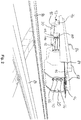
- the system 10 includes a plurality of track scanning sensors, which in this example comprise a plurality of imaging sensors 12.
- the imaging sensors are capable of recording electromagnetic radiation in the visible range, i.e. visible light, to show the external surface of a track object, but may additionally or alternatively encompass infrared wavelengths or wavelengths in the x-ray or terahertz spectrum to show the internal structure of a track object.
- An active light source for visible spectrum imaging or an energy projection and/or transmission device, shown schematically at 13, may be required for x-ray and terahertz imaging. In some examples of the invention, thermal imaging may also be accommodated.
- Both visible and thermal radiation wavelengths may be sensed at once by a common sensor and subsequently filtered to separate the visible and thermal/infrared images.
- different individual sensors may be mounted at one or more imaging sensor unit 12 with physical filters to control the wavelengths of radiation detected by each sensor.
- separate thermal/infrared (IR) and visible light images can be recorded.
- each imaging sensor comprises any or any combination of: whether it is color or monochrome; horizontal and vertical image resolution; scanning frequency in hertz; the type of interface with image acquisition devices including GIGE, CAMLINK, USB, etc.; sensor type and size; and, any inbuilt intelligence to perform analysis, data compression or dynamic adjustment of its imaging parameters to cater to changes in the environment.
- the sensors can be chosen to suit the environment for imaging on a mainline passenger, freight, metro, underground or dedicated inspection train, as well as on rail-adapted vehicles (e.g. hy-rail) and trolley-based platforms such that their imaging sensors can cover the overall area of survey and inspection as desired for a particular application.
- Each imaging sensor 12 in this example comprises a lens 14 and filter 16.
- the lenses 12 can be of fixed or variable focal length and define the field of view required for image capture.
- Appropriate cut-off filters 16 can be provided so as to limit the range of electromagnetic wavelength to which the sensor is exposed in use. This may reduce the external light interference from certain wavelengths.
- a central imaging sensor 12A is positioned generally about a rail 18 to be inspected in use, and two flanking imaging sensors 12B and 12C are positioned on either side thereof.
- the central sensor 12A provides an above view, i.e. a plan view, of a rail 18 in use, whereas the flanking 12B and 12C sensors are obliquely angled relative thereto and provide a view of the remainder of the track to each side of the rail.
- the angular offset between the sensors 12 is substantially in a common/vertical plane.
- the angular offset of the sensors 12B and 12C may be roughly 45° off the axis of alignment of sensor 12A, although the offset may be adjusted according to the field of view by virtue of lens 14 and so may encompass wider or narrower oblique angular offset.
- the number and position of sensors may be varied to cover the entire width of the track that needs to be inspected provided that the system mounting does not infringe required track and vehicle clearances.
- the fields of view of the sensors 12 may be overlapping to ensure full coverage.
- the arrangement of Fig. 1 is for scanning a single rail 18 including the flanking railroad track portions on either side of that rail, and that a further complement of sensors is provided for the adjacent rail. Only a single set of sensors is described for conciseness and it is assumed that the further set of sensors for the adjacent rail will match the sensors described in relation to Fig. 1 .
- the different fields of view collectively cover the entire width of the railroad track from one end of each sleeper to the opposing end. Thus imaging is performed for the track region on either side of the rails, e.g. with the option of sleeper ends, and not just the rails themselves.
- the imaging sensors 12 are digital scanners/cameras in the form of linescan sensors.
- areascan imaging sensors could be used in addition to, or instead of, the linescan sensors described above.
- a suitable imaging sensor 12 can be color or monochrome (grayscale).
- the field of view of the imaging sensors comprises the track directly beneath the system 10, i.e. beneath the railroad vehicle to which the system is mounted.
- the system has a top down view of the track.
- the internal imaging and laser sensors may be positioned top down or at an angle to cover the side of certain track assets such as rails and top track surfaces.
- the field of view of each sensor could be modified by altering the lens position 14 and/or its mounting position if required.
- the recorded track image is thus a digital representation of the light reflected from the various track components in the scene, having a pixel density according to the resolution of the imaging sensors being used.
- thermal imaging sensor which may comprise a suitable thermal camera or a thermopile array
- a digital image representing the heat sensed is recorded.
- the temperature values recorded are translated into an image representation that depicts the change in temperature across the scene, e.g. which could be output on a visual display to a human user, and is suitable for automated image analytics.
- the output of each of thermal and visible light sensors is therefore a sequence of images/frames, each comprising an ordered array of pixels covering the area of interest, each pixel having an associated color, brightness and/or heat energy (temperature) value.
- a digital image representing the amount of energy absorbed, reflected or transmitted through a track asset may be constructed as a linescan process or as an area image. Such an image will be able to show the internal structure of the target object, for example including internal cracks, voids and material condition for rails and sleepers
- the TrackVue system allows for adjustment the imaging sensor operation parameters, e.g. dynamically or through applied software control, such as aperture, exposure and gain settings in response to the amount of light detected by its internal sensor, thereby allowing for the recording of better quality images to compensate for any illumination changes over the imaged area.
- the system allows for adjustment of the sensor operation substantially in real time according to ambient changes in light levels by use of a suitable controller as will be described in further detail below.
- the TrackVue system 10 includes a dedicated light source for illuminating the region of the track being scanned. This may be achieved by continuous illumination of an area of the track that is in the imaging sensors 12 field of view or else by pulsing/flashing the light source only when an image is being captured.
- Fig. 1 illustrates the position of high intensity LED lights 22 that are suitable for this purpose.
- the lights may be split into modules that light the top of the rail and track, and side of rail areas.
- the lights are integrated within the overall system assembly housing 20 such that they are mounted relative to said housing 20 and are powered via the system as will be described below.
- the light source may be provided as one or more strips of individual lights, e.g. corresponding to the image captured from the linescan sensor.
- the lights can be selected for specific wavelengths or can be pure white so as to enhance the quality of imaged objects in digital images.
- the output of the light source is typically sufficient to provide the required lighting for operation in the absence of ambient/natural light.
- the sensor aperture, exposure and/or gain parameters may be used to substantially remove ambient effects on the sensor readings.
- it has been found that directional visible lighting onto certain track features may be desirable to determine asset identity and its condition.
- additional energy transmission sources may be necessary to generate x-ray or terahertz beams to bounce off or transmit through the target of interest that can be detected by an imaging sensor.
- the example of Fig. 1 comprises one or more laser device 24 for use in obtaining a further source of sensor data for use in surveying the railroad track.
- two laser devices 24 are provided for each rail 18.
- Each laser device 24 may be laterally offset from a central axis of the rail 18 and may be obliquely angled relative to vertical so as to image a side of the rail 18 as well as a portion of the rail head.
- a suitable laser scanning system may comprise either a laser emitting device 24 on its own, or a laser device 24 having its own imaging/scanning sensor assembly.
- the laser-sensor data acquisition/processing components could be integrated with dedicated sensors within the laser device 24 itself, in a separate dedicated unit, or could be comprised within track imaging sensors 12 as shown in Fig 1 .
- the laser emitting device 24 i.e. the laserhead
- the overall system housing 20 is powered thereby.
- a linear/beam laser may be used for geometric assessment of track components.
- a variety of laser beam patterns may be used including spot, line, and grid.
- the laser device may have an inbuilt processor or an external processor may be used to determine a three dimensional surface profile, which may be further combined with vehicle inertial data to determine the three dimensional positions of various track assets and/or three dimensional distances between two points in the scan area.
- Each laser device 24 emits a narrow beam of laser on the object of interest for surface topology measurement.
- the laser thus forms a region of irradiation, i.e. a linear path or a region across the rail and the adjacent track components, the reflection of which is detected by the corresponding sensor so as to interpret the corresponding geometry of the reflecting surface(s).
- a linear section or a wider area of the rail and any adjacent track components can be scanned, depending on the laser system implemented.
- the length, width and orientation of the laser beam pattern can be modified to suit specific applications.
- the power of the laser is optimised to generate a beam pattern that shows sufficient contrast between where it falls on the track, and its immediate surrounding areas.
- the imaging sensors used for laser beam imaging can be configured to generate coordinate data for the beam position within a field of view, e.g. binary data comprising horizontal (x), vertical (y) and depth (z), and/or generate a two dimensional grayscale image showing the laser beam against its surroundings which provides a reference to the identity of the object under measurement.
- a grayscale image requires further processing to generate depth data for each point on the laser beam within the image with supplementary processing of background image to understand the identity of assets overlaid by the laser beam.
- Dedicated laser imaging sensors for use with devices 24 could use area scan imaging at high frame rates and can be pulsed along with lasers. Pulsing as an option can be set in control circuitry either contained within assembly or a further control unit for the system as will be described below. Pulsing may serve to reduce laser emission, reduce overall power consumption and keep the lasers cooler than possible with constant emission.
- the scanning of railroad track may accommodate any, or any combination, of visible light (camera), x-ray or terahertz imaging camera and energy transmitter source, depth (e.g. laser) and/or thermal scanning sensors, any of which may output surface or subsurface image or surface profile/coordinate data to be used in the surveying system.
- depth e.g. laser
- thermal scanning sensors any of which may output surface or subsurface image or surface profile/coordinate data to be used in the surveying system.
- individual sensors or sensor types will be selectively operable, such that not all sensors are required to be operable at all times.
- One or more sensor may be triggered for operation at only selected times, or for only certain types of asset inspection, whilst one or more other sensor may be always used.
- the system is designed such that the laser light source, LED light source and energy transmitter does not contaminate the readings taken by the other sensors.
- Fig. 1 there is also shown an example of the image processing and ancillary equipment for operation of the track surveying system, mounted within common housing 20.
- the overall system is broadly split into three separate compartments/modules that are provided together a single unit for installation on a train. These are: (a) The main housing 20 of the TrackVue enclosure that houses sensors, lighting and other ancillary components; (b) A removable processing unit (RPU) 30 that is mechanically and electrically coupled to/within the main housing 20 for use and consists of data processing, storage and control hardware; (c) A battery 28 that also integrates with the main housing 20 to allow for system operation in addition to the use of power supplied via the railroad vehicle.
- RPU removable processing unit
- the main housing 20 defines a hollow enclosure to which any of the aforementioned scanning equipment 12A, 12B, 12C, 24 and any associated lighting 22 can be mounted. Corresponding openings/windows are provided in the housing 20 to allow imaging of the track components externally of the enclosure 20.
- the internal mounts for the scanning equipment within main housing enclosure may be adjustable, if needed, to allow for change in their viewing angles of the imaging sensors. Motorised/electrical angular adjustment mechanisms may be integrated into the camera/sensor mounts. This may be in addition to or instead of the sensor actuation equipment discussed in further detail below in relation to Fig. 2 .
- Each scan sensor and/or laser device 24 is typically placed behind a transparent window 26 which protects the sensor from the outside environment.
- the windows 26 are mounted in the wall of a common enclosure 20.
- a toughened glass or other suitably transparent material may be used for the window.
- the shape of the housing enclosure 20 in this example is such that it provides adequate clearance from the rail 18, whilst also offering the required field of view for each scan sensor. Therefore a contoured form for the housing 20 may be used as shown in Fig. 1 in which a central section of the housing wall (e.g. in the vicinity of the sensor 12A) is recessed relative to adjacent wall sections on each side thereof.
- the housing provides on its underside a central inverted gulley, which is aligned with a rail 18 in use, e.g. with two 'lobes' or downwardly protruding housing portions on either side thereof.
- the windows provided in the enclosure 20 may thus comprise window portions at different angular orientations to accommodate the different viewing angles of the different scanning sensors and/or the orientation of the enclosure wall where the window is located.
- a single cuboidal enclosure with no recessed contour that contains all required equipment may be used.
- Fig. 1 shows a single enclosure 20 containing all the sensors required for scanning of a single rail and the surrounding track components.
- the overall system may comprise two sets of scanning equipment/sensors in respect of two rails to be scanned simultaneously.
- the system may thus comprise two or more enclosures or housing structures for each set of equipment, which may be provided as a commonly mounted structure to the railroad vehicle.
- the system could comprise a single enclosure spanning both rails.
- the ancillary equipment shown in Fig. 1 may all be accommodated in a single enclosure or split between a plurality of enclosures sharing a common mount to the vehicle as necessary.
- the main housing 20 has a mount 32 for fixing the housing onto a railroad vehicle.
- the housing depends downwardly from an underside of a railroad vehicle and so upper wall 34 of the housing 20 has a mounting bracket 36 depending therefrom.
- the cooling of the interior of both the main housing 20 and also the RPU 30 is an important operational consideration for dissipation of heat generated by the imaging sensors, laser, LED lights, as well as any computational equipment.
- the exterior of TrackVue housing 20 will be air cooled by motion of the train in use and so conductive cooling of any heat sources can be accommodated by thermally coupling the heat sources to the external wall of the housing 20.
- the system may comprise one or more thermal management system/device 58, which may comprise of a liquid cooling system consisting of liquid reservoir, pumps and liquid blocks that can be mounted on components that need to be cooled.
- Fans, vents fins or the like may additionally or alternatively be provided on the housing 20, e.g. at location 38 in Fig. 1 .
- the thermal management system 35 may further comprise a heater that may be switched on by the control circuitry 42 when the enclosure temperature falls below freezing and is below the minimal operational temperature of the system components. The heater would warm up the reservoir fluid and circulate warm liquid to raise component temperatures in freezing conditions. In this manner, a common thermal management system may serve to ensure that the system can operate in both hot and cold conditions.
- One or more cooling fan 40 can be provided within either or both of the main enclosure 20 and RPU 30 so as to promote convection cooling. If necessary, either or both of the main enclosure or RPU 30 could be provided with a liquid cooling system in the event that air cooling is insufficient alone to maintain the internal temperature at a desired level.
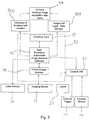
- the main housing further comprises control/management circuitry 42 which monitors trigger/pulse signals, power supply, devices within the TrackVue system 10 and any environmental readings.
- the management circuitry 42 is responsible for the operational state/health of the equipment and can output control signals to regulate their use so as to ensure equipment operation is maintained within desirable limits.
- the circuitry is responsible for managing a number of tasks including:
- the main housing 20 comprises a location determining device or module 54.
- This may comprise a standard GPS or Differential GPS device which records the latitude and longitude position of the vehicle, e.g. at a set frequency.
- the main housing 20 may comprise operational control devices, such as any, any combination, or all of:
- the main housing has electrical/data connectors for communication of data signals with the railroad vehicle and/or powering the TrackVue system 10.
- a minimum number of external connections may be provided to simplify installation of the system and may comprise a single power connector for the system 10 as a whole and a single external data connector port.
- a practical implementation of the system could comprise any, any combination, or all of:
- the system allows for the use of battery power for short surveys because of limited capacity, and uses power from the vehicle or mains power to charge it. As battery technology continues to develop, it is expected that longer surveys can be carried with battery power in the future.
- the current design allows for the battery 28 to be swapped easily from its own compartment in the field and replaced with a charged one to carry out recording.
- the battery charging and capacity status can be displayed on the LCD display 50 and also relayed to the operator console 44 ( Fig. 3 ).
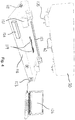
- the scan data processing equipment 72-78, associated software modules 79 and data storage 80 are housed within a separate RPU 30 housing.
- RPU 30 contains all computational equipment for data capture and processing.
- the RPU 30 comprises a self-contained unit which can process image data independently, provided it is supplied with the relevant incoming image data stream. For this reason, the RPU is provided within its own dedicated housing that is removable/replaceable as a module from the main housing 20.
- the RPU 30 in this example comprises computer motherboard 72, high speed processor 74, Field Programmable Gate Array (FPGA) or frame grabber 76, graphics card 78, and a non-volatile data store 80, e.g. comprising one or more data disks, on which are provided one or more software module for processing captured visual, thermal, laser, location and/or inertial sensor data.
- FPGA Field Programmable Gate Array
- the data store 80 also typically stores the track scan sensor data itself, location data and/or any processed track inspection (i.e. asset classification, defect and/or status) data.
- An internal battery 48 for the RPU 30 is provided to ensure that, as a minimum, the internal processing components can be gracefully shut down if the unit is disconnected from the main housing battery or external power supply. Ideally the internal battery 48 would also allow continued data processing, i.e. for image processing jobs already commenced, even if disconnected from external power.
- the internal battery may also power a communications module for transmission of any relevant messages/data prior to shut down.
- the battery may power the entire system for a period of time. As battery technology improves, inspections may be performed entirely under battery power.
- the RPU 30 has its own communication module 82, typically comprising and a conventional wired or wireless transceiver.
- the module may allow communications to the vehicle operator in an attended mode of operation, or otherwise to an Operational Command Centre (OCC) in unattended mode.
- OCC Operational Command Centre
- Such a communications module could additionally or alternatively be provided in the main housing 20 outside of the RPU.
- the data related to analysis or alerts can also be sent by this unit to the Train Information Management System (TIMS).
- a 3G/4G wireless data connection device 84 in the main housing 20 allows external access to TrackVue.
- device 84 may also be possible to put device 84 for wireless data transmission outside of the main housing 20, or elsewhere on the railway vehicle, if it improves data transmission especially if the length of cable between the device 84 and its antenna on the train is long and attenuates transmission signal strength.
- the wireless connection can also be used for remote access to perform diagnostics, software updates, and repairs of the unit.
- the communication module 82 may serve as an alert transmission unit for sending any alerts due to an adverse track or equipment status detected by either the control circuitry 42 or by the processing equipment within the RPU 30, to a remote location either using wireless or wired connection.
- the alert may relate to the condition of the system 10 itself, or the track being surveyed.
- the RPU 30 may also comprise any of a fan 40 for cooling the unit, thermal management device 58 and/or dehumidification device 60 for absorbing unwanted moisture in the internal compartment.
- the RPU 30 can be liquid cooled/heated by using blindmate liquid connectors from the system 38.
- the RPU uses blindmate connectors 62 to attach to the main housing 20 of TrackVue body. This allows the RPU to be detached from the TrackVue as required by the operator and can be taken to a back an office environment for data processing as will be described below.
- the RPU itself forms a completely sealed assembly for outdoor use.
- the RPU may have a handle (not shown) to aid removal. Status information related to RPU 30 or messages from control circuitry can be displayed directly on a touch panel display 50 which is visible to a human operator when inspecting the system.
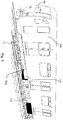
- Fig. 2 shows an example of a mounting system for TrackVue 10 in which a pair of housing enclosures 20 are mounted to a common support structure 84.
- a single housing enclosure may be mounted to the vehicle.
- the support structure 84 of Fig. 2 may be used instead of the fixed mount 32 described above in relation to Fig. 1 .
- the support structure 84 extends laterally relative to the rails 86 in use such that the relevant sensors can be held in relation to each rail.
- the support structure 84 comprises mounting members 88, e.g. so as to define a mounting frame structure for the system 10 as a whole, which attaches to a vehicle in use. Multiple mounting points may be defined on the frame and/or members 88 which can be attached to corresponding mounting points on the vehicle (not shown) using conventional fasteners, such as bolts.
- the members 88 take the form of elongate beams so as to provide strength to the mounting structure and also a common support to ensure the correct spacing between the scanning sensors for each rail 86.
- the mount comprises a panel member 89 having a frontal lip or wall section 90 in front of housing(s) 20.
- Fig. 2 also shows the data connectors 64, 70 and power connector 66 discussed above for operation of the TrackVue system 10.
- the field of view of a scanning sensor contained within the housing 20 depends on the position of mounting of the housing 20 on the vehicle, the position and orientation of the sensor within the housing 20, and the properties of its lens.
- the field of view of the sensor With reference to a fixed position on the track, such as the position of the rail, can change because of track curvature and lateral movement of the vehicle on the rails.
- the amount of change to the field of view of a sensor depends also on its distance from the vehicle wheel set. If the track curvature does not cause for the rail components of interest to significantly go out of the field of view, the scan data analysis software 79 ( Fig. 1 ) will be capable of their accurate detection and measurement. However for much higher track curvature, the sensor field of view could lose sight of assets of interest.
- One option to mitigate this would be mount the/each housing 20 as close to a vehicle wheel as possible, e.g. either on the bogie or close to it.
- each sensor could be individually actuable to keep the relevant track components within the field of view, e.g. by actuation of a lens or viewing aperture to widen/narrow the field of view or else using electro-mechanical actuators to adjust the orientation of the scanning sensors. Additionally or alternatively, the sensors' field of view could be adjusted collectively as discussed below.
- the mounting system 84 comprises an actuation unit 92 for the TrackVue system 10 as a whole.
- the actuation unit 92 is referred to herein as the 'TrackGlide' unit as shown in Fig. 2 .
- the mounting system 84 comprises one or more runner 94, via which the housing 20 is supported, e.g. suspended, in use.
- the housing 20 may comprise a bearing structure 95 for mounting on each runner 94 to allow low-friction movement along the runner.
- the runners 94 extend laterally relative to the track 86, e.g. being aligned with mounting members 88 and allow the housing 20 to be actuated in a constrained, linear manner as a moving platform so as to remain correctly positioned relative to the rails 86.
- the actuation unit 92 comprises one or more linear actuators 96 that attach to support 98, which may comprise a linear support. Controlled actuation is achieved using a suitable electrically-powered drive, such as a stepper motor, by way of an encoder 100.
- the actuation unit has an electrical connector 102 for powering the unit and a data connector 104 for receiving operation commands from an external source such as the TrackVue system 10, e.g. to control the distance and direction of movement of the overall TrackGlide unit 92.
- the electrical signal to control movement is generated by the control unit 42 ( Fig. 1 ) under the direction of software 56 which uses one or more scanning sensor (e.g. a laser sensor input and/or a digital image input) to decide on the position of a key reference feature/point on track, such as an edge of the rail.
- the control unit 42 uses the location of the reference feature to estimate the lateral movement of the vehicle relative to the track that must be compensated by moving the TrackGlide unit 92 ( Fig. 2 ) in the opposite direction.
- One or more inertia sensor could be used as an input to the control unit 42 in other examples of the TrackGlide system.
- the TrackVue housing 20 can thus be moved using the TrackGlide unit 92 in real-time, laterally, perpendicular to the direction of the running rail 86, e.g. by the same magnitude as any detected lateral vehicle motion but in opposite direction. This ensures that the TrackVue scanning sensors are at all times in the same relative position to the track as required to keep substantially the same relative field of view of the track.
- the mounting structure 84 including the mounting members 88 and/or panel 89 could be used but without the TrackGlide unit 92 so as to define a static support structure.
- a static support structure and/or housing could be used for mounting the overall system to the railway vehicle but the actuation unit/system could actuate the relevant sensors, e.g. as well as any associated lighting, relative thereto.
- the actuation unit/system could actuate the relevant sensors, e.g. as well as any associated lighting, relative thereto.
- the actuation system may be mounted within the outer housing.
- a single actuator could actuate all of the imaging sensors or just some of the sensors, for example with a plurality of actuators being used to move different sets of sensors either independently or in unison.
- a static or rigidly mounted housing and the track scanning sensors are mounted to an acutable support within the housing.
- the sensors may move relative to a window in the housing.
- the actuator and/or a suitable linear track or runner may be mounted within the housing.
- the RPU 30 processes either image or laser based data to determine the position of the rail and commands the linear actuator to follow the rail position as the vehicle moves at high speed by giving it data on the direction and amount of movement required.
- Fig. 3 shows an example of a passenger train 46, to which the TrackVue system 10 may be mounted using any of the mounting options described herein.
- the TrackVue system 10 is typically mounted on the underside of the rolling stock, for example on or adjacent a bogie 106 or between spaced bogies 106 of the rolling stock.
- a power converter 110 typically a DC to DC power converter
- Fig. 3 can be placed anywhere on the vehicle within a reasonable distance of the system, if required, and should provide uninterrupted power at 24VDC or a desired voltage level via power connector 66 ( Fig. 1 ).
- the output of vehicle speed sensor on board the train 46 is used by the TrackVue system 10 in a manner to be described below.
- a vehicle wheel tachometer 112 is used to correlate travel speed by the rate of vehicle wheel rotation, although a laser Doppler velocimetry device could equally be used.
- the signal output is preferably a pulse signal provided at a pulse frequency according to the speed of revolution of the vehicle wheel. Typically multiple pulses are provided per wheel revolution.
- Other suitable vehicle speed indicators could be used provided they provide precise and substantially instantaneous output at a resolution suitable for use as a trigger signal for the track scanning sensors.
- the vehicle 46 may comprise a location determination system, e.g. combined with inertial measurement system 54, which may communicate a current location with the TrackVue system 10, e.g. in addition to or instead of the location determining system within housing 20.
- the vehicle location determination system could comprise a conventional two-dimensional location system, e.g. a GPS system or the like for determining latitude and longitude. In other examples, the location determination system could determine location as a measure of distance along the track from one or more known track locations.
- the location determination system could comprise a vehicle travel distance sensor, such as the tachometer 112, and/or a track position sensor. This may be used in addition to, or instead of, a GPS location system. Combining multiple location determination systems/sensor types may be used to increase the accuracy of asset location determination.
- the data from the tachometer and GPS may be combined to determine track curvature.
- a track position sensor may comprise a sensor for identifying track features indicative of known/predetermined track locations, e.g. fixed datum locations.
- a scanning sensor 12, 24 ( Fig. 1 ) of the kind described above could be used for this purpose or else a near-field wireless communication transmitter/receiver 114 could be employed as shown in Fig. 3 .
- An RFID scanner mounted on the train or as part of the commonly mounted system 10 could be used to detect RFID tags mounted on the track at known locations.
- a lookup table of known tag locations may be used to determine asset and/or image sensor location.
- the operation of the TrackVue system in performing a track survey is described below.
- the sealed nature of the housing 20 and the dedicated light sources 22 ( Fig. 1 ) allow the TrackVue system to be used for rail inspection at any time of day/night and in varying weather conditions.
- the RPU 30 allows two forms of data processing. Firstly, real-time data analysis which uses a combination of either high speed processor 74 coupled with FPGA 76 and/or graphics card 78 to process image/pixel data and/or numerical/point data generated by the laser imaging device. In such analysis, logged imaging results are instant and there is no growing queue of data to process in a buffer. The FPGA and processor are selected to handle the expected volume and speed of incoming data (e.g. without requiring use of a buffer). Secondly, near real-time data analysis is possible using a library of software for high speed processor 74 and/or graphics card 78. Under these circumstances, the analysis is quick but may not be real-time and a buffer of unprocessed sensor data may build up over time depending on the type of analysis being undertaken.
- Near real-time analysis can be continued after all data acquisition has finished by either keeping the RPU 30 attached to the main TrackVue body 20 on the vehicle 46, or by detaching it and later attaching it to its docking station at a separate location, e.g. back office, as will be described below. Additionally, the data connections of the RPU 30 or housing 20 could be used to offload logged image data in a format suitable for subsequent processing.
- the linescan sensor captures a line on the track at a desired resolution and the TrackVue system builds up an image of the track or a section thereof by concatenating the lines together.
- the imaging resolution in pixel per millimetre in the direction of travel is a pre-set value, for example 0.5mm per pixel, which may be user specified/altered as required. For an imaging sensor to achieve this, it must be fast enough to accommodate the relevant train speed.
- the imaging resolution in the direction perpendicular to the direction of travel is based on the lens field of view. For example, if an image width is 1000mm and 2048 pixels represent it, it equates to 0.48 pixels/mm.
- the entire track image data can be constructed as a single image from the linescan output. However it is typical to divide the aggregated image data into smaller images, e.g. with the size of each division being decided based on a predetermined number of line scans, distance covered and/or image file size. In this example, a line scan count is maintained and a single image is defined every 2048 or 4096 line scans.
- the width of the image in pixels is determined by the imaging sensor capability and may be in excess of 1000 pixels, such as typically 2048 pixels or 4096 pixels, although different resolutions may be used for different requirements.
- the frequency of image (line, area or volume) capture may be controlled so as to be constant with respect to the distance travelled along the railroad.
- the frequency or resolution over a length of track may be fixed.
- the frequency of image capture or scanning is controlled based on the vehicle speed. In the present examples, this is achieved by use of the vehicle wheel tachometer 112, as shown in Fig. 3 , to provide a data capture regulation input, although in other examples a similar control scheme could be implemented using any other conventional vehicle speed sensor or odometer.
- a pulse signal is output to the relevant image capture device to initiate an instance of image capture, e.g. as a frame/area, line or region scan. Therefore, if the train accelerates, the relevant sensor(s) will scan more quickly, and if the train decelerates, the scanning rate is lowered accordingly.
- the operation of multiple imaging sensors, including digital cameras and/or laser sensors, can be synchronised such that they each trigger their data sampling at the same time. The raw data for different sensors at a common time/location can thus be cross-referenced within the indexed data store record.
- the wheel tachometer 112 ( Fig. 3 ) provides a fixed number of pulse signals to the TrackVue connector/interface 64 ( Fig. 1 ) for every wheel rotation thereby providing data on overall distance travelled, and speed of wheel rotation.
- the number of pulse signals is specified in terms of a fixed value per rotation.
- the wheel tachometer 112 pulse output rate is selected to work for a given maximum vehicle speed at a desired level of image resolution, e.g. such that the maximum scan rate is within the upper limit of the scanning sensors 12.
- TrackVue architecture is independent of the choice of the tachometer or speed sensor and can receive any suitable pulsed or other frequency control signal at interface 64.
- both wheel tachos fixed to the wheel or portable versions using laser Doppler can work as they provide a trigger in a suitable format, such as transistor-transistor logic or low voltage differential signalling format.
- Fig. 5 details the overall data flow process (including the flow of control signals and track inspection data outputs) from sensor 12, 24 outputs to the alerts/reporting tools for the end-user being displayed on an end user device 44 ( Fig. 3 ), including the scan/image data processing stages to analyse track components.
- Like reference numerals are used to depict like features described above in relation to Figs. 1-3 . Any, any combination, or all of the process stages may be automated in accordance with examples of the invention.
- the use of modular software 79 ( Fig. 1 ) and/or hardware 72-78 allows the data processing to be segmented into a plurality of tasks or 'levels', having the benefit that one or more level can be prioritised or handled separately from one or more further level.
- the image 12 and/or laser 24 sensors record data which is passed on to the main scan data processor 74 on-board TrackVue, comprising one or more high speed processor.
- the sensor data output may connect directly to the main processor 74 if no image compression is desired.
- real-time compression e.g. to JPEG format
- the data flows from imaging sensors to one or more FPGA or image grabbers, 76 which compress and reduce the quantity of data whist retaining the maximum possible image quality for further examination.
- the camera may itself compress the image data.
- the FPGA 76 also serves as the hardware used for real-time scan data analysis and would work together with the main processor 74 to load appropriate image analysis software 79 for analysing scan data.
- the number of input connections on an FPGA 76 may be limited and therefore if several imaging sensors need to be connected then more than one FPGA board may be employed.
- the main image processor 74 can also use an array of graphics cards 78 to process image data using real-time or near real-time data analysis, or simply store it in memory for analysis at a later time.
- the raw data is passed from the sensors to system memory for storage in parallel to sending it for processing.
- graphics cards allow the main processor to spread the load of image analysis on multiple parallel cores significantly reducing the time to process image data.
- the data for laser image acquisition is handled in exactly the same manner as image data unless the laser device 24 ( Fig. 1 ) has an internal data processing capability, in which case data from it is directly passed to the main processor 74 bypassing FPGA 76 and/or graphics card 78.
- the overall system of processing uses multiple software modules.
- the main processor 74 decides which software algorithm must be used for which sensor data from a pool of algorithms available within the data store.
- the implementation of the software algorithms is different for different hardware, for example, whether they need to be executed on a graphics card or FPGA.
- a software module or routine is a self-contained software tool which can take an image frame (typically in data format as a matrix of numbers) or laser data (as a one, two or three dimensional matrix of numbers), and apply a series of arithmetic operations to process either the contents the incoming data represents, or to make measurements within such data.
- a first software tool is for image and laser sensor data acquisition and controls the process of acquiring data including data flow from sensors, compression, sending it for analysis, recording it with a location (and optionally a timestamp) and storage on the physical hard disk 80 as a scan database 80B.
- All raw data needs to be stored to a physical memory 80A in addition to presenting it for analysis to appropriate processing hardware.
- a physical memory 80A For high speed data acquisition, storing JPEG images in real-time may be time consuming and therefore pixel data will be stored in a flat file structure which can be converted later into JPEG data by adding header information to it.
- Laser scan data in compressed format are also stored in the non-volatile data store 80.
- the location for storage in terms of data directory can be specified by the system operator.
- the system maintains a database record 80B in the data store 80 that stores for each raw data image collected, its location including GPS latitude and longitude coordinates and/or a railroad line reference position. In cases where RFID location data is available, this will be stored in addition to, or instead of, other location data.
- a second software tool is for image and laser sensor data analysis and is responsible for executing a number of processing routines/algorithms on the collected data in either real or near real-time. If on-board data analysis option is not chosen, no data analysis is performed while data is collected. All data analysis in such cases is performed offline in a back office environment. For such cases, an FPGA can be replaced with a simpler frame grabber board which can only acquire data but cannot process it.
- the first stage of data analysis identifies the contents of interest within an image, e.g. identifying one or more data features that may be indicative of its contents.
- a matrix of numbers representing an image record for each position/pixel within the image either a single value denoting the brightness of that pixel, or three numbers representing the red, green and blue channel color values for that pixel.
- One or more arithmetic operation is used to cluster pixels of similar properties that are adjacent to each other, e.g. according to an image segmentation process.
- the image is thus broken down into a series of clusters by assigning pixels to clusters according to brightness/colour and proximity to other pixels of the same/similar properties.
- a series of further operations are applied that determine one or more property for the cluster, thereby defining a feature of the cluster that may be indicative of a corresponding feature of an asset captured in the image.
- the cluster properties assessed at this stage may comprise any or any combination of a cluster edge, colour, texture, shape, pixel intensity and/or one or more other statistical property.
- a general assumption is made that all pixels clustered together represent the same object/component given their visual similarity.
- the process keeps track of which pixels (intensity value and coordinate positions within the image) belong to which cluster.
- a pixel can only belong to one cluster at a given time.
- the identified properties of each cluster can be used by a classifier (e.g. a software tool that classifies or recognises the identity of objects in image data based on what it has been trained to recognise).
- a classifier e.g. a software tool that classifies or recognises the identity of objects in image data based on what it has been trained to recognise.
- classification of each pixel cluster is used to classify the track components represented by the clusters.
- Feature analysis and track component classification can be performed by separate modules.
- the classification process/module matches the properties of each cluster to those of known objects (e.g. rail or sleeper). This process is known as feature based matching. In some cases, an image template of the known object may be matched or correlated against the cluster of pixels directly. This process is known as template matching. With either form of matching (feature or template based), if the level of match is greater than a pre-set threshold, the cluster is labelled to be the same as the object matched.
- Unmatched clusters are assigned to be a part of the background.
- the system stores a database record 80B in the data store 80 comprising any, or any combination of: the image sequence number where the object was found; a time stamp and/or location record of where the object was imaged on the track; an object label; object properties within the image (e.g. any or any combination of information on its centroid coordinates within the image, dimensions horizontal and vertical, coordinates of points of interest or boundary pixels, colour, edge and/or texture and/or shape data), position of the object relative to track centreline or running rail (field side or gauge side) and its depth profile. Further information may be stored about whether the detected asset has any defects or not, the nature of those defects, corresponding measurements and an indication of whether they are surface or subsurface.
- the system allows logging of a confidence score or rating in the relevant database in the data store 80, e.g. at 80B.
- a numerical assessment of the similarity between the imaged component and the predetermined component features or template feeds into a confidence score represented as a value on a defined scale, e.g. between 0 and 100, whereby 0 represents no confidence and 100 represents highest possible confidence.
- the confidence estimate is directly based on the level of match determined between the properties of a pixel cluster in the image, and of those of known objects, and takes into account the visibility of the object (e.g. excess ballast estimates around recognised objects provide a measure of visibility of objects).
- the image analysis process follows a hierarchical approach.
- key reference assets are recognised (see Figs. 6 and 7 ) including rail top 201, rail side 202, rail foot 203, ballast 204, sleeper 205, slab track 206, plates 232, switch 217 and third/electrified rail 41.
- a second stage processes pixel data from a smaller image area of interest comprising the image area covered by reference objects identified in the first stage and their surrounds. This is aimed at further identifying smaller objects of interest (e.g. spikes, or fasteners) which are then labelled as before.
- smaller objects of interest e.g. spikes, or fasteners
- each reference object and the further objects are thereafter analysed for defects.
- the condition/defect analysis may comprise one or a plurality of dedicated software modules.
- the tool will compare the amassed image data for the identified object against a predetermined (i.e. a nominal or previously recorded) object model.
- the precise details of the model and/or the comparison undertaken will typically differ between different track component types. In certain respects, this may be similar to the feature/template matching process described above, except that now that the component type is known, the differences between the imaged object and the predetermined model can be extracted and/or quantified to provide an account of the track component status.
- a comparison may be made between geometric attributes of the predetermined and scanned components, for example such as the component orientation, e.g. angular orientation or relative position, or one or more component dimension. Comparison may be made additionally or alternatively between surface properties (texture, colour) of the predetermined and measured components, e.g. including continuity/discontinuity of the surface.
- geometric attributes of the predetermined and scanned components for example such as the component orientation, e.g. angular orientation or relative position, or one or more component dimension.
- Comparison may be made additionally or alternatively between surface properties (texture, colour) of the predetermined and measured components, e.g. including continuity/discontinuity of the surface.
- the geometric and/or surface condition of an object can be analysed according to the present invention for detecting: (a) Wear and tear of the component; (b) Broken components; (c) Change in orientation of a component or part thereof, indicating damage; (d) Missing components if prior information is available on what components are expected on a given portion of track; and (e) Components obstructed from view because of snow, mud, leaves or sand thereon.
- Imaging sensors can evaluate component condition based on its visual appearance, change in colour, presence of edges which can represent cracks, change in object boundary orientation and so on. It is additionally or alternatively possible for inspection systems according to the invention to identify branding or product identification features in the surface of a track component.
- the system may be able to assess make, age and/or product ID of components automatically.
- the system may recognise this information by either performing optical character recognition on component surface writing or by detecting unique landmarks that provide metadata related to the component.
- the system can report on the presence or absence of a component defect. Once detected, it is also possible to determine further characteristics for known of identifiable defect types, such as: defect classification (type of defect, name); defect severity (a grade value); defect properties (size, shape, colour, orientation and so on); and/or defect change (measurements showing change in properties over time).
- defect classification type of defect, name
- defect severity a grade value
- defect properties size, shape, colour, orientation and so on
- defect change measures showing change in properties over time.
- a simple example may be a crack, the length and width of which may be tracked over repeated scans as the crack propagates over time. Similar techniques may apply to the dislodging or warping of components over time but may equally apply to instantaneous defects that can be compared to previous scan results or known defect types.
- identifiable defects can be either caused by poor rail wheel interaction (rail wear 221, squats and wheelburns 223, switch defects 218, running band deviation 222), excessive stress on track components causing fracture or components to break away (gauge corner cracking 220, cracks on rail 224, cracks on fishplate 225, breaks 233 and cracks 235 on sleepers 205, abnormal rail joint gaps 207, missing bolts on fishplates 211, missing fasteners 212, , rail discontinuity/break 219, missing spikes 227, raised spikes 228, missing anchors 230, base plate 232 movement either laterally or vertically, defects on electrified rail 41 b), temperature variations (abnormal expansion join gaps 208), and movement of the position of running rail or electrified rail 41 (electrified rail position with reference to running rail measurements 41 a).
- the defect sizes and severity data is stored in memory 80.
- the memory 80 also stores information on rail track assets (image objects) and defects (abnormalities within image objects) within a suitable cross-referencing database structure. For example, as shown in Fig. 5 separate entries are made for the analytical results at 80B and the sensor data storage itself at 80A. This can be achieved using separate tables within a common database or separate, cross-referenced databases to store location of image data on disk, identified assets and defects with their properties, and time and location information.
- a set of domain specific rules may applied on defect recognitions to rule out false positives. This can be applied as a post-process on the database table of defects 80B, or the scan analysis software 79 can apply this knowledge when identifying assets as part of the process described above.
- Laser scan data analysis may also be used independently to identify track components, features and/or defects, e.g. for components that are not readily perceivable using digital images or when a digital camera is unavailable. Laser scans provide valuable depth information which can represent certain defects on components. A sudden change in depth profile of one component may be normal for some, and abnormal in other cases.
- ballast/sleepers may be fairly normal, whereas, one does not expect the same on a railhead where it should be flagged as a defect.
- locations/points of curvature change in laser scanned surface profiles are measured which denote the edges of objects.
- the distance between two successive high curvature points is measured and evaluated for identity using a set of rules. For example, a raised segment with length close to 80mm represents the railhead provided another such segment can be identified at further a distance equal to the gauge of the track.
- proximity/distance between assets or track features can be used to classify the track components as being of a predetermined type.
- the evaluation of depth based surface profiles allows the detection and recognition of assets, and their three dimensional measurements or that of their defects. Additional inertial data is integrated into the analysis to provide a more accurate representation of track objects in three dimensional space from which data, various track geometry features such as track gauge, twist and super-elevation can be measured.
- Laser and image analysis processes share several common components. Each system's sampling rate can be controlled by vehicle speed using data from a shared wheel encoder 112 ( Fig. 3 ).
- the control unit 42 ( Fig. 1 ) ensures that the correct trigger and appropriate power is delivered to both imaging and laser components for operation.
- These systems also receive time and location information provided by the same external time sensors and location sensors.
- the level of sharing of data acquisition and processing devices such as FPGA, graphics cards, processor, disk memory and others depends on a chosen design and construction of the TrackVue system 10.
- linescan and laser data analysis can be completely independent.
- linescan data analysis information can be used to trigger a laser measurement or vice-versa.
- the data analytics from the laser and linescan data may be combined together for generating a better understanding of asset and its condition.
- the detection of plates 214 ( Fig. 6 ) in linescan imagery may detect a plate, which thereafter can trigger laser based measurement of plate 232 movement (e.g. laterally and/or vertically).
- laser and linescan measurements can be correlated so that one set of measurements confirms or discredits the presence of an object (e.g.
- the laser and linescan analysis can be cross referenced to provide additional context/meaning to laser measurements.
- Linescan analysis can provide details of object identity that lies under a projected laser beam such that measurements can be labelled and make sense.
- One or more laser data processing software module forms a part of the overall image analysis software 79 ( Fig. 1 ) and is responsible for object recognition and measurement.
- TrackVue 10 uses laser technology to make a number of such detections by evaluating the size, orientation and curvature of a laser beam pattern (line, spots or grid) within a 2D grayscale image.
- this technique can be used to determine (a) rail wear 221 on rail top 201 and rail side 202; (b) missing bolts on fishplates 211; (c) missing fasteners 212; (d) welds on rail foot 213; (e) plate depth movement 232 over the sleeper 205; (f) depth of railhead defects such as tamped joints 207, squats and wheelburns 223; (g) switch defects 218 ( Fig. 7 ); (h) the position of running rail with reference to the position of electrified rail 41 a; (i) measure gaps in electrified rail and abnormalities 41b; (j) unacceptable wear of electrified rail 41b.
- track components, sub-components and defects can be identified and assessed, including, in addition to the features described above: rail grind marks 237, welds 213, weld clamps 226, excess ballast 236, signalling assets 238, magnets 239, cables 240, wheelcut 234, present or missing fasteners such as spikes 215, and anchors 216.
- the processing steps described herein may be used to determine an amount of skew, misalignment or deformation for the measured component.
- Fig. 10 shows the position of laser line patterns on rail, plate and surrounding areas to make depth measurements as an illustrative example of how the laser beam pattern (a line in this case) can be projected across running rail features/components shown in Fig. 6 .
- the relative differences in orientation of the beam in sections B (over a sleeper 105) and C (over a plate 232) can provide details on vertical plate movement.
- Changes in beam straightness in section D (over rail foot 103) can provide data on the presence of fasteners 212 and welds 213.
- the corresponding curvature of beam between sections D (rail foot 103) and E (rail head 101) can provide data on rail wear 221.
- Beam straightness in section F can provide data on whether the beam is on a sleeper 205 (e.g. a smooth surface) or ballasted area 204 (e.g. an irregular surface).
- the orientation of laser beam projected axially along a rail itself shown as section GH can be used to determine the rail slope and identify defects such as dipped or spaced rail section joints 207.
- An optional laser beam A projected onto the railway vehicle wheel can provide further information for the measurement of the distance between the wheel flange and the edge of the rail. This can provide additional or alternative analysis of rail wheel interaction.
- the scans generated by the laser unit can be analysed using one or two dimensional data analysis, or by first building a three dimensional surface and then applying three dimensional data analysis algorithms for determining the geometry of components, and further estimating their identity based on dimension and shape measurements from such profiles.
- the profiles are subject to noise and without information typically associated with imaging sensors such as color and/or brightness/texture, the component recognition software for analysing laser data alone achieves limited success.
- the asset identification and status assessment algorithms have been found to achieve better accuracy on asset recognition by combining laser sensor data analysis with imaging sensor data analysis wherever possible.
- Thermal imaging sensors can also be used to identify and/or detect defects in track-related assets or components.
- Thermal images may be attained using digital images in the thermal/infra-red or near infra-red band of the electromagnetic spectrum. Taking of thermal images may be triggered in any of the ways described above for visual images and/or laser scans. The processing of thermal images may be less rigorous and may be used simply to identify the presence or absence of a heat source, e.g. as an elevated temperature region above ambient. Additionally or alternatively, thermal images may be processed in a manner akin to visual pixel image data in order to identify pixel clusters and associated features of components.
- Thermal images may be used independently to assess the presence/status of a component or in conjunction with the camera and/or laser scan data to improve the certainty with which components can be analysed.
- the absence of an expected heat signature may be used to indicate a defect, such as a broken cable or connection, which may or may not be identifiable in other scan data sources.
- X-ray and terahertz imaging allow the detection of internal flaws within certain track components.
- X-rays can be used to detect internal rail flaws
- terahertz imaging can be used to detect internal sleeper (tie) flaws.
- Rail based flaws may comprise of internal cracks or air gaps
- sleeper based flaws may comprise of internal rot, air gaps, excess water and breaks.
- the images would be analysed with asset status analyser to determine internal condition of rails and sleepers (ties) as well as other components within the sensor field of view.
- the system may also serve as a novelty/anomaly detector.
- the relevant processor 72-78 and/or software module 79 of Fig. 1 can output a finding of an unclassified object.
- the visual images and/or laser scan data in which the anomaly is present may be logged and an alert output identifying the presence of an anomaly, e.g. including its location. Manual input may be required to identify the asset type, if necessary to update the record after inspection.
- the data store 80 may comprise a database of known track component types, e.g. comprising a collection of pertinent component surface/color features, ranges of geometric values, edge features and/or other features such as temperature or surface texture.
- the captured scan data can thus be compared to any such predetermined features or associated numerical values when identifying components.
- the collection of predetermined feature values for known components may thus represent a computational model of a component type.
- FIG. 4 shows a user console or system by which imaging data stored by the RPU 30 can be analysed at a later time (offline processing) after data capture.
- the defect and system status data may also be transmitted by the cellular router 84 to a remote destination through which it is accessible using a web-portal. In this manner, the remote end-user is able to review data analysis in near or close to real time.
- the RPU 30 can be detached and used within a back office environment. It requires a docking station 116 within such an environment to receive power for continuing data analysis operations.
- the docking station 116 takes power from a mains supply via a suitable power connector 118 and converts it to power that can be used by the RPU 30 by using a suitable power converter. Correct docking is assisted through the use of guiding pins 120 which align into corresponding docking formations 121 in the station 116 for a secure mechanical and electrical connection. Other electromechanical connectors may be used.
- the power/data connectors 62 of the RPU 30 are received by corresponding connectors 119 in the docking station 116.
- a cooling unit 122 in the docking station 116 using either air/convention, conduction cooling or liquid cooling may be used.
- the docking station can be connected to a computer 124 which can access the RPU through it using a standard data connection, e.g. USB or Ethernet/RJ45 connector 123.
- the RPU can be connected to a local network for remote access through the relevant network connection.
- the docking station 116 may also have a power converter 126 to convert a conventional mains AC supply to a DC supply for powering the RPU 30.
- TrackVue can offer a compact and integrated solution to the detection and condition assessment of rail track components using surface and/or sub-surface data analysis and track geometry measurements whereby all sensor and processing equipment may be packaged inside a singular rugged assembly.
- the solution is designed for easy attachment to a range of vehicles, especially passenger and inspection trains, and is significantly more compact than conventional track surveying and inspection systems that use separate in-cabin and out-cabin equipment.
- TrackVue is designed for low power consumption, which is a critical enabler for use on passenger trains, by reducing the number of electrical components used, improving system design, and by selecting low power yet high performance components.
- the external dependencies for operation of TrackVue are significantly reduced compared to existing inspection train systems and can use wireless communication with an operator console 44 ( Fig. 3 ).
- the overall design therefore significantly reduces the cabling/installation burden as all connections between the camera and laser equipment, processing equipment and data storage are internal to TrackVue enclosure.
- the system can operate from low vehicle speeds of 1-5 miles per hour up to speeds of high speed trains, e.g. 220 miles per hour. At any such speeds, analysis of the track and associated components can be performed at relatively small increments in the direction of travel, such as for example at 10 cm or smaller.
- TrackVue can work in both " attended " and " unattended “ mode.
- the operator starts track surveying and inspection process by powering on the system through a console application which allows them to change any settings if needed before the start, otherwise, default settings apply.
- any alerts are fed back to the operator on their console 44 ( Fig. 3 ) through a desktop application which provides real-time display of images and/or statistics on surveyed track.
- any assets detected are presented to the operator and can be overlaid on a map or other on-screen visual track representation.
- a pool of image/laser data waiting to be processed is maintained and recorded in database.
- the position of the vehicle using one or more location sensors can be displayed for all track components and/or data collected.
- One, two or three-dimensional plans of the surveyed route can be generated using the surveying system described herein, in which the track and relative locations of identified components/defects are marked.
- At least one wireless or a wired connection is established between the system enclosure and the console 44 mounted inside the vehicle for operator inspection and/or use. This can transmit in real-time information on raw data, track components, their condition, measurements, and system status to the operator which can be displayed on the console 44.
- a reporting tool allows for a range of asset survey reports and graphs to be generated.
- the format of reports and graphs is optimised for the end-user. Any problems associated with TrackVue performance or malfunction is displayed for correction at the operator console.
- the console also displays the current status of data analysis. If real-time analysis is chosen, all analysis is finished at the time of the end of the current run. In case of near real-time analysis, the console shows the amount of data waiting to be processed. At this stage, the operator has the option of continuing on with the analysis, or to stop the analysis. Any unfinished analysis can be carried out the next time TrackVue is started or by removal of the RPU and attachment to a power source, e.g.
- the RPU serves as a replacement for data analysis in a back office environment.
- the results can be offloaded from it through a USB connection by copying track imagery and results database, or by simply removing a detachable disk.
- a separate offline desktop software can be used by end-users in an office environment to perform a number of tasks including: (i) Reviewing of detected track components and their condition using rail route maps or other GIS maps where available, and applying tools for eliminating any false detections; (ii) Generation of survey reports for maintenance detailing track components and their condition; (iii) Comparison of analysis from multiple previous runs to see the changes in track condition; (iv) Generate a risk assessment report for identified track components; (v) Generate a labelled plan of the track; (vi) Generate a report detailing novel features on track, for example excess sand, mud or snow, or unusual objects; (vii) Print or export to portable devices various defect data, reports and any other statistics; (ix) Plan maintenance for short or long term strategic planning on equipment repairs or replacement; (x) Plan for any track renewals; (xi) Exporting analysis to a centralised Engineering Data Management System which contains a wider set of track condition information; (xii) Exporting analysis to any web-portals or external databases; (xiii
- the system starts automatically on receiving power from the external source.
- Data acquisition sensors and lighting units are triggered to start operation once data from the wheel tacho or other suitable signal input confirms that the vehicle is in motion. If the vehicle stops for a period greater than a pre-set threshold, the sensors stop recording.
- the system does not require a console to display data acquisition or defect analysis. Instead, the results are transmitted to the Train Information Management System (TIMS) directly, or through email/wireless communication to an external Operation control Centre (OCC). Any further actions taken on such communication is the responsibility of TIMS or CCC.
- a "near real-time" data analysis approach is employed on an unattended system, it is programmed to continue data processing as long as mains power or battery power is available and buffer data analysis for future runs if needed.
- the system can be used for a wide variety of tasks including track component recognition and registration, track condition monitoring, change and degradation detection, track risk evaluation, generating maps of track with assets/defects embedded within such a map, detection of novel and threat objects, and measurement of track/rail properties such as curvature.
- the invention may allow plotting the analysis results with the available location data to produce Geographical Information System (GIS) maps for print or export. By repeating the analysis at regular time intervals, changes in component conditions and the associated level of risk can be determined.
- GIS Geographical Information System
- the system can thus be used to generate risk reports on track sections which will contain information on track defect identity, position, and/or risk severity. Reports containing information obtained through use of the invention may be output by the system and used for planning any or any combination of track checks, maintenance, repair/renewal, removal and/or replacement.
Abstract
Description
- The present invention relates to apparatus for the surveying of railroad track, and more particularly, although not exclusively, apparatus for assessing track health based on inspection.
- Railroad tracks, also known as 'permanent way', consist of rails, fasteners, sleepers (ties), ballast and the underlying subgrade. A wide variety of variations are possible in terms of types of rail used, jointed or continuous welded, use of sleepers with ballast or slab track, type of fastenings used, and switch layouts. A number of associated track assets are also mounted on conventional railroad, such as equipment of signalling, lubrication, cabling and/or switch operation, amongst others. Over time, track components and assets degrade and endure damage because of the physical stress caused by movement of trains, changes in weather conditions causing compression or expansion in materials, rain and environmental conditions, and degradation in material strength with age.
- Railroad track inspection processes are aimed at finding missing and defective components so as to be able to carry out effective maintenance with the intent of repair or replacement. If the track and associated assets are not monitored effectively, then there is a risk of complete failure or degradation to the extent that a significant risk is posed to safe operation of the railroad.
- Human track inspectors have conventionally carried out the job of visual track inspection by walking along the railway track and taking notes on track condition which is later used to guide track maintenance activities. Such form of inspection is costly, unsafe, slow and prone to human error. Growth in rail networks, coupled with the time required for manual inspection has made it difficult in practice to carry out manual track inspection at the required inspection frequency with full network coverage.
- Over the last two decades, rail infrastructure operators have increasingly started to carry out track monitoring using dedicated "inspection trains". These trains are designed for hosting equipment for semi or fully automated track inspection equipment. Currently available systems of this kind use scanning equipment, including cameras and/or laser scanners, for monitoring various parts of the track. Implementation of the systems on inspection trains results in the various system components being distributed over a local network for the system, with sensing equipment being typically mounted on the vehicle exterior and data storage and control systems being mounted with a cabin interior, e.g. within suitable racks.
- The implementation and maintenance of such systems is costly, and time consuming. In particular, such systems need extensive configuration to fit to a given vehicle which increases the complexity of installation and future maintenance burden. Each inspection train thus requires customisation such that it is fit for purpose. The overall distributed architecture comprising hardware components both outside and inside the vehicle, high power consumption, and the permanent equipment fixtures arrangement means that inspection trains have developed with time as their own subtype of railway vehicle.
- However the cost of running inspection trains is burdensome. Not only due to the aforementioned installation and maintenance costs, but also because of the need to schedule inspection train journeys along busy railway lines. The running of inspection trains is to the potential detriment of the railway line capacity for passenger or freight vehicles, particularly considering the relatively low speeds at which conventional inspection trains gather data.
- The data produced by the track scanning process may be transferred to an off-site computer network, where it can be analysed. The requirement for data to be amassed and communicated to a central location for processing, coupled with the detailed processing of the recorded data, can lead to a significant delay between the inspection itself and the deduction of any action required based on the inspection. Furthermore it can be problematic handling the large volumes of scan data generated.
- It is an object of the present invention to provide a railroad track surveying system that overcomes or substantially mitigates one or more of the above disadvantages associated with the prior art. It may be considered an additional or alternative aim of the invention to provide a system that can provide useful track inspection results in a more convenient manner.
- According to an aspect of the invention there is provided a railroad track inspection system comprising: a plurality of track scanning sensors, a location determining system and/or an inertial data measurement sensor, a data store for storing track scan data recorded by the track scanning sensors, and a scan data processor for automatic analysis of said track scan data upon receipt thereof to detect one or more track components within the scan data from a predetermined list of component types according to one or more features identified in said scan data and to determine the condition of said one or more track component, wherein the system comprises a common support to which the track scanning sensors, the data store and scan data processor are attached, the common support having a mounting for attachment of the system to the exterior of a railway vehicle in use.
- The common support may allow attachment of the system to a railroad vehicle as a unit, e.g. as a single fixture or assembly. The common support may comprise a housing, e.g. a rigid enclosure for the internal system elements, such that the system can be mounted to the railroad vehicle in the form of an enclosed module. The system may be fitted to new railway vehicle or retrofitted to existing vehicles in a simple manner, for example allowing the system to be used on passenger or freight vehicles, as well as inspection trains and other vehicle types. A single customised support/housing structure allows the internal system to be optimised for scan data processing such that track analysis can be performed in, or close to, real time. The system may be portable and may be transferred from one vehicle to another vehicle by making modifications only to the exterior of the host vehicle.
- The common support and/or housing may comprise a power and/or data connector for the system, i.e. to allow electrical power supply to the system and/or data communication between the system and the railroad vehicle and/or another network. A common power and/or data connector for the whole system may be provided. The system may comprise a data transmitter and/or receiver.
- The scanning sensors may comprise one or more image capture sensor. The image capture sensor may comprise a light sensor, e.g. for capturing a visual image, such as a camera. One or more line scan sensor or area scan sensor may be used, Additionally or alternatively, the scanning sensors may comprise either or both of a laser scanner or thermal/infra-red image capture sensor.
- The system may comprise an active source for transmitting energy, e.g. in the visible, x-ray or terahertz spectrum, on or through the track, e.g. comprising one or more track object of interest. The track object can be imaged by an appropriate imaging sensor as the residual energy reflects off or transmits through the object which is detected by a sensor and converted into an image. The images may show the internal structure of the object of interest.
- The rigid enclosure may comprise a wall structure shaped so as to define a first portion arranged to be located above a rail of the railroad track in use and at least one further portion adjacent the first portion, the first portion facing the rail in use and being recessed with respect to the further portion.
- The common support and/or housing may comprise one or more window arranged in the field of view between one or more sensor and the track to be scanned in use. A plurality of window portions may be provided and may be arranged at different angular orientations, e.g. wherein at least one window portion is arranged at a different angular orientation to at least one further window portion. A plurality of window portions may be arranged at opposing angular, e.g. oblique, orientations. A central window portion may be arranged between the opposing window portions. The opposing window portions may be symmetrical about a central axis or plane, e.g. corresponding to the central axis of a rail in use.
- The scan processor and/or data store may be provided as a removable processing unit or module, which may be releasably coupled, e.g. mechanically and electrically, to the common support and/or housing for use. The removable processing unit may comprise an enclosure in which the scan processor and/or data store is housed. The enclosure may comprise a data and/or power connector for connection with a corresponding connector on the common support. The removable processing unit may comprise a battery and/or transmitter/receiver circuitry.
- The scan processor may construct, e.g. automatically, an image of a length or section of track from a plurality of scans from one or more of the scanning sensors. The scan processor may concatenate a plurality of images from a single sensor (e.g. using consecutive scans) or a plurality of sensors.
- The scan data may comprise digital image data, for example comprising pixel intensity values. The scan data may comprise a matrix of pixel data. The scan data may comprise a visual image and/or thermal image.
- The scan data processor may identify pixel clusters within an image according to one or more pixel property, such as brightness or colour. Pixel clusters may be used to determine edge, colour, texture, shape and/or other statistical properties for an asset. A pixel cluster may represent an object, such as a track component or part thereof.
- The one or more scan data feature may comprise a geometric and/or color feature. One or more shape/geometric feature of the track, or a component thereof, such as an edge or dimension, may be determined from one or more image capture sensor, e.g. according to colour and/or brightness/intensity within the captured data. Additionally or alternatively a geometric feature may be determined from a different scanning sensor such as a laser/distance sensor. A profile of a track component may be determined using a laser sensor, e.g. a profile of a rail.
- The plurality of scanning sensors may comprise a plurality of the same or different types of image capture sensor. Different sensor types may comprise sensors for different electromagnetic radiation types/wavelengths. Alternatively different scanning sensor types may comprise different sensor dimensionality or orientation, e.g. such as area scan, line scan, depth detection sensors, three-dimensional surface scanning/imaging and/or sensors that use active energy transmission through an object to image its internal features (e.g. in the x-ray and terahertz spectrum).
- Automatic track component classification and or status assessment may be beneficially improved by multiple track view analysis. The system may compare/contrast two-dimensional and three-dimensional scan data of one or more common track component in determining the component type and/or status.
- Surface profiling and depth measurement sensors such as lasers may be accompanied by inertial data measurement sensors to determine track properties such as its geometry through the measurement of rail superelevation, twist, track curvature, and gauge parameters. In addition, the depth measurement data may be used to measure rail wear on both top and side portions of the rail.
- Different sensor types may be used in parallel. For example, the output of each sensor may be used to detect/assess track components independently, e.g. using the same or a different type of assessment depending on sensor type. The scan data processor may receive the different sensor inputs and may use them in combination to determine a track component type and/or track component status. The combination of different modalities in this manner can provide greater certainty of automated track inspection, for example in which a finding using one modality is compared to a corresponding finding using another modality in order to confirm or reject that finding.
- The system may comprise a plurality of track scanning sensors for each rail under inspection. First and second sensors may or may not be positioned on either side of the rail, e.g. as flanking sensors. At least one sensor may be positioned, e.g. orthogonally or vertically, above each rail so as to provide a plan view of the rail head. At least one sensor may be laterally offset from the axis, e.g. on either side of the rail or a vertical axis/plane of the rail. Any laterally offset sensor is typically obliquely angled, e.g. relative to an axis/plane of the rail.
- The system may comprise first and second sets of sensors, each set of sensors being arranged to scan a single rail, wherein the common support comprises a common spacer or lateral support member to which each set of sensors is mounted, e.g. in a spaced arrangement and/or towards opposing ends of the common spacer. The common support may comprise a plurality of lateral beams.
- Any or any combination of the track scanning sensor(s) may be adjustably mounted to the common support, e.g. to adjust the field of view of the image capture sensor(s). The sensor mountings may be individually or commonly adjustable. Lateral movement of any or any combination of the scanning sensors may be accommodated. Additionally or alternatively angular adjustment and/or focal length adjustment may be used. Additionally or alternatively adjustment of a lens and/or aperture may be used to adjust (e.g. widen/reduce) the sensor field of view. An angular or focal adjustment mechanism may be provided for each sensor or sensor type, e.g. individually, whereas a lateral movement mechanism may be provided collectively for the system or the plurality of sensors as a whole.
- The track scanning sensors may comprise at least two track scanning sensors mounted at spaced positions relative to the common support structure and opposingly oriented so as to scan a common railroad track component from opposing sides in use.
- The common support may comprise an adjustable support structure, e.g. to allow adjustment of the position of the plurality of sensors and/or the system as a whole. The common support may allow position adjustment relative to the mounting. The common support may comprise a moveable portion, such as a moveable housing/enclosure, which is variably positionable relative to the mounting. The common support may allow common position adjustment for any combination or all of the plurality of scan sensors, e.g. to accommodate track curvature or the like.
- Common position adjustment for the scanning sensors in use may be limited to a single degree of freedom, e.g. lateral adjustment relative to the direction of the rail(s) under inspection, e.g. such that the sensors remain in the same relative position with respect to the rail irrespective of the vehicle speed and track curvature. Common position adjustment may be used to follow, i.e. dynamically, the direction of the railway track in use, e.g. by remaining aligned with one or both rail of the track.
- The common support may comprise at least one rail or runner. A housing for one or more scanning sensor, e.g. a common housing, may be mounted to the runner.
- The system may comprise an actuator for position adjustment relative to the mounting. The actuator may be arranged for linear/lateral actuation, e.g. by way of a linear actuator or a rotor comprising a mechanism for converting rotational/torque input to linear motion. The actuator may be electrically powered, such as an electro-mechanical actuator. The actuator may provide for the lateral adjustment of the imaging sensors to remain in the same relative position with respect to the rail whilst the vehicle is in motion.
- The common support may be adjustably mounted to accommodate height adjustment of the sensors and/or the system as a whole. Height adjustment may be implemented to attain a predetermined height above the track and/or a rail thereof. Height adjustment may be implemented dynamically during use of the sensors or may be set at a predetermined height prior to use. Height adjustment may allow alteration of the field of view of one or more scanning sensor. Height adjustment may be used to effect different modes of operation of the system, for example to include rail inspection or whole track inspection. Different heights may be suited to inspection of different specific track component types.
- The system may comprise a controller, e.g. mounted on the common support and/or within a common housing. The controller may control any or any combination of: the track scanning sensors; power management for the system, e.g. including charging of one or more battery; thermal management of the system; data communications to/from the system, e.g. including alerts; lighting or other irradiation of the track for the scanning sensors. The controller functionality may be provided by one or more processor. The scan data processor may perform some or all controller functionality or else a separate system controller may be provided.
- The rate of track scanning may be controlled according to the railroad vehicle travel speed. A predetermined rate of scan/image capture or volume of scan data per unit distance may be set. For example, a rate of pixel capture per mm distance along the track may be set. A pulsed signal at a pulse frequency according to vehicle speed may be used to control the scanning rate. Additionally or alternatively, the rate of track scanning may be altered according to user requirements and/or predetermined track sections, e.g. according to different modes of track scanning.
- A vehicle wheel or drive shaft tachometer may be used to determine travel distance/speed. A laser Doppler device may be used.
- The system may comprise an irradiation/light source. A dedicated light source mounted on the common support may provide bespoke illumination for the purpose of the invention, e.g. arranged to illuminate a region of the railroad track corresponding to the field of view of the track scanning sensors. A linear light source array (e.g. a linear array of LED's) may extend across the width of the common support and/or track in order to provide uniform lighting across the track section being scanned. Alternatively, light may be directed onto opposing sides of each rail of the railroad track.
- The light source may be operated in a discontinuous, e.g. pulsed or intermittent, manner. The light source may or may not be pulsed according to the scan frequency of one or more sensors and/or vehicle speed.
- One or more scan sensor may comprise a filter, e.g. a light filter. The filter may be adapted to prevent unwanted wavelengths within the scan data and may for example be tailored to a light source of the system. The operation of the system may adjust according to the level of the light received by the sensors. An aperture or filter of the/each scanning sensor may be adjustable, e.g. according to the ambient light level.
- The system may comprise of an energy transmission source that is required for imaging sensors operating within a suitable portion of the electromagnetic spectrum to image a target area. Sub 1 mm wavelength radiation may be used, such as x-ray or terahertz radiation. The transmission and energy characteristics could be configured to maximise the image contrast and ability to see the internal structure of the object. The energy transmitter may be synchronised with the imaging sensor such that the reflected or transmitted energy from an object of interest is imaged by the sensor, e.g. in either a linescan or area mode.
- The system may comprise a location determination device/system. The track scan data recorded by the sensors may be logged with a location record (e.g. a geographical location record) from the location determination system. The location record may correspond to the sensor/vehicle location. Where a plurality of sensors are used the corresponding scan data captured by the plurality of sensors may be logged with a common location record.
- The location record may comprise a plurality of components (e.g. latitude and longitude) according to a geographic coordinate system. The location record may additionally or alternatively comprise a local or relative coordinate value, e.g. relative to the railroad track. The location record may comprise a one-dimensional location record component or value, e.g. according to distance along the railroad from a datum point. In any examples, the location record may be supplemented with, or substituted for, a time record (e.g. a timestamp).
- The location determination system may comprise a vehicle travel distance sensor, such as a tachometer, and/or a track position sensor. This may be used in addition to, or instead of, a GPS or other geographic location system. Combining multiple location determination systems/sensor types may be used to increase the accuracy of track component location determination. A track position sensor may comprise a sensor for identifying track features indicative of known/predetermined track locations, e.g. fixed datum locations. One or more scanning sensor could be used for this purpose or else a near-field wireless communication transmitter receiver. An RFID sensor, for example, could be used to detect RFID tags mounted on the track at known locations. A lookup table of known tag locations may be used to determine asset and/or image sensor location.
- The inertial data sensor(s) may comprise any, or any combination, of: accelerometers, gyroscopes, inclinometers and other electromechanical systems to generate data on three dimensional position, velocity, acceleration, and roll, pitch, and heading. The inertial data combined together with satellite information on vehicle position, and with tacho data, provides enhanced accuracy on positioning of measurements including tunnels. It may be further combined with laser based measurements of rail and surrounding track to provide track geometry measurements in real time.
- The system may comprise a thermal management device, e.g. a cooling and/or heating device. A fan, peltier air cooler or liquid cooling system may be used. A common housing may comprise one or more vents to permit airflow through the housing interior.
- The system may comprise a local power source, such as a battery. The local power source may allow at least some, or all, functions of the system to operate in isolation of an external power connection. For example, the battery may allow processing of received scan data, e.g. in order to complete scan data analysis after power supplied by the railroad vehicle has been cut off. The local power source may be charged by vehicle motion, e.g. vibration and/or wheel motion.
- The scan data processor may comprise a plurality of processors/chips, wherein at least one processor is arranged to log captured scans/images and associated location data in real time in the data store. Said processor may be arranged to collate image/scan and/or associated data from a plurality of sensors/sources.
- At least one processor may be arranged to process the captured scan data to identify track components substantially in real-time or with a slight time delay, e.g. near-real time. At least one processor may be arranged to perform image analytics on images captured by the scan sensor(s). Scan data may be logged in parallel with analytical processing thereof. A central controller may determine which of the processes are carried out concurrently according to data input rate and/or processing rate. Any or any combination of the processors may operate automatically upon receipt of the relevant data.
- Scan data storage may comprise indexing scan data with a location and/or time data record. Scan data storage may comprise storing scan data as a flat (e.g. binary) pixel data format, or as compressed images with conventional formats such as JPEG, e.g. with a location identifier. For flat file format, scan data file header information may be added at a subsequent processing stage (e.g. not in real-time or near real-time).
- At least one scan data processor may be arranged to process the recorded scan data so as to analyse track component status either on board the common support structure, on board the railway vehicle, or else at a remote location, e.g. at a time after scan data acquisition. The system may output track component identification, location and/or status in real-time, e.g. such that there is substantially no delay or negligible delay between when the track components are visible within the field of view of the scanning sensors, and their detection by the automated scan data analysing system. This allows for the operator to view track component identification and/or status as the vehicle passes those components in real-time. The scan processor may output track component status either immediately or with a relatively short time delay after image capture, e.g. in near real-time. In any example of the invention the recorded scan data processing time may comprise a relatively shorter time period or speed compared to the travel time or speed of the vehicle, such as for example a fraction of the travel time/speed, e.g. less than a half or quarter of the vehicle travel time/speed, or an order of magnitude or more less than the vehicle travel time/speed, at normal vehicle speeds. In case of near real-time, there is a short delay between when the sensors are able to view a track component, and when it is registered as found with its measured properties within a database used by the scan data processor. This delay can be variable based on the hardware capability and complexity of scan data analysis software.
- The data store may comprise a non-volatile data store comprising a database comprising raw scan data obtained from the sensors and a further database comprising track component classification, track measurements and/or status data logged with a location record corresponding thereto.
- The data store may comprise a processed scan/image data store and a buffer. The processed scan data store may comprise scan image files and associated track component classification and/or status data. Real-time or immediate processing of data as referred to herein may occur at the rate of scan data acquisition, e.g. substantially avoiding use of the buffer. The processed scan/image data store may comprise location data corresponding to the stored images.
- The scan data processor may comprise a central processor and either or both of a field programmable gate array and a graphics card. The ability to divide up the processing between different processors is beneficial in defining a hierarchy of processing tasks.
- The scan data processor may comprise a sensor data collation/ management module and data analysis module. A more detailed data review module may be provided as part of the system but may be only selectively employed by a central processor. A modular approach to data processing may allow a different combination tasks to be performed selectively for different track assessment jobs. Not all tasks need be performed for all uses of the system. For example, some processing stages can take precedence and always be performed (e.g. in real time), such as scan data indexing, whilst one or more further data analysis stage may be optionally employed.
- Dimension and/or shape measurement of track components may be matched to predetermined shape profiles, e.g. in order to determine the identity of track components, measure them, identify their defects, identity missing components where expected, or trigger a further data analysis with another sensor. One, two or three dimensional shape model constructs and/or analysis may be used. Shape profiles may be further evaluated using their size, shape and orientation. Any such parameters may be used in combination with inertial data to determine rail orientation, incline, super-elevation, twist as well as determine track gauge and curvature parameters.
- A confidence score may be determined for, and/or assigned to, a track component determination by the system according to a degree of the match between one or more geometric feature/profile and/or surface property feature of a track component identified in the recorded track scan data and one or more predetermined component features. It has been found that the combination of shape matching and colour/texture matching yields improved certainty in component identification and condition analysis.
- The system may comprise a plurality of track component detector, e.g. different types of classifier. One classifier may or may not comprise a rule-based classifier, e.g. employing statistical and/or semantic rules for component matching. One asset classifier may or may not comprise a template classifier, e.g. matching a component shape/surface property using one or more correlation-based matching method, such as a neural network or genetic algorithm. One component classifier may or may not comprise a feature matching tool, e.g. by which pixel clusters are statistically matched to component attributes/features in predetermined component recognition tables.
- Template matching may be used for track component detection/identification. The list of predetermined component types may comprise a list of predetermined component templates. Predetermined templates may comprise one or more geometric feature and/or one or more surface property feature. Geometric template features may comprise curvature, edge and/or dimension features. Surface property features may comprise colour, brightness/intensity, and/or surface uniformity/variation.
- A location determining system for images captured by the sensor and an image processor, the image processor comprising an asset classifier for detecting an asset in one or more captured image and classifying the detected asset by assigning an asset type to the detected asset from a predetermined list of asset types according to one or more feature in the captured image, and an asset status analyser for identifying an asset status characteristic and comparing the identified status characteristic to a predetermined asset characteristic so as to evaluate a deviation therefrom. The asset analyser may further evaluate depth measurement, surface profile and/or inertial data to identify the three dimensional position of the asset in space, and to use this information for determining track abnormalities.
- The scan data processor may serve as a novelty/anomaly detector. In the event that the processor identifies a detected component/feature that does not meet criteria for assigning a predetermined track component type, the asset classifier may log an instance of novel object detection. The scan data processor may log any or any combination of: scans/images in which the unrecognised object is identifiable; a location of the unidentified object; processed scan data (such as surface property and/or profile) for the unidentified object. This log may be later analysed to create a new component type or assign an existing component type to the object.
- An alert module may be provided, which may receive the output of the scan data processing and determine whether one or more alert condition is met. Alert criteria may be set based on component type/status and/or novelty/anomaly detection. Semantic knowledge comparison may be performed prior to alert output, e.g. to avoid false positives, for at least some component types.
- The scan data processor may be accompanied by additional hardware responsible for image or laser data compression. In some cases, the sensor modules may have a built-in module for data compression or performing a limited set of analytics.
- The scan data processor may perform track component change analysis. The scan data processor may compare current scan data with prior scan data at the same location or a previously determined component status characteristic, e.g. a geometric or surface characteristic. Changes in track component orientation, shape, edge and/or colour may be monitored. The system may log changes/deterioration of track components, both instantaneously (i.e. between two successive passes of the component) and/or over extended periods of time, such as days, weeks, months, years. Depending on data storage capability, one or more status characteristics may be logged for comparison with later determined status characteristics. Comparison of simple asset status characteristic values may avoid the need to re-process previously logged image data. Previously logged component status characteristics may be stored in the scan data store or another on-board data store, for comparison in real-time or near real-time.
- The results of track evaluation showing track abnormalities and measurements may be transmitted in the unattended mode of operation to a remote location, e.g. using a cellular network. A cellular transmitter router combined with an antenna on board the vehicle could be connected to the system for transmitting live data. In the absence of satellite coverage, data may be buffered for transmission until it becomes possible to transmit data. The remote location may consist of data web servers that store the received information and pass on the analysis to the end-user through the use of a web portal in real or close-to-real time.
- According to a second aspect of the invention, there is provided a railroad track inspection method corresponding to use of the system of the first aspect.
- According to a further aspect of the invention there is provided a data carrier comprising machine readable code for the operation of a track scan data processor in accordance with the system or method of the above aspects.
- Any of the optional features defined above in relation to the first aspect of the invention may be applied to any further aspect.
- Practicable embodiments of the invention are described in further detail below by way of example only with reference to the accompanying drawings, of which:
-
Fig. 1 shows a schematic section view through a housed rail track inspection system according to an example of the invention; -
Fig. 2 shows a three-dimensional view of a mounting system for mounting a rail track inspection system to a train according to an example of the invention; -
Fig. 3 shows an example of a passenger train to which a system according to an example of the invention can be mounted as an integrated unit; -
Fig. 4 shows an example of a removable processing unit (RPU) according to an example of a system according to the invention; -
Fig. 5 shows a schematic arrangement of data flows between different components of a system according to an example of the invention in use; -
Fig. 6 shows a three-dimensional view of a section of rail track, including examples of track features that may be inspected by use of the invention; -
Fig. 7 shows a three-dimensional view of a section of rail track including a junction or switch which may be inspected in examples of use of the invention; -
Fig. 8 shows an example of a digital image taken by a system according to the invention of a rail side and surrounding track; -
Fig. 9 shows an example of a digital image taken from above by a system according to the invention of a rail head, fastener and plate area; -
Fig. 10 shows an example of a further type of image, i.e. a laser-derived image, of an interface region between a railroad vehicle wheel and a rail captured by a system according to an example of the invention. - Examples of the invention described hereinbelow concern the use of a housed system for surveying railroad track, herein termed a "TrackVue" system. All the equipment required for scanning, processing and logging the visual and/or geometric features of railroad track are provided with a common support structure so as to allow for a system that can be installed on passenger trains and/or freight trains as well as, or instead of, being installed on dedicated inspection vehicles. A singular housed unit or installation of this kind is well suited for retrofitting on existing trains and can offer simple installation and operation. Systems according to examples of the invention may provide so-called 'plug-and-play' functionality when compared to the systems used in the prior art.
- Turning firstly to
Figure 1 , thesystem 10 includes a plurality of track scanning sensors, which in this example comprise a plurality ofimaging sensors 12. The imaging sensors are capable of recording electromagnetic radiation in the visible range, i.e. visible light, to show the external surface of a track object, but may additionally or alternatively encompass infrared wavelengths or wavelengths in the x-ray or terahertz spectrum to show the internal structure of a track object. An active light source for visible spectrum imaging or an energy projection and/or transmission device, shown schematically at 13, may be required for x-ray and terahertz imaging. In some examples of the invention, thermal imaging may also be accommodated. Both visible and thermal radiation wavelengths may be sensed at once by a common sensor and subsequently filtered to separate the visible and thermal/infrared images. Alternatively, different individual sensors may be mounted at one or moreimaging sensor unit 12 with physical filters to control the wavelengths of radiation detected by each sensor. In either example, separate thermal/infrared (IR) and visible light images can be recorded. In other examples, it is possible to additionally or alternatively use near-IR sensors/filters. - The number and configuration of imaging sensors placed can be tailored to cover the entirety of the railroad track, as will be discussed in further detail below, or just specific portions thereof as required. The key properties of each imaging sensor comprise any or any combination of: whether it is color or monochrome; horizontal and vertical image resolution; scanning frequency in hertz; the type of interface with image acquisition devices including GIGE, CAMLINK, USB, etc.; sensor type and size; and, any inbuilt intelligence to perform analysis, data compression or dynamic adjustment of its imaging parameters to cater to changes in the environment. The sensors can be chosen to suit the environment for imaging on a mainline passenger, freight, metro, underground or dedicated inspection train, as well as on rail-adapted vehicles (e.g. hy-rail) and trolley-based platforms such that their imaging sensors can cover the overall area of survey and inspection as desired for a particular application.
- Each
imaging sensor 12 in this example comprises alens 14 andfilter 16. Thelenses 12 can be of fixed or variable focal length and define the field of view required for image capture. Appropriate cut-offfilters 16 can be provided so as to limit the range of electromagnetic wavelength to which the sensor is exposed in use. This may reduce the external light interference from certain wavelengths. - In the example shown in
Figure 1 , threeimaging sensors 12 are shown for illustration. Acentral imaging sensor 12A is positioned generally about arail 18 to be inspected in use, and two flanking imaging sensors 12B and 12C are positioned on either side thereof. Thecentral sensor 12A provides an above view, i.e. a plan view, of arail 18 in use, whereas the flanking 12B and 12C sensors are obliquely angled relative thereto and provide a view of the remainder of the track to each side of the rail. The angular offset between thesensors 12 is substantially in a common/vertical plane. The angular offset of the sensors 12B and 12C may be roughly 45° off the axis of alignment ofsensor 12A, although the offset may be adjusted according to the field of view by virtue oflens 14 and so may encompass wider or narrower oblique angular offset. For a practical implementation, the number and position of sensors may be varied to cover the entire width of the track that needs to be inspected provided that the system mounting does not infringe required track and vehicle clearances. - The fields of view of the
sensors 12 may be overlapping to ensure full coverage. In this regard, it will be appreciated that the arrangement ofFig. 1 is for scanning asingle rail 18 including the flanking railroad track portions on either side of that rail, and that a further complement of sensors is provided for the adjacent rail. Only a single set of sensors is described for conciseness and it is assumed that the further set of sensors for the adjacent rail will match the sensors described in relation toFig. 1 . The different fields of view collectively cover the entire width of the railroad track from one end of each sleeper to the opposing end. Thus imaging is performed for the track region on either side of the rails, e.g. with the option of sleeper ends, and not just the rails themselves. - In the example of
Fig. 1 , theimaging sensors 12 are digital scanners/cameras in the form of linescan sensors. Thelinescan imaging sensors 12, which may operate within and/or outside of the visible spectrum, thus have a narrow/linear field of view arranged laterally across the railroad track in use, i.e. relative to the direction of the track or a longitudinal axis thereof. Scanning a sequence of narrow lines in this manner allows a collection of lines to be built up and concatenated to form an image. The number of pixels in one linear scan is determined by the imaging sensor resolution. In other examples of the invention, it will be appreciated that areascan imaging sensors could be used in addition to, or instead of, the linescan sensors described above. - A
suitable imaging sensor 12 can be color or monochrome (grayscale). - The field of view of the imaging sensors comprises the track directly beneath the
system 10, i.e. beneath the railroad vehicle to which the system is mounted. Thus the system has a top down view of the track. However the internal imaging and laser sensors may be positioned top down or at an angle to cover the side of certain track assets such as rails and top track surfaces. The field of view of each sensor could be modified by altering thelens position 14 and/or its mounting position if required. The recorded track image is thus a digital representation of the light reflected from the various track components in the scene, having a pixel density according to the resolution of the imaging sensors being used. - For a thermal imaging sensor, which may comprise a suitable thermal camera or a thermopile array, a digital image representing the heat sensed is recorded. The temperature values recorded are translated into an image representation that depicts the change in temperature across the scene, e.g. which could be output on a visual display to a human user, and is suitable for automated image analytics. The output of each of thermal and visible light sensors is therefore a sequence of images/frames, each comprising an ordered array of pixels covering the area of interest, each pixel having an associated color, brightness and/or heat energy (temperature) value.
- For an x-ray or terahertz imaging sensor, which may be coupled with an energy transmission source, a digital image representing the amount of energy absorbed, reflected or transmitted through a track asset may be constructed as a linescan process or as an area image. Such an image will be able to show the internal structure of the target object, for example including internal cracks, voids and material condition for rails and sleepers
- The TrackVue system allows for adjustment the imaging sensor operation parameters, e.g. dynamically or through applied software control, such as aperture, exposure and gain settings in response to the amount of light detected by its internal sensor, thereby allowing for the recording of better quality images to compensate for any illumination changes over the imaged area. The system allows for adjustment of the sensor operation substantially in real time according to ambient changes in light levels by use of a suitable controller as will be described in further detail below.
- The
TrackVue system 10 includes a dedicated light source for illuminating the region of the track being scanned. This may be achieved by continuous illumination of an area of the track that is in theimaging sensors 12 field of view or else by pulsing/flashing the light source only when an image is being captured.Fig. 1 illustrates the position of highintensity LED lights 22 that are suitable for this purpose. The lights may be split into modules that light the top of the rail and track, and side of rail areas. The lights are integrated within the overallsystem assembly housing 20 such that they are mounted relative to saidhousing 20 and are powered via the system as will be described below. The light source may be provided as one or more strips of individual lights, e.g. corresponding to the image captured from the linescan sensor. The lights can be selected for specific wavelengths or can be pure white so as to enhance the quality of imaged objects in digital images. - The output of the light source is typically sufficient to provide the required lighting for operation in the absence of ambient/natural light. The sensor aperture, exposure and/or gain parameters may be used to substantially remove ambient effects on the sensor readings. In one embodiment, it has been found that directional visible lighting onto certain track features may be desirable to determine asset identity and its condition. In examples where some sensors operate in non-visible spectrum, additional energy transmission sources may be necessary to generate x-ray or terahertz beams to bounce off or transmit through the target of interest that can be detected by an imaging sensor.
- In addition to the
digital imaging sensors 12, the example ofFig. 1 comprises one ormore laser device 24 for use in obtaining a further source of sensor data for use in surveying the railroad track. In this example twolaser devices 24 are provided for eachrail 18. Eachlaser device 24 may be laterally offset from a central axis of therail 18 and may be obliquely angled relative to vertical so as to image a side of therail 18 as well as a portion of the rail head. - A suitable laser scanning system may comprise either a
laser emitting device 24 on its own, or alaser device 24 having its own imaging/scanning sensor assembly. The laser-sensor data acquisition/processing components could be integrated with dedicated sensors within thelaser device 24 itself, in a separate dedicated unit, or could be comprised withintrack imaging sensors 12 as shown inFig 1 . In any example, the laser emitting device 24 (i.e. the laserhead) is commonly mounted with, and contained within, theoverall system housing 20 and is powered thereby. - A linear/beam laser may be used for geometric assessment of track components. A variety of laser beam patterns may be used including spot, line, and grid. The laser device may have an inbuilt processor or an external processor may be used to determine a three dimensional surface profile, which may be further combined with vehicle inertial data to determine the three dimensional positions of various track assets and/or three dimensional distances between two points in the scan area.
- Each
laser device 24 emits a narrow beam of laser on the object of interest for surface topology measurement. The laser thus forms a region of irradiation, i.e. a linear path or a region across the rail and the adjacent track components, the reflection of which is detected by the corresponding sensor so as to interpret the corresponding geometry of the reflecting surface(s). Thus a linear section or a wider area of the rail and any adjacent track components can be scanned, depending on the laser system implemented. - The length, width and orientation of the laser beam pattern can be modified to suit specific applications. The power of the laser is optimised to generate a beam pattern that shows sufficient contrast between where it falls on the track, and its immediate surrounding areas.
- The imaging sensors used for laser beam imaging can be configured to generate coordinate data for the beam position within a field of view, e.g. binary data comprising horizontal (x), vertical (y) and depth (z), and/or generate a two dimensional grayscale image showing the laser beam against its surroundings which provides a reference to the identity of the object under measurement. A grayscale image requires further processing to generate depth data for each point on the laser beam within the image with supplementary processing of background image to understand the identity of assets overlaid by the laser beam.
- Dedicated laser imaging sensors for use with
devices 24 could use area scan imaging at high frame rates and can be pulsed along with lasers. Pulsing as an option can be set in control circuitry either contained within assembly or a further control unit for the system as will be described below. Pulsing may serve to reduce laser emission, reduce overall power consumption and keep the lasers cooler than possible with constant emission. - Based on the above description, it will be appreciated that the scanning of railroad track may accommodate any, or any combination, of visible light (camera), x-ray or terahertz imaging camera and energy transmitter source, depth (e.g. laser) and/or thermal scanning sensors, any of which may output surface or subsurface image or surface profile/coordinate data to be used in the surveying system. Whilst the examples described herein comprise a full complement of imaging sensors, it is intended in examples of the invention, that individual sensors or sensor types will be selectively operable, such that not all sensors are required to be operable at all times. One or more sensor may be triggered for operation at only selected times, or for only certain types of asset inspection, whilst one or more other sensor may be always used. The system is designed such that the laser light source, LED light source and energy transmitter does not contaminate the readings taken by the other sensors.
- In
Fig. 1 there is also shown an example of the image processing and ancillary equipment for operation of the track surveying system, mounted withincommon housing 20. The overall system is broadly split into three separate compartments/modules that are provided together a single unit for installation on a train. These are: (a) Themain housing 20 of the TrackVue enclosure that houses sensors, lighting and other ancillary components; (b) A removable processing unit (RPU) 30 that is mechanically and electrically coupled to/within themain housing 20 for use and consists of data processing, storage and control hardware; (c)A battery 28 that also integrates with themain housing 20 to allow for system operation in addition to the use of power supplied via the railroad vehicle. - The
main housing 20 defines a hollow enclosure to which any of theaforementioned scanning equipment lighting 22 can be mounted. Corresponding openings/windows are provided in thehousing 20 to allow imaging of the track components externally of theenclosure 20. The internal mounts for the scanning equipment within main housing enclosure may be adjustable, if needed, to allow for change in their viewing angles of the imaging sensors. Motorised/electrical angular adjustment mechanisms may be integrated into the camera/sensor mounts. This may be in addition to or instead of the sensor actuation equipment discussed in further detail below in relation toFig. 2 . - Each scan sensor and/or
laser device 24 is typically placed behind atransparent window 26 which protects the sensor from the outside environment. Thewindows 26 are mounted in the wall of acommon enclosure 20. A toughened glass or other suitably transparent material may be used for the window. - The shape of the
housing enclosure 20 in this example is such that it provides adequate clearance from therail 18, whilst also offering the required field of view for each scan sensor. Therefore a contoured form for thehousing 20 may be used as shown inFig. 1 in which a central section of the housing wall (e.g. in the vicinity of thesensor 12A) is recessed relative to adjacent wall sections on each side thereof. Thus the housing provides on its underside a central inverted gulley, which is aligned with arail 18 in use, e.g. with two 'lobes' or downwardly protruding housing portions on either side thereof. The windows provided in theenclosure 20 may thus comprise window portions at different angular orientations to accommodate the different viewing angles of the different scanning sensors and/or the orientation of the enclosure wall where the window is located. In another embodiment, a single cuboidal enclosure with no recessed contour that contains all required equipment may be used. - The example of
Fig. 1 shows asingle enclosure 20 containing all the sensors required for scanning of a single rail and the surrounding track components. It will be appreciated that the overall system may comprise two sets of scanning equipment/sensors in respect of two rails to be scanned simultaneously. The system may thus comprise two or more enclosures or housing structures for each set of equipment, which may be provided as a commonly mounted structure to the railroad vehicle. Alternatively, the system could comprise a single enclosure spanning both rails. The ancillary equipment shown inFig. 1 may all be accommodated in a single enclosure or split between a plurality of enclosures sharing a common mount to the vehicle as necessary. - The
main housing 20 has amount 32 for fixing the housing onto a railroad vehicle. In this example, the housing depends downwardly from an underside of a railroad vehicle and soupper wall 34 of thehousing 20 has a mountingbracket 36 depending therefrom. - The cooling of the interior of both the
main housing 20 and also theRPU 30 is an important operational consideration for dissipation of heat generated by the imaging sensors, laser, LED lights, as well as any computational equipment. The exterior ofTrackVue housing 20 will be air cooled by motion of the train in use and so conductive cooling of any heat sources can be accommodated by thermally coupling the heat sources to the external wall of thehousing 20. Depending on the design of thehousing 20, the system may comprise one or more thermal management system/device 58, which may comprise of a liquid cooling system consisting of liquid reservoir, pumps and liquid blocks that can be mounted on components that need to be cooled. Fans, vents fins or the like, may additionally or alternatively be provided on thehousing 20, e.g. atlocation 38 inFig. 1 . Any such cooling arrangement may promote heat loss to the air flowing over the exterior of thehousing 20 during motion of the railroad vehicle by increasing the surface area exposed to the passing airflow and/or directing airflow into/over thehousing 20. As well as a cooling function, the thermal management system 35 may further comprise a heater that may be switched on by thecontrol circuitry 42 when the enclosure temperature falls below freezing and is below the minimal operational temperature of the system components. The heater would warm up the reservoir fluid and circulate warm liquid to raise component temperatures in freezing conditions. In this manner, a common thermal management system may serve to ensure that the system can operate in both hot and cold conditions. - One or
more cooling fan 40 can be provided within either or both of themain enclosure 20 andRPU 30 so as to promote convection cooling. If necessary, either or both of the main enclosure orRPU 30 could be provided with a liquid cooling system in the event that air cooling is insufficient alone to maintain the internal temperature at a desired level. - The main housing further comprises control/
management circuitry 42 which monitors trigger/pulse signals, power supply, devices within theTrackVue system 10 and any environmental readings. Themanagement circuitry 42 is responsible for the operational state/health of the equipment and can output control signals to regulate their use so as to ensure equipment operation is maintained within desirable limits. The circuitry is responsible for managing a number of tasks including: - a) Monitoring and regulating internal temperature and humidity of TrackVue with its on-board temperature and humidity sensors. In case these parameters exceed their required threshold, the control circuitry can shut down the power to TrackVue or to individual devices therein. In such an event, an alert will be sent to a
display 44 as shown inFig. 3 of a monitoring console withintrain 46 and/or to any other relevant communication/monitoring equipment through a Train Information Management System. - b) Monitoring the levels of battery charge and for charging it. This applies to the
main battery 28 and/or abattery 48 internal toRPU 30. Any alerts of battery faults or insufficient charge may be reported by alerts as described herein. - c) Modifying the incoming voltage power supply to suit the needs of imaging sensors and laser equipment and for redistributing it as needed.
- d) Monitoring and modifying/improving the signal quality of the incoming trigger/pulse signal for controlling the rate of visual, thermal and/or laser scan data acquisition.
- e) Permitting and inhibiting camera and laser equipment operation such that those devices are only useable once the vehicle is in motion.
- f) Providing an end-user with information on the health status of various TrackVue components through the
LCD display 50 on thehousing 20 itself, themonitoring console display 44 in the train cab (Fig. 3 ) and/or another remote console. Rather than the track survey data, this operational data concerns thesystem 10 health and may be used to understand operational issues, plan maintenance, etc. - g) Pulsing LED lights or lasers in order to reduce power consumption or reduce the heat generated by their use.
- In various embodiments of the invention, the
main housing 20 comprises a location determining device ormodule 54. This may comprise a standard GPS or Differential GPS device which records the latitude and longitude position of the vehicle, e.g. at a set frequency. - In various embodiments of the invention, the
main housing 20 may comprise operational control devices, such as any, any combination, or all of: - A
power supply unit 56 to convert an input current (e.g. at 24VDC) to a supply suitable for the system, e.g. including cameras and lasers, (such as at 12VDC or 5VDC); - A cooling/
heating device 58 to regulate temperature in the housing, e.g. to cool heat-generating electrical components in use, and/or to warm up the housing interior to the minimum operational temperature by circulating warmer liquid in case the unit temperature drops below a minimal temperature threshold in freezing conditions; - A
dehumidifier unit 60 that is able to absorb the moisture from the air inside the unit. - The main housing has electrical/data connectors for communication of data signals with the railroad vehicle and/or powering the
TrackVue system 10. A minimum number of external connections may be provided to simplify installation of the system and may comprise a single power connector for thesystem 10 as a whole and a single external data connector port. However a practical implementation of the system could comprise any, any combination, or all of: - one or
more connectors 62, such as internal and/or blindmate connectors, which allow for theRPU 30 to be mated with themain housing 20. Theconnectors 62 allow for transfer of data and power. - an
external data connector 64 for supply of trigger signal from a vehicle wheel encoder or other suitable vehicle speed input signal; - an
external power connector 66 for the taking power from the main power supply coming from the vehicle at an appropriate voltage accepted by TrackVue; - an
optional connector 68 for location data or other data input from an external device, e.g. RFID scanner or a third party location detection system aboard the train; - a
connector 70 for high speed data transfer through a wired connection, e.g. to the train data bus. This can be used where high volume real-time data needs to be transferred to an external storage on-board the vehicle. This may be required by the end-user to either carry out a more detailed, off-line data analysis, or to review all images collected from the track. - a wireless connection through the cellular data router (transmission device) 84 which uses an antenna to transmit data wireless in real or close to real-time to a remote location which allows the end-user to receive information on track condition and system performance through a web-portal.
- In its current format, the system allows for the use of battery power for short surveys because of limited capacity, and uses power from the vehicle or mains power to charge it. As battery technology continues to develop, it is expected that longer surveys can be carried with battery power in the future. The current design allows for the
battery 28 to be swapped easily from its own compartment in the field and replaced with a charged one to carry out recording. The battery charging and capacity status can be displayed on theLCD display 50 and also relayed to the operator console 44 (Fig. 3 ). - The scan data processing equipment 72-78, associated
software modules 79 anddata storage 80 are housed within aseparate RPU 30 housing.RPU 30 contains all computational equipment for data capture and processing. TheRPU 30 comprises a self-contained unit which can process image data independently, provided it is supplied with the relevant incoming image data stream. For this reason, the RPU is provided within its own dedicated housing that is removable/replaceable as a module from themain housing 20. - The
RPU 30 in this example comprisescomputer motherboard 72,high speed processor 74, Field Programmable Gate Array (FPGA) orframe grabber 76,graphics card 78, and anon-volatile data store 80, e.g. comprising one or more data disks, on which are provided one or more software module for processing captured visual, thermal, laser, location and/or inertial sensor data. Thus whilst thesoftware modules 79 are shown as a separate entity inFig. 1 , those relevant processor instructions may be stored, e.g. as executable code, on any suitable memory device within the system. Thedata store 80 also typically stores the track scan sensor data itself, location data and/or any processed track inspection (i.e. asset classification, defect and/or status) data. - An
internal battery 48 for theRPU 30 is provided to ensure that, as a minimum, the internal processing components can be gracefully shut down if the unit is disconnected from the main housing battery or external power supply. Ideally theinternal battery 48 would also allow continued data processing, i.e. for image processing jobs already commenced, even if disconnected from external power. The internal battery may also power a communications module for transmission of any relevant messages/data prior to shut down. The battery may power the entire system for a period of time. As battery technology improves, inspections may be performed entirely under battery power. - The
RPU 30 has itsown communication module 82, typically comprising and a conventional wired or wireless transceiver. The module may allow communications to the vehicle operator in an attended mode of operation, or otherwise to an Operational Command Centre (OCC) in unattended mode. Such a communications module could additionally or alternatively be provided in themain housing 20 outside of the RPU. In both cases, the data related to analysis or alerts can also be sent by this unit to the Train Information Management System (TIMS). In addition, a 3G/4G wirelessdata connection device 84 in themain housing 20 allows external access to TrackVue. It may also be possible to putdevice 84 for wireless data transmission outside of themain housing 20, or elsewhere on the railway vehicle, if it improves data transmission especially if the length of cable between thedevice 84 and its antenna on the train is long and attenuates transmission signal strength. The wireless connection can also be used for remote access to perform diagnostics, software updates, and repairs of the unit. - The
communication module 82 may serve as an alert transmission unit for sending any alerts due to an adverse track or equipment status detected by either thecontrol circuitry 42 or by the processing equipment within theRPU 30, to a remote location either using wireless or wired connection. The alert may relate to the condition of thesystem 10 itself, or the track being surveyed. - To allow self-sufficient operation, the
RPU 30 may also comprise any of afan 40 for cooling the unit,thermal management device 58 and/ordehumidification device 60 for absorbing unwanted moisture in the internal compartment. TheRPU 30 can be liquid cooled/heated by using blindmate liquid connectors from thesystem 38. - The RPU uses
blindmate connectors 62 to attach to themain housing 20 of TrackVue body. This allows the RPU to be detached from the TrackVue as required by the operator and can be taken to a back an office environment for data processing as will be described below. The RPU itself forms a completely sealed assembly for outdoor use. The RPU may have a handle (not shown) to aid removal. Status information related toRPU 30 or messages from control circuitry can be displayed directly on atouch panel display 50 which is visible to a human operator when inspecting the system. -
Fig. 2 shows an example of a mounting system forTrackVue 10 in which a pair ofhousing enclosures 20 are mounted to acommon support structure 84. In certain embodiments, a single housing enclosure may be mounted to the vehicle. Thesupport structure 84 ofFig. 2 may be used instead of the fixedmount 32 described above in relation toFig. 1 . Thesupport structure 84 extends laterally relative to therails 86 in use such that the relevant sensors can be held in relation to each rail. Thesupport structure 84 comprises mountingmembers 88, e.g. so as to define a mounting frame structure for thesystem 10 as a whole, which attaches to a vehicle in use. Multiple mounting points may be defined on the frame and/ormembers 88 which can be attached to corresponding mounting points on the vehicle (not shown) using conventional fasteners, such as bolts. - The
members 88 take the form of elongate beams so as to provide strength to the mounting structure and also a common support to ensure the correct spacing between the scanning sensors for eachrail 86. In this example the mount comprises apanel member 89 having a frontal lip or wall section 90 in front of housing(s) 20. -
Fig. 2 also shows thedata connectors power connector 66 discussed above for operation of theTrackVue system 10. - The field of view of a scanning sensor contained within the
housing 20 depends on the position of mounting of thehousing 20 on the vehicle, the position and orientation of the sensor within thehousing 20, and the properties of its lens. - As the vehicle moves, the field of view of the sensor with reference to a fixed position on the track, such as the position of the rail, can change because of track curvature and lateral movement of the vehicle on the rails. The amount of change to the field of view of a sensor depends also on its distance from the vehicle wheel set. If the track curvature does not cause for the rail components of interest to significantly go out of the field of view, the scan data analysis software 79 (
Fig. 1 ) will be capable of their accurate detection and measurement. However for much higher track curvature, the sensor field of view could lose sight of assets of interest. One option to mitigate this would be mount the/eachhousing 20 as close to a vehicle wheel as possible, e.g. either on the bogie or close to it. In cases where this is not possible, and high track curvature is an issue, it would be advantageous to provide a system for altering the field of view of the sensors. In this regard, each sensor could be individually actuable to keep the relevant track components within the field of view, e.g. by actuation of a lens or viewing aperture to widen/narrow the field of view or else using electro-mechanical actuators to adjust the orientation of the scanning sensors. Additionally or alternatively, the sensors' field of view could be adjusted collectively as discussed below. - In this example, the mounting
system 84 comprises anactuation unit 92 for theTrackVue system 10 as a whole. Theactuation unit 92 is referred to herein as the 'TrackGlide' unit as shown inFig. 2 . The mountingsystem 84 comprises one ormore runner 94, via which thehousing 20 is supported, e.g. suspended, in use. Thehousing 20 may comprise a bearingstructure 95 for mounting on eachrunner 94 to allow low-friction movement along the runner. Therunners 94 extend laterally relative to thetrack 86, e.g. being aligned with mountingmembers 88 and allow thehousing 20 to be actuated in a constrained, linear manner as a moving platform so as to remain correctly positioned relative to therails 86. - The
actuation unit 92 comprises one or morelinear actuators 96 that attach to support 98, which may comprise a linear support. Controlled actuation is achieved using a suitable electrically-powered drive, such as a stepper motor, by way of anencoder 100. The actuation unit has anelectrical connector 102 for powering the unit and adata connector 104 for receiving operation commands from an external source such as theTrackVue system 10, e.g. to control the distance and direction of movement of theoverall TrackGlide unit 92. - In use, the electrical signal to control movement is generated by the control unit 42 (
Fig. 1 ) under the direction ofsoftware 56 which uses one or more scanning sensor (e.g. a laser sensor input and/or a digital image input) to decide on the position of a key reference feature/point on track, such as an edge of the rail. Thecontrol unit 42 uses the location of the reference feature to estimate the lateral movement of the vehicle relative to the track that must be compensated by moving the TrackGlide unit 92 (Fig. 2 ) in the opposite direction. One or more inertia sensor could be used as an input to thecontrol unit 42 in other examples of the TrackGlide system. - The
TrackVue housing 20 can thus be moved using theTrackGlide unit 92 in real-time, laterally, perpendicular to the direction of the runningrail 86, e.g. by the same magnitude as any detected lateral vehicle motion but in opposite direction. This ensures that the TrackVue scanning sensors are at all times in the same relative position to the track as required to keep substantially the same relative field of view of the track. In other examples, the mountingstructure 84 including the mountingmembers 88 and/orpanel 89 could be used but without theTrackGlide unit 92 so as to define a static support structure. - In other examples of the invention, a static support structure and/or housing could be used for mounting the overall system to the railway vehicle but the actuation unit/system could actuate the relevant sensors, e.g. as well as any associated lighting, relative thereto. In such embodiments, it may not be necessary to actuate the entire housing and so other internal components within the housing may remain fixed in place, whilst the sensors are moved to correspond to the relative track position there-beneath. The actuation system may be mounted within the outer housing. A single actuator could actuate all of the imaging sensors or just some of the sensors, for example with a plurality of actuators being used to move different sets of sensors either independently or in unison.
- Thus according to aspects of the invention, there is provided a static or rigidly mounted housing, and the track scanning sensors are mounted to an acutable support within the housing. The sensors may move relative to a window in the housing. The actuator and/or a suitable linear track or runner may be mounted within the housing.
- The
RPU 30 processes either image or laser based data to determine the position of the rail and commands the linear actuator to follow the rail position as the vehicle moves at high speed by giving it data on the direction and amount of movement required. - It has been found that adjustments to the height of the
system 10 relative to the track can be used to implement different inspection modes, e.g. wherein the system can be lowered to provide close rail inspection or raised to provide a wider view of the overall track and its other components. Raising /lowering of the sensors is preferably performed for the system as a whole by providing a suitable vertical actuation mechanism within the mountingsystem 84. -
Fig. 3 shows an example of apassenger train 46, to which theTrackVue system 10 may be mounted using any of the mounting options described herein. TheTrackVue system 10 is typically mounted on the underside of the rolling stock, for example on or adjacent abogie 106 or between spacedbogies 106 of the rolling stock. - The power delivered by the vehicle to TrackVue in its native state may not be 24VDC and therefore a power converter 110 (typically a DC to DC power converter) as shown in
Fig. 3 can be placed anywhere on the vehicle within a reasonable distance of the system, if required, and should provide uninterrupted power at 24VDC or a desired voltage level via power connector 66 (Fig. 1 ). - The output of vehicle speed sensor on board the
train 46 is used by theTrackVue system 10 in a manner to be described below. In this example avehicle wheel tachometer 112 is used to correlate travel speed by the rate of vehicle wheel rotation, although a laser Doppler velocimetry device could equally be used. The signal output is preferably a pulse signal provided at a pulse frequency according to the speed of revolution of the vehicle wheel. Typically multiple pulses are provided per wheel revolution. Other suitable vehicle speed indicators could be used provided they provide precise and substantially instantaneous output at a resolution suitable for use as a trigger signal for the track scanning sensors. - The
vehicle 46 may comprise a location determination system, e.g. combined withinertial measurement system 54, which may communicate a current location with theTrackVue system 10, e.g. in addition to or instead of the location determining system withinhousing 20. The vehicle location determination system could comprise a conventional two-dimensional location system, e.g. a GPS system or the like for determining latitude and longitude. In other examples, the location determination system could determine location as a measure of distance along the track from one or more known track locations. The location determination system could comprise a vehicle travel distance sensor, such as thetachometer 112, and/or a track position sensor. This may be used in addition to, or instead of, a GPS location system. Combining multiple location determination systems/sensor types may be used to increase the accuracy of asset location determination. The data from the tachometer and GPS may be combined to determine track curvature. - The use of a system for determining the distance of travel from a fixed, datum point on the track (i.e. a track position sensor) may be beneficial in pinpointing the location of surveyed track features. A track position sensor may comprise a sensor for identifying track features indicative of known/predetermined track locations, e.g. fixed datum locations. A
scanning sensor 12, 24 (Fig. 1 ) of the kind described above could be used for this purpose or else a near-field wireless communication transmitter/receiver 114 could be employed as shown inFig. 3 . An RFID scanner mounted on the train or as part of the commonly mountedsystem 10 could be used to detect RFID tags mounted on the track at known locations. A lookup table of known tag locations may be used to determine asset and/or image sensor location. - The operation of the TrackVue system in performing a track survey is described below. The sealed nature of the
housing 20 and the dedicated light sources 22 (Fig. 1 ) allow the TrackVue system to be used for rail inspection at any time of day/night and in varying weather conditions. - The
RPU 30 allows two forms of data processing. Firstly, real-time data analysis which uses a combination of eitherhigh speed processor 74 coupled withFPGA 76 and/orgraphics card 78 to process image/pixel data and/or numerical/point data generated by the laser imaging device. In such analysis, logged imaging results are instant and there is no growing queue of data to process in a buffer. The FPGA and processor are selected to handle the expected volume and speed of incoming data (e.g. without requiring use of a buffer). Secondly, near real-time data analysis is possible using a library of software forhigh speed processor 74 and/orgraphics card 78. Under these circumstances, the analysis is quick but may not be real-time and a buffer of unprocessed sensor data may build up over time depending on the type of analysis being undertaken. Near real-time analysis can be continued after all data acquisition has finished by either keeping theRPU 30 attached to themain TrackVue body 20 on thevehicle 46, or by detaching it and later attaching it to its docking station at a separate location, e.g. back office, as will be described below. Additionally, the data connections of theRPU 30 orhousing 20 could be used to offload logged image data in a format suitable for subsequent processing. - The linescan sensor captures a line on the track at a desired resolution and the TrackVue system builds up an image of the track or a section thereof by concatenating the lines together. The imaging resolution in pixel per millimetre in the direction of travel is a pre-set value, for example 0.5mm per pixel, which may be user specified/altered as required. For an imaging sensor to achieve this, it must be fast enough to accommodate the relevant train speed. The imaging resolution in the direction perpendicular to the direction of travel is based on the lens field of view. For example, if an image width is 1000mm and 2048 pixels represent it, it equates to 0.48 pixels/mm.
- The entire track image data can be constructed as a single image from the linescan output. However it is typical to divide the aggregated image data into smaller images, e.g. with the size of each division being decided based on a predetermined number of line scans, distance covered and/or image file size. In this example, a line scan count is maintained and a single image is defined every 2048 or 4096 line scans. The width of the image in pixels is determined by the imaging sensor capability and may be in excess of 1000 pixels, such as typically 2048 pixels or 4096 pixels, although different resolutions may be used for different requirements.
- For any, any combination or all of the above sensor types, the frequency of image (line, area or volume) capture may be controlled so as to be constant with respect to the distance travelled along the railroad. Thus the frequency or resolution over a length of track may be fixed. In order to achieve this, the frequency of image capture or scanning is controlled based on the vehicle speed. In the present examples, this is achieved by use of the
vehicle wheel tachometer 112, as shown inFig. 3 , to provide a data capture regulation input, although in other examples a similar control scheme could be implemented using any other conventional vehicle speed sensor or odometer. - For a predetermined distance of travel, e.g. as sensed by a predetermined number or fraction of wheel revolution on the tachometer, a pulse signal is output to the relevant image capture device to initiate an instance of image capture, e.g. as a frame/area, line or region scan. Therefore, if the train accelerates, the relevant sensor(s) will scan more quickly, and if the train decelerates, the scanning rate is lowered accordingly. The operation of multiple imaging sensors, including digital cameras and/or laser sensors, can be synchronised such that they each trigger their data sampling at the same time. The raw data for different sensors at a common time/location can thus be cross-referenced within the indexed data store record.
- The wheel tachometer 112 (
Fig. 3 ) provides a fixed number of pulse signals to the TrackVue connector/interface 64 (Fig. 1 ) for every wheel rotation thereby providing data on overall distance travelled, and speed of wheel rotation. The number of pulse signals is specified in terms of a fixed value per rotation. Thewheel tachometer 112 pulse output rate is selected to work for a given maximum vehicle speed at a desired level of image resolution, e.g. such that the maximum scan rate is within the upper limit of thescanning sensors 12. TrackVue architecture is independent of the choice of the tachometer or speed sensor and can receive any suitable pulsed or other frequency control signal atinterface 64. For example, both wheel tachos fixed to the wheel or portable versions using laser Doppler can work as they provide a trigger in a suitable format, such as transistor-transistor logic or low voltage differential signalling format. -
Fig. 5 details the overall data flow process (including the flow of control signals and track inspection data outputs) fromsensor Fig. 3 ), including the scan/image data processing stages to analyse track components. Like reference numerals are used to depict like features described above in relation toFigs. 1-3 . Any, any combination, or all of the process stages may be automated in accordance with examples of the invention. The use of modular software 79 (Fig. 1 ) and/or hardware 72-78 allows the data processing to be segmented into a plurality of tasks or 'levels', having the benefit that one or more level can be prioritised or handled separately from one or more further level. - The
image 12 and/orlaser 24 sensors record data which is passed on to the mainscan data processor 74 on-board TrackVue, comprising one or more high speed processor. The sensor data output may connect directly to themain processor 74 if no image compression is desired. If real-time compression is desired, e.g. to JPEG format, the data flows from imaging sensors to one or more FPGA or image grabbers, 76 which compress and reduce the quantity of data whist retaining the maximum possible image quality for further examination. In certain cases, the camera may itself compress the image data. TheFPGA 76 also serves as the hardware used for real-time scan data analysis and would work together with themain processor 74 to load appropriateimage analysis software 79 for analysing scan data. The number of input connections on anFPGA 76 may be limited and therefore if several imaging sensors need to be connected then more than one FPGA board may be employed. - The
main image processor 74 can also use an array ofgraphics cards 78 to process image data using real-time or near real-time data analysis, or simply store it in memory for analysis at a later time. The raw data is passed from the sensors to system memory for storage in parallel to sending it for processing. The use of graphics cards allow the main processor to spread the load of image analysis on multiple parallel cores significantly reducing the time to process image data. The data for laser image acquisition is handled in exactly the same manner as image data unless the laser device 24 (Fig. 1 ) has an internal data processing capability, in which case data from it is directly passed to themain processor 74 bypassingFPGA 76 and/orgraphics card 78. - The overall system of processing uses multiple software modules. The
main processor 74 decides which software algorithm must be used for which sensor data from a pool of algorithms available within the data store. The implementation of the software algorithms is different for different hardware, for example, whether they need to be executed on a graphics card or FPGA. A software module or routine is a self-contained software tool which can take an image frame (typically in data format as a matrix of numbers) or laser data (as a one, two or three dimensional matrix of numbers), and apply a series of arithmetic operations to process either the contents the incoming data represents, or to make measurements within such data. - A first software tool is for image and laser sensor data acquisition and controls the process of acquiring data including data flow from sensors, compression, sending it for analysis, recording it with a location (and optionally a timestamp) and storage on the physical
hard disk 80 as ascan database 80B. - All raw data needs to be stored to a
physical memory 80A in addition to presenting it for analysis to appropriate processing hardware. For high speed data acquisition, storing JPEG images in real-time may be time consuming and therefore pixel data will be stored in a flat file structure which can be converted later into JPEG data by adding header information to it. Laser scan data in compressed format are also stored in thenon-volatile data store 80. The location for storage in terms of data directory can be specified by the system operator. The system maintains adatabase record 80B in thedata store 80 that stores for each raw data image collected, its location including GPS latitude and longitude coordinates and/or a railroad line reference position. In cases where RFID location data is available, this will be stored in addition to, or instead of, other location data. - A second software tool is for image and laser sensor data analysis and is responsible for executing a number of processing routines/algorithms on the collected data in either real or near real-time. If on-board data analysis option is not chosen, no data analysis is performed while data is collected. All data analysis in such cases is performed offline in a back office environment. For such cases, an FPGA can be replaced with a simpler frame grabber board which can only acquire data but cannot process it.
- As the first stage of data analysis identifies the contents of interest within an image, e.g. identifying one or more data features that may be indicative of its contents. In case of two dimensional images, a matrix of numbers representing an image record for each position/pixel within the image, either a single value denoting the brightness of that pixel, or three numbers representing the red, green and blue channel color values for that pixel.
- One or more arithmetic operation is used to cluster pixels of similar properties that are adjacent to each other, e.g. according to an image segmentation process. The image is thus broken down into a series of clusters by assigning pixels to clusters according to brightness/colour and proximity to other pixels of the same/similar properties. For each identified cluster, a series of further operations are applied that determine one or more property for the cluster, thereby defining a feature of the cluster that may be indicative of a corresponding feature of an asset captured in the image. The cluster properties assessed at this stage may comprise any or any combination of a cluster edge, colour, texture, shape, pixel intensity and/or one or more other statistical property.
- A general assumption is made that all pixels clustered together represent the same object/component given their visual similarity. The process keeps track of which pixels (intensity value and coordinate positions within the image) belong to which cluster. A pixel can only belong to one cluster at a given time.
- The identified properties of each cluster can be used by a classifier (e.g. a software tool that classifies or recognises the identity of objects in image data based on what it has been trained to recognise). Thus classification of each pixel cluster is used to classify the track components represented by the clusters. Feature analysis and track component classification can be performed by separate modules.
- In the analysis process, a range of artificial intelligence algorithms that build upon statistics and machine learning principles, coupled with semantic knowledge of track layout that defines the probability of assets in different parts of the image, are used. The integration of semantic knowledge or domain knowledge about track layout helps software automatically eliminate false detections in analysis, and provides a better recognition rate on objects of interest (track components or defects).
- The classification process/module matches the properties of each cluster to those of known objects (e.g. rail or sleeper). This process is known as feature based matching. In some cases, an image template of the known object may be matched or correlated against the cluster of pixels directly. This process is known as template matching. With either form of matching (feature or template based), if the level of match is greater than a pre-set threshold, the cluster is labelled to be the same as the object matched.
- Unmatched clusters are assigned to be a part of the background.
- The number of properties/features matched depends on the complexity of known objects, and has a direct bearing on the complexity of the analysis algorithms and time taken to match. Once a scanned track component/object is labelled, the system stores a
database record 80B in thedata store 80 comprising any, or any combination of: the image sequence number where the object was found; a time stamp and/or location record of where the object was imaged on the track; an object label; object properties within the image (e.g. any or any combination of information on its centroid coordinates within the image, dimensions horizontal and vertical, coordinates of points of interest or boundary pixels, colour, edge and/or texture and/or shape data), position of the object relative to track centreline or running rail (field side or gauge side) and its depth profile. Further information may be stored about whether the detected asset has any defects or not, the nature of those defects, corresponding measurements and an indication of whether they are surface or subsurface. - Based on the degree of match achieved with a known track component, the system allows logging of a confidence score or rating in the relevant database in the
data store 80, e.g. at 80B. A numerical assessment of the similarity between the imaged component and the predetermined component features or template feeds into a confidence score represented as a value on a defined scale, e.g. between 0 and 100, whereby 0 represents no confidence and 100 represents highest possible confidence. The confidence estimate is directly based on the level of match determined between the properties of a pixel cluster in the image, and of those of known objects, and takes into account the visibility of the object (e.g. excess ballast estimates around recognised objects provide a measure of visibility of objects). - The image analysis process follows a hierarchical approach. First, key reference assets are recognised (see
Figs. 6 and7 ) includingrail top 201,rail side 202,rail foot 203,ballast 204,sleeper 205,slab track 206,plates 232,switch 217 and third/electrifiedrail 41. - A second stage processes pixel data from a smaller image area of interest comprising the image area covered by reference objects identified in the first stage and their surrounds. This is aimed at further identifying smaller objects of interest (e.g. spikes, or fasteners) which are then labelled as before.
- In the third stage each reference object and the further objects are thereafter analysed for defects. The condition/defect analysis may comprise one or a plurality of dedicated software modules. In general, the tool will compare the amassed image data for the identified object against a predetermined (i.e. a nominal or previously recorded) object model. The precise details of the model and/or the comparison undertaken will typically differ between different track component types. In certain respects, this may be similar to the feature/template matching process described above, except that now that the component type is known, the differences between the imaged object and the predetermined model can be extracted and/or quantified to provide an account of the track component status.
- A comparison may be made between geometric attributes of the predetermined and scanned components, for example such as the component orientation, e.g. angular orientation or relative position, or one or more component dimension. Comparison may be made additionally or alternatively between surface properties (texture, colour) of the predetermined and measured components, e.g. including continuity/discontinuity of the surface.
- The geometric and/or surface condition of an object can be analysed according to the present invention for detecting: (a) Wear and tear of the component; (b) Broken components; (c) Change in orientation of a component or part thereof, indicating damage; (d) Missing components if prior information is available on what components are expected on a given portion of track; and (e) Components obstructed from view because of snow, mud, leaves or sand thereon. Imaging sensors can evaluate component condition based on its visual appearance, change in colour, presence of edges which can represent cracks, change in object boundary orientation and so on. It is additionally or alternatively possible for inspection systems according to the invention to identify branding or product identification features in the surface of a track component. Thus the system may be able to assess make, age and/or product ID of components automatically. The system may recognise this information by either performing optical character recognition on component surface writing or by detecting unique landmarks that provide metadata related to the component.
- At a basic level, the system can report on the presence or absence of a component defect. Once detected, it is also possible to determine further characteristics for known of identifiable defect types, such as: defect classification (type of defect, name); defect severity (a grade value); defect properties (size, shape, colour, orientation and so on); and/or defect change (measurements showing change in properties over time). A simple example may be a crack, the length and width of which may be tracked over repeated scans as the crack propagates over time. Similar techniques may apply to the dislodging or warping of components over time but may equally apply to instantaneous defects that can be compared to previous scan results or known defect types.
- With reference to
Figs. 6 and7 , identifiable defects can be either caused by poor rail wheel interaction (rail wear 221, squats andwheelburns 223, switchdefects 218, running band deviation 222), excessive stress on track components causing fracture or components to break away (gauge corner cracking 220, cracks onrail 224, cracks onfishplate 225, breaks 233 and cracks 235 onsleepers 205, abnormal railjoint gaps 207, missing bolts onfishplates 211, missingfasteners 212, , rail discontinuity/break 219, missingspikes 227, raisedspikes 228, missinganchors 230,base plate 232 movement either laterally or vertically, defects on electrified rail 41 b), temperature variations (abnormal expansion join gaps 208), and movement of the position of running rail or electrified rail 41 (electrified rail position with reference to runningrail measurements 41 a). The defect sizes and severity data is stored inmemory 80. Thememory 80 also stores information on rail track assets (image objects) and defects (abnormalities within image objects) within a suitable cross-referencing database structure. For example, as shown inFig. 5 separate entries are made for the analytical results at 80B and the sensor data storage itself at 80A. This can be achieved using separate tables within a common database or separate, cross-referenced databases to store location of image data on disk, identified assets and defects with their properties, and time and location information. - A set of domain specific rules may applied on defect recognitions to rule out false positives. This can be applied as a post-process on the database table of
defects 80B, or thescan analysis software 79 can apply this knowledge when identifying assets as part of the process described above. - Where digital imaging sensors are used, the identity of certain track components or defects can be confirmed through their identification with laser scan analysis of the track bed. Laser scan data analysis may also be used independently to identify track components, features and/or defects, e.g. for components that are not readily perceivable using digital images or when a digital camera is unavailable. Laser scans provide valuable depth information which can represent certain defects on components. A sudden change in depth profile of one component may be normal for some, and abnormal in other cases.
- For example, a change in depth profile of ballast/sleepers may be fairly normal, whereas, one does not expect the same on a railhead where it should be flagged as a defect.
- First, locations/points of curvature change in laser scanned surface profiles are measured which denote the edges of objects. The distance between two successive high curvature points is measured and evaluated for identity using a set of rules. For example, a raised segment with length close to 80mm represents the railhead provided another such segment can be identified at further a distance equal to the gauge of the track. Thus in different aspects of the invention, whether using laser or camera imaging, proximity/distance between assets or track features can be used to classify the track components as being of a predetermined type. The evaluation of depth based surface profiles allows the detection and recognition of assets, and their three dimensional measurements or that of their defects. Additional inertial data is integrated into the analysis to provide a more accurate representation of track objects in three dimensional space from which data, various track geometry features such as track gauge, twist and super-elevation can be measured.
- Laser and image analysis processes share several common components. Each system's sampling rate can be controlled by vehicle speed using data from a shared wheel encoder 112 (
Fig. 3 ). The control unit 42 (Fig. 1 ) ensures that the correct trigger and appropriate power is delivered to both imaging and laser components for operation. These systems also receive time and location information provided by the same external time sensors and location sensors. The level of sharing of data acquisition and processing devices such as FPGA, graphics cards, processor, disk memory and others depends on a chosen design and construction of theTrackVue system 10. - The modular architecture of software for image and laser data acquisition and analysis provides possibilities of further interaction. In one scenario, it is possible for linescan and laser data analysis to be completely independent. In another scenario, linescan data analysis information can be used to trigger a laser measurement or vice-versa. In another scenario, the data analytics from the laser and linescan data (from visible or nonvisible spectrum) may be combined together for generating a better understanding of asset and its condition. For example, the detection of plates 214 (
Fig. 6 ) in linescan imagery may detect a plate, which thereafter can trigger laser based measurement ofplate 232 movement (e.g. laterally and/or vertically). In another use scenario, laser and linescan measurements can be correlated so that one set of measurements confirms or discredits the presence of an object (e.g. afastener 212 orplate 214 inFig. 6 ). Additionally or alternatively, the laser and linescan analysis can be cross referenced to provide additional context/meaning to laser measurements. Linescan analysis can provide details of object identity that lies under a projected laser beam such that measurements can be labelled and make sense. - One or more laser data processing software module forms a part of the overall image analysis software 79 (
Fig. 1 ) and is responsible for object recognition and measurement.TrackVue 10 uses laser technology to make a number of such detections by evaluating the size, orientation and curvature of a laser beam pattern (line, spots or grid) within a 2D grayscale image. With reference to examples inFig. 6 , this technique can be used to determine (a)rail wear 221 onrail top 201 andrail side 202; (b) missing bolts onfishplates 211; (c) missingfasteners 212; (d) welds onrail foot 213; (e)plate depth movement 232 over thesleeper 205; (f) depth of railhead defects such as tampedjoints 207, squats andwheelburns 223; (g) switch defects 218 (Fig. 7 ); (h) the position of running rail with reference to the position of electrifiedrail 41 a; (i) measure gaps in electrified rail and abnormalities 41b; (j) unacceptable wear of electrified rail 41b. - Using the techniques described above, a significant variety of track components, sub-components and defects can be identified and assessed, including, in addition to the features described above: rail grind marks 237, welds 213, weld clamps 226,
excess ballast 236, signallingassets 238,magnets 239,cables 240,wheelcut 234, present or missing fasteners such asspikes 215, and anchors 216. For any track components or sub-components for which a predetermined spacing or orientation is expected relative to one or more further components, the processing steps described herein may be used to determine an amount of skew, misalignment or deformation for the measured component. -
Fig. 10 shows the position of laser line patterns on rail, plate and surrounding areas to make depth measurements as an illustrative example of how the laser beam pattern (a line in this case) can be projected across running rail features/components shown inFig. 6 . The relative differences in orientation of the beam in sections B (over a sleeper 105) and C (over a plate 232) can provide details on vertical plate movement. Changes in beam straightness in section D (over rail foot 103) can provide data on the presence offasteners 212 and welds 213. The corresponding curvature of beam between sections D (rail foot 103) and E (rail head 101) can provide data onrail wear 221. Beam straightness in section F (sleeper 105) can provide data on whether the beam is on a sleeper 205 (e.g. a smooth surface) or ballasted area 204 (e.g. an irregular surface). The orientation of laser beam projected axially along a rail itself shown as section GH can be used to determine the rail slope and identify defects such as dipped or spaced rail section joints 207. - An optional laser beam A projected onto the railway vehicle wheel can provide further information for the measurement of the distance between the wheel flange and the edge of the rail. This can provide additional or alternative analysis of rail wheel interaction.
- The scans generated by the laser unit can be analysed using one or two dimensional data analysis, or by first building a three dimensional surface and then applying three dimensional data analysis algorithms for determining the geometry of components, and further estimating their identity based on dimension and shape measurements from such profiles. The profiles are subject to noise and without information typically associated with imaging sensors such as color and/or brightness/texture, the component recognition software for analysing laser data alone achieves limited success. The asset identification and status assessment algorithms have been found to achieve better accuracy on asset recognition by combining laser sensor data analysis with imaging sensor data analysis wherever possible.
- Thermal imaging sensors can also be used to identify and/or detect defects in track-related assets or components. Thermal images may be attained using digital images in the thermal/infra-red or near infra-red band of the electromagnetic spectrum. Taking of thermal images may be triggered in any of the ways described above for visual images and/or laser scans. The processing of thermal images may be less rigorous and may be used simply to identify the presence or absence of a heat source, e.g. as an elevated temperature region above ambient. Additionally or alternatively, thermal images may be processed in a manner akin to visual pixel image data in order to identify pixel clusters and associated features of components. Thermal images may be used independently to assess the presence/status of a component or in conjunction with the camera and/or laser scan data to improve the certainty with which components can be analysed. In one example, the absence of an expected heat signature may be used to indicate a defect, such as a broken cable or connection, which may or may not be identifiable in other scan data sources.
- X-ray and terahertz imaging allow the detection of internal flaws within certain track components. X-rays can be used to detect internal rail flaws whereas terahertz imaging can be used to detect internal sleeper (tie) flaws. Rail based flaws may comprise of internal cracks or air gaps, whereas sleeper based flaws may comprise of internal rot, air gaps, excess water and breaks. The images would be analysed with asset status analyser to determine internal condition of rails and sleepers (ties) as well as other components within the sensor field of view.
- Using the above techniques for component classification, the system may also serve as a novelty/anomaly detector. In the event that foreign bodies are detected using the available sensor data that do not match any predetermined asset models/types (e.g. that do not meet minimum threshold confidence levels), or that were not present in previous surveys, the relevant processor 72-78 and/or
software module 79 ofFig. 1 can output a finding of an unclassified object. The visual images and/or laser scan data in which the anomaly is present may be logged and an alert output identifying the presence of an anomaly, e.g. including its location. Manual input may be required to identify the asset type, if necessary to update the record after inspection. - In any of the examples described above, it will be appreciated that the
data store 80 may comprise a database of known track component types, e.g. comprising a collection of pertinent component surface/color features, ranges of geometric values, edge features and/or other features such as temperature or surface texture. The captured scan data can thus be compared to any such predetermined features or associated numerical values when identifying components. The collection of predetermined feature values for known components may thus represent a computational model of a component type. - Whilst the above system is described in terms of on-board processing steps, the real-time image data logging allows subsequent analysis of the captured data for track asset recognition and status assessment.
Fig. 4 shows a user console or system by which imaging data stored by theRPU 30 can be analysed at a later time (offline processing) after data capture. In parallel with the defect and system status data becoming visible to the on-board operator, it may also be transmitted by thecellular router 84 to a remote destination through which it is accessible using a web-portal. In this manner, the remote end-user is able to review data analysis in near or close to real time. For further offline post-processing, if required as an option, theRPU 30 can be detached and used within a back office environment. It requires adocking station 116 within such an environment to receive power for continuing data analysis operations. - The
docking station 116 takes power from a mains supply via asuitable power connector 118 and converts it to power that can be used by theRPU 30 by using a suitable power converter. Correct docking is assisted through the use of guidingpins 120 which align intocorresponding docking formations 121 in thestation 116 for a secure mechanical and electrical connection. Other electromechanical connectors may be used. The power/data connectors 62 of theRPU 30 are received by correspondingconnectors 119 in thedocking station 116. In order to keep the RPU and thedocking station 116 cool for extended periods of operation involved in any offline data analysis or review, acooling unit 122 in thedocking station 116 using either air/convention, conduction cooling or liquid cooling may be used. In order to use the data within the RPU for review and reporting, or for downloading or uploading files, the docking station can be connected to acomputer 124 which can access the RPU through it using a standard data connection, e.g. USB or Ethernet/RJ45 connector 123. The RPU can be connected to a local network for remote access through the relevant network connection. Thedocking station 116 may also have apower converter 126 to convert a conventional mains AC supply to a DC supply for powering theRPU 30. - In summary of the above description, TrackVue can offer a compact and integrated solution to the detection and condition assessment of rail track components using surface and/or sub-surface data analysis and track geometry measurements whereby all sensor and processing equipment may be packaged inside a singular rugged assembly. The solution is designed for easy attachment to a range of vehicles, especially passenger and inspection trains, and is significantly more compact than conventional track surveying and inspection systems that use separate in-cabin and out-cabin equipment. TrackVue is designed for low power consumption, which is a critical enabler for use on passenger trains, by reducing the number of electrical components used, improving system design, and by selecting low power yet high performance components. The external dependencies for operation of TrackVue are significantly reduced compared to existing inspection train systems and can use wireless communication with an operator console 44 (
Fig. 3 ). The overall design therefore significantly reduces the cabling/installation burden as all connections between the camera and laser equipment, processing equipment and data storage are internal to TrackVue enclosure. - Depending on the choice of sensors and computational hardware, the system can operate from low vehicle speeds of 1-5 miles per hour up to speeds of high speed trains, e.g. 220 miles per hour. At any such speeds, analysis of the track and associated components can be performed at relatively small increments in the direction of travel, such as for example at 10 cm or smaller.
- TrackVue can work in both "attended" and "unattended" mode. In the "attended" mode, the operator starts track surveying and inspection process by powering on the system through a console application which allows them to change any settings if needed before the start, otherwise, default settings apply. As track is surveyed, any alerts are fed back to the operator on their console 44 (
Fig. 3 ) through a desktop application which provides real-time display of images and/or statistics on surveyed track. For real-time image and laser data analysis, any assets detected are presented to the operator and can be overlaid on a map or other on-screen visual track representation. In case of near real-time scan data analysis, a pool of image/laser data waiting to be processed is maintained and recorded in database. The position of the vehicle using one or more location sensors (e.g. GPS, line reference, RFID) can be displayed for all track components and/or data collected. One, two or three-dimensional plans of the surveyed route can be generated using the surveying system described herein, in which the track and relative locations of identified components/defects are marked. - At least one wireless or a wired connection is established between the system enclosure and the
console 44 mounted inside the vehicle for operator inspection and/or use. This can transmit in real-time information on raw data, track components, their condition, measurements, and system status to the operator which can be displayed on theconsole 44. - A reporting tool allows for a range of asset survey reports and graphs to be generated. The format of reports and graphs is optimised for the end-user. Any problems associated with TrackVue performance or malfunction is displayed for correction at the operator console. At the end of vehicle run, the console also displays the current status of data analysis. If real-time analysis is chosen, all analysis is finished at the time of the end of the current run. In case of near real-time analysis, the console shows the amount of data waiting to be processed. At this stage, the operator has the option of continuing on with the analysis, or to stop the analysis. Any unfinished analysis can be carried out the next time TrackVue is started or by removal of the RPU and attachment to a power source, e.g. such as a docking station within a back office environment for completing all remaining data analysis. In this case the RPU serves as a replacement for data analysis in a back office environment. Once the data analysis is complete, the results can be offloaded from it through a USB connection by copying track imagery and results database, or by simply removing a detachable disk.
- A separate offline desktop software can be used by end-users in an office environment to perform a number of tasks including: (i) Reviewing of detected track components and their condition using rail route maps or other GIS maps where available, and applying tools for eliminating any false detections; (ii) Generation of survey reports for maintenance detailing track components and their condition; (iii) Comparison of analysis from multiple previous runs to see the changes in track condition; (iv) Generate a risk assessment report for identified track components; (v) Generate a labelled plan of the track; (vi) Generate a report detailing novel features on track, for example excess sand, mud or snow, or unusual objects; (vii) Print or export to portable devices various defect data, reports and any other statistics; (ix) Plan maintenance for short or long term strategic planning on equipment repairs or replacement; (x) Plan for any track renewals; (xi) Exporting analysis to a centralised Engineering Data Management System which contains a wider set of track condition information; (xii) Exporting analysis to any web-portals or external databases; (xiii) Exporting analysis to portable devices which can be used by track engineers to walk the track; (xiv) Comparison of automated data analysis reports with relevant track maintenance or track walking records to audit their quality; and (xv) Review imaging sensor data analysis integrated with laser scan data. Any of said tasks may be performed by the on-board TrackVue system as necessary in other implementations of the invention.
- During use on-board a railroad vehicle, in an "unattended mode", the system starts automatically on receiving power from the external source. Data acquisition sensors and lighting units are triggered to start operation once data from the wheel tacho or other suitable signal input confirms that the vehicle is in motion. If the vehicle stops for a period greater than a pre-set threshold, the sensors stop recording. The system does not require a console to display data acquisition or defect analysis. Instead, the results are transmitted to the Train Information Management System (TIMS) directly, or through email/wireless communication to an external Operation control Centre (OCC). Any further actions taken on such communication is the responsibility of TIMS or CCC. In case if a "near real-time" data analysis approach is employed on an unattended system, it is programmed to continue data processing as long as mains power or battery power is available and buffer data analysis for future runs if needed.
- The system can be used for a wide variety of tasks including track component recognition and registration, track condition monitoring, change and degradation detection, track risk evaluation, generating maps of track with assets/defects embedded within such a map, detection of novel and threat objects, and measurement of track/rail properties such as curvature. Thus the invention may allow plotting the analysis results with the available location data to produce Geographical Information System (GIS) maps for print or export. By repeating the analysis at regular time intervals, changes in component conditions and the associated level of risk can be determined.
- The system can thus be used to generate risk reports on track sections which will contain information on track defect identity, position, and/or risk severity. Reports containing information obtained through use of the invention may be output by the system and used for planning any or any combination of track checks, maintenance, repair/renewal, removal and/or replacement.
Claims (20)
- A railroad track inspection system comprising:a plurality of track scanning sensors comprising one or more visual imaging sensor and one or more track geometry measurement sensor system using three dimensional surface profile measurementa data store for storing track scan data recorded by the track scanning sensors, anda scan data processor for automatic analysis of said track scan data upon receipt thereof to detect one or more track components within the scan data from a predetermined list of component types according to one or more features identified in said scan data,wherein the system comprises a common support structure to which the track scanning sensors, the data store and scan data processor are attached, the common support structure having a mounting for attachment of the system to a railway vehicle in use.
- A system according to claim 1, wherein the common support structure comprises a rigid enclosure within which the track scanning sensors, the data store and scan data processor are housed as a single module or assembly, and wherein the mounting is arranged for attachment to the exterior of the railway vehicle.
- A system according to any preceding claim, wherein the scan data processor and data store are provided in a housing as a removable processing unit, which is releasably mechanically and electrically coupled to the common support structure by one or more connector formation.
- A system according to claim 3, wherein the removable processing unit comprises a sealed unit, an internal space of which is isolated from an interior of the rigid enclosure when connected thereto.
- A system according to any one of claims 2 to 4, wherein the rigid enclosure comprises a single outer enclosure and the single assembly comprises a sub-enclosure for the data store and scan data processor, such that the track scanning sensors are mounted to the common support structure separately from said sub-enclosure, for example in a further sub-enclosure.
- A system according to any preceding claim, wherein the common support structure comprises a common power supply device for connecting the system to the railway vehicle and a battery arranged to power at least the scan data processor and sensors such that storage and/or analysis of the track scan data can be performed by the system for a period of absence of external power to the system.
- A system according to any preceding claim, wherein the track scanning sensors are adjustably mounted on the common support structure relative to the mounting and the system comprises an actuator and a controller for dynamically adjusting a field of view of the image capture sensors whilst the vehicle is in motion, wherein the controller is arranged to adjust the field of view of the sensors automatically based on the location or absence of one or more identified feature or track component in the scan data relative to the field of view.
- A system according to claim 7, wherein the actuator is a common actuator mounted to the common support structure and arranged for translation of some or all of the plurality of track scanning sensors in unison relative to the support structure mounting, wherein the actuator comprises a linear actuator and/or the support structure comprises one or more runner arranged to constrain motion of the track scanning sensors in unison to a single degree of freedom.
- A system according to claim 7 or 8, wherein the actuator and track scanning sensors are mounted within an enclosure arranged for static and/or rigid attachment to the railway vehicle, the track scanning sensors being actuatable relative to the enclosure within its interior.
- A system according to any preceding claim, wherein the visual imaging sensor is part of a visual imaging system comprising at least one digital image capture sensor or camera and the geometry measurement sensor system comprises at least one depth detection sensor and at least one inertial sensor, wherein the depth detection sensor captures three-dimensional surface data of the one or more track components and the scan data processor automatically identifies features corresponding to the same one or more track components in both the three-dimensional surface data and the images from the digital image capture sensor.
- A system according to any preceding claim, comprising one or more inertial sensor, wherein the scan data processor receives the output of the inertia sensor and the geometry capture sensor so as to determine a three-dimensional position of track components in space.
- A system according to claim 11, wherein the geometry capture sensor system comprises a laser scanner used in conjunction with the inertial sensor output to make measurements on rail wear, and track geometry measurements including any or any combination of track superelevation, twist, curvature and gauge.
- A system according to any preceding claim, wherein one or more of the track scanning sensors is arranged to perform subsurface imaging of track components for assessment of the internal structure of the railroad track by the scan data processor.
- A system according to claim 13, comprising an energy source for irradiating at least a portion of the track in a non-visible wavelength of electromagnetic spectrum, such that transmission through the track and/or reflectance from the track can be imaged using one or more track scanning sensor to provide an image of the object's internal structure, wherein the non-visible electromagnetic radiation may comprise terahertz or x-ray radiation.
- A system according to any preceding claim, arranged to measure and record three dimensional properties of defects in rails and/or other track components including defect depth profile and/or maximum depth.
- A system according to any preceding claim, wherein the system operates in an unattended mode and each of starting track scan data acquisition, stopping track scan data acquisition, track scan data recordal and processing by the system is fully automated in response to one or more sensed operational parameter for the railway vehicle, the one or more processor being arranged to perform analysis of the track scan data and the system further comprising a wireless transmitter to transmit automatically the results of said data processing from the vehicle to a remote operational control centre.
- A system according to any preceding claim, comprising a near-field radio frequency identification (RFID) sensor for identifying one or more identification tag on or adjacent the track, the RFID sensor output being used by the system to index the position of track components detected by the scan data processor.
- A system according to any preceding claim, wherein the track scan data processor is arranged to determine a track gauge value from the received track scan sensor under vehicle load conditions, the track gauge value being compared to a further track gauge measurement of unloaded track so as to determine a difference in gauge between loaded and unloaded railtrack conditions, the processor outputting an indication of gauge strength measurement.
- A system according to any preceding claim, wherein the scan data processor geometry changes and/or wear in the track rails at an interval of 10 cms or smaller along the direction of travel over a normal range of vehicle travel speeds for conventional passenger or freight rail vehicles.
- A railroad track inspection method comprising:providing a common support structure to which a plurality of track scanning sensors, a data store and a scan data processor are attached, the common support structure having a mounting attached to a railway vehicle in use;operating the plurality of track scanning sensors comprising one or more visual imaging sensor and one or more track geometry measurement sensor system for three dimensional surface profile measurement;storing track scan data recorded by the track scanning sensors in the data store, whereinthe scan data processor performs automatic analysis of said track scan data upon receipt thereof to detect one or more track components within the scan data from a predetermined list of component types according to one or more features identified in said scan data.
Applications Claiming Priority (2)
| Application Number | Priority Date | Filing Date | Title |
|---|---|---|---|
| GB1515648.2A GB2542115B (en) | 2015-09-03 | 2015-09-03 | Rail track asset survey system |
| GB1518599.4A GB2536746B (en) | 2015-09-03 | 2015-10-20 | Railroad track survey system |
Publications (3)
| Publication Number | Publication Date |
|---|---|
| EP3138753A1 true EP3138753A1 (en) | 2017-03-08 |
| EP3138753B1 EP3138753B1 (en) | 2024-01-03 |
| EP3138753C0 EP3138753C0 (en) | 2024-01-03 |
Family
ID=54345739
Family Applications (2)
| Application Number | Title | Priority Date | Filing Date |
|---|---|---|---|
| EP16183465.0A Active EP3138753B1 (en) | 2015-09-03 | 2016-08-09 | Railroad track survey system |
| EP16185039.1A Active EP3138754B1 (en) | 2015-09-03 | 2016-08-19 | Rail track asset survey system |
Family Applications After (1)
| Application Number | Title | Priority Date | Filing Date |
|---|---|---|---|
| EP16185039.1A Active EP3138754B1 (en) | 2015-09-03 | 2016-08-19 | Rail track asset survey system |
Country Status (3)
| Country | Link |
|---|---|
| US (2) | US10040463B2 (en) |
| EP (2) | EP3138753B1 (en) |
| GB (2) | GB2542115B (en) |
Cited By (24)
| Publication number | Priority date | Publication date | Assignee | Title |
|---|---|---|---|---|
| CN108974044A (en) * | 2018-08-09 | 2018-12-11 | 铁路愿景欧洲有限公司 | Railroad track assets survey system |
| CN108974043A (en) * | 2018-08-09 | 2018-12-11 | 铁路愿景欧洲有限公司 | Railroad track survey system |
| WO2019023658A1 (en) * | 2017-07-28 | 2019-01-31 | Ensco, Inc. | Systems and methods for visualizing and analyzing a rail surface |
| CN109870457A (en) * | 2019-02-14 | 2019-06-11 | 武汉武大卓越科技有限责任公司 | Track foreign matter detecting method and device |
| US10322734B2 (en) | 2015-01-19 | 2019-06-18 | Tetra Tech, Inc. | Sensor synchronization apparatus and method |
| US10349491B2 (en) | 2015-01-19 | 2019-07-09 | Tetra Tech, Inc. | Light emission power control apparatus and method |
| US10362293B2 (en) | 2015-02-20 | 2019-07-23 | Tetra Tech, Inc. | 3D track assessment system and method |
| FR3077552A1 (en) * | 2018-02-06 | 2019-08-09 | Matisa Materiel Industriel S.A. | METHODS OF REPORTING POINTS OR LINES OF INTEREST ON A RAILWAY, POSITIONING AND DRIVING A MACHINE OF INTERVENTION ON A RAILWAY |
| WO2019154718A1 (en) * | 2018-02-06 | 2019-08-15 | Matisa Materiel Industriel S.A. | Methods for locating points or lines of interest on a railway track, positioning and driving an intervention machine on a railway track |
| US10384697B2 (en) | 2015-01-19 | 2019-08-20 | Tetra Tech, Inc. | Protective shroud for enveloping light from a light emitter for mapping of a railway track |
| RU2704692C1 (en) * | 2019-04-09 | 2019-10-30 | Акционерное общество "Научно-исследовательский и проектно-конструкторский институт информатизации, автоматизации и связи на железнодорожном транспорте" | On-board device for rail track diagnostics |
| RU2708520C1 (en) * | 2019-02-27 | 2019-12-09 | Открытое Акционерное Общество "Российские Железные Дороги" | Method and device for determining parameters of rail head repair profile |
| US10625760B2 (en) | 2018-06-01 | 2020-04-21 | Tetra Tech, Inc. | Apparatus and method for calculating wooden crosstie plate cut measurements and rail seat abrasion measurements based on rail head height |
| TWI700475B (en) * | 2019-06-25 | 2020-08-01 | 正修學校財團法人正修科技大學 | Device for automatically detecting track using reflection transformation imaging and optical stereoscopic image |
| US10730538B2 (en) | 2018-06-01 | 2020-08-04 | Tetra Tech, Inc. | Apparatus and method for calculating plate cut and rail seat abrasion based on measurements only of rail head elevation and crosstie surface elevation |
| US10807623B2 (en) | 2018-06-01 | 2020-10-20 | Tetra Tech, Inc. | Apparatus and method for gathering data from sensors oriented at an oblique angle relative to a railway track |
| US10864926B2 (en) | 2018-09-28 | 2020-12-15 | Ensco, Inc. | Systems and methods for analyzing thermal properties of a railroad |
| WO2020259967A1 (en) * | 2019-06-27 | 2020-12-30 | Siemens Mobility GmbH | Apparatus for transmitting data between a rail-bound vehicle and a land-based data processing device |
| US10908291B2 (en) | 2019-05-16 | 2021-02-02 | Tetra Tech, Inc. | System and method for generating and interpreting point clouds of a rail corridor along a survey path |
| CN113085923A (en) * | 2021-04-15 | 2021-07-09 | 北京智川科技发展有限公司 | Track detection method and device, automatic track detection vehicle and storage medium |
| RU2772796C2 (en) * | 2018-02-06 | 2022-05-25 | Матиса Матерьель Индустриэль С.А. | Methods for positioning points or lines of interest on the railway, positioning and control of the machine for intervention on the railway |
| US11377130B2 (en) | 2018-06-01 | 2022-07-05 | Tetra Tech, Inc. | Autonomous track assessment system |
| EP4253188A1 (en) * | 2022-03-28 | 2023-10-04 | Siemens Mobility GmbH | Adjustment of a detection of a rail on the basis of a registration of a rail model with a camera image |
| EP3521132B1 (en) * | 2018-02-01 | 2023-11-08 | KNORR-BREMSE Systeme für Schienenfahrzeuge GmbH | Method for detecting a vehicle path for rail-bound vehicles |
Families Citing this family (176)
| Publication number | Priority date | Publication date | Assignee | Title |
|---|---|---|---|---|
| SG11201700366UA (en) * | 2014-08-07 | 2017-02-27 | Mitsubishi Electric Corp | Rail position measurement device |
| CA2893017C (en) | 2015-01-19 | 2020-03-24 | Tetra Tech, Inc. | Light emission power control apparatus and method |
| US20160282314A1 (en) * | 2015-03-23 | 2016-09-29 | Nordco Inc. | Walk-behind rail condition monitoring apparatus |
| CN105118044B (en) * | 2015-06-16 | 2017-11-07 | 华南理工大学 | A kind of wheel shape cast article defect automatic testing method |
| US10407835B2 (en) * | 2015-07-24 | 2019-09-10 | Focus Point Solutions | Projector for track alignment reference systems |
| US10352689B2 (en) * | 2016-01-28 | 2019-07-16 | Symbol Technologies, Llc | Methods and systems for high precision locationing with depth values |
| US10721451B2 (en) | 2016-03-23 | 2020-07-21 | Symbol Technologies, Llc | Arrangement for, and method of, loading freight into a shipping container |
| US10458852B2 (en) * | 2016-03-29 | 2019-10-29 | Progress Rail Services Corporation | System and method for detecting temperature of railroad train wheel and bearing |
| AT518579B1 (en) * | 2016-04-15 | 2019-03-15 | Plasser & Theurer Export Von Bahnbaumaschinen Gmbh | Method and measuring system for detecting a fixed point next to a track |
| KR101829645B1 (en) * | 2016-05-20 | 2018-02-20 | 주식회사 글로비즈 | Device and method for monitoring railway vehicle and method for monitoring using the same |
| US11884311B2 (en) * | 2016-08-05 | 2024-01-30 | Transportation Ip Holdings, Llc | Route inspection system |
| US10558865B2 (en) * | 2016-08-05 | 2020-02-11 | Ge Global Sourcing Llc | Route inspection system |
| US11270130B2 (en) * | 2016-08-05 | 2022-03-08 | Transportation Ip Holdings, Llc | Route inspection system |
| GB2554685A (en) * | 2016-10-03 | 2018-04-11 | Airbus Operations Ltd | Component monitoring |
| US11373286B2 (en) * | 2016-11-07 | 2022-06-28 | Nabtesco Corporation | Status checking device for built-in object, operation checking device and method for checking built-in object |
| US11042161B2 (en) | 2016-11-16 | 2021-06-22 | Symbol Technologies, Llc | Navigation control method and apparatus in a mobile automation system |
| US10464583B2 (en) * | 2016-11-28 | 2019-11-05 | Taiwan Semiconductor Manufacturing Co., Ltd. | Monitor vehicle for a rail system and method thereof |
| JP6826421B2 (en) * | 2016-12-02 | 2021-02-03 | 東日本旅客鉄道株式会社 | Equipment patrol system and equipment patrol method |
| KR102592905B1 (en) * | 2016-12-21 | 2023-10-23 | 삼성전자주식회사 | X-ray image capturing apparatus and controlling method thereof |
| IT201700002416A1 (en) * | 2017-01-11 | 2018-07-11 | Autoscan Gmbh | AUTOMATED MOBILE EQUIPMENT FOR DETECTION AND CLASSIFICATION OF BODY DAMAGE |
| US10940876B2 (en) * | 2017-02-02 | 2021-03-09 | Transportation Ip Holdings, Llc | Route examination system |
| CN108303103B (en) * | 2017-02-07 | 2020-02-07 | 腾讯科技(深圳)有限公司 | Method and device for determining target lane |
| MX2019009557A (en) * | 2017-02-22 | 2019-10-15 | Tetra Tech | Broken wheel detection system. |
| JP6867826B2 (en) | 2017-02-23 | 2021-05-12 | 三菱重工エンジニアリング株式会社 | Abnormality monitoring device, abnormality monitoring method and program |
| US11151447B1 (en) * | 2017-03-13 | 2021-10-19 | Zoox, Inc. | Network training process for hardware definition |
| EP3602403A4 (en) * | 2017-03-23 | 2021-01-27 | Harsco Technologies LLC | Track feature detection using machine vision |
| EP3606052B1 (en) * | 2017-03-27 | 2023-10-25 | Hitachi Kokusai Electric Inc. | Train image monitoring system |
| ES2684435B1 (en) * | 2017-03-30 | 2019-07-09 | Adif Administrador De Infraestructuras Ferroviarias | DEVICE CHECK DEVICES ON RAILWAYS |
| US11433929B2 (en) * | 2017-04-04 | 2022-09-06 | Loram Technologies, Inc. | Railroad track guidance systems and methods |
| WO2018191613A1 (en) | 2017-04-14 | 2018-10-18 | Bayer Cropscience Lp | Vegetation detection and alert method and system for a railway vehicle |
| US11449059B2 (en) | 2017-05-01 | 2022-09-20 | Symbol Technologies, Llc | Obstacle detection for a mobile automation apparatus |
| WO2018204342A1 (en) | 2017-05-01 | 2018-11-08 | Symbol Technologies, Llc | Product status detection system |
| US10663590B2 (en) | 2017-05-01 | 2020-05-26 | Symbol Technologies, Llc | Device and method for merging lidar data |
| US11367092B2 (en) | 2017-05-01 | 2022-06-21 | Symbol Technologies, Llc | Method and apparatus for extracting and processing price text from an image set |
| US10726273B2 (en) | 2017-05-01 | 2020-07-28 | Symbol Technologies, Llc | Method and apparatus for shelf feature and object placement detection from shelf images |
| US10591918B2 (en) | 2017-05-01 | 2020-03-17 | Symbol Technologies, Llc | Fixed segmented lattice planning for a mobile automation apparatus |
| US10949798B2 (en) | 2017-05-01 | 2021-03-16 | Symbol Technologies, Llc | Multimodal localization and mapping for a mobile automation apparatus |
| WO2018201423A1 (en) | 2017-05-05 | 2018-11-08 | Symbol Technologies, Llc | Method and apparatus for detecting and interpreting price label text |
| AT519739B1 (en) * | 2017-05-12 | 2018-10-15 | Plasser & Theurer Export Von Bahnbaumaschinen Gmbh | Method for controlling a track-laying machine |
| FR3066770B1 (en) * | 2017-05-29 | 2019-07-26 | Matisa Materiel Industriel S.A. | PROCEDURE FOR ADJUSTING A GUIDE SYSTEM OF A RAIL WORKS MACHINE, METHOD AND SYSTEM FOR GUIDING THEM |
| CN108982507A (en) * | 2017-05-31 | 2018-12-11 | 武汉桑普瑞奇科技有限公司 | A kind of Rail Surface hurt detection device and method |
| US9994243B1 (en) * | 2017-07-05 | 2018-06-12 | Siemens Industry, Inc. | Clear enclosure top dome for end of train device |
| EP3431360A1 (en) * | 2017-07-17 | 2019-01-23 | Bayer Aktiengesellschaft | Apparatus for weed control |
| EP3648593A1 (en) | 2017-07-06 | 2020-05-13 | Bayer Aktiengesellschaft | A weed control apparatus |
| US20190012627A1 (en) * | 2017-07-06 | 2019-01-10 | Bnsf Railway Company | Railroad engineering asset management systems and methods |
| CN107364466A (en) * | 2017-07-18 | 2017-11-21 | 上海欣铁机电科技有限公司 | A kind of contactless rail polling system of rail vehicle |
| CN107292291B (en) * | 2017-07-19 | 2020-04-03 | 北京智芯原动科技有限公司 | Vehicle identification method and system |
| US20190039633A1 (en) * | 2017-08-02 | 2019-02-07 | Panton, Inc. | Railroad track anomaly detection |
| US10521914B2 (en) | 2017-09-07 | 2019-12-31 | Symbol Technologies, Llc | Multi-sensor object recognition system and method |
| US10572763B2 (en) | 2017-09-07 | 2020-02-25 | Symbol Technologies, Llc | Method and apparatus for support surface edge detection |
| US10423831B2 (en) * | 2017-09-15 | 2019-09-24 | Honeywell International Inc. | Unmanned aerial vehicle based expansion joint failure detection system |
| WO2019086095A1 (en) * | 2017-10-30 | 2019-05-09 | Konux Gmbh | Data fusion concept |
| JP6657162B2 (en) * | 2017-10-31 | 2020-03-04 | 三菱重工業株式会社 | Error detection device, error detection method, program |
| US20190135315A1 (en) * | 2017-11-09 | 2019-05-09 | Herzog Technologies, Inc. | Railway asset tracking and mapping system |
| WO2019097486A1 (en) | 2017-11-17 | 2019-05-23 | Thales Canada Inc. | Point cloud rail asset data extraction |
| US10535138B2 (en) * | 2017-11-21 | 2020-01-14 | Zoox, Inc. | Sensor data segmentation |
| US10710621B2 (en) * | 2017-11-28 | 2020-07-14 | Hitachi Rail Sts France | Method, system and apparatus for controlling a vehicle |
| US11078631B2 (en) * | 2017-11-30 | 2021-08-03 | Sperry Rail Holdings, Inc. | System and method for inspecting a rail using machine learning |
| US20180194380A1 (en) * | 2018-01-09 | 2018-07-12 | Saleh Akbari | Method and system of railway track parameter measurement and calculation |
| WO2019136620A1 (en) * | 2018-01-10 | 2019-07-18 | 北京东方瑞威科技发展股份有限公司 | Railway overload and unbalanced load system and detection method |
| WO2019139595A1 (en) * | 2018-01-11 | 2019-07-18 | Visa International Service Association | Offline authorization of interactions and controlled tasks |
| CN108099959A (en) * | 2018-01-26 | 2018-06-01 | 山西省自动化研究所 | Foreign body intrusion intellectual monitoring alarm system |
| US20210155273A1 (en) * | 2018-01-29 | 2021-05-27 | Rail Vision Ltd | Light weight and low f number lens and method of production |
| AT520526B1 (en) * | 2018-02-02 | 2019-05-15 | Plasser & Theurer Export Von Bahnbaumaschinen Gmbh | Rail vehicle and method for measuring a track section |
| FR3077553B1 (en) * | 2018-02-06 | 2020-02-28 | Matisa Materiel Industriel S.A. | METHOD FOR LOCATING POINTS OR LINES OF INTEREST ON A RAILWAY |
| WO2019155569A1 (en) * | 2018-02-08 | 2019-08-15 | 三菱電機株式会社 | Obstacle detection device and obstacle detection method |
| EP3752404A4 (en) * | 2018-02-15 | 2021-11-24 | Amsted Rail Company, Inc. | System, method and apparatus for monitoring the health of railcar wheelsets |
| CN111936822B (en) * | 2018-02-28 | 2022-08-23 | 德弗里茨自动化股份有限公司 | Trigger management device for a measurement apparatus |
| IL258182B (en) * | 2018-03-18 | 2021-04-29 | Israel Railways Ltd | Operating marshalling yard system |
| JP7116565B2 (en) * | 2018-03-26 | 2022-08-10 | 東日本旅客鉄道株式会社 | Railway inspection device and railway inspection method |
| CN108596968B (en) * | 2018-04-02 | 2022-04-19 | 成都精工华耀科技有限公司 | Sleeper counting method based on track 3D depth image |
| US10832436B2 (en) | 2018-04-05 | 2020-11-10 | Symbol Technologies, Llc | Method, system and apparatus for recovering label positions |
| US10740911B2 (en) | 2018-04-05 | 2020-08-11 | Symbol Technologies, Llc | Method, system and apparatus for correcting translucency artifacts in data representing a support structure |
| US10809078B2 (en) | 2018-04-05 | 2020-10-20 | Symbol Technologies, Llc | Method, system and apparatus for dynamic path generation |
| US11327504B2 (en) | 2018-04-05 | 2022-05-10 | Symbol Technologies, Llc | Method, system and apparatus for mobile automation apparatus localization |
| US10823572B2 (en) | 2018-04-05 | 2020-11-03 | Symbol Technologies, Llc | Method, system and apparatus for generating navigational data |
| CN108564575B (en) * | 2018-04-11 | 2022-03-15 | 西南交通大学 | Non-contact type contact network parameter detection method based on three-dimensional point cloud data |
| CN109001225B (en) * | 2018-04-27 | 2023-07-11 | 上海宝钢工业技术服务有限公司 | Device and method for detecting fatigue crack of crane beam of crane |
| EP3802267A1 (en) | 2018-05-25 | 2021-04-14 | Bayer CropScience LP | System and method for vegetation management risk assessment and resolution |
| US10867823B2 (en) * | 2018-05-29 | 2020-12-15 | Taiwan Semiconductor Manufacturing Co., Ltd. | Fault detection method in semiconductor fabrication |
| AT520291B1 (en) * | 2018-06-01 | 2019-03-15 | Plasser & Theurer Export Von Bahnbaumaschinen Gmbh | Method for determining an actual position of rails of a track |
| JP7118780B2 (en) * | 2018-07-09 | 2022-08-16 | 東日本旅客鉄道株式会社 | How to manage track parts |
| US11506483B2 (en) | 2018-10-05 | 2022-11-22 | Zebra Technologies Corporation | Method, system and apparatus for support structure depth determination |
| US11010920B2 (en) | 2018-10-05 | 2021-05-18 | Zebra Technologies Corporation | Method, system and apparatus for object detection in point clouds |
| JP2022504937A (en) | 2018-10-19 | 2022-01-13 | ジェネンテック, インコーポレイテッド | Defect detection in lyophilized preparation by convolutional neural network |
| US11349903B2 (en) * | 2018-10-30 | 2022-05-31 | Toyota Motor North America, Inc. | Vehicle data offloading systems and methods |
| DE102018219256A1 (en) * | 2018-11-12 | 2020-05-14 | Siemens Mobility GmbH | Determine a degradation of a certain track component |
| US11003188B2 (en) | 2018-11-13 | 2021-05-11 | Zebra Technologies Corporation | Method, system and apparatus for obstacle handling in navigational path generation |
| US11090811B2 (en) | 2018-11-13 | 2021-08-17 | Zebra Technologies Corporation | Method and apparatus for labeling of support structures |
| US11423527B2 (en) | 2018-11-20 | 2022-08-23 | Bnsf Railway Company | System and method for minimizing lost vehicle axel motion and filtering erroneous electrical signals |
| US11508055B2 (en) * | 2018-11-20 | 2022-11-22 | Bnsf Railway Company | Systems and methods for calibrating image capturing modules |
| SG10201911740SA (en) | 2018-12-06 | 2020-07-29 | Ensco Inc | Systems and methods for analyzing a rail |
| US11079240B2 (en) | 2018-12-07 | 2021-08-03 | Zebra Technologies Corporation | Method, system and apparatus for adaptive particle filter localization |
| US11416000B2 (en) | 2018-12-07 | 2022-08-16 | Zebra Technologies Corporation | Method and apparatus for navigational ray tracing |
| US11100303B2 (en) | 2018-12-10 | 2021-08-24 | Zebra Technologies Corporation | Method, system and apparatus for auxiliary label detection and association |
| US11015938B2 (en) | 2018-12-12 | 2021-05-25 | Zebra Technologies Corporation | Method, system and apparatus for navigational assistance |
| US10731970B2 (en) | 2018-12-13 | 2020-08-04 | Zebra Technologies Corporation | Method, system and apparatus for support structure detection |
| CN109668896A (en) * | 2018-12-19 | 2019-04-23 | 成都精工华耀科技有限公司 | A kind of contact net rigid support device defect detection timesharing omnidirectional imaging system |
| CA3028708A1 (en) | 2018-12-28 | 2020-06-28 | Zih Corp. | Method, system and apparatus for dynamic loop closure in mapping trajectories |
| JP7461106B2 (en) * | 2019-01-18 | 2024-04-03 | 株式会社日立製作所 | Pass-through door, vehicle for track transportation system, and modification method thereof |
| CN109840904B (en) * | 2019-01-24 | 2022-04-29 | 西南交通大学 | Detection method for large-scale difference parts of high-speed rail contact network |
| US11529980B2 (en) * | 2019-01-30 | 2022-12-20 | Ensco, Inc. | Systems and methods for inspecting a railroad |
| CA3072636A1 (en) | 2019-02-14 | 2020-08-14 | Norfolk Southern Corporation | Edge weather abatement using hyperlocal weather and train activity inputs |
| WO2020165916A1 (en) * | 2019-02-15 | 2020-08-20 | Low Heat Metal Bonds Private Limited | Methods and systems for repairing crossings of railway tracks |
| WO2020172386A1 (en) * | 2019-02-20 | 2020-08-27 | International Electronic Machines Corp. | Machine vision based inspection |
| JP7065051B2 (en) * | 2019-02-27 | 2022-05-11 | エヌ・ティ・ティ・コムウェア株式会社 | Same structure detection device, same structure detection method and same structure detection program |
| EP3722182A1 (en) * | 2019-04-12 | 2020-10-14 | Thales Management & Services Deutschland GmbH | A method for safely and autonomously determining a position information of a train on a track |
| US11960286B2 (en) | 2019-06-03 | 2024-04-16 | Zebra Technologies Corporation | Method, system and apparatus for dynamic task sequencing |
| US11402846B2 (en) | 2019-06-03 | 2022-08-02 | Zebra Technologies Corporation | Method, system and apparatus for mitigating data capture light leakage |
| US11200677B2 (en) | 2019-06-03 | 2021-12-14 | Zebra Technologies Corporation | Method, system and apparatus for shelf edge detection |
| US11151743B2 (en) | 2019-06-03 | 2021-10-19 | Zebra Technologies Corporation | Method, system and apparatus for end of aisle detection |
| US11341663B2 (en) | 2019-06-03 | 2022-05-24 | Zebra Technologies Corporation | Method, system and apparatus for detecting support structure obstructions |
| US11662739B2 (en) | 2019-06-03 | 2023-05-30 | Zebra Technologies Corporation | Method, system and apparatus for adaptive ceiling-based localization |
| US11080566B2 (en) | 2019-06-03 | 2021-08-03 | Zebra Technologies Corporation | Method, system and apparatus for gap detection in support structures with peg regions |
| CN110244320A (en) * | 2019-07-08 | 2019-09-17 | 四川艾德瑞电气有限公司 | Overhead contact line operating status intelligent checking system |
| RU2702965C1 (en) * | 2019-08-07 | 2019-10-14 | Общество с ограниченной ответственностью "Новотранс Актив" | System and method of identifying railway number parts on the image of their surfaces with stamps and marking signs |
| CN110293993A (en) * | 2019-08-09 | 2019-10-01 | 大连维德集成电路有限公司 | A kind of track switch detection device and system |
| SE545381C2 (en) * | 2019-09-05 | 2023-07-25 | Beescanning Global Ab | Method for calculating the deviation relation of a population registered on image for calculating pest infestation on a bee population |
| US11834082B2 (en) | 2019-09-18 | 2023-12-05 | Progress Rail Services Corporation | Rail buckle detection and risk prediction |
| GB201913996D0 (en) * | 2019-09-27 | 2019-11-13 | Digital Rail Systems Ltd | Apparatus and method |
| US11427232B2 (en) * | 2019-10-16 | 2022-08-30 | Bnsf Railway Company | Systems and methods for auditing assets |
| EP4045877A4 (en) * | 2019-10-17 | 2023-11-29 | Thales Canada Inc. | Portable positioning and odometry system |
| CA3151396A1 (en) | 2019-10-17 | 2021-04-22 | Alon Green | Signal aspect enforcement |
| CA3151398A1 (en) | 2019-10-17 | 2021-04-22 | Thales Canada Inc. | Method for cbtc system migration using autonomy platform |
| US20210142460A1 (en) * | 2019-11-12 | 2021-05-13 | Quantum Spatial, Inc. | Method for performing micro-scale scanning of rail networks |
| CN110871824B (en) * | 2019-11-22 | 2021-01-15 | 武汉纵横天地空间信息技术有限公司 | Method and system for monitoring surrounding environment of track |
| CN110991667A (en) * | 2019-11-28 | 2020-04-10 | 中国铁道科学研究院集团有限公司 | Railway track facility abnormity identification method and system |
| US11507103B2 (en) | 2019-12-04 | 2022-11-22 | Zebra Technologies Corporation | Method, system and apparatus for localization-based historical obstacle handling |
| US11435938B2 (en) * | 2019-12-13 | 2022-09-06 | EMC IP Holding Company LLC | System and method for generating asset maps |
| US11107238B2 (en) | 2019-12-13 | 2021-08-31 | Zebra Technologies Corporation | Method, system and apparatus for detecting item facings |
| EP4079597A1 (en) * | 2019-12-17 | 2022-10-26 | Telefonos, Lineas y Centrales, S.A. | Method for in-situ and real-time collection and processing of geometric parameters of railway lines |
| US11366693B2 (en) | 2019-12-26 | 2022-06-21 | EMC IP Holding Company LLC | System and method for deployment interface |
| US11070652B1 (en) | 2019-12-26 | 2021-07-20 | EMC IP Holding Company LLC | System and method for enhancing asset maps of physical assets in a deployment |
| CN111366896A (en) * | 2020-03-05 | 2020-07-03 | 三一机器人科技有限公司 | Method and device for detecting reflective column, electronic equipment and readable storage medium |
| RU2738026C1 (en) * | 2020-03-26 | 2020-12-07 | Общество с ограниченной ответственностью "Вагонпутьмашпроект" | Information-control system for moving rails, sleepers and ballast to ensure operability of rail track according to given criteria |
| US11822333B2 (en) | 2020-03-30 | 2023-11-21 | Zebra Technologies Corporation | Method, system and apparatus for data capture illumination control |
| CN111539436B (en) * | 2020-04-20 | 2022-02-15 | 上海工程技术大学 | Rail fastener positioning method based on straight template matching |
| CN111645733A (en) * | 2020-04-21 | 2020-09-11 | 卡斯柯信号有限公司 | Automatic adjustment method for train track |
| CN111619622B (en) * | 2020-06-08 | 2022-05-13 | 中电科信息产业有限公司 | Target vehicle determination method and device |
| AU2021306197B2 (en) | 2020-07-07 | 2023-11-23 | Amsted Rail Company, Inc. | Systems and methods for railway asset management |
| AT524063A1 (en) * | 2020-07-15 | 2022-02-15 | Track Machines Connected Ges M B H | Distributed and open database for dynamic recording of the railway network and its trades |
| IT202000017197A1 (en) * | 2020-07-15 | 2022-01-15 | Tesmec Spa | DIAGNOSTIC INSPECTION SYSTEM |
| CN111862380B (en) * | 2020-07-16 | 2021-07-06 | 吕强 | Intelligent security inspection management method |
| US11450024B2 (en) | 2020-07-17 | 2022-09-20 | Zebra Technologies Corporation | Mixed depth object detection |
| US11507779B1 (en) | 2020-07-24 | 2022-11-22 | Norfolk Southern Corporation | Two-stage deep learning framework for detecting the condition of rail car coupler systems |
| US11468551B1 (en) | 2020-07-24 | 2022-10-11 | Norfolk Southern Corporation | Machine-learning framework for detecting defects or conditions of railcar systems |
| CN112097723B (en) * | 2020-08-26 | 2022-04-15 | 宁夏共享机床辅机有限公司 | Linear rail precision detection device and detection method for seventh axis of robot |
| US11323624B2 (en) * | 2020-09-01 | 2022-05-03 | Lineage Logistics, LLC | Image sensing assembly |
| US20220073113A1 (en) * | 2020-09-04 | 2022-03-10 | Avante International Technology, Inc. | Real-time rail wear and defect monitoring system employing distance measuring devices |
| WO2022076707A1 (en) * | 2020-10-07 | 2022-04-14 | Washington Metro Area Transit Authority AKA WMATA | Resource navigation system and methods |
| US11593915B2 (en) | 2020-10-21 | 2023-02-28 | Zebra Technologies Corporation | Parallax-tolerant panoramic image generation |
| US11392891B2 (en) | 2020-11-03 | 2022-07-19 | Zebra Technologies Corporation | Item placement detection and optimization in material handling systems |
| CN112414318B (en) * | 2020-11-10 | 2022-09-30 | 杭州申昊科技股份有限公司 | Steel rail abrasion rapid measurement algorithm based on structured light |
| US11847832B2 (en) | 2020-11-11 | 2023-12-19 | Zebra Technologies Corporation | Object classification for autonomous navigation systems |
| CN112810636B (en) * | 2021-01-21 | 2022-05-13 | 中车山东机车车辆有限公司 | Multifunctional intelligent truck suitable for subway line |
| AU2021102368A4 (en) * | 2021-01-22 | 2021-06-24 | 4AI Systems Holdings Pty Ltd | A Sensor Device for Vehicles |
| DE102021200767A1 (en) * | 2021-01-28 | 2022-07-28 | Siemens Mobility GmbH | Self-learning warning system for rail vehicles |
| DE102021200822A1 (en) * | 2021-01-29 | 2022-08-04 | Siemens Mobility GmbH | Method and device for sensor data processing |
| CN113044077B (en) * | 2021-03-15 | 2022-09-16 | 西南交通大学青岛轨道交通研究院 | Non-contact detection device for offline state of pantograph-catenary |
| CN115118641A (en) * | 2021-03-18 | 2022-09-27 | 苏州华云视创智能科技有限公司 | Handheld high in clouds detecting system based on 5G |
| IT202100007502A1 (en) * | 2021-03-26 | 2022-09-26 | Gs Net Italia S R L | SYSTEM FOR MANAGING THE DELIVERY OF HERBICIDE FOR A LOCOMOTIVE OR RAILWAY CAR HERBICIDE |
| AT525018A1 (en) * | 2021-05-12 | 2022-11-15 | Plasser & Theurer Export Von Bahnbaumaschinen Gmbh | System and method for surface detection of a track |
| CN113495009B (en) * | 2021-05-24 | 2022-11-04 | 柳州龙燊汽车部件有限公司 | Quality detection method and system for matching manufacturing of carriage |
| US11954882B2 (en) | 2021-06-17 | 2024-04-09 | Zebra Technologies Corporation | Feature-based georegistration for mobile computing devices |
| CN113386804B (en) * | 2021-06-25 | 2022-04-29 | 中铁第四勘察设计院集团有限公司 | Track traffic infrastructure dynamic and static integrated detection robot and operation method thereof |
| DE102021206827A1 (en) * | 2021-06-30 | 2023-01-19 | Siemens Mobility GmbH | Method and arrangement for monitoring wheel-rail contact in a rail vehicle |
| GB2608452B (en) * | 2021-07-02 | 2023-11-22 | Pandrol Ltd | Remote wear monitoring of components in a railway rail fastening system |
| US20230001968A1 (en) * | 2021-07-02 | 2023-01-05 | Pandrol Limited | Remote Wear Monitoring of Components in a Railway Rail Fastening System |
| GB2602896B (en) * | 2022-03-02 | 2023-01-04 | Hack Partners Ltd | Automatic digital inspection of railway environment |
| TWI818837B (en) * | 2022-03-09 | 2023-10-11 | 四零四科技股份有限公司 | Object recognition method and object recognition device |
| CN115208627B (en) * | 2022-06-07 | 2024-03-22 | 广西双正工程监理服务有限公司 | Information system security detection evaluation and processing system |
| CN115063903A (en) * | 2022-06-08 | 2022-09-16 | 深圳市永达电子信息股份有限公司 | Railway freight train compartment body abnormity monitoring method and system |
| EP4335717A1 (en) * | 2022-09-12 | 2024-03-13 | Ingeniera y Economia del Transporte S.M.E. M.P., S.A | Device for inspecting defects in a railway |
| US11731673B1 (en) | 2022-09-26 | 2023-08-22 | Balanced Engineering Solution, Llc | Wheel-mounted sensor ring apparatus for determining anomalies associated with a railcar wheelset, or a railcar bogie assembly that the railcar wheelset is part of, or a track |
| US11656156B1 (en) | 2022-09-26 | 2023-05-23 | Balanced Engineering Solution, Llc | Axle-mounted sensor cuff apparatus for determining anomalies associated with a railcar wheelset, or a railcar bogie assembly that the railcar wheelset is part of, or a track |
| CN116051565B (en) * | 2023-04-03 | 2023-07-28 | 广州水木星尘信息科技有限公司 | Contact net defect target detection method and device based on structured light 3D point cloud |
Citations (3)
| Publication number | Priority date | Publication date | Assignee | Title |
|---|---|---|---|---|
| EP0953491A1 (en) * | 1998-04-27 | 1999-11-03 | Azienda Trasporti Milanesi | Method and apparatus to monitor anomalies in railway and tramway superstructures |
| US20130191070A1 (en) * | 2004-06-30 | 2013-07-25 | Georgetown Rail Equipment Company | System and method for inspecting railroad ties |
| US9049433B1 (en) * | 2012-01-06 | 2015-06-02 | John H. Prince | High-speed railroad inspection using coordinated 3D cameras |
Family Cites Families (16)
| Publication number | Priority date | Publication date | Assignee | Title |
|---|---|---|---|---|
| US7082209B2 (en) * | 2000-08-31 | 2006-07-25 | Hitachi Kokusai Electric, Inc. | Object detecting method and object detecting apparatus and intruding object monitoring apparatus employing the object detecting method |
| GB2372315A (en) * | 2001-02-20 | 2002-08-21 | Digital Image Res Ltd | Determining the track condition in a transport system |
| US7639842B2 (en) * | 2002-05-03 | 2009-12-29 | Imagetree Corp. | Remote sensing and probabilistic sampling based forest inventory method |
| WO2006064303A1 (en) * | 2004-12-15 | 2006-06-22 | Council Of Scientific And Industrial Research | A portable apparatus for monitoring railway tracks |
| US7706573B1 (en) * | 2005-09-19 | 2010-04-27 | Motamedi Manouchehr E | Remote distance-measurement between any two arbitrary points using laser assisted optics |
| US8942426B2 (en) | 2006-03-02 | 2015-01-27 | Michael Bar-Am | On-train rail track monitoring system |
| ATE438548T1 (en) * | 2006-09-18 | 2009-08-15 | Bombardier Transp Gmbh | DIAGNOSTIC SYSTEM AND METHOD FOR MONITORING A RAILWAY SYSTEM |
| US8345948B2 (en) | 2009-09-11 | 2013-01-01 | Harsco Corporation | Automated turnout inspection |
| US20120192756A1 (en) * | 2011-01-31 | 2012-08-02 | Harsco Corporation | Rail vision system |
| US8625878B2 (en) * | 2011-04-15 | 2014-01-07 | International Business Machines Corporation | Method and system of rail component detection using vision technology |
| US9810533B2 (en) * | 2011-04-27 | 2017-11-07 | Trimble Inc. | Railway track monitoring |
| US8781655B2 (en) * | 2011-10-18 | 2014-07-15 | Herzog Railroad Services, Inc. | Automated track surveying and ballast replacement |
| US8615110B2 (en) * | 2012-03-01 | 2013-12-24 | Herzog Railroad Services, Inc. | Automated track surveying and ditching |
| JP5563025B2 (en) * | 2012-03-28 | 2014-07-30 | 本田技研工業株式会社 | Railroad crossing barrier estimating device and vehicle |
| DE102012215544A1 (en) * | 2012-08-31 | 2014-03-06 | Siemens Aktiengesellschaft | Monitoring a railway line |
| CN203739912U (en) * | 2014-03-26 | 2014-07-30 | 广州科易光电技术有限公司 | Train bow net online inspection system |
-
2015
- 2015-09-03 GB GB1515648.2A patent/GB2542115B/en active Active
- 2015-10-20 GB GB1518599.4A patent/GB2536746B/en active Active
- 2015-12-29 US US14/982,312 patent/US10040463B2/en active Active
- 2015-12-29 US US14/982,212 patent/US10081376B2/en active Active
-
2016
- 2016-08-09 EP EP16183465.0A patent/EP3138753B1/en active Active
- 2016-08-19 EP EP16185039.1A patent/EP3138754B1/en active Active
Patent Citations (3)
| Publication number | Priority date | Publication date | Assignee | Title |
|---|---|---|---|---|
| EP0953491A1 (en) * | 1998-04-27 | 1999-11-03 | Azienda Trasporti Milanesi | Method and apparatus to monitor anomalies in railway and tramway superstructures |
| US20130191070A1 (en) * | 2004-06-30 | 2013-07-25 | Georgetown Rail Equipment Company | System and method for inspecting railroad ties |
| US9049433B1 (en) * | 2012-01-06 | 2015-06-02 | John H. Prince | High-speed railroad inspection using coordinated 3D cameras |
Cited By (43)
| Publication number | Priority date | Publication date | Assignee | Title |
|---|---|---|---|---|
| US10322734B2 (en) | 2015-01-19 | 2019-06-18 | Tetra Tech, Inc. | Sensor synchronization apparatus and method |
| US10728988B2 (en) | 2015-01-19 | 2020-07-28 | Tetra Tech, Inc. | Light emission power control apparatus and method |
| US10384697B2 (en) | 2015-01-19 | 2019-08-20 | Tetra Tech, Inc. | Protective shroud for enveloping light from a light emitter for mapping of a railway track |
| US10349491B2 (en) | 2015-01-19 | 2019-07-09 | Tetra Tech, Inc. | Light emission power control apparatus and method |
| US11259007B2 (en) | 2015-02-20 | 2022-02-22 | Tetra Tech, Inc. | 3D track assessment method |
| US10362293B2 (en) | 2015-02-20 | 2019-07-23 | Tetra Tech, Inc. | 3D track assessment system and method |
| US11196981B2 (en) | 2015-02-20 | 2021-12-07 | Tetra Tech, Inc. | 3D track assessment apparatus and method |
| US11399172B2 (en) | 2015-02-20 | 2022-07-26 | Tetra Tech, Inc. | 3D track assessment apparatus and method |
| US11912320B2 (en) | 2017-07-28 | 2024-02-27 | Ensco, Inc. | Systems and methods for visualizing and analyzing a rail surface |
| US11479281B2 (en) | 2017-07-28 | 2022-10-25 | Ensco, Inc. | Systems and methods for visualizing and analyzing a rail surface |
| WO2019023658A1 (en) * | 2017-07-28 | 2019-01-31 | Ensco, Inc. | Systems and methods for visualizing and analyzing a rail surface |
| AU2018307974B2 (en) * | 2017-07-28 | 2022-12-15 | Ensco, Inc. | Systems and methods for visualizing and analyzing a rail surface |
| US11001283B2 (en) | 2017-07-28 | 2021-05-11 | Ensco, Inc. | Systems and methods for visualizing and analyzing a rail surface |
| EP3521132B1 (en) * | 2018-02-01 | 2023-11-08 | KNORR-BREMSE Systeme für Schienenfahrzeuge GmbH | Method for detecting a vehicle path for rail-bound vehicles |
| WO2019154718A1 (en) * | 2018-02-06 | 2019-08-15 | Matisa Materiel Industriel S.A. | Methods for locating points or lines of interest on a railway track, positioning and driving an intervention machine on a railway track |
| FR3077552A1 (en) * | 2018-02-06 | 2019-08-09 | Matisa Materiel Industriel S.A. | METHODS OF REPORTING POINTS OR LINES OF INTEREST ON A RAILWAY, POSITIONING AND DRIVING A MACHINE OF INTERVENTION ON A RAILWAY |
| RU2772796C2 (en) * | 2018-02-06 | 2022-05-25 | Матиса Матерьель Индустриэль С.А. | Methods for positioning points or lines of interest on the railway, positioning and control of the machine for intervention on the railway |
| CN112105541B (en) * | 2018-02-06 | 2022-05-24 | 马蒂萨材料工业股份有限公司 | Method for locating points or lines of interest on a railway track, locating and driving intervention machines on a railway track |
| CN112105541A (en) * | 2018-02-06 | 2020-12-18 | 马蒂萨材料工业股份有限公司 | Method for locating points or lines of interest on a railway track, locating and driving an intervention machine on a railway track |
| AU2019218475B2 (en) * | 2018-02-06 | 2022-11-24 | Matisa Materiel Industriel S.A. | Methods for locating points or lines of interest on a railway track, positioning and driving an intervention machine on a railway track |
| US11560165B2 (en) | 2018-06-01 | 2023-01-24 | Tetra Tech, Inc. | Apparatus and method for gathering data from sensors oriented at an oblique angle relative to a railway track |
| US11305799B2 (en) | 2018-06-01 | 2022-04-19 | Tetra Tech, Inc. | Debris deflection and removal method for an apparatus and method for gathering data from sensors oriented at an oblique angle relative to a railway track |
| US11377130B2 (en) | 2018-06-01 | 2022-07-05 | Tetra Tech, Inc. | Autonomous track assessment system |
| US10730538B2 (en) | 2018-06-01 | 2020-08-04 | Tetra Tech, Inc. | Apparatus and method for calculating plate cut and rail seat abrasion based on measurements only of rail head elevation and crosstie surface elevation |
| US10625760B2 (en) | 2018-06-01 | 2020-04-21 | Tetra Tech, Inc. | Apparatus and method for calculating wooden crosstie plate cut measurements and rail seat abrasion measurements based on rail head height |
| US11919551B2 (en) | 2018-06-01 | 2024-03-05 | Tetra Tech, Inc. | Apparatus and method for gathering data from sensors oriented at an oblique angle relative to a railway track |
| US10870441B2 (en) | 2018-06-01 | 2020-12-22 | Tetra Tech, Inc. | Apparatus and method for gathering data from sensors oriented at an oblique angle relative to a railway track |
| US10807623B2 (en) | 2018-06-01 | 2020-10-20 | Tetra Tech, Inc. | Apparatus and method for gathering data from sensors oriented at an oblique angle relative to a railway track |
| CN108974044A (en) * | 2018-08-09 | 2018-12-11 | 铁路愿景欧洲有限公司 | Railroad track assets survey system |
| CN108974043A (en) * | 2018-08-09 | 2018-12-11 | 铁路愿景欧洲有限公司 | Railroad track survey system |
| US10864926B2 (en) | 2018-09-28 | 2020-12-15 | Ensco, Inc. | Systems and methods for analyzing thermal properties of a railroad |
| US11358617B2 (en) | 2018-09-28 | 2022-06-14 | Ensco, Inc. | Systems and methods for analyzing thermal properties of a railroad |
| CN109870457A (en) * | 2019-02-14 | 2019-06-11 | 武汉武大卓越科技有限责任公司 | Track foreign matter detecting method and device |
| RU2708520C1 (en) * | 2019-02-27 | 2019-12-09 | Открытое Акционерное Общество "Российские Железные Дороги" | Method and device for determining parameters of rail head repair profile |
| RU2704692C1 (en) * | 2019-04-09 | 2019-10-30 | Акционерное общество "Научно-исследовательский и проектно-конструкторский институт информатизации, автоматизации и связи на железнодорожном транспорте" | On-board device for rail track diagnostics |
| US11169269B2 (en) | 2019-05-16 | 2021-11-09 | Tetra Tech, Inc. | System and method for generating and interpreting point clouds of a rail corridor along a survey path |
| US11782160B2 (en) | 2019-05-16 | 2023-10-10 | Tetra Tech, Inc. | System and method for generating and interpreting point clouds of a rail corridor along a survey path |
| US10908291B2 (en) | 2019-05-16 | 2021-02-02 | Tetra Tech, Inc. | System and method for generating and interpreting point clouds of a rail corridor along a survey path |
| TWI700475B (en) * | 2019-06-25 | 2020-08-01 | 正修學校財團法人正修科技大學 | Device for automatically detecting track using reflection transformation imaging and optical stereoscopic image |
| WO2020259967A1 (en) * | 2019-06-27 | 2020-12-30 | Siemens Mobility GmbH | Apparatus for transmitting data between a rail-bound vehicle and a land-based data processing device |
| CN113085923B (en) * | 2021-04-15 | 2022-01-25 | 北京智川科技发展有限公司 | Track detection method and device, automatic track detection vehicle and storage medium |
| CN113085923A (en) * | 2021-04-15 | 2021-07-09 | 北京智川科技发展有限公司 | Track detection method and device, automatic track detection vehicle and storage medium |
| EP4253188A1 (en) * | 2022-03-28 | 2023-10-04 | Siemens Mobility GmbH | Adjustment of a detection of a rail on the basis of a registration of a rail model with a camera image |
Also Published As
| Publication number | Publication date |
|---|---|
| US10081376B2 (en) | 2018-09-25 |
| EP3138753B1 (en) | 2024-01-03 |
| GB2536746B (en) | 2017-03-22 |
| GB201515648D0 (en) | 2015-10-21 |
| GB2542115A (en) | 2017-03-15 |
| EP3138754A1 (en) | 2017-03-08 |
| US20170066459A1 (en) | 2017-03-09 |
| GB2536746A (en) | 2016-09-28 |
| US10040463B2 (en) | 2018-08-07 |
| US20170106885A1 (en) | 2017-04-20 |
| EP3138754B1 (en) | 2024-03-27 |
| GB201518599D0 (en) | 2015-12-02 |
| EP3138753C0 (en) | 2024-01-03 |
| GB2542115B (en) | 2017-11-15 |
Similar Documents
| Publication | Publication Date | Title |
|---|---|---|
| US10518791B2 (en) | Integrated rail and track condition monitoring system with imaging and inertial sensors | |
| EP3138753B1 (en) | Railroad track survey system | |
| AU2017232219B2 (en) | Railroadtrack survey system | |
| CN108974043A (en) | Railroad track survey system | |
| US11919551B2 (en) | Apparatus and method for gathering data from sensors oriented at an oblique angle relative to a railway track | |
| AU2017232220B2 (en) | Railroadtrack asset survey system | |
| US11620743B2 (en) | Systems and methods for determining defects in physical objects | |
| US11377130B2 (en) | Autonomous track assessment system | |
| CN108974044A (en) | Railroad track assets survey system | |
| US10730538B2 (en) | Apparatus and method for calculating plate cut and rail seat abrasion based on measurements only of rail head elevation and crosstie surface elevation | |
| EP4079597A1 (en) | Method for in-situ and real-time collection and processing of geometric parameters of railway lines | |
| CA3222375A1 (en) | Apparatus and method for calculating crosstie plate cut and rail seat abrasion based on rail head height | |
| CN210570537U (en) | Bow net contact wire abrasion on-line detection device | |
| JPH08278186A (en) | Liquid level detecting method and liquid level detector | |
| RU2793867C1 (en) | System for monitoring readiness of front to carry out the machine alignment of the railway track | |
| KR20220143473A (en) | Mobile rail facility inspection system |
Legal Events
| Date | Code | Title | Description |
|---|---|---|---|
| PUAI | Public reference made under article 153(3) epc to a published international application that has entered the european phase |
Free format text: ORIGINAL CODE: 0009012 |
|
| STAA | Information on the status of an ep patent application or granted ep patent |
Free format text: STATUS: THE APPLICATION HAS BEEN PUBLISHED |
|
| AK | Designated contracting states |
Kind code of ref document: A1 Designated state(s): AL AT BE BG CH CY CZ DE DK EE ES FI FR GB GR HR HU IE IS IT LI LT LU LV MC MK MT NL NO PL PT RO RS SE SI SK SM TR |
|
| AX | Request for extension of the european patent |
Extension state: BA ME |
|
| STAA | Information on the status of an ep patent application or granted ep patent |
Free format text: STATUS: REQUEST FOR EXAMINATION WAS MADE |
|
| 17P | Request for examination filed |
Effective date: 20170908 |
|
| RBV | Designated contracting states (corrected) |
Designated state(s): AL AT BE BG CH CY CZ DE DK EE ES FI FR GB GR HR HU IE IS IT LI LT LU LV MC MK MT NL NO PL PT RO RS SE SI SK SM TR |
|
| STAA | Information on the status of an ep patent application or granted ep patent |
Free format text: STATUS: EXAMINATION IS IN PROGRESS |
|
| 17Q | First examination report despatched |
Effective date: 20190121 |
|
| STAA | Information on the status of an ep patent application or granted ep patent |
Free format text: STATUS: EXAMINATION IS IN PROGRESS |
|
| STAA | Information on the status of an ep patent application or granted ep patent |
Free format text: STATUS: EXAMINATION IS IN PROGRESS |
|
| REG | Reference to a national code |
Ref country code: DE Ref legal event code: R079 Ref document number: 602016085103 Country of ref document: DE Free format text: PREVIOUS MAIN CLASS: B61L0023040000 Ipc: G06V0020520000 Ref country code: DE Ref legal event code: R079 Free format text: PREVIOUS MAIN CLASS: B61L0023040000 Ipc: G06V0020520000 |
|
| GRAP | Despatch of communication of intention to grant a patent |
Free format text: ORIGINAL CODE: EPIDOSNIGR1 |
|
| STAA | Information on the status of an ep patent application or granted ep patent |
Free format text: STATUS: GRANT OF PATENT IS INTENDED |
|
| RIC1 | Information provided on ipc code assigned before grant |
Ipc: B61K 9/08 20060101ALI20230328BHEP Ipc: B61L 23/04 20060101ALI20230328BHEP Ipc: G06V 20/52 20220101AFI20230328BHEP |
|
| INTG | Intention to grant announced |
Effective date: 20230425 |
|
| GRAS | Grant fee paid |
Free format text: ORIGINAL CODE: EPIDOSNIGR3 |
|
| GRAA | (expected) grant |
Free format text: ORIGINAL CODE: 0009210 |
|
| STAA | Information on the status of an ep patent application or granted ep patent |
Free format text: STATUS: THE PATENT HAS BEEN GRANTED |
|
| AK | Designated contracting states |
Kind code of ref document: B1 Designated state(s): AL AT BE BG CH CY CZ DE DK EE ES FI FR GB GR HR HU IE IS IT LI LT LU LV MC MK MT NL NO PL PT RO RS SE SI SK SM TR |
|
| REG | Reference to a national code |
Ref country code: GB Ref legal event code: FG4D |
|
| REG | Reference to a national code |
Ref country code: CH Ref legal event code: EP |
|
| REG | Reference to a national code |
Ref country code: DE Ref legal event code: R096 Ref document number: 602016085103 Country of ref document: DE |
|
| REG | Reference to a national code |
Ref country code: IE Ref legal event code: FG4D |
|
| U01 | Request for unitary effect filed |
Effective date: 20240202 |
|
| U07 | Unitary effect registered |
Designated state(s): AT BE BG DE DK EE FI FR IT LT LU LV MT NL PT SE SI Effective date: 20240213 |