EP3138721A1 - A method and apparatus for glare detection - Google Patents
A method and apparatus for glare detection Download PDFInfo
- Publication number
- EP3138721A1 EP3138721A1 EP15183649.1A EP15183649A EP3138721A1 EP 3138721 A1 EP3138721 A1 EP 3138721A1 EP 15183649 A EP15183649 A EP 15183649A EP 3138721 A1 EP3138721 A1 EP 3138721A1
- Authority
- EP
- European Patent Office
- Prior art keywords
- image
- glare
- pixels
- gradients
- calculated
- Prior art date
- Legal status (The legal status is an assumption and is not a legal conclusion. Google has not performed a legal analysis and makes no representation as to the accuracy of the status listed.)
- Granted
Links
Images


Classifications
-
- G—PHYSICS
- G06—COMPUTING OR CALCULATING; COUNTING
- G06F—ELECTRIC DIGITAL DATA PROCESSING
- G06F18/00—Pattern recognition
- G06F18/20—Analysing
- G06F18/22—Matching criteria, e.g. proximity measures
-
- B—PERFORMING OPERATIONS; TRANSPORTING
- B60—VEHICLES IN GENERAL
- B60K—ARRANGEMENT OR MOUNTING OF PROPULSION UNITS OR OF TRANSMISSIONS IN VEHICLES; ARRANGEMENT OR MOUNTING OF PLURAL DIVERSE PRIME-MOVERS IN VEHICLES; AUXILIARY DRIVES FOR VEHICLES; INSTRUMENTATION OR DASHBOARDS FOR VEHICLES; ARRANGEMENTS IN CONNECTION WITH COOLING, AIR INTAKE, GAS EXHAUST OR FUEL SUPPLY OF PROPULSION UNITS IN VEHICLES
- B60K35/00—Instruments specially adapted for vehicles; Arrangement of instruments in or on vehicles
- B60K35/20—Output arrangements, i.e. from vehicle to user, associated with vehicle functions or specially adapted therefor
- B60K35/28—Output arrangements, i.e. from vehicle to user, associated with vehicle functions or specially adapted therefor characterised by the type of the output information, e.g. video entertainment or vehicle dynamics information; characterised by the purpose of the output information, e.g. for attracting the attention of the driver
-
- B—PERFORMING OPERATIONS; TRANSPORTING
- B60—VEHICLES IN GENERAL
- B60K—ARRANGEMENT OR MOUNTING OF PROPULSION UNITS OR OF TRANSMISSIONS IN VEHICLES; ARRANGEMENT OR MOUNTING OF PLURAL DIVERSE PRIME-MOVERS IN VEHICLES; AUXILIARY DRIVES FOR VEHICLES; INSTRUMENTATION OR DASHBOARDS FOR VEHICLES; ARRANGEMENTS IN CONNECTION WITH COOLING, AIR INTAKE, GAS EXHAUST OR FUEL SUPPLY OF PROPULSION UNITS IN VEHICLES
- B60K2360/00—Indexing scheme associated with groups B60K35/00 or B60K37/00 relating to details of instruments or dashboards
- B60K2360/16—Type of output information
- B60K2360/176—Camera images
-
- B—PERFORMING OPERATIONS; TRANSPORTING
- B60—VEHICLES IN GENERAL
- B60K—ARRANGEMENT OR MOUNTING OF PROPULSION UNITS OR OF TRANSMISSIONS IN VEHICLES; ARRANGEMENT OR MOUNTING OF PLURAL DIVERSE PRIME-MOVERS IN VEHICLES; AUXILIARY DRIVES FOR VEHICLES; INSTRUMENTATION OR DASHBOARDS FOR VEHICLES; ARRANGEMENTS IN CONNECTION WITH COOLING, AIR INTAKE, GAS EXHAUST OR FUEL SUPPLY OF PROPULSION UNITS IN VEHICLES
- B60K2360/00—Indexing scheme associated with groups B60K35/00 or B60K37/00 relating to details of instruments or dashboards
- B60K2360/16—Type of output information
- B60K2360/178—Warnings
-
- B—PERFORMING OPERATIONS; TRANSPORTING
- B60—VEHICLES IN GENERAL
- B60R—VEHICLES, VEHICLE FITTINGS, OR VEHICLE PARTS, NOT OTHERWISE PROVIDED FOR
- B60R2300/00—Details of viewing arrangements using cameras and displays, specially adapted for use in a vehicle
- B60R2300/30—Details of viewing arrangements using cameras and displays, specially adapted for use in a vehicle characterised by the type of image processing
Definitions
- the invention relates to a method and apparatus for glare detection within an image provided by a camera, in particular by a camera of a driver assistance system.
- the image captured by a camera does not always correspond to the surrounding. This can occur due to media on the camera lens which obstruct the lens completely or at least partially or due to glare caused by sunlight or headlights of other objects.
- a glare creates a halolike effect around a light source which prevents a camera from capturing what is behind the halo. Since an approaching vehicle, pedestrian or object may be invisible due to glare, the driver or a driver assistance system must be alert since some areas of the surrounding are not covered by the captured image. Further, glare regions in the captured image may cause subsequent processes of a driver assistance system to fail or to give false detection.
- Figures 1A, 1B show a situation with and without glare.
- the light source in the given example is the sun standing over a roof of a house.
- Figure 1A shows a situation without glare where the bright light source (the inner circle) does not obstruct neighboring details.
- Figure 1B a glare halo is shown around the light source obstructing details of the house.
- a glare is simply detected as image pixels that are maximally saturated. For example, with a camera that represents luminance with 8 bits, pixels having a luminance equal to 255 are maximally saturated and are detected to form a glare within the captured image.
- the conventional method is not very reliable, because a glare can also originate in an image area where the image pixels are not maximally saturated.
- similarity metrics between the calculated actual gradients and the calculated expected gradients are computed.
- an average similarity value of the computed similarity values for image pixels being located in a neighboring image area around the respective bright image area and being equidistant to the respective bright image area is calculated.
- an average similarity value is calculated with a stepwise increased distance between the equidistant image pixels of the neighboring image area and the respective bright image area until the respective calculated average similarity value becomes smaller than a predetermined threshold value, wherein the equidistant image pixels of the last incrementing step define the outer boundary of the glare region within said image.
- the image forms part of an image sequence of images provided by a camera.
- a glare is detected if a glare region is detected around a bright image area for a predetermined number of images in the image sequence provided by the camera.
- the image is generated by a camera of a vehicle.
- the image is downscaled and the downscaled image is scanned for image pixels having a high luminance intensity above a predetermined luminance intensity threshold.
- the image pixels of the downscaled image having a high luminance intensity above the predetermined luminance intensity threshold are aggregated into connected areas labelled as bright image areas of the image.
- the invention further provides a glare detection apparatus comprising the features of claim 11.
- the apparatus is further configured to compute similarity metrics between the calculated actual gradients and the calculated expected gradients and is configured to calculate an average similarity value of the computed similarity values for image pixels being located in a neighboring image area around the respective bright image area and being equidistant to the respective bright image area.
- the invention further provides a driver assistance system of a vehicle comprising the features of claim 15.
- a first step SA image pixels of the captured image having a high luminance intensity are aggregated into bright image areas BIA within said image.
- a glare diameter of a glare region around the respective bright image area BIA is increased as long as the calculated actual gradients match the calculated expected gradients.
- Figure 3 shows a flowchart of a possible exemplary embodiment of a glare detection method according to the first aspect of the present invention.
- a first step S1 an image is captured by a camera.
- the image may comprise for instance 1280x800 image pixels.
- the image is downscaled and the downscaled image is then scanned for image pixels having a high luminance intensity above a predetermined luminance intensity threshold.
- the captured image can be reduced by a factor 15 in each direction, i.e. the downscaled image comprises a size being smaller by a factor of 15 when compared to the original captured image in each direction. If the original captured image comprises a size of 1280x800 image pixels the downscaled image comprises a size of 85x53 image pixels as illustrated in Figure 3 .
- a set of expected gradient angles is computed in step S5 in the neighboring image area NIA of the bright image source.
- the downscaled image is loaded and an actual gradient that is seen on the image is computed.
- a metric of similarity between the two values can be calculated for circles that are progressively further away from the bright light source in step S5. Accordingly, with the method according to the present invention in the illustrated embodiment, for image pixels IP around each bright image area BIA, gradients expected in case of a glare and actual gradients are calculated in calculating step S5.
- the average similarity value is calculated with a stepwise increased distance between the equidistant image pixels IP of the neighboring image area NIA and the respective bright image area BIA until the respective calculated average similarity value becomes smaller than a predetermined threshold value wherein the equidistant image pixels IP of the last incrementing step define the outer boundary of the glare region within the respective image.
- the computation of the similarity metric between the expected angle and the actual angle can comprise several substeps.
- a first substep the difference between the angles is computed.
- ⁇ ⁇ min ⁇ - ⁇ 0 , 2 ⁇ - ⁇ - ⁇ 0 .
- the following steps can be performed for a radius becoming progressively larger starting at 1.
- the image pixels IP at a particular radius from the center of the bright image area (x 0 , y 0 ) are identified.
- a similarity between the direction of the gradients of the image pixels IP at that radius r and the expected gradient all similarity metrics of such image pixels can be added and divided by the number of pixels, i.e. a mean similarity metric for that radius r is calculated. If the mean similarity metric is above a certain threshold TH it is considered that there is glare and the radius r is incremented and the next radius is checked. In a possible implementation, a similarity threshold of 0.5 can be used. If the mean similarity metric is below this threshold the limit or outer boundary of the glare region has been reached and the process stops. Because there is no information propagated along time, the detection of the glare according to the method of the present invention occurs instantaneously.
- a glare is only detected if a glare region is detected around a bright image area BIA for a predetermined number N of images in an image sequence provided by a camera.
- a glare is detected only if it is visible around the same area for N frames.
- the glare detection method it is possible to detect circular shaped glare regions.
- an equivalent yet adapted process can be used. For example, if the glare exhibits a vertical streak the computation of the center (x 0 , y 0 ) of the bright image area BIA and how equidistant points are found can be adapted. If ' ⁇ is a set of very bright points or pixels, for any pixel (x, y) one can find a pixel (x 0 , y 0 ) E ' ⁇ that is closest to the respective pixel (x, y).
- FIG 4 shows a block diagram of a possible exemplary embodiment of a glare detection apparatus 1 according to a further aspect of the present invention.
- the glare detection apparatus 1 according to the present invention comprises in the illustrated embodiment a downscaling unit 2 and a processing unit 3.
- the downscaling unit 2 is adapted to downscale an image received from at least one camera 4 as shown in Figure 4 .
- the camera 4 can be a camera of a surround view system of a vehicle.
- the camera 4 can be at the front, back, left or right side of the respective vehicle VEH.
- the downscaling unit 2 is adapted to downscale the received digital image.
- the glare detection apparatus 1 further comprises a processing unit 3 configured to aggregate image pixels of the image having a high luminance intensity to bright image areas BIA within said image.
- the processing unit 3 is further adapted to calculate for image pixels around each bright image area BIA gradients expected in case of a glare and actual gradients.
- the processing unit 3 is further configured to increase a glare diameter of a glare region around the respective bright image area BIA as long as the calculated actual gradients match the calculated expected gradients.
- the processing unit 3 is configured to compute similarity metrics between the calculated actual gradients and the calculated expected gradients and is configured to calculate an average similarity value of the computed similarity values for image pixels being located in a neighboring image area NIA around the respective bright image area BIA and being equidistant to the respective bright image area BIA.
- the processing unit 3 of the apparatus 1 is configured to calculate an average similarity value with a stepwise increased distance between the equidistant image pixels IP of the neighboring image area NIA and the respective bright image BIA area until the respective calculated average similarity value becomes smaller than a predetermined threshold value.
- IP of the last incrementing step define then the outer boundary of the glare region within the received image.
- the processing unit 3 further processes the found glare region within the captured image. In a possible embodiment, the found glare region is filtered. In a further embodiment, another application program is informed about the detected glare region. In a still further possible embodiment, the processing unit 3 outputs a warning if a glare region in the captured image is detected.
- the glare detection apparatus 1 as shown in Figure 4 can form part of a driver assistance system of a vehicle VEH.
- the driver assistance system comprises at least one camera 4 configured to provide an image of the vehicle's VEH surrounding and the glare detection apparatus 1 as shown in Figure 4 .
- the method and apparatus can also be employed in other systems, in particular surveillance systems, manufacturing systems and consumer electronic devices.
Landscapes
- Engineering & Computer Science (AREA)
- Mechanical Engineering (AREA)
- Transportation (AREA)
- Combustion & Propulsion (AREA)
- Chemical & Material Sciences (AREA)
- Theoretical Computer Science (AREA)
- Data Mining & Analysis (AREA)
- Bioinformatics & Computational Biology (AREA)
- Bioinformatics & Cheminformatics (AREA)
- Physics & Mathematics (AREA)
- General Engineering & Computer Science (AREA)
- General Physics & Mathematics (AREA)
- Evolutionary Biology (AREA)
- Computer Vision & Pattern Recognition (AREA)
- Evolutionary Computation (AREA)
- Artificial Intelligence (AREA)
- Life Sciences & Earth Sciences (AREA)
- Image Analysis (AREA)
- Traffic Control Systems (AREA)
- Multimedia (AREA)
- Studio Devices (AREA)
Abstract

Description
- The invention relates to a method and apparatus for glare detection within an image provided by a camera, in particular by a camera of a driver assistance system.
- In an automatic system that makes use of visual data, the image captured by a camera does not always correspond to the surrounding. This can occur due to media on the camera lens which obstruct the lens completely or at least partially or due to glare caused by sunlight or headlights of other objects.
- A glare creates a halolike effect around a light source which prevents a camera from capturing what is behind the halo. Since an approaching vehicle, pedestrian or object may be invisible due to glare, the driver or a driver assistance system must be alert since some areas of the surrounding are not covered by the captured image. Further, glare regions in the captured image may cause subsequent processes of a driver assistance system to fail or to give false detection.
-
Figures 1A, 1B show a situation with and without glare. The light source in the given example is the sun standing over a roof of a house.Figure 1A shows a situation without glare where the bright light source (the inner circle) does not obstruct neighboring details. InFigure 1B , a glare halo is shown around the light source obstructing details of the house. - In conventional methods, a glare is simply detected as image pixels that are maximally saturated. For example, with a camera that represents luminance with 8 bits, pixels having a luminance equal to 255 are maximally saturated and are detected to form a glare within the captured image. However, the conventional method is not very reliable, because a glare can also originate in an image area where the image pixels are not maximally saturated.
- Accordingly, it is an object of the present invention to provide a method and apparatus which can reliably detect a glare within a captured image.
- This object is achieved by a glare detection method comprising the features of
claim 1. - The invention provides according to a first aspect a glare detection method for detection of at least one glare region within an image,
said method comprising the steps of: - aggregating image pixels of the image having a high luminance intensity into bright image areas within said image, calculating for image pixels around each bright image area gradients expected in case of a glare and actual gradients and
- increasing a glare diameter of a glare region around the respective bright image area as long as the calculated actual gradients match the calculated expected gradients.
- In a possible embodiment of the glare detection method according to the first aspect of the present invention, similarity metrics between the calculated actual gradients and the calculated expected gradients are computed.
- In a further possible embodiment of the glare detection method according to the first aspect of the present invention, an average similarity value of the computed similarity values for image pixels being located in a neighboring image area around the respective bright image area and being equidistant to the respective bright image area is calculated.
- In a still further possible embodiment of the glare detection method according to the first aspect of the present invention, an average similarity value is calculated with a stepwise increased distance between the equidistant image pixels of the neighboring image area and the respective bright image area until the respective calculated average similarity value becomes smaller than a predetermined threshold value, wherein the equidistant image pixels of the last incrementing step define the outer boundary of the glare region within said image.
- In a further possible embodiment of the glare detection method according to the first aspect of the present invention, the image forms part of an image sequence of images provided by a camera.
- In a further possible embodiment of the glare detection method according to the first aspect of the present invention, a glare is detected if a glare region is detected around a bright image area for a predetermined number of images in the image sequence provided by the camera.
- In a still further possible embodiment of the glare detection method according to the first aspect of the present invention, the image is generated by a camera of a vehicle.
- In a further possible embodiment of the glare detection method according to the first aspect of the present invention, the image provided by the camera is a digital image comprising a plurality of pixels each having a luminance intensity.
- In a further possible embodiment of the glare detection method according to the first aspect of the present invention, the image is downscaled and the downscaled image is scanned for image pixels having a high luminance intensity above a predetermined luminance intensity threshold.
- In a still further possible embodiment of the glare detection method according to the first aspect of the present invention, the image pixels of the downscaled image having a high luminance intensity above the predetermined luminance intensity threshold are aggregated into connected areas labelled as bright image areas of the image.
- The invention further provides a glare detection apparatus comprising the features of claim 11.
- The invention provides according to a second aspect a glare detection apparatus for detection of at least one glare region within an image,
said apparatus comprising: - a processing unit being configured to aggregate image pixels of said image having a high luminance intensity to bright image areas within said image and to calculate for image pixels around each bright image area gradients expected in case of a glare and actual gradients and being configured to increase a glare diameter of a glare region around the respective bright image area as long as the calculated actual gradients match the calculated expected gradients.
- In a possible embodiment of the glare detection apparatus according to the second aspect of the present invention, the apparatus is further configured to compute similarity metrics between the calculated actual gradients and the calculated expected gradients and is configured to calculate an average similarity value of the computed similarity values for image pixels being located in a neighboring image area around the respective bright image area and being equidistant to the respective bright image area.
- In a further possible embodiment of the glare detection apparatus according to the second aspect of the present invention, the processing unit is configured to calculate an average similarity value with a stepwise increased distance between the equidistant image pixels of the neighboring image area and the respective bright image area until the respective calculated average similarity value becomes smaller than a predetermined threshold value, wherein the equidistant image pixels of the last incrementing step define the outer boundary of the glare region within said image.
- In a further possible embodiment of the glare detection apparatus according to the second aspect of the present invention, the apparatus further comprises a downscaling unit adapted to downscale the image,
wherein said downscaled image is scanned by the processing unit for image pixels having a high luminance intensity above a predetermined luminance intensity threshold, wherein image pixels of the downscaled image having a high luminance intensity above the predetermined luminance intensity are aggregated by the processing unit into connected areas labelled as bright image areas of the image. - The invention further provides a driver assistance system of a vehicle comprising the features of claim 15.
- The invention provides according to a third aspect a driver assistance system of a vehicle comprising:
- at least one camera configured to provide images of the vehicle's surrounding and
- a glare detection apparatus according to the second aspect of the present invention.
- In the following, possible embodiments of the different aspects of the present invention are described in more detail with reference to the enclosed figures.
- Figures 1A, 1B
- show diagrams illustrating a problem underlying the present invention;
- Figure 2
- shows a flowchart of a possible exemplary embodiment of a glare detection method according to the first aspect of the present invention;
- Figure 3
- shows a further flowchart of a possible embodiment of a glare detection method according to the first aspect of the present invention;
- Figure 4
- shows a block diagram of a possible exemplary embodiment of a glare detection apparatus according to the second aspect of the present invention;
- Figure 5
- shows a diagram for illustrating the operation of a method and apparatus according to the present invention;
- Figure 6
- shows a similarity metric as a function of an angle difference illustrating a possible implementation of a method and apparatus according to the present invention;
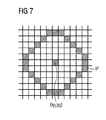
- Figure 7
- shows a diagram for illustrating a possible exemplary implementation of the method and apparatus according to the present invention;
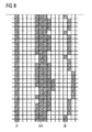
- Figure 8
- shows a further diagram for illustrating a possible exemplary implementation of a method and apparatus according to the present invention.
- As can be seen in
Figure 2 , the glare detection method according to the first aspect of the present invention can comprise several steps SA to SC as illustrated inFigure 2 . The glare detection method according to the present invention as shown inFigure 2 is provided for detection of at least one glare region within an image. The image can be a digital image captured by a camera of a system. In a possible embodiment, the image is a digital image captured by a vehicle camera of a driver assistance system. In a possible embodiment, the camera can be a fisheye camera of a surround view system of a vehicle. The image can be taken by the camera from the front, back, left or right side of the vehicle. - In a first step SA, image pixels of the captured image having a high luminance intensity are aggregated into bright image areas BIA within said image.
- In a further step SB, for image pixels around each bright image area BIA gradients expected in case of a glare and actual gradients are calculated.
- In a further step SC, a glare diameter of a glare region around the respective bright image area BIA is increased as long as the calculated actual gradients match the calculated expected gradients.
- In a possible embodiment, of the glare detection method similarity metrics between the calculated actual gradients and the calculated expected gradients are computed in step SC. Further, an average similarity value of the computed similarity values for image pixels being located in a neighboring image area NIA around the respective bright image area BIA and being equidistant to the respective bright image area BIA can be calculated. The average similarity value is calculated with a stepwise increasing distance between the equidistant image pixels IP of the neighboring image area NIA and the respective bright image area BIA until the respective calculated average similarity value becomes smaller than a predetermined threshold value. The equidistant image pixels IP of the last incrementing step define the outer boundary of the glare region within the captured image.
-
Figure 3 shows a flowchart of a possible exemplary embodiment of a glare detection method according to the first aspect of the present invention. - In a first step S1, an image is captured by a camera. The image may comprise for instance 1280x800 image pixels.
- In a further step S2, the image is downscaled and the downscaled image is then scanned for image pixels having a high luminance intensity above a predetermined luminance intensity threshold. This is done to reduce computational complexity and to reduce the effect of image noise. For example, the captured image can be reduced by a factor 15 in each direction, i.e. the downscaled image comprises a size being smaller by a factor of 15 when compared to the original captured image in each direction. If the original captured image comprises a size of 1280x800 image pixels the downscaled image comprises a size of 85x53 image pixels as illustrated in
Figure 3 . - The downscaled image is then scanned in step S3 for pixels that have a very high intensity value, for example 255 in an 8 bit luminance image starting at zero.
- These high intensity image pixels are then aggregated into bright image areas BIA within said image. In a possible embodiment, the image pixels of the downscaled image having a high luminance intensity above a predetermined luminance intensity threshold are aggregated into connected areas labelled as bright image areas of the image. For each labelled bright image area BIA, the central pixel can be found in step S4, for example through a simple average of the position of the pixels in the respective area.
- Since the gradient direction within glare regions is the same as an angle formed by the mean pixel of the area and the current image pixel as illustrated by the arrows in
Figure 1B , a set of expected gradient angles is computed in step S5 in the neighboring image area NIA of the bright image source. As can be seen inFigure 3 , in another branch of the illustrated flowchart the downscaled image is loaded and an actual gradient that is seen on the image is computed. Finally, given the gradient that is expected in case of a glare and the actual gradient in the captured image, a metric of similarity between the two values can be calculated for circles that are progressively further away from the bright light source in step S5. Accordingly, with the method according to the present invention in the illustrated embodiment, for image pixels IP around each bright image area BIA, gradients expected in case of a glare and actual gradients are calculated in calculating step S5. - Finally, a glare diameter of a glare region around the respective bright image area is increased as long as the calculated actual gradients match the calculated expected gradients in step S6. For a circular glare, for each radius, progressively further away from the center of the bright light source a number given by the average similarity metrics of the image pixels in the respective circle is computed. If the similarity metric becomes too low, it is deemed that the other boundary of the glare region has been reached. The average similarity value is calculated with a stepwise increased distance between the equidistant image pixels IP of the neighboring image area NIA and the respective bright image area BIA until the respective calculated average similarity value becomes smaller than a predetermined threshold value wherein the equidistant image pixels IP of the last incrementing step define the outer boundary of the glare region within the respective image.
- In more detail, if a pixel (x0, y0) is the computed center of a high luminance intensity area and (x, y) is a pixel in the neighborhood as illustrated in
Figure 5 , a gradient that is expected for a glare pixel in (x, y) is
- The actual gradient of the captured image can be calculated by:

- The computation of the similarity metric between the expected angle and the actual angle can comprise several substeps. In a first substep, the difference between the angles is computed.

- Then, the angle difference can be used to compute a similarity metric ε [-1, 1], where 1 means that the values are identical and -1 that the values are conflicting, as follows:

- A visual representation of the possible values of the similarity metric ε as a function of the difference between the angles is shown in
Figure 6 . - As illustrated in
Figure 6 , only gradients that are aligned with the respective gradient contribute positively to an assessment of whether the image pixels of a particular radius from the center of the bright image area constitute glare. - To assess if the image pixels IP at a particular radius r constitute glare, the following steps can be performed for a radius becoming progressively larger starting at 1. First, the image pixels IP at a particular radius from the center of the bright image area (x0, y0) are identified.
Figure 7 illustrates such image pixels for a radius r=5 around the center pixel (x0, y0). - To compute a similarity between the direction of the gradients of the image pixels IP at that radius r and the expected gradient all similarity metrics of such image pixels can be added and divided by the number of pixels, i.e. a mean similarity metric for that radius r is calculated. If the mean similarity metric is above a certain threshold TH it is considered that there is glare and the radius r is incremented and the next radius is checked. In a possible implementation, a similarity threshold of 0.5 can be used. If the mean similarity metric is below this threshold the limit or outer boundary of the glare region has been reached and the process stops. Because there is no information propagated along time, the detection of the glare according to the method of the present invention occurs instantaneously. In a possible embodiment, a glare is only detected if a glare region is detected around a bright image area BIA for a predetermined number N of images in an image sequence provided by a camera. In this embodiment, by requiring that glare detections are consistent along time, a glare is detected only if it is visible around the same area for N frames.
- With the glare detection method according to the present invention it is possible to detect circular shaped glare regions. In cases where the glare is not circular, an equivalent yet adapted process can be used. For example, if the glare exhibits a vertical streak the computation of the center (x0, y0) of the bright image area BIA and how equidistant points are found can be adapted. If 'Ω is a set of very bright points or pixels, for any pixel (x, y) one can find a pixel (x0, y0) E 'Ω that is closest to the respective pixel (x, y). Starting from here, the process can proceed as described above using equation (1) to compute the expected angles, equation (2) to compute the actual angles and then equations (3) and (4) to compute similarity metrics. At the end of the process instead of collecting the similarity metrics at a given radius from the center of the bright area, these similarity metrics are collected for pixels whose distance at any point in set 'Ω is given by a radius r.
-
Figure 8 illustrates such equidistant image points IP of the set 'Ω at a distance r=5. If the similarity metric for a given radius r is above a threshold the radius r is incremented and the next set of pixels is checked. This process continues until the similarity becomes smaller than a predetermined threshold value. -
Figure 4 shows a block diagram of a possible exemplary embodiment of aglare detection apparatus 1 according to a further aspect of the present invention. Theglare detection apparatus 1 according to the present invention comprises in the illustrated embodiment a downscalingunit 2 and aprocessing unit 3. The downscalingunit 2 is adapted to downscale an image received from at least one camera 4 as shown inFigure 4 . The camera 4 can be a camera of a surround view system of a vehicle. The camera 4 can be at the front, back, left or right side of the respective vehicle VEH. The downscalingunit 2 is adapted to downscale the received digital image. Theglare detection apparatus 1 further comprises aprocessing unit 3 configured to aggregate image pixels of the image having a high luminance intensity to bright image areas BIA within said image. Theprocessing unit 3 is further adapted to calculate for image pixels around each bright image area BIA gradients expected in case of a glare and actual gradients. Theprocessing unit 3 is further configured to increase a glare diameter of a glare region around the respective bright image area BIA as long as the calculated actual gradients match the calculated expected gradients. In a possible embodiment, theprocessing unit 3 is configured to compute similarity metrics between the calculated actual gradients and the calculated expected gradients and is configured to calculate an average similarity value of the computed similarity values for image pixels being located in a neighboring image area NIA around the respective bright image area BIA and being equidistant to the respective bright image area BIA. In a possible embodiment, theprocessing unit 3 of theapparatus 1 is configured to calculate an average similarity value with a stepwise increased distance between the equidistant image pixels IP of the neighboring image area NIA and the respective bright image BIA area until the respective calculated average similarity value becomes smaller than a predetermined threshold value. The equidistant image pixels - IP of the last incrementing step define then the outer boundary of the glare region within the received image.
- In a possible embodiment, the
processing unit 3 further processes the found glare region within the captured image. In a possible embodiment, the found glare region is filtered. In a further embodiment, another application program is informed about the detected glare region. In a still further possible embodiment, theprocessing unit 3 outputs a warning if a glare region in the captured image is detected. - The
glare detection apparatus 1 as shown inFigure 4 can form part of a driver assistance system of a vehicle VEH. The driver assistance system comprises at least one camera 4 configured to provide an image of the vehicle's VEH surrounding and theglare detection apparatus 1 as shown inFigure 4 . - The method and apparatus can also be employed in other systems, in particular surveillance systems, manufacturing systems and consumer electronic devices.
Claims (15)
- A glare detection method for detection of at least one glare region within an image,
said method comprising the steps of:a) aggregating (SA) image pixels of said image having a high luminance intensity into bright image areas within said image;(b) calculating (SB) for image pixels around each bright image area gradients expected in case of a glare and actual gradients; and(c) increasing (SC) a glare diameter of a glare region around the respective bright image area as long as the calculated actual gradients match the calculated expected gradients. - The glare detection method according to claim 1 wherein similarity metrics between the calculated actual gradients and the calculated expected gradients are computed.
- The glare detection method according to claim 2 wherein an average similarity value of the computed similarity values for image pixels being located in a neighboring image area around the respective bright image area and being equidistant to the respective bright image area is calculated.
- The glare detection method according to claim 3 wherein an average similarity value is calculated with a stepwise increased distance between the equidistant image pixels of the neighboring image area and the respective bright image area until the respective calculated average similarity value becomes smaller than a predetermined threshold value,
wherein the equidistant image pixels of the last incrementing step define the outer boundary of the glare region within said image. - The glare detection method according to one of the preceding claims 1 - 4 wherein the image forms part of an image sequence of images provided by a camera (4).
- The glare detection method according to claim 5 wherein a glare is detected if a glare region is detected around a bright image area for a predetermined number, N, of images in the image sequence provided by the camera (4).
- The glare detection method according to claim 5 or 6 wherein the image is generated by a camera (4) of a vehicle.
- The glare detection method according to one of the preceding claims 5 - 7 wherein the image provided by said camera (4) is a digital image comprising a plurality of pixels each having a luminance intensity.
- The glare detection method according to one of the previous claims 1 - 8 wherein the image is downscaled (S2) and the downscaled image is scanned for image pixels having a high luminance intensity above a predetermined luminance intensity threshold.
- The glare detection method according to claim 9 wherein the image pixels of the downscaled image having a high luminance intensity above the predetermined luminance intensity threshold are aggregated into connected areas labelled as bright image areas of said image.
- A glare detection apparatus (1) for detection of at least one glare region within an image,
said apparatus (1) comprising:a processing unit (3) configured to aggregate image pixels of said image having a high luminance intensity to bright image areas within said image and to calculate for image pixels around each bright image area gradients expected in case of a glare and actual gradients and configured to increase a glare diameter of a glare region around the respective bright image area as long as the calculated actual gradients match the calculated expected gradients. - The glare detection apparatus according to claim 11 said processing unit (3) being further configured to compute similarity metrics between the calculated actual gradients and the calculated expected gradients and being configured to calculate an average similarity value of the computed similarity values for image pixels being located in a neighboring image area around the respective bright image area and being equidistant to the respective bright image area.
- The glare detection apparatus according to claim 12 wherein said processing unit (3) is configured to calculate an average similarity value with a stepwise increased distance between the equidistant image pixels of the neighboring image area and the respective bright image area until the respective calculated average similarity value becomes smaller than a predetermined threshold value,
wherein the equidistant image pixels of the last incrementing step define the outer boundary of the glare region within said image. - The glare detection apparatus according to one of the preceding claims 11 - 13 wherein said apparatus (1) further comprises a downscaling unit (2) adapted to downscale the image,
wherein said downscaled image is scanned by the processing unit (3) for image pixels having a high luminance intensity above a predetermined luminance intensity threshold,
wherein image pixels of the downscaled image having a high luminance intensity above the predetermined luminance intensity are aggregated by the processing unit (3) into connected areas labelled as bright image areas of said image. - A driver assistance system of a vehicle comprising:at least one camera (4) configured to provide images of the vehicle's surrounding anda glare detection apparatus (1) according to one of the preceding claims 11 - 14.
Priority Applications (4)
| Application Number | Priority Date | Filing Date | Title |
|---|---|---|---|
| EP15183649.1A EP3138721B1 (en) | 2015-09-03 | 2015-09-03 | A method and apparatus for glare detection |
| PCT/EP2016/066468 WO2017036645A1 (en) | 2015-09-03 | 2016-07-12 | A method and apparatus for glare detection |
| JP2018511443A JP6701327B2 (en) | 2015-09-03 | 2016-07-12 | Glare detection method and device |
| US15/910,521 US10846557B2 (en) | 2015-09-03 | 2018-03-02 | Method and apparatus for glare detection |
Applications Claiming Priority (1)
| Application Number | Priority Date | Filing Date | Title |
|---|---|---|---|
| EP15183649.1A EP3138721B1 (en) | 2015-09-03 | 2015-09-03 | A method and apparatus for glare detection |
Publications (2)
| Publication Number | Publication Date |
|---|---|
| EP3138721A1 true EP3138721A1 (en) | 2017-03-08 |
| EP3138721B1 EP3138721B1 (en) | 2018-11-14 |
Family
ID=54065719
Family Applications (1)
| Application Number | Title | Priority Date | Filing Date |
|---|---|---|---|
| EP15183649.1A Active EP3138721B1 (en) | 2015-09-03 | 2015-09-03 | A method and apparatus for glare detection |
Country Status (4)
| Country | Link |
|---|---|
| US (1) | US10846557B2 (en) |
| EP (1) | EP3138721B1 (en) |
| JP (1) | JP6701327B2 (en) |
| WO (1) | WO2017036645A1 (en) |
Families Citing this family (7)
| Publication number | Priority date | Publication date | Assignee | Title |
|---|---|---|---|---|
| EP3389257A1 (en) | 2017-04-13 | 2018-10-17 | Continental Automotive GmbH | Method for adapting brightness of image data, image capturing system and advanced driver assistance system |
| US10609293B2 (en) * | 2018-08-20 | 2020-03-31 | Capital One Services, Llc | Real-time glare detection inside a dynamic region of an image |
| WO2020237366A1 (en) * | 2019-05-28 | 2020-12-03 | Punnappurath Abhijith | System and method for reflection removal using dual-pixel sensor |
| TWI877189B (en) * | 2019-09-27 | 2025-03-21 | 日商索尼半導體解決方案公司 | Information processing device, correction method and program |
| WO2022115809A1 (en) * | 2020-11-30 | 2022-06-02 | Lutron Technology Company Llc | Sensor for detecting glare conditions |
| US12498239B2 (en) * | 2022-06-16 | 2025-12-16 | At&T Intellectual Property I, L.P. | System for extended reality augmentation of situational navigation |
| WO2025147807A1 (en) * | 2024-01-08 | 2025-07-17 | 京东方科技集团股份有限公司 | Glare level measurement method, glare control method and apparatus therefor, and storage medium |
Citations (5)
| Publication number | Priority date | Publication date | Assignee | Title |
|---|---|---|---|---|
| US7206725B1 (en) * | 2001-12-06 | 2007-04-17 | Adobe Systems Incorporated | Vector-based representation of a lens flare |
| US20090147116A1 (en) * | 2007-12-07 | 2009-06-11 | Panasonic Corporation | Image-capturing apparatus, camera, vehicle, and image-capturing method |
| US20090161983A1 (en) * | 2007-12-21 | 2009-06-25 | Sony Corporation And Sony Electronics, Inc. | Method for automatic detection and correction of halo artifacts in images |
| EP2172873A2 (en) * | 2008-10-06 | 2010-04-07 | Mobileye Vision Technologies | Bundling of driver assistance systems |
| US20130329132A1 (en) * | 2012-06-06 | 2013-12-12 | Apple Inc. | Flare Detection and Mitigation in Panoramic Images |
Family Cites Families (12)
| Publication number | Priority date | Publication date | Assignee | Title |
|---|---|---|---|---|
| US8120652B2 (en) * | 1997-04-02 | 2012-02-21 | Gentex Corporation | System for controlling vehicle equipment |
| US7430303B2 (en) * | 2002-03-29 | 2008-09-30 | Lockheed Martin Corporation | Target detection method and system |
| US7683326B2 (en) * | 2002-07-09 | 2010-03-23 | Gentex Corporation | Vehicle vision system with high dynamic range |
| KR100594073B1 (en) * | 2002-09-17 | 2006-07-03 | 삼성전자주식회사 | Digital Image Scaling Method for Embedded System |
| JP3944151B2 (en) * | 2003-10-31 | 2007-07-11 | キヤノン株式会社 | Image processing method, image processing apparatus, and image processing program |
| JP5387007B2 (en) * | 2009-01-22 | 2014-01-15 | 日本電気株式会社 | Image processing apparatus, biometric authentication apparatus, image processing method, and program |
| US8109258B2 (en) * | 2009-07-31 | 2012-02-07 | Detroit Diesel Corporation | Method of diagnosing a slow EGR system in an internal combustion engine |
| KR101340765B1 (en) * | 2010-04-01 | 2013-12-11 | 신닛테츠스미킨 카부시키카이샤 | Particle measuring system and particle measuring method |
| EP2729915B1 (en) * | 2011-07-05 | 2017-12-27 | Omron Corporation | A method and apparatus for projective volume monitoring |
| DE102011081398B4 (en) * | 2011-08-23 | 2018-09-13 | Robert Bosch Gmbh | Method and apparatus for distinguishing a self-luminous object from a reflective object |
| EP2754125B1 (en) * | 2011-10-14 | 2017-01-18 | Omron Corporation | A method and apparatus for projective volume monitoring |
| JP2015142357A (en) * | 2014-01-30 | 2015-08-03 | 株式会社ニコン | image processing apparatus |
-
2015
- 2015-09-03 EP EP15183649.1A patent/EP3138721B1/en active Active
-
2016
- 2016-07-12 WO PCT/EP2016/066468 patent/WO2017036645A1/en not_active Ceased
- 2016-07-12 JP JP2018511443A patent/JP6701327B2/en active Active
-
2018
- 2018-03-02 US US15/910,521 patent/US10846557B2/en active Active
Patent Citations (5)
| Publication number | Priority date | Publication date | Assignee | Title |
|---|---|---|---|---|
| US7206725B1 (en) * | 2001-12-06 | 2007-04-17 | Adobe Systems Incorporated | Vector-based representation of a lens flare |
| US20090147116A1 (en) * | 2007-12-07 | 2009-06-11 | Panasonic Corporation | Image-capturing apparatus, camera, vehicle, and image-capturing method |
| US20090161983A1 (en) * | 2007-12-21 | 2009-06-25 | Sony Corporation And Sony Electronics, Inc. | Method for automatic detection and correction of halo artifacts in images |
| EP2172873A2 (en) * | 2008-10-06 | 2010-04-07 | Mobileye Vision Technologies | Bundling of driver assistance systems |
| US20130329132A1 (en) * | 2012-06-06 | 2013-12-12 | Apple Inc. | Flare Detection and Mitigation in Panoramic Images |
Also Published As
| Publication number | Publication date |
|---|---|
| WO2017036645A1 (en) | 2017-03-09 |
| EP3138721B1 (en) | 2018-11-14 |
| JP6701327B2 (en) | 2020-05-27 |
| US20180197039A1 (en) | 2018-07-12 |
| US10846557B2 (en) | 2020-11-24 |
| JP2018526922A (en) | 2018-09-13 |
Similar Documents
| Publication | Publication Date | Title |
|---|---|---|
| US10846557B2 (en) | Method and apparatus for glare detection | |
| CN104954664B (en) | Image processing apparatus and image processing method | |
| CN107533753B (en) | Image processing apparatus | |
| US9946941B2 (en) | Lane detection | |
| TWI607901B (en) | Image inpainting system area and method using the same | |
| JP6832105B2 (en) | Water drop detector, water drop detection method and water drop detection program | |
| CN104954663B (en) | Image processing apparatus and image processing method | |
| US20140055572A1 (en) | Image processing apparatus for a vehicle | |
| US10026158B2 (en) | Imaging device | |
| US20160026878A1 (en) | Algorithm to extend detecting range for avm stop line detection | |
| JP6375911B2 (en) | Curve mirror detector | |
| KR101402089B1 (en) | Apparatus and Method for Obstacle Detection | |
| US20140226908A1 (en) | Object detection apparatus, object detection method, storage medium, and integrated circuit | |
| KR101236223B1 (en) | Method for detecting traffic lane | |
| KR20130070210A (en) | Method for removing noise of image | |
| US9811744B2 (en) | Fast and robust stop line detector | |
| JP6313999B2 (en) | Object detection device and object detection system | |
| Ito et al. | An adherent raindrop detection method using MSER | |
| US20150104072A1 (en) | Lane detection method and system using photographing unit | |
| JP6258842B2 (en) | Image processing apparatus and lane boundary line recognition system | |
| KR101864765B1 (en) | Device and method using fish-eye lens distortion correction | |
| KR20140066847A (en) | Method and apparatus for recognizing speed limit signs | |
| EP3306522A1 (en) | Device for determining a region of interest on and/or within a vehicle windscreen | |
| TWI691940B (en) | Vehicle photography system and object detection method | |
| KR101705876B1 (en) | Method for detecting pedestrian candidate and method for recognizing pedestrian using the same |
Legal Events
| Date | Code | Title | Description |
|---|---|---|---|
| PUAI | Public reference made under article 153(3) epc to a published international application that has entered the european phase |
Free format text: ORIGINAL CODE: 0009012 |
|
| STAA | Information on the status of an ep patent application or granted ep patent |
Free format text: STATUS: THE APPLICATION HAS BEEN PUBLISHED |
|
| AK | Designated contracting states |
Kind code of ref document: A1 Designated state(s): AL AT BE BG CH CY CZ DE DK EE ES FI FR GB GR HR HU IE IS IT LI LT LU LV MC MK MT NL NO PL PT RO RS SE SI SK SM TR |
|
| AX | Request for extension of the european patent |
Extension state: BA ME |
|
| STAA | Information on the status of an ep patent application or granted ep patent |
Free format text: STATUS: REQUEST FOR EXAMINATION WAS MADE |
|
| 17P | Request for examination filed |
Effective date: 20170908 |
|
| RBV | Designated contracting states (corrected) |
Designated state(s): AL AT BE BG CH CY CZ DE DK EE ES FI FR GB GR HR HU IE IS IT LI LT LU LV MC MK MT NL NO PL PT RO RS SE SI SK SM TR |
|
| GRAP | Despatch of communication of intention to grant a patent |
Free format text: ORIGINAL CODE: EPIDOSNIGR1 |
|
| STAA | Information on the status of an ep patent application or granted ep patent |
Free format text: STATUS: GRANT OF PATENT IS INTENDED |
|
| INTG | Intention to grant announced |
Effective date: 20180424 |
|
| GRAS | Grant fee paid |
Free format text: ORIGINAL CODE: EPIDOSNIGR3 |
|
| GRAA | (expected) grant |
Free format text: ORIGINAL CODE: 0009210 |
|
| STAA | Information on the status of an ep patent application or granted ep patent |
Free format text: STATUS: THE PATENT HAS BEEN GRANTED |
|
| AK | Designated contracting states |
Kind code of ref document: B1 Designated state(s): AL AT BE BG CH CY CZ DE DK EE ES FI FR GB GR HR HU IE IS IT LI LT LU LV MC MK MT NL NO PL PT RO RS SE SI SK SM TR |
|
| REG | Reference to a national code |
Ref country code: CH Ref legal event code: EP Ref country code: AT Ref legal event code: REF Ref document number: 1064386 Country of ref document: AT Kind code of ref document: T Effective date: 20181115 |
|
| REG | Reference to a national code |
Ref country code: IE Ref legal event code: FG4D |
|
| REG | Reference to a national code |
Ref country code: DE Ref legal event code: R096 Ref document number: 602015019742 Country of ref document: DE |
|
| REG | Reference to a national code |
Ref country code: NL Ref legal event code: MP Effective date: 20181114 |
|
| REG | Reference to a national code |
Ref country code: LT Ref legal event code: MG4D |
|
| REG | Reference to a national code |
Ref country code: AT Ref legal event code: MK05 Ref document number: 1064386 Country of ref document: AT Kind code of ref document: T Effective date: 20181114 |
|
| PG25 | Lapsed in a contracting state [announced via postgrant information from national office to epo] |
Ref country code: ES Free format text: LAPSE BECAUSE OF FAILURE TO SUBMIT A TRANSLATION OF THE DESCRIPTION OR TO PAY THE FEE WITHIN THE PRESCRIBED TIME-LIMIT Effective date: 20181114 Ref country code: IS Free format text: LAPSE BECAUSE OF FAILURE TO SUBMIT A TRANSLATION OF THE DESCRIPTION OR TO PAY THE FEE WITHIN THE PRESCRIBED TIME-LIMIT Effective date: 20190314 Ref country code: BG Free format text: LAPSE BECAUSE OF FAILURE TO SUBMIT A TRANSLATION OF THE DESCRIPTION OR TO PAY THE FEE WITHIN THE PRESCRIBED TIME-LIMIT Effective date: 20190214 Ref country code: LT Free format text: LAPSE BECAUSE OF FAILURE TO SUBMIT A TRANSLATION OF THE DESCRIPTION OR TO PAY THE FEE WITHIN THE PRESCRIBED TIME-LIMIT Effective date: 20181114 Ref country code: HR Free format text: LAPSE BECAUSE OF FAILURE TO SUBMIT A TRANSLATION OF THE DESCRIPTION OR TO PAY THE FEE WITHIN THE PRESCRIBED TIME-LIMIT Effective date: 20181114 Ref country code: LV Free format text: LAPSE BECAUSE OF FAILURE TO SUBMIT A TRANSLATION OF THE DESCRIPTION OR TO PAY THE FEE WITHIN THE PRESCRIBED TIME-LIMIT Effective date: 20181114 Ref country code: NO Free format text: LAPSE BECAUSE OF FAILURE TO SUBMIT A TRANSLATION OF THE DESCRIPTION OR TO PAY THE FEE WITHIN THE PRESCRIBED TIME-LIMIT Effective date: 20190214 Ref country code: AT Free format text: LAPSE BECAUSE OF FAILURE TO SUBMIT A TRANSLATION OF THE DESCRIPTION OR TO PAY THE FEE WITHIN THE PRESCRIBED TIME-LIMIT Effective date: 20181114 Ref country code: FI Free format text: LAPSE BECAUSE OF FAILURE TO SUBMIT A TRANSLATION OF THE DESCRIPTION OR TO PAY THE FEE WITHIN THE PRESCRIBED TIME-LIMIT Effective date: 20181114 |
|
| PG25 | Lapsed in a contracting state [announced via postgrant information from national office to epo] |
Ref country code: AL Free format text: LAPSE BECAUSE OF FAILURE TO SUBMIT A TRANSLATION OF THE DESCRIPTION OR TO PAY THE FEE WITHIN THE PRESCRIBED TIME-LIMIT Effective date: 20181114 Ref country code: RS Free format text: LAPSE BECAUSE OF FAILURE TO SUBMIT A TRANSLATION OF THE DESCRIPTION OR TO PAY THE FEE WITHIN THE PRESCRIBED TIME-LIMIT Effective date: 20181114 Ref country code: SE Free format text: LAPSE BECAUSE OF FAILURE TO SUBMIT A TRANSLATION OF THE DESCRIPTION OR TO PAY THE FEE WITHIN THE PRESCRIBED TIME-LIMIT Effective date: 20181114 Ref country code: GR Free format text: LAPSE BECAUSE OF FAILURE TO SUBMIT A TRANSLATION OF THE DESCRIPTION OR TO PAY THE FEE WITHIN THE PRESCRIBED TIME-LIMIT Effective date: 20190215 Ref country code: NL Free format text: LAPSE BECAUSE OF FAILURE TO SUBMIT A TRANSLATION OF THE DESCRIPTION OR TO PAY THE FEE WITHIN THE PRESCRIBED TIME-LIMIT Effective date: 20181114 Ref country code: PT Free format text: LAPSE BECAUSE OF FAILURE TO SUBMIT A TRANSLATION OF THE DESCRIPTION OR TO PAY THE FEE WITHIN THE PRESCRIBED TIME-LIMIT Effective date: 20190314 |
|
| PG25 | Lapsed in a contracting state [announced via postgrant information from national office to epo] |
Ref country code: CZ Free format text: LAPSE BECAUSE OF FAILURE TO SUBMIT A TRANSLATION OF THE DESCRIPTION OR TO PAY THE FEE WITHIN THE PRESCRIBED TIME-LIMIT Effective date: 20181114 Ref country code: DK Free format text: LAPSE BECAUSE OF FAILURE TO SUBMIT A TRANSLATION OF THE DESCRIPTION OR TO PAY THE FEE WITHIN THE PRESCRIBED TIME-LIMIT Effective date: 20181114 Ref country code: PL Free format text: LAPSE BECAUSE OF FAILURE TO SUBMIT A TRANSLATION OF THE DESCRIPTION OR TO PAY THE FEE WITHIN THE PRESCRIBED TIME-LIMIT Effective date: 20181114 |
|
| REG | Reference to a national code |
Ref country code: DE Ref legal event code: R097 Ref document number: 602015019742 Country of ref document: DE |
|
| PG25 | Lapsed in a contracting state [announced via postgrant information from national office to epo] |
Ref country code: EE Free format text: LAPSE BECAUSE OF FAILURE TO SUBMIT A TRANSLATION OF THE DESCRIPTION OR TO PAY THE FEE WITHIN THE PRESCRIBED TIME-LIMIT Effective date: 20181114 Ref country code: SM Free format text: LAPSE BECAUSE OF FAILURE TO SUBMIT A TRANSLATION OF THE DESCRIPTION OR TO PAY THE FEE WITHIN THE PRESCRIBED TIME-LIMIT Effective date: 20181114 Ref country code: SK Free format text: LAPSE BECAUSE OF FAILURE TO SUBMIT A TRANSLATION OF THE DESCRIPTION OR TO PAY THE FEE WITHIN THE PRESCRIBED TIME-LIMIT Effective date: 20181114 Ref country code: RO Free format text: LAPSE BECAUSE OF FAILURE TO SUBMIT A TRANSLATION OF THE DESCRIPTION OR TO PAY THE FEE WITHIN THE PRESCRIBED TIME-LIMIT Effective date: 20181114 |
|
| PLBE | No opposition filed within time limit |
Free format text: ORIGINAL CODE: 0009261 |
|
| STAA | Information on the status of an ep patent application or granted ep patent |
Free format text: STATUS: NO OPPOSITION FILED WITHIN TIME LIMIT |
|
| 26N | No opposition filed |
Effective date: 20190815 |
|
| PG25 | Lapsed in a contracting state [announced via postgrant information from national office to epo] |
Ref country code: SI Free format text: LAPSE BECAUSE OF FAILURE TO SUBMIT A TRANSLATION OF THE DESCRIPTION OR TO PAY THE FEE WITHIN THE PRESCRIBED TIME-LIMIT Effective date: 20181114 |
|
| PG25 | Lapsed in a contracting state [announced via postgrant information from national office to epo] |
Ref country code: TR Free format text: LAPSE BECAUSE OF FAILURE TO SUBMIT A TRANSLATION OF THE DESCRIPTION OR TO PAY THE FEE WITHIN THE PRESCRIBED TIME-LIMIT Effective date: 20181114 |
|
| PG25 | Lapsed in a contracting state [announced via postgrant information from national office to epo] |
Ref country code: MC Free format text: LAPSE BECAUSE OF FAILURE TO SUBMIT A TRANSLATION OF THE DESCRIPTION OR TO PAY THE FEE WITHIN THE PRESCRIBED TIME-LIMIT Effective date: 20181114 |
|
| REG | Reference to a national code |
Ref country code: CH Ref legal event code: PL |
|
| PG25 | Lapsed in a contracting state [announced via postgrant information from national office to epo] |
Ref country code: LI Free format text: LAPSE BECAUSE OF NON-PAYMENT OF DUE FEES Effective date: 20190930 Ref country code: IE Free format text: LAPSE BECAUSE OF NON-PAYMENT OF DUE FEES Effective date: 20190903 Ref country code: LU Free format text: LAPSE BECAUSE OF NON-PAYMENT OF DUE FEES Effective date: 20190903 Ref country code: CH Free format text: LAPSE BECAUSE OF NON-PAYMENT OF DUE FEES Effective date: 20190930 |
|
| REG | Reference to a national code |
Ref country code: BE Ref legal event code: MM Effective date: 20190930 |
|
| PG25 | Lapsed in a contracting state [announced via postgrant information from national office to epo] |
Ref country code: BE Free format text: LAPSE BECAUSE OF NON-PAYMENT OF DUE FEES Effective date: 20190930 |
|
| PG25 | Lapsed in a contracting state [announced via postgrant information from national office to epo] |
Ref country code: CY Free format text: LAPSE BECAUSE OF FAILURE TO SUBMIT A TRANSLATION OF THE DESCRIPTION OR TO PAY THE FEE WITHIN THE PRESCRIBED TIME-LIMIT Effective date: 20181114 |
|
| PG25 | Lapsed in a contracting state [announced via postgrant information from national office to epo] |
Ref country code: HU Free format text: LAPSE BECAUSE OF FAILURE TO SUBMIT A TRANSLATION OF THE DESCRIPTION OR TO PAY THE FEE WITHIN THE PRESCRIBED TIME-LIMIT; INVALID AB INITIO Effective date: 20150903 Ref country code: MT Free format text: LAPSE BECAUSE OF FAILURE TO SUBMIT A TRANSLATION OF THE DESCRIPTION OR TO PAY THE FEE WITHIN THE PRESCRIBED TIME-LIMIT Effective date: 20181114 |
|
| PG25 | Lapsed in a contracting state [announced via postgrant information from national office to epo] |
Ref country code: MK Free format text: LAPSE BECAUSE OF FAILURE TO SUBMIT A TRANSLATION OF THE DESCRIPTION OR TO PAY THE FEE WITHIN THE PRESCRIBED TIME-LIMIT Effective date: 20181114 |
|
| REG | Reference to a national code |
Ref country code: DE Ref legal event code: R081 Ref document number: 602015019742 Country of ref document: DE Owner name: CONTINENTAL AUTONOMOUS MOBILITY GERMANY GMBH, DE Free format text: FORMER OWNER: CONTINENTAL AUTOMOTIVE GMBH, 30165 HANNOVER, DE Ref country code: DE Ref legal event code: R081 Ref document number: 602015019742 Country of ref document: DE Owner name: AUMOVIO AUTONOMOUS MOBILITY GERMANY GMBH, DE Free format text: FORMER OWNER: CONTINENTAL AUTOMOTIVE GMBH, 30165 HANNOVER, DE |
|
| REG | Reference to a national code |
Ref country code: GB Ref legal event code: 732E Free format text: REGISTERED BETWEEN 20230126 AND 20230201 |
|
| REG | Reference to a national code |
Ref country code: DE Ref legal event code: R081 Ref document number: 602015019742 Country of ref document: DE Owner name: AUMOVIO AUTONOMOUS MOBILITY GERMANY GMBH, DE Free format text: FORMER OWNER: CONTINENTAL AUTONOMOUS MOBILITY GERMANY GMBH, 85057 INGOLSTADT, DE |
|
| PGFP | Annual fee paid to national office [announced via postgrant information from national office to epo] |
Ref country code: DE Payment date: 20250930 Year of fee payment: 11 |
|
| PGFP | Annual fee paid to national office [announced via postgrant information from national office to epo] |
Ref country code: IT Payment date: 20250923 Year of fee payment: 11 |
|
| PGFP | Annual fee paid to national office [announced via postgrant information from national office to epo] |
Ref country code: GB Payment date: 20250919 Year of fee payment: 11 |
|
| PGFP | Annual fee paid to national office [announced via postgrant information from national office to epo] |
Ref country code: FR Payment date: 20250922 Year of fee payment: 11 |