EP3138681A1 - Blow-molded container with in-mold label and method for manufacturing blow-molded container with in-mold label - Google Patents
Blow-molded container with in-mold label and method for manufacturing blow-molded container with in-mold label Download PDFInfo
- Publication number
- EP3138681A1 EP3138681A1 EP15786172.5A EP15786172A EP3138681A1 EP 3138681 A1 EP3138681 A1 EP 3138681A1 EP 15786172 A EP15786172 A EP 15786172A EP 3138681 A1 EP3138681 A1 EP 3138681A1
- Authority
- EP
- European Patent Office
- Prior art keywords
- mold
- glued
- container
- blow
- portions
- Prior art date
- Legal status (The legal status is an assumption and is not a legal conclusion. Google has not performed a legal analysis and makes no representation as to the accuracy of the status listed.)
- Granted
Links
Images


Classifications
-
- B—PERFORMING OPERATIONS; TRANSPORTING
- B65—CONVEYING; PACKING; STORING; HANDLING THIN OR FILAMENTARY MATERIAL
- B65D—CONTAINERS FOR STORAGE OR TRANSPORT OF ARTICLES OR MATERIALS, e.g. BAGS, BARRELS, BOTTLES, BOXES, CANS, CARTONS, CRATES, DRUMS, JARS, TANKS, HOPPERS, FORWARDING CONTAINERS; ACCESSORIES, CLOSURES, OR FITTINGS THEREFOR; PACKAGING ELEMENTS; PACKAGES
- B65D23/00—Details of bottles or jars not otherwise provided for
- B65D23/08—Coverings or external coatings
-
- B—PERFORMING OPERATIONS; TRANSPORTING
- B29—WORKING OF PLASTICS; WORKING OF SUBSTANCES IN A PLASTIC STATE IN GENERAL
- B29C—SHAPING OR JOINING OF PLASTICS; SHAPING OF MATERIAL IN A PLASTIC STATE, NOT OTHERWISE PROVIDED FOR; AFTER-TREATMENT OF THE SHAPED PRODUCTS, e.g. REPAIRING
- B29C49/00—Blow-moulding, i.e. blowing a preform or parison to a desired shape within a mould; Apparatus therefor
- B29C49/24—Lining or labelling
-
- B—PERFORMING OPERATIONS; TRANSPORTING
- B29—WORKING OF PLASTICS; WORKING OF SUBSTANCES IN A PLASTIC STATE IN GENERAL
- B29C—SHAPING OR JOINING OF PLASTICS; SHAPING OF MATERIAL IN A PLASTIC STATE, NOT OTHERWISE PROVIDED FOR; AFTER-TREATMENT OF THE SHAPED PRODUCTS, e.g. REPAIRING
- B29C49/00—Blow-moulding, i.e. blowing a preform or parison to a desired shape within a mould; Apparatus therefor
- B29C49/24—Lining or labelling
- B29C49/2408—In-mould lining or labelling
-
- B—PERFORMING OPERATIONS; TRANSPORTING
- B65—CONVEYING; PACKING; STORING; HANDLING THIN OR FILAMENTARY MATERIAL
- B65D—CONTAINERS FOR STORAGE OR TRANSPORT OF ARTICLES OR MATERIALS, e.g. BAGS, BARRELS, BOTTLES, BOXES, CANS, CARTONS, CRATES, DRUMS, JARS, TANKS, HOPPERS, FORWARDING CONTAINERS; ACCESSORIES, CLOSURES, OR FITTINGS THEREFOR; PACKAGING ELEMENTS; PACKAGES
- B65D1/00—Rigid or semi-rigid containers having bodies formed in one piece, e.g. by casting metallic material, by moulding plastics, by blowing vitreous material, by throwing ceramic material, by moulding pulped fibrous material or by deep-drawing operations performed on sheet material
- B65D1/02—Bottles or similar containers with necks or like restricted apertures, designed for pouring contents
-
- B—PERFORMING OPERATIONS; TRANSPORTING
- B65—CONVEYING; PACKING; STORING; HANDLING THIN OR FILAMENTARY MATERIAL
- B65D—CONTAINERS FOR STORAGE OR TRANSPORT OF ARTICLES OR MATERIALS, e.g. BAGS, BARRELS, BOTTLES, BOXES, CANS, CARTONS, CRATES, DRUMS, JARS, TANKS, HOPPERS, FORWARDING CONTAINERS; ACCESSORIES, CLOSURES, OR FITTINGS THEREFOR; PACKAGING ELEMENTS; PACKAGES
- B65D1/00—Rigid or semi-rigid containers having bodies formed in one piece, e.g. by casting metallic material, by moulding plastics, by blowing vitreous material, by throwing ceramic material, by moulding pulped fibrous material or by deep-drawing operations performed on sheet material
- B65D1/02—Bottles or similar containers with necks or like restricted apertures, designed for pouring contents
- B65D1/0223—Bottles or similar containers with necks or like restricted apertures, designed for pouring contents characterised by shape
- B65D1/023—Neck construction
- B65D1/0246—Closure retaining means, e.g. beads, screw-threads
-
- B—PERFORMING OPERATIONS; TRANSPORTING
- B65—CONVEYING; PACKING; STORING; HANDLING THIN OR FILAMENTARY MATERIAL
- B65D—CONTAINERS FOR STORAGE OR TRANSPORT OF ARTICLES OR MATERIALS, e.g. BAGS, BARRELS, BOTTLES, BOXES, CANS, CARTONS, CRATES, DRUMS, JARS, TANKS, HOPPERS, FORWARDING CONTAINERS; ACCESSORIES, CLOSURES, OR FITTINGS THEREFOR; PACKAGING ELEMENTS; PACKAGES
- B65D23/00—Details of bottles or jars not otherwise provided for
-
- B—PERFORMING OPERATIONS; TRANSPORTING
- B29—WORKING OF PLASTICS; WORKING OF SUBSTANCES IN A PLASTIC STATE IN GENERAL
- B29C—SHAPING OR JOINING OF PLASTICS; SHAPING OF MATERIAL IN A PLASTIC STATE, NOT OTHERWISE PROVIDED FOR; AFTER-TREATMENT OF THE SHAPED PRODUCTS, e.g. REPAIRING
- B29C49/00—Blow-moulding, i.e. blowing a preform or parison to a desired shape within a mould; Apparatus therefor
- B29C49/24—Lining or labelling
- B29C2049/2412—Lining or labelling outside the article
-
- B—PERFORMING OPERATIONS; TRANSPORTING
- B29—WORKING OF PLASTICS; WORKING OF SUBSTANCES IN A PLASTIC STATE IN GENERAL
- B29C—SHAPING OR JOINING OF PLASTICS; SHAPING OF MATERIAL IN A PLASTIC STATE, NOT OTHERWISE PROVIDED FOR; AFTER-TREATMENT OF THE SHAPED PRODUCTS, e.g. REPAIRING
- B29C49/00—Blow-moulding, i.e. blowing a preform or parison to a desired shape within a mould; Apparatus therefor
- B29C49/24—Lining or labelling
- B29C2049/2431—Means for preparing or treating the label or lining, e.g. cutting, deforming, heating or applying adhesive
- B29C2049/2433—Heating or applying adhesive
-
- B—PERFORMING OPERATIONS; TRANSPORTING
- B29—WORKING OF PLASTICS; WORKING OF SUBSTANCES IN A PLASTIC STATE IN GENERAL
- B29K—INDEXING SCHEME ASSOCIATED WITH SUBCLASSES B29B, B29C OR B29D, RELATING TO MOULDING MATERIALS OR TO MATERIALS FOR MOULDS, REINFORCEMENTS, FILLERS OR PREFORMED PARTS, e.g. INSERTS
- B29K2023/00—Use of polyalkenes or derivatives thereof as moulding material
- B29K2023/04—Polymers of ethylene
- B29K2023/06—PE, i.e. polyethylene
- B29K2023/0608—PE, i.e. polyethylene characterised by its density
- B29K2023/065—HDPE, i.e. high density polyethylene
-
- B—PERFORMING OPERATIONS; TRANSPORTING
- B29—WORKING OF PLASTICS; WORKING OF SUBSTANCES IN A PLASTIC STATE IN GENERAL
- B29K—INDEXING SCHEME ASSOCIATED WITH SUBCLASSES B29B, B29C OR B29D, RELATING TO MOULDING MATERIALS OR TO MATERIALS FOR MOULDS, REINFORCEMENTS, FILLERS OR PREFORMED PARTS, e.g. INSERTS
- B29K2023/00—Use of polyalkenes or derivatives thereof as moulding material
- B29K2023/10—Polymers of propylene
- B29K2023/12—PP, i.e. polypropylene
-
- B—PERFORMING OPERATIONS; TRANSPORTING
- B29—WORKING OF PLASTICS; WORKING OF SUBSTANCES IN A PLASTIC STATE IN GENERAL
- B29K—INDEXING SCHEME ASSOCIATED WITH SUBCLASSES B29B, B29C OR B29D, RELATING TO MOULDING MATERIALS OR TO MATERIALS FOR MOULDS, REINFORCEMENTS, FILLERS OR PREFORMED PARTS, e.g. INSERTS
- B29K2105/00—Condition, form or state of moulded material or of the material to be shaped
- B29K2105/25—Solid
- B29K2105/253—Preform
- B29K2105/258—Tubular
-
- B—PERFORMING OPERATIONS; TRANSPORTING
- B29—WORKING OF PLASTICS; WORKING OF SUBSTANCES IN A PLASTIC STATE IN GENERAL
- B29K—INDEXING SCHEME ASSOCIATED WITH SUBCLASSES B29B, B29C OR B29D, RELATING TO MOULDING MATERIALS OR TO MATERIALS FOR MOULDS, REINFORCEMENTS, FILLERS OR PREFORMED PARTS, e.g. INSERTS
- B29K2995/00—Properties of moulding materials, reinforcements, fillers, preformed parts or moulds
- B29K2995/0018—Properties of moulding materials, reinforcements, fillers, preformed parts or moulds having particular optical properties, e.g. fluorescent or phosphorescent
- B29K2995/0026—Transparent
-
- B—PERFORMING OPERATIONS; TRANSPORTING
- B29—WORKING OF PLASTICS; WORKING OF SUBSTANCES IN A PLASTIC STATE IN GENERAL
- B29L—INDEXING SCHEME ASSOCIATED WITH SUBCLASS B29C, RELATING TO PARTICULAR ARTICLES
- B29L2031/00—Other particular articles
- B29L2031/712—Containers; Packaging elements or accessories, Packages
Definitions
- the present invention relates to a blow-molded container with an in-mold label and a method for manufacturing a blow-molded container with an in-mold label.
- a blow-molded container with an in-mold label in which in-mold labels are glued on an outer peripheral surface of the container body is known.
- This container is formed by arranging the in-mold labels within a cavity of molds together with a preliminary molded body and blow-molding the preliminary molded body, thereby forming a container body and gluing the in-mold labels on an outer peripheral surface of a body portion.
- Patent Document 1 Japanese Unexamined Patent Application, First Publication No. 2004-136486
- the in-mold labels are glued only on the planar portions of the body portions.
- the display area of the in-mold labels may be narrow, and the size, the amount of information, and the like of characters, illustrations, and the like may be limited.
- the invention has been made in consideration of such circumstances, and an object thereof is to provide a blow-molded container with an in-mold label and a method for manufacturing a blow-molded container with an in-mold label in which air collection can be made difficult to occur between corner surfaces and the in-mold labels.
- a blow-molded container with an in-mold label of the invention includes a container body having a body portion that forms a square shape in which planar portions and corner surfaces are alternately and continuously provided around a container axis, in a cross-sectional view orthogonal to the container axis; and in-mold labels, which are integrally glued on outer peripheral surfaces of glued portions, ranging from the corner surfaces to the respective planar portions continuing on both sides of the corner surfaces around the container axis, in the body portion.
- a method for manufacturing a blow-molded container with an in-mold label of the invention is a method for manufacturing a blow-molded container with an in-mold label including a container body having a body portion that forms a square shape in which planar portions and corner surfaces are alternately and continuously provided around a container axis, in a cross-sectional view orthogonal to the container axis; and in-mold labels, which are integrally glued on outer peripheral surfaces of glued portions, ranging from the corner surfaces to the respective planar portions continuing on both sides of the corner surfaces around the container axis, in the body portion.
- the method includes a setting process of arranging a preliminary molded body and the in-mold labels within a cavity; and a blow-molding process of blow-molding the preliminary molded body to form the container body and gluing the in-mold labels on the outer peripheral surfaces of the glued portions.
- multiple recesses are formed over the entire back surfaces, which are glued to the outer peripheral surfaces of the glued portions, when the tensile elasticity of the in-mold labels is E (MPa) and the thickness of the in-mold labels is t (mm), E x t 3 satisfies 0.20 or less, and, when the radius of curvature of the corner surfaces is R (mm) and the angle formed between the planar portions is ⁇ (°) in a cross-sectional view of the glued portions, R x ⁇ 2 is 45000 or more.
- the multiple recesses are formed on the back surfaces of the in-mold labels.
- the in-mold labels bend, the volume of the recesses located in these portions decreases. Therefore, the in-mold labels not only can be made easily made to conform to the external shape of the above glued portions of the body portion, but also can be inhibited from thermally contracting when heated due to the temperature of the preliminary molded body when the container body is molded.
- the in-mold labels when the in-mold labels are glued on the outer peripheral surfaces of the above glued portions, the in-mold labels can be naturally deformed along the above glued portions, and the in-mold labels can be glued on the above glued portions without causing air to collect between the in-mold labels and the corner surfaces.
- R x ⁇ 2 is 45000 or more.
- the curvature radius R of the corner surfaces becomes greater as the angle ⁇ formed between the planar portions adjacent to each other around the container axis becomes a smaller acute angle.
- the multiple recesses are formed in the back surfaces of the in-mold labels.
- blow molding not only can the air between the container body or the preliminary molded body and the in-mold labels easily escape to the outside through the recesses, but also it is possible to house the air, which could not have escaped, within the recesses, and occurrence of air collection can be more reliably suppressed.
- the depth of the recesses may be 0.01 mm or more, and the proportion of the total plane area occupied by the multiple recesses of the in-mold labels may be 10% or more.
- the proportion of the total plane area occupied by the multiple recesses of the in-mold labels may be 10% or more, and the depth of the recesses may be 0.02 mm or more in a state before the in-mold labels are glued on an outer peripheral surface of the body portion.
- corresponding portions glued on outer peripheral surfaces of the corner surface in the in-mold labels may be stuck on an inner surface of the cavity in the blow molding process.
- a blow-molded container with an in-mold label in which air collection does not easily occur between the corner surfaces and the in-mold labels can be manufactured.
- blow-molded container 1 with an in-mold label related to an embodiment of the invention will be described with reference to the drawings.
- a blow-molded container 1 with an in-mold label of the present embodiment includes a container body 15 in which a bottom portion 11, a body portion 12, a shoulder portion 13, and a mouth portion 14 are continuously provided in this order, and an in-mold label 16 glued on the body portion 12.
- Respective central axes of the bottom portion 11, the body portion 12, the shoulder portion 13, and the mouth portion 14 in the container body 15 are arranged coaxially with a common axis.
- this common axis is referred to as a container axis O
- a bottom portion 11 side in the direction of the container axis O is referred to as a lower side
- a side opposite to this lower side is referred to as an upper side.
- a direction orthogonal to the container axis O is referred to as a radial direction
- a direction going around the container axis O is referred to as a circumferential direction.
- the container body 15 is integrally formed of, for example, synthetic resin materials, such as high-density polyethylene resin or polypropylene resin.
- the container body 15 has an internal capacity of, for example, about 370 ml.
- a peripheral wall portion of the bottom portion 11 is formed in the shape of a curved surface that protrudes toward a radial outer side, and gradually extends upward from a grounding portion 11a toward the radial outer side.
- the shoulder portion 13 couples an upper end of the body portion 12 and a lower end of the mouth portion 14 together, is formed in the shape of a curved surface that protrudes toward the radial outer side, and gradually extends toward a radial inner side upward from below.
- the body portion 12 extends straight over the entire length in the direction of the container axis O. Additionally the body portion 12 forms a square shape in which planar portions 20 and corner surfaces 21, 22, 23, and 24 are alternately and continuously provided around the container axis O, in a cross-sectional view orthogonal to the container axis O.
- the body portion 12 forms a rectangular shape in the above cross-sectional view.
- the body portion 12 forms a rectangular shape of which one side is about 75 mm in the above cross-sectional view.
- the planar portions 20 are slightly curved so as to protrude toward the radial outer side.
- the planar portions 20 may extend straight in the above cross-sectional view.
- the corner surfaces 21 to 24 are formed in the shape of a curved surface that protrudes toward the radial outer side. In the above cross-sectional view, the curvature radius R of the corner surfaces 21 to 24 is smaller than the curvature radius of the planar portions 20.
- R x ⁇ 2 is 45000 or more.
- the curvature radius R is about 4 mm to 40 mm, and the angle ⁇ is about 45° to 135°.
- the curvature radius of one corner surface (hereinafter referred to as a maximum corner surface) 21 of the four corner surfaces 21 to 24 R is greater than that of the other three corner surfaces 22 to 24, and the curvature radius R of the maximum corner surface 21 is, for example, about 22 mm, the curvature radius R of the other three corner surfaces 22 to 24 is, for example, about 12.5mm, and the angle ⁇ is, for example, 90° between the planar portions 20 adjacent to each other around the container axis O. That is, R x ⁇ 2 is 178200 in the maximum corner surface 21, and is 101250 in the other three corner surfaces 22 to 24.
- the distance from the container axis O in the radial direction is the shortest in the maximum corner surface 21 among the four corner surfaces 21 to 24.
- in-mold labels 16 are respectively glued on portions ranging from the maximum corner surface 21 to respective planar portions 20 continuing on both sides of the maximum corner surface 21 around the container axis O, and portions ranging from the corner surface (hereinafter referred to as an opposite corner surface) 22 that faces the maximum corner surface 21 in the radial direction to respective planar portions 20 continuing on both sides of the opposite corner surface 22 around the container axis O, in an outer peripheral surface of the body portion 12.
- respective portions on which the in-mold labels 16 are glued, in the outer peripheral surface of the body portion 12 are referred to as glued portions.
- the respective in-mold labels 16 are spaced apart from each other in the circumferential direction, and are glued at positions where a portioning line is avoided, in the outer peripheral surfaces of the body portion 12.
- Multiple recesses 25 are formed on a back surface bonded on the outer peripheral surface of the body portion 12 out of front and back surfaces of each in-mold label 16 over its whole region.
- the multiple recesses 25 are formed with the same shape as each other in a plan view and with the same size as each other, and are arranged at equal intervals on the back surface of the in-mold label 16.
- the recesses 25 are formed in a square shape in the plan view, and are arranged on the back surface of the in-mold label 16 in a state where the recesses are aligned so that the portion of the back surface where the recesses 25 are not formed forms a lattice shape in the plan view.
- the aspect of the shape or arrangement of the recesses 25 may be appropriately changed without being limited to the present embodiment.
- the depth of the recesses 25 is 0.01 mm or more and preferably 0.08 mm or less.
- the depth of the recesses 25 is 0.02 mm or more and preferably 0.10 mm or less, and the total of the internal volumes of all of a plurality of recesses 25 that are located in a unit region where a plane area is 1 cm 2 , in the in-mold label 16, is, for example, about 0.001 cm 3 to 0.005 cm 3 .
- E x t 3 satisfies 0.20 or less, and preferably, 0.05 or more
- the number of the recesses 25 that are located in a unit region where a plane area is 1 cm 2 , in an in-mold label 16 is for example, about 25 pieces to 2500 pieces
- the proportion of the total plane area occupied by the multiple recesses 25 of the in-mold label 16 is 10% or more and preferably 70% or less.
- the thickness t of the in-mold label 16 is, for example, about 0.04 mm to 0.10 mm.
- the tensile elasticity E is, for example, about 110 MPa to 250 MPa.
- E x t 3 is less than 0.05, the rigidity of an in-mold label becomes two weak, the handling thereof becomes difficult, and the in-mold label is not easily set in molds 31 and 32 to be described below. If the proportion of the total plane area of multiple recesses that occupies the plane area of an in-mold label exceeds 70%, the gluing area of the in-mold label with respect to the above glued portions may decrease and glue strength decrease, or when in-mold labels are automatically supplied into the cavity C using a device, multiple sheets of bundled in-mold labels may not be able to be suctioned and taken out sheet by sheet.
- the thickness t of the in-mold label 16 was obtained by measuring portions of the label 16 where the recesses 25 are not formed. Additionally, the tensile elasticity E was measured by pulling a test piece, which is obtained by forming the in-mold label 16 in a shape based on ASTM D-1822-L, at a speed of 1 mm/1 minute.
- the numerical value of E x t 3 , the number of the recesses 25 included in the above unit region, and the proportion of the total plane area of the multiple recesses 25 that occupies the plane area of the in-mold label 16 do not vary substantially before and after the in-mold label 16 is glued on the body portion 12.
- through-holes are discontinuously over the entire length in the direction of the container axis O in corresponding portions 16a glued on respective outer peripheral surfaces of the maximum corner surface 21 and the opposite corner surface 22 of the body portion 12 in each in-mold label 16.
- the in-mold label 16 includes the following four types of, for example, type A, type B, type C, and type D.
- a transparent base material layer 41 consisting of a non-extended cast film made of polypropylene resin, a printing layer 42, an anchor coat layer 43, and a glue layer 44 made of low-density polyethylene resin are laminated in this order from a front surface side toward a back surface side.
- the in-mold label 16 is formed so as to be sequentially laminated from the front surface side toward the back surface side.
- the printing layer 42 is formed by, for example, gravure printing, screen printing, or flexographic printing being performed on a back surface side of the base material layer 41.
- the anchor coat layer 43 is formed of, for example, materials obtained by diluting polyethyleneimine, polyetherpolyol polysiocyanate, or polyesterpolyol polysiocyanate with water or an organic solvent.
- the glue layer 44 is formed by, for example, an extrusion laminating method being performed on a back surface side of the anchor coat layer 43. Additionally, the recesses 25 are formed by performing embossing in a back surface of the glue layer 44 after the glue layer 44 is cooled and solidified with a cooling roller.
- the recesses are formed not only in the glue layer 44 but also in the respective back surfaces of the base material layer 41, the printing layer 42, and the anchor coat layer 43, and protrusions are formed in the respective front surfaces of the base material layer 41, the printing layer 42, the anchor coat layer 43, and the glue layer 44 in correspondence with the recesses.
- the thickness of the base material layer 41 is about 0.070 mm, and the thickness of the glue layer 44 is about 0.010 mm.
- a protective layer 45 made of low-density polypropylene resin, the anchor coat layer 43, the printing layer 42, and a glue layer 46 consisting of a non-extended cast film made of polyethylene resin are laminated in this order from a front surface side toward a back surface side.
- the in-mold label 16 is formed so as to be sequentially laminated from the back surface side toward the front surface side.
- the protective layer 45 is formed by, for example, an extrusion laminating method being performed on front surface side of the anchor coat layer 43.
- the recesses 25 are formed by performing embossing in a back surface of the glue layer 46 after the protective layer 45 is cooled and solidified with a cooling roller.
- the recesses are formed not only in the glue layer 46 but also in the respective back surfaces of the protective layer 45, the anchor coat layer 43, and the printing layer 42, and protrusions are formed in the respective front surfaces of the protective layer 45, the anchor coat layer 43, the printing layer 42, and the glue layer 46 which are in correspondence with the recesses.
- the thickness of the protective layer 45 is about 0.010 mm, and the thickness of the glue layer 46 is about 0.070 mm.
- the base material layer 41, the printing layer 42, a first anchor coat layer 43a, an extrusion resin layer 47 made of low-density polyethylene resin, a second anchor coat layer 43b, the glue layer 46 consisting of a non-extended cast film made of polypropylene resin are laminated in this order from a front surface side toward a back surface side.
- the recesses 25 formed in the back surface of the glue layer 46 reach a front surface of the glue layer 46, front and back surfaces of the second anchor coat layer 43b, and even a back surface of the extrusion resin layer 47, and a front surface of the extrusion resin layer 47, the first anchor coat layer 43a, the printing layer 42, and the base material layer 41 are flat.
- the in-mold label 16 is formed by the flat extrusion resin layer 47 in a softened state being sandwiched between a first film 48 including the base material layer 41, the printing layer 42, and the first anchor coat layer 43a and a second film 49 including the glue layer 46 where the recesses 25 are formed and the second anchor coat layer 43b and by projection portions 49a corresponding to the recesses 25 on the front surface side of the second film 49 being recessed into the extrusion resin layer 47.
- first and second anchor coat layers 43a and 43b are formed of the same materials as the anchor coat layer 43 in type A and type B.
- the thickness of the base material layer 41 is about 0.030 mm, and the thickness of the glue layer 46 is about 0.050 mm.
- the transparent base material layer 41, the printing layer 42, the anchor coat layer 43, and the glue layer 44 made of low-density polyethylene resin are laminated in this order from a front surface side toward a back surface side.
- the depth of the recesses 25 falls within a thickness range of the glue layer 44, and the base material layer 41, the printing layer 42, and the anchor coat layer 43 are flat.
- the in-mold label 16 is formed so as to be sequentially laminated from the front surface side toward the back surface side.
- the recesses 25 are formed simultaneously when an embossing roll is made to abut against and cool the back surface of the glue layer 44 after the glue layer 44 is formed with a thickness of, or example, about 0.005 mm to 0.030 mm by forming, for example, an extrusion laminating method on a back surface of the anchor coat layer 43.
- the thickness of the base material layer 41 is about 0.040 mm, and the thickness of the glue layer 44 is about 0.020 mm.
- the thickness of the base material layer 41 is, for example, about 0.03 mm to 0.08 mm.
- the molding mold 30 includes an extruder (not shown) that extrusion-molds a cylindrical parison (preliminary molded body) W, and a pair of molds 31 and 32 that is provided so as to be capable of being brought closer to or separated from each other and has a cavity C, having the same inner surface shape as the outer surface shape of the container body 15 to be molded, formed between mold surfaces 31a and 32a in a mold clamping state.
- the pair of molds 31 and 32 is disposed so that a portioning line is located in a diagonal portion where two corner surfaces 23 and 24 on which the in-mold labels 16 are not glued are located, among two sets of diagonal portions in the body portion 12 of the container body 15.
- First and second intake passages 33 and 34 that open to an inner surface of the cavity C are formed in the molds 31 and 32.
- the first and second intake passages 33 and 34 respectively open to a portion C1 that forms the maximum corner surface 21 of the body portion 12 of the container body 15, portions C2 that form the pair of planar portions 20 continuing on the maximum corner surface 21 in the circumferential direction, a portion C3 that forms the opposite corner surface 22, and portions C4 that form the pair of planar portions 20 continuing on the opposite corner surface 22 in the circumferential direction, in the inner surface of the cavity C.
- the first intake passages 33 which open to the portion C1 that forms the maximum corner surface 21 and the portion C3 that forms the opposite corner surface 22, in the inner surface of the cavity C, among the first and second intake passages 33 and 34, extend in the direction of the container axis O, and allow the in-mold labels 16 over the substantially entire length thereof in the direction of the container axis O to be suctioned therethrough.
- the length, in the direction of the container axis O, of the in-mold labels 16 suctioned by the first intake passages 33 may not be the entire length of the in-mold labels 16 in the direction of the container axis O as long as the length is such that the position of the corresponding portions 16a of the in-mold labels 16 with respect to the inner surface of the cavity C can be fixed in blow molding to be described below.
- an in-mold label 16 is integrally arranged from the portion C1 that forms the maximum corner surface 21 to the portions C2 that form the pair of planar portions 20 continuing on the maximum corner surface 21 in the circumferential direction, in the inner surface of the cavity C of the molds 31 and 32. Additionally, an in-mold label 16 that is separate from the above in-mold label is integrally arranged from the portion C3 that forms the opposite corner surface 22 to the portions C4 that form the pair of planar portions 20 continuing on the opposite corner surface 22 in the circumferential direction, in the inner surface of the cavity C of the molds 31 and 32.
- the in-mold labels 16 are stuck on the inner surface of the cavity C by applying a negative pressure to the respective in-mold labels 16 through the first and second intake passages 33 and 34.
- the corresponding portion 16a which is located in the portion C1 that forms the maximum corner surface 21 in the inner surface of the cavity C
- the corresponding portion 16a, which is located in the portion C3 that forms the opposite corner surface 22 in the inner surface of the cavity C, in the respective in-mold labels 16 are suctioned toward the inner surface of the cavity C over the substantially entire length thereof in the direction of the container axis O.
- the cylindrical parison W extrusion-molded from the extruder (not shown) is sandwiched between the pair of molds 31 and 32, and is located within the cavity C (setting process).
- the container body 15 is formed by blow-molding the parison W in a state where the pair of molds 31 and 32 are maintained in the mold clamping state, and the in-mold labels 16 are glued on the outer peripheral surface of the body portion 12 (blow molding process).
- a state where a negative pressure is applied to the in-mold labels 16 and the in-mold labels are stick on the inner surface of the cavity C are maintained.
- the parison W is expanded and deformed only in the radial direction.
- the multiple recesses 25 are formed on the back surfaces of the in-mold labels 16.
- the volume of the recesses 25 located in these portions decreases. Therefore, not only it becomes easy to make the in-mold labels 16 conform to the external shape of the above glued portions of the body portion 12, but also the labels 16 can be inhibited from thermally contracting when the in-mold labels 16 are heated due to the temperature of the parison W.
- the in-mold labels 16 when the in-mold labels 16 are glued on the outer peripheral surfaces of the above glued portions, the in-mold labels can be naturally deformed along the above glued portions, and the in-mold labels 16 can be glued on the above glued portions without causing air collection between the in-mold labels and the corner surfaces 21 and 22.
- corner surfaces 21 and 22 gently bend in the above cross-sectional view, and a long length thereof in the circumferential direction is easily secured, and it is possible to easily deform the in-mold labels 16 along the outer peripheral surfaces of the above glued portions, and air collection can be reliably inhibited from occurring in the labels 16 at the time of the gluing of the in-mold labels 16.
- the multiple recesses 25 are formed in the back surfaces of the in-mold labels 16.
- the air between the container body 15 or the parison W and the in-mold labels 16 are easily escaped to the outside through the recesses 25, but also it is possible to house the air, which could not have escaped, within the recesses 25, and occurrence of air collection can be more reliably suppressed.
- the depth of the recesses 25 is 0.02 mm or more in a state before the in-mold labels 16 are glued on the outer peripheral surface of the body portion 12 or is 0.01 mm or more in a state where the in-mold labels are glued, air collection can be reliably made difficult to occur between the corner surfaces 21 and 22 and the in-mold labels 16.
- the corresponding portions 16a of the in-mold labels 16 are stuck on the inner surface of the cavity C in the blow molding process, the positions of the corresponding portions 16a to the inner surface of the cavity C are fixed in the blow molding process. As a result, air collection can be more reliably inhibited from occurring between the corner surfaces 21 and 22 and the in-mold labels 16.
- in-mold labels 111 of type E and type F were adopted in addition to the in-mold labels 16 of the aforementioned type A to type D.
- the in-mold label 111 of type E includes a base material layer 112 made of synthetic paper, a printing layer 113 formed by flexographic printing being performed on the surface of the base material layer 112, a protective layer 117 made of transparent varnish that covers the printing layer 113, and a glue layer 116 consisting of a heat-sealing layer arranged on a back surface of the base material layer 112.
- the depth of the recesses 25 falls within the thickness range of the glue layer 116.
- the thickness of the base material layer 112 is about 0.080 mm.
- the in-mold label 111 of F type is formed such that the base material layer 41, the printing layer 42 formed by gravure printing being performed on the back surface of the base material layer 41, the anchor coat layer 43, a dry lamination layer 115, a glue layer 118 made of copolymerized polypropylene resin are laminated in this order toward a back surface side from a front surface side. The depth of the recesses 25 falls within the thickness range of the glue layer 118.
- the thickness of the base material layer 41 is about 0.060 mm, and the thickness of the glue layer 118 is about 0.030 mm.
- the in-mold labels 16 are respectively glued on the portions ranging from the maximum corner surface 21 to the respective planar portions 20 continuing on both sides of the maximum corner surface 21 around the container axis O, and the portions ranging from the opposite corner surface 22 to the respective planar portions 20 continuing on both sides of the opposite corner surface 22 around the container axis O, in the outer peripheral surface of the body portion 12.
- the in-mold labels may be limitedly glued on the portions ranging from one of the corner surfaces 21 and 22 to the respective planar portions 20 continuing on both sides of this corner surface around the container axis O, in the outer peripheral surface of the body portion 12.
- the curvature radius R of one corner surface 21 among the four corner surfaces 21 to 24 is made greater than that of the other three corner surfaces 22 to 24.
- the curvature radii R of all the four corner surfaces 21 to 24 may be altogether made equal to each other, and may be altogether make different from each other.
- the pair of molds 31 and 32 may be disposed so that the portioning line is located in the set of planar portions 20 that face each other in the body portion 12 of the container body 15, and the in-mold labels 16 may be glued on the portions ranging to the respective corner surfaces 21 to 24 continuing on both sides of the planar portions 20 around the container axis O at the positions where the portioning line is avoided, in the outer peripheral surface of the body portion 12.
- the portioning line may be located at central portions of the planar portions 20 around the container axis O.
- cross-sectional view shape of the body portion 12 orthogonal to the container axis O is not limited to the rectangular shape, and may be other angular shapes.
- the body portion 12 is formed in a prismatic shape.
- the shape of the body portion may be appropriately changed to, for example, a pyramidal shape, a truncated pyramidal shape, or the like.
- the thickness of the in-mold labels 16, the depth of the recesses 25, or the like is not limited to the above embodiment, and may be appropriately changed.
- a blow-molded container with an in-mold label in which air collection does not easily occur between the corner surfaces and the in-mold labels can be manufactured.
Landscapes
- Engineering & Computer Science (AREA)
- Mechanical Engineering (AREA)
- Manufacturing & Machinery (AREA)
- Ceramic Engineering (AREA)
- Blow-Moulding Or Thermoforming Of Plastics Or The Like (AREA)
- Details Of Rigid Or Semi-Rigid Containers (AREA)
- Containers Having Bodies Formed In One Piece (AREA)
Abstract
Description
- The present invention relates to a blow-molded container with an in-mold label and a method for manufacturing a blow-molded container with an in-mold label.
- Priority is claimed on Japanese Patent Application No.
2014-093547, filed April 30, 2014 - In the related art, for example, a blow-molded container with an in-mold label in which in-mold labels are glued on an outer peripheral surface of the container body, as shown in the following Patent Document 1, is known. This container is formed by arranging the in-mold labels within a cavity of molds together with a preliminary molded body and blow-molding the preliminary molded body, thereby forming a container body and gluing the in-mold labels on an outer peripheral surface of a body portion.
- [Patent Document 1] Japanese Unexamined Patent Application, First Publication No.
2004-136486 - In the related art, in a case where the body portion of the container body forms a square shape in which planar portions and corner surfaces are alternately and continuously provided around a container axis in a cross-sectional view orthogonal to the container axis, generally, the in-mold labels are glued only on the planar portions of the body portions.
- However, in this case, the display area of the in-mold labels may be narrow, and the size, the amount of information, and the like of characters, illustrations, and the like may be limited.
- Thus, if the in-mold labels are integrally glued on portions ranging from the corner surfaces to respective planar portions continuing on both sides of the corner surfaces around the container axis, in an outer peripheral surface of the body portion, there is a problem in that so-called air collection in which gas is sealed between the corner surfaces and the in-mold labels occurs easily.
- The invention has been made in consideration of such circumstances, and an object thereof is to provide a blow-molded container with an in-mold label and a method for manufacturing a blow-molded container with an in-mold label in which air collection can be made difficult to occur between corner surfaces and the in-mold labels.
- In order to solve the above problems and achieve such an object, a blow-molded container with an in-mold label of the invention includes a container body having a body portion that forms a square shape in which planar portions and corner surfaces are alternately and continuously provided around a container axis, in a cross-sectional view orthogonal to the container axis; and in-mold labels, which are integrally glued on outer peripheral surfaces of glued portions, ranging from the corner surfaces to the respective planar portions continuing on both sides of the corner surfaces around the container axis, in the body portion. Additionally, among front and back surfaces of the in-mold labels, multiple recesses are formed over the entire back surfaces, which are glued to the outer peripheral surfaces of the glued portions, when the tensile elasticity of the in-mold labels is E (MPa) and the thickness of the in-mold labels is t (mm), E x t3 is 0.20 or less, and, when the radius of curvature of the corner surfaces is R (mm) and the angle formed between the planar portions is 0 (°) in a cross-sectional view of the glued portions, R x θ2 is 45000 or more.
- Additionally, a method for manufacturing a blow-molded container with an in-mold label of the invention is a method for manufacturing a blow-molded container with an in-mold label including a container body having a body portion that forms a square shape in which planar portions and corner surfaces are alternately and continuously provided around a container axis, in a cross-sectional view orthogonal to the container axis; and in-mold labels, which are integrally glued on outer peripheral surfaces of glued portions, ranging from the corner surfaces to the respective planar portions continuing on both sides of the corner surfaces around the container axis, in the body portion. The method includes a setting process of arranging a preliminary molded body and the in-mold labels within a cavity; and a blow-molding process of blow-molding the preliminary molded body to form the container body and gluing the in-mold labels on the outer peripheral surfaces of the glued portions. Additionally, among front and back surfaces of the in-mold labels, multiple recesses are formed over the entire back surfaces, which are glued to the outer peripheral surfaces of the glued portions, when the tensile elasticity of the in-mold labels is E (MPa) and the thickness of the in-mold labels is t (mm), E x t3 satisfies 0.20 or less, and, when the radius of curvature of the corner surfaces is R (mm) and the angle formed between the planar portions is θ (°) in a cross-sectional view of the glued portions, R x θ2 is 45000 or more.
- According to the invention, the multiple recesses are formed on the back surfaces of the in-mold labels. Thus, when the in-mold labels bend, the volume of the recesses located in these portions decreases. Therefore, the in-mold labels not only can be made easily made to conform to the external shape of the above glued portions of the body portion, but also can be inhibited from thermally contracting when heated due to the temperature of the preliminary molded body when the container body is molded.
- From the above, when the in-mold labels are glued on the outer peripheral surfaces of the above glued portions, the in-mold labels can be naturally deformed along the above glued portions, and the in-mold labels can be glued on the above glued portions without causing air to collect between the in-mold labels and the corner surfaces.
- Particularly, in a cross-sectional view in the above glued portions, when the curvature radius of the corner surfaces is R (mm) and the angle formed between planar portions adjacent to each other around the container axis is θ (°), R x θ2 is 45000 or more. For example, the curvature radius R of the corner surfaces becomes greater as the angle θ formed between the planar portions adjacent to each other around the container axis becomes a smaller acute angle. Thus, the corner surfaces bend gently in the above cross-sectional view, and a long length thereof in the circumferential direction is easily secured, and it is possible to easily deform the in-mold labels along the outer peripheral surfaces of the above glued portions. As a result, air collection can be reliably inhibited from occurring in the labels at the time of the gluing of the in-mold labels.
- Additionally, the multiple recesses are formed in the back surfaces of the in-mold labels. Thus, in blow molding, not only can the air between the container body or the preliminary molded body and the in-mold labels easily escape to the outside through the recesses, but also it is possible to house the air, which could not have escaped, within the recesses, and occurrence of air collection can be more reliably suppressed.
- Here, in the blow-molded container with an in-mold label of the invention, the depth of the recesses may be 0.01 mm or more, and the proportion of the total plane area occupied by the multiple recesses of the in-mold labels may be 10% or more.
- Additionally, in the method for manufacturing a blow-molded container with an in-mold label of the invention, the proportion of the total plane area occupied by the multiple recesses of the in-mold labels may be 10% or more, and the depth of the recesses may be 0.02 mm or more in a state before the in-mold labels are glued on an outer peripheral surface of the body portion.
- In these cases, air collection can be reliably made difficult to occur between the corner surfaces and the in-mold labels.
- Additionally, in the method for manufacturing a blow-molded container with an in-mold label of the invention, corresponding portions glued on outer peripheral surfaces of the corner surface in the in-mold labels may be stuck on an inner surface of the cavity in the blow molding process.
- In this case, since the corresponding portions of the in-mold labels are stuck on the inner surface of the cavity in the blow molding process, the positions of the corresponding portions with respect to the inner surface of the cavity are fixed in the blow molding process. Therefore, air collection can be more reliably inhibited from occurring between the corner surfaces and the in-mold labels.
- According to the invention, a blow-molded container with an in-mold label in which air collection does not easily occur between the corner surfaces and the in-mold labels can be manufactured.
-
-
FIG. 1A is a side view of a blow-molded container with an in-mold label shown as one embodiment related to the invention. -
FIG. 1B is a sectional view as seen in the direction of an arrow on line A-A ofFIG. 1A . -
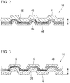
FIG. 2 is a sectional view in a thickness direction showing type A of an in-mold label of the blow-molded container with an in-mold label shown as the embodiment related to the invention. -
FIG. 3 is a sectional view in the thickness direction showing type B of the in-mold label of the blow-molded container with an in-mold label shown as the embodiment related to the invention. -
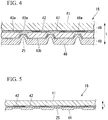
FIG. 4 is a sectional view in the thickness direction showing type C of the in-mold label of the blow-molded container with an in-mold label shown as the embodiment related to the invention. -
FIG. 5 is a sectional view in the thickness direction showing type D of the in-mold label of the blow-molded container with an in-mold label shown as the embodiment related to the invention. -
FIG. 6 is a sectional view of main portions of a molding mold of the blow-molded container with an in-mold label shown as the embodiment related to the invention. -
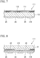
FIG. 7 is a sectional view in a thickness direction showing one form of an in-mold label of a blow-molded container with an in-mold label shown as a comparative example related to the invention. -
FIG. 8 is a sectional view in the thickness direction showing another form of the in-mold label of the blow-molded container with an in-mold label shown as the comparative example related to the invention. - Hereinafter, a blow-molded container 1 with an in-mold label related to an embodiment of the invention will be described with reference to the drawings.
- A blow-molded container 1 with an in-mold label of the present embodiment, as shown in
FIG 1A and 1B , includes acontainer body 15 in which abottom portion 11, abody portion 12, ashoulder portion 13, and amouth portion 14 are continuously provided in this order, and an in-mold label 16 glued on thebody portion 12. - Respective central axes of the
bottom portion 11, thebody portion 12, theshoulder portion 13, and themouth portion 14 in thecontainer body 15 are arranged coaxially with a common axis. Hereinafter, this common axis is referred to as a container axis O, abottom portion 11 side in the direction of the container axis O is referred to as a lower side, and a side opposite to this lower side is referred to as an upper side. Additionally, in a plan view as seen from the direction of the container axis O, a direction orthogonal to the container axis O is referred to as a radial direction, and a direction going around the container axis O is referred to as a circumferential direction. - The
container body 15 is integrally formed of, for example, synthetic resin materials, such as high-density polyethylene resin or polypropylene resin. In addition, thecontainer body 15 has an internal capacity of, for example, about 370 ml. - A peripheral wall portion of the
bottom portion 11 is formed in the shape of a curved surface that protrudes toward a radial outer side, and gradually extends upward from agrounding portion 11a toward the radial outer side. - The
shoulder portion 13 couples an upper end of thebody portion 12 and a lower end of themouth portion 14 together, is formed in the shape of a curved surface that protrudes toward the radial outer side, and gradually extends toward a radial inner side upward from below. - The
body portion 12 extends straight over the entire length in the direction of the container axis O. Additionally thebody portion 12 forms a square shape in whichplanar portions 20 andcorner surfaces - In the shown example, the
body portion 12 forms a rectangular shape in the above cross-sectional view. In addition, thebody portion 12 forms a rectangular shape of which one side is about 75 mm in the above cross-sectional view. Theplanar portions 20 are slightly curved so as to protrude toward the radial outer side. In addition, theplanar portions 20 may extend straight in the above cross-sectional view. - The corner surfaces 21 to 24 are formed in the shape of a curved surface that protrudes toward the radial outer side. In the above cross-sectional view, the curvature radius R of the corner surfaces 21 to 24 is smaller than the curvature radius of the
planar portions 20. - In the present embodiment, in the cross-sectional view of the
body portion 12, when the curvature radius of the corner surfaces 21 to 24 is R (mm) and an angle formed between theplanar portions 20 adjacent to each other around the container axis O is θ (°), R x θ2 is 45000 or more. - In addition, for example, the curvature radius R is about 4 mm to 40 mm, and the angle θ is about 45° to 135°.
- In the shown example, the curvature radius of one corner surface (hereinafter referred to as a maximum corner surface) 21 of the four
corner surfaces 21 to 24 R is greater than that of the other threecorner surfaces 22 to 24, and the curvature radius R of themaximum corner surface 21 is, for example, about 22 mm, the curvature radius R of the other threecorner surfaces 22 to 24 is, for example, about 12.5mm, and the angle θ is, for example, 90° between theplanar portions 20 adjacent to each other around the container axis O. That is, R x θ2 is 178200 in themaximum corner surface 21, and is 101250 in the other threecorner surfaces 22 to 24. - Additionally, the distance from the container axis O in the radial direction is the shortest in the
maximum corner surface 21 among the fourcorner surfaces 21 to 24. - In the shown example, in-
mold labels 16 are respectively glued on portions ranging from themaximum corner surface 21 to respectiveplanar portions 20 continuing on both sides of themaximum corner surface 21 around the container axis O, and portions ranging from the corner surface (hereinafter referred to as an opposite corner surface) 22 that faces themaximum corner surface 21 in the radial direction to respectiveplanar portions 20 continuing on both sides of theopposite corner surface 22 around the container axis O, in an outer peripheral surface of thebody portion 12. Hereinafter, respective portions on which the in-mold labels 16 are glued, in the outer peripheral surface of thebody portion 12, are referred to as glued portions. In addition, the respective in-mold labels 16 are spaced apart from each other in the circumferential direction, and are glued at positions where a portioning line is avoided, in the outer peripheral surfaces of thebody portion 12. -
Multiple recesses 25 are formed on a back surface bonded on the outer peripheral surface of thebody portion 12 out of front and back surfaces of each in-mold label 16 over its whole region. Themultiple recesses 25 are formed with the same shape as each other in a plan view and with the same size as each other, and are arranged at equal intervals on the back surface of the in-mold label 16. Therecesses 25 are formed in a square shape in the plan view, and are arranged on the back surface of the in-mold label 16 in a state where the recesses are aligned so that the portion of the back surface where therecesses 25 are not formed forms a lattice shape in the plan view. In addition, the aspect of the shape or arrangement of therecesses 25 may be appropriately changed without being limited to the present embodiment. - In a state where the in-
mold label 16 is glued on the outer peripheral surface of thebody portion 12, the depth of therecesses 25 is 0.01 mm or more and preferably 0.08 mm or less. - Meanwhile, in a state before the in-
mold label 16 is glued on the outer peripheral surface of thebody portion 12, the depth of therecesses 25 is 0.02 mm or more and preferably 0.10 mm or less, and the total of the internal volumes of all of a plurality ofrecesses 25 that are located in a unit region where a plane area is 1 cm2, in the in-mold label 16, is, for example, about 0.001 cm3 to 0.005 cm3. - In addition, in a case where the depth of the recesses in a state where an in-mold label is glued on the outer peripheral surface of the
body portion 12 exceeds 0.08 mm or in a case where the depth of the recesses in a state before an in-mold label is glued on the outer peripheral surface of thebody portion 12 exceeds 0.10 mm, when in-mold labels are automatically supplied into a cavity C using a device, multiple sheets of bundled in-mold labels may not be able to be suctioned and taken out sheet by sheet, or printing to be performed on an in-mold label may become unclear, or portions except the recesses in an in-mold label may be reversed at the time of gluing onto the container body, may protrude to a front surface side of this label, and may damage the external appearance of a blow-molded container with an in-mold label. - Additionally, when the tensile elasticity of the in-
mold label 16 is E (MPa) and the thickness of the in-mold label 16 is t (mm), E x t3 satisfies 0.20 or less, and preferably, 0.05 or more, the number of therecesses 25 that are located in a unit region where a plane area is 1 cm2, in an in-mold label 16, is for example, about 25 pieces to 2500 pieces, and the proportion of the total plane area occupied by themultiple recesses 25 of the in-mold label 16 is 10% or more and preferably 70% or less. - In addition, the thickness t of the in-
mold label 16 is, for example, about 0.04 mm to 0.10 mm. Additionally, the tensile elasticity E is, for example, about 110 MPa to 250 MPa. - Here, if E x t3 is less than 0.05, the rigidity of an in-mold label becomes two weak, the handling thereof becomes difficult, and the in-mold label is not easily set in
molds - In addition, the thickness t of the in-
mold label 16 was obtained by measuring portions of thelabel 16 where therecesses 25 are not formed. Additionally, the tensile elasticity E was measured by pulling a test piece, which is obtained by forming the in-mold label 16 in a shape based on ASTM D-1822-L, at a speed of 1 mm/1 minute. - Additionally, the numerical value of E x t3, the number of the
recesses 25 included in the above unit region, and the proportion of the total plane area of themultiple recesses 25 that occupies the plane area of the in-mold label 16 do not vary substantially before and after the in-mold label 16 is glued on thebody portion 12. - Additionally, through-holes (not shown) are discontinuously over the entire length in the direction of the container axis O in corresponding
portions 16a glued on respective outer peripheral surfaces of themaximum corner surface 21 and theopposite corner surface 22 of thebody portion 12 in each in-mold label 16. - Here, the in-
mold label 16 includes the following four types of, for example, type A, type B, type C, and type D. - In the in-
mold label 16 of type A, as is shown inFIG. 2 , a transparentbase material layer 41 consisting of a non-extended cast film made of polypropylene resin, aprinting layer 42, ananchor coat layer 43, and aglue layer 44 made of low-density polyethylene resin are laminated in this order from a front surface side toward a back surface side. In addition, the in-mold label 16 is formed so as to be sequentially laminated from the front surface side toward the back surface side. - The
printing layer 42 is formed by, for example, gravure printing, screen printing, or flexographic printing being performed on a back surface side of thebase material layer 41. Theanchor coat layer 43 is formed of, for example, materials obtained by diluting polyethyleneimine, polyetherpolyol polysiocyanate, or polyesterpolyol polysiocyanate with water or an organic solvent. Theglue layer 44 is formed by, for example, an extrusion laminating method being performed on a back surface side of theanchor coat layer 43. Additionally, therecesses 25 are formed by performing embossing in a back surface of theglue layer 44 after theglue layer 44 is cooled and solidified with a cooling roller. In this case, the recesses are formed not only in theglue layer 44 but also in the respective back surfaces of thebase material layer 41, theprinting layer 42, and theanchor coat layer 43, and protrusions are formed in the respective front surfaces of thebase material layer 41, theprinting layer 42, theanchor coat layer 43, and theglue layer 44 in correspondence with the recesses. - In addition, the thickness of the
base material layer 41 is about 0.070 mm, and the thickness of theglue layer 44 is about 0.010 mm. - In the in-
mold label 16 of type B, as is shown inFIG. 3 , aprotective layer 45 made of low-density polypropylene resin, theanchor coat layer 43, theprinting layer 42, and aglue layer 46 consisting of a non-extended cast film made of polyethylene resin are laminated in this order from a front surface side toward a back surface side. In addition, the in-mold label 16 is formed so as to be sequentially laminated from the back surface side toward the front surface side. Theprotective layer 45 is formed by, for example, an extrusion laminating method being performed on front surface side of theanchor coat layer 43. - Additionally, the
recesses 25 are formed by performing embossing in a back surface of theglue layer 46 after theprotective layer 45 is cooled and solidified with a cooling roller. - In this case, the recesses are formed not only in the
glue layer 46 but also in the respective back surfaces of theprotective layer 45, theanchor coat layer 43, and theprinting layer 42, and protrusions are formed in the respective front surfaces of theprotective layer 45, theanchor coat layer 43, theprinting layer 42, and theglue layer 46 which are in correspondence with the recesses. - In addition, the thickness of the
protective layer 45 is about 0.010 mm, and the thickness of theglue layer 46 is about 0.070 mm. - In the in-
mold label 16 of type C, as is shown inFIG. 4 , thebase material layer 41, theprinting layer 42, a firstanchor coat layer 43a, anextrusion resin layer 47 made of low-density polyethylene resin, a secondanchor coat layer 43b, theglue layer 46 consisting of a non-extended cast film made of polypropylene resin are laminated in this order from a front surface side toward a back surface side. - The
recesses 25 formed in the back surface of theglue layer 46 reach a front surface of theglue layer 46, front and back surfaces of the secondanchor coat layer 43b, and even a back surface of theextrusion resin layer 47, and a front surface of theextrusion resin layer 47, the firstanchor coat layer 43a, theprinting layer 42, and thebase material layer 41 are flat. - In addition, the in-
mold label 16 is formed by the flatextrusion resin layer 47 in a softened state being sandwiched between afirst film 48 including thebase material layer 41, theprinting layer 42, and the firstanchor coat layer 43a and asecond film 49 including theglue layer 46 where therecesses 25 are formed and the secondanchor coat layer 43b and byprojection portions 49a corresponding to therecesses 25 on the front surface side of thesecond film 49 being recessed into theextrusion resin layer 47. - Additionally, the first and second anchor coat layers 43a and 43b are formed of the same materials as the
anchor coat layer 43 in type A and type B. - In addition, the thickness of the
base material layer 41 is about 0.030 mm, and the thickness of theglue layer 46 is about 0.050 mm. - In the in-
mold label 16 of type D, as is shown inFIG. 5 , the transparentbase material layer 41, theprinting layer 42, theanchor coat layer 43, and theglue layer 44 made of low-density polyethylene resin are laminated in this order from a front surface side toward a back surface side. - The depth of the
recesses 25 falls within a thickness range of theglue layer 44, and thebase material layer 41, theprinting layer 42, and theanchor coat layer 43 are flat. - In addition, the in-
mold label 16 is formed so as to be sequentially laminated from the front surface side toward the back surface side. - The
recesses 25 are formed simultaneously when an embossing roll is made to abut against and cool the back surface of theglue layer 44 after theglue layer 44 is formed with a thickness of, or example, about 0.005 mm to 0.030 mm by forming, for example, an extrusion laminating method on a back surface of theanchor coat layer 43. - In addition, the thickness of the
base material layer 41 is about 0.040 mm, and the thickness of theglue layer 44 is about 0.020 mm. - Additionally, in the in-
mold labels 16 of types A, C, and D, the thickness of thebase material layer 41 is, for example, about 0.03 mm to 0.08 mm. - Next, a
molding mold 30 for manufacturing the blow-molded container 1 with an in-mold label configured as described above will be described with reference toFIG. 6 . - The
molding mold 30 includes an extruder (not shown) that extrusion-molds a cylindrical parison (preliminary molded body) W, and a pair ofmolds container body 15 to be molded, formed betweenmold surfaces - In the shown example, the pair of
molds corner surfaces mold labels 16 are not glued are located, among two sets of diagonal portions in thebody portion 12 of thecontainer body 15. First andsecond intake passages molds second intake passages maximum corner surface 21 of thebody portion 12 of thecontainer body 15, portions C2 that form the pair ofplanar portions 20 continuing on themaximum corner surface 21 in the circumferential direction, a portion C3 that forms theopposite corner surface 22, and portions C4 that form the pair ofplanar portions 20 continuing on theopposite corner surface 22 in the circumferential direction, in the inner surface of the cavity C. Thefirst intake passages 33, which open to the portion C1 that forms themaximum corner surface 21 and the portion C3 that forms theopposite corner surface 22, in the inner surface of the cavity C, among the first andsecond intake passages mold labels 16 over the substantially entire length thereof in the direction of the container axis O to be suctioned therethrough. - Here, the length, in the direction of the container axis O, of the in-
mold labels 16 suctioned by thefirst intake passages 33 may not be the entire length of the in-mold labels 16 in the direction of the container axis O as long as the length is such that the position of thecorresponding portions 16a of the in-mold labels 16 with respect to the inner surface of the cavity C can be fixed in blow molding to be described below. - Next, a method for manufacturing the blow-molded container 1 with an in-mold label using the
molding mold 30 configured as described above will be described. - First, an in-
mold label 16 is integrally arranged from the portion C1 that forms themaximum corner surface 21 to the portions C2 that form the pair ofplanar portions 20 continuing on themaximum corner surface 21 in the circumferential direction, in the inner surface of the cavity C of themolds mold label 16 that is separate from the above in-mold label is integrally arranged from the portion C3 that forms theopposite corner surface 22 to the portions C4 that form the pair ofplanar portions 20 continuing on theopposite corner surface 22 in the circumferential direction, in the inner surface of the cavity C of themolds mold labels 16 are stuck on the inner surface of the cavity C by applying a negative pressure to the respective in-mold labels 16 through the first andsecond intake passages portion 16a, which is located in the portion C1 that forms themaximum corner surface 21 in the inner surface of the cavity C, and thecorresponding portion 16a, which is located in the portion C3 that forms theopposite corner surface 22 in the inner surface of the cavity C, in the respective in-mold labels 16, are suctioned toward the inner surface of the cavity C over the substantially entire length thereof in the direction of the container axis O. - Then, the cylindrical parison W extrusion-molded from the extruder (not shown) is sandwiched between the pair of
molds - Next, the
container body 15 is formed by blow-molding the parison W in a state where the pair ofmolds mold labels 16 are glued on the outer peripheral surface of the body portion 12 (blow molding process). In this process, a state where a negative pressure is applied to the in-mold labels 16 and the in-mold labels are stick on the inner surface of the cavity C are maintained. Additionally, in this case, the parison W is expanded and deformed only in the radial direction. - As described above, according to the blow-molded container 1 with an in-mold label and its manufacturing method related to the present embodiment, the
multiple recesses 25 are formed on the back surfaces of the in-mold labels 16. Thus, when the in-mold labels 16 bends, the volume of therecesses 25 located in these portions decreases. Therefore, not only it becomes easy to make the in-mold labels 16 conform to the external shape of the above glued portions of thebody portion 12, but also thelabels 16 can be inhibited from thermally contracting when the in-mold labels 16 are heated due to the temperature of the parison W. - From above, when the in-
mold labels 16 are glued on the outer peripheral surfaces of the above glued portions, the in-mold labels can be naturally deformed along the above glued portions, and the in-mold labels 16 can be glued on the above glued portions without causing air collection between the in-mold labels and the corner surfaces 21 and 22. - Particularly, in the cross-sectional view in the above glued portions, when the curvature radius of the corner surfaces 21 and 22 is R (mm) and the angle formed between the
planar portions 20 adjacent to each other around the container axis O mutually make is θ (°), R x θ2 is 45000 or more, and the curvature radius R of the corner surfaces 21 and 22 becomes greater as the angle 0 formed between theplanar portions 20 adjacent to each other around the container axis O becomes a smaller acute angle. Thus, the corner surfaces 21 and 22 gently bend in the above cross-sectional view, and a long length thereof in the circumferential direction is easily secured, and it is possible to easily deform the in-mold labels 16 along the outer peripheral surfaces of the above glued portions, and air collection can be reliably inhibited from occurring in thelabels 16 at the time of the gluing of the in-mold labels 16. - Additionally, the
multiple recesses 25 are formed in the back surfaces of the in-mold labels 16. Thus, in blow molding, not only the air between thecontainer body 15 or the parison W and the in-mold labels 16 are easily escaped to the outside through therecesses 25, but also it is possible to house the air, which could not have escaped, within therecesses 25, and occurrence of air collection can be more reliably suppressed. - Additionally, since the proportion of the total plane area occupied by the
multiple recesses 25 of the in-mold labels 16 is 10% or more, the depth of therecesses 25 is 0.02 mm or more in a state before the in-mold labels 16 are glued on the outer peripheral surface of thebody portion 12 or is 0.01 mm or more in a state where the in-mold labels are glued, air collection can be reliably made difficult to occur between the corner surfaces 21 and 22 and the in-mold labels 16. - Additionally, since the corresponding
portions 16a of the in-mold labels 16 are stuck on the inner surface of the cavity C in the blow molding process, the positions of thecorresponding portions 16a to the inner surface of the cavity C are fixed in the blow molding process. As a result, air collection can be more reliably inhibited from occurring between the corner surfaces 21 and 22 and the in-mold labels 16. - Next, a verification test of the working effects described above will be described.
- In this test, in-
mold labels 111 of type E and type F were adopted in addition to the in-mold labels 16 of the aforementioned type A to type D. - The in-
mold label 111 of type E, as shown inFIG. 7 , includes abase material layer 112 made of synthetic paper, aprinting layer 113 formed by flexographic printing being performed on the surface of thebase material layer 112, aprotective layer 117 made of transparent varnish that covers theprinting layer 113, and aglue layer 116 consisting of a heat-sealing layer arranged on a back surface of thebase material layer 112. The depth of therecesses 25 falls within the thickness range of theglue layer 116. - In addition, the thickness of the
base material layer 112 is about 0.080 mm. The in-mold label 111 of F type, as shown inFIG. 8 , is formed such that thebase material layer 41, theprinting layer 42 formed by gravure printing being performed on the back surface of thebase material layer 41, theanchor coat layer 43, adry lamination layer 115, aglue layer 118 made of copolymerized polypropylene resin are laminated in this order toward a back surface side from a front surface side. The depth of therecesses 25 falls within the thickness range of theglue layer 118. - In addition, the thickness of the
base material layer 41 is about 0.060 mm, and the thickness of theglue layer 118 is about 0.030 mm. - The configuration of the in-
mold labels - In Table 1, "Thickness" shows the thickness of portions where the
recesses 25 are not formed in the in-mold labels recesses 25, "Plane Area Proportion" shows the proportion of the total plane area occupied by themultiple recesses 25 of the in-mold labels recesses 25 that are located in a unit region where a plane area is 1 cm2, in the in-mold labels recesses 25 that are located in the unit region where the plane area is 1 cm2, in the in-mold labels [Table 1] Type Thickness Before Gluing t (mm) Depth (mm) Plane Area Proportion (%) Number of Pieces (Pieces/1 cm2) Internal Volume Before Gluing (cm3/1 cm2) E x t3 (MPa·mm3) Material of Container Body Before Gluing After Gluing Container Axial Direction Circumferential Direction A 0.085 0.060 0.030 46 324 0.00200 0.142 0.130 High-Density Polyethylene B 0.085 0.075 0.040 46 324 0.00250 0.150 0.145 Polypropylene C 0.095 0.040 0.025 46 324 0.00130 0.124 0.096 Polypropylene D 0.065 0.020 0.015 46 324 0.00110 0.073 0.068 High-Density Polyethylene E 0.090 0.010 less than 0.010 30 400 0.00020 0.536 0.283 Polypropylene F 0.095 0.015 less than 0.010 25 400 0.00030 0.378 0.339 High-Density Polyethylene - At least one of the type of the in-
mold labels first intake passages 33 in themolds mold labels - The results are shown in Table 2.
- In Table 2, cases where the evaluation results are O show that air collection could not be visually recognized in the in-
mold labels [Table 2] Angle θ (°) Radius of Curvature R (mm) R x θ2 Type of In-Mold Label Presence/Absence of First Intake Passage Evaluation Result Example 1 110 6.0 72600 A Yes O Example 2 90 12.5 101250 A Yes O Example 3 60 12.5 45000 A Yes O Example 4 110 6.0 72600 B Yes O Example 5 90 12.5 101250 B Yes O Example 6 60 12.5 45000 B Yes O Example 7 110 6.0 72600 C Yes O Example 8 90 12.5 101250 C Yes O Example 9 60 12.5 45000 C Yes O Example 10 110 6.0 72600 D Yes O Example 11 90 12.5 101250 D Yes O Example 12 60 12.5 45000 D Yes O Example 13 110 6.0 72600 A No Δ Example 14 90 12.5 101250 A No Δ Comparative Example 1 90 5.0 40500 A Yes x Comparative Example 2 60 6.0 21600 A Yes x Comparative Example 3 110 6.0 72600 E Yes x Comparative Example 4 90 12.5 101250 E Yes x Comparative Example 5 110 6.0 72600 F Yes x Comparative Example 6 90 12.5 101250 F Yes x - As a result, in the blow-molded containers 1 with an in-mold label including the in-
mold labels 16 of type A to D and thecontainer body 15 in which E x t3 is 0.20 or less and R x θ2 is 45000 or more, it was confirmed that air collection does not occur in the in-mold labels 16, or external appearance quality is not influenced even if air collection occurs. - The invention is not limited to the above embodiment, and can be appropriately changed without departing from the concept of the invention.
- For example, in the above embodiment, the in-
mold labels 16 are respectively glued on the portions ranging from themaximum corner surface 21 to the respectiveplanar portions 20 continuing on both sides of themaximum corner surface 21 around the container axis O, and the portions ranging from theopposite corner surface 22 to the respectiveplanar portions 20 continuing on both sides of theopposite corner surface 22 around the container axis O, in the outer peripheral surface of thebody portion 12. However, instead of this, the in-mold labels may be limitedly glued on the portions ranging from one of the corner surfaces 21 and 22 to the respectiveplanar portions 20 continuing on both sides of this corner surface around the container axis O, in the outer peripheral surface of thebody portion 12. - Additionally, in the above embodiment, the curvature radius R of one
corner surface 21 among the fourcorner surfaces 21 to 24 is made greater than that of the other threecorner surfaces 22 to 24. However, the curvature radii R of all the fourcorner surfaces 21 to 24 may be altogether made equal to each other, and may be altogether make different from each other. - Additionally, instead of the above embodiment, the pair of
molds planar portions 20 that face each other in thebody portion 12 of thecontainer body 15, and the in-mold labels 16 may be glued on the portions ranging to the respective corner surfaces 21 to 24 continuing on both sides of theplanar portions 20 around the container axis O at the positions where the portioning line is avoided, in the outer peripheral surface of thebody portion 12. In addition, in this blow-molded container with an in-mold label, the portioning line may be located at central portions of theplanar portions 20 around the container axis O. - Additionally, the cross-sectional view shape of the
body portion 12 orthogonal to the container axis O is not limited to the rectangular shape, and may be other angular shapes. - Additionally, in the above embodiment, the
body portion 12 is formed in a prismatic shape. However, the shape of the body portion may be appropriately changed to, for example, a pyramidal shape, a truncated pyramidal shape, or the like. - Additionally, the thickness of the in-
mold labels 16, the depth of therecesses 25, or the like is not limited to the above embodiment, and may be appropriately changed. - In addition, the constituent elements in the above embodiment can be substituted with well-known constituent elements without departing from the concept of the invention, and the above modification examples may be appropriately combined together.
- According to the invention, a blow-molded container with an in-mold label in which air collection does not easily occur between the corner surfaces and the in-mold labels can be manufactured.
-
- 1:
- BLOW-MOLDED CONTAINER WITH IN-MOLD LABEL
- 11:
- BOTTOM PORTION
- 11a:
- GROUNDING PORTION
- 12:
- BODY PORTION
- 13:
- SHOULDER PORTION
- 14:
- MOUTH PORTION
- 15:
- CONTAINER BODY
- 16,111:
- IN-MOLD LABEL
- 16a:
- CORRESPONDING PORTION
- 20:
- PLANAR PORTION
- 21,22,23,24:
- CORNER SURFACE
- 25:
- RECESS
- 30:
- MOLDING MOLD
- 31, 32:
- MOLD
- 31a, 32a:
- MOLD SURFACE
- 33:
- FIRST INTAKE PASSAGE
- 34:
- SECOND INTAKE PASSAGE
- 41, 112:
- BASE MATERIAL LAYER
- 42, 113:
- PRINTING LAYER
- 43:
- ANCHOR COAT LAYER
- 44,46,116,118:
- GLUE LAYER
- 45,117:
- PROTECTIVE LAYER
- 47:
- EXTRUSION RESIN LAYER
- 48:
- FIRST FILM
- 49:
- SECOND FILM
- 115:
- DRY LAMINATION LAYER
- C:
- CAVITY
- O:
- CONTAINER AXIS
- W:
- PARISON (PRELIMINARY MOLDED BODY)
Claims (5)
- A blow-molded container with an in-mold label, comprising:a container body having a body portion that forms a square shape in which planar portions and corner surfaces are alternately and continuously provided around a container axis, in a cross-sectional view orthogonal to the container axis; andin-mold labels, which are integrally glued on outer peripheral surfaces of glued portions, ranging from the corner surfaces to the respective planar portions continuing on both sides of the corner surfaces around the container axis, in the body portion,wherein, among front and back surfaces of the in-mold labels, multiple recesses are formed over the entire back surfaces, which are glued to the outer peripheral surfaces of the glued portions,wherein, when the tensile elasticity of the in-mold labels is E (MPa) and the thickness of the in-mold labels is t (mm), E x t3 is 0.20 or less, andwherein, when the radius of curvature of the corner surfaces is R (mm) and the angle formed between the planar portions is θ (°) in a cross-sectional view of the glued portions, R x θ2 is 45000 or more.
- The blow-molded container with an in-mold label according to Claim 1,
wherein the depth of the recesses is 0.01 mm or more, and the proportion of the total plane area occupied by the multiple recesses of the in-mold labels is 10% or more. - A method for manufacturing a blow-molded container with an in-mold label including
a container body having a body portion that forms a square shape in which planar portions and corner surfaces are alternately and continuously provided around a container axis, in a cross-sectional view orthogonal to the container axis; and
in-mold labels, which are integrally glued on outer peripheral surfaces of glued portions, ranging from the corner surfaces to the respective planar portions continuing on both sides of the corner surfaces around the container axis, in the body portion, the method comprising:a setting process of arranging a preliminary molded body and the in-mold labels within a cavity; anda blow-molding process of blow-molding the preliminary molded body to form the container body and gluing the in-mold labels on the outer peripheral surfaces of the glued portions,wherein, among front and back surfaces of the in-mold labels, multiple recesses are formed over the entire back surfaces, which are glued to the outer peripheral surfaces of the glued portions,wherein, when the tensile elasticity of the in-mold labels is E (MPa) and the thickness of the in-mold labels is t (mm), E x t3 satisfies 0.20 or less, andwherein, when the radius of curvature of the corner surfaces is R (mm) and an angle formed between the planar portions is 0 (°) in a cross-sectional view of the glued portions, R x θ2 is 45000 or more. - The method for manufacturing a blow-molded container with an in-mold label according to Claim 3,
wherein the proportion of the total plane area occupied by the multiple recesses of the in-mold labels is 10% or more, and the depth of the recesses is 0.02 mm or more in a state before the in-mold labels are glued on an outer peripheral surface of the body portion. - The method for manufacturing a blow-molded container with an in-mold label according to Claim 3 or 4,
wherein corresponding portions glued on outer peripheral surfaces of the corner surface in the in-mold labels are stuck on an inner surface of the cavity in the blow molding process.
Applications Claiming Priority (2)
| Application Number | Priority Date | Filing Date | Title |
|---|---|---|---|
| JP2014093547A JP2015209247A (en) | 2014-04-30 | 2014-04-30 | Blow container with in-mold label and method for producing blow container with in-mold label |
| PCT/JP2015/056711 WO2015166709A1 (en) | 2014-04-30 | 2015-03-06 | Blow-molded container with in-mold label and method for manufacturing blow-molded container with in-mold label |
Publications (3)
| Publication Number | Publication Date |
|---|---|
| EP3138681A1 true EP3138681A1 (en) | 2017-03-08 |
| EP3138681A4 EP3138681A4 (en) | 2018-01-03 |
| EP3138681B1 EP3138681B1 (en) | 2018-12-05 |
Family
ID=54358450
Family Applications (1)
| Application Number | Title | Priority Date | Filing Date |
|---|---|---|---|
| EP15786172.5A Active EP3138681B1 (en) | 2014-04-30 | 2015-03-06 | Blow-molded container with in-mold label and method for manufacturing blow-molded container with in-mold label |
Country Status (5)
| Country | Link |
|---|---|
| US (1) | US10118734B2 (en) |
| EP (1) | EP3138681B1 (en) |
| JP (1) | JP2015209247A (en) |
| AU (1) | AU2015254413B2 (en) |
| WO (1) | WO2015166709A1 (en) |
Families Citing this family (2)
| Publication number | Priority date | Publication date | Assignee | Title |
|---|---|---|---|---|
| JP6837720B2 (en) * | 2017-05-31 | 2021-03-03 | 株式会社吉野工業所 | Manufacturing method of in-mold labeled container and in-mold labeled container |
| JP2020050371A (en) * | 2018-09-26 | 2020-04-02 | 大日本印刷株式会社 | Polygonal in-mold container |
Family Cites Families (22)
| Publication number | Priority date | Publication date | Assignee | Title |
|---|---|---|---|---|
| JP2766487B2 (en) * | 1988-10-18 | 1998-06-18 | 株式会社吉野工業所 | Labeling method for plowed containers |
| JPH0661830B2 (en) | 1988-11-17 | 1994-08-17 | 東洋製罐株式会社 | How to make a labeled hollow container |
| JP3140075B2 (en) * | 1991-03-04 | 2001-03-05 | 株式会社ユポ・コーポレーション | In-mold label |
| JP2710258B2 (en) * | 1991-10-09 | 1998-02-10 | 東洋製罐株式会社 | Blow molded bottle with in-mold label |
| JPH0664029A (en) * | 1992-08-21 | 1994-03-08 | Toppan Printing Co Ltd | Bottle with cardboard label and manufacturing method thereof |
| US5344305A (en) * | 1993-02-01 | 1994-09-06 | Ccl Label, Inc. | Apparatus for in-mold labelling |
| US5968443A (en) * | 1996-03-01 | 1999-10-19 | The Clorox Company | Process for in-mold labelling |
| JPH10175625A (en) * | 1996-12-17 | 1998-06-30 | Toyo Seikan Kaisha Ltd | Square plastic bottle |
| JP3781161B2 (en) * | 1999-03-05 | 2006-05-31 | イーストスリーテクノロジー株式会社 | Blow molded product manufacturing method and blow molded product |
| JP2001353770A (en) * | 2000-06-16 | 2001-12-25 | Yupo Corp | Label for in-mold molding and resin molded product with the label |
| US20040026438A1 (en) * | 2002-08-12 | 2004-02-12 | Lori Tyra | Article of manufacture with in-molded erasable and markable discrete surface structure and method of manufacture |
| JP2004136486A (en) | 2002-10-16 | 2004-05-13 | Dainippon Printing Co Ltd | In-mold label molding label, in-mold label biaxially stretched blow molded product, and method for producing the same. |
| JP4754183B2 (en) * | 2004-05-19 | 2011-08-24 | 有限会社K・Mプランニング | Ribbed in-mold label container and manufacturing method thereof |
| JP5037485B2 (en) * | 2005-03-16 | 2012-09-26 | シーカ・テクノロジー・アーゲー | Setting and curing accelerators for hydraulic binders, methods of use thereof, and methods of making the same |
| JP2009064295A (en) * | 2007-09-07 | 2009-03-26 | Tdk Corp | Intermediate for touch switch, die for in-mold molding, and method to manufacture intermediate for touch switch |
| JP5168554B2 (en) * | 2008-03-31 | 2013-03-21 | 株式会社吉野工業所 | Thin container with in-mold label |
| JP5554576B2 (en) * | 2010-01-22 | 2014-07-23 | Kisco株式会社 | In-mold label |
| JP5660431B2 (en) * | 2010-05-31 | 2015-01-28 | 株式会社吉野工業所 | Labeled container |
| JP5943247B2 (en) * | 2010-11-30 | 2016-07-05 | 株式会社吉野工業所 | Cup-shaped container |
| EP2468643A1 (en) * | 2010-12-23 | 2012-06-27 | KPSS-Kao Professional Salon Services GmbH | Container having a labeled textured surface |
| JP6103343B2 (en) * | 2012-04-27 | 2017-03-29 | 株式会社吉野工業所 | In-mold forming label and labeled container |
| TW201416214A (en) * | 2012-10-26 | 2014-05-01 | Etansi Inc | Decoration film, decorated molded device and decoration molding process |
-
2014
- 2014-04-30 JP JP2014093547A patent/JP2015209247A/en active Pending
-
2015
- 2015-03-06 AU AU2015254413A patent/AU2015254413B2/en active Active
- 2015-03-06 US US15/127,935 patent/US10118734B2/en active Active
- 2015-03-06 EP EP15786172.5A patent/EP3138681B1/en active Active
- 2015-03-06 WO PCT/JP2015/056711 patent/WO2015166709A1/en not_active Ceased
Also Published As
| Publication number | Publication date |
|---|---|
| JP2015209247A (en) | 2015-11-24 |
| EP3138681B1 (en) | 2018-12-05 |
| WO2015166709A1 (en) | 2015-11-05 |
| US20170107016A1 (en) | 2017-04-20 |
| AU2015254413B2 (en) | 2019-07-04 |
| AU2015254413A1 (en) | 2016-10-13 |
| US10118734B2 (en) | 2018-11-06 |
| EP3138681A4 (en) | 2018-01-03 |
Similar Documents
| Publication | Publication Date | Title |
|---|---|---|
| US10019914B2 (en) | In-mold labels and a labeled container | |
| JP5150433B2 (en) | Laminated film processing method | |
| TWI552928B (en) | Labeled blow molding container | |
| EP3138681B1 (en) | Blow-molded container with in-mold label and method for manufacturing blow-molded container with in-mold label | |
| CN1890156B (en) | Molded container and apparatus for manufacturing the same | |
| WO2020056702A1 (en) | Paper container package and manufacturing method therefor | |
| KR20130064715A (en) | Container with label | |
| ES2720154T3 (en) | Heat shrinkable polymer label based on unidirectional oriented polyethylene | |
| CN104640776A (en) | Labeled hollow formed container and forming method thereof | |
| TW202110613A (en) | In mold label, method for manufacturing in-mold label, container provided with in-mold label, and method for manufacturing container provided with in-mold label | |
| CN108602580A (en) | Laminated sheets and packaging container sleeves | |
| BR112016019536B1 (en) | PACKAGING MATERIAL, ITS USE AND TRAINING METHOD | |
| TWI713900B (en) | Paper container package and method for manufacturing the same | |
| JP6577117B2 (en) | In-mold forming label and labeled container | |
| JP5182660B2 (en) | Thin container with in-mold label | |
| JP6096630B2 (en) | Blow molding container with in-mold label | |
| US20080053608A1 (en) | Two-ply pre-printed rigid thermoformable material | |
| JP6437190B2 (en) | In-mold forming label and labeled container | |
| JP2015224065A (en) | Packaging film having impact-resistant characteristic and high rigidity | |
| JP2014084129A (en) | Protective film | |
| WO2021077376A1 (en) | Novel environment-friendly paper bag body |
Legal Events
| Date | Code | Title | Description |
|---|---|---|---|
| STAA | Information on the status of an ep patent application or granted ep patent |
Free format text: STATUS: THE INTERNATIONAL PUBLICATION HAS BEEN MADE |
|
| PUAI | Public reference made under article 153(3) epc to a published international application that has entered the european phase |
Free format text: ORIGINAL CODE: 0009012 |
|
| STAA | Information on the status of an ep patent application or granted ep patent |
Free format text: STATUS: REQUEST FOR EXAMINATION WAS MADE |
|
| 17P | Request for examination filed |
Effective date: 20160926 |
|
| AK | Designated contracting states |
Kind code of ref document: A1 Designated state(s): AL AT BE BG CH CY CZ DE DK EE ES FI FR GB GR HR HU IE IS IT LI LT LU LV MC MK MT NL NO PL PT RO RS SE SI SK SM TR |
|
| AX | Request for extension of the european patent |
Extension state: BA ME |
|
| DAV | Request for validation of the european patent (deleted) | ||
| DAX | Request for extension of the european patent (deleted) | ||
| A4 | Supplementary search report drawn up and despatched |
Effective date: 20171201 |
|
| RIC1 | Information provided on ipc code assigned before grant |
Ipc: B65D 23/08 20060101ALN20171127BHEP Ipc: B29C 49/24 20060101AFI20171127BHEP Ipc: B65D 23/00 20060101ALI20171127BHEP Ipc: B29K 105/00 20060101ALN20171127BHEP Ipc: B29L 31/00 20060101ALN20171127BHEP Ipc: B65D 1/02 20060101ALI20171127BHEP Ipc: B29K 23/00 20060101ALN20171127BHEP |
|
| GRAP | Despatch of communication of intention to grant a patent |
Free format text: ORIGINAL CODE: EPIDOSNIGR1 |
|
| STAA | Information on the status of an ep patent application or granted ep patent |
Free format text: STATUS: GRANT OF PATENT IS INTENDED |
|
| RIC1 | Information provided on ipc code assigned before grant |
Ipc: B65D 23/08 20060101ALN20180528BHEP Ipc: B29C 49/24 20060101AFI20180528BHEP Ipc: B65D 1/02 20060101ALI20180528BHEP Ipc: B29K 105/00 20060101ALN20180528BHEP Ipc: B29K 23/00 20060101ALN20180528BHEP Ipc: B29L 31/00 20060101ALN20180528BHEP Ipc: B65D 23/00 20060101ALI20180528BHEP |
|
| INTG | Intention to grant announced |
Effective date: 20180613 |
|
| RIC1 | Information provided on ipc code assigned before grant |
Ipc: B29L 31/00 20060101ALN20180604BHEP Ipc: B29K 105/00 20060101ALN20180604BHEP Ipc: B29K 23/00 20060101ALN20180604BHEP Ipc: B65D 23/08 20060101ALN20180604BHEP Ipc: B29C 49/24 20060101AFI20180604BHEP Ipc: B65D 1/02 20060101ALI20180604BHEP Ipc: B65D 23/00 20060101ALI20180604BHEP |
|
| GRAS | Grant fee paid |
Free format text: ORIGINAL CODE: EPIDOSNIGR3 |
|
| GRAA | (expected) grant |
Free format text: ORIGINAL CODE: 0009210 |
|
| STAA | Information on the status of an ep patent application or granted ep patent |
Free format text: STATUS: THE PATENT HAS BEEN GRANTED |
|
| AK | Designated contracting states |
Kind code of ref document: B1 Designated state(s): AL AT BE BG CH CY CZ DE DK EE ES FI FR GB GR HR HU IE IS IT LI LT LU LV MC MK MT NL NO PL PT RO RS SE SI SK SM TR |
|
| REG | Reference to a national code |
Ref country code: GB Ref legal event code: FG4D |
|
| REG | Reference to a national code |
Ref country code: CH Ref legal event code: EP |
|
| REG | Reference to a national code |
Ref country code: AT Ref legal event code: REF Ref document number: 1072487 Country of ref document: AT Kind code of ref document: T Effective date: 20181215 |
|
| REG | Reference to a national code |
Ref country code: IE Ref legal event code: FG4D |
|
| REG | Reference to a national code |
Ref country code: DE Ref legal event code: R096 Ref document number: 602015021023 Country of ref document: DE |
|
| REG | Reference to a national code |
Ref country code: NL Ref legal event code: MP Effective date: 20181205 |
|
| REG | Reference to a national code |
Ref country code: AT Ref legal event code: MK05 Ref document number: 1072487 Country of ref document: AT Kind code of ref document: T Effective date: 20181205 |
|
| REG | Reference to a national code |
Ref country code: LT Ref legal event code: MG4D |
|
| PG25 | Lapsed in a contracting state [announced via postgrant information from national office to epo] |
Ref country code: ES Free format text: LAPSE BECAUSE OF FAILURE TO SUBMIT A TRANSLATION OF THE DESCRIPTION OR TO PAY THE FEE WITHIN THE PRESCRIBED TIME-LIMIT Effective date: 20181205 Ref country code: LT Free format text: LAPSE BECAUSE OF FAILURE TO SUBMIT A TRANSLATION OF THE DESCRIPTION OR TO PAY THE FEE WITHIN THE PRESCRIBED TIME-LIMIT Effective date: 20181205 Ref country code: NO Free format text: LAPSE BECAUSE OF FAILURE TO SUBMIT A TRANSLATION OF THE DESCRIPTION OR TO PAY THE FEE WITHIN THE PRESCRIBED TIME-LIMIT Effective date: 20190305 Ref country code: AT Free format text: LAPSE BECAUSE OF FAILURE TO SUBMIT A TRANSLATION OF THE DESCRIPTION OR TO PAY THE FEE WITHIN THE PRESCRIBED TIME-LIMIT Effective date: 20181205 Ref country code: BG Free format text: LAPSE BECAUSE OF FAILURE TO SUBMIT A TRANSLATION OF THE DESCRIPTION OR TO PAY THE FEE WITHIN THE PRESCRIBED TIME-LIMIT Effective date: 20190305 Ref country code: HR Free format text: LAPSE BECAUSE OF FAILURE TO SUBMIT A TRANSLATION OF THE DESCRIPTION OR TO PAY THE FEE WITHIN THE PRESCRIBED TIME-LIMIT Effective date: 20181205 Ref country code: LV Free format text: LAPSE BECAUSE OF FAILURE TO SUBMIT A TRANSLATION OF THE DESCRIPTION OR TO PAY THE FEE WITHIN THE PRESCRIBED TIME-LIMIT Effective date: 20181205 Ref country code: FI Free format text: LAPSE BECAUSE OF FAILURE TO SUBMIT A TRANSLATION OF THE DESCRIPTION OR TO PAY THE FEE WITHIN THE PRESCRIBED TIME-LIMIT Effective date: 20181205 |
|
| PG25 | Lapsed in a contracting state [announced via postgrant information from national office to epo] |
Ref country code: RS Free format text: LAPSE BECAUSE OF FAILURE TO SUBMIT A TRANSLATION OF THE DESCRIPTION OR TO PAY THE FEE WITHIN THE PRESCRIBED TIME-LIMIT Effective date: 20181205 Ref country code: AL Free format text: LAPSE BECAUSE OF FAILURE TO SUBMIT A TRANSLATION OF THE DESCRIPTION OR TO PAY THE FEE WITHIN THE PRESCRIBED TIME-LIMIT Effective date: 20181205 Ref country code: SE Free format text: LAPSE BECAUSE OF FAILURE TO SUBMIT A TRANSLATION OF THE DESCRIPTION OR TO PAY THE FEE WITHIN THE PRESCRIBED TIME-LIMIT Effective date: 20181205 Ref country code: GR Free format text: LAPSE BECAUSE OF FAILURE TO SUBMIT A TRANSLATION OF THE DESCRIPTION OR TO PAY THE FEE WITHIN THE PRESCRIBED TIME-LIMIT Effective date: 20190306 |
|
| PG25 | Lapsed in a contracting state [announced via postgrant information from national office to epo] |
Ref country code: NL Free format text: LAPSE BECAUSE OF FAILURE TO SUBMIT A TRANSLATION OF THE DESCRIPTION OR TO PAY THE FEE WITHIN THE PRESCRIBED TIME-LIMIT Effective date: 20181205 |
|
| PG25 | Lapsed in a contracting state [announced via postgrant information from national office to epo] |
Ref country code: PT Free format text: LAPSE BECAUSE OF FAILURE TO SUBMIT A TRANSLATION OF THE DESCRIPTION OR TO PAY THE FEE WITHIN THE PRESCRIBED TIME-LIMIT Effective date: 20190405 Ref country code: IT Free format text: LAPSE BECAUSE OF FAILURE TO SUBMIT A TRANSLATION OF THE DESCRIPTION OR TO PAY THE FEE WITHIN THE PRESCRIBED TIME-LIMIT Effective date: 20181205 Ref country code: PL Free format text: LAPSE BECAUSE OF FAILURE TO SUBMIT A TRANSLATION OF THE DESCRIPTION OR TO PAY THE FEE WITHIN THE PRESCRIBED TIME-LIMIT Effective date: 20181205 Ref country code: CZ Free format text: LAPSE BECAUSE OF FAILURE TO SUBMIT A TRANSLATION OF THE DESCRIPTION OR TO PAY THE FEE WITHIN THE PRESCRIBED TIME-LIMIT Effective date: 20181205 |
|
| PG25 | Lapsed in a contracting state [announced via postgrant information from national office to epo] |
Ref country code: SM Free format text: LAPSE BECAUSE OF FAILURE TO SUBMIT A TRANSLATION OF THE DESCRIPTION OR TO PAY THE FEE WITHIN THE PRESCRIBED TIME-LIMIT Effective date: 20181205 Ref country code: EE Free format text: LAPSE BECAUSE OF FAILURE TO SUBMIT A TRANSLATION OF THE DESCRIPTION OR TO PAY THE FEE WITHIN THE PRESCRIBED TIME-LIMIT Effective date: 20181205 Ref country code: RO Free format text: LAPSE BECAUSE OF FAILURE TO SUBMIT A TRANSLATION OF THE DESCRIPTION OR TO PAY THE FEE WITHIN THE PRESCRIBED TIME-LIMIT Effective date: 20181205 Ref country code: IS Free format text: LAPSE BECAUSE OF FAILURE TO SUBMIT A TRANSLATION OF THE DESCRIPTION OR TO PAY THE FEE WITHIN THE PRESCRIBED TIME-LIMIT Effective date: 20190405 Ref country code: SK Free format text: LAPSE BECAUSE OF FAILURE TO SUBMIT A TRANSLATION OF THE DESCRIPTION OR TO PAY THE FEE WITHIN THE PRESCRIBED TIME-LIMIT Effective date: 20181205 |
|
| REG | Reference to a national code |
Ref country code: DE Ref legal event code: R097 Ref document number: 602015021023 Country of ref document: DE |
|
| PLBE | No opposition filed within time limit |
Free format text: ORIGINAL CODE: 0009261 |
|
| STAA | Information on the status of an ep patent application or granted ep patent |
Free format text: STATUS: NO OPPOSITION FILED WITHIN TIME LIMIT |
|
| PG25 | Lapsed in a contracting state [announced via postgrant information from national office to epo] |
Ref country code: DK Free format text: LAPSE BECAUSE OF FAILURE TO SUBMIT A TRANSLATION OF THE DESCRIPTION OR TO PAY THE FEE WITHIN THE PRESCRIBED TIME-LIMIT Effective date: 20181205 Ref country code: MC Free format text: LAPSE BECAUSE OF FAILURE TO SUBMIT A TRANSLATION OF THE DESCRIPTION OR TO PAY THE FEE WITHIN THE PRESCRIBED TIME-LIMIT Effective date: 20181205 Ref country code: SI Free format text: LAPSE BECAUSE OF FAILURE TO SUBMIT A TRANSLATION OF THE DESCRIPTION OR TO PAY THE FEE WITHIN THE PRESCRIBED TIME-LIMIT Effective date: 20181205 |
|
| REG | Reference to a national code |
Ref country code: CH Ref legal event code: PL |
|
| 26N | No opposition filed |
Effective date: 20190906 |
|
| PG25 | Lapsed in a contracting state [announced via postgrant information from national office to epo] |
Ref country code: LU Free format text: LAPSE BECAUSE OF NON-PAYMENT OF DUE FEES Effective date: 20190306 |
|
| REG | Reference to a national code |
Ref country code: BE Ref legal event code: MM Effective date: 20190331 |
|
| PG25 | Lapsed in a contracting state [announced via postgrant information from national office to epo] |
Ref country code: LI Free format text: LAPSE BECAUSE OF NON-PAYMENT OF DUE FEES Effective date: 20190331 Ref country code: IE Free format text: LAPSE BECAUSE OF NON-PAYMENT OF DUE FEES Effective date: 20190306 Ref country code: CH Free format text: LAPSE BECAUSE OF NON-PAYMENT OF DUE FEES Effective date: 20190331 |
|
| PG25 | Lapsed in a contracting state [announced via postgrant information from national office to epo] |
Ref country code: BE Free format text: LAPSE BECAUSE OF NON-PAYMENT OF DUE FEES Effective date: 20190331 |
|
| PG25 | Lapsed in a contracting state [announced via postgrant information from national office to epo] |
Ref country code: TR Free format text: LAPSE BECAUSE OF FAILURE TO SUBMIT A TRANSLATION OF THE DESCRIPTION OR TO PAY THE FEE WITHIN THE PRESCRIBED TIME-LIMIT Effective date: 20181205 |
|
| PG25 | Lapsed in a contracting state [announced via postgrant information from national office to epo] |
Ref country code: MT Free format text: LAPSE BECAUSE OF NON-PAYMENT OF DUE FEES Effective date: 20190306 |
|
| PG25 | Lapsed in a contracting state [announced via postgrant information from national office to epo] |
Ref country code: CY Free format text: LAPSE BECAUSE OF FAILURE TO SUBMIT A TRANSLATION OF THE DESCRIPTION OR TO PAY THE FEE WITHIN THE PRESCRIBED TIME-LIMIT Effective date: 20181205 |
|
| PG25 | Lapsed in a contracting state [announced via postgrant information from national office to epo] |
Ref country code: HU Free format text: LAPSE BECAUSE OF FAILURE TO SUBMIT A TRANSLATION OF THE DESCRIPTION OR TO PAY THE FEE WITHIN THE PRESCRIBED TIME-LIMIT; INVALID AB INITIO Effective date: 20150306 |
|
| PG25 | Lapsed in a contracting state [announced via postgrant information from national office to epo] |
Ref country code: MK Free format text: LAPSE BECAUSE OF FAILURE TO SUBMIT A TRANSLATION OF THE DESCRIPTION OR TO PAY THE FEE WITHIN THE PRESCRIBED TIME-LIMIT Effective date: 20181205 |
|
| PGFP | Annual fee paid to national office [announced via postgrant information from national office to epo] |
Ref country code: GB Payment date: 20250130 Year of fee payment: 11 |
|
| PGFP | Annual fee paid to national office [announced via postgrant information from national office to epo] |
Ref country code: DE Payment date: 20260128 Year of fee payment: 12 |
|
| PGFP | Annual fee paid to national office [announced via postgrant information from national office to epo] |
Ref country code: FR Payment date: 20260209 Year of fee payment: 12 |