EP3138663A1 - Battery pack and electrical combination - Google Patents
Battery pack and electrical combination Download PDFInfo
- Publication number
- EP3138663A1 EP3138663A1 EP16180953.8A EP16180953A EP3138663A1 EP 3138663 A1 EP3138663 A1 EP 3138663A1 EP 16180953 A EP16180953 A EP 16180953A EP 3138663 A1 EP3138663 A1 EP 3138663A1
- Authority
- EP
- European Patent Office
- Prior art keywords
- connector
- battery pack
- tool
- battery
- pack connector
- Prior art date
- Legal status (The legal status is an assumption and is not a legal conclusion. Google has not performed a legal analysis and makes no representation as to the accuracy of the status listed.)
- Granted
Links
Images


Classifications
-
- B—PERFORMING OPERATIONS; TRANSPORTING
- B25—HAND TOOLS; PORTABLE POWER-DRIVEN TOOLS; MANIPULATORS
- B25F—COMBINATION OR MULTI-PURPOSE TOOLS NOT OTHERWISE PROVIDED FOR; DETAILS OR COMPONENTS OF PORTABLE POWER-DRIVEN TOOLS NOT PARTICULARLY RELATED TO THE OPERATIONS PERFORMED AND NOT OTHERWISE PROVIDED FOR
- B25F5/00—Details or components of portable power-driven tools not particularly related to the operations performed and not otherwise provided for
- B25F5/02—Construction of casings, bodies or handles
-
- B—PERFORMING OPERATIONS; TRANSPORTING
- B25—HAND TOOLS; PORTABLE POWER-DRIVEN TOOLS; MANIPULATORS
- B25F—COMBINATION OR MULTI-PURPOSE TOOLS NOT OTHERWISE PROVIDED FOR; DETAILS OR COMPONENTS OF PORTABLE POWER-DRIVEN TOOLS NOT PARTICULARLY RELATED TO THE OPERATIONS PERFORMED AND NOT OTHERWISE PROVIDED FOR
- B25F5/00—Details or components of portable power-driven tools not particularly related to the operations performed and not otherwise provided for
-
- H—ELECTRICITY
- H01—ELECTRIC ELEMENTS
- H01M—PROCESSES OR MEANS, e.g. BATTERIES, FOR THE DIRECT CONVERSION OF CHEMICAL ENERGY INTO ELECTRICAL ENERGY
- H01M50/00—Constructional details or processes of manufacture of the non-active parts of electrochemical cells other than fuel cells, e.g. hybrid cells
- H01M50/20—Mountings; Secondary casings or frames; Racks, modules or packs; Suspension devices; Shock absorbers; Transport or carrying devices; Holders
- H01M50/202—Casings or frames around the primary casing of a single cell or a single battery
-
- H—ELECTRICITY
- H01—ELECTRIC ELEMENTS
- H01M—PROCESSES OR MEANS, e.g. BATTERIES, FOR THE DIRECT CONVERSION OF CHEMICAL ENERGY INTO ELECTRICAL ENERGY
- H01M50/00—Constructional details or processes of manufacture of the non-active parts of electrochemical cells other than fuel cells, e.g. hybrid cells
- H01M50/50—Current conducting connections for cells or batteries
- H01M50/502—Interconnectors for connecting terminals of adjacent batteries; Interconnectors for connecting cells outside a battery casing
-
- H—ELECTRICITY
- H01—ELECTRIC ELEMENTS
- H01M—PROCESSES OR MEANS, e.g. BATTERIES, FOR THE DIRECT CONVERSION OF CHEMICAL ENERGY INTO ELECTRICAL ENERGY
- H01M50/00—Constructional details or processes of manufacture of the non-active parts of electrochemical cells other than fuel cells, e.g. hybrid cells
- H01M50/50—Current conducting connections for cells or batteries
- H01M50/572—Means for preventing undesired use or discharge
-
- H—ELECTRICITY
- H01—ELECTRIC ELEMENTS
- H01M—PROCESSES OR MEANS, e.g. BATTERIES, FOR THE DIRECT CONVERSION OF CHEMICAL ENERGY INTO ELECTRICAL ENERGY
- H01M2200/00—Safety devices for primary or secondary batteries
-
- H—ELECTRICITY
- H01—ELECTRIC ELEMENTS
- H01M—PROCESSES OR MEANS, e.g. BATTERIES, FOR THE DIRECT CONVERSION OF CHEMICAL ENERGY INTO ELECTRICAL ENERGY
- H01M2220/00—Batteries for particular applications
- H01M2220/30—Batteries in portable systems, e.g. mobile phone, laptop
-
- H—ELECTRICITY
- H01—ELECTRIC ELEMENTS
- H01M—PROCESSES OR MEANS, e.g. BATTERIES, FOR THE DIRECT CONVERSION OF CHEMICAL ENERGY INTO ELECTRICAL ENERGY
- H01M50/00—Constructional details or processes of manufacture of the non-active parts of electrochemical cells other than fuel cells, e.g. hybrid cells
- H01M50/20—Mountings; Secondary casings or frames; Racks, modules or packs; Suspension devices; Shock absorbers; Transport or carrying devices; Holders
- H01M50/296—Mountings; Secondary casings or frames; Racks, modules or packs; Suspension devices; Shock absorbers; Transport or carrying devices; Holders characterised by terminals of battery packs
-
- Y—GENERAL TAGGING OF NEW TECHNOLOGICAL DEVELOPMENTS; GENERAL TAGGING OF CROSS-SECTIONAL TECHNOLOGIES SPANNING OVER SEVERAL SECTIONS OF THE IPC; TECHNICAL SUBJECTS COVERED BY FORMER USPC CROSS-REFERENCE ART COLLECTIONS [XRACs] AND DIGESTS
- Y02—TECHNOLOGIES OR APPLICATIONS FOR MITIGATION OR ADAPTATION AGAINST CLIMATE CHANGE
- Y02E—REDUCTION OF GREENHOUSE GAS [GHG] EMISSIONS, RELATED TO ENERGY GENERATION, TRANSMISSION OR DISTRIBUTION
- Y02E60/00—Enabling technologies; Technologies with a potential or indirect contribution to GHG emissions mitigation
- Y02E60/10—Energy storage using batteries
Definitions
- the present disclosure relates generally to battery packs and electrical combinations.
- a motor control system of power tools generally includes a large capacity capacitor.
- the voltage at the capacitor is low, the battery pack charges the capacitor, and a large current is generated at the moment of charging. As a result, an electric spark may be generated at the connection pieces, which may corrode the connection pieces.
- an electrical combination may include a power tool which has a power device configured to use electric energy to realize a power tool function.
- a capacitor is connected with the power device.
- a first tool connector is connected with a terminal of the capacitor, a second tool connector is connected with the terminal of the capacitor, and a third tool connector is connected with another terminal of the capacitor.
- a battery pack may include a battery which includes a positive electrode and a negative electrode.
- a first battery pack connector is connected with the first tool connector, a second battery pack connector is connected with the second tool connector after the first battery pack connector connects with the first tool connector, and a resistor is connected between the battery and the first battery pack connector for limiting the current flowing into or from the battery through the first battery pack connector.
- the first battery pack connector and the second battery pack connector are connected with one of the positive electrode or the negative electrode of the battery.
- the electrical combination may include a power tool and a battery pack.
- the power tool includes a power device configured to use electric energy to realize a power tool function.
- a capacitor is connected with the power device.
- a first tool connector is connected with a terminal of the capacitor and a third tool connector is connected with another terminal of the capacitor.
- the battery pack includes a battery which includes a positive electrode and a negative electrode.
- a first battery pack connector is connected with the first tool connector; a second battery pack connector is connected with the first tool connector after the first battery pack connector connects with the first tool connector, and a resistor is connected between the battery and the first battery pack connector for limiting the current flowing into or from the battery through the first battery pack connector.
- the first battery pack connector and the second battery pack connector are connected with one of the positive electrode or the negative electrode of the battery.
- a battery pack which is configured for use with a power tool with a tool connector may include a battery having a positive electrode and a negative electrode.
- a first battery pack connector is connected with the tool connector of the power tool
- a second battery pack connector is connected with the same tool connector after the first battery pack connector connecs with the power tool
- a resistor is connected between the battery and the first battery pack connector for limiting the current flowing in or out of the battery through the first battery pack connector.
- the first battery pack connector and the second battery pack connector are connected with one of the positive electrode or the negative electrode of the battery.
- an electrical combination 100 includes a power tool 200 and a battery pack 300.
- the power tool 200 includes a tool housing 20 and a power device 204.
- the power tool 200 further includes tool connectors 201,202, 203 for connecting with the battery pack 300 so that the battery pack 300 can supply power to the power device 204 of the power tool 200.
- the power device 204 may be a motor, an indicating light or other device which uses electric energy to realize a power tool function.
- the battery pack 300 includes the housing 30 and a battery accommodated in the housing 30.
- the housing 30 is provided with several terminal interfaces.
- One terminal interface 301 can correspond to one battery pack connector or several battery pack connectors.
- the power tool 200 includes the first tool connector 201, the second tool connector 202, the third tool connector 203, the power device 204, and a capacitor 205.
- the first tool connector 201, the second tool connector 202, and the third tool connector 203 are at least partially exposed out of the power tool 200.
- the second tool connector 202 and the third tool connector 203 are used to supply electric energy to the power device 204.
- the capacitor 205 is connected between the second tool connector 202 and the third tool connector 203. If the second tool connector 202 and the third tool connector 203 respectively contacts a positive electrode and a negative electrode of a power source simultaneously, a large current passes though the second tool connector 202 and the third tool connector 203 instantly, and an electric spark may be generated so as to damage the tool connectors.
- the first tool connector 201 is arranged to connect with the second tool connector 202, that is to say both the first tool connector 201 and the second tool connector 202 connect with the same terminal of the capacitor 205.
- the first tool connector 201 and the second tool connector 202 perform the same function.
- the battery pack 300 includes a first battery pack connector 301, a second battery pack connector 302, a third battery pack connector 303, and a battery 304, which are arranged in the housing 30 of the battery pack 300.
- the battery pack 300 is provided with three terminal interfaces corresponding with the first battery pack connector 301, the second battery pack connector 302, and the third battery pack connector 303, respectively.
- the first, second and third battery pack connector 301, 302, 303 and the first, second and third tool connector 201, 202, 203 are made from conductive material, such as metal, which can transfer current through contact.
- the first tool connector 201, the second tool connector 202, and the third tool connector 203 are configured with a structure which facilitates insertion into the terminal interfaces of the battery pack 300.
- the first battery pack connector 301, the second battery pack connector 302, and the third battery pack connector 303 are configured with a clamping structure which is able to clamp the structure.
- the first battery pack connector 301, the second battery pack connector 302 and the third battery pack connector 303 respectively include a first connection portion, a second connection portion, and a third connection portion which are used to contact with the first tool connector 201, the second tool connector 202, and the third tool connector 203 inserted into the battery pack 300.
- a negative electrode of the battery 304 is connected with the third battery pack connector 303, a positive electrode of the battery 304 is connected with the first battery pack connector 301 and the second battery pack connector 302.
- a resistor 305 is arranged between the positive electrode of the battery 304 and the first battery pack connector 301, which can limit the current flowing therethrough.
- the resistor 305 has a large resistance, so the resistance between the first battery pack connector 301 and the positive electrode of the battery 304 is greater than the resistance between the second battery pack connector 302 and the negative electrode of the battery 304.
- the first, second, and third tool connector 201,202, 203 and the first, second and third battery pack connector 301, 302, 303 are so arranged that the first tool connector 201 contacts with the first battery pack connector 301 before the second tool connector 202 contacts with second battery pack connector 302 when the battery pack 300 is connected with the power tool 200 along the direction B. That is, firstly, the first tool connector 201 contacts and connects with the first battery pack connector 301, and then the second tool connector 202 contacts and connects with the second battery pack connector 302. For the connection of the third tool connector 203 and the third battery pack connector 303 and the connection of the first tool connector 201 and the first battery pack connector 301, there is no predetermined sequence. But the connection of the third tool connector 203 and the third battery pack connector 303 is desired to be in advance of the connection of the second tool connector 202 and the second battery pack connector 302.
- the capacitor 205 is connected with the negative and positive electrodes of the battery 304 through the connection of the third tool connector 203 and the third battery pack connector 303 and the connection of the first tool connector 201 and the first battery pack connector 301.
- the current in the circuit is limited because of the resistor 305.
- the second tool connector 202 is contacted and connected with the second battery pack connector 302, although the large current passes through the circuit constructed by the connection of the second tool connector 202 and the second battery pack connector 302, the electrical potential is decreased because the capacitor 205 has been charged, so the possibility of generating an electric spark is reduced. While, because the resistance of the circuit constructed by the connection of the second tool connector 202 and the second battery pack connector 302 is less than the resistance of the circuit constructed by the connection of the first tool connector 201 and the first battery pack connector 301, the circuit of the resistor 305 is opened. The power device 204 can get electric energy from the battery pack 300 through the second tool connector 202 and the third tool connector 203.
- the first, second and third tool connector 201, 202, 203 have the same structure and align with each other in the connection direction B.
- the first, second and third battery pack connector 301, 302, 303 correspond with the first, second and third tool connector 201,202, 203 respectively, in a direction perpendicular to the connection direction B.
- the first, second and third battery pack connector 301, 302, 303 are staggered, and the second battery pack connector 302 is located at a further position relative to the tool connectors so as to realize the connection sequence. Otherwise, the positive electrode and the negative electrode of the battery 304 can be connected reversely to eliminate the electric spark.
- a first tool connector 401 includes a metal portion 401 a and an insulation portion 401b.
- the metal portion 401a contacts with the first battery pack connector 301 firstly, and the insulation portion 401b contacts with the first battery pack connector 301 when the second tool connector 202 is connected with second battery pack connector 302.
- the first tool connector 401 is electrically disconnected with the first battery pack connector 301.
- the first tool connector 201 and the second tool connector 202 can be integrated as a whole, the two tool connectors are two portions of the whole, which have different locations and insulate with respect to each other, and the two tool connectors correspond with the different terminal interfaces, respectively.
- a whole including a pre-connection portion and a final connection portion which are insulated with each other can be used to perform the function of the first tool connector 201 and the second tool connector 202.
- the third battery pack connector 303 is connected with one electrode of the battery 304
- the first battery pack connector 301 and the second battery pack connector 302 are connected with another electrode of the battery 304
- the first tool connector 201 is connected to one terminal of the capacitor 205 of the power tool 200
- the second tool connector 202 is connected to one terminal of the capacitor 205 of the power tool 200
- the third tool connector 203 is connected with another terminal of the capacitor 205.
- a method for preventing the battery pack connector 302 and the tool connector 202 of the electrical combination 100 from generating electric spark is provided below.
- the method may include a setting method for a manufacturer and a operating method for a user.
- the setting method may include providing a first battery pack connector 301 which is connected to the second battery pack connector 302 and is configured to connect with the first tool connector 201 before the second tool connector 202 is connected to the second battery pack connector 302 and resistor 305 between the first battery pack connector 301 and the second battery pack connector 302.
- the operating method may include connecting the first battery pack connector 301 of the battery pack 300 with the first tool connector 201 of the power tool 200 firstly, and connecting the second battery pack connector 302 of the battery pack 300 with the second tool connector 202 of the power tool 200 secondly.
- the operating method may further include connecting the third battery pack connector 303 of the battery pack 300 with the third tool connector 202 of the power tool 200.
- a first tool connector 501 is provided with a gap 501 c.
- the first battery pack connector 301 corresponds with the gap 501c so as to electrically disconnect them.
- an electrical combination 100' includes a power tool 200' and a battery pack 300'.
- the power tool 200' includes a first tool connector 201', a second tool connector 202', a capacitor 203' and a power device 204'.
- the capacitor 203' and the power device 204' are connected between the first tool connector 201' and the second tool connector 202'.
- the currently known power tool only includes two tool connectors respectively connected with the positive electrode and the negative electrode of the battery. Specifically, the two tool connectors are tool connection terminals.
- the battery pack 300' includes a first battery pack connector 301', a second battery pack connector 302', a third battery pack connector 303' and a battery 304'.
- the third battery pack connector 303' is connected with the negative electrode of the battery 304' (or the positive electrode).
- the first battery pack connector 301' and the second battery pack connector 302' are connected with the positive electrode of the battery 304' (or the negative electrode).
- a resistor 305' is arranged between the first battery pack connector 301' and the positive electrode of the battery 304'.
- the first battery pack connector 301' and the second battery pack connector 302' use the same terminal interface, which can connect with the tool connector inserted into the terminal interface.
- the first battery pack connector 301' and the second battery pack connector 302' are so arranged that they contact with the first tool connector 201' successively when the battery pack 300' is connected with the power tool 200'.
- the first tool connector 201' passes through the terminal interface and inserts into the battery pack 300', it contacts with the first connection portion of the first battery pack connector 301', the large current cannot be generated because of the resistor 305'.
- the first tool connector 201' further inserts, it contacts with the second connection portion of the second battery pack connector 302', and the connection circuit of the first battery pack connector 301' is short, so the battery 304' supplies electric energy to the power tool 200' at a normal discharging current.
- the first tool connector 201' can be configured to have the structure as shown in FIG. 5 and 6 so as to open the circuit of the first battery pack connector 301'.
- the first battery pack connector 301' and the second battery pack connector 302' can be configured as a connection module for connecting with the tool connector
- the third battery pack connector 303' can be configured as another connection module.
- the two connection modules respectively correspond with different terminal interfaces and respectively connect with different tool connectors.
- the first battery pack connector 301' and the second battery pack connector 302' can be integrated as a whole, which have different locations in the connection direction B and insulate with respect to each other.
- a whole including a pre-connection portion and a final connection portion which are insulated with respect to each other can be used to realize the function of the first and the second battery pack connector 301' , 302'.
- the third battery pack connector 303' is connected with one electrode of the battery 304', the first battery pack connector 301' and the second battery pack connector 302' are connected with another electrode of the battery 304'; the first tool connector 201' is connected to one terminal of the capacitor 203' of the power tool 200', and the third tool connector 202' is connected with another terminal of the capacitor 203'.
- a method for preventing the battery pack connector 302' and the tool connector 201' of the electrical combination 100' from generating electric spark is provided below.
- the method may include a setting method for a manufacturer and a operating method for a user.
- the setting method may include providing a first battery pack connector 301' which is connected to the second battery pack connector 302' and is configured to connect with the tool connector 201' before the tool connector 201' is connected to the second battery pack connector 302' and a resistor 305' between the first battery pack connector 301' and second battery pack connector 302'.
- the operating method may include connecting the first battery pack connector 301' of the battery pack 300' with the first tool connector 201' of the power tool 200' firstly, and connecting the second battery pack connector 302' of the battery pack 300' with the first tool connector 201' of the power tool 200' secondly.
- the operating method may further include connecting the third battery pack connector 303' of the battery pack 300' with the third tool connector 202' of the power tool 200'.
Landscapes
- Chemical & Material Sciences (AREA)
- Chemical Kinetics & Catalysis (AREA)
- Electrochemistry (AREA)
- General Chemical & Material Sciences (AREA)
- Engineering & Computer Science (AREA)
- Mechanical Engineering (AREA)
- Battery Mounting, Suspending (AREA)
Description
- This application claims the benefit of Chinese Patent Application No.
CN 201510471534.7, filed on August 4, 2015 - The present disclosure relates generally to battery packs and electrical combinations.
- A motor control system of power tools generally includes a large capacity capacitor. When a battery pack is connected with the power tool, the voltage at the capacitor is low, the battery pack charges the capacitor, and a large current is generated at the moment of charging. As a result, an electric spark may be generated at the connection pieces, which may corrode the connection pieces.
- The statements in this section merely provide background information related to the present disclosure and may not constitute prior art.
- In one aspect of the disclosure an electrical combination is provided. The electrical combination may include a power tool which has a power device configured to use electric energy to realize a power tool function. A capacitor is connected with the power device. A first tool connector is connected with a terminal of the capacitor, a second tool connector is connected with the terminal of the capacitor, and a third tool connector is connected with another terminal of the capacitor. A battery pack may include a battery which includes a positive electrode and a negative electrode. A first battery pack connector is connected with the first tool connector, a second battery pack connector is connected with the second tool connector after the first battery pack connector connects with the first tool connector, and a resistor is connected between the battery and the first battery pack connector for limiting the current flowing into or from the battery through the first battery pack connector. The first battery pack connector and the second battery pack connector are connected with one of the positive electrode or the negative electrode of the battery.
- In another aspect of the disclosure another electrical combination is also provided. The the electrical combination may include a power tool and a battery pack. The power tool includes a power device configured to use electric energy to realize a power tool function. A capacitor is connected with the power device. A first tool connector is connected with a terminal of the capacitor and a third tool connector is connected with another terminal of the capacitor. The battery pack includes a battery which includes a positive electrode and a negative electrode. A first battery pack connector is connected with the first tool connector; a second battery pack connector is connected with the first tool connector after the first battery pack connector connects with the first tool connector, and a resistor is connected between the battery and the first battery pack connector for limiting the current flowing into or from the battery through the first battery pack connector. The first battery pack connector and the second battery pack connector are connected with one of the positive electrode or the negative electrode of the battery.
- In yet another aspect of the disclosure a battery pack which is configured for use with a power tool with a tool connector may include a battery having a positive electrode and a negative electrode. A first battery pack connector is connected with the tool connector of the power tool, a second battery pack connector is connected with the same tool connector after the first battery pack connector connecs with the power tool, and a resistor is connected between the battery and the first battery pack connector for limiting the current flowing in or out of the battery through the first battery pack connector. The first battery pack connector and the second battery pack connector are connected with one of the positive electrode or the negative electrode of the battery.
- Further areas of applicability will become apparent from the description provided herein. It should be understood that the description and specific examples are intended for purposes of illustration only and are not intended to limit the scope of the present disclosure.
-
-
FIG. 1 is a schematic view of an exemplary electrical combination including a battery pack and a power tool. -
FIG. 2 is a schematic view of the battery pack of the electrical combination. -
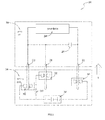
FIG. 3 is a block diagram of the electrical combination. -
FIG. 4 is a block diagram of another example of the electrical combination. -
FIG. 5 is a schematic view of a tool connector. -
FIG. 6 is a schematic view of another example of the tool connector. - The drawings described herein are for illustrative purposes only of selected embodiments and not all possible implementations, and are not intended to limit the scope of the present disclosure. Corresponding reference numerals indicate corresponding parts throughout the several views of the drawings.
- The following description of the preferred embodiments is merely exemplary in nature and is in no way intended to limit the scope of the invention hereinafter claimed, its application, or uses.
- As shown in
FIG. 1 , anelectrical combination 100 includes apower tool 200 and abattery pack 300. - Referring to
FIGS. 2-3 , thepower tool 200 includes atool housing 20 and apower device 204. Thepower tool 200 further includes tool connectors 201,202, 203 for connecting with thebattery pack 300 so that thebattery pack 300 can supply power to thepower device 204 of thepower tool 200. Thepower device 204 may be a motor, an indicating light or other device which uses electric energy to realize a power tool function. When thebattery pack 300 is connected with thepower tool 200, the tool connectors pass through terminal interfaces of thebattery pack 300, extend into ahousing 30 of thebattery pack 300, and connect with the battery pack connectors in thehousing 30 of thebattery pack 300. - As shown in
FIG. 2 , thebattery pack 300 includes thehousing 30 and a battery accommodated in thehousing 30. Thehousing 30 is provided with several terminal interfaces. Oneterminal interface 301 can correspond to one battery pack connector or several battery pack connectors. - As shown in
FIG. 3 , thepower tool 200 includes thefirst tool connector 201, thesecond tool connector 202, thethird tool connector 203, thepower device 204, and acapacitor 205. - The
first tool connector 201, thesecond tool connector 202, and thethird tool connector 203 are at least partially exposed out of thepower tool 200. - The
second tool connector 202 and thethird tool connector 203 are used to supply electric energy to thepower device 204. In order to realize a filter and to adjust the voltage, thecapacitor 205 is connected between thesecond tool connector 202 and thethird tool connector 203. If thesecond tool connector 202 and thethird tool connector 203 respectively contacts a positive electrode and a negative electrode of a power source simultaneously, a large current passes though thesecond tool connector 202 and thethird tool connector 203 instantly, and an electric spark may be generated so as to damage the tool connectors. - In order to solve the problem mentioned above, the
first tool connector 201 is arranged to connect with thesecond tool connector 202, that is to say both thefirst tool connector 201 and thesecond tool connector 202 connect with the same terminal of thecapacitor 205. For thecapacitor 205, thefirst tool connector 201 and thesecond tool connector 202 perform the same function. - The
battery pack 300 includes a firstbattery pack connector 301, a secondbattery pack connector 302, a thirdbattery pack connector 303, and abattery 304, which are arranged in thehousing 30 of thebattery pack 300. Thebattery pack 300 is provided with three terminal interfaces corresponding with the firstbattery pack connector 301, the secondbattery pack connector 302, and the thirdbattery pack connector 303, respectively. The first, second and thirdbattery pack connector third tool connector - The
first tool connector 201, thesecond tool connector 202, and thethird tool connector 203 are configured with a structure which facilitates insertion into the terminal interfaces of thebattery pack 300. In order to contact steadily with the first, second, and third tool connector 201,202, 203, the firstbattery pack connector 301, the secondbattery pack connector 302, and the thirdbattery pack connector 303 are configured with a clamping structure which is able to clamp the structure. - The first
battery pack connector 301, the secondbattery pack connector 302 and the thirdbattery pack connector 303 respectively include a first connection portion, a second connection portion, and a third connection portion which are used to contact with thefirst tool connector 201, thesecond tool connector 202, and thethird tool connector 203 inserted into thebattery pack 300. - As shown in
FIG. 3 , a negative electrode of thebattery 304 is connected with the thirdbattery pack connector 303, a positive electrode of thebattery 304 is connected with the firstbattery pack connector 301 and the secondbattery pack connector 302. Aresistor 305 is arranged between the positive electrode of thebattery 304 and the firstbattery pack connector 301, which can limit the current flowing therethrough. Theresistor 305 has a large resistance, so the resistance between the firstbattery pack connector 301 and the positive electrode of thebattery 304 is greater than the resistance between the secondbattery pack connector 302 and the negative electrode of thebattery 304. - The first, second, and third tool connector 201,202, 203 and the first, second and third
battery pack connector first tool connector 201 contacts with the firstbattery pack connector 301 before thesecond tool connector 202 contacts with secondbattery pack connector 302 when thebattery pack 300 is connected with thepower tool 200 along the direction B. That is, firstly, thefirst tool connector 201 contacts and connects with the firstbattery pack connector 301, and then thesecond tool connector 202 contacts and connects with the secondbattery pack connector 302. For the connection of thethird tool connector 203 and the thirdbattery pack connector 303 and the connection of thefirst tool connector 201 and the firstbattery pack connector 301, there is no predetermined sequence. But the connection of thethird tool connector 203 and the thirdbattery pack connector 303 is desired to be in advance of the connection of thesecond tool connector 202 and the secondbattery pack connector 302. - With this connection sequence, firstly, the
capacitor 205 is connected with the negative and positive electrodes of thebattery 304 through the connection of thethird tool connector 203 and the thirdbattery pack connector 303 and the connection of thefirst tool connector 201 and the firstbattery pack connector 301. The current in the circuit is limited because of theresistor 305. When thethird tool connector 203 is connected with the thirdbattery pack connector 303 and thesecond tool connector 202 is connected with the secondbattery pack connector 302, an electric spark should not be generated. Then, thesecond tool connector 202 is contacted and connected with the secondbattery pack connector 302, although the large current passes through the circuit constructed by the connection of thesecond tool connector 202 and the secondbattery pack connector 302, the electrical potential is decreased because thecapacitor 205 has been charged, so the possibility of generating an electric spark is reduced. While, because the resistance of the circuit constructed by the connection of thesecond tool connector 202 and the secondbattery pack connector 302 is less than the resistance of the circuit constructed by the connection of thefirst tool connector 201 and the firstbattery pack connector 301, the circuit of theresistor 305 is opened. Thepower device 204 can get electric energy from thebattery pack 300 through thesecond tool connector 202 and thethird tool connector 203. - As shown in
FIG. 3 , in order to realize the connection sequence, specifically, the first, second andthird tool connector battery pack connector battery pack connector battery pack connector 302 is located at a further position relative to the tool connectors so as to realize the connection sequence. Otherwise, the positive electrode and the negative electrode of thebattery 304 can be connected reversely to eliminate the electric spark. - As shown in
FIG. 5 , in another example, afirst tool connector 401 includes ametal portion 401 a and aninsulation portion 401b. Themetal portion 401a contacts with the firstbattery pack connector 301 firstly, and theinsulation portion 401b contacts with the firstbattery pack connector 301 when thesecond tool connector 202 is connected with secondbattery pack connector 302. Thus, after thesecond tool connector 202 is connected with the secondbattery pack connector 302, thefirst tool connector 401 is electrically disconnected with the firstbattery pack connector 301. - In the examples above, the
first tool connector 201 and thesecond tool connector 202 can be integrated as a whole, the two tool connectors are two portions of the whole, which have different locations and insulate with respect to each other, and the two tool connectors correspond with the different terminal interfaces, respectively. Likewsie, a whole including a pre-connection portion and a final connection portion which are insulated with each other can be used to perform the function of thefirst tool connector 201 and thesecond tool connector 202. - As shown in
FIG. 3 , the thirdbattery pack connector 303 is connected with one electrode of thebattery 304, the firstbattery pack connector 301 and the secondbattery pack connector 302 are connected with another electrode of thebattery 304, thefirst tool connector 201 is connected to one terminal of thecapacitor 205 of thepower tool 200, thesecond tool connector 202 is connected to one terminal of thecapacitor 205 of thepower tool 200, thethird tool connector 203 is connected with another terminal of thecapacitor 205. - A method for preventing the
battery pack connector 302 and thetool connector 202 of theelectrical combination 100 from generating electric spark is provided below. - The method may include a setting method for a manufacturer and a operating method for a user.
- The setting method may include providing a first
battery pack connector 301 which is connected to the secondbattery pack connector 302 and is configured to connect with thefirst tool connector 201 before thesecond tool connector 202 is connected to the secondbattery pack connector 302 andresistor 305 between the firstbattery pack connector 301 and the secondbattery pack connector 302. - The operating method may include connecting the first
battery pack connector 301 of thebattery pack 300 with thefirst tool connector 201 of thepower tool 200 firstly, and connecting the secondbattery pack connector 302 of thebattery pack 300 with thesecond tool connector 202 of thepower tool 200 secondly. - The operating method may further include connecting the third
battery pack connector 303 of thebattery pack 300 with thethird tool connector 202 of thepower tool 200. - As shown as
FIG. 3 and described above, it is helpful to avoid a large current shock and electric sparks between the battery pack and the power tool by using the discussed methods. - As shown in
FIG. 6 , further in another embodiment, afirst tool connector 501 is provided with a gap 501 c. When thesecond tool connector 202 is connected with the secondbattery pack connector 302, the firstbattery pack connector 301 corresponds with the gap 501c so as to electrically disconnect them. - As shown in
FIG. 4 , further in another embodiment, an electrical combination 100' includes a power tool 200' and a battery pack 300'. The power tool 200' includes a first tool connector 201', a second tool connector 202', a capacitor 203' and a power device 204'. The capacitor 203' and the power device 204' are connected between the first tool connector 201' and the second tool connector 202'. This is the arrangement of currently known power tool. The currently known power tool only includes two tool connectors respectively connected with the positive electrode and the negative electrode of the battery. Specifically, the two tool connectors are tool connection terminals. - The battery pack 300' includes a first battery pack connector 301', a second battery pack connector 302', a third battery pack connector 303' and a battery 304'. The third battery pack connector 303' is connected with the negative electrode of the battery 304' (or the positive electrode). The first battery pack connector 301' and the second battery pack connector 302' are connected with the positive electrode of the battery 304' (or the negative electrode). A resistor 305' is arranged between the first battery pack connector 301' and the positive electrode of the battery 304'. The first battery pack connector 301' and the second battery pack connector 302' use the same terminal interface, which can connect with the tool connector inserted into the terminal interface.
- The first battery pack connector 301' and the second battery pack connector 302' are so arranged that they contact with the first tool connector 201' successively when the battery pack 300' is connected with the power tool 200'.
- As shown in
FIG. 4 , when the first tool connector 201' passes through the terminal interface and inserts into the battery pack 300', it contacts with the first connection portion of the first battery pack connector 301', the large current cannot be generated because of the resistor 305'. When the first tool connector 201' further inserts, it contacts with the second connection portion of the second battery pack connector 302', and the connection circuit of the first battery pack connector 301' is short, so the battery 304' supplies electric energy to the power tool 200' at a normal discharging current. - The first tool connector 201' can be configured to have the structure as shown in
FIG. 5 and 6 so as to open the circuit of the first battery pack connector 301'. - Otherwise, the first battery pack connector 301' and the second battery pack connector 302' can be configured as a connection module for connecting with the tool connector, and the third battery pack connector 303' can be configured as another connection module. The two connection modules respectively correspond with different terminal interfaces and respectively connect with different tool connectors. It is noted that, the first battery pack connector 301' and the second battery pack connector 302' can be integrated as a whole, which have different locations in the connection direction B and insulate with respect to each other. Likewise, a whole including a pre-connection portion and a final connection portion which are insulated with respect to each other can be used to realize the function of the first and the second battery pack connector 301' , 302'.
- As shown in
FIG. 4 , the third battery pack connector 303' is connected with one electrode of the battery 304', the first battery pack connector 301' and the second battery pack connector 302' are connected with another electrode of the battery 304'; the first tool connector 201' is connected to one terminal of the capacitor 203' of the power tool 200', and the third tool connector 202' is connected with another terminal of the capacitor 203'. - A method for preventing the battery pack connector 302' and the tool connector 201' of the electrical combination 100' from generating electric spark is provided below.
- The method may include a setting method for a manufacturer and a operating method for a user.
- The setting method may include providing a first battery pack connector 301' which is connected to the second battery pack connector 302' and is configured to connect with the tool connector 201' before the tool connector 201' is connected to the second battery pack connector 302' and a resistor 305' between the first battery pack connector 301' and second battery pack connector 302'.
- The operating method may include connecting the first battery pack connector 301' of the battery pack 300' with the first tool connector 201' of the power tool 200' firstly, and connecting the second battery pack connector 302' of the battery pack 300' with the first tool connector 201' of the power tool 200' secondly.
- The operating method may further include connecting the third battery pack connector 303' of the battery pack 300' with the third tool connector 202' of the power tool 200'.
- As shown as
FIG. 4 and description above, It's helpful to avoid a large current shock and electric sparks between the battery pack and the power tool by using the methods described above. - The above illustrates and describes basic principles, main features and advantages of the present invention. Those skilled in the art should appreciate that the above embodiments do not limit the present invention in any form. Technical solutions obtained by equivalent substitution or equivalent variations all fall within the scope of the present invention.
Claims (7)
- An electrical combination, comprising:a power tool comprising:a power device configured to use electric energy to realize a power tool function;a capacitor connected with the power device;a first tool connector connected with a terminal of the capacitor;a second tool connector connected with the terminal of the capacitor; anda third tool connector connected with another terminal of the capacitor; anda battery pack comprising:wherein the first battery pack connector and the second battery pack connector are connected with one of the positive electrode or the negative electrode of the battery.a battery comprising a positive electrode and a negative electrode;a first battery pack connector for connecting with the first tool connector;a second battery pack connector for connecting with the second tool connector after the first battery pack connector connects with the first tool connector; anda resistor connected between the battery and the first battery pack connector for limiting the current flowing into or from the battery through the first battery pack connector;
- The electrical combination as recited in claim 1, wherein the battery pack comprises a third battery pack connector for connecting with the third tool connector, which is connected with an other one of the negative electrode or the positive electrode of the battery.
- An electrical combination, comprising:a power tool comprising:a power device configured to use electric energy to realize a power tool function;a capacitor connected with the power device;a first tool connector connected with a terminal of the capacitor; anda third tool connector connected with another terminal of the capacitor; anda battery pack comprising:a battery comprising a positive electrode and a negative electrode;a first battery pack connector for connecting with the first tool connector;a second battery pack connector for connecting with the first tool connector after the first battery pack connector connects with the first tool connector; anda resistor connected between the battery and the first battery pack connector and configured to limit the current that passes through the first battery pack connector;wherein the first battery pack connector and the second battery pack connector are connected with one of the positive electrode or the negative electrode of the battery.
- The electrical combination as recited in claim 3, wherein the battery pack comprises a third battery pack connector for connecting with the third tool connector, which is connected with an other one of the negative electrode or the positive electrode of the battery.
- The electrical combination as recited in claim 3, wherein the power device includes a motor.
- A battery pack configured for use with a power tool having a tool connector, comprising:a battery comprising a positive electrode and a negative electrode;a first battery pack connector configured to connect with the tool connector of the power tool;a second battery pack connector configured to connect with the same tool connector after the first battery pack connector connects with the power tool; anda resistor connected between the battery and the first battery pack connector and configured to limit the current flowing into or from the battery through the first battery pack connector;wherein the first battery pack connector and the second battery pack connector are connected with one of the positive electrode or the negative electrode of the battery.
- The battery pack as recited claim 6, further comprising a third battery pack connector for connecting with the tool connector, which is connected with an other one of the negative electrode or the positive electrode of the battery.
Applications Claiming Priority (1)
| Application Number | Priority Date | Filing Date | Title |
|---|---|---|---|
| CN201510471534.7A CN106450071B (en) | 2015-08-04 | 2015-08-04 | Battery pack and its with the combination of electric tool and the method for connecting them |
Publications (2)
| Publication Number | Publication Date |
|---|---|
| EP3138663A1 true EP3138663A1 (en) | 2017-03-08 |
| EP3138663B1 EP3138663B1 (en) | 2020-01-08 |
Family
ID=56800133
Family Applications (1)
| Application Number | Title | Priority Date | Filing Date |
|---|---|---|---|
| EP16180953.8A Active EP3138663B1 (en) | 2015-08-04 | 2016-07-25 | Battery pack and electrical combination |
Country Status (4)
| Country | Link |
|---|---|
| US (2) | US10476067B2 (en) |
| EP (1) | EP3138663B1 (en) |
| CN (1) | CN106450071B (en) |
| AU (1) | AU2016101351A4 (en) |
Families Citing this family (6)
| Publication number | Priority date | Publication date | Assignee | Title |
|---|---|---|---|---|
| EP3675200B1 (en) * | 2017-08-25 | 2023-07-05 | Positec Power Tools (Suzhou) Co., Ltd | Electric tool and method for supplying power to electric tool |
| CN112204843A (en) | 2018-05-30 | 2021-01-08 | 米沃奇电动工具公司 | fast charging battery pack |
| KR20250039180A (en) | 2023-09-13 | 2025-03-20 | 삼성에스디아이 주식회사 | Connecting device |
| USD1123821S1 (en) * | 2024-06-13 | 2026-04-28 | Jiangsu Dongcheng Tools Technology Co., Ltd. | Battery pack |
| USD1117001S1 (en) * | 2025-04-14 | 2026-03-10 | Lianpeng Chen | Battery pack |
| USD1117000S1 (en) * | 2025-04-14 | 2026-03-10 | Lianpeng Chen | Battery pack |
Citations (8)
| Publication number | Priority date | Publication date | Assignee | Title |
|---|---|---|---|---|
| DE10040893A1 (en) * | 1999-08-19 | 2001-08-02 | Makita Corp | Terminal structure for battery pack, includes alterable number of elastic board formed on receptacle in entry direction of male terminal, for fitting male terminal |
| US20040017177A1 (en) * | 2002-07-25 | 2004-01-29 | Santana George L. | Battery, battery charger, electrical system and method of charging a battery |
| US20060091858A1 (en) * | 2002-11-22 | 2006-05-04 | Johnson Todd W | Method and system for battery protection |
| EP1927438A1 (en) * | 2006-11-28 | 2008-06-04 | Black & Decker, Inc. | Battery pack lockout arrangement for cordless power tools |
| US20110250780A1 (en) * | 2010-04-13 | 2011-10-13 | Makita Corporation | Connecting structure of terminals |
| US20120274245A1 (en) * | 2010-01-22 | 2012-11-01 | Hitachi Koki Co. Ltd. | Power Tool and Battery Pack |
| EP2554335A1 (en) * | 2010-03-26 | 2013-02-06 | Panasonic Corporation | Electric tool |
| EP2713474A2 (en) * | 2012-09-26 | 2014-04-02 | Panasonic Corporation | Driving control circuit and power tool |
Family Cites Families (7)
| Publication number | Priority date | Publication date | Assignee | Title |
|---|---|---|---|---|
| JPH09271144A (en) * | 1996-01-29 | 1997-10-14 | Sony Corp | Power supply identification method, dry battery pack, electronic device |
| JP4820061B2 (en) * | 2004-03-05 | 2011-11-24 | 日立工機株式会社 | Battery tools |
| US9136716B2 (en) * | 2007-10-15 | 2015-09-15 | Black & Decker Inc. | Bottom based balancing in lithium ion system |
| US8582268B2 (en) * | 2008-05-30 | 2013-11-12 | Panasonic Corporation | Circuit for preventing inrush current |
| CN102761114B (en) * | 2012-07-18 | 2015-01-28 | 海能达通信股份有限公司 | Surge current suppression circuit |
| CN103730784B (en) * | 2014-01-19 | 2016-12-07 | 国网山东省电力公司日照供电公司 | A kind of socket eliminating electric spark |
| US10348110B2 (en) * | 2015-02-13 | 2019-07-09 | Makita Corporation | Battery pack |
-
2015
- 2015-08-04 CN CN201510471534.7A patent/CN106450071B/en active Active
-
2016
- 2016-07-25 EP EP16180953.8A patent/EP3138663B1/en active Active
- 2016-07-28 US US15/221,715 patent/US10476067B2/en active Active
- 2016-08-02 AU AU2016101351A patent/AU2016101351A4/en not_active Expired
-
2019
- 2019-09-06 US US16/562,908 patent/US10964990B2/en active Active
Patent Citations (8)
| Publication number | Priority date | Publication date | Assignee | Title |
|---|---|---|---|---|
| DE10040893A1 (en) * | 1999-08-19 | 2001-08-02 | Makita Corp | Terminal structure for battery pack, includes alterable number of elastic board formed on receptacle in entry direction of male terminal, for fitting male terminal |
| US20040017177A1 (en) * | 2002-07-25 | 2004-01-29 | Santana George L. | Battery, battery charger, electrical system and method of charging a battery |
| US20060091858A1 (en) * | 2002-11-22 | 2006-05-04 | Johnson Todd W | Method and system for battery protection |
| EP1927438A1 (en) * | 2006-11-28 | 2008-06-04 | Black & Decker, Inc. | Battery pack lockout arrangement for cordless power tools |
| US20120274245A1 (en) * | 2010-01-22 | 2012-11-01 | Hitachi Koki Co. Ltd. | Power Tool and Battery Pack |
| EP2554335A1 (en) * | 2010-03-26 | 2013-02-06 | Panasonic Corporation | Electric tool |
| US20110250780A1 (en) * | 2010-04-13 | 2011-10-13 | Makita Corporation | Connecting structure of terminals |
| EP2713474A2 (en) * | 2012-09-26 | 2014-04-02 | Panasonic Corporation | Driving control circuit and power tool |
Also Published As
| Publication number | Publication date |
|---|---|
| CN106450071B (en) | 2019-08-06 |
| AU2016101351A4 (en) | 2016-09-15 |
| US20190393475A1 (en) | 2019-12-26 |
| US10476067B2 (en) | 2019-11-12 |
| US20170040587A1 (en) | 2017-02-09 |
| EP3138663B1 (en) | 2020-01-08 |
| CN106450071A (en) | 2017-02-22 |
| US10964990B2 (en) | 2021-03-30 |
Similar Documents
| Publication | Publication Date | Title |
|---|---|---|
| US10964990B2 (en) | Battery pack and electrical combination | |
| EP3660949B1 (en) | Power tool system and battery pack thereof | |
| US10559804B2 (en) | Battery pack | |
| EP2930771B1 (en) | Rechargeable battery | |
| JP2009231138A (en) | Battery pack | |
| EP3123539A1 (en) | Connector for connecting cellular electrical elements and method for installing such a connector on a battery unit | |
| CN105723232A (en) | Detachable voltage sensing module and battery device having same | |
| KR20150057732A (en) | Protection apparutus for rechargeable battery | |
| US20170077723A1 (en) | Battery system with overcharge and/or exhaustive-discharge protection | |
| EP3703178B1 (en) | Battery module | |
| KR20160139807A (en) | Battery pack | |
| CN103682504B (en) | Battery and motor vehicle | |
| CN209169322U (en) | Cover plate assembly for cell and cell having the same | |
| CN115986860A (en) | Wireless and Conductive Energy Transfer Units | |
| CN1319914A (en) | Accumulator with electronic safety protection circuit | |
| GB2544363A (en) | Prismatic accumulator cell and accumulator pack | |
| CN121192376B (en) | Electric connector, battery pack and energy storage system | |
| CN105428856B (en) | A kind of connector | |
| CN214069021U (en) | Electrical connection device | |
| US20260091694A1 (en) | Method and system for charging an electrically operated vehicle on a charging device using a charging adapter | |
| CN102881854B (en) | Battery with multiple secondary battery units | |
| CN1934730B (en) | device with battery | |
| US9166256B2 (en) | Rechargeable battery | |
| KR20200137224A (en) | Battery module, battery rack and energy storage system comprising the same | |
| JP2021048754A (en) | Charging inlet |
Legal Events
| Date | Code | Title | Description |
|---|---|---|---|
| PUAI | Public reference made under article 153(3) epc to a published international application that has entered the european phase |
Free format text: ORIGINAL CODE: 0009012 |
|
| STAA | Information on the status of an ep patent application or granted ep patent |
Free format text: STATUS: THE APPLICATION HAS BEEN PUBLISHED |
|
| AK | Designated contracting states |
Kind code of ref document: A1 Designated state(s): AL AT BE BG CH CY CZ DE DK EE ES FI FR GB GR HR HU IE IS IT LI LT LU LV MC MK MT NL NO PL PT RO RS SE SI SK SM TR |
|
| AX | Request for extension of the european patent |
Extension state: BA ME |
|
| STAA | Information on the status of an ep patent application or granted ep patent |
Free format text: STATUS: REQUEST FOR EXAMINATION WAS MADE |
|
| 17P | Request for examination filed |
Effective date: 20170824 |
|
| RBV | Designated contracting states (corrected) |
Designated state(s): AL AT BE BG CH CY CZ DE DK EE ES FI FR GB GR HR HU IE IS IT LI LT LU LV MC MK MT NL NO PL PT RO RS SE SI SK SM TR |
|
| STAA | Information on the status of an ep patent application or granted ep patent |
Free format text: STATUS: EXAMINATION IS IN PROGRESS |
|
| 17Q | First examination report despatched |
Effective date: 20190529 |
|
| GRAP | Despatch of communication of intention to grant a patent |
Free format text: ORIGINAL CODE: EPIDOSNIGR1 |
|
| STAA | Information on the status of an ep patent application or granted ep patent |
Free format text: STATUS: GRANT OF PATENT IS INTENDED |
|
| INTG | Intention to grant announced |
Effective date: 20191024 |
|
| GRAS | Grant fee paid |
Free format text: ORIGINAL CODE: EPIDOSNIGR3 |
|
| GRAA | (expected) grant |
Free format text: ORIGINAL CODE: 0009210 |
|
| STAA | Information on the status of an ep patent application or granted ep patent |
Free format text: STATUS: THE PATENT HAS BEEN GRANTED |
|
| AK | Designated contracting states |
Kind code of ref document: B1 Designated state(s): AL AT BE BG CH CY CZ DE DK EE ES FI FR GB GR HR HU IE IS IT LI LT LU LV MC MK MT NL NO PL PT RO RS SE SI SK SM TR |
|
| REG | Reference to a national code |
Ref country code: GB Ref legal event code: FG4D |
|
| REG | Reference to a national code |
Ref country code: CH Ref legal event code: EP |
|
| REG | Reference to a national code |
Ref country code: DE Ref legal event code: R096 Ref document number: 602016027691 Country of ref document: DE |
|
| REG | Reference to a national code |
Ref country code: IE Ref legal event code: FG4D |
|
| REG | Reference to a national code |
Ref country code: AT Ref legal event code: REF Ref document number: 1222116 Country of ref document: AT Kind code of ref document: T Effective date: 20200215 |
|
| REG | Reference to a national code |
Ref country code: NL Ref legal event code: MP Effective date: 20200108 |
|
| REG | Reference to a national code |
Ref country code: LT Ref legal event code: MG4D |
|
| PG25 | Lapsed in a contracting state [announced via postgrant information from national office to epo] |
Ref country code: PT Free format text: LAPSE BECAUSE OF FAILURE TO SUBMIT A TRANSLATION OF THE DESCRIPTION OR TO PAY THE FEE WITHIN THE PRESCRIBED TIME-LIMIT Effective date: 20200531 Ref country code: FI Free format text: LAPSE BECAUSE OF FAILURE TO SUBMIT A TRANSLATION OF THE DESCRIPTION OR TO PAY THE FEE WITHIN THE PRESCRIBED TIME-LIMIT Effective date: 20200108 Ref country code: NO Free format text: LAPSE BECAUSE OF FAILURE TO SUBMIT A TRANSLATION OF THE DESCRIPTION OR TO PAY THE FEE WITHIN THE PRESCRIBED TIME-LIMIT Effective date: 20200408 Ref country code: LT Free format text: LAPSE BECAUSE OF FAILURE TO SUBMIT A TRANSLATION OF THE DESCRIPTION OR TO PAY THE FEE WITHIN THE PRESCRIBED TIME-LIMIT Effective date: 20200108 Ref country code: RS Free format text: LAPSE BECAUSE OF FAILURE TO SUBMIT A TRANSLATION OF THE DESCRIPTION OR TO PAY THE FEE WITHIN THE PRESCRIBED TIME-LIMIT Effective date: 20200108 Ref country code: NL Free format text: LAPSE BECAUSE OF FAILURE TO SUBMIT A TRANSLATION OF THE DESCRIPTION OR TO PAY THE FEE WITHIN THE PRESCRIBED TIME-LIMIT Effective date: 20200108 |
|
| PG25 | Lapsed in a contracting state [announced via postgrant information from national office to epo] |
Ref country code: BG Free format text: LAPSE BECAUSE OF FAILURE TO SUBMIT A TRANSLATION OF THE DESCRIPTION OR TO PAY THE FEE WITHIN THE PRESCRIBED TIME-LIMIT Effective date: 20200408 Ref country code: GR Free format text: LAPSE BECAUSE OF FAILURE TO SUBMIT A TRANSLATION OF THE DESCRIPTION OR TO PAY THE FEE WITHIN THE PRESCRIBED TIME-LIMIT Effective date: 20200409 Ref country code: IS Free format text: LAPSE BECAUSE OF FAILURE TO SUBMIT A TRANSLATION OF THE DESCRIPTION OR TO PAY THE FEE WITHIN THE PRESCRIBED TIME-LIMIT Effective date: 20200508 Ref country code: SE Free format text: LAPSE BECAUSE OF FAILURE TO SUBMIT A TRANSLATION OF THE DESCRIPTION OR TO PAY THE FEE WITHIN THE PRESCRIBED TIME-LIMIT Effective date: 20200108 Ref country code: LV Free format text: LAPSE BECAUSE OF FAILURE TO SUBMIT A TRANSLATION OF THE DESCRIPTION OR TO PAY THE FEE WITHIN THE PRESCRIBED TIME-LIMIT Effective date: 20200108 Ref country code: HR Free format text: LAPSE BECAUSE OF FAILURE TO SUBMIT A TRANSLATION OF THE DESCRIPTION OR TO PAY THE FEE WITHIN THE PRESCRIBED TIME-LIMIT Effective date: 20200108 |
|
| REG | Reference to a national code |
Ref country code: DE Ref legal event code: R097 Ref document number: 602016027691 Country of ref document: DE |
|
| PG25 | Lapsed in a contracting state [announced via postgrant information from national office to epo] |
Ref country code: ES Free format text: LAPSE BECAUSE OF FAILURE TO SUBMIT A TRANSLATION OF THE DESCRIPTION OR TO PAY THE FEE WITHIN THE PRESCRIBED TIME-LIMIT Effective date: 20200108 Ref country code: CZ Free format text: LAPSE BECAUSE OF FAILURE TO SUBMIT A TRANSLATION OF THE DESCRIPTION OR TO PAY THE FEE WITHIN THE PRESCRIBED TIME-LIMIT Effective date: 20200108 Ref country code: SK Free format text: LAPSE BECAUSE OF FAILURE TO SUBMIT A TRANSLATION OF THE DESCRIPTION OR TO PAY THE FEE WITHIN THE PRESCRIBED TIME-LIMIT Effective date: 20200108 Ref country code: RO Free format text: LAPSE BECAUSE OF FAILURE TO SUBMIT A TRANSLATION OF THE DESCRIPTION OR TO PAY THE FEE WITHIN THE PRESCRIBED TIME-LIMIT Effective date: 20200108 Ref country code: SM Free format text: LAPSE BECAUSE OF FAILURE TO SUBMIT A TRANSLATION OF THE DESCRIPTION OR TO PAY THE FEE WITHIN THE PRESCRIBED TIME-LIMIT Effective date: 20200108 Ref country code: EE Free format text: LAPSE BECAUSE OF FAILURE TO SUBMIT A TRANSLATION OF THE DESCRIPTION OR TO PAY THE FEE WITHIN THE PRESCRIBED TIME-LIMIT Effective date: 20200108 Ref country code: DK Free format text: LAPSE BECAUSE OF FAILURE TO SUBMIT A TRANSLATION OF THE DESCRIPTION OR TO PAY THE FEE WITHIN THE PRESCRIBED TIME-LIMIT Effective date: 20200108 |
|
| PLBE | No opposition filed within time limit |
Free format text: ORIGINAL CODE: 0009261 |
|
| STAA | Information on the status of an ep patent application or granted ep patent |
Free format text: STATUS: NO OPPOSITION FILED WITHIN TIME LIMIT |
|
| REG | Reference to a national code |
Ref country code: AT Ref legal event code: MK05 Ref document number: 1222116 Country of ref document: AT Kind code of ref document: T Effective date: 20200108 |
|
| 26N | No opposition filed |
Effective date: 20201009 |
|
| PG25 | Lapsed in a contracting state [announced via postgrant information from national office to epo] |
Ref country code: IT Free format text: LAPSE BECAUSE OF FAILURE TO SUBMIT A TRANSLATION OF THE DESCRIPTION OR TO PAY THE FEE WITHIN THE PRESCRIBED TIME-LIMIT Effective date: 20200108 Ref country code: AT Free format text: LAPSE BECAUSE OF FAILURE TO SUBMIT A TRANSLATION OF THE DESCRIPTION OR TO PAY THE FEE WITHIN THE PRESCRIBED TIME-LIMIT Effective date: 20200108 |
|
| PG25 | Lapsed in a contracting state [announced via postgrant information from national office to epo] |
Ref country code: SI Free format text: LAPSE BECAUSE OF FAILURE TO SUBMIT A TRANSLATION OF THE DESCRIPTION OR TO PAY THE FEE WITHIN THE PRESCRIBED TIME-LIMIT Effective date: 20200108 Ref country code: PL Free format text: LAPSE BECAUSE OF FAILURE TO SUBMIT A TRANSLATION OF THE DESCRIPTION OR TO PAY THE FEE WITHIN THE PRESCRIBED TIME-LIMIT Effective date: 20200108 Ref country code: MC Free format text: LAPSE BECAUSE OF FAILURE TO SUBMIT A TRANSLATION OF THE DESCRIPTION OR TO PAY THE FEE WITHIN THE PRESCRIBED TIME-LIMIT Effective date: 20200108 |
|
| REG | Reference to a national code |
Ref country code: CH Ref legal event code: PL |
|
| REG | Reference to a national code |
Ref country code: BE Ref legal event code: MM Effective date: 20200731 |
|
| PG25 | Lapsed in a contracting state [announced via postgrant information from national office to epo] |
Ref country code: LU Free format text: LAPSE BECAUSE OF NON-PAYMENT OF DUE FEES Effective date: 20200725 Ref country code: LI Free format text: LAPSE BECAUSE OF NON-PAYMENT OF DUE FEES Effective date: 20200731 Ref country code: CH Free format text: LAPSE BECAUSE OF NON-PAYMENT OF DUE FEES Effective date: 20200731 |
|
| PG25 | Lapsed in a contracting state [announced via postgrant information from national office to epo] |
Ref country code: BE Free format text: LAPSE BECAUSE OF NON-PAYMENT OF DUE FEES Effective date: 20200731 |
|
| PG25 | Lapsed in a contracting state [announced via postgrant information from national office to epo] |
Ref country code: IE Free format text: LAPSE BECAUSE OF NON-PAYMENT OF DUE FEES Effective date: 20200725 |
|
| PG25 | Lapsed in a contracting state [announced via postgrant information from national office to epo] |
Ref country code: TR Free format text: LAPSE BECAUSE OF FAILURE TO SUBMIT A TRANSLATION OF THE DESCRIPTION OR TO PAY THE FEE WITHIN THE PRESCRIBED TIME-LIMIT Effective date: 20200108 Ref country code: MT Free format text: LAPSE BECAUSE OF FAILURE TO SUBMIT A TRANSLATION OF THE DESCRIPTION OR TO PAY THE FEE WITHIN THE PRESCRIBED TIME-LIMIT Effective date: 20200108 Ref country code: CY Free format text: LAPSE BECAUSE OF FAILURE TO SUBMIT A TRANSLATION OF THE DESCRIPTION OR TO PAY THE FEE WITHIN THE PRESCRIBED TIME-LIMIT Effective date: 20200108 |
|
| PG25 | Lapsed in a contracting state [announced via postgrant information from national office to epo] |
Ref country code: MK Free format text: LAPSE BECAUSE OF FAILURE TO SUBMIT A TRANSLATION OF THE DESCRIPTION OR TO PAY THE FEE WITHIN THE PRESCRIBED TIME-LIMIT Effective date: 20200108 Ref country code: AL Free format text: LAPSE BECAUSE OF FAILURE TO SUBMIT A TRANSLATION OF THE DESCRIPTION OR TO PAY THE FEE WITHIN THE PRESCRIBED TIME-LIMIT Effective date: 20200108 |
|
| REG | Reference to a national code |
Ref country code: DE Ref legal event code: R082 Ref document number: 602016027691 Country of ref document: DE Representative=s name: SUN, YIMING, M.SC. DIPL. SC. POL. UNIV., DE |
|
| PGFP | Annual fee paid to national office [announced via postgrant information from national office to epo] |
Ref country code: GB Payment date: 20250605 Year of fee payment: 10 |
|
| PGFP | Annual fee paid to national office [announced via postgrant information from national office to epo] |
Ref country code: FR Payment date: 20250610 Year of fee payment: 10 |
|
| PGFP | Annual fee paid to national office [announced via postgrant information from national office to epo] |
Ref country code: DE Payment date: 20250528 Year of fee payment: 10 |