EP3138629A1 - Biomass carrier element for biological treatment systems - Google Patents
Biomass carrier element for biological treatment systems Download PDFInfo
- Publication number
- EP3138629A1 EP3138629A1 EP15785805.1A EP15785805A EP3138629A1 EP 3138629 A1 EP3138629 A1 EP 3138629A1 EP 15785805 A EP15785805 A EP 15785805A EP 3138629 A1 EP3138629 A1 EP 3138629A1
- Authority
- EP
- European Patent Office
- Prior art keywords
- tubular body
- carrier element
- opening
- blades
- biomass
- Prior art date
- Legal status (The legal status is an assumption and is not a legal conclusion. Google has not performed a legal analysis and makes no representation as to the accuracy of the status listed.)
- Granted
Links
Images

Classifications
-
- C—CHEMISTRY; METALLURGY
- C02—TREATMENT OF WATER, WASTE WATER, SEWAGE, OR SLUDGE
- C02F—TREATMENT OF WATER, WASTE WATER, SEWAGE, OR SLUDGE
- C02F3/00—Biological treatment of water, waste water, or sewage
- C02F3/02—Aerobic processes
- C02F3/10—Packings; Fillings; Grids
- C02F3/109—Characterized by the shape
-
- B—PERFORMING OPERATIONS; TRANSPORTING
- B01—PHYSICAL OR CHEMICAL PROCESSES OR APPARATUS IN GENERAL
- B01J—CHEMICAL OR PHYSICAL PROCESSES, e.g. CATALYSIS OR COLLOID CHEMISTRY; THEIR RELEVANT APPARATUS
- B01J19/00—Chemical, physical or physico-chemical processes in general; Their relevant apparatus
- B01J19/30—Loose or shaped packing elements, e.g. Raschig rings or Berl saddles, for pouring into the apparatus for mass or heat transfer
-
- B—PERFORMING OPERATIONS; TRANSPORTING
- B01—PHYSICAL OR CHEMICAL PROCESSES OR APPARATUS IN GENERAL
- B01J—CHEMICAL OR PHYSICAL PROCESSES, e.g. CATALYSIS OR COLLOID CHEMISTRY; THEIR RELEVANT APPARATUS
- B01J2219/00—Chemical, physical or physico-chemical processes in general; Their relevant apparatus
- B01J2219/30—Details relating to random packing elements
- B01J2219/302—Basic shape of the elements
- B01J2219/30226—Cone or truncated cone
-
- B—PERFORMING OPERATIONS; TRANSPORTING
- B01—PHYSICAL OR CHEMICAL PROCESSES OR APPARATUS IN GENERAL
- B01J—CHEMICAL OR PHYSICAL PROCESSES, e.g. CATALYSIS OR COLLOID CHEMISTRY; THEIR RELEVANT APPARATUS
- B01J2219/00—Chemical, physical or physico-chemical processes in general; Their relevant apparatus
- B01J2219/30—Details relating to random packing elements
- B01J2219/304—Composition or microstructure of the elements
- B01J2219/30466—Plastics
-
- B—PERFORMING OPERATIONS; TRANSPORTING
- B01—PHYSICAL OR CHEMICAL PROCESSES OR APPARATUS IN GENERAL
- B01J—CHEMICAL OR PHYSICAL PROCESSES, e.g. CATALYSIS OR COLLOID CHEMISTRY; THEIR RELEVANT APPARATUS
- B01J2219/00—Chemical, physical or physico-chemical processes in general; Their relevant apparatus
- B01J2219/30—Details relating to random packing elements
- B01J2219/318—Manufacturing aspects
- B01J2219/3183—Molding
-
- C—CHEMISTRY; METALLURGY
- C02—TREATMENT OF WATER, WASTE WATER, SEWAGE, OR SLUDGE
- C02F—TREATMENT OF WATER, WASTE WATER, SEWAGE, OR SLUDGE
- C02F3/00—Biological treatment of water, waste water, or sewage
- C02F3/02—Aerobic processes
- C02F3/10—Packings; Fillings; Grids
- C02F3/105—Characterized by the chemical composition
- C02F3/106—Carbonaceous materials
-
- Y—GENERAL TAGGING OF NEW TECHNOLOGICAL DEVELOPMENTS; GENERAL TAGGING OF CROSS-SECTIONAL TECHNOLOGIES SPANNING OVER SEVERAL SECTIONS OF THE IPC; TECHNICAL SUBJECTS COVERED BY FORMER USPC CROSS-REFERENCE ART COLLECTIONS [XRACs] AND DIGESTS
- Y02—TECHNOLOGIES OR APPLICATIONS FOR MITIGATION OR ADAPTATION AGAINST CLIMATE CHANGE
- Y02W—CLIMATE CHANGE MITIGATION TECHNOLOGIES RELATED TO WASTEWATER TREATMENT OR WASTE MANAGEMENT
- Y02W10/00—Technologies for wastewater treatment
- Y02W10/10—Biological treatment of water, waste water, or sewage
Definitions
- the object of this invention is a carrier element for biomass generated in biological treatment processes of municipal and industrial wastewater, sludge treatment and gas cleaning, by means of aerobic or anaerobic systems called moving bed and fixed bed systems or upflow anaerobic systems.
- the wastewater and sludge treatment system by means of a moving bed system has been known for some years; however, the same is not true for the gas and air treatment system in general.
- This system consists of a specifically shaped plastic element that has cavities, inside of which bacteria colonies form, and these colonies degrade the organic matter contained in the wastewater.
- carriers plastic fill elements, commonly called “carriers”, must have some specific features such as rough, curved surfaces to facilitate the attachment of bacteria colonies to them; wide, open spaces that allow fluids to easily flow through them; and a small size with external contours that facilitate their movement through the fluid in the case of moving bed and upflow systems.
- Another objective of the invention is to define the non-stick means in that carrier element which prevent, or significantly reduce, the possibility that carrier elements stick together, forming groups that impede the circulation of fluids through its interior.
- the carrier element comprises: - a frustoconical tubular body provided with an opening of a smaller diameter and an opening of a greater diameter; - S-shaped radial walls defined inside the tubular body and converging at a central shaft; curved internal blades extending radially from the internal wall of the tubular body or from the central shaft and disposed, in a cantilevered manner, between the radial walls, leaving a free space to improve the circulation of fluids; and - a plurality of external blades that are the same height as the tubular body, which are perpendicular to the wall of said tubular body, and which are evenly distributed around same.
- the ends of the S-shaped radial walls extend out from diametrically opposite points of the tubular body, converging at the central shaft.
- the larger opening of the tubular body has a flat perimeter ring on its exterior that is perpendicular to the geometric axis of said tubular body.
- This perimeter ring has a small height and projects from the tubular body at a distance that is equal to the length of the exterior blades, helping prevent the carrying elements from sticking together.
- the internal blades are taller the closer they are to the central area of the tubular body, exceeding the height of the tubular body and protruding from the opposite openings of that tubular body; such that they make up non-stick means of the carrier elements by preventing them from entering and sticking to each other.
- the arrangement of the walls and the internal blades provide a greater surface area for the placement of the biomass, and by reducing the interior spaces, it channels the fluid currents in such a way that they do not drag the biomass colonies outwards.
- the external blades are arranged longitudinally throughout the tubular body and become thicker the closer they get to the perimeter ring that is located at the opening of a greater diameter of the tubular body.
- the aforementioned carrier element is made up of a heat-injected plastic material, which has walls with microcavities produced by microerosion to that carrier element's manufacturing matrix; and the purpose of those microcavities is to improve the attachment of the biomass colonies to the carrier element.
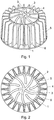
- the carrier element object of the invention comprises a frustoconical tubular body (1) provided with an upper opening of a smaller diameter and a lower opening of a greater diameter; and S-shaped radial walls (2) disposed inside the tubular body that converge at a central shaft (3).
- the carrier element comprises a plurality of external blades (5) which are the same height as the tubular body, are perpendicular to the wall of said tubular body, and are evenly distributed around the same.
- the larger opening of the tubular body has a flat perimeter ring (6) on its exterior that is perpendicular to the geometric axis of said tubular body (1).
- the radial walls (2) and the internal blades (4) are taller the closer they are to the central area of the tubular body (1), exceeding the height of the tubular body and protruding from the opposite openings of the same.
- the carrier element is made up of a heat-injected plastic material.
- Said plastic material can be made of, for example, either new or restored polypropylene or polyethylene.
- the filling element has a density of approximately 0.98 g/cm 3
- it has a density of approximately 1.02 g/cm 3 .
- the frustoconical tubular body (1) has a small opening with a diameter of 20 mm, a large opening with a diameter of 22 mm, and a height of 20 mm; and the height of the carrier element is 25 mm at its center point.
- the external blades (5) are 5 mm long and their height is the same as that of the tubular body (1). These external blades will facilitate the rotating movement of the carrier element.
- the carrier element can have a configuration similar to the one described previously, but with a size reduction of up to 40% of the same.
Abstract
Description
- The object of this invention is a carrier element for biomass generated in biological treatment processes of municipal and industrial wastewater, sludge treatment and gas cleaning, by means of aerobic or anaerobic systems called moving bed and fixed bed systems or upflow anaerobic systems.
- The wastewater and sludge treatment system by means of a moving bed system has been known for some years; however, the same is not true for the gas and air treatment system in general. This system consists of a specifically shaped plastic element that has cavities, inside of which bacteria colonies form, and these colonies degrade the organic matter contained in the wastewater.
- There are different models of plastic pieces on the market that are found in various shapes, sizes and materials and used successfully; it is worth noting the existence of utility model
ES 1064520 U - These plastic fill elements, commonly called "carriers", must have some specific features such as rough, curved surfaces to facilitate the attachment of bacteria colonies to them; wide, open spaces that allow fluids to easily flow through them; and a small size with external contours that facilitate their movement through the fluid in the case of moving bed and upflow systems.
- Therefore, the technical problem that is posed is the development of fill elements which provide improved features in order to increase their effectiveness and use in treatment systems.
- The biomass carrier element for biological treatment systems, especially applicable for the treatment of wastewater, sludge and gases by means of a fixed biomass process, has features that are improved and aimed at increasing its specific surface area with respect to the existing background.
- Another objective of the invention is to define the non-stick means in that carrier element which prevent, or significantly reduce, the possibility that carrier elements stick together, forming groups that impede the circulation of fluids through its interior.
- According to the invention, the carrier element comprises: - a frustoconical tubular body provided with an opening of a smaller diameter and an opening of a greater diameter; - S-shaped radial walls defined inside the tubular body and converging at a central shaft; curved internal blades extending radially from the internal wall of the tubular body or from the central shaft and disposed, in a cantilevered manner, between the radial walls, leaving a free space to improve the circulation of fluids; and - a plurality of external blades that are the same height as the tubular body, which are perpendicular to the wall of said tubular body, and which are evenly distributed around same.
- The purpose of these external blades is to facilitate the rotating movement of the carrier element during its use.
- The ends of the S-shaped radial walls extend out from diametrically opposite points of the tubular body, converging at the central shaft.
- The larger opening of the tubular body has a flat perimeter ring on its exterior that is perpendicular to the geometric axis of said tubular body. This perimeter ring has a small height and projects from the tubular body at a distance that is equal to the length of the exterior blades, helping prevent the carrying elements from sticking together.
- The internal blades are taller the closer they are to the central area of the tubular body, exceeding the height of the tubular body and protruding from the opposite openings of that tubular body; such that they make up non-stick means of the carrier elements by preventing them from entering and sticking to each other.
- The arrangement of the walls and the internal blades provide a greater surface area for the placement of the biomass, and by reducing the interior spaces, it channels the fluid currents in such a way that they do not drag the biomass colonies outwards.
- The external blades are arranged longitudinally throughout the tubular body and become thicker the closer they get to the perimeter ring that is located at the opening of a greater diameter of the tubular body.
- The aforementioned carrier element is made up of a heat-injected plastic material, which has walls with microcavities produced by microerosion to that carrier element's manufacturing matrix; and the purpose of those microcavities is to improve the attachment of the biomass colonies to the carrier element.
- As a complement to the description provided herein, and for the purpose of helping to make the characteristics of the invention more readily understandable, the present specification is accompanied by a set of drawings constituting an integral part of the same, which, by way of illustration and not limitation, represent the following:
-
Figure 1 shows an upper perspective view of the biomass carrier element for biological treatment systems, according to the invention. -
Figure 2 shows a front view of the biomass carrier element of the preceding figure. -
Figure 3 shows a lower perspective view of the biomass carrier element of the preceding figures. - As can be observed in the attached figures, the carrier element object of the invention comprises a frustoconical tubular body (1) provided with an upper opening of a smaller diameter and a lower opening of a greater diameter; and S-shaped radial walls (2) disposed inside the tubular body that converge at a central shaft (3).
- Inside the aforementioned tubular body (1) there are also curved internal blades (4) which in the example shown extend radially from the internal wall of the tubular body (1) and are disposed, in a cantilevered manner, between the radial walls, without reaching the central shaft (3).
- The carrier element comprises a plurality of external blades (5) which are the same height as the tubular body, are perpendicular to the wall of said tubular body, and are evenly distributed around the same.
- In the exemplary embodiment shown in the figures, the larger opening of the tubular body has a flat perimeter ring (6) on its exterior that is perpendicular to the geometric axis of said tubular body (1).
- The radial walls (2) and the internal blades (4) are taller the closer they are to the central area of the tubular body (1), exceeding the height of the tubular body and protruding from the opposite openings of the same.
- In this invention, the carrier element is made up of a heat-injected plastic material. Said plastic material can be made of, for example, either new or restored polypropylene or polyethylene. There is also the possibility that it may include an inert material that increases its weight and can be used in salt water and therefore, in fish farms in order to eliminate nitrates. In the first case, the filling element has a density of approximately 0.98 g/cm3, and in the second case, it has a density of approximately 1.02 g/cm3.
- In the example shown of the carrier element, the frustoconical tubular body (1) has a small opening with a diameter of 20 mm, a large opening with a diameter of 22 mm, and a height of 20 mm; and the height of the carrier element is 25 mm at its center point. The external blades (5) are 5 mm long and their height is the same as that of the tubular body (1). These external blades will facilitate the rotating movement of the carrier element. The carrier element can have a configuration similar to the one described previously, but with a size reduction of up to 40% of the same.
- Having sufficiently described the nature of the invention, in addition to an example of preferred embodiment, it is hereby stated for the relevant purposes that the materials, shape, size and layout of the described elements may be modified, provided that it does not imply altering the essential characteristics of the invention claimed below.
Claims (5)
- A biomass carrier element for biological treatment systems using the fixed biomass process, characterized in that it comprises: - a frustoconical tubular body (1) provided with an opening of a smaller diameter and an opening of a greater diameter; - S-shaped radial walls (2) defined inside the tubular body (1) and converging at a central shaft (3); curved internal blades (4) extending radially from the internal wall of the tubular body (1) or from the central shaft (3) and disposed, in a cantilevered manner, between the radial walls (2); and - a plurality of external blades (5) that are the same height as the tubular body (1), which are perpendicular to the wall of said tubular body (1), and which are evenly distributed around same.
- The carrier element, according to claim 1, characterized in that the larger opening of the tubular body (1) has a flat perimeter ring (6) on its exterior that is perpendicular to the geometric axis of that tubular body (1).
- The carrier element, according to claim 1, characterized in that the internal blades (4) are taller the closer they are to the central area of the tubular body (1), exceeding the height of the tubular body (1) and protruding from the opposite openings of said tubular body (1), such that they make up non-stick means of the carrier elements.
- The carrier element, according to claim 1, characterized in that the external blades (5) are arranged longitudinally throughout the tubular body (1) and become thicker the closer they get to the perimeter ring (6) that is located at the opening of a greater diameter of the tubular body (1).
- The carrier element, according to claim 1, characterized in that it is made of a heat-injected plastic material.
Applications Claiming Priority (2)
| Application Number | Priority Date | Filing Date | Title |
|---|---|---|---|
| ES201430571U ES1109280Y (en) | 2014-04-29 | 2014-04-29 | BIOMASS CARRIER ELEMENT FOR BIOLOGICAL TREATMENT SYSTEMS. |
| PCT/ES2015/070321 WO2015166125A1 (en) | 2014-04-29 | 2015-04-21 | Biomass carrier element for biological treatment systems |
Publications (3)
| Publication Number | Publication Date |
|---|---|
| EP3138629A1 true EP3138629A1 (en) | 2017-03-08 |
| EP3138629A4 EP3138629A4 (en) | 2017-11-15 |
| EP3138629B1 EP3138629B1 (en) | 2019-03-20 |
Family
ID=50649918
Family Applications (1)
| Application Number | Title | Priority Date | Filing Date |
|---|---|---|---|
| EP15785805.1A Active EP3138629B1 (en) | 2014-04-29 | 2015-04-21 | Biomass carrier element for biological treatment systems |
Country Status (3)
| Country | Link |
|---|---|
| EP (1) | EP3138629B1 (en) |
| ES (2) | ES1109280Y (en) |
| WO (1) | WO2015166125A1 (en) |
Families Citing this family (2)
| Publication number | Priority date | Publication date | Assignee | Title |
|---|---|---|---|---|
| BR202019019602U2 (en) * | 2019-09-19 | 2021-03-30 | Ectas Saneamento S.A. | CONSTRUCTIVE ARRANGEMENT INTRODUCED IN MEDIUM SUPPORT FOR WASTEWATER TREATMENT STATIONS |
| WO2024026577A1 (en) * | 2022-08-02 | 2024-02-08 | Yaku Spa (90%) | Device for filtering and purifying greywater or other wastewater to generate a new, clean and safe water source by means of a biological filter |
Family Cites Families (5)
| Publication number | Priority date | Publication date | Assignee | Title |
|---|---|---|---|---|
| GB1439745A (en) * | 1972-05-23 | 1976-06-16 | Hydronyl Ltd | Biological filter packing element |
| GB8412927D0 (en) * | 1984-05-21 | 1984-06-27 | Mass Transfer Ltd | Packing elements |
| DE20202371U1 (en) * | 2002-02-16 | 2002-06-27 | 3F Gmbh & Co Kg | F2 Microbe growth element for water and wastewater treatment |
| ES1064520Y (en) * | 2006-01-05 | 2007-06-16 | Cepicma S A | "FILLING ELEMENT FOR RESIDUAL WATER BIOLOGICAL CLEANING FACILITIES THROUGH FIXED BIOMASS PROCESSES, EXCHANGE TOWERS AND GAS CLEANING TOWERS". |
| EP2119499A1 (en) * | 2008-04-28 | 2009-11-18 | Dytras, S.A. | Biofilm carrier used in waste water purification |
-
2014
- 2014-04-29 ES ES201430571U patent/ES1109280Y/en not_active Expired - Fee Related
-
2015
- 2015-04-21 ES ES15785805T patent/ES2735543T3/en active Active
- 2015-04-21 WO PCT/ES2015/070321 patent/WO2015166125A1/en active Application Filing
- 2015-04-21 EP EP15785805.1A patent/EP3138629B1/en active Active
Also Published As
| Publication number | Publication date |
|---|---|
| ES1109280U (en) | 2014-05-13 |
| ES2735543T3 (en) | 2019-12-19 |
| ES1109280Y (en) | 2014-08-05 |
| WO2015166125A1 (en) | 2015-11-05 |
| EP3138629B1 (en) | 2019-03-20 |
| EP3138629A4 (en) | 2017-11-15 |
Similar Documents
| Publication | Publication Date | Title |
|---|---|---|
| EP3138629B1 (en) | Biomass carrier element for biological treatment systems | |
| JP6855508B2 (en) | Containers and spinner flasks for cell culture with reduced impeller wobble | |
| CN105848775A (en) | Free-flowing carrier elements | |
| WO2016195116A3 (en) | Liquid processing nozzle, liquid processing method using same, gas dissolution method, and gas dissolution device | |
| US6852227B1 (en) | Flow-through media | |
| CN205773601U (en) | A kind of combined stuffing | |
| JPH11226588A (en) | Microorganism carrier element for water treatment | |
| CN105800774B (en) | A kind of biofilm filling ball | |
| EP1464624A1 (en) | Carrier for biofilm made of screw caps to be used in wastewater purification plants | |
| JPH07102319B2 (en) | Spherical filler | |
| RU158003U1 (en) | BIOLOGICAL DOWNLOAD UNIT | |
| Hussain et al. | Numerical studies of fluid flow across a cosmo ball by using CFD | |
| ES2880556T3 (en) | Fill body and / or vegetation | |
| CN102960295B (en) | Process flow of water circulation of culture pond | |
| CN205873998U (en) | High -efficiency biological filler | |
| CN203440149U (en) | Spiral sewage treatment biological membrane filler | |
| CN102951771A (en) | Floating type biofilter for cultured pond | |
| CN207287169U (en) | static nano-bubble generator | |
| CN201995393U (en) | Rotatable type flowerpot tray | |
| CN203768105U (en) | Sewage treatment filler | |
| CN103055679B (en) | Manufacturing method of circulating atomizing device | |
| CN213771877U (en) | Texture structure for antibiosis and product | |
| JP3170636B2 (en) | Microbial carrier for water treatment | |
| CN107804555A (en) | A kind of adjustable container in inside and outside space | |
| CN216191361U (en) | Suspended biological filler |
Legal Events
| Date | Code | Title | Description |
|---|---|---|---|
| STAA | Information on the status of an ep patent application or granted ep patent |
Free format text: STATUS: THE INTERNATIONAL PUBLICATION HAS BEEN MADE |
|
| PUAI | Public reference made under article 153(3) epc to a published international application that has entered the european phase |
Free format text: ORIGINAL CODE: 0009012 |
|
| STAA | Information on the status of an ep patent application or granted ep patent |
Free format text: STATUS: REQUEST FOR EXAMINATION WAS MADE |
|
| 17P | Request for examination filed |
Effective date: 20161117 |
|
| AK | Designated contracting states |
Kind code of ref document: A1 Designated state(s): AL AT BE BG CH CY CZ DE DK EE ES FI FR GB GR HR HU IE IS IT LI LT LU LV MC MK MT NL NO PL PT RO RS SE SI SK SM TR |
|
| AX | Request for extension of the european patent |
Extension state: BA ME |
|
| DAV | Request for validation of the european patent (deleted) | ||
| DAX | Request for extension of the european patent (deleted) | ||
| A4 | Supplementary search report drawn up and despatched |
Effective date: 20171013 |
|
| RIC1 | Information provided on ipc code assigned before grant |
Ipc: C02F 11/02 20060101ALI20171009BHEP Ipc: B01J 19/30 20060101AFI20171009BHEP Ipc: C02F 3/10 20060101ALN20171009BHEP |
|
| RIC1 | Information provided on ipc code assigned before grant |
Ipc: C02F 3/10 20060101ALN20180820BHEP Ipc: C02F 11/02 20060101ALI20180820BHEP Ipc: B01J 19/30 20060101AFI20180820BHEP |
|
| GRAP | Despatch of communication of intention to grant a patent |
Free format text: ORIGINAL CODE: EPIDOSNIGR1 |
|
| STAA | Information on the status of an ep patent application or granted ep patent |
Free format text: STATUS: GRANT OF PATENT IS INTENDED |
|
| RIC1 | Information provided on ipc code assigned before grant |
Ipc: C02F 11/02 20060101ALI20180910BHEP Ipc: B01J 19/30 20060101AFI20180910BHEP Ipc: C02F 3/10 20060101ALN20180910BHEP |
|
| INTG | Intention to grant announced |
Effective date: 20181008 |
|
| GRAS | Grant fee paid |
Free format text: ORIGINAL CODE: EPIDOSNIGR3 |
|
| GRAA | (expected) grant |
Free format text: ORIGINAL CODE: 0009210 |
|
| STAA | Information on the status of an ep patent application or granted ep patent |
Free format text: STATUS: THE PATENT HAS BEEN GRANTED |
|
| AK | Designated contracting states |
Kind code of ref document: B1 Designated state(s): AL AT BE BG CH CY CZ DE DK EE ES FI FR GB GR HR HU IE IS IT LI LT LU LV MC MK MT NL NO PL PT RO RS SE SI SK SM TR |
|
| REG | Reference to a national code |
Ref country code: GB Ref legal event code: FG4D |
|
| REG | Reference to a national code |
Ref country code: CH Ref legal event code: EP |
|
| REG | Reference to a national code |
Ref country code: AT Ref legal event code: REF Ref document number: 1109970 Country of ref document: AT Kind code of ref document: T Effective date: 20190415 |
|
| REG | Reference to a national code |
Ref country code: IE Ref legal event code: FG4D |
|
| REG | Reference to a national code |
Ref country code: DE Ref legal event code: R096 Ref document number: 602015026838 Country of ref document: DE |
|
| REG | Reference to a national code |
Ref country code: NL Ref legal event code: MP Effective date: 20190320 |
|
| PG25 | Lapsed in a contracting state [announced via postgrant information from national office to epo] |
Ref country code: FI Free format text: LAPSE BECAUSE OF FAILURE TO SUBMIT A TRANSLATION OF THE DESCRIPTION OR TO PAY THE FEE WITHIN THE PRESCRIBED TIME-LIMIT Effective date: 20190320 Ref country code: NO Free format text: LAPSE BECAUSE OF FAILURE TO SUBMIT A TRANSLATION OF THE DESCRIPTION OR TO PAY THE FEE WITHIN THE PRESCRIBED TIME-LIMIT Effective date: 20190620 Ref country code: SE Free format text: LAPSE BECAUSE OF FAILURE TO SUBMIT A TRANSLATION OF THE DESCRIPTION OR TO PAY THE FEE WITHIN THE PRESCRIBED TIME-LIMIT Effective date: 20190320 Ref country code: LT Free format text: LAPSE BECAUSE OF FAILURE TO SUBMIT A TRANSLATION OF THE DESCRIPTION OR TO PAY THE FEE WITHIN THE PRESCRIBED TIME-LIMIT Effective date: 20190320 |
|
| REG | Reference to a national code |
Ref country code: LT Ref legal event code: MG4D |
|
| PG25 | Lapsed in a contracting state [announced via postgrant information from national office to epo] |
Ref country code: LV Free format text: LAPSE BECAUSE OF FAILURE TO SUBMIT A TRANSLATION OF THE DESCRIPTION OR TO PAY THE FEE WITHIN THE PRESCRIBED TIME-LIMIT Effective date: 20190320 Ref country code: RS Free format text: LAPSE BECAUSE OF FAILURE TO SUBMIT A TRANSLATION OF THE DESCRIPTION OR TO PAY THE FEE WITHIN THE PRESCRIBED TIME-LIMIT Effective date: 20190320 Ref country code: HR Free format text: LAPSE BECAUSE OF FAILURE TO SUBMIT A TRANSLATION OF THE DESCRIPTION OR TO PAY THE FEE WITHIN THE PRESCRIBED TIME-LIMIT Effective date: 20190320 Ref country code: NL Free format text: LAPSE BECAUSE OF FAILURE TO SUBMIT A TRANSLATION OF THE DESCRIPTION OR TO PAY THE FEE WITHIN THE PRESCRIBED TIME-LIMIT Effective date: 20190320 Ref country code: BG Free format text: LAPSE BECAUSE OF FAILURE TO SUBMIT A TRANSLATION OF THE DESCRIPTION OR TO PAY THE FEE WITHIN THE PRESCRIBED TIME-LIMIT Effective date: 20190620 Ref country code: GR Free format text: LAPSE BECAUSE OF FAILURE TO SUBMIT A TRANSLATION OF THE DESCRIPTION OR TO PAY THE FEE WITHIN THE PRESCRIBED TIME-LIMIT Effective date: 20190621 |
|
| REG | Reference to a national code |
Ref country code: AT Ref legal event code: MK05 Ref document number: 1109970 Country of ref document: AT Kind code of ref document: T Effective date: 20190320 |
|
| PG25 | Lapsed in a contracting state [announced via postgrant information from national office to epo] |
Ref country code: EE Free format text: LAPSE BECAUSE OF FAILURE TO SUBMIT A TRANSLATION OF THE DESCRIPTION OR TO PAY THE FEE WITHIN THE PRESCRIBED TIME-LIMIT Effective date: 20190320 Ref country code: IT Free format text: LAPSE BECAUSE OF FAILURE TO SUBMIT A TRANSLATION OF THE DESCRIPTION OR TO PAY THE FEE WITHIN THE PRESCRIBED TIME-LIMIT Effective date: 20190320 Ref country code: CZ Free format text: LAPSE BECAUSE OF FAILURE TO SUBMIT A TRANSLATION OF THE DESCRIPTION OR TO PAY THE FEE WITHIN THE PRESCRIBED TIME-LIMIT Effective date: 20190320 Ref country code: SK Free format text: LAPSE BECAUSE OF FAILURE TO SUBMIT A TRANSLATION OF THE DESCRIPTION OR TO PAY THE FEE WITHIN THE PRESCRIBED TIME-LIMIT Effective date: 20190320 Ref country code: AL Free format text: LAPSE BECAUSE OF FAILURE TO SUBMIT A TRANSLATION OF THE DESCRIPTION OR TO PAY THE FEE WITHIN THE PRESCRIBED TIME-LIMIT Effective date: 20190320 Ref country code: RO Free format text: LAPSE BECAUSE OF FAILURE TO SUBMIT A TRANSLATION OF THE DESCRIPTION OR TO PAY THE FEE WITHIN THE PRESCRIBED TIME-LIMIT Effective date: 20190320 Ref country code: PT Free format text: LAPSE BECAUSE OF FAILURE TO SUBMIT A TRANSLATION OF THE DESCRIPTION OR TO PAY THE FEE WITHIN THE PRESCRIBED TIME-LIMIT Effective date: 20190720 |
|
| PG25 | Lapsed in a contracting state [announced via postgrant information from national office to epo] |
Ref country code: SM Free format text: LAPSE BECAUSE OF FAILURE TO SUBMIT A TRANSLATION OF THE DESCRIPTION OR TO PAY THE FEE WITHIN THE PRESCRIBED TIME-LIMIT Effective date: 20190320 Ref country code: PL Free format text: LAPSE BECAUSE OF FAILURE TO SUBMIT A TRANSLATION OF THE DESCRIPTION OR TO PAY THE FEE WITHIN THE PRESCRIBED TIME-LIMIT Effective date: 20190320 |
|
| REG | Reference to a national code |
Ref country code: CH Ref legal event code: PL |
|
| REG | Reference to a national code |
Ref country code: ES Ref legal event code: FG2A Ref document number: 2735543 Country of ref document: ES Kind code of ref document: T3 Effective date: 20191219 Ref country code: BE Ref legal event code: MM Effective date: 20190430 |
|
| PG25 | Lapsed in a contracting state [announced via postgrant information from national office to epo] |
Ref country code: LU Free format text: LAPSE BECAUSE OF NON-PAYMENT OF DUE FEES Effective date: 20190421 Ref country code: AT Free format text: LAPSE BECAUSE OF FAILURE TO SUBMIT A TRANSLATION OF THE DESCRIPTION OR TO PAY THE FEE WITHIN THE PRESCRIBED TIME-LIMIT Effective date: 20190320 Ref country code: IS Free format text: LAPSE BECAUSE OF FAILURE TO SUBMIT A TRANSLATION OF THE DESCRIPTION OR TO PAY THE FEE WITHIN THE PRESCRIBED TIME-LIMIT Effective date: 20190720 |
|
| REG | Reference to a national code |
Ref country code: DE Ref legal event code: R097 Ref document number: 602015026838 Country of ref document: DE |
|
| PLBE | No opposition filed within time limit |
Free format text: ORIGINAL CODE: 0009261 |
|
| STAA | Information on the status of an ep patent application or granted ep patent |
Free format text: STATUS: NO OPPOSITION FILED WITHIN TIME LIMIT |
|
| PG25 | Lapsed in a contracting state [announced via postgrant information from national office to epo] |
Ref country code: DK Free format text: LAPSE BECAUSE OF FAILURE TO SUBMIT A TRANSLATION OF THE DESCRIPTION OR TO PAY THE FEE WITHIN THE PRESCRIBED TIME-LIMIT Effective date: 20190320 Ref country code: LI Free format text: LAPSE BECAUSE OF NON-PAYMENT OF DUE FEES Effective date: 20190430 Ref country code: MC Free format text: LAPSE BECAUSE OF FAILURE TO SUBMIT A TRANSLATION OF THE DESCRIPTION OR TO PAY THE FEE WITHIN THE PRESCRIBED TIME-LIMIT Effective date: 20190320 Ref country code: CH Free format text: LAPSE BECAUSE OF NON-PAYMENT OF DUE FEES Effective date: 20190430 |
|
| 26N | No opposition filed |
Effective date: 20200102 |
|
| PG25 | Lapsed in a contracting state [announced via postgrant information from national office to epo] |
Ref country code: SI Free format text: LAPSE BECAUSE OF FAILURE TO SUBMIT A TRANSLATION OF THE DESCRIPTION OR TO PAY THE FEE WITHIN THE PRESCRIBED TIME-LIMIT Effective date: 20190320 Ref country code: BE Free format text: LAPSE BECAUSE OF NON-PAYMENT OF DUE FEES Effective date: 20190430 |
|
| PG25 | Lapsed in a contracting state [announced via postgrant information from national office to epo] |
Ref country code: TR Free format text: LAPSE BECAUSE OF FAILURE TO SUBMIT A TRANSLATION OF THE DESCRIPTION OR TO PAY THE FEE WITHIN THE PRESCRIBED TIME-LIMIT Effective date: 20190320 |
|
| PG25 | Lapsed in a contracting state [announced via postgrant information from national office to epo] |
Ref country code: IE Free format text: LAPSE BECAUSE OF NON-PAYMENT OF DUE FEES Effective date: 20190421 |
|
| PG25 | Lapsed in a contracting state [announced via postgrant information from national office to epo] |
Ref country code: FR Free format text: LAPSE BECAUSE OF NON-PAYMENT OF DUE FEES Effective date: 20190520 |
|
| PG25 | Lapsed in a contracting state [announced via postgrant information from national office to epo] |
Ref country code: CY Free format text: LAPSE BECAUSE OF FAILURE TO SUBMIT A TRANSLATION OF THE DESCRIPTION OR TO PAY THE FEE WITHIN THE PRESCRIBED TIME-LIMIT Effective date: 20190320 |
|
| PG25 | Lapsed in a contracting state [announced via postgrant information from national office to epo] |
Ref country code: HU Free format text: LAPSE BECAUSE OF FAILURE TO SUBMIT A TRANSLATION OF THE DESCRIPTION OR TO PAY THE FEE WITHIN THE PRESCRIBED TIME-LIMIT; INVALID AB INITIO Effective date: 20150421 Ref country code: MT Free format text: LAPSE BECAUSE OF FAILURE TO SUBMIT A TRANSLATION OF THE DESCRIPTION OR TO PAY THE FEE WITHIN THE PRESCRIBED TIME-LIMIT Effective date: 20190320 |
|
| PG25 | Lapsed in a contracting state [announced via postgrant information from national office to epo] |
Ref country code: MK Free format text: LAPSE BECAUSE OF FAILURE TO SUBMIT A TRANSLATION OF THE DESCRIPTION OR TO PAY THE FEE WITHIN THE PRESCRIBED TIME-LIMIT Effective date: 20190320 |
|
| PGFP | Annual fee paid to national office [announced via postgrant information from national office to epo] |
Ref country code: ES Payment date: 20230508 Year of fee payment: 9 Ref country code: DE Payment date: 20230420 Year of fee payment: 9 |
|
| PGFP | Annual fee paid to national office [announced via postgrant information from national office to epo] |
Ref country code: GB Payment date: 20230419 Year of fee payment: 9 |