EP3138608A1 - Harnesses - Google Patents
Harnesses Download PDFInfo
- Publication number
- EP3138608A1 EP3138608A1 EP16184748.8A EP16184748A EP3138608A1 EP 3138608 A1 EP3138608 A1 EP 3138608A1 EP 16184748 A EP16184748 A EP 16184748A EP 3138608 A1 EP3138608 A1 EP 3138608A1
- Authority
- EP
- European Patent Office
- Prior art keywords
- bridge
- harness
- harness according
- loading
- user
- Prior art date
- Legal status (The legal status is an assumption and is not a legal conclusion. Google has not performed a legal analysis and makes no representation as to the accuracy of the status listed.)
- Granted
Links
Images


Classifications
-
- A—HUMAN NECESSITIES
- A62—LIFE-SAVING; FIRE-FIGHTING
- A62B—DEVICES, APPARATUS OR METHODS FOR LIFE-SAVING
- A62B35/00—Safety belts or body harnesses; Similar equipment for limiting displacement of the human body, especially in case of sudden changes of motion
-
- A—HUMAN NECESSITIES
- A62—LIFE-SAVING; FIRE-FIGHTING
- A62B—DEVICES, APPARATUS OR METHODS FOR LIFE-SAVING
- A62B35/00—Safety belts or body harnesses; Similar equipment for limiting displacement of the human body, especially in case of sudden changes of motion
- A62B35/0006—Harnesses; Accessories therefor
- A62B35/0025—Details and accessories
- A62B35/0031—Belt sorting accessories, e.g. devices keeping the belts in comfortable positions
-
- A—HUMAN NECESSITIES
- A62—LIFE-SAVING; FIRE-FIGHTING
- A62B—DEVICES, APPARATUS OR METHODS FOR LIFE-SAVING
- A62B35/00—Safety belts or body harnesses; Similar equipment for limiting displacement of the human body, especially in case of sudden changes of motion
- A62B35/0006—Harnesses; Accessories therefor
- A62B35/0012—Sit harnesses
-
- A—HUMAN NECESSITIES
- A62—LIFE-SAVING; FIRE-FIGHTING
- A62B—DEVICES, APPARATUS OR METHODS FOR LIFE-SAVING
- A62B35/00—Safety belts or body harnesses; Similar equipment for limiting displacement of the human body, especially in case of sudden changes of motion
- A62B35/0006—Harnesses; Accessories therefor
- A62B35/0025—Details and accessories
- A62B35/0037—Attachments for lifelines and lanyards
-
- A—HUMAN NECESSITIES
- A63—SPORTS; GAMES; AMUSEMENTS
- A63B—APPARATUS FOR PHYSICAL TRAINING, GYMNASTICS, SWIMMING, CLIMBING, OR FENCING; BALL GAMES; TRAINING EQUIPMENT
- A63B27/00—Apparatus for climbing poles, trees, or the like
-
- A—HUMAN NECESSITIES
- A63—SPORTS; GAMES; AMUSEMENTS
- A63B—APPARATUS FOR PHYSICAL TRAINING, GYMNASTICS, SWIMMING, CLIMBING, OR FENCING; BALL GAMES; TRAINING EQUIPMENT
- A63B29/00—Apparatus for mountaineering
- A63B29/02—Mountain guy-ropes or accessories, e.g. avalanche ropes; Means for indicating the location of accidentally buried, e.g. snow-buried, persons
Definitions
- This invention relates to harnesses. Specifically, it relates to harnesses that are intended for use by a person at height, such as a climber or a person working at height.
- a typical user will wear an industrial climbing harness and be attached to a climbing system to enable them to position themselves in a location to perform the work tasks required.
- the harness must not only provide comfortable and safe support for the user, it must also allow the user freedom of movement to climb and manoeuvre themselves within their working environment.
- a commercial user may spend many hours at a time in a harness when working in this way. Therefore, any potential source of discomfort in the harness is likely to lead to actual discomfort over time, which may ultimately lead to a reduction in the time a user can spend working in the harness. It is therefore in both the interest of productivity and of the welfare of the user to ensure that potential sources of discomfort in a work harness are, so far as is possible, minimised.
- any part of the harness which is likely to cause a localised increase in the pressure applied to a user's body is a potential source of discomfort, and it is recognised that steps should be taken in designing a harness to avoid any potential source of raised pressure.
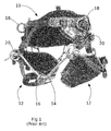
- FIG. 1 and 2 a known harness to which it might be applied is shown in Figures 1 and 2 .
- the main components of such a harness include a waist belt 10, leg loops 12, a bridge 14, an attachment eye 16, top Ds 18 and forward Ds 20.
- each forward D 20 lies to the outside of the user's leg 26.
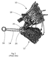
- a climbing rope 28 is connected to the attachment eye 16, typically by way of a carabiner, to carry the user's weight through the leg loops 12.
- the attachment eye 16 can float along and pivots upon the bridge 14 when the user moves from side to side. This gives the user unrestricted movement and means the harness adapts to the users shape when they twist, pivot and move, which is considered by users to be a particular advantage of this type of harness.
- EP-A-2 781 235 An improvement to this type of harness is disclosed in EP-A-2 781 235 . This proposes making a rigid interconnection between what is called here the forward Ds. However, this requires an extended, rigid component to be connected to the harness, which can restrict a user's freedom of movement and which removes some of the flexibility that is appreciated in this type of harness.
- An aim of this invention is to avoid or reduce this potential disadvantage without compromising the flexibility of this type of harness.
- this invention provides a harness for use by a person at height comprising:
- the aim of improving comfort is thereby achieved, without the need to provide any elongate, rigidly-attached component, and thereby maintain the flexibility of the harness.
- the bridge is typically an elongate flexible component, intended to be loaded under tension. It may take a wide variety of forms, being, for example, formed from rope (wire or textile), webbing, cable, or otherwise.
- the coupling means may be capable of distributing load along a length of the bridge that is a substantial proportion of the dimension of a user's body that is spanned by the bridge: that is to say, it may exceed 10%, 20%, 25%, 50% or 100% of that dimension.
- the coupling means may spread its load over a distance in the range of 100 mm to 500 mm or more.
- the coupling means may have a tubular body through which the bridge extends.
- the load is spaced apart on the bridge by the length of the tubular body.
- the coupling means may have a plurality of spaced guides through which the bridge passes. In such a case, the load is spaced apart on the bridge by the distance between the guides.
- the bridge makes sliding or rolling contact with the body while the harness is in use, which can cause parts of the body to wear over time. Therefore, it may be advantageous for those parts of the body with which the bridge makes contact may be formed as separate components that can be removed and replaced independently of other parts of the harness.
- each of these components may be configured such that it can be connected to the coupling means in a plurality of orientations such that if excessive wear occurs at one part of the component, it can be removed from the body and re-installed in a different orientation, whereby an unworn part of the component makes contact with the bridge.
- the coupling means is capable of loading the bridge at spaced-apart locations when in a first configuration, and in a second configuration, loads the bridge at closely-spaced locations.
- This allows a user to choose between maximising comfort and maximising freedom of movement.
- such embodiments may have loading components, such as loading arms, each of which carries a loading element, the distance between the loading elements determining the extent to which the load is spaced along the bridge.
- These loading components may be mutually movable (e.g., by pivoting, sliding, screwing, or moving telescopically) to adjust the spacing between the loading elements.
- a load-limiting means may be provided to enable the device to break non-catastrophically in the event that the load exceeds a safe threshold.
- the load-limiting means may include a breaker bolt or breaker link that will fail at a predetermined force to return to the second, closely-spaced and thus stronger configuration to enable a non-catastrophic collapse of the device. This may give the user the ability to carry on using the device in the closed position whilst being rescued or performing self-rescue.
- a load on the bridge exceeds a threshold, the loading components are caused to move towards their second configuration.
- connection means typically includes linking means that can be used to link the connection means to an external component, such as a carabiner or a sling.
- connection means permits pivotal movement between the connection means and the external component. Such pivotal movement is preferably permitted about more than one axis. Such axes are preferably normal to and parallel to the bridge in the region of the connection means.
- contact between the bridge and the connection means is made through components configured to minimise friction and/or abrasion with the bridge.
- contact between the bridge and the connection means may be made through rolling elements or through smooth and/or curved surfaces.
- the support element is typically a climbing line.
- an embodiment of the invention is a modification of the harness of Figures 1 and 2 and should be assumed to include all of the components of that harness.
- This embodiment comprises all of the components of that harness, with the exception of the attachment eye 16, which is replaced by a load-spreading assembly, as will now be described.
- the load-spreading assembly comprises a tubular body 30 which, in this embodiment, is formed from light alloy by forging, machining and/or casting.
- the body has a central, cylindrical passage 32 that extends lengthways, parallel to a long axis A, through it. End portions 34 of the cylindrical passage 32 are radiused, so as to present no sharp edges and reduce frictional forces in movement at the ends of the passage 32.
- the length of the passage in this embodiment is approximately 120 mm, but this may be varied to accommodate users of different sizes and a range of applications and working environments.
- the attachment point comprises a swivel connector 40 and two flange portions 42 of the body 30.
- the flange portions 42 have facing surfaces that are spaced apart and parallel to one another to opposite sides of the axis A. Centrally, an aperture is formed through each flange portion 42, these apertures being coaxial and transverse to the axis A. In the region of the flange portions 42, the passage 32 is open in a direction radially of the axis; however, this is for convenience of manufacture, and is not an essential feature of embodiments of this invention.
- the swivel connector 40 comprises a boss 46 and an eye 50, these being interconnected for free mutual rotation about a swivel axis B.
- the boss 46 has spaced parallel surfaces, and an aperture that extends through the boss between them (not shown).
- a pivot bolt 52 passes through the apertures in the flange portions 42 and the boss 46 and is retained by a nut 54 recessed into one of the flange portions 42. This allows the boss 46, and therefore the entire swivel connector 40, to pivot about a pivot axis C that is coaxial with the pivot bolt 52, as shown in Figure 8 .
- the bridge 14 of the harness passes through the cylindrical passage 32.
- a climbing rope is connected to the swivel connector, typically through a carabiner that passes through the eye 50.
- the position of the climbing rope can pivot and float with respect to the bridge by:
- the effect of this invention is that the component of the force in the bridge 14 that is resolved into an inwardly-directed force F i is reduced, and that the end potions of the bridge, which extend from the forward Ds 20, are held at an angle which causes less or no compression to the user's legs.
- the effect of this is to lessen pressure that is applied to a user's body during use of the harness, and thereby reduce the likelihood that it will cause discomfort.
- FIG. 10 An alternative embodiment of the invention is shown in Figures 10 , 11 and 12 .
- This embodiment includes a swivel connector 40 essentially the same as that described above.
- first and second arms 60, 70 are pivotally connected by a pivot bolt 62 and nut 64 to the boss 46 such that each arm 60, 70 can pivot against a respective one of the spaced parallel surfaces of the boss 46.
- the arms fork Remote from the pivot bolt 62, the arms fork, whereby a passage 66 through each arm is defined in a direction normal to the pivot axis C.
- Each passage 66 is closed by a cross-piece 68 of circular cross-section that extends across the fork parallel to the pivot axis C.
- a transverse bore 72 extends through the second arm 70 parallel to and close to the pivot bolt.
- Two bores 74, 76 extend through the first arm 60 parallel to and close to the pivot bolt.
- the arms 60, 70 can be disposed in a closed position ( Fig 10 ) in which they are pivoted together about the pivot bolt 62 to reduce to a minimum the distance between the passages 66.
- the bore 72 of the second arm is in alignment with one of the bores 74 in the first arm 60, and a pin can be inserted into these bores 72, 74 to secure the arms 60, 70 in that position.
- the arms 60, 70 can be disposed in an open position ( Fig 11 ) in which they are pivoted apart about the pivot bolt 62 to maximise the distance between the passages 66.
- the bore 72 of the second arm is in alignment with the other one of the bores 76 in the first arm 60, and a pin can be inserted into these bores 72, 76 to secure the arms 60, 70 in the open position.
- the bridge 14 of the harness passes through the passages 66 in the two arms 60, 70.
- a climbing rope is connected to the swivel connector, typically through a carabiner that passes through the eye 50.
- the bridge 14 can slide through the passages 66 and over the crosspieces 68.
- a user can move the arms 60, 70 between their closed and their open position as required. In the closed position, a small attachment width on bridge 14 is created to maximise a user's freedom of movement. In the open position, the connection with the bridge is larger, thereby increasing the comfort of the harness.
- the cross pieces 68 may include rollers to reduce the friction applied by the arms as they pass along the bridge 14. Another consequence of this to reduce wear on the bridge 14. A similar arrangement may be provided in other embodiments.
- the assembly as a whole will be strongest when the arms 60, 70 are in the closed position. Therefore, it may be advantageous for the assembly to be configured such that the arms 60, 70 return to the closed condition if normal service loading is exceeded, and well before loading on the assembly approaches an ultimate maximum load.
- a break-out portion 80 of the material of the first arm 60 that surrounds the bore 76 used when the arms 60, 70 are in the open position is of reduced thickness.
- the break-out portion 80 is located at the part of the first arm 60 that react force F P with the pin 78.
- the pin 78 will be driven though break-out region 80 in the event that the force F B applied by the bridge 14 to the arms 60, 70 exceeds a threshold. With careful design of the thickness and position of material, this can be caused to happen at loads significantly below the ultimate failure load of the assembly (but in excess of that encountered in normal use) and relatively progressively, as compared with catastrophic failure that might occur in the event of breakage under extreme loading.
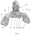
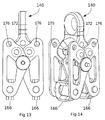
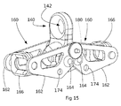
- FIG. 13 to 15 is functionally similar to that of the embodiment of Figures 10 to 12 .
- two arms 160 are pivotally connected to a central boss 140 that has a securing eye 142.
- boss 140 shown is a one-piece, solid component, it could equally be of a swivelling type, as described above.
- the arms 160 each comprises two parallel side plate members 162 connected to opposite sides of the boss 140 by a pivot 164 whereby the arms can pivot with respect to the boss 140 about respective parallel pivot axes.
- a guide ring 166 interconnects the arms 162 remote from the pivots, the guide ring 166 being free to pivot with respect to the arms 160 about an axis parallel to the pivot axes of the arms 160.
- the guide rings 166 each have a rounded square shape and have inwardly convex curved surfaces to allow smooth passage of the bridge through them. The pivotal attachment of the guide rings 166 to the arms 160 ensures that they always adopt an alignment that allows free passage of the bridge 14 though them.
- the plate members 162 have first and second apertures 174, 176 with align with a transverse bore 172 in the boss 140 with, respectively, the arms 160 in a closed and an open position.
- a pin 180 is inserted through the apertures 174 or 176, as the case may be, and the bore 172.
- the pin 180 can be selected to have a strength that will cause it to fail in the event that the load applied to the arms 160 by the bridge exceeds a threshold, thereby allowing the arms 160 to return to the closed position.
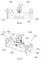
- FIG. 16 to 19 comprises a central boss 240 with two (in this case) securing eyes 242, 244 carried on a transverse flange portion 246.
- Coaxial externally-threaded spigots 248 extend from the flange portion 246, each having an axial through passage that also extends through the flange portion 246.
- a respective sleeve 250 is carried on each of the spigots 248, the sleeve having an internal thread in engagement with the thread of the spigot 248.
- An outer face of each sleeve has an opening 254 in communication with its interior, the opening being surrounded by a concave curved surface.
- the bridge 14 is passed through the sleeves 250 and the boss 240.
- the length of the loading applied to the bridge 14 is determined by the distance between the openings 254 of the sleeves 250, which can be adjusted by rotation of the sleeves 250 with respect to the boss to cause them to move axially along the spigots 248. It may be advantageous for the threads of the two spigots 248 (and so, of the sleeves 250) to be of opposite hands, whereby the same action on the part of a user causes the same effect (lengthening or shortening) to each of the sleeves.
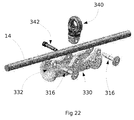
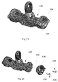
- FIG. 20 to 22 A variation on the first embodiment of the invention is shown in Figures 20 to 22 .
- a slot 310 extends radially through each tubular passage 332 of the body 330.
- the body is generally U-shaped in section.
- flanges 312 project form the body, parallel and facing one another to opposite sides of each slot 310.
- a bore extends through each flange 312, the bores of each pair of flanges 312 being coaxial.
- a closing pin 316 is provided at each end portion 334. In a closed condition, the closing pin 316 passes through both bores.
- the swivel connector 340 is secured between the flanges by a removable pivot pin 342.
- each closing pin 316 is withdrawn, and both bores and the pivot pin 342 are removed to allow the swivel connector to be separated from the body 330.
- a rope bridge 14 or other connecting element can pass into or out of the body 330. This allows the apparatus to be applied to or removed from a harness without the need to free one end of the rope bridge.
- each annular component has a central opening that, at an inner end, connects with one end of the cylindrical passage 432, and, extending outwardly from there, is radiused so as to present no sharp edges and reduce frictional forces in movement of a rope or other element extending out of the end of the passage 432. This is exactly the same function as described with reference to the end portions 34 of the first embodiment.
- the annular components 436 are each secured to the tubular body 430 by several (two, in this embodiment) cap screws 438 that pass through the annular components 436.
- the stem of each cap screw 438 is received in a tapped hole in an end surface of the tubular body 430, and the head of each cap screw 438 is received in a recess in the annular component.
- the annular components 436 are rotationally symmetrical. If, during use, wear occurs on part of an annular component 436 through rubbing contact with the bridge 14, it can be removed from the body 430, rotated and re-attached such that a different, unworn part of the annular component 436 makes contact with the bridge 14.
- the annular components 436 can be replaced independently of other components of the harness in the event that wear has occurred at all possible angular locations.
Landscapes
- Health & Medical Sciences (AREA)
- General Health & Medical Sciences (AREA)
- Business, Economics & Management (AREA)
- Emergency Management (AREA)
- Physical Education & Sports Medicine (AREA)
- Emergency Lowering Means (AREA)
Abstract
Description
- This invention relates to harnesses. Specifically, it relates to harnesses that are intended for use by a person at height, such as a climber or a person working at height.
- Users who work at height may spend many hours at a time in a harness to perform work tasks on structures, buildings and trees. A typical user will wear an industrial climbing harness and be attached to a climbing system to enable them to position themselves in a location to perform the work tasks required. The harness must not only provide comfortable and safe support for the user, it must also allow the user freedom of movement to climb and manoeuvre themselves within their working environment.
- A commercial user may spend many hours at a time in a harness when working in this way. Therefore, any potential source of discomfort in the harness is likely to lead to actual discomfort over time, which may ultimately lead to a reduction in the time a user can spend working in the harness. It is therefore in both the interest of productivity and of the welfare of the user to ensure that potential sources of discomfort in a work harness are, so far as is possible, minimised.
- In general, any part of the harness which is likely to cause a localised increase in the pressure applied to a user's body is a potential source of discomfort, and it is recognised that steps should be taken in designing a harness to avoid any potential source of raised pressure.
- One approach to solving this problem is to provide a rigid or semi-rigid platform that acts as a seat to provide the primary support for a user's weight. For example, this arrangement can be seen in
US-A-2009/314578 . Comfort may potentially be further improved by providing a bosun's chair arrangement that provides a broad and potentially cushioned sitting platform. However, the presence of a rigid structure in both of these arrangements can restrict a user's freedom of movement, and can be unwieldy when working in a partially-obstructed space, such as amongst branches of a tree canopy or manoeuvring through a manhole. Therefore, many users still prefer a fabric harness made of flexible material including ropes and webbing. - To place the invention in context, a known harness to which it might be applied is shown in
Figures 1 and2 . The main components of such a harness include awaist belt 10,leg loops 12, abridge 14, anattachment eye 16,top Ds 18 and forwardDs 20. Thebridge 14, which in this example is a length of fabric rope, extends between eyes on the respective forward Ds and theattachment eye 16 surrounds and can slide along thebridge 14. - For use, a user is secured within the harness with the
waist belt 10 around their waist, and with eachleg loop 12 surrounding a respective one of the user's thighs. In this position, eachforward D 20 lies to the outside of the user'sleg 26. Aclimbing rope 28 is connected to theattachment eye 16, typically by way of a carabiner, to carry the user's weight through theleg loops 12. Theattachment eye 16 can float along and pivots upon thebridge 14 when the user moves from side to side. This gives the user unrestricted movement and means the harness adapts to the users shape when they twist, pivot and move, which is considered by users to be a particular advantage of this type of harness. - A problem arises with this arrangement because the
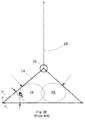
bridge 14 extends in two lengths from theattachment eye 16, so that the force applied to each of theforward Ds 20 has an inward component Fi that is directed towards the other of theforward Ds 20 as well as a force Fo that acts away from the user. This is shown diagrammatically inFigures 3A . Such harnesses are wrapped around a user, with a U-shaped rear part applying the load to the user. When loaded from the ventral attachment point, the harness compresses the width of the loaded U shape, reducing the loaded contact area and compressing the body of the user. This inward component can result in localised pressure, and possible discomfort after long-term use. Therefore, known harnesses put stress and pressure on the user due to constricting the user's hips, legs and buttock area when under load due to the single attachment eye point which is of limited width. One attempted solution is to add a seat to the rear of the harness, as illustrated inFigure 3B , however there is still discomfort because of the rigid nature of the seat. Moreover, harness seats are cumbersome and can restrict the movement and rope positioning ability of the user due to the position behind the legs and rigid nature of the seat. - An improvement to this type of harness is disclosed in
EP-A-2 781 235 . This proposes making a rigid interconnection between what is called here the forward Ds. However, this requires an extended, rigid component to be connected to the harness, which can restrict a user's freedom of movement and which removes some of the flexibility that is appreciated in this type of harness. - An aim of this invention is to avoid or reduce this potential disadvantage without compromising the flexibility of this type of harness.
- To this end, from a first aspect, this invention provides a harness for use by a person at height comprising:
- a plurality of flexible harness elements, each of which, when in use, encircles part of a user's body, wherein some or all of the harness elements include a connection piece;
- a bridge extending between a respective connection piece of two or more harness elements, the bridge extending across a part of a user's body;
- connection means connected to the bridge to convey at least part of a user's weight from the harness to a support element; wherein:
- the connection means has coupling means that at least partially surrounds and that can move along the bridge and is capable of loading the bridge at spaced-apart locations.
- The aim of improving comfort is thereby achieved, without the need to provide any elongate, rigidly-attached component, and thereby maintain the flexibility of the harness.
- The bridge is typically an elongate flexible component, intended to be loaded under tension. It may take a wide variety of forms, being, for example, formed from rope (wire or textile), webbing, cable, or otherwise.
- The coupling means may be capable of distributing load along a length of the bridge that is a substantial proportion of the dimension of a user's body that is spanned by the bridge: that is to say, it may exceed 10%, 20%, 25%, 50% or 100% of that dimension. For example, where the bridge extends across a user's trunk or hips, the coupling means may spread its load over a distance in the range of 100 mm to 500 mm or more.
- For example, the coupling means may have a tubular body through which the bridge extends. In such a case, the load is spaced apart on the bridge by the length of the tubular body. Alternatively, the coupling means may have a plurality of spaced guides through which the bridge passes. In such a case, the load is spaced apart on the bridge by the distance between the guides. The bridge makes sliding or rolling contact with the body while the harness is in use, which can cause parts of the body to wear over time. Therefore, it may be advantageous for those parts of the body with which the bridge makes contact may be formed as separate components that can be removed and replaced independently of other parts of the harness. Advantageously, each of these components may be configured such that it can be connected to the coupling means in a plurality of orientations such that if excessive wear occurs at one part of the component, it can be removed from the body and re-installed in a different orientation, whereby an unworn part of the component makes contact with the bridge.
- In some embodiments of the invention, the coupling means is capable of loading the bridge at spaced-apart locations when in a first configuration, and in a second configuration, loads the bridge at closely-spaced locations. This allows a user to choose between maximising comfort and maximising freedom of movement. For example, such embodiments (or others) may have loading components, such as loading arms, each of which carries a loading element, the distance between the loading elements determining the extent to which the load is spaced along the bridge. These loading components may be mutually movable (e.g., by pivoting, sliding, screwing, or moving telescopically) to adjust the spacing between the loading elements.
- In these embodiments, due to the large loads apparent on the spaced-apart locations, a load-limiting means may be provided to enable the device to break non-catastrophically in the event that the load exceeds a safe threshold. The load-limiting means may include a breaker bolt or breaker link that will fail at a predetermined force to return to the second, closely-spaced and thus stronger configuration to enable a non-catastrophic collapse of the device. This may give the user the ability to carry on using the device in the closed position whilst being rescued or performing self-rescue. Thus, when in the first configuration, a load on the bridge exceeds a threshold, the loading components are caused to move towards their second configuration.
- The connection means typically includes linking means that can be used to link the connection means to an external component, such as a carabiner or a sling. Most advantageously, the connection means permits pivotal movement between the connection means and the external component. Such pivotal movement is preferably permitted about more than one axis. Such axes are preferably normal to and parallel to the bridge in the region of the connection means.
- Preferably, contact between the bridge and the connection means is made through components configured to minimise friction and/or abrasion with the bridge. For example, contact between the bridge and the connection means may be made through rolling elements or through smooth and/or curved surfaces.
- The support element is typically a climbing line.
- Embodiments of the invention will now be described in detail, by way of example, and with reference to the accompanying drawings, in which:
-
Figures 1 and2 show a conventional harness to which embodiments of the present invention might be applied, and have already been discussed; -
Figures 3A and3B are diagrams that show forces acting within the harness ofFigures 1 and2 ; -
Figures 4 and 5 are side and end views of a load-spreading assembly being a component of an embodiment of the invention; -
Figure 6 is a cross-sectional view of the load-spreading assembly ofFigures 4 and 5 ; -
Figure 7 is a diagonal view of the load-spreading assembly ofFigures 4 and 5 showing it in place on a rope; -
Figure 8 is a view of the load-spreading assembly ofFigures 4 to 6 in an alternative configuration; -
Figure 9 is a diagram equivalent toFigure 3 that shows forces acting within the harness that is an embodiment of the invention; -
Figures 10 ,11 and12 are diagonal views of a load-spreading assembly being a component of an alternative embodiment of the invention in closed and open configurations,Figures 11 and12 showing opposite sides of the assembly; -
Figures 13 and 14 show a further embodiment of the invention in a first configuration; -
Figure 15 shows the embodiment ofFigures 13 and 14 in a second configuration; -
Figures 16 and 17 show a further embodiment of the invention in a first configuration; -
Figures 18 and 19 show the embodiment ofFigures 14 and15 in a second configuration; -
Figures 20 and 21 show a variation of the embodiment ofFigures 4 to 8 ; -
Figure 22 is an exploded view of the embodiment ofFigures 20 and 21 ; and -
Figures 23 and 24 show a variation that can be applied to embodiments of this invention. - With reference to the drawings, an embodiment of the invention is a modification of the harness of
Figures 1 and2 and should be assumed to include all of the components of that harness. This embodiment comprises all of the components of that harness, with the exception of theattachment eye 16, which is replaced by a load-spreading assembly, as will now be described. - The load-spreading assembly comprises a
tubular body 30 which, in this embodiment, is formed from light alloy by forging, machining and/or casting. The body has a central,cylindrical passage 32 that extends lengthways, parallel to a long axis A, through it.End portions 34 of thecylindrical passage 32 are radiused, so as to present no sharp edges and reduce frictional forces in movement at the ends of thepassage 32. The length of the passage in this embodiment is approximately 120 mm, but this may be varied to accommodate users of different sizes and a range of applications and working environments. - Centrally along the length of the body there is an attachment point. The attachment point comprises a
swivel connector 40 and twoflange portions 42 of thebody 30. - The
flange portions 42 have facing surfaces that are spaced apart and parallel to one another to opposite sides of the axis A. Centrally, an aperture is formed through eachflange portion 42, these apertures being coaxial and transverse to the axis A. In the region of theflange portions 42, thepassage 32 is open in a direction radially of the axis; however, this is for convenience of manufacture, and is not an essential feature of embodiments of this invention. Theswivel connector 40 comprises aboss 46 and aneye 50, these being interconnected for free mutual rotation about a swivel axis B. Theboss 46 has spaced parallel surfaces, and an aperture that extends through the boss between them (not shown). Apivot bolt 52 passes through the apertures in theflange portions 42 and theboss 46 and is retained by anut 54 recessed into one of theflange portions 42. This allows theboss 46, and therefore theentire swivel connector 40, to pivot about a pivot axis C that is coaxial with thepivot bolt 52, as shown inFigure 8 . - In use, the
bridge 14 of the harness passes through thecylindrical passage 32. A climbing rope is connected to the swivel connector, typically through a carabiner that passes through theeye 50. As with the conventional harness, the position of the climbing rope can pivot and float with respect to the bridge by: - the
tubular body 30 sliding along thebridge 14, free sliding being ensured by the provision of theradiused end portions 34; - the
swivel connector 40 pivoting with respect to thebody 30 about the axis C; and - the
eye 50 pivoting with respect to theboss 46, and therefore thebody 30, about the swivel axis B. - This allows a similar freedom of movement as does a conventional harness.
- As can be seen by comparing
Figures 9 and3 , the effect of this invention is that the component of the force in thebridge 14 that is resolved into an inwardly-directed force Fi is reduced, and that the end potions of the bridge, which extend from theforward Ds 20, are held at an angle which causes less or no compression to the user's legs. The effect of this is to lessen pressure that is applied to a user's body during use of the harness, and thereby reduce the likelihood that it will cause discomfort. - An alternative embodiment of the invention is shown in
Figures 10 ,11 and12 . This embodiment includes aswivel connector 40 essentially the same as that described above. - In this embodiment, first and
second arms pivot bolt 62 andnut 64 to theboss 46 such that eacharm boss 46. Remote from thepivot bolt 62, the arms fork, whereby apassage 66 through each arm is defined in a direction normal to the pivot axis C. Eachpassage 66 is closed by across-piece 68 of circular cross-section that extends across the fork parallel to the pivot axis C. Atransverse bore 72 extends through thesecond arm 70 parallel to and close to the pivot bolt. Two bores 74, 76 extend through thefirst arm 60 parallel to and close to the pivot bolt. - The
arms Fig 10 ) in which they are pivoted together about thepivot bolt 62 to reduce to a minimum the distance between thepassages 66. In this position, thebore 72 of the second arm is in alignment with one of thebores 74 in thefirst arm 60, and a pin can be inserted into thesebores arms arms Fig 11 ) in which they are pivoted apart about thepivot bolt 62 to maximise the distance between thepassages 66. In this position, thebore 72 of the second arm is in alignment with the other one of thebores 76 in thefirst arm 60, and a pin can be inserted into thesebores arms - In use, the
bridge 14 of the harness passes through thepassages 66 in the twoarms eye 50. Thebridge 14 can slide through thepassages 66 and over thecrosspieces 68. While in use, a user can move thearms bridge 14 is created to maximise a user's freedom of movement. In the open position, the connection with the bridge is larger, thereby increasing the comfort of the harness. - The
cross pieces 68 may include rollers to reduce the friction applied by the arms as they pass along thebridge 14. Another consequence of this to reduce wear on thebridge 14. A similar arrangement may be provided in other embodiments. - It will be seen that when the harness is bearing a user's weight and the
arms arms bridge 14 urge them towards the closed position, this force being resisted by thepin 78 and the material surrounding thebores arms arms - In this embodiment, a break-out
portion 80 of the material of thefirst arm 60 that surrounds thebore 76 used when thearms portion 80 is located at the part of thefirst arm 60 that react force FP with thepin 78. Thepin 78 will be driven though break-outregion 80 in the event that the force FB applied by thebridge 14 to thearms - The embodiment of
Figure 13 to 15 is functionally similar to that of the embodiment ofFigures 10 to 12 . In this embodiment, twoarms 160 are pivotally connected to acentral boss 140 that has a securingeye 142. Although theboss 140 shown is a one-piece, solid component, it could equally be of a swivelling type, as described above. - The
arms 160 each comprises two parallelside plate members 162 connected to opposite sides of theboss 140 by apivot 164 whereby the arms can pivot with respect to theboss 140 about respective parallel pivot axes. Aguide ring 166 interconnects thearms 162 remote from the pivots, theguide ring 166 being free to pivot with respect to thearms 160 about an axis parallel to the pivot axes of thearms 160. The guide rings 166 each have a rounded square shape and have inwardly convex curved surfaces to allow smooth passage of the bridge through them. The pivotal attachment of the guide rings 166 to thearms 160 ensures that they always adopt an alignment that allows free passage of thebridge 14 though them. Theplate members 162 have first andsecond apertures transverse bore 172 in theboss 140 with, respectively, thearms 160 in a closed and an open position. To retain thearms 160 in either position, apin 180 is inserted through theapertures bore 172. Thepin 180 can be selected to have a strength that will cause it to fail in the event that the load applied to thearms 160 by the bridge exceeds a threshold, thereby allowing thearms 160 to return to the closed position. - The embodiment of
Figures 16 to 19 comprises acentral boss 240 with two (in this case) securingeyes transverse flange portion 246. Coaxial externally-threadedspigots 248 extend from theflange portion 246, each having an axial through passage that also extends through theflange portion 246. Arespective sleeve 250 is carried on each of thespigots 248, the sleeve having an internal thread in engagement with the thread of thespigot 248. An outer face of each sleeve has anopening 254 in communication with its interior, the opening being surrounded by a concave curved surface. - In use, the
bridge 14 is passed through thesleeves 250 and theboss 240. The length of the loading applied to thebridge 14 is determined by the distance between theopenings 254 of thesleeves 250, which can be adjusted by rotation of thesleeves 250 with respect to the boss to cause them to move axially along thespigots 248. It may be advantageous for the threads of the two spigots 248 (and so, of the sleeves 250) to be of opposite hands, whereby the same action on the part of a user causes the same effect (lengthening or shortening) to each of the sleeves. - A variation on the first embodiment of the invention is shown in
Figures 20 to 22 . In this embodiment, aslot 310 extends radially through eachtubular passage 332 of thebody 330. Thus, the body is generally U-shaped in section. In the region of theend portions 334 of the tubular passage,flanges 312 project form the body, parallel and facing one another to opposite sides of eachslot 310. A bore extends through eachflange 312, the bores of each pair offlanges 312 being coaxial. Aclosing pin 316 is provided at eachend portion 334. In a closed condition, theclosing pin 316 passes through both bores. Theswivel connector 340 is secured between the flanges by aremovable pivot pin 342. - With the
pins 316 in the closed condition, and theswivel connector 340 retained by thepin 342, a rope bridge passing through thebody 30 is retained within thebody 330 and a harness to which the load spreading assembly is attached will operate in the same way as the first embodiment. In an open position, each closingpin 316 is withdrawn, and both bores and thepivot pin 342 are removed to allow the swivel connector to be separated from thebody 330. In this configuration, arope bridge 14 or other connecting element can pass into or out of thebody 330. This allows the apparatus to be applied to or removed from a harness without the need to free one end of the rope bridge. - With reference now to
Figures 23 and 24 there is shown a modification that can be applied to many of the embodiments described above. This particular implementation of the modification is a variation of the embodiment ofFigures 4 to 8 , but the skilled person will readily understand how it could be applied to other embodiments. - In this modification, the
end portions 434 of thetubular body 430 are formed on separateannular components 436. Each annular component has a central opening that, at an inner end, connects with one end of thecylindrical passage 432, and, extending outwardly from there, is radiused so as to present no sharp edges and reduce frictional forces in movement of a rope or other element extending out of the end of thepassage 432. This is exactly the same function as described with reference to theend portions 34 of the first embodiment. - The
annular components 436 are each secured to thetubular body 430 by several (two, in this embodiment)cap screws 438 that pass through theannular components 436. The stem of eachcap screw 438 is received in a tapped hole in an end surface of thetubular body 430, and the head of eachcap screw 438 is received in a recess in the annular component. - The
annular components 436 are rotationally symmetrical. If, during use, wear occurs on part of anannular component 436 through rubbing contact with thebridge 14, it can be removed from thebody 430, rotated and re-attached such that a different, unworn part of theannular component 436 makes contact with thebridge 14. Theannular components 436 can be replaced independently of other components of the harness in the event that wear has occurred at all possible angular locations.
Claims (15)
- A harness for use by a person at height comprising:a plurality of flexible harness elements (10, 12), each of which, when in use, encircles part of a user's body, wherein some or all of the harness elements include a connection piece (20);a bridge (14) extending between a respective connection piece of two or more harness elements, the bridge extending across a part of a user's body;connection means connected to the bridge (14) to convey at least part of a user's weight from the harness to a support element; characterised in that:the connection means has coupling means (30) that at least partially surrounds and that can move along the bridge (14) and is capable of loading the bridge at spaced-apart locations.
- A harness according to claim 1 in which the bridge (14) is an elongate flexible component, intended to be loaded under tension.
- A harness according to claim 1 or claim 2 in which the coupling means is capable of distributing load along a length in excess of 10%, 20%, 25%, 50% or 100% of the dimension of a user's body that is spanned by the bridge.
- A harness according to any preceding claim in which the coupling means is capable of distributing load along a length of 100 mm to 500 mm.
- A harness according to any preceding claim in which the coupling means has a tubular body (30) or a plurality of spaced guides (66, 166) through which the bridge passes.
- A harness according to any preceding claim in which those parts of the coupling means with which the bridge makes contact are formed as separate components (436) that can be removed and replaced independently of other parts of the harness.
- A harness according to claim 6 in which each separate component (436) is configured such that it can be connected to the coupling means in a plurality of orientations such that if excessive wear occurs at one part of the component, it can be removed from the body and re-installed in a different orientation whereby, in subsequent use, an unworn part of the component makes contact with the bridge
- A harness according to any preceding claim in which the coupling means is capable of loading the bridge (14) at spaced-apart locations when in a first configuration, and in a second configuration, at locations that are spaced apart by a distance that is less than in the first configuration.
- A harness according to claim 8 having loading components (60, 70; 250), each of which carries a loading element, the loading components being mutually movable to adjust the distance between the loading elements, the distance between the loading elements determining the extent to which the load is spaced along the bridge.
- A harness according to claim 9 in which the loading components are mutually pivotable with respect to one another and/or are in threaded engagement with one another or with a common linking component.
- A harness according to any one of claims 8 to 10 which, when in the first configuration, a load on the bridge exceeds a threshold, the loading components are caused to move towards their second configuration.
- A harness according to any preceding claim in which the coupling means has a closure (316, 342) that can be opened to remove or introduce the bridge from or to the coupling means.
- A harness according to any preceding claim in which the connection means includes linking means (340) that can be used to link the connection means to an external component, the connection means permitting pivotal movement about axes that are normal to and parallel to the bridge in the region of the connection means between the connection means and the external component.
- A harness according to any preceding claim in which contact between the bridge and the connection means is made through components configured to minimise friction and/or abrasion with the bridge.
- A harness according to claim 14 in which contact between the bridge and the connection means is made through rolling elements or smooth curved surfaces.
Applications Claiming Priority (1)
| Application Number | Priority Date | Filing Date | Title |
|---|---|---|---|
| GB1515563.3A GB2541905B (en) | 2015-09-02 | 2015-09-02 | Harnesses |
Publications (2)
| Publication Number | Publication Date |
|---|---|
| EP3138608A1 true EP3138608A1 (en) | 2017-03-08 |
| EP3138608B1 EP3138608B1 (en) | 2019-11-20 |
Family
ID=54326684
Family Applications (1)
| Application Number | Title | Priority Date | Filing Date |
|---|---|---|---|
| EP16184748.8A Active EP3138608B1 (en) | 2015-09-02 | 2016-08-18 | Harnesses |
Country Status (3)
| Country | Link |
|---|---|
| US (1) | US20170056692A1 (en) |
| EP (1) | EP3138608B1 (en) |
| GB (1) | GB2541905B (en) |
Cited By (3)
| Publication number | Priority date | Publication date | Assignee | Title |
|---|---|---|---|---|
| EP3772363A1 (en) * | 2019-08-06 | 2021-02-10 | Skylotec GmbH | Belt for applying to a person that needs to be secured with a belt bridge |
| WO2022123275A1 (en) | 2020-12-11 | 2022-06-16 | Treeemagineers Ltd | Harnesses |
| EP4019093A1 (en) | 2020-12-22 | 2022-06-29 | Treemagineers Ltd | Harnesses |
Families Citing this family (4)
| Publication number | Priority date | Publication date | Assignee | Title |
|---|---|---|---|---|
| CN109847227A (en) * | 2018-10-16 | 2019-06-07 | 国家电网有限公司 | A kind of high-altitude work safety belt hanging point fixing device |
| GB2580674B (en) * | 2019-01-22 | 2022-12-07 | Checkmate Lifting & Safety Ltd | Coupler for a fall protection device |
| US20220305307A1 (en) * | 2021-03-24 | 2022-09-29 | Pigeon Mountain Industries, Inc. | Self-adjusting safety harness |
| GB2614909A (en) * | 2022-01-24 | 2023-07-26 | Excalibur Wales Ltd | Attachment assembly |
Citations (10)
| Publication number | Priority date | Publication date | Assignee | Title |
|---|---|---|---|---|
| US2254179A (en) * | 1940-05-23 | 1941-08-26 | John F Fonder | Safety seat |
| US4546851A (en) * | 1982-11-03 | 1985-10-15 | Brennan Daniel F | Tree climbing apparatus |
| US4630563A (en) * | 1983-11-24 | 1986-12-23 | Siegried Pertramer | Trapeze belt or harness for windsurfing |
| WO1988005396A1 (en) * | 1987-01-21 | 1988-07-28 | Duncan Place | Sailboard harness |
| US6508186B2 (en) * | 2001-01-11 | 2003-01-21 | Neil Pryde Limited | Quick release locking device for a strap |
| GB2398821A (en) * | 2003-02-26 | 2004-09-01 | Central | Workmen's safety devices for use with fixed track |
| GB2443284A (en) * | 2006-08-14 | 2008-04-30 | Zhik Pty Ltd | An adjustable harness for sailing and sail boarding |
| US20090314578A1 (en) * | 2008-06-18 | 2009-12-24 | Zedel | Roping harness with improved seat |
| US8333262B1 (en) * | 2008-11-12 | 2012-12-18 | Buckingham Manufacturing Company, Inc. | Reconfigurable, modular ergonomic sit harness or saddle |
| EP2781235A2 (en) * | 2013-03-19 | 2014-09-24 | A. Haberkorn & Co GmbH | Climbing harness with spacer |
Family Cites Families (7)
| Publication number | Priority date | Publication date | Assignee | Title |
|---|---|---|---|---|
| US2581772A (en) * | 1946-10-04 | 1952-01-08 | Rose Mfg Company | Safety belt |
| US4059871A (en) * | 1976-09-17 | 1977-11-29 | Swager William E | Clamping device with locking trigger arm |
| GB9110900D0 (en) * | 1991-05-21 | 1991-07-10 | Barrow Hepburn Sala Ltd | Safety apparatus |
| FR2753303B1 (en) * | 1996-09-12 | 1998-12-04 | Centre Nat Rech Scient | ENERGY FILTER, ELECTRONIC TRANSMISSION MICROSCOPE AND METHOD FOR FILTERING ENERGY THEREOF |
| GB2370312B (en) * | 2000-11-29 | 2003-08-13 | Uniline Safety Systems Ltd | Attachment device for a safety line |
| US8973705B2 (en) * | 2010-09-01 | 2015-03-10 | Climb Tech, Llc | Swivel D-ring attachment point |
| CH704409B1 (en) * | 2011-01-31 | 2015-09-15 | Kanopeo Gmbh | Pulley belay line system continues. |
-
2015
- 2015-09-02 GB GB1515563.3A patent/GB2541905B/en active Active
-
2016
- 2016-08-18 EP EP16184748.8A patent/EP3138608B1/en active Active
- 2016-08-26 US US15/248,513 patent/US20170056692A1/en active Pending
Patent Citations (10)
| Publication number | Priority date | Publication date | Assignee | Title |
|---|---|---|---|---|
| US2254179A (en) * | 1940-05-23 | 1941-08-26 | John F Fonder | Safety seat |
| US4546851A (en) * | 1982-11-03 | 1985-10-15 | Brennan Daniel F | Tree climbing apparatus |
| US4630563A (en) * | 1983-11-24 | 1986-12-23 | Siegried Pertramer | Trapeze belt or harness for windsurfing |
| WO1988005396A1 (en) * | 1987-01-21 | 1988-07-28 | Duncan Place | Sailboard harness |
| US6508186B2 (en) * | 2001-01-11 | 2003-01-21 | Neil Pryde Limited | Quick release locking device for a strap |
| GB2398821A (en) * | 2003-02-26 | 2004-09-01 | Central | Workmen's safety devices for use with fixed track |
| GB2443284A (en) * | 2006-08-14 | 2008-04-30 | Zhik Pty Ltd | An adjustable harness for sailing and sail boarding |
| US20090314578A1 (en) * | 2008-06-18 | 2009-12-24 | Zedel | Roping harness with improved seat |
| US8333262B1 (en) * | 2008-11-12 | 2012-12-18 | Buckingham Manufacturing Company, Inc. | Reconfigurable, modular ergonomic sit harness or saddle |
| EP2781235A2 (en) * | 2013-03-19 | 2014-09-24 | A. Haberkorn & Co GmbH | Climbing harness with spacer |
Cited By (6)
| Publication number | Priority date | Publication date | Assignee | Title |
|---|---|---|---|---|
| EP3772363A1 (en) * | 2019-08-06 | 2021-02-10 | Skylotec GmbH | Belt for applying to a person that needs to be secured with a belt bridge |
| WO2022123275A1 (en) | 2020-12-11 | 2022-06-16 | Treeemagineers Ltd | Harnesses |
| AU2021396591B2 (en) * | 2020-12-11 | 2022-12-01 | Treemagineers Ltd | Harnesses |
| EP4190407A1 (en) | 2020-12-11 | 2023-06-07 | Treemagineers Ltd. | Harnesses |
| AU2023201149B2 (en) * | 2020-12-11 | 2025-05-08 | Treemagineers Ltd | Harnesses |
| EP4019093A1 (en) | 2020-12-22 | 2022-06-29 | Treemagineers Ltd | Harnesses |
Also Published As
| Publication number | Publication date |
|---|---|
| GB2541905A (en) | 2017-03-08 |
| EP3138608B1 (en) | 2019-11-20 |
| GB2541905B (en) | 2018-05-16 |
| US20170056692A1 (en) | 2017-03-02 |
| GB201515563D0 (en) | 2015-10-14 |
Similar Documents
| Publication | Publication Date | Title |
|---|---|---|
| EP3138608B1 (en) | Harnesses | |
| US20170120087A1 (en) | Protective equipment | |
| US10232199B2 (en) | Integral safety harness connector assembly | |
| US20230065262A1 (en) | Harnesses | |
| CN112770816B (en) | Equipment for supporting people at height | |
| CN107261355B (en) | Safety belt | |
| US8312965B2 (en) | Belay and abseiling apparatus for single or double rope | |
| US10799732B2 (en) | Harness | |
| US8973705B2 (en) | Swivel D-ring attachment point | |
| US9027707B2 (en) | Convertible safety harness | |
| US10994159B2 (en) | Harness for breathing apparatus | |
| US20210023400A1 (en) | Seat for safety harness | |
| WO2019051055A1 (en) | Harness with pivoting hip connection | |
| US9643054B2 (en) | Knee ascender assembly for rope climbing | |
| US12053061B2 (en) | Buckle assembly and harness comprising the same | |
| KR200492490Y1 (en) | Safety tower for power transmission tower | |
| EP4096796B1 (en) | Lanyard assembly | |
| EP4035743A1 (en) | Harnesses | |
| JP7266857B2 (en) | back support frame | |
| EP3919139A1 (en) | Roping harness | |
| EP3512609A1 (en) | Harness connector and harness | |
| JP2014532818A (en) | Belt fastener and chin strap of protective helmet with the same | |
| KR20210043852A (en) | Sliding type safety belt for preventing fall |
Legal Events
| Date | Code | Title | Description |
|---|---|---|---|
| PUAI | Public reference made under article 153(3) epc to a published international application that has entered the european phase |
Free format text: ORIGINAL CODE: 0009012 |
|
| STAA | Information on the status of an ep patent application or granted ep patent |
Free format text: STATUS: THE APPLICATION HAS BEEN PUBLISHED |
|
| AK | Designated contracting states |
Kind code of ref document: A1 Designated state(s): AL AT BE BG CH CY CZ DE DK EE ES FI FR GB GR HR HU IE IS IT LI LT LU LV MC MK MT NL NO PL PT RO RS SE SI SK SM TR |
|
| AX | Request for extension of the european patent |
Extension state: BA ME |
|
| STAA | Information on the status of an ep patent application or granted ep patent |
Free format text: STATUS: REQUEST FOR EXAMINATION WAS MADE |
|
| STAA | Information on the status of an ep patent application or granted ep patent |
Free format text: STATUS: EXAMINATION IS IN PROGRESS |
|
| 17P | Request for examination filed |
Effective date: 20170908 |
|
| RBV | Designated contracting states (corrected) |
Designated state(s): AL AT BE BG CH CY CZ DE DK EE ES FI FR GB GR HR HU IE IS IT LI LT LU LV MC MK MT NL NO PL PT RO RS SE SI SK SM TR |
|
| 17Q | First examination report despatched |
Effective date: 20171006 |
|
| REG | Reference to a national code |
Ref country code: DE Ref legal event code: R079 Ref document number: 602016024566 Country of ref document: DE Free format text: PREVIOUS MAIN CLASS: A62B0035000000 Ipc: A63B0027000000 |
|
| RIC1 | Information provided on ipc code assigned before grant |
Ipc: A62B 35/00 20060101ALI20190208BHEP Ipc: A63B 27/00 20060101AFI20190208BHEP Ipc: A63B 29/02 20060101ALI20190208BHEP |
|
| GRAP | Despatch of communication of intention to grant a patent |
Free format text: ORIGINAL CODE: EPIDOSNIGR1 |
|
| STAA | Information on the status of an ep patent application or granted ep patent |
Free format text: STATUS: GRANT OF PATENT IS INTENDED |
|
| INTG | Intention to grant announced |
Effective date: 20190701 |
|
| RAP1 | Party data changed (applicant data changed or rights of an application transferred) |
Owner name: TREEMAGINEERS LTD |
|
| GRAS | Grant fee paid |
Free format text: ORIGINAL CODE: EPIDOSNIGR3 |
|
| GRAA | (expected) grant |
Free format text: ORIGINAL CODE: 0009210 |
|
| STAA | Information on the status of an ep patent application or granted ep patent |
Free format text: STATUS: THE PATENT HAS BEEN GRANTED |
|
| AK | Designated contracting states |
Kind code of ref document: B1 Designated state(s): AL AT BE BG CH CY CZ DE DK EE ES FI FR GB GR HR HU IE IS IT LI LT LU LV MC MK MT NL NO PL PT RO RS SE SI SK SM TR |
|
| REG | Reference to a national code |
Ref country code: GB Ref legal event code: FG4D |
|
| REG | Reference to a national code |
Ref country code: CH Ref legal event code: EP |
|
| REG | Reference to a national code |
Ref country code: IE Ref legal event code: FG4D |
|
| REG | Reference to a national code |
Ref country code: DE Ref legal event code: R096 Ref document number: 602016024566 Country of ref document: DE |
|
| REG | Reference to a national code |
Ref country code: AT Ref legal event code: REF Ref document number: 1203545 Country of ref document: AT Kind code of ref document: T Effective date: 20191215 |
|
| REG | Reference to a national code |
Ref country code: NL Ref legal event code: MP Effective date: 20191120 |
|
| REG | Reference to a national code |
Ref country code: LT Ref legal event code: MG4D |
|
| PG25 | Lapsed in a contracting state [announced via postgrant information from national office to epo] |
Ref country code: GR Free format text: LAPSE BECAUSE OF FAILURE TO SUBMIT A TRANSLATION OF THE DESCRIPTION OR TO PAY THE FEE WITHIN THE PRESCRIBED TIME-LIMIT Effective date: 20200221 Ref country code: NO Free format text: LAPSE BECAUSE OF FAILURE TO SUBMIT A TRANSLATION OF THE DESCRIPTION OR TO PAY THE FEE WITHIN THE PRESCRIBED TIME-LIMIT Effective date: 20200220 Ref country code: LT Free format text: LAPSE BECAUSE OF FAILURE TO SUBMIT A TRANSLATION OF THE DESCRIPTION OR TO PAY THE FEE WITHIN THE PRESCRIBED TIME-LIMIT Effective date: 20191120 Ref country code: SE Free format text: LAPSE BECAUSE OF FAILURE TO SUBMIT A TRANSLATION OF THE DESCRIPTION OR TO PAY THE FEE WITHIN THE PRESCRIBED TIME-LIMIT Effective date: 20191120 Ref country code: LV Free format text: LAPSE BECAUSE OF FAILURE TO SUBMIT A TRANSLATION OF THE DESCRIPTION OR TO PAY THE FEE WITHIN THE PRESCRIBED TIME-LIMIT Effective date: 20191120 Ref country code: NL Free format text: LAPSE BECAUSE OF FAILURE TO SUBMIT A TRANSLATION OF THE DESCRIPTION OR TO PAY THE FEE WITHIN THE PRESCRIBED TIME-LIMIT Effective date: 20191120 Ref country code: FI Free format text: LAPSE BECAUSE OF FAILURE TO SUBMIT A TRANSLATION OF THE DESCRIPTION OR TO PAY THE FEE WITHIN THE PRESCRIBED TIME-LIMIT Effective date: 20191120 Ref country code: BG Free format text: LAPSE BECAUSE OF FAILURE TO SUBMIT A TRANSLATION OF THE DESCRIPTION OR TO PAY THE FEE WITHIN THE PRESCRIBED TIME-LIMIT Effective date: 20200220 |
|
| PG25 | Lapsed in a contracting state [announced via postgrant information from national office to epo] |
Ref country code: RS Free format text: LAPSE BECAUSE OF FAILURE TO SUBMIT A TRANSLATION OF THE DESCRIPTION OR TO PAY THE FEE WITHIN THE PRESCRIBED TIME-LIMIT Effective date: 20191120 Ref country code: HR Free format text: LAPSE BECAUSE OF FAILURE TO SUBMIT A TRANSLATION OF THE DESCRIPTION OR TO PAY THE FEE WITHIN THE PRESCRIBED TIME-LIMIT Effective date: 20191120 Ref country code: IS Free format text: LAPSE BECAUSE OF FAILURE TO SUBMIT A TRANSLATION OF THE DESCRIPTION OR TO PAY THE FEE WITHIN THE PRESCRIBED TIME-LIMIT Effective date: 20200320 |
|
| PG25 | Lapsed in a contracting state [announced via postgrant information from national office to epo] |
Ref country code: AL Free format text: LAPSE BECAUSE OF FAILURE TO SUBMIT A TRANSLATION OF THE DESCRIPTION OR TO PAY THE FEE WITHIN THE PRESCRIBED TIME-LIMIT Effective date: 20191120 |
|
| PG25 | Lapsed in a contracting state [announced via postgrant information from national office to epo] |
Ref country code: EE Free format text: LAPSE BECAUSE OF FAILURE TO SUBMIT A TRANSLATION OF THE DESCRIPTION OR TO PAY THE FEE WITHIN THE PRESCRIBED TIME-LIMIT Effective date: 20191120 Ref country code: PT Free format text: LAPSE BECAUSE OF FAILURE TO SUBMIT A TRANSLATION OF THE DESCRIPTION OR TO PAY THE FEE WITHIN THE PRESCRIBED TIME-LIMIT Effective date: 20200412 Ref country code: DK Free format text: LAPSE BECAUSE OF FAILURE TO SUBMIT A TRANSLATION OF THE DESCRIPTION OR TO PAY THE FEE WITHIN THE PRESCRIBED TIME-LIMIT Effective date: 20191120 Ref country code: RO Free format text: LAPSE BECAUSE OF FAILURE TO SUBMIT A TRANSLATION OF THE DESCRIPTION OR TO PAY THE FEE WITHIN THE PRESCRIBED TIME-LIMIT Effective date: 20191120 Ref country code: CZ Free format text: LAPSE BECAUSE OF FAILURE TO SUBMIT A TRANSLATION OF THE DESCRIPTION OR TO PAY THE FEE WITHIN THE PRESCRIBED TIME-LIMIT Effective date: 20191120 Ref country code: ES Free format text: LAPSE BECAUSE OF FAILURE TO SUBMIT A TRANSLATION OF THE DESCRIPTION OR TO PAY THE FEE WITHIN THE PRESCRIBED TIME-LIMIT Effective date: 20191120 |
|
| REG | Reference to a national code |
Ref country code: AT Ref legal event code: MK05 Ref document number: 1203545 Country of ref document: AT Kind code of ref document: T Effective date: 20191120 |
|
| REG | Reference to a national code |
Ref country code: DE Ref legal event code: R097 Ref document number: 602016024566 Country of ref document: DE |
|
| PG25 | Lapsed in a contracting state [announced via postgrant information from national office to epo] |
Ref country code: SM Free format text: LAPSE BECAUSE OF FAILURE TO SUBMIT A TRANSLATION OF THE DESCRIPTION OR TO PAY THE FEE WITHIN THE PRESCRIBED TIME-LIMIT Effective date: 20191120 Ref country code: SK Free format text: LAPSE BECAUSE OF FAILURE TO SUBMIT A TRANSLATION OF THE DESCRIPTION OR TO PAY THE FEE WITHIN THE PRESCRIBED TIME-LIMIT Effective date: 20191120 |
|
| PLBE | No opposition filed within time limit |
Free format text: ORIGINAL CODE: 0009261 |
|
| STAA | Information on the status of an ep patent application or granted ep patent |
Free format text: STATUS: NO OPPOSITION FILED WITHIN TIME LIMIT |
|
| 26N | No opposition filed |
Effective date: 20200821 |
|
| PG25 | Lapsed in a contracting state [announced via postgrant information from national office to epo] |
Ref country code: PL Free format text: LAPSE BECAUSE OF FAILURE TO SUBMIT A TRANSLATION OF THE DESCRIPTION OR TO PAY THE FEE WITHIN THE PRESCRIBED TIME-LIMIT Effective date: 20191120 Ref country code: AT Free format text: LAPSE BECAUSE OF FAILURE TO SUBMIT A TRANSLATION OF THE DESCRIPTION OR TO PAY THE FEE WITHIN THE PRESCRIBED TIME-LIMIT Effective date: 20191120 Ref country code: SI Free format text: LAPSE BECAUSE OF FAILURE TO SUBMIT A TRANSLATION OF THE DESCRIPTION OR TO PAY THE FEE WITHIN THE PRESCRIBED TIME-LIMIT Effective date: 20191120 |
|
| PG25 | Lapsed in a contracting state [announced via postgrant information from national office to epo] |
Ref country code: TR Free format text: LAPSE BECAUSE OF FAILURE TO SUBMIT A TRANSLATION OF THE DESCRIPTION OR TO PAY THE FEE WITHIN THE PRESCRIBED TIME-LIMIT Effective date: 20191120 Ref country code: CY Free format text: LAPSE BECAUSE OF FAILURE TO SUBMIT A TRANSLATION OF THE DESCRIPTION OR TO PAY THE FEE WITHIN THE PRESCRIBED TIME-LIMIT Effective date: 20191120 |
|
| PG25 | Lapsed in a contracting state [announced via postgrant information from national office to epo] |
Ref country code: MK Free format text: LAPSE BECAUSE OF FAILURE TO SUBMIT A TRANSLATION OF THE DESCRIPTION OR TO PAY THE FEE WITHIN THE PRESCRIBED TIME-LIMIT Effective date: 20191120 |
|
| P01 | Opt-out of the competence of the unified patent court (upc) registered |
Effective date: 20230530 |
|
| PGFP | Annual fee paid to national office [announced via postgrant information from national office to epo] |
Ref country code: MC Payment date: 20250603 Year of fee payment: 10 |
|
| PGFP | Annual fee paid to national office [announced via postgrant information from national office to epo] |
Ref country code: GB Payment date: 20250603 Year of fee payment: 10 |
|
| PGFP | Annual fee paid to national office [announced via postgrant information from national office to epo] |
Ref country code: LU Payment date: 20250603 Year of fee payment: 10 Ref country code: BE Payment date: 20250604 Year of fee payment: 10 |
|
| PGFP | Annual fee paid to national office [announced via postgrant information from national office to epo] |
Ref country code: FR Payment date: 20250603 Year of fee payment: 10 |
|
| PGFP | Annual fee paid to national office [announced via postgrant information from national office to epo] |
Ref country code: MT Payment date: 20250603 Year of fee payment: 10 |
|
| PGFP | Annual fee paid to national office [announced via postgrant information from national office to epo] |
Ref country code: IE Payment date: 20250603 Year of fee payment: 10 |
|
| PGFP | Annual fee paid to national office [announced via postgrant information from national office to epo] |
Ref country code: DE Payment date: 20250603 Year of fee payment: 10 |
|
| PGFP | Annual fee paid to national office [announced via postgrant information from national office to epo] |
Ref country code: IT Payment date: 20250623 Year of fee payment: 10 |
|
| PGFP | Annual fee paid to national office [announced via postgrant information from national office to epo] |
Ref country code: CH Payment date: 20250901 Year of fee payment: 10 |