EP3138605B2 - Mrt-sicherer plattenmagnet für implantate - Google Patents
Mrt-sicherer plattenmagnet für implantate Download PDFInfo
- Publication number
- EP3138605B2 EP3138605B2 EP16189856.4A EP16189856A EP3138605B2 EP 3138605 B2 EP3138605 B2 EP 3138605B2 EP 16189856 A EP16189856 A EP 16189856A EP 3138605 B2 EP3138605 B2 EP 3138605B2
- Authority
- EP
- European Patent Office
- Prior art keywords
- magnet
- implant
- attachment
- coil housing
- attachment magnet
- Prior art date
- Legal status (The legal status is an assumption and is not a legal conclusion. Google has not performed a legal analysis and makes no representation as to the accuracy of the status listed.)
- Active
Links
Images


Classifications
-
- A—HUMAN NECESSITIES
- A61—MEDICAL OR VETERINARY SCIENCE; HYGIENE
- A61F—FILTERS IMPLANTABLE INTO BLOOD VESSELS; PROSTHESES; DEVICES PROVIDING PATENCY TO, OR PREVENTING COLLAPSING OF, TUBULAR STRUCTURES OF THE BODY, e.g. STENTS; ORTHOPAEDIC, NURSING OR CONTRACEPTIVE DEVICES; FOMENTATION; TREATMENT OR PROTECTION OF EYES OR EARS; BANDAGES, DRESSINGS OR ABSORBENT PADS; FIRST-AID KITS
- A61F2/00—Filters implantable into blood vessels; Prostheses, i.e. artificial substitutes or replacements for parts of the body; Appliances for connecting them with the body; Devices providing patency to, or preventing collapsing of, tubular structures of the body, e.g. stents
- A61F2/02—Prostheses implantable into the body
- A61F2/18—Internal ear or nose parts, e.g. ear-drums
-
- A—HUMAN NECESSITIES
- A61—MEDICAL OR VETERINARY SCIENCE; HYGIENE
- A61F—FILTERS IMPLANTABLE INTO BLOOD VESSELS; PROSTHESES; DEVICES PROVIDING PATENCY TO, OR PREVENTING COLLAPSING OF, TUBULAR STRUCTURES OF THE BODY, e.g. STENTS; ORTHOPAEDIC, NURSING OR CONTRACEPTIVE DEVICES; FOMENTATION; TREATMENT OR PROTECTION OF EYES OR EARS; BANDAGES, DRESSINGS OR ABSORBENT PADS; FIRST-AID KITS
- A61F2/00—Filters implantable into blood vessels; Prostheses, i.e. artificial substitutes or replacements for parts of the body; Appliances for connecting them with the body; Devices providing patency to, or preventing collapsing of, tubular structures of the body, e.g. stents
- A61F2/02—Prostheses implantable into the body
- A61F2/20—Larynxes; Tracheae combined with larynxes or for use therewith
-
- A—HUMAN NECESSITIES
- A61—MEDICAL OR VETERINARY SCIENCE; HYGIENE
- A61N—ELECTROTHERAPY; MAGNETOTHERAPY; RADIATION THERAPY; ULTRASOUND THERAPY
- A61N1/00—Electrotherapy; Circuits therefor
- A61N1/18—Applying electric currents by contact electrodes
- A61N1/32—Applying electric currents by contact electrodes alternating or intermittent currents
- A61N1/36—Applying electric currents by contact electrodes alternating or intermittent currents for stimulation
- A61N1/36036—Applying electric currents by contact electrodes alternating or intermittent currents for stimulation of the outer, middle or inner ear
- A61N1/36038—Cochlear stimulation
-
- A—HUMAN NECESSITIES
- A61—MEDICAL OR VETERINARY SCIENCE; HYGIENE
- A61N—ELECTROTHERAPY; MAGNETOTHERAPY; RADIATION THERAPY; ULTRASOUND THERAPY
- A61N1/00—Electrotherapy; Circuits therefor
- A61N1/18—Applying electric currents by contact electrodes
- A61N1/32—Applying electric currents by contact electrodes alternating or intermittent currents
- A61N1/36—Applying electric currents by contact electrodes alternating or intermittent currents for stimulation
- A61N1/362—Heart stimulators
- A61N1/37—Monitoring; Protecting
- A61N1/3718—Monitoring of or protection against external electromagnetic fields or currents
-
- A—HUMAN NECESSITIES
- A61—MEDICAL OR VETERINARY SCIENCE; HYGIENE
- A61N—ELECTROTHERAPY; MAGNETOTHERAPY; RADIATION THERAPY; ULTRASOUND THERAPY
- A61N1/00—Electrotherapy; Circuits therefor
- A61N1/18—Applying electric currents by contact electrodes
- A61N1/32—Applying electric currents by contact electrodes alternating or intermittent currents
- A61N1/36—Applying electric currents by contact electrodes alternating or intermittent currents for stimulation
- A61N1/372—Arrangements in connection with the implantation of stimulators
- A61N1/37211—Means for communicating with stimulators
- A61N1/37217—Means for communicating with stimulators characterised by the communication link, e.g. acoustic or tactile
- A61N1/37223—Circuits for electromagnetic coupling
Definitions
- the present invention relates to implantable medical devices, and specifically, to magnetic elements in such devices that allow for magnetic resonance imaging.
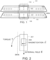
- a typical cochlear implant system may include an external transmitter housing 101 containing transmitting coils 102 and an external magnet 103 .
- the external magnet 103 has a conventional coin-shape and a north-south magnetic dipole that is perpendicular to the skin of the patient to produce external magnetic field lines 104 as shown.
- Implanted under the patient's skin is a corresponding receiver assembly 105 having similar receiving coils 106 and an implanted internal magnet 107 .
- the internal magnet 107 also has a coin-shape and a north-south magnetic dipole that is perpendicular to the skin of the patient to produce internal magnetic field lines 108 as shown.
- the internal receiver housing 105 is surgically implanted and fixed in place within the patient's body.
- the external transmitter housing 101 is placed in proper position over the skin covering the internal receiver assembly 105 and held in place by interaction between the internal magnetic field lines 108 and the external magnetic field lines 104 .
- Rf signals from the transmitter coils 102 couple data and/or power to the receiving coil 106 which is in communication with an implanted processor module (not shown).
- the external magnetic field B ⁇ from the MRI may create a torque T ⁇ on the internal magnet 202, which may displace the internal magnet 202 or the whole implant housing 201 out of proper position. Among other things, this may damage the adjacent tissue in the patient.
- the external magnetic field B ⁇ from the MRI may reduce or remove the magnetization m ⁇ of the implant magnet 202 so that it may no longer be strong enough to hold the external transmitter housing in proper position.
- the implant magnet 202 may also cause imaging artifacts in the MRI image, there may be induced voltages in the receiving coil, and hearing artifacts due to the interaction of the external magnetic field B ⁇ of the MRI with the implanted device. This is especially an issue with MRI field strengths exceeding 1.5 Tesla.
- the spherical magnet arrangement requires a relatively large magnet much larger than the thickness of the other components of the implant, thereby increasing the volume occupied by the implant. This in turn can create its own problems.
- some systems such as cochlear implants, are implanted between the skin and underlying bone.
- the "spherical bump" of the magnet housing therefore requires preparing a recess into the underlying bone. This is an additional step during implantation in such applications which can be very challenging or even impossible in case of very young children.
- WO 2010042463 A1 describes an external processor device for an implanted audio prosthesis.
- a low profile device housing attaches on the head of a patient user over an implanted receiver coil.
- a limited functionality processor within the device housing generates an implant data signal consisting of special non-representational audio data not characteristic of the nearby environment.
- a transmitter coil within the housing in communication with the processor transmits the implant data signal to the implanted receiver coil.
- inventions may also have at least one magnetic focus director within the housing adjacent to the first attachment magnet and transcutaneously directing the magnetic field to increase magnetic attraction force between the first and second attachment magnets by focusing the magnetic flux (i.e. locally increasing magnetic induction).
- the focus director may also be used to guide magnetic field lines away from magnetically sensitive components such as implanted sensors or ferrite-based components.
- the coil housing may be an implant coil housing for implantation under the skin of the patient and the signal coil would then be a receiver coil. There may also be an implant signal processor within the housing for processing the implant communication signal, and a magnetic switch within the coil housing and magnetically interacting with the first attachment magnet so as to affect operation of the signal processor as a function of magnetic orientation of the first attachment magnet. Or the coil housing may be an external coil housing for placement on the skin of the patient and the signal coil would then be a transmitter coil.
- the first attachment magnet may be adapted to rotate within the coil housing in response to an external magnetic field, and there may be a lubrication coating covering at least a portion of the first attachment magnet and reducing friction between the first attachment magnet and the coil housing to promote the rotation of the first attachment magnet.
- At least one of the attachment magnets may have a planar disc shape, a rectangular beam shape, a cylindrical beam shape, or a cut away disc shape.
- at least one of the attachment magnets may comprise a pair of complementary cylindrical attachment magnets, which optionally may further include a magnetic flux guide connecting the pair of complementary cylindrical attachment magnets. It is to be noted that the invention as claimed herein is limited to cases where the first attachment magnet has a planar disc shape or cut away disc shape and where the second attachment magnet has a magnetic dipole parallel to the plane of the external coil housing.
- the implantable system may be a cochlear implant system, a middle ear implant system, a vestibular implant system, or a laryngeal pacemaker implant system.
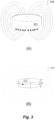
- FIG. 3A shows the magnetic field arrangement in typical existing implant attachment magnets.
- the attachment magnet 301 is disk-shaped (i.e., cylindrical) with the north-south magnetic dipole realized in the axial direction as is conventional producing magnetic field lines 302 as shown.
- Embodiments of the present invention change the direction of magnetization as shown in Figure 3B so that the north-south magnetic dipole is oriented across the diameter of the attachment magnet 301 parallel to (i.e., "in”) the plane of the coil housing, producing magnetic field lines 302 as shown.
- both the internal implant receiver attachment magnet and the external transmitter attachment magnet be magnetized with the same orientation in the plane of the coil housing (i.e., parallel to the skin). Then when the external coil housing is placed onto the patient's skin over the implant coil housing, the two attachment magnets turns around on their axis such that the north and south poles of one attachment magnet are positioned adjacent to south and north poles respectively of the other attachment magnet thereby maximizing the attractive magnetic force between the two.
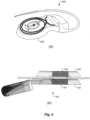
- Figure 4A shows an elevated perspective view and Figure 4B shows a side cross-sectional view of a cochlear implant 400 having a planar coil housing 402 that contains a signal coil for transcutaneous communication of an implant communication signal.
- a first attachment magnet 401 is located within the plane of the coil housing 402 and rotatable therein (e.g., a planar disk shape) has a magnetization direction with a magnetic dipole parallel to the plane of the coil housing 402 .
- the coil housing 402 may be made have a titanium case with the attachment magnet 401 located outside the titanium case, for example, embedded in a silicone coil assembly.
- the coil housing 402 may be a ceramic case where the attachment magnet 401 is hermetically encapsulated within the ceramic housing.
- the attachment magnet When a person wearing an implant with such an attachment magnet needs to undergo an MRI, they can enter the scanner room after the external components of the implant system have been removed. As the implant user is brought into the MR scanner, the attachment magnet may have a component of its magnetization which is perpendicular to the external magnetic field of the MR scanner. This will result in the attachment magnet turning around on its axis to align the magnetization direction of its magnetic dipole with the static field of the MR scanner.
- the attachment magnet of the implant can align with the static magnetic field of the MR system, there is no torque exerted by the static magnetic field of the MR on the attachment magnet/coil housing arrangement, nor is the magnetic force of the attachment magnet weakened. This is also the case when the attachment magnet cannot align completely with the static magnetic field of the MR scanner, but remains at an angle up to about 20° between the magnetic momentum of the implant magnet and the static magnetic field of the MR scanner. Since the torque is proportional to the sine of the angle, for example, the torque is reduced for a remaining angle of 20° to about 1/3 (66% reduction) of the torque when the attachment magnet remains fixed at the worst case angle of 90°.
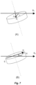
- the attachment magnet In situations where the rotational axis of the attachment magnet (i.e., its axis of symmetry) is exactly perpendicular to the static magnetic field of the MR system, the attachment magnet can turn around and can align its magnetic dipole m exactly with the static magnetic field B 0 without torque or demagnetization. But this is an ideal theoretical case, in most real situations the rotational axis of the attachment magnet is just close to but not exactly perpendicular to the static magnetic field, e.g., at an angle of 70° or 80° instead of 90°. This is shown in Fig. 7A . The attachment magnet will turn around on its axis and will try to align its magnetic dipole m with the surrounding magnetic field B 0 as best possible ( Fig. 7B ).
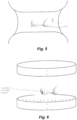
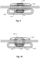
- Figure 8 A-B shows side and top view structural details of an embodiment wherein the coil housing 402 also contains a magnetic focus director 801 which surrounds some or all of the attachment magnet 401 .
- the magnetic focus director 801 is made of a soft ferromagnetic material that directs the magnetic field of the attachment magnet 401 through the skin to increase the magnetic attraction force with the other corresponding attachment magnet by focusing the magnetic flux (i.e. locally increasing magnetic induction).
- the focus director 801 may also be used to guide magnetic field lines away from magnetically sensitive components such as implanted sensors or ferrite-based components. In the specific embodiment shown in Fig.
- the magnetic focus director 801 has two generally rectangular opposing director pieces located on opposite sides of the attachment magnet 401 which then may have a defined equilibrium position in the absence of an external magnetic field such as an MRI field.
- the embodiment shown in Fig. 8 also shows a lubrication coating 802 made of polytetrafluoroethylene (PTFE) that covers at least a portion of the attachment magnet 401 and reduces the friction between the attachment magnet 401 and the coil housing 402 so as to promote the rotation of the attachment magnet 401 in response to external magnetic fields.
- PTFE polytetrafluoroethylene
- the attachment magnet may be fixed within the external component (e.g., transmitter coil housing) to prevent its rotation.
- the external attachment magnet may be fixed within the external component so that its magnetic axis is in a well-defined orientation when the external component is worn on the body. The position of the external component can then adjusted for the best magnet orientation to achieve the optimal (maximum) magnetic fixation of the external component.
- the attachment magnet may be encapsulated within the external component so that it can rotate on its axis like the attachment magnet in the implant.
- the implant attachment magnet may be not completely free to turn around, but may be limited to a certain maximum rotation angle.
- the implant attachment magnet may have a restoring force which positions it into a defined orientation as long as no external magnetic field is present.
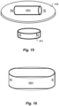
- Figure 9 shows an embodiment which includes a magnetic switch 901 within the coil housing 402 .
- the magnetic switch 901 magnetically interacts with the attachment magnet 401 so as to affect the operation of the implant signal processor as a function of the orientation of the attachment magnet 401 .
- the south pole of the attachment magnet 401 facing downwards (caudally) indicates that an external transmitter coil is located over the coil housing 402 so the implant signal processor is activated.
- reorienting the attachment magnet 401 so that the north magnetic pole faces downwards could trigger a different operating mode, e.g., a telemetry mode, recharging or programming mode, or for activating / deactivating electrodes.
- Such functionality would require that the external attachment magnet be fixed within its housing to prevent its rotation.
- Figure 10 shows an embodiment similar to the one in Fig. 8 which includes use of a horseshoe shaped attachment magnet 1001 .
- the attachment magnets have a magnetization axis that perpendicular to the rotational axis of the disk.
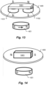
- Figure 11 shows a side view of another embodiment wherein the external coil housing 405 contains a pair of complementary cylindrical attachment magnets 1101 and 1102 with opposite magnetic polarities as shown which interact with the single cylindrical implant attachment magnet 401 which is free to rotate in the plane of the implant housing 405 to orient itself to magnetically interact with the external attachment magnets 1101 and 1102.
- Fig. 12 shows an elevated perspective view of some of the same structures.
- Fig. 13 shows a similar arrangement with an additional magnetic flux guide 1301 connecting the two external attachment magnets 1101 and 1102 .
- Non-spherical shaped magnets with a magnet field oriented in the plane of the coil housing basically the same advantages with regards to MR systems as with spherical magnet designs, with the main limitation being that the disk-shape attachment magnet design described above allows for rotation of the magnet in only one plane.
- the implant attachment magnet can align quite well with the static magnetic field both in closed MR scanners (with a horizontal main magnetic field) as well as is open MR scanners (with the main magnetic field in vertical direction).
- Attachment magnets according to embodiments of the present invention present a slim profile which is safe for MRI field strengths up to and beyond 3 Tesla without the need to surgically remove the implant magnet.
- the implant attachment magnet may be adapted to be temporarily removable by minor surgery from the implant coil housing if desired to reduce MRI artifacts.
- the present coil housing can have a flat bottom so that there is no need to drill a recess into the bone during implantation of the device. This makes such a magnet design especially well-suited for implantation in young children.
- embodiments can be equally effective where there is a relatively large magnet in the implanted part and a relatively small magnet in the external part, and vice versa. And due to the different magnetization direction, it is expected that the MR imaging artifact may be smaller compared to conventional implant magnets, for example, extending less in the medial direction.
- embodiments of the present invention have attractive forces on both poles, and the attraction is caused by two forces which apply at the two poles of each magnet.
- the result is that the shear force between the external attachment magnet and the implant attachment magnet is higher in the direction of the magnetization axis of the two magnets.
- By turning the external attachment magnet for optimal orientation over the implant e.g. vertical magnetic axis
- a better magnetic attachment of the external parts can be achieved.
- the external attachment magnet also stays in place over the implant attachment magnet with less lateral displacement even in response to small mechanical shocks.
- the present embodiments also have a better (shallower) force-over-distance diagram than two conventional magnets with axial magnetization. It may be advantageous if the attractive force does not vary greatly over the distance between the two attachment magnets.
- embodiments of the attachment magnet described here can align well with the static magnetic field in closed MR scanners only while such an implant magnet in axial orientation would only align with the static magnetic field in open scanners with vertical magnetic field.
- the torque exerted to the implant can remain relatively high when the implant magnet which has only one degree of freedom cannot align well enough with the external magnetic field.
Landscapes
- Health & Medical Sciences (AREA)
- Animal Behavior & Ethology (AREA)
- Life Sciences & Earth Sciences (AREA)
- Public Health (AREA)
- Veterinary Medicine (AREA)
- Engineering & Computer Science (AREA)
- Biomedical Technology (AREA)
- General Health & Medical Sciences (AREA)
- Nuclear Medicine, Radiotherapy & Molecular Imaging (AREA)
- Radiology & Medical Imaging (AREA)
- Otolaryngology (AREA)
- Heart & Thoracic Surgery (AREA)
- Cardiology (AREA)
- Physics & Mathematics (AREA)
- Electromagnetism (AREA)
- Pulmonology (AREA)
- Oral & Maxillofacial Surgery (AREA)
- Transplantation (AREA)
- Vascular Medicine (AREA)
- Acoustics & Sound (AREA)
- Prostheses (AREA)
- Magnetic Resonance Imaging Apparatus (AREA)
- Magnetic Treatment Devices (AREA)
Claims (1)
- Implantatsystem für einen empfangenden Patienten, wobei das Implantatsystem Folgendes umfasst:ein ebenes Implantatspulengehäuse (402) zur Implantation unter die Haut des Patienten, welches eine Empfängerspule für eine transkutane Kommunikation eines Implantat-Kommunikationssignals enthält und einen ersten Magneten (401) innerhalb der Ebene des Implantatspulengehäuses (402) enthält,ein ebenes externes Sendespulengehäuse (405) zur Anordnung auf der Haut des Patienten über dem Implantatspulengehäuse (402), wobei das externe Sendespulengehäuse (405) einen zweiten Befestigungsmagneten (404) innerhalb der Ebene des Sendespulengehäuses (405) umfasst;dadurch gekennzeichnet, dass der erste Befestigungsmagnet (401) in der genannten Ebene des Implantatspulengehäuses (402) drehbar ist, und der erste und der zweite Befestigungsmagnet (401, 404) einen zu der jeweiligen Ebene des Implantatspulengehäuses (402) bzw. des externen Sendespulengehäuses (405) parallelen magnetischen Dipol zur transkutanen magnetischen Wechselwirkung miteinander haben, was gestattet, eine magnetische Anziehungsverbindung zwischen ihnen zu bilden, bei der der magnetische Dipol des ersten Befestigungsmagneten (401) parallel zu der genannten Ebene des Implantatspulengehäuses (402) ist und der magnetische Dipol des zweiten Befestigungsmagneten (404) parallel zu der genannten Ebene des externen Sendespulengehäuses (405) ist, wobei der erste Befestigungsmagnet eine ebene Scheibenform oder eine ausgeschnittene Scheibenform hat.
Priority Applications (3)
| Application Number | Priority Date | Filing Date | Title |
|---|---|---|---|
| EP22177545.5A EP4074373B1 (de) | 2010-04-23 | 2011-04-21 | Mrt-sicherer plattenmagnet für implantate |
| PL16189856.4T PL3138605T5 (pl) | 2010-04-23 | 2011-04-21 | Bezpieczny dla obrazowania rezonansem magnetycznym magnes dyskowy dla implantów |
| EP19156900.3A EP3517169B1 (de) | 2010-04-23 | 2011-04-21 | Mrt-sicherer plattenmagnet für implantate |
Applications Claiming Priority (3)
| Application Number | Priority Date | Filing Date | Title |
|---|---|---|---|
| US32715810P | 2010-04-23 | 2010-04-23 | |
| EP11717431.8A EP2560730B1 (de) | 2010-04-23 | 2011-04-21 | Mri-sicherer plattenmagnet für implantate |
| PCT/US2011/033385 WO2011133747A1 (en) | 2010-04-23 | 2011-04-21 | Mri-safe disk magnet for implants |
Related Parent Applications (2)
| Application Number | Title | Priority Date | Filing Date |
|---|---|---|---|
| EP11717431.8A Division EP2560730B1 (de) | 2010-04-23 | 2011-04-21 | Mri-sicherer plattenmagnet für implantate |
| EP11717431.8A Division-Into EP2560730B1 (de) | 2010-04-23 | 2011-04-21 | Mri-sicherer plattenmagnet für implantate |
Related Child Applications (25)
| Application Number | Title | Priority Date | Filing Date |
|---|---|---|---|
| EP19156900.3A Division-Into EP3517169B1 (de) | 2010-04-23 | 2011-04-21 | Mrt-sicherer plattenmagnet für implantate |
| EP22177545.5A Division-Into EP4074373B1 (de) | 2010-04-23 | 2011-04-21 | Mrt-sicherer plattenmagnet für implantate |
| EP22177545.5A Division EP4074373B1 (de) | 2010-04-23 | 2011-04-21 | Mrt-sicherer plattenmagnet für implantate |
| EP19156900.3A Division EP3517169B1 (de) | 2010-04-23 | 2011-04-21 | Mrt-sicherer plattenmagnet für implantate |
| EP23199801.4 Division-Into | 2023-09-26 | ||
| EP23206150.7 Division-Into | 2023-10-26 | ||
| EP23212069.1 Division-Into | 2023-11-24 | ||
| EP23219919.0 Division-Into | 2023-12-22 | ||
| EP24153265.4 Division-Into | 2024-01-22 | ||
| EP24159141.1 Division-Into | 2024-02-22 | ||
| EP24165616.4 Division-Into | 2024-03-22 | ||
| EP24171701.6 Division-Into | 2024-04-22 | ||
| EP24177408.2 Division-Into | 2024-05-22 | ||
| EP24182993.6 Division-Into | 2024-06-19 | ||
| EP24189649.7 Division-Into | 2024-07-19 | ||
| EP24194843.9 Division-Into | 2024-08-16 | ||
| EP24200516.3 Division-Into | 2024-09-16 | ||
| EP24206955.7 Division-Into | 2024-10-16 | ||
| EP24213346.0 Division-Into | 2024-11-15 | ||
| EP24219868.7 Division-Into | 2024-12-13 | ||
| EP25151544.1 Division-Into | 2025-01-13 | ||
| EP25157781.3 Division-Into | 2025-02-13 | ||
| EP25163553.8 Division-Into | 2025-03-13 | ||
| EP25170428.4 Division-Into | 2025-04-14 | ||
| EP25176425.4 Division-Into | 2025-05-14 |
Publications (3)
| Publication Number | Publication Date |
|---|---|
| EP3138605A1 EP3138605A1 (de) | 2017-03-08 |
| EP3138605B1 EP3138605B1 (de) | 2019-04-10 |
| EP3138605B2 true EP3138605B2 (de) | 2025-07-09 |
Family
ID=44260168
Family Applications (4)
| Application Number | Title | Priority Date | Filing Date |
|---|---|---|---|
| EP16189856.4A Active EP3138605B2 (de) | 2010-04-23 | 2011-04-21 | Mrt-sicherer plattenmagnet für implantate |
| EP19156900.3A Active EP3517169B1 (de) | 2010-04-23 | 2011-04-21 | Mrt-sicherer plattenmagnet für implantate |
| EP11717431.8A Active EP2560730B1 (de) | 2010-04-23 | 2011-04-21 | Mri-sicherer plattenmagnet für implantate |
| EP22177545.5A Active EP4074373B1 (de) | 2010-04-23 | 2011-04-21 | Mrt-sicherer plattenmagnet für implantate |
Family Applications After (3)
| Application Number | Title | Priority Date | Filing Date |
|---|---|---|---|
| EP19156900.3A Active EP3517169B1 (de) | 2010-04-23 | 2011-04-21 | Mrt-sicherer plattenmagnet für implantate |
| EP11717431.8A Active EP2560730B1 (de) | 2010-04-23 | 2011-04-21 | Mri-sicherer plattenmagnet für implantate |
| EP22177545.5A Active EP4074373B1 (de) | 2010-04-23 | 2011-04-21 | Mrt-sicherer plattenmagnet für implantate |
Country Status (9)
| Country | Link |
|---|---|
| US (1) | US8634909B2 (de) |
| EP (4) | EP3138605B2 (de) |
| KR (1) | KR101743793B1 (de) |
| CN (1) | CN102905756B (de) |
| AU (1) | AU2011242708B2 (de) |
| DK (1) | DK3138605T4 (de) |
| ES (4) | ES2967007T3 (de) |
| PL (4) | PL4074373T3 (de) |
| WO (1) | WO2011133747A1 (de) |
Families Citing this family (56)
| Publication number | Priority date | Publication date | Assignee | Title |
|---|---|---|---|---|
| AU2003233025B2 (en) | 2002-04-01 | 2008-04-10 | Med-El Elektromedizinische Geraete Gmbh | Reducing effect of magnetic and electromagnetic fields on an implants magnet and/or electronic |
| AU2003901696A0 (en) | 2003-04-09 | 2003-05-01 | Cochlear Limited | Implant magnet system |
| US8811643B2 (en) | 2003-05-08 | 2014-08-19 | Advanced Bionics | Integrated cochlear implant headpiece |
| SE531177C2 (sv) | 2007-05-24 | 2009-01-13 | Cochlear Ltd | Distans för implantat |
| EP3138605B2 (de) | 2010-04-23 | 2025-07-09 | MED-EL Elektromedizinische Geräte GmbH | Mrt-sicherer plattenmagnet für implantate |
| AU2012358871B2 (en) * | 2011-12-22 | 2015-06-18 | Med-El Elektromedizinische Geraete Gmbh | Magnet arrangement for bone conduction hearing implant |
| CN104302224B (zh) * | 2012-05-07 | 2016-08-24 | 奥林巴斯株式会社 | 引导装置 |
| ES2645986T3 (es) * | 2012-07-03 | 2017-12-11 | Med-El Elektromedizinische Geraete Gmbh | Imán para implantar sin riesgo para la IRM con magnetización angular |
| CN104885481B (zh) | 2012-07-09 | 2018-05-29 | Med-El电气医疗器械有限公司 | 电磁骨骼传导听力设备 |
| US9427566B2 (en) | 2013-08-14 | 2016-08-30 | Syntilla Medical LLC | Implantable neurostimulation lead for head pain |
| US9042991B2 (en) | 2013-08-14 | 2015-05-26 | Syntilla Medical LLC | Implantable head mounted neurostimulation system for head pain |
| US9839777B2 (en) | 2013-08-14 | 2017-12-12 | Syntilla Medical LLC | Implantable neurostimulation lead for head pain |
| US9498635B2 (en) | 2013-10-16 | 2016-11-22 | Syntilla Medical LLC | Implantable head located radiofrequency coupled neurostimulation system for head pain |
| US10258805B2 (en) | 2013-10-23 | 2019-04-16 | Syntilla Medical, Llc | Surgical method for implantable head mounted neurostimulation system for head pain |
| US10960215B2 (en) | 2013-10-23 | 2021-03-30 | Nuxcel, Inc. | Low profile head-located neurostimulator and method of fabrication |
| EP3060297B1 (de) * | 2013-10-24 | 2019-08-14 | MED-EL Elektromedizinische Geräte GmbH | Schätzung der hautdicke über einem implantierten magneten |
| US9800982B2 (en) | 2014-06-18 | 2017-10-24 | Cochlear Limited | Electromagnetic transducer with expanded magnetic flux functionality |
| US10091594B2 (en) * | 2014-07-29 | 2018-10-02 | Cochlear Limited | Bone conduction magnetic retention system |
| US9744056B2 (en) | 2014-08-06 | 2017-08-29 | Rehabilitation Institute Of Chicago | Magnetic electrical connector for assistive devices |
| US20180110985A1 (en) | 2015-05-28 | 2018-04-26 | Jeryle L. Walter | Cochlear implants having mri-compatible magnet apparatus and associated methods |
| US10130807B2 (en) | 2015-06-12 | 2018-11-20 | Cochlear Limited | Magnet management MRI compatibility |
| US20160381473A1 (en) * | 2015-06-26 | 2016-12-29 | Johan Gustafsson | Magnetic retention device |
| EP3314912B1 (de) * | 2015-06-26 | 2023-11-22 | Cochlear Limited | Magnetische haltevorrichtung |
| AU2016318802A1 (en) * | 2015-09-09 | 2018-03-22 | Med-El Elektromedizinische Geraete Gmbh | Fixation of a removable magnet or a similar element in an elastic implant material |
| US10917730B2 (en) | 2015-09-14 | 2021-02-09 | Cochlear Limited | Retention magnet system for medical device |
| US9980066B2 (en) | 2015-09-18 | 2018-05-22 | Med-El Elektromedizinische Geraete Gmbh | Bone conduction transducer system with adjustable retention force |
| US10806936B2 (en) | 2015-11-20 | 2020-10-20 | Advanced Bionics Ag | Cochlear implants and magnets for use with same |
| EP3389766B1 (de) * | 2015-12-18 | 2019-11-20 | Advanced Bionics AG | Cochlea-implantate mit mrt-kompatibler magnetvorrichtung und zugehörige verfahren |
| WO2017105511A1 (en) | 2015-12-18 | 2017-06-22 | Advanced Bionics Ag | Cochlear implants having mri-compatible magnet apparatus |
| US9717917B2 (en) | 2016-01-06 | 2017-08-01 | Syntilla Medical LLC | Charging system incorporating independent charging and communication with multiple implanted devices |
| US10129667B2 (en) * | 2016-02-26 | 2018-11-13 | Cochlear Limited | Multi-pole magnetic coupling for bone conduction device |
| US11426593B2 (en) | 2016-03-29 | 2022-08-30 | Med-El Elektromedizinische Geraete Gmbh | Cochlear implant with clippable magnet |
| US10576276B2 (en) | 2016-04-29 | 2020-03-03 | Cochlear Limited | Implanted magnet management in the face of external magnetic fields |
| US10646718B2 (en) | 2016-11-15 | 2020-05-12 | Advanced Bionics Ag | Cochlear implants and magnets for use with same |
| US10674287B2 (en) | 2016-11-23 | 2020-06-02 | Cochlear Limited | Magnet placement and antenna placement of an implant |
| US11595768B2 (en) | 2016-12-02 | 2023-02-28 | Cochlear Limited | Retention force increasing components |
| WO2018190813A1 (en) | 2017-04-11 | 2018-10-18 | Advanced Bionics Ag | Cochlear implants with retrofit magnets |
| CN110583029B (zh) * | 2017-04-24 | 2021-05-18 | Med-El电气医疗器械有限公司 | Mri安全性和力被优化的植入物磁体系统 |
| CN110545880B (zh) | 2017-04-25 | 2023-09-01 | 领先仿生公司 | 具有抗冲击的与mri兼容的磁体设备的耳蜗植入物 |
| CN110650769B (zh) | 2017-05-22 | 2023-12-22 | 领先仿生公司 | 颗粒对准方法和颗粒对准指示套件 |
| US10646712B2 (en) | 2017-09-13 | 2020-05-12 | Advanced Bionics Ag | Cochlear implants having MRI-compatible magnet apparatus |
| WO2019083540A1 (en) | 2017-10-26 | 2019-05-02 | Advanced Bionics Ag | EXTERNAL MODULES AND IMPLANTABLE COCHLEAR STIMULATION SYSTEMS COMPRISING THE SAME |
| CN119386379A (zh) | 2018-02-15 | 2025-02-07 | 领先仿生公司 | 头戴装置和包括其的可植入耳蜗刺激系统 |
| WO2019183586A1 (en) * | 2018-03-23 | 2019-09-26 | The Alfred E. Mann Foundation For Scientific Research | Skin patches for sensing or affecting a body parameter |
| WO2020092185A1 (en) * | 2018-10-29 | 2020-05-07 | Med-El Elektromedizinische Geraete Gmbh | Cylindrical implant magnet optimized for mri |
| WO2020136601A1 (en) * | 2018-12-27 | 2020-07-02 | Cochlear Limited | Advanced implanted magnet management in the face of external magnetic fields |
| WO2020212849A1 (en) * | 2019-04-15 | 2020-10-22 | Cochlear Limited | Magnet management mri compatibility by shape |
| WO2021059163A1 (en) * | 2019-09-27 | 2021-04-01 | Cochlear Limited | Multipole magnet for medical implant system |
| CN113126012B (zh) * | 2019-12-30 | 2025-04-11 | 创领心律管理医疗器械(上海)有限公司 | 有源植入式医疗器械及其磁感应机构 |
| CN115361995A (zh) | 2020-03-31 | 2022-11-18 | 领先仿生公司 | 耳机和包括该耳机的可植入耳蜗刺激系统 |
| US11616397B2 (en) * | 2020-08-12 | 2023-03-28 | Medtronic, Inc. | Magnetic alignment of transcutaneous energy transfer coils |
| EA202192120A1 (ru) * | 2020-09-02 | 2022-03-31 | Мед-Эл Электромедицинише Герете Гмбх | Удерживающие магниты и магнитная система для имплантируемых систем, оптимизированных для мрт |
| AU2021225130B2 (en) * | 2020-09-09 | 2024-01-18 | Med-El Elektromedizinische Geraete Gmbh | Holding Magnets and Magnet System for Implantable Systems Optimized for MRI |
| CN112546435B (zh) * | 2020-12-14 | 2025-07-01 | 浙江诺尔康神经电子科技股份有限公司 | 一种带开关的人工耳蜗磁性装置 |
| US12440668B2 (en) | 2021-10-12 | 2025-10-14 | Advanced Bionics Ag | Cochlear implants having MRI-compatible magnet apparatus and associated systems and methods |
| CN115814273A (zh) * | 2022-12-01 | 2023-03-21 | 上海力声特医学科技有限公司 | 一种植入式磁铁及制备方法 |
Citations (2)
| Publication number | Priority date | Publication date | Assignee | Title |
|---|---|---|---|---|
| US6761681B2 (en) † | 2001-08-14 | 2004-07-13 | Phonak Ag | Percutaneous or transcutaneous access into the body |
| US7266208B2 (en) † | 2002-06-21 | 2007-09-04 | Mxm | Auditory aid device for the rehabilitation of patients suffering from partial neurosensory hearing loss |
Family Cites Families (35)
| Publication number | Priority date | Publication date | Assignee | Title |
|---|---|---|---|---|
| US3573812A (en) | 1967-11-06 | 1971-04-06 | Miniature Elect Components | Electromagnetic indicator |
| US3527220A (en) | 1968-06-28 | 1970-09-08 | Fairchild Hiller Corp | Implantable drug administrator |
| US3608088A (en) | 1969-04-17 | 1971-09-28 | Univ Minnesota | Implantable blood pump |
| US3766928A (en) | 1972-03-24 | 1973-10-23 | American Optical Corp | Pacer with magnetic coupling means for external rate adjustment |
| US4352960A (en) | 1980-09-30 | 1982-10-05 | Baptist Medical Center Of Oklahoma, Inc. | Magnetic transcutaneous mount for external device of an associated implant |
| US4615691A (en) | 1983-12-08 | 1986-10-07 | Salomon Hakim | Surgically-implantable stepping motor |
| US4994019A (en) | 1989-07-28 | 1991-02-19 | Micro-Magnetics, Inc. | Magnetic occluding device |
| WO1992022107A1 (en) | 1991-06-06 | 1992-12-10 | Cochlear Pty. Limited | Percutaneous connector |
| US5554096A (en) | 1993-07-01 | 1996-09-10 | Symphonix | Implantable electromagnetic hearing transducer |
| US5762599A (en) | 1994-05-02 | 1998-06-09 | Influence Medical Technologies, Ltd. | Magnetically-coupled implantable medical devices |
| US6141591A (en) | 1996-03-06 | 2000-10-31 | Advanced Bionics Corporation | Magnetless implantable stimulator and external transmitter and implant tools for aligning same |
| US5877664A (en) | 1996-05-08 | 1999-03-02 | Jackson, Jr.; John T. | Magnetic proximity switch system |
| US6178079B1 (en) | 1996-05-16 | 2001-01-23 | Pacesetter, Inc. | Magnetic annunciator |
| DE69839051T2 (de) | 1997-03-07 | 2009-01-15 | Disc-O-Tech Medical Technologies, Ltd. | Systeme zur perkutanen knochen und wirbelstabilisirung,befestigung und reparatur |
| DE19840989A1 (de) | 1997-09-09 | 1999-03-18 | Tokyo Electron Ltd | Reinigungsverfahren und Reinigungsgerät |
| US6348070B1 (en) | 1998-04-17 | 2002-02-19 | Med-El Elektromedizinische Gerate Ges.M.B.H | Magnetic-interference-free surgical prostheses |
| US6077299A (en) | 1998-06-22 | 2000-06-20 | Eyetronic, Llc | Non-invasively adjustable valve implant for the drainage of aqueous humor in glaucoma |
| US6178353B1 (en) | 1998-07-27 | 2001-01-23 | Advanced Bionics Corporation | Laminated magnet keeper for implant device |
| US6217508B1 (en) | 1998-08-14 | 2001-04-17 | Symphonix Devices, Inc. | Ultrasonic hearing system |
| US6292678B1 (en) | 1999-05-13 | 2001-09-18 | Stereotaxis, Inc. | Method of magnetically navigating medical devices with magnetic fields and gradients, and medical devices adapted therefor |
| US6358281B1 (en) | 1999-11-29 | 2002-03-19 | Epic Biosonics Inc. | Totally implantable cochlear prosthesis |
| US7266209B1 (en) | 2000-01-05 | 2007-09-04 | David William House | Cochlear implants with a stimulus in the human ultrasonic range and method for stimulating a cochlea |
| US6506987B1 (en) | 2001-07-19 | 2003-01-14 | Randy Woods | Magnetic switch |
| AU2003233025B2 (en) * | 2002-04-01 | 2008-04-10 | Med-El Elektromedizinische Geraete Gmbh | Reducing effect of magnetic and electromagnetic fields on an implants magnet and/or electronic |
| AUPS192202A0 (en) | 2002-04-23 | 2002-05-30 | Cochlear Limited | Mri-compatible cochlear implant |
| CN1583193A (zh) * | 2004-05-27 | 2005-02-23 | 杭州康尔医药科技有限公司 | 一种改进型低频旋转强恒磁场治疗装置 |
| KR100735078B1 (ko) | 2006-07-21 | 2007-07-03 | (주)머티리얼솔루션테크놀로지 | 인공와우 |
| DE602008001247D1 (de) | 2007-03-07 | 2010-06-24 | Med El Elektromed Geraete Gmbh | Implantierbare vorrichtung mit entfernbarem magneten |
| US8133215B2 (en) | 2007-08-13 | 2012-03-13 | Cochlear Limited | Independently-manufactured drug delivery module and corresponding receptacle in an implantable medical device |
| FR2931076B1 (fr) | 2008-05-15 | 2010-06-25 | Neurelec | Dispositif implantable sous-cutane |
| AU2009256310B2 (en) * | 2008-06-03 | 2012-05-03 | Med-El Elektromedizinische Geraete Gmbh | Conductive coating of implants with inductive link |
| WO2010042463A1 (en) * | 2008-10-07 | 2010-04-15 | Med-El Elektromedizinische Geraete Gmbh | Cochlear implant sound processor for sleeping with tinnitus suppression and alarm function |
| EP2355889B1 (de) | 2008-11-12 | 2013-12-18 | Advanced Bionics, LLC | Cochleaimplantatsysteme mit magnetflussumleitung |
| EP3138605B2 (de) | 2010-04-23 | 2025-07-09 | MED-EL Elektromedizinische Geräte GmbH | Mrt-sicherer plattenmagnet für implantate |
| CN110545880B (zh) | 2017-04-25 | 2023-09-01 | 领先仿生公司 | 具有抗冲击的与mri兼容的磁体设备的耳蜗植入物 |
-
2011
- 2011-04-21 EP EP16189856.4A patent/EP3138605B2/de active Active
- 2011-04-21 ES ES22177545T patent/ES2967007T3/es active Active
- 2011-04-21 US US13/091,352 patent/US8634909B2/en active Active
- 2011-04-21 PL PL22177545.5T patent/PL4074373T3/pl unknown
- 2011-04-21 EP EP19156900.3A patent/EP3517169B1/de active Active
- 2011-04-21 PL PL11717431T patent/PL2560730T3/pl unknown
- 2011-04-21 WO PCT/US2011/033385 patent/WO2011133747A1/en not_active Ceased
- 2011-04-21 AU AU2011242708A patent/AU2011242708B2/en active Active
- 2011-04-21 ES ES16189856T patent/ES2733540T5/es active Active
- 2011-04-21 PL PL16189856.4T patent/PL3138605T5/pl unknown
- 2011-04-21 PL PL19156900.3T patent/PL3517169T3/pl unknown
- 2011-04-21 CN CN201180020521.8A patent/CN102905756B/zh active Active
- 2011-04-21 ES ES19156900T patent/ES2926718T3/es active Active
- 2011-04-21 KR KR1020127030615A patent/KR101743793B1/ko active Active
- 2011-04-21 ES ES11717431.8T patent/ES2610358T3/es active Active
- 2011-04-21 EP EP11717431.8A patent/EP2560730B1/de active Active
- 2011-04-21 DK DK16189856.4T patent/DK3138605T4/da active
- 2011-04-21 EP EP22177545.5A patent/EP4074373B1/de active Active
Patent Citations (2)
| Publication number | Priority date | Publication date | Assignee | Title |
|---|---|---|---|---|
| US6761681B2 (en) † | 2001-08-14 | 2004-07-13 | Phonak Ag | Percutaneous or transcutaneous access into the body |
| US7266208B2 (en) † | 2002-06-21 | 2007-09-04 | Mxm | Auditory aid device for the rehabilitation of patients suffering from partial neurosensory hearing loss |
Also Published As
| Publication number | Publication date |
|---|---|
| ES2926718T3 (es) | 2022-10-27 |
| US20110264172A1 (en) | 2011-10-27 |
| CN102905756A (zh) | 2013-01-30 |
| EP4074373B1 (de) | 2023-09-27 |
| ES2733540T5 (en) | 2025-11-27 |
| PL4074373T3 (pl) | 2024-03-04 |
| EP3517169A1 (de) | 2019-07-31 |
| WO2011133747A1 (en) | 2011-10-27 |
| US8634909B2 (en) | 2014-01-21 |
| AU2011242708B2 (en) | 2013-09-05 |
| DK3138605T3 (da) | 2019-07-15 |
| EP2560730B1 (de) | 2016-11-02 |
| EP4074373A1 (de) | 2022-10-19 |
| PL2560730T3 (pl) | 2017-04-28 |
| ES2967007T3 (es) | 2024-04-25 |
| PL3138605T3 (pl) | 2019-10-31 |
| KR20130052574A (ko) | 2013-05-22 |
| AU2011242708A1 (en) | 2012-10-25 |
| PL3138605T5 (pl) | 2025-11-03 |
| ES2733540T3 (es) | 2019-11-29 |
| CN102905756B (zh) | 2015-04-01 |
| EP3517169B1 (de) | 2022-06-08 |
| DK3138605T4 (da) | 2025-09-29 |
| EP3138605A1 (de) | 2017-03-08 |
| ES2610358T3 (es) | 2017-04-27 |
| KR101743793B1 (ko) | 2017-06-05 |
| EP3138605B1 (de) | 2019-04-10 |
| PL3517169T3 (pl) | 2022-11-21 |
| EP4074373C0 (de) | 2023-09-27 |
| EP2560730A1 (de) | 2013-02-27 |
Similar Documents
| Publication | Publication Date | Title |
|---|---|---|
| EP3138605B2 (de) | Mrt-sicherer plattenmagnet für implantate | |
| EP2869890B1 (de) | Mrt-sicherer implantatmagnet mit winkelmagnetisierung | |
| US11660447B2 (en) | MRI-safe and force-optimized implantable ring magnet system with an enhanced inductive link | |
| US20120296155A1 (en) | Magnetic Attachment Arrangement for Implantable Device | |
| EP2869892B1 (de) | Symmetrische magnetanordnung für medizinische implantate | |
| CA2768490C (en) | Magnetic attachment arrangement for implantable device | |
| US11938319B2 (en) | Cylindrical implant magnet optimized for MRI | |
| EP3436141B1 (de) | Cochleaimplantat mit klippmagnet | |
| CN114191719B (zh) | 用于针对mri优化的可植入系统的保持磁体和磁体系统 | |
| EA045972B1 (ru) | Удерживающие магниты и магнитная система для имплантируемых систем, оптимизированных для мрт |
Legal Events
| Date | Code | Title | Description |
|---|---|---|---|
| PUAI | Public reference made under article 153(3) epc to a published international application that has entered the european phase |
Free format text: ORIGINAL CODE: 0009012 |
|
| STAA | Information on the status of an ep patent application or granted ep patent |
Free format text: STATUS: THE APPLICATION HAS BEEN PUBLISHED |
|
| AC | Divisional application: reference to earlier application |
Ref document number: 2560730 Country of ref document: EP Kind code of ref document: P |
|
| AK | Designated contracting states |
Kind code of ref document: A1 Designated state(s): AL AT BE BG CH CY CZ DE DK EE ES FI FR GB GR HR HU IE IS IT LI LT LU LV MC MK MT NL NO PL PT RO RS SE SI SK SM TR |
|
| RIN1 | Information on inventor provided before grant (corrected) |
Inventor name: JAMNIG, BERNHARD Inventor name: ZIMMERLING, MARTIN |
|
| STAA | Information on the status of an ep patent application or granted ep patent |
Free format text: STATUS: REQUEST FOR EXAMINATION WAS MADE |
|
| 17P | Request for examination filed |
Effective date: 20170908 |
|
| RBV | Designated contracting states (corrected) |
Designated state(s): AL AT BE BG CH CY CZ DE DK EE ES FI FR GB GR HR HU IE IS IT LI LT LU LV MC MK MT NL NO PL PT RO RS SE SI SK SM TR |
|
| RAP1 | Party data changed (applicant data changed or rights of an application transferred) |
Owner name: MED-EL ELEKTROMEDIZINISCHE GERAETE GMBH |
|
| GRAP | Despatch of communication of intention to grant a patent |
Free format text: ORIGINAL CODE: EPIDOSNIGR1 |
|
| STAA | Information on the status of an ep patent application or granted ep patent |
Free format text: STATUS: GRANT OF PATENT IS INTENDED |
|
| GRAJ | Information related to disapproval of communication of intention to grant by the applicant or resumption of examination proceedings by the epo deleted |
Free format text: ORIGINAL CODE: EPIDOSDIGR1 |
|
| STAA | Information on the status of an ep patent application or granted ep patent |
Free format text: STATUS: REQUEST FOR EXAMINATION WAS MADE |
|
| RIC1 | Information provided on ipc code assigned before grant |
Ipc: A61N 1/37 20060101ALN20190114BHEP Ipc: A61N 1/372 20060101ALN20190114BHEP Ipc: A61N 1/36 20060101AFI20190114BHEP |
|
| INTG | Intention to grant announced |
Effective date: 20190130 |
|
| GRAR | Information related to intention to grant a patent recorded |
Free format text: ORIGINAL CODE: EPIDOSNIGR71 |
|
| GRAS | Grant fee paid |
Free format text: ORIGINAL CODE: EPIDOSNIGR3 |
|
| STAA | Information on the status of an ep patent application or granted ep patent |
Free format text: STATUS: GRANT OF PATENT IS INTENDED |
|
| GRAA | (expected) grant |
Free format text: ORIGINAL CODE: 0009210 |
|
| STAA | Information on the status of an ep patent application or granted ep patent |
Free format text: STATUS: THE PATENT HAS BEEN GRANTED |
|
| INTC | Intention to grant announced (deleted) | ||
| RIC1 | Information provided on ipc code assigned before grant |
Ipc: A61N 1/372 20060101ALN20190205BHEP Ipc: A61N 1/36 20060101AFI20190205BHEP Ipc: A61N 1/37 20060101ALN20190205BHEP |
|
| AC | Divisional application: reference to earlier application |
Ref document number: 2560730 Country of ref document: EP Kind code of ref document: P |
|
| AK | Designated contracting states |
Kind code of ref document: B1 Designated state(s): AL AT BE BG CH CY CZ DE DK EE ES FI FR GB GR HR HU IE IS IT LI LT LU LV MC MK MT NL NO PL PT RO RS SE SI SK SM TR |
|
| INTG | Intention to grant announced |
Effective date: 20190304 |
|
| REG | Reference to a national code |
Ref country code: GB Ref legal event code: FG4D |
|
| REG | Reference to a national code |
Ref country code: AT Ref legal event code: REF Ref document number: 1117871 Country of ref document: AT Kind code of ref document: T Effective date: 20190415 Ref country code: CH Ref legal event code: EP |
|
| REG | Reference to a national code |
Ref country code: IE Ref legal event code: FG4D |
|
| REG | Reference to a national code |
Ref country code: DE Ref legal event code: R096 Ref document number: 602011058065 Country of ref document: DE |
|
| REG | Reference to a national code |
Ref country code: NL Ref legal event code: FP |
|
| REG | Reference to a national code |
Ref country code: SE Ref legal event code: TRGR |
|
| REG | Reference to a national code |
Ref country code: NO Ref legal event code: T2 Effective date: 20190410 |
|
| REG | Reference to a national code |
Ref country code: DK Ref legal event code: T3 Effective date: 20190709 |
|
| REG | Reference to a national code |
Ref country code: LT Ref legal event code: MG4D |
|
| REG | Reference to a national code |
Ref country code: CH Ref legal event code: NV Representative=s name: E. BLUM AND CO. AG PATENT- UND MARKENANWAELTE , CH |
|
| PG25 | Lapsed in a contracting state [announced via postgrant information from national office to epo] |
Ref country code: LT Free format text: LAPSE BECAUSE OF FAILURE TO SUBMIT A TRANSLATION OF THE DESCRIPTION OR TO PAY THE FEE WITHIN THE PRESCRIBED TIME-LIMIT Effective date: 20190410 Ref country code: AL Free format text: LAPSE BECAUSE OF FAILURE TO SUBMIT A TRANSLATION OF THE DESCRIPTION OR TO PAY THE FEE WITHIN THE PRESCRIBED TIME-LIMIT Effective date: 20190410 Ref country code: FI Free format text: LAPSE BECAUSE OF FAILURE TO SUBMIT A TRANSLATION OF THE DESCRIPTION OR TO PAY THE FEE WITHIN THE PRESCRIBED TIME-LIMIT Effective date: 20190410 Ref country code: PT Free format text: LAPSE BECAUSE OF FAILURE TO SUBMIT A TRANSLATION OF THE DESCRIPTION OR TO PAY THE FEE WITHIN THE PRESCRIBED TIME-LIMIT Effective date: 20190910 Ref country code: HR Free format text: LAPSE BECAUSE OF FAILURE TO SUBMIT A TRANSLATION OF THE DESCRIPTION OR TO PAY THE FEE WITHIN THE PRESCRIBED TIME-LIMIT Effective date: 20190410 |
|
| PG25 | Lapsed in a contracting state [announced via postgrant information from national office to epo] |
Ref country code: LV Free format text: LAPSE BECAUSE OF FAILURE TO SUBMIT A TRANSLATION OF THE DESCRIPTION OR TO PAY THE FEE WITHIN THE PRESCRIBED TIME-LIMIT Effective date: 20190410 Ref country code: GR Free format text: LAPSE BECAUSE OF FAILURE TO SUBMIT A TRANSLATION OF THE DESCRIPTION OR TO PAY THE FEE WITHIN THE PRESCRIBED TIME-LIMIT Effective date: 20190711 Ref country code: RS Free format text: LAPSE BECAUSE OF FAILURE TO SUBMIT A TRANSLATION OF THE DESCRIPTION OR TO PAY THE FEE WITHIN THE PRESCRIBED TIME-LIMIT Effective date: 20190410 Ref country code: BG Free format text: LAPSE BECAUSE OF FAILURE TO SUBMIT A TRANSLATION OF THE DESCRIPTION OR TO PAY THE FEE WITHIN THE PRESCRIBED TIME-LIMIT Effective date: 20190710 |
|
| REG | Reference to a national code |
Ref country code: ES Ref legal event code: FG2A Ref document number: 2733540 Country of ref document: ES Kind code of ref document: T3 Effective date: 20191129 |
|
| PG25 | Lapsed in a contracting state [announced via postgrant information from national office to epo] |
Ref country code: LU Free format text: LAPSE BECAUSE OF NON-PAYMENT OF DUE FEES Effective date: 20190421 Ref country code: IS Free format text: LAPSE BECAUSE OF FAILURE TO SUBMIT A TRANSLATION OF THE DESCRIPTION OR TO PAY THE FEE WITHIN THE PRESCRIBED TIME-LIMIT Effective date: 20190810 |
|
| REG | Reference to a national code |
Ref country code: DE Ref legal event code: R026 Ref document number: 602011058065 Country of ref document: DE |
|
| PLBI | Opposition filed |
Free format text: ORIGINAL CODE: 0009260 |
|
| PLAX | Notice of opposition and request to file observation + time limit sent |
Free format text: ORIGINAL CODE: EPIDOSNOBS2 |
|
| PG25 | Lapsed in a contracting state [announced via postgrant information from national office to epo] |
Ref country code: MC Free format text: LAPSE BECAUSE OF FAILURE TO SUBMIT A TRANSLATION OF THE DESCRIPTION OR TO PAY THE FEE WITHIN THE PRESCRIBED TIME-LIMIT Effective date: 20190410 Ref country code: SK Free format text: LAPSE BECAUSE OF FAILURE TO SUBMIT A TRANSLATION OF THE DESCRIPTION OR TO PAY THE FEE WITHIN THE PRESCRIBED TIME-LIMIT Effective date: 20190410 Ref country code: CZ Free format text: LAPSE BECAUSE OF FAILURE TO SUBMIT A TRANSLATION OF THE DESCRIPTION OR TO PAY THE FEE WITHIN THE PRESCRIBED TIME-LIMIT Effective date: 20190410 Ref country code: EE Free format text: LAPSE BECAUSE OF FAILURE TO SUBMIT A TRANSLATION OF THE DESCRIPTION OR TO PAY THE FEE WITHIN THE PRESCRIBED TIME-LIMIT Effective date: 20190410 Ref country code: RO Free format text: LAPSE BECAUSE OF FAILURE TO SUBMIT A TRANSLATION OF THE DESCRIPTION OR TO PAY THE FEE WITHIN THE PRESCRIBED TIME-LIMIT Effective date: 20190410 |
|
| 26 | Opposition filed |
Opponent name: ADVANCED BIONICS AG Effective date: 20200108 |
|
| PG25 | Lapsed in a contracting state [announced via postgrant information from national office to epo] |
Ref country code: SM Free format text: LAPSE BECAUSE OF FAILURE TO SUBMIT A TRANSLATION OF THE DESCRIPTION OR TO PAY THE FEE WITHIN THE PRESCRIBED TIME-LIMIT Effective date: 20190410 |
|
| PG25 | Lapsed in a contracting state [announced via postgrant information from national office to epo] |
Ref country code: TR Free format text: LAPSE BECAUSE OF FAILURE TO SUBMIT A TRANSLATION OF THE DESCRIPTION OR TO PAY THE FEE WITHIN THE PRESCRIBED TIME-LIMIT Effective date: 20190410 |
|
| PG25 | Lapsed in a contracting state [announced via postgrant information from national office to epo] |
Ref country code: IE Free format text: LAPSE BECAUSE OF NON-PAYMENT OF DUE FEES Effective date: 20190421 |
|
| PG25 | Lapsed in a contracting state [announced via postgrant information from national office to epo] |
Ref country code: SI Free format text: LAPSE BECAUSE OF FAILURE TO SUBMIT A TRANSLATION OF THE DESCRIPTION OR TO PAY THE FEE WITHIN THE PRESCRIBED TIME-LIMIT Effective date: 20190410 |
|
| PLBB | Reply of patent proprietor to notice(s) of opposition received |
Free format text: ORIGINAL CODE: EPIDOSNOBS3 |
|
| APBM | Appeal reference recorded |
Free format text: ORIGINAL CODE: EPIDOSNREFNO |
|
| APBP | Date of receipt of notice of appeal recorded |
Free format text: ORIGINAL CODE: EPIDOSNNOA2O |
|
| PG25 | Lapsed in a contracting state [announced via postgrant information from national office to epo] |
Ref country code: CY Free format text: LAPSE BECAUSE OF FAILURE TO SUBMIT A TRANSLATION OF THE DESCRIPTION OR TO PAY THE FEE WITHIN THE PRESCRIBED TIME-LIMIT Effective date: 20190410 |
|
| APAH | Appeal reference modified |
Free format text: ORIGINAL CODE: EPIDOSCREFNO |
|
| PG25 | Lapsed in a contracting state [announced via postgrant information from national office to epo] |
Ref country code: MT Free format text: LAPSE BECAUSE OF FAILURE TO SUBMIT A TRANSLATION OF THE DESCRIPTION OR TO PAY THE FEE WITHIN THE PRESCRIBED TIME-LIMIT Effective date: 20190410 Ref country code: HU Free format text: LAPSE BECAUSE OF FAILURE TO SUBMIT A TRANSLATION OF THE DESCRIPTION OR TO PAY THE FEE WITHIN THE PRESCRIBED TIME-LIMIT; INVALID AB INITIO Effective date: 20110421 |
|
| APBQ | Date of receipt of statement of grounds of appeal recorded |
Free format text: ORIGINAL CODE: EPIDOSNNOA3O |
|
| REG | Reference to a national code |
Ref country code: GB Ref legal event code: S75Z Free format text: APPLICATION OPEN FOR OPPOSITION; PATENT NUMBER: EP3138605PATENT COURT ACTION NUMBER: HP-2021-000028TITLE OF PATENT: MRI-SAFE DISK MAGNET FOR IMPLANTSINTERNATIONAL CLASSIFICATION: A61NNAME OF PROPRIETOR: MED-EL ELEKTROMEDIZINISCHE GERAETE GMBH PROPRIETOR'S ADDRESS FOR SERVICE:POWELL GILBERT LLP85 FLEET STREET LONDONEC4Y 1AETHESE AMENDMENTS MAY BE VIEWED ON OUR WEBSITE AND HAVE BEEN OFFERED ON AN UNCONDITIONAL BASIS. Ref country code: GB Ref legal event code: S72Z Free format text: CLAIM LODGED; CLAIM FOR REVOCATION LODGED AT THE PATENTS COURT ON 13 JULY 2021 (HP-2021-000028) |
|
| REG | Reference to a national code |
Ref country code: AT Ref legal event code: UEP Ref document number: 1117871 Country of ref document: AT Kind code of ref document: T Effective date: 20190410 |
|
| PG25 | Lapsed in a contracting state [announced via postgrant information from national office to epo] |
Ref country code: MK Free format text: LAPSE BECAUSE OF FAILURE TO SUBMIT A TRANSLATION OF THE DESCRIPTION OR TO PAY THE FEE WITHIN THE PRESCRIBED TIME-LIMIT Effective date: 20190410 |
|
| APBU | Appeal procedure closed |
Free format text: ORIGINAL CODE: EPIDOSNNOA9O |
|
| PLAY | Examination report in opposition despatched + time limit |
Free format text: ORIGINAL CODE: EPIDOSNORE2 |
|
| PLBC | Reply to examination report in opposition received |
Free format text: ORIGINAL CODE: EPIDOSNORE3 |
|
| P01 | Opt-out of the competence of the unified patent court (upc) registered |
Effective date: 20230526 |
|
| PGFP | Annual fee paid to national office [announced via postgrant information from national office to epo] |
Ref country code: GB Payment date: 20230418 Year of fee payment: 13 |
|
| APAH | Appeal reference modified |
Free format text: ORIGINAL CODE: EPIDOSCREFNO |
|
| APBM | Appeal reference recorded |
Free format text: ORIGINAL CODE: EPIDOSNREFNO |
|
| APBP | Date of receipt of notice of appeal recorded |
Free format text: ORIGINAL CODE: EPIDOSNNOA2O |
|
| APBM | Appeal reference recorded |
Free format text: ORIGINAL CODE: EPIDOSNREFNO |
|
| APBP | Date of receipt of notice of appeal recorded |
Free format text: ORIGINAL CODE: EPIDOSNNOA2O |
|
| APBQ | Date of receipt of statement of grounds of appeal recorded |
Free format text: ORIGINAL CODE: EPIDOSNNOA3O |
|
| APBQ | Date of receipt of statement of grounds of appeal recorded |
Free format text: ORIGINAL CODE: EPIDOSNNOA3O |
|
| GBPC | Gb: european patent ceased through non-payment of renewal fee |
Effective date: 20240421 |
|
| PG25 | Lapsed in a contracting state [announced via postgrant information from national office to epo] |
Ref country code: GB Free format text: LAPSE BECAUSE OF NON-PAYMENT OF DUE FEES Effective date: 20240421 |
|
| APBU | Appeal procedure closed |
Free format text: ORIGINAL CODE: EPIDOSNNOA9O |
|
| PG25 | Lapsed in a contracting state [announced via postgrant information from national office to epo] |
Ref country code: GB Free format text: LAPSE BECAUSE OF NON-PAYMENT OF DUE FEES Effective date: 20240421 |
|
| PGFP | Annual fee paid to national office [announced via postgrant information from national office to epo] |
Ref country code: PL Payment date: 20250327 Year of fee payment: 15 |
|
| PGFP | Annual fee paid to national office [announced via postgrant information from national office to epo] |
Ref country code: NL Payment date: 20250424 Year of fee payment: 15 |
|
| PLBP | Opposition withdrawn |
Free format text: ORIGINAL CODE: 0009264 |
|
| PUAH | Patent maintained in amended form |
Free format text: ORIGINAL CODE: 0009272 |
|
| STAA | Information on the status of an ep patent application or granted ep patent |
Free format text: STATUS: PATENT MAINTAINED AS AMENDED |
|
| 27A | Patent maintained in amended form |
Effective date: 20250709 |
|
| AK | Designated contracting states |
Kind code of ref document: B2 Designated state(s): AL AT BE BG CH CY CZ DE DK EE ES FI FR GB GR HR HU IE IS IT LI LT LU LV MC MK MT NL NO PL PT RO RS SE SI SK SM TR |
|
| PGFP | Annual fee paid to national office [announced via postgrant information from national office to epo] |
Ref country code: DE Payment date: 20250428 Year of fee payment: 15 |
|
| REG | Reference to a national code |
Ref country code: DE Ref legal event code: R102 Ref document number: 602011058065 Country of ref document: DE |
|
| PGFP | Annual fee paid to national office [announced via postgrant information from national office to epo] |
Ref country code: ES Payment date: 20250513 Year of fee payment: 15 Ref country code: DK Payment date: 20250424 Year of fee payment: 15 |
|
| PGFP | Annual fee paid to national office [announced via postgrant information from national office to epo] |
Ref country code: NO Payment date: 20250422 Year of fee payment: 15 |
|
| PGFP | Annual fee paid to national office [announced via postgrant information from national office to epo] |
Ref country code: IT Payment date: 20250422 Year of fee payment: 15 Ref country code: BE Payment date: 20250424 Year of fee payment: 15 |
|
| PGFP | Annual fee paid to national office [announced via postgrant information from national office to epo] |
Ref country code: FR Payment date: 20250424 Year of fee payment: 15 |
|
| PGFP | Annual fee paid to national office [announced via postgrant information from national office to epo] |
Ref country code: CH Payment date: 20250501 Year of fee payment: 15 |
|
| PGFP | Annual fee paid to national office [announced via postgrant information from national office to epo] |
Ref country code: AT Payment date: 20250417 Year of fee payment: 15 |
|
| PGFP | Annual fee paid to national office [announced via postgrant information from national office to epo] |
Ref country code: SE Payment date: 20250424 Year of fee payment: 15 |
|
| REG | Reference to a national code |
Ref country code: DK Ref legal event code: T4 Effective date: 20250925 |
|
| REG | Reference to a national code |
Ref country code: NL Ref legal event code: FP |
|
| REG | Reference to a national code |
Ref country code: SE Ref legal event code: RPEO |
|
| REG | Reference to a national code |
Ref country code: ES Ref legal event code: DC2A Ref document number: 2733540 Country of ref document: ES Kind code of ref document: T5 Effective date: 20251127 |