EP3138593B1 - Valve clutch device and dosing unit with a valve clutch device - Google Patents
Valve clutch device and dosing unit with a valve clutch device Download PDFInfo
- Publication number
- EP3138593B1 EP3138593B1 EP15183669.9A EP15183669A EP3138593B1 EP 3138593 B1 EP3138593 B1 EP 3138593B1 EP 15183669 A EP15183669 A EP 15183669A EP 3138593 B1 EP3138593 B1 EP 3138593B1
- Authority
- EP
- European Patent Office
- Prior art keywords
- valve
- central
- coupling
- dosing unit
- liquid drug
- Prior art date
- Legal status (The legal status is an assumption and is not a legal conclusion. Google has not performed a legal analysis and makes no representation as to the accuracy of the status listed.)
- Active
Links
- 230000008878 coupling Effects 0.000 claims description 92
- 238000010168 coupling process Methods 0.000 claims description 92
- 238000005859 coupling reaction Methods 0.000 claims description 92
- 239000007788 liquid Substances 0.000 claims description 27
- 229940079593 drug Drugs 0.000 claims description 21
- 239000003814 drug Substances 0.000 claims description 21
- 230000000903 blocking effect Effects 0.000 claims description 14
- 238000004891 communication Methods 0.000 claims description 11
- 238000007789 sealing Methods 0.000 claims description 6
- 238000001802 infusion Methods 0.000 description 11
- NOESYZHRGYRDHS-UHFFFAOYSA-N insulin Chemical compound N1C(=O)C(NC(=O)C(CCC(N)=O)NC(=O)C(CCC(O)=O)NC(=O)C(C(C)C)NC(=O)C(NC(=O)CN)C(C)CC)CSSCC(C(NC(CO)C(=O)NC(CC(C)C)C(=O)NC(CC=2C=CC(O)=CC=2)C(=O)NC(CCC(N)=O)C(=O)NC(CC(C)C)C(=O)NC(CCC(O)=O)C(=O)NC(CC(N)=O)C(=O)NC(CC=2C=CC(O)=CC=2)C(=O)NC(CSSCC(NC(=O)C(C(C)C)NC(=O)C(CC(C)C)NC(=O)C(CC=2C=CC(O)=CC=2)NC(=O)C(CC(C)C)NC(=O)C(C)NC(=O)C(CCC(O)=O)NC(=O)C(C(C)C)NC(=O)C(CC(C)C)NC(=O)C(CC=2NC=NC=2)NC(=O)C(CO)NC(=O)CNC2=O)C(=O)NCC(=O)NC(CCC(O)=O)C(=O)NC(CCCNC(N)=N)C(=O)NCC(=O)NC(CC=3C=CC=CC=3)C(=O)NC(CC=3C=CC=CC=3)C(=O)NC(CC=3C=CC(O)=CC=3)C(=O)NC(C(C)O)C(=O)N3C(CCC3)C(=O)NC(CCCCN)C(=O)NC(C)C(O)=O)C(=O)NC(CC(N)=O)C(O)=O)=O)NC(=O)C(C(C)CC)NC(=O)C(CO)NC(=O)C(C(C)O)NC(=O)C1CSSCC2NC(=O)C(CC(C)C)NC(=O)C(NC(=O)C(CCC(N)=O)NC(=O)C(CC(N)=O)NC(=O)C(NC(=O)C(N)CC=1C=CC=CC=1)C(C)C)CC1=CN=CN1 NOESYZHRGYRDHS-UHFFFAOYSA-N 0.000 description 4
- 238000006073 displacement reaction Methods 0.000 description 3
- 102000004877 Insulin Human genes 0.000 description 2
- 108090001061 Insulin Proteins 0.000 description 2
- 229940125396 insulin Drugs 0.000 description 2
- 238000002560 therapeutic procedure Methods 0.000 description 2
- 230000007423 decrease Effects 0.000 description 1
- 230000001419 dependent effect Effects 0.000 description 1
- 206010012601 diabetes mellitus Diseases 0.000 description 1
- 230000002349 favourable effect Effects 0.000 description 1
- 238000000034 method Methods 0.000 description 1
- 238000011275 oncology therapy Methods 0.000 description 1
- 238000007920 subcutaneous administration Methods 0.000 description 1
Images


Classifications
-
- A—HUMAN NECESSITIES
- A61—MEDICAL OR VETERINARY SCIENCE; HYGIENE
- A61M—DEVICES FOR INTRODUCING MEDIA INTO, OR ONTO, THE BODY; DEVICES FOR TRANSDUCING BODY MEDIA OR FOR TAKING MEDIA FROM THE BODY; DEVICES FOR PRODUCING OR ENDING SLEEP OR STUPOR
- A61M39/00—Tubes, tube connectors, tube couplings, valves, access sites or the like, specially adapted for medical use
- A61M39/22—Valves or arrangement of valves
- A61M39/223—Multiway valves
-
- A—HUMAN NECESSITIES
- A61—MEDICAL OR VETERINARY SCIENCE; HYGIENE
- A61M—DEVICES FOR INTRODUCING MEDIA INTO, OR ONTO, THE BODY; DEVICES FOR TRANSDUCING BODY MEDIA OR FOR TAKING MEDIA FROM THE BODY; DEVICES FOR PRODUCING OR ENDING SLEEP OR STUPOR
- A61M5/00—Devices for bringing media into the body in a subcutaneous, intra-vascular or intramuscular way; Accessories therefor, e.g. filling or cleaning devices, arm-rests
- A61M5/14—Infusion devices, e.g. infusing by gravity; Blood infusion; Accessories therefor
- A61M5/142—Pressure infusion, e.g. using pumps
- A61M5/14212—Pumping with an aspiration and an expulsion action
- A61M5/14216—Reciprocating piston type
-
- A—HUMAN NECESSITIES
- A61—MEDICAL OR VETERINARY SCIENCE; HYGIENE
- A61M—DEVICES FOR INTRODUCING MEDIA INTO, OR ONTO, THE BODY; DEVICES FOR TRANSDUCING BODY MEDIA OR FOR TAKING MEDIA FROM THE BODY; DEVICES FOR PRODUCING OR ENDING SLEEP OR STUPOR
- A61M5/00—Devices for bringing media into the body in a subcutaneous, intra-vascular or intramuscular way; Accessories therefor, e.g. filling or cleaning devices, arm-rests
- A61M5/14—Infusion devices, e.g. infusing by gravity; Blood infusion; Accessories therefor
- A61M5/168—Means for controlling media flow to the body or for metering media to the body, e.g. drip meters, counters ; Monitoring media flow to the body
- A61M5/16804—Flow controllers
- A61M5/16809—Flow controllers by repeated filling and emptying of an intermediate volume
-
- A—HUMAN NECESSITIES
- A61—MEDICAL OR VETERINARY SCIENCE; HYGIENE
- A61M—DEVICES FOR INTRODUCING MEDIA INTO, OR ONTO, THE BODY; DEVICES FOR TRANSDUCING BODY MEDIA OR FOR TAKING MEDIA FROM THE BODY; DEVICES FOR PRODUCING OR ENDING SLEEP OR STUPOR
- A61M5/00—Devices for bringing media into the body in a subcutaneous, intra-vascular or intramuscular way; Accessories therefor, e.g. filling or cleaning devices, arm-rests
- A61M5/14—Infusion devices, e.g. infusing by gravity; Blood infusion; Accessories therefor
- A61M5/168—Means for controlling media flow to the body or for metering media to the body, e.g. drip meters, counters ; Monitoring media flow to the body
- A61M5/16877—Adjusting flow; Devices for setting a flow rate
- A61M5/16881—Regulating valves
-
- A—HUMAN NECESSITIES
- A61—MEDICAL OR VETERINARY SCIENCE; HYGIENE
- A61M—DEVICES FOR INTRODUCING MEDIA INTO, OR ONTO, THE BODY; DEVICES FOR TRANSDUCING BODY MEDIA OR FOR TAKING MEDIA FROM THE BODY; DEVICES FOR PRODUCING OR ENDING SLEEP OR STUPOR
- A61M2205/00—General characteristics of the apparatus
- A61M2205/33—Controlling, regulating or measuring
- A61M2205/3331—Pressure; Flow
- A61M2205/3337—Controlling, regulating pressure or flow by means of a valve by-passing a pump
-
- A—HUMAN NECESSITIES
- A61—MEDICAL OR VETERINARY SCIENCE; HYGIENE
- A61M—DEVICES FOR INTRODUCING MEDIA INTO, OR ONTO, THE BODY; DEVICES FOR TRANSDUCING BODY MEDIA OR FOR TAKING MEDIA FROM THE BODY; DEVICES FOR PRODUCING OR ENDING SLEEP OR STUPOR
- A61M2205/00—General characteristics of the apparatus
- A61M2205/33—Controlling, regulating or measuring
- A61M2205/3379—Masses, volumes, levels of fluids in reservoirs, flow rates
- A61M2205/3396—Reservoirs being alternately filled and emptied for measuring flow rate or delivered volume
-
- A—HUMAN NECESSITIES
- A61—MEDICAL OR VETERINARY SCIENCE; HYGIENE
- A61M—DEVICES FOR INTRODUCING MEDIA INTO, OR ONTO, THE BODY; DEVICES FOR TRANSDUCING BODY MEDIA OR FOR TAKING MEDIA FROM THE BODY; DEVICES FOR PRODUCING OR ENDING SLEEP OR STUPOR
- A61M39/00—Tubes, tube connectors, tube couplings, valves, access sites or the like, specially adapted for medical use
- A61M39/22—Valves or arrangement of valves
-
- F—MECHANICAL ENGINEERING; LIGHTING; HEATING; WEAPONS; BLASTING
- F16—ENGINEERING ELEMENTS AND UNITS; GENERAL MEASURES FOR PRODUCING AND MAINTAINING EFFECTIVE FUNCTIONING OF MACHINES OR INSTALLATIONS; THERMAL INSULATION IN GENERAL
- F16K—VALVES; TAPS; COCKS; ACTUATING-FLOATS; DEVICES FOR VENTING OR AERATING
- F16K31/00—Actuating devices; Operating means; Releasing devices
- F16K31/02—Actuating devices; Operating means; Releasing devices electric; magnetic
- F16K31/04—Actuating devices; Operating means; Releasing devices electric; magnetic using a motor
- F16K31/041—Actuating devices; Operating means; Releasing devices electric; magnetic using a motor for rotating valves
- F16K31/043—Actuating devices; Operating means; Releasing devices electric; magnetic using a motor for rotating valves characterised by mechanical means between the motor and the valve, e.g. lost motion means reducing backlash, clutches, brakes or return means
Definitions
- the present invention lies in the field of dosing units for liquid drugs as used in the context of drug infusion.
- the invention further lies in the field of valve clutch devices that form part of some dosing units.
- Ambulatory infusion devices are well known in the art for the administration of liquid drugs, for example in the therapy of Diabetes Mellitus by Continuous Subcutaneous Insulin Infusion (CSII) as well as in pain therapy or cancer therapy.
- CSII Continuous Subcutaneous Insulin Infusion
- Ambulatory infusion devices are available from a number of supplies, such as Roche Diagnostics GmbH, Germany, or Medtronic MiniMed Inc., CA, USA.
- the EP1970677A1 discloses a system with a miniaturized metering piston pump with a dosing cylinder that is repeatedly coupled to and filled from a larger reservoir, followed by coupling the dosing cylinder to an infusion site and infusing the liquid drug out of the dosing cylinder in incremental steps and over an extended time period via displacing a piston.
- a valve system is proposed for alternatively coupling the dosing cylinder to the reservoir and the infusion site.
- the dosing unit is a generally disposable fluidic unit that is, for its application, coupled to further infusion pump components or devices, such as a drive unit which may include one or more actuators/motors, an electronic control unit, a liquid drug reservoir, and an infusion cannula, and is discarded after a use period of generally a few days up to two weeks.
- a drive unit which may include one or more actuators/motors, an electronic control unit, a liquid drug reservoir, and an infusion cannula, and is discarded after a use period of generally a few days up to two weeks.
- Dosing units of the before-mentioned type may, in some embodiments, be realized with a single actuator (typically a motor) that is used for both valve switching and piston displacement.
- a single actuator typically a motor
- the coupling mechanism for selectively coupling the drive with the valve and/or the piston is a particularly critical aspect.
- valve switching shall be possible at any piston position within the cylinder by simply reversing the driving direction.
- the process of valve switching shall be associated with no or substantially no piston displacement in order to minimize dosing errors.
- the overall object is achieved by providing a valve clutch device.
- the valve clutch device includes a central member.
- the central member extends along a central axis and includes a drive coupler that is designed to receive a driving torque around the central axis.
- the valve clutch device further includes a coupling member.
- the coupling member includes at least one coupling pin, the at least one coupling pin extending parallel to the central axis.
- the valve clutch device further includes a valve member.
- the valve member is beared rotatable around the central axis between an inlet valve position and an outlet valve position.
- the valve clutch device further includes a sleeve member.
- the sleeve member is designed to rotationally engage the valve member and includes at least one clamping member.
- valve member block blocking rotational movement of the valve member in the inlet valve position and the outlet valve position, respectively.
- the valve clutch device is reversibly changeable between an unengaged configuration where a driving torque that is received by the central member is not transmitted to the sleeve member and an engaged configuration where the at least one coupling pin is clamped between the elongated central member and the at least one clamping member, thereby transmitting a driving torque that is received by the central member via the sleeve member to the valve member.
- the at least one coupling pin is in frictional engagement with the central member.
- the frictional engagement of the at least one coupling pin and the central member is changeable between a sliding frictional engagement and sticking frictional engagement in dependence of an angular position of the at least one coupling pin relative to the central member and/or in dependence of a direction of rotation of the central member around the central axis.
- the sticking frictional engagement may also be a clamping engagement where the at least one coupling pin is clamped between the central member and the clamping member and is accordingly in sticking frictional engagement with the central member as well as with the clamping member.
- the valve clutch device includes angularly spaced coupling pin blocks and a clamping member is arranged angularly symmetrical between two adjacent coupling pin blocks.
- the coupling pin blocks are formed by arm members of the valve member, the arm members extending generally parallel to the central axis.
- the arm members of such embodiments project, in an assembled state, in distal direction from a valve member body, with gaps being present between the arm members.
- the coupling member includes a plurality of coupling pins and the sleeve member includes a corresponding plurality of associated clamping members.
- the coupling pins and clamping members are angularly symmetrically distributed.
- the central member includes a threaded central member section with an outer thread and the valve member includes a corresponding inner thread.
- the valve clutch device includes a valve member block, the valve member block blocking rotational movement of the valve member in the inlet valve position and the outlet valve position, respectively.
- the valve member block is realized by a rim that extends along the valve member parallel to the central axis and is arranged to selectively abut and thereby engage blocking edges of a stationary member of a dosing unit or other blocking elements as generally known in the art, such as blocking pins, blocking protrusions or the like.
- the coupling member includes a coupling member base, the coupling member base being rotatable arranged around the central member with the at least one coupling pin projecting from the coupling member base.
- the coupling member base may especially be disc shape and have an e.g. circular aperture in which, in an assembled state, the central member is received.
- the central member, the coupling member, the sleeve member and the valve member are arranged coaxially with the central axis.
- the central member is arranged in sealing and sliding engagement inside the valve member, the central member thereby serving as piston member.
- the drive coupler is designed for receiving a drive pin in sliding engagement along the central axis and in substantially rigid rotational engagement with respect to the central axis.
- Other types of drive engagement such as a toothed engagements, may be used as well.
- the valve member includes a cylinder and a valve member aperture in fluidic communication with an inner volume of the cylinder.
- the overall object is achieved by providing a liquid drug dosing unit.
- the liquid drug dosing unit includes a valve clutch device as discussed before.
- the liquid drug dosing unit further includes a stationary member.
- the stationary member bears the valve member sealing and rotatable around the central axis.
- the stationary member further includes an inlet aperture and an outlet aperture, wherein the valve member aperture is in fluidic communication with the inlet aperture in the inlet valve position and alternatively in fluidic communication with the outlet aperture in the outlet vale position.
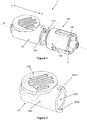
- FIG 1 shows a dosing unit 1 in accordance with the present disclosure in a perspective view.
- the dosing unit 1 includes a valve clutch device 10 in accordance with the present disclosure and a stationary member 20.
- the stationary member is shown in figure 2 in an isolated perspective view.
- proximal and distal are used as follows: A movement of the piston of the dosing unit along the central axis that decreases the liquid filled volume of the dosing unit is a movement from the distal into the proximal direction. Likewise, a movement of the piston that increases the liquid-filled volume is a movement from the proximal into the distal direction. A piston movement into the proximal direction is also referred to as “advancement”, while a piston movement into the distal direction is also referred to as "retraction”. In figure 1 , the proximal and distal direction are indicated by “p” and "d”, respectively. In the further figures that show individual components of the dosing unit 1, the same perspective is used.
- the stationary member 20 has a stationary member body 200 and a stationary member recess 201.
- the stationary member recess 201 has a generally cylindrical inner contour and bears, in an assembled state, a valve member 120 sealing and rotatable around a central axis A.
- the stationary member 200 has two blocking edges 202a, 202b and the valve member 20 has a longitudinal rim 125 that selectively engages the blocking edges 202a, 202b. As will be explained further below, the rim 125 further serves for coupling the valve member 120 with the sleeve member 130.
- the blocking edges 202a, 202b and the rim 125 form a valve member block that limits the rotational movement of the valve member 120 to a range between an inlet valve position and an outlet valve position of exemplarily 180°.
- the valve member 120 At its proximal end, the valve member 120 comprises valve member aperture (not visible).
- the valve member aperture In the inlet valve position, the valve member aperture is aligned and thereby in communication with the inlet aperture (not visible) of the stationary member 200.
- the valve member aperture In the outlet valve position, the valve member aperture is aligned and thereby in communication with the outlet aperture (not visible) of the stationary member 200.
- the valve member aperture In the rotational position between the inlet valve position and the outlet valve position, the valve member aperture is generally fluidic isolated from both the inlet aperture and the outlet aperture.
- the fluidic inlet aperture is fluidic operational coupled with the drug reservoir, such as an insulin reservoir, while the outlet aperture is fluidic operational coupled with an infusion cannula either directly or via an infusion line, such as a tubing.
- the stationary member 20 further includes an optional fluidic platform 202.
- the fluidic platform 202 comprises a fluidic pressure sensor in operated coupling with the outlet aperture and arranged between the outlet aperture and the infusion cannula. Further disclosure regarding this type of pressure sensor can be found in the EP2295096 . This type of pressure sensor, however, is not essential. Other types of pressure sensors as well as further sensors such as flow sensors, may be used additionally, or alternatively. In further embodiments, no sensors are present.
- valve member 120 Inside the valve member 120, an central member 100 (not visible in figure 1 ) is coaxially arranged in screwed engagement as will be explained further below.
- a sleeve member 130 is coaxially arranged around the valve member 120.
- valve member 120 and the central member 100 in an isolated perspective view.
- FIG 3 shows the valve member 120 in an isolated view and figure 4 shows the central member 100 in an isolated view.
- the valve member 120 has a generally elongated shape with a hollow cylindrical valve member body 121 that is sealing and rotational received by the stationary member access 201 as explained before.
- exemplarily three arm members 122 project from the valve member body 121.
- the three arm members 122 have an inner thread 123.
- the inner thread 123 is designed for favourably play-free engagement with a corresponding outer thread 102 of the central member 100. Favourably, the arm members 122 exert some inwards-directed radial force, thus biasing the threaded engagement.
- the arm members 122 At their rear or distal ends, the arm members 122 have radially outwards-directed protrusions 124.
- the function of the protrusions 124 will be discussed further below in the context of the valve operation.
- the circumferential surfaces of the arm members 122 further serve as coupling pin blocks 122a as will also be discussed in the context of valve operation.
- valve member 120 In a front or proximal end section, the valve member 120 has a generally cylindrical valve member head 126, that is designed for engaging the stationary member 200 exemplarily via a biased snap fit (see also figure 1 ).
- the central member 100 has an elongated body (not referenced) that carries, in a rear or distal section, the before-mentioned outer thread 102. Proximal from the outer thread 102, the central member 100 has a protruding circumferential central member seal 103 that is designed to be sealing and sliding received by the hollow cylinder of the valve member 120.
- the central member 100 is movable relative to the valve member 120 along the central axis A in a screw-like way between a most retracted and a most advanced position.
- the length of the outer thread 102 corresponds to or is somewhat larger than the displacement range between the most retracted and the most advanced position.
- valve member body 121 For a given relative position of the central member 100 relative to the valve member 120, a volume exists inside the valve member body 121 that is generally fluidic isolated, but may, via the valve member aperture as explained before, be in fluidic communication with the inlet valve aperture in the inlet valve position or with the outlet valve aperture in the outlet valve position, respectively.
- the valve member 120 accordingly serves as cylinder and the central member 100 serves as piston. Liquid can be drawn into the cylinder by moving central member/piston 100 in the retracted (distal) direction with the valve member aperture being in fluidic communication with the inlet aperture. Similarly, liquid can be expelled out of the cylinder by moving the central member/piston 100 into the advanced (proximal) direction with the valve member aperture being in fluidic communication with the outlet aperture.
- the central member has a generally cylindrical central member head 104 of reduced outer diameter as compared to the central member body.
- the central member head 104 In the most advanced (most proximal) position of the central member 100 relative to the valve member 120, the central member head 104 is received inside the valve member head 126. It is to be noted, however, that the presence of the valve member head 126 and the central member head 104 is not essential.
- the proximal front surface of the central member 100 and the inner front surface of the valve member body 121 may be flat or have another suited shape.
- the central member 100 further has a drive coupler 101.
- the drive coupler 101 is exemplarily realized by a an elongated recesses 101 that extends along the central axis A and has a non-circular (exemplarily cross -shaped) cross section.
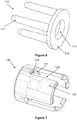
- Figure 5 shows the drive member 3 in an isolated perspective view.
- the drive member 3 is of generally elongated shape and comprises an elongated drive pin 30 of non-circular cross section.
- the drive pin 30 is dimensioned to fit into the recesses 101 with sliding and substantially play free engagement.
- the drive member 3 comprises an motor coupler 32 that is exemplarily realized as non-circular recesses of, for example, star-shaped cross-section. Via the motor coupler 32, the drive member 3 receive, in operation, a drive torque that is transmitted to the central member 100 and/or the valve member 120 as will be explained further below.
- the motor coupler 32 is arranged in a cylindrical distal section 33 of the drive member 3.
- Figure 6 shows the coupling member 110 of the valve clutch device 10 in an isolated perspective view.
- the coupling member 110 comprises a disk -shaped coupling member base 112 with a central bore-like through-opening 113.
- the through-opening 113 is dimensioned to receive the distal section 33 of the drive member 3 in sliding engagement, such that the coupling member base 112 is arranged rotatable around the central member drive member 3.
- the coupling member 110 is arranged proximal of the drive member 3.
- a number of exemplarily three coupling pins 111 project from the coupling member base 112 in proximal direction. In an assembled state, they extend parallel to and around the threaded central member section 102 and contact the threaded central member section 102 in frictional engagement.
- FIG. 7 shows the sleeve member 130 of the of clutch device 10 in an isolated perspective view.
- the sleeve member 130 has a general tubular shape with a sleeve body 133.
- the sleeve member 130 comprises longitudinal sleeve slots 132 that correspond in numbers to the arm members 122 of the valve member 120.
- the sleeve member 130 is arranged around the coupling member 110 and the central member 100. Further in the assembled state, the protrusions 124 radially project into the sleeve slots 132.
- the engagement of the protrusions 124 with the sleeve slots rotationally couple, together with the engagement of the rim 125 with the notch 134, the valve member 120 with the sleeve member 130.
- the sleeve member 130 further comprises a notch 134, the notch 134 extending axially on the inside of the coupling sleeve 130.
- the notch 134 receives and operationally engages the rim 125 of the valve member 120, thus rotatable coupling the valve member 120 and the sleeve member 130.
- the sleeve device 130 further comprises a number of clamping members 131 in form of protrusions that extend radially inward from the body of the sleeve member 130 in a proximal section of the sleeve member 130, as best visible in the following figures.
- the clamping members 131 have a convex cross section and are designed to selectively clamping the coupling pins 111 to the threaded central member section 102.
- valve clutch device 10 In a first configuration providing a drive torque allows the central member 100 to move inside and relative to the valve member 120 in a screw-like manner, with the valve member 120 staying in rest.]
- the corresponding configuration of the valve clutch device 10 is referred to as "unengaged configuration".
- unengaged configuration liquid can be drawn into the dosing unit 1 by moving the central member 100 -which serves as piston - into the distal direction. Similarly, liquid can be expelled out of the dosing unit 1 by moving the central member 100 into the proximal direction.
- the central member 100 and the valve member 120 are rotationally coupled via the coupling member 110 and the sleeve member 130.
- a drive torque that is applied to the central member 100 is transmitted to the valve member 120. Consequently, the central member 100 and the valve member 120 are rotated relative to and inside the stationary member 20 between the inlet valve position and the outlet valve position, respectively. Between the central member 100 and the valve member 120, no relative movement occurs in the engaged configuration.
- Figure 8 shows the central member 100, the sleeve member 130, and the coupling pins 111 of the coupling member 110 in a perspective sectional view and in an assembled state, with the section plane being indicated in figure 1 .
- Figure 8 shows the components in the engaged configuration of the valve clutch device 10.
- the clamping members 131 clamp the coupling pins 111 against the central member 100 (more particularly, against the threaded central member section 102), such that sticking friction is present between the central member 100 and the coupling pins 111, as well as between the coupling pins 111 and the sleeve member 130.
- No relative motion between the central member 100, the coupling member 110, and the sleeve member 130 can accordingly occur in this engaged configuration.
- Exerting a driving torque onto the central member 100 accordingly results in a common rotational movement of the central member 100, the coupling member 110, and the sleeve member 130 in the engaged configuration.
- the valve member 120 is rotationally coupled to the sleeve member 130 via engagement of the rim 125 and the notch 134, also the valve member 120 moves together with the sleeve member 130 in the engaged configuration.
- the central member 100, the coupling pins 111, and the sleeve member 130 are, in contrast, rotatable relative to each other.
- the coupling pins 111 are not clamped by the clamping members 131 and can accordingly not transmit a driving torque from the central member 100 to the sleeve member 130.
- the central member 100 can accordingly rotate independent from the sleeve member 130 and the valve member 120 in the unengaged configuration.
- FIG. 9a to 9e illustrate the operation of the valve clutch device 10 for switching between the inlet valve position and the outlet valve position, respectively.
- Figure 9a shows the situation when the rotational direction of the drive, that is, the direction of the drive torque that is applied to the central member 100, is reversed. It is assumed that, prior to the situation as shown in figure 9a , the central member 100 has been rotated in a counter-clockwise direction (counter to the direction as indicated by arrow R) and now starts rotation in the clockwise direction (into the direction as indicated by arrow R). In the situation as shown in figure 9a , the valve member aperture is in alignment and fluidic coupling with the inlet aperture as explained before.
- the central member 100 has, prior to the situation shown in Figure 9a , accordingly be moved into the distal direction, thus increasing the liquid-filled volume of the dosing unit 1 as explained before. It can further be seen from Fig. 9a that the coupling pins 111 each abut a corresponding coupling pin block 122a. The situation of figure 9a further corresponds to the situation as shown in figure 1 with the rim 125 abutting the upper blocking edge 202a.
- the central member begins a screw-like motion to the proximal direction. Due to the frictional engagement of the coupling pins 11 1 with the central member 100 as explained before, a corresponding movement is carried out by the coupling member 110, with the threaded central member section 102 and the coupling pins 111 being in sticking frictional engagement.
- the sleeve member 130 and the valve member 120 do not move and maintain their position.
- the central member 100, the coupling member 110 and the sleeve member 120 will, due to the before-explained clamping, rotate together into the direction R. Since the valve member 120 is, via the engagement of the rim 125 with the notch 134 and via the engagement of the protrusions 124 with the sleeve slots 132, coupled to the sleeve member 130, the valve member carries out the same rotational movement and accordingly rotates within the stationary member recess 201. The contact between the rim 125 and the blocking edge 202a is cancelled as the valve member 120 starts moving.
- the rim 125 will, after a rotation about 180°, abut the lower blocking edge 202b, thereby preventing further movement of the valve member 120 and the sleeve member 130.
- This situation is shown in figure 9d .
- the valve member aperture is aligned with the outlet aperture.
Description
- The present invention lies in the field of dosing units for liquid drugs as used in the context of drug infusion. The invention further lies in the field of valve clutch devices that form part of some dosing units.
- Ambulatory infusion devices are well known in the art for the administration of liquid drugs, for example in the therapy of Diabetes Mellitus by Continuous Subcutaneous Insulin Infusion (CSII) as well as in pain therapy or cancer therapy. Ambulatory infusion devices are available from a number of supplies, such as Roche Diagnostics GmbH, Germany, or Medtronic MiniMed Inc., CA, USA.
- The
EP1970677A1 discloses a system with a miniaturized metering piston pump with a dosing cylinder that is repeatedly coupled to and filled from a larger reservoir, followed by coupling the dosing cylinder to an infusion site and infusing the liquid drug out of the dosing cylinder in incremental steps and over an extended time period via displacing a piston. For alternatively coupling the dosing cylinder to the reservoir and the infusion site, a valve system is proposed. Reference is made to theEP1970677A1 for the basic operational principle and design of a dosing unit in accordance with the present document. Generally, a miniaturized metering piston pump according to the principle as laid down in theEP1970677A1 is in this document referred to as "dosing unit". More particularly, the dosing unit is a generally disposable fluidic unit that is, for its application, coupled to further infusion pump components or devices, such as a drive unit which may include one or more actuators/motors, an electronic control unit, a liquid drug reservoir, and an infusion cannula, and is discarded after a use period of generally a few days up to two weeks. Particular aspects and embodiments of dosing units and their operation that may be applied, alone or in combination, in the context of the present invention are disclosed in e.g.,EP2510962 ,EP2510960 ,EP2696915 ,EP2457602 ,WO2012/069308 ,WO2013/029999 ,EP2753380 ,EP2163273 ,EP2361646 . - The invention is set out in the appended set of claims.
- Dosing units of the before-mentioned type may, in some embodiments, be realized with a single actuator (typically a motor) that is used for both valve switching and piston displacement. For those embodiments, however, the coupling mechanism for selectively coupling the drive with the valve and/or the piston is a particularly critical aspect. Favourably, valve switching shall be possible at any piston position within the cylinder by simply reversing the driving direction. Furthermore, the process of valve switching shall be associated with no or substantially no piston displacement in order to minimize dosing errors.
- Further requirements that are to be met as far as possible are high reliability over the usage time, small dimensions and cost-efficiency since the coupling mechanism is part of a generally disposable product.
- It is an overall object of the present disclosure to improve the state of the art in the field of liquid drug dosing units. Favourably, some or all of the disadvantages of prior art solutions should be avoided or reduced.
- The overall objective is in a general way met by the subject matter of the independent claim.
- Exemplary and/or particularly favourable embodiments are defined by the subject matter of the dependent claims and the overall disclosure of the present document.
- In an aspect, the overall object is achieved by providing a valve clutch device. The valve clutch device includes a central member. The central member extends along a central axis and includes a drive coupler that is designed to receive a driving torque around the central axis.
- The valve clutch device further includes a coupling member. The coupling member includes at least one coupling pin, the at least one coupling pin extending parallel to the central axis.
- The valve clutch device further includes a valve member. The valve member is beared rotatable around the central axis between an inlet valve position and an outlet valve position.
- The valve clutch device further includes a sleeve member. The sleeve member is designed to rotationally engage the valve member and includes at least one clamping member.
- A valve member block, the valve member block blocking rotational movement of the valve member in the inlet valve position and the outlet valve position, respectively.
- The valve clutch device is reversibly changeable between an unengaged configuration where a driving torque that is received by the central member is not transmitted to the sleeve member and an engaged configuration where the at least one coupling pin is clamped between the elongated central member and the at least one clamping member, thereby transmitting a driving torque that is received by the central member via the sleeve member to the valve member.
- In some embodiments of the valve clutch device, the at least one coupling pin is in frictional engagement with the central member.
- In some embodiments of the valve clutch device, the frictional engagement of the at least one coupling pin and the central member is changeable between a sliding frictional engagement and sticking frictional engagement in dependence of an angular position of the at least one coupling pin relative to the central member and/or in dependence of a direction of rotation of the central member around the central axis. The sticking frictional engagement may also be a clamping engagement where the at least one coupling pin is clamped between the central member and the clamping member and is accordingly in sticking frictional engagement with the central member as well as with the clamping member.
- In some embodiments of the valve clutch device, the valve clutch device includes angularly spaced coupling pin blocks and a clamping member is arranged angularly symmetrical between two adjacent coupling pin blocks.
- In some embodiments of the valve clutch device, the coupling pin blocks are formed by arm members of the valve member, the arm members extending generally parallel to the central axis.
- The arm members of such embodiments project, in an assembled state, in distal direction from a valve member body, with gaps being present between the arm members.
- In some embodiments of the valve clutch device, the coupling member includes a plurality of coupling pins and the sleeve member includes a corresponding plurality of associated clamping members. In an exemplary embodiment, three coupling pins and three associated clamping members are present, but another number of clamping members and coupling pins may be used as well. Generally, the coupling pins and clamping members are angularly symmetrically distributed.
- In some embodiments of the valve clutch device, the central member includes a threaded central member section with an outer thread and the valve member includes a corresponding inner thread. By applying a drive torque to the central member, the central member can move in a screw-like way relative to the valve member.
- The valve clutch device includes a valve member block, the valve member block blocking rotational movement of the valve member in the inlet valve position and the outlet valve position, respectively. In an embodiment, the valve member block is realized by a rim that extends along the valve member parallel to the central axis and is arranged to selectively abut and thereby engage blocking edges of a stationary member of a dosing unit or other blocking elements as generally known in the art, such as blocking pins, blocking protrusions or the like.
- In some embodiments of the valve clutch device, the coupling member includes a coupling member base, the coupling member base being rotatable arranged around the central member with the at least one coupling pin projecting from the coupling member base. The coupling member base may especially be disc shape and have an e.g. circular aperture in which, in an assembled state, the central member is received.
- In some embodiments of the valve clutch device, the central member, the coupling member, the sleeve member and the valve member are arranged coaxially with the central axis. In some embodiments of the valve clutch device, the central member is arranged in sealing and sliding engagement inside the valve member, the central member thereby serving as piston member.
- In some embodiments of the valve clutch device, the drive coupler is designed for receiving a drive pin in sliding engagement along the central axis and in substantially rigid rotational engagement with respect to the central axis. Other types of drive engagement, such as a toothed engagements, may be used as well.
- In the valve clutch device, the valve member includes a cylinder and a valve member aperture in fluidic communication with an inner volume of the cylinder.
- In a further aspect, the overall object is achieved by providing a liquid drug dosing unit. The liquid drug dosing unit includes a valve clutch device as discussed before. The liquid drug dosing unit further includes a stationary member. The stationary member bears the valve member sealing and rotatable around the central axis. The stationary member further includes an inlet aperture and an outlet aperture, wherein the valve member aperture is in fluidic communication with the inlet aperture in the inlet valve position and alternatively in fluidic communication with the outlet aperture in the outlet vale position.
-
- Figure 1
- shows a dosing unit in accordance with the present disclosure in a perspective view;
- Figure 2
- shows a stationary member in an isolated perspective view;
- Figure 3
- shows a valve member in an isolated perspective view;
- Figure 4
- shows a central member in an isolated perspective view;
- Figure 5
- shows a drive member in an isolated perspective view;
- Figure 6
- shows a coupling member in an isolated schematic view;
- Figure 7
- shows a sleeve member in an isolated schematic view;
- Figure 8
- shows some components of a valve clutch device in an assembled cross-sectional view;
- Figure 9a - 9e
- illustrate a valve switching sequence.
- In the following, reference is first made to
figure 1 and figure 2. Figure 1 shows adosing unit 1 in accordance with the present disclosure in a perspective view. Thedosing unit 1 includes a valveclutch device 10 in accordance with the present disclosure and astationary member 20. The stationary member is shown infigure 2 in an isolated perspective view. - In this document, the directional terms "proximal" and "distal" are used as follows: A movement of the piston of the dosing unit along the central axis that decreases the liquid filled volume of the dosing unit is a movement from the distal into the proximal direction. Likewise, a movement of the piston that increases the liquid-filled volume is a movement from the proximal into the distal direction. A piston movement into the proximal direction is also referred to as "advancement", while a piston movement into the distal direction is also referred to as "retraction". In
figure 1 , the proximal and distal direction are indicated by "p" and "d", respectively. In the further figures that show individual components of thedosing unit 1, the same perspective is used. - With respect to the figures, it is further noted that features that are present more than once in the same or substantially the same way are generally only referenced once. Furthermore, features that are visible in more than one figure may not be referenced in all of them.
- The
stationary member 20 has astationary member body 200 and astationary member recess 201. Thestationary member recess 201 has a generally cylindrical inner contour and bears, in an assembled state, avalve member 120 sealing and rotatable around a central axis A. Thestationary member 200 has two blockingedges valve member 20 has alongitudinal rim 125 that selectively engages the blockingedges rim 125 further serves for coupling thevalve member 120 with thesleeve member 130. - In combination, the blocking
edges rim 125 form a valve member block that limits the rotational movement of thevalve member 120 to a range between an inlet valve position and an outlet valve position of exemplarily 180°. - At its proximal end, the
valve member 120 comprises valve member aperture (not visible). In the inlet valve position, the valve member aperture is aligned and thereby in communication with the inlet aperture (not visible) of thestationary member 200. In the outlet valve position, the valve member aperture is aligned and thereby in communication with the outlet aperture (not visible) of thestationary member 200. In the rotational position between the inlet valve position and the outlet valve position, the valve member aperture is generally fluidic isolated from both the inlet aperture and the outlet aperture. - In an operational state, the fluidic inlet aperture is fluidic operational coupled with the drug reservoir, such as an insulin reservoir, while the outlet aperture is fluidic operational coupled with an infusion cannula either directly or via an infusion line, such as a tubing.
- The
stationary member 20 further includes an optional fluidic platform 202. The fluidic platform 202 comprises a fluidic pressure sensor in operated coupling with the outlet aperture and arranged between the outlet aperture and the infusion cannula. Further disclosure regarding this type of pressure sensor can be found in theEP2295096 . This type of pressure sensor, however, is not essential. Other types of pressure sensors as well as further sensors such as flow sensors, may be used additionally, or alternatively. In further embodiments, no sensors are present. - Inside the
valve member 120, an central member 100 (not visible infigure 1 ) is coaxially arranged in screwed engagement as will be explained further below. Asleeve member 130 is coaxially arranged around thevalve member 120. - In the following, reference is additionally made to
figure 3, and figure 4 . showing thevalve member 120 and thecentral member 100 in an isolated perspective view. -
Figure 3 shows thevalve member 120 in an isolated view andfigure 4 shows thecentral member 100 in an isolated view. Thevalve member 120 has a generally elongated shape with a hollow cylindricalvalve member body 121 that is sealing and rotational received by thestationary member access 201 as explained before. In distal direction, exemplarily threearm members 122 project from thevalve member body 121. - In a rear or distal end section, the three
arm members 122 have aninner thread 123. Theinner thread 123 is designed for favourably play-free engagement with a correspondingouter thread 102 of thecentral member 100. Favourably, thearm members 122 exert some inwards-directed radial force, thus biasing the threaded engagement. - At their rear or distal ends, the
arm members 122 have radially outwards-directedprotrusions 124. The function of theprotrusions 124 will be discussed further below in the context of the valve operation. The circumferential surfaces of thearm members 122 further serve ascoupling pin blocks 122a as will also be discussed in the context of valve operation. - In a front or proximal end section, the
valve member 120 has a generally cylindricalvalve member head 126, that is designed for engaging thestationary member 200 exemplarily via a biased snap fit (see alsofigure 1 ). - The
central member 100 has an elongated body (not referenced) that carries, in a rear or distal section, the before-mentionedouter thread 102. Proximal from theouter thread 102, thecentral member 100 has a protruding circumferentialcentral member seal 103 that is designed to be sealing and sliding received by the hollow cylinder of thevalve member 120. - Via the engagement of the
outer thread 102 with the inner threadedsegments 123, thecentral member 100 is movable relative to thevalve member 120 along the central axis A in a screw-like way between a most retracted and a most advanced position. The length of theouter thread 102 corresponds to or is somewhat larger than the displacement range between the most retracted and the most advanced position. - For a given relative position of the
central member 100 relative to thevalve member 120, a volume exists inside thevalve member body 121 that is generally fluidic isolated, but may, via the valve member aperture as explained before, be in fluidic communication with the inlet valve aperture in the inlet valve position or with the outlet valve aperture in the outlet valve position, respectively. Thevalve member 120 accordingly serves as cylinder and thecentral member 100 serves as piston. Liquid can be drawn into the cylinder by moving central member/piston 100 in the retracted (distal) direction with the valve member aperture being in fluidic communication with the inlet aperture. Similarly, liquid can be expelled out of the cylinder by moving the central member/piston 100 into the advanced (proximal) direction with the valve member aperture being in fluidic communication with the outlet aperture. - At its proximal end, the central member has a generally cylindrical
central member head 104 of reduced outer diameter as compared to the central member body. In the most advanced (most proximal) position of thecentral member 100 relative to thevalve member 120, thecentral member head 104 is received inside thevalve member head 126. It is to be noted, however, that the presence of thevalve member head 126 and thecentral member head 104 is not essential. Alternatively, the proximal front surface of thecentral member 100 and the inner front surface of thevalve member body 121 may be flat or have another suited shape. - In a rear or distal section, generally overlapping with the
outer thread 102, thecentral member 100 further has adrive coupler 101. Thedrive coupler 101 is exemplarily realized by a anelongated recesses 101 that extends along the central axis A and has a non-circular (exemplarily cross -shaped) cross section. - In the following, reference is additionally made to
figure 5. Figure 5 shows thedrive member 3 in an isolated perspective view. Thedrive member 3 is of generally elongated shape and comprises anelongated drive pin 30 of non-circular cross section. Thedrive pin 30 is dimensioned to fit into therecesses 101 with sliding and substantially play free engagement. At its distal end, thedrive member 3 comprises anmotor coupler 32 that is exemplarily realized as non-circular recesses of, for example, star-shaped cross-section. Via themotor coupler 32, thedrive member 3 receive, in operation, a drive torque that is transmitted to thecentral member 100 and/or thevalve member 120 as will be explained further below. Themotor coupler 32 is arranged in a cylindricaldistal section 33 of thedrive member 3. - In the following, reference is additionally made to
figure 6. Figure 6 shows thecoupling member 110 of the valveclutch device 10 in an isolated perspective view. Thecoupling member 110 comprises a disk -shapedcoupling member base 112 with a central bore-like through-opening 113. The through-opening 113 is dimensioned to receive thedistal section 33 of thedrive member 3 in sliding engagement, such that thecoupling member base 112 is arranged rotatable around the centralmember drive member 3. In an assembled state, thecoupling member 110 is arranged proximal of thedrive member 3. - A number of exemplarily three
coupling pins 111 project from thecoupling member base 112 in proximal direction. In an assembled state, they extend parallel to and around the threadedcentral member section 102 and contact the threadedcentral member section 102 in frictional engagement. - In the following, reference is additionally made to
figure 7. Figure 7 shows thesleeve member 130 of the ofclutch device 10 in an isolated perspective view. Thesleeve member 130 has a general tubular shape with asleeve body 133. Thesleeve member 130 compriseslongitudinal sleeve slots 132 that correspond in numbers to thearm members 122 of thevalve member 120. In an assembled state, thesleeve member 130 is arranged around thecoupling member 110 and thecentral member 100. Further in the assembled state, theprotrusions 124 radially project into thesleeve slots 132. The engagement of theprotrusions 124 with the sleeve slots rotationally couple, together with the engagement of therim 125 with thenotch 134, thevalve member 120 with thesleeve member 130. - In a proximal section, proximal to the
sleeve slots 132, thesleeve member 130 further comprises anotch 134, thenotch 134 extending axially on the inside of thecoupling sleeve 130. In an assembled state, thenotch 134 receives and operationally engages therim 125 of thevalve member 120, thus rotatable coupling thevalve member 120 and thesleeve member 130. - The
sleeve device 130 further comprises a number of clampingmembers 131 in form of protrusions that extend radially inward from the body of thesleeve member 130 in a proximal section of thesleeve member 130, as best visible in the following figures. The clampingmembers 131 have a convex cross section and are designed to selectively clamping the coupling pins 111 to the threadedcentral member section 102. - In the following, operation of the
dosing unit 1 and in particular of the valveclutch device 10 will be described with additional reference tofigure 8 andfigures 9a - 9e . As will become more readily apparent in the following, the valveclutch device 10, and in particular thecoupling member 110 and thesleeve member 130 are core elements this embodiment of a valveclutch device 10. In a first configuration providing a drive torque allows thecentral member 100 to move inside and relative to thevalve member 120 in a screw-like manner, with thevalve member 120 staying in rest.] The corresponding configuration of the valveclutch device 10 is referred to as "unengaged configuration". In the unengaged configuration, liquid can be drawn into thedosing unit 1 by moving the central member 100 -which serves as piston - into the distal direction. Similarly, liquid can be expelled out of thedosing unit 1 by moving thecentral member 100 into the proximal direction. - In the alternative engaged configuration, the
central member 100 and thevalve member 120 are rotationally coupled via thecoupling member 110 and thesleeve member 130. In the engaged configuration, a drive torque that is applied to thecentral member 100 is transmitted to thevalve member 120. Consequently, thecentral member 100 and thevalve member 120 are rotated relative to and inside thestationary member 20 between the inlet valve position and the outlet valve position, respectively. Between thecentral member 100 and thevalve member 120, no relative movement occurs in the engaged configuration. -
Figure 8 shows thecentral member 100, thesleeve member 130, and the coupling pins 111 of thecoupling member 110 in a perspective sectional view and in an assembled state, with the section plane being indicated infigure 1 .Figure 8 shows the components in the engaged configuration of the valveclutch device 10. - In the engaged state, the clamping
members 131 clamp the coupling pins 111 against the central member 100 (more particularly, against the threaded central member section 102), such that sticking friction is present between thecentral member 100 and the coupling pins 111, as well as between the coupling pins 111 and thesleeve member 130. No relative motion between thecentral member 100, thecoupling member 110, and thesleeve member 130 can accordingly occur in this engaged configuration. Exerting a driving torque onto thecentral member 100 accordingly results in a common rotational movement of thecentral member 100, thecoupling member 110, and thesleeve member 130 in the engaged configuration. Furthermore, since thevalve member 120 is rotationally coupled to thesleeve member 130 via engagement of therim 125 and thenotch 134, also thevalve member 120 moves together with thesleeve member 130 in the engaged configuration. - In the unengaged configuration, the
central member 100, the coupling pins 111, and thesleeve member 130 are, in contrast, rotatable relative to each other. In particular, the coupling pins 111 are not clamped by the clampingmembers 131 and can accordingly not transmit a driving torque from thecentral member 100 to thesleeve member 130. Thecentral member 100 can accordingly rotate independent from thesleeve member 130 and thevalve member 120 in the unengaged configuration. - The sectional drawings of
figure 9a to 9e illustrate the operation of the valveclutch device 10 for switching between the inlet valve position and the outlet valve position, respectively. -
Figure 9a shows the situation when the rotational direction of the drive, that is, the direction of the drive torque that is applied to thecentral member 100, is reversed. It is assumed that, prior to the situation as shown infigure 9a , thecentral member 100 has been rotated in a counter-clockwise direction (counter to the direction as indicated by arrow R) and now starts rotation in the clockwise direction (into the direction as indicated by arrow R). In the situation as shown infigure 9a , the valve member aperture is in alignment and fluidic coupling with the inlet aperture as explained before. - Assuming the
outer thread 102 and theinner thread 123 to be right-hand threads, thecentral member 100 has, prior to the situation shown inFigure 9a , accordingly be moved into the distal direction, thus increasing the liquid-filled volume of thedosing unit 1 as explained before. It can further be seen fromFig. 9a that the coupling pins 111 each abut a correspondingcoupling pin block 122a. The situation offigure 9a further corresponds to the situation as shown infigure 1 with therim 125 abutting theupper blocking edge 202a. - As a driving torque is applied in the direction R as shown in
Figure 9a , the central member begins a screw-like motion to the proximal direction. Due to the frictional engagement of the coupling pins 11 1 with thecentral member 100 as explained before, a corresponding movement is carried out by thecoupling member 110, with the threadedcentral member section 102 and the coupling pins 111 being in sticking frictional engagement. Thesleeve member 130 and thevalve member 120, in contrast, do not move and maintain their position. - As the driving torque is further applied into the direction R, the coupling pins 111 will come in contact with the clamping
members 131. This situation is shown inFig. 9b . - As the driving torque is still further applied into the direction R, the driving pins 11 1 are being aligned with clamping
members 131 and are accordingly clamped between the clampingmembers 131 and thecentral member 100, resulting in the coupling pins 111 being in sticking frictional engagement with both the clamping members 131 (and, accordingly, thesleeve member 130 as a whole), and thecentral member 100. This situation is shown inFigure 9c . The change from the situation offigure 9b to the situation offigure 9c corresponds to a change of the valve clutch device from the unengaged to the engaged configuration. - As the driving torque is still further applied into the direction R, the
central member 100, thecoupling member 110 and thesleeve member 120 will, due to the before-explained clamping, rotate together into the direction R. Since thevalve member 120 is, via the engagement of therim 125 with thenotch 134 and via the engagement of theprotrusions 124 with thesleeve slots 132, coupled to thesleeve member 130, the valve member carries out the same rotational movement and accordingly rotates within thestationary member recess 201. The contact between therim 125 and the blockingedge 202a is cancelled as thevalve member 120 starts moving. - As the driving torque is still further applied into the direction R, the
rim 125 will, after a rotation about 180°, abut thelower blocking edge 202b, thereby preventing further movement of thevalve member 120 and thesleeve member 130. This situation is shown infigure 9d . In this situation, the valve member aperture is aligned with the outlet aperture. - As the driving torque is still further applied into the direction R, clamping of the clamping pins 11 1 will be cancelled, and the
central member 100 andcoupling member 110 further rotate in sticking frictional engagement, whilesleeve member 120 and the valve member maintain their position. The cancelling of the clamping corresponds to a change of the valve clutch device from the engaged into the unengaged configuration. - Finally, the coupling pins 111 hit and thereby abut again
coupling pin blocks 122a as shown infigure 9e . With the coupling pins 11 1 abutting thecoupling pin blocks 122a, the valve switching is finished. By comparing the situation as shown infigure 9e with the situation as shown infigure 9a , it can be seen that the configurations are largely identical, except from the sleeve member 130 (and the valve member 120) being rotated by 180° and the coupling pins 11 1 abutting different coupling pin blocks 1 22a. - Subsequently further applying a driving torque into the direction R will result in only the central member carrying out a screw-like movement into the proximal direction, thus reducing the liquid-filled volume of the
dosing unit 1 as explained before. During the further screw-like movement of thecentral member 100, the coupling pins 11 1 are, due to their blocking by thecoupling pin blocks 122a, in sliding frictional engagement with thecentral member 100. - If the direction of the driving torque is reversed, the before-mentioned steps will be run through in the reverse order and the dosing unit will be switched from the outlet valve position into the inlet valve position.
Claims (11)
- Liquid drug dosing unit (1), including a valve clutch device (10) and a stationary member (20), the valve clutch device (10) including:- a central member (100), the central member (100) extending along a central axis (A), the central member (100) including a drive coupler (101), the drive coupler (101) being designed to receive a driving torque around the central axis (A);- a coupling member (110), the coupling member (110) including at least one coupling pin (111), the at least one coupling pin (111) extending parallel to the central axis (A);- a valve member (120) including a cylinder and a valve member aperture in fluidic communication with an inner volume of the cylinder, the valve member (120) being sealingly and rotatably beared by the stationary member (20) around the central axis (A) between an inlet valve position and an outlet valve position;- a sleeve member (130), the sleeve member (130) being designed to rotationally engage the valve member (120), the sleeve member (130) including at least one clamping member (131);- a valve member block (125), the valve member block (125) blocking rotational movement of the valve member (120) in the inlet valve position and the outlet valve position, respectively;the stationary member (20) including an inlet aperture and an outlet aperture, wherein the valve member aperture is in fluidic communication with the inlet aperture in the inlet valve position and aternatively in fluidic communication with the outlet aperture in the outlet vale position;
wherein the valve clutch device (10) is reversibly changeable between an unengaged configuration where a driving torque that is received by the central member (100) is not transmitted to the sleeve member (130) and an engaged configuration where the at least one coupling pin (111) is clamped between the elongated central member (100) and the at least one clamping member (131), thereby transmitting a driving torque that is received by the central member (100) via the sleeve member (130) to the valve member (120). - Liquid drug dosing unit (1) according to claim 1, wherein the at least one coupling pin (111) is in frictional engagement with the central member (100).
- Liquid drug dosing unit (1) according to claim 2, wherein the frictional engagement of the at least one coupling pin (111) and the central member (100) is changeable between a sliding frictional engagement and sticking frictional engagement in dependence of an angular position of the at least one coupling pin (111) relative to the central member (100) and/or in dependence of a direction of rotation of the central member (100) around the central axis (A).
- Liquid drug dosing unit (1) according to either of the preceding claims, wherein the valve clutch device (10) includes angularly spaced coupling pin blocks (122a) and a clamping member (131) is arranged angularly symmetrical between two adjacent coupling pin blocks (122a).
- Liquid drug dosing unit (1) according to claim 4, wherein the coupling pin blocks (122a) are formed by arm members (122) of the valve member (120), the arm members (122) extending generally parallel to the central axis (A).
- Liquid drug dosing unit (1) according to either of the preceding claims, wherein the coupling member (110) includes a plurality of coupling pins (111) and the clamping member (130) includes a corresponding plurality of associated clamping members (131).
- Liquid drug dosing unit (1) according to either of the preceding claims, wherein the central member (100) includes a threaded central member section (102) with an outer thread and the valve member (120) includes a corresponding inner thread (123).
- Liquid drug dosing unit (1) according to either of the preceding claims, wherein the coupling member (110) includes a coupling member base (112), the coupling member base (112) being rotatable arranged around the central member (100) with the at least one coupling pin (111) projecting from the coupling member base (112).
- Liquid drug dosing unit (1) according to either of the preceding claims, wherein the central member (100), the coupling member (110), the clamping member (130) and the valve member are arranged coaxially with the central axis (A).
- Liquid drug dosing unit (1) according to either of the preceding claims, wherein the central member (100) is arranged in sealing and sliding engagement inside the valve member (120), the central member (100) thereby serving as piston member.
- Liquid drug dosing unit (1) according to either of the preceding claims, wherein the drive coupler (101) is designed for receiving a drive pin (30) in sliding engagement along the central axis (A) and in substantially rigid rotational engagement with respect to the central axis (A).
Priority Applications (8)
| Application Number | Priority Date | Filing Date | Title |
|---|---|---|---|
| EP15183669.9A EP3138593B1 (en) | 2015-09-03 | 2015-09-03 | Valve clutch device and dosing unit with a valve clutch device |
| DK15183669.9T DK3138593T3 (en) | 2015-09-03 | 2015-09-03 | Valve coupling device and metering unit with a valve coupling device |
| ES15183669T ES2772026T3 (en) | 2015-09-03 | 2015-09-03 | Valve coupling device and dosing unit with valve coupling device |
| JP2018511727A JP6855456B2 (en) | 2015-09-03 | 2016-08-26 | Administration unit with valve clutch device and valve clutch device |
| PCT/EP2016/070202 WO2017036967A1 (en) | 2015-09-03 | 2016-08-26 | Valve clutch device and dosing unit with a value clutch device |
| KR1020187009213A KR20180048951A (en) | 2015-09-03 | 2016-08-26 | A dosing unit comprising a valve clutch device and a valve clutch device |
| RU2018111525A RU2707169C2 (en) | 2015-09-03 | 2016-08-26 | Coupling joint of hydraulic distributor and dispensing device containing thereof |
| US15/908,411 US10912886B2 (en) | 2015-09-03 | 2018-02-28 | Valve clutch device and dosing unit with a valve clutch device |
Applications Claiming Priority (1)
| Application Number | Priority Date | Filing Date | Title |
|---|---|---|---|
| EP15183669.9A EP3138593B1 (en) | 2015-09-03 | 2015-09-03 | Valve clutch device and dosing unit with a valve clutch device |
Publications (2)
| Publication Number | Publication Date |
|---|---|
| EP3138593A1 EP3138593A1 (en) | 2017-03-08 |
| EP3138593B1 true EP3138593B1 (en) | 2019-12-11 |
Family
ID=54062658
Family Applications (1)
| Application Number | Title | Priority Date | Filing Date |
|---|---|---|---|
| EP15183669.9A Active EP3138593B1 (en) | 2015-09-03 | 2015-09-03 | Valve clutch device and dosing unit with a valve clutch device |
Country Status (8)
| Country | Link |
|---|---|
| US (1) | US10912886B2 (en) |
| EP (1) | EP3138593B1 (en) |
| JP (1) | JP6855456B2 (en) |
| KR (1) | KR20180048951A (en) |
| DK (1) | DK3138593T3 (en) |
| ES (1) | ES2772026T3 (en) |
| RU (1) | RU2707169C2 (en) |
| WO (1) | WO2017036967A1 (en) |
Families Citing this family (6)
| Publication number | Priority date | Publication date | Assignee | Title |
|---|---|---|---|---|
| PT1762259E (en) | 2005-09-12 | 2010-12-10 | Unomedical As | Inserter for an infusion set with a first and second spring units |
| JP2013523233A (en) | 2010-03-30 | 2013-06-17 | ウノメディカル アクティーゼルスカブ | Medical device |
| WO2012123274A1 (en) | 2011-03-14 | 2012-09-20 | Unomedical A/S | Inserter system with transport protection |
| EP2583715A1 (en) | 2011-10-19 | 2013-04-24 | Unomedical A/S | Infusion tube system and method for manufacture |
| EP3405230A1 (en) | 2016-01-19 | 2018-11-28 | Unomedical A/S | Cannula and infusion devices |
| WO2020236796A1 (en) | 2019-05-20 | 2020-11-26 | Unomedical A/S | Rotatable infusion device and methods thereof |
Family Cites Families (9)
| Publication number | Priority date | Publication date | Assignee | Title |
|---|---|---|---|---|
| DK1970677T3 (en) | 2007-03-15 | 2010-02-15 | Hoffann La Roche Ag F | Infusion system with a dosing device |
| DK2163273T3 (en) | 2008-09-12 | 2013-07-29 | Hoffmann La Roche | Dosage unit and outpatient infusion unit with dosage unit |
| DK2295096T3 (en) | 2009-09-11 | 2016-05-23 | Hoffmann La Roche | Micro-fluid chambers for use in liquid drug delivery systems |
| EP2457602A1 (en) | 2010-11-25 | 2012-05-30 | F. Hoffmann-La Roche AG | Infusion pump having dosing unit with safety valve |
| EP2510960B1 (en) | 2011-04-12 | 2017-06-28 | F. Hoffmann-La Roche AG | Infusion pump device with cylinder-piston dosing unit and optical piston position detection |
| EP2510961A1 (en) * | 2011-04-12 | 2012-10-17 | F. Hoffmann-La Roche AG | Infusion pump device with improved priming of the fluidic system and method for priming such an infusion pump device |
| EP2510962A1 (en) | 2011-04-12 | 2012-10-17 | F. Hoffmann-La Roche AG | Infusion pump device with re-filling scheme for cylinder-piston dosing unit |
| WO2013029999A1 (en) | 2011-09-02 | 2013-03-07 | F. Hoffmann-La Roche Ag | Dosing unit for an ambulatory infusion device |
| EP2753380B1 (en) | 2011-09-05 | 2020-05-06 | Roche Diabetes Care GmbH | Hand-held injection device and disposable module |
-
2015
- 2015-09-03 DK DK15183669.9T patent/DK3138593T3/en active
- 2015-09-03 EP EP15183669.9A patent/EP3138593B1/en active Active
- 2015-09-03 ES ES15183669T patent/ES2772026T3/en active Active
-
2016
- 2016-08-26 RU RU2018111525A patent/RU2707169C2/en active
- 2016-08-26 WO PCT/EP2016/070202 patent/WO2017036967A1/en active Application Filing
- 2016-08-26 KR KR1020187009213A patent/KR20180048951A/en not_active Application Discontinuation
- 2016-08-26 JP JP2018511727A patent/JP6855456B2/en active Active
-
2018
- 2018-02-28 US US15/908,411 patent/US10912886B2/en active Active
Non-Patent Citations (1)
| Title |
|---|
| None * |
Also Published As
| Publication number | Publication date |
|---|---|
| JP2018526132A (en) | 2018-09-13 |
| WO2017036967A1 (en) | 2017-03-09 |
| DK3138593T3 (en) | 2020-02-17 |
| KR20180048951A (en) | 2018-05-10 |
| RU2018111525A (en) | 2019-10-04 |
| US20180185573A1 (en) | 2018-07-05 |
| RU2707169C2 (en) | 2019-11-22 |
| JP6855456B2 (en) | 2021-04-07 |
| EP3138593A1 (en) | 2017-03-08 |
| ES2772026T3 (en) | 2020-07-07 |
| RU2018111525A3 (en) | 2019-10-04 |
| US10912886B2 (en) | 2021-02-09 |
Similar Documents
| Publication | Publication Date | Title |
|---|---|---|
| EP3138593B1 (en) | Valve clutch device and dosing unit with a valve clutch device | |
| AU2021200517B2 (en) | Drive mechanisms for drug delivery pumps | |
| US10183113B2 (en) | Ambulatory infusion system including a step switching mechanism for valve control | |
| US10632249B2 (en) | Drug delivery device with needle actuation mechanism | |
| EP2163273B1 (en) | Dosing unit and ambulatory infusion device comprising dosing unit | |
| AU2017294448B2 (en) | Infusion device drive unit with blocking device | |
| US10980937B2 (en) | Dosing unit for use in ambulatory infusion systems |
Legal Events
| Date | Code | Title | Description |
|---|---|---|---|
| PUAI | Public reference made under article 153(3) epc to a published international application that has entered the european phase |
Free format text: ORIGINAL CODE: 0009012 |
|
| STAA | Information on the status of an ep patent application or granted ep patent |
Free format text: STATUS: THE APPLICATION HAS BEEN PUBLISHED |
|
| AK | Designated contracting states |
Kind code of ref document: A1 Designated state(s): AL AT BE BG CH CY CZ DE DK EE ES FI FR GB GR HR HU IE IS IT LI LT LU LV MC MK MT NL NO PL PT RO RS SE SI SK SM TR |
|
| AX | Request for extension of the european patent |
Extension state: BA ME |
|
| STAA | Information on the status of an ep patent application or granted ep patent |
Free format text: STATUS: REQUEST FOR EXAMINATION WAS MADE |
|
| 17P | Request for examination filed |
Effective date: 20170830 |
|
| RBV | Designated contracting states (corrected) |
Designated state(s): AL AT BE BG CH CY CZ DE DK EE ES FI FR GB GR HR HU IE IS IT LI LT LU LV MC MK MT NL NO PL PT RO RS SE SI SK SM TR |
|
| GRAP | Despatch of communication of intention to grant a patent |
Free format text: ORIGINAL CODE: EPIDOSNIGR1 |
|
| STAA | Information on the status of an ep patent application or granted ep patent |
Free format text: STATUS: GRANT OF PATENT IS INTENDED |
|
| INTG | Intention to grant announced |
Effective date: 20190703 |
|
| GRAS | Grant fee paid |
Free format text: ORIGINAL CODE: EPIDOSNIGR3 |
|
| GRAA | (expected) grant |
Free format text: ORIGINAL CODE: 0009210 |
|
| STAA | Information on the status of an ep patent application or granted ep patent |
Free format text: STATUS: THE PATENT HAS BEEN GRANTED |
|
| AK | Designated contracting states |
Kind code of ref document: B1 Designated state(s): AL AT BE BG CH CY CZ DE DK EE ES FI FR GB GR HR HU IE IS IT LI LT LU LV MC MK MT NL NO PL PT RO RS SE SI SK SM TR |
|
| REG | Reference to a national code |
Ref country code: GB Ref legal event code: FG4D |
|
| REG | Reference to a national code |
Ref country code: CH Ref legal event code: EP |
|
| REG | Reference to a national code |
Ref country code: AT Ref legal event code: REF Ref document number: 1211541 Country of ref document: AT Kind code of ref document: T Effective date: 20191215 |
|
| REG | Reference to a national code |
Ref country code: DE Ref legal event code: R096 Ref document number: 602015043348 Country of ref document: DE |
|
| REG | Reference to a national code |
Ref country code: IE Ref legal event code: FG4D |
|
| REG | Reference to a national code |
Ref country code: DK Ref legal event code: T3 Effective date: 20200212 |
|
| REG | Reference to a national code |
Ref country code: SE Ref legal event code: TRGR |
|
| REG | Reference to a national code |
Ref country code: NL Ref legal event code: FP |
|
| REG | Reference to a national code |
Ref country code: LT Ref legal event code: MG4D |
|
| PG25 | Lapsed in a contracting state [announced via postgrant information from national office to epo] |
Ref country code: NO Free format text: LAPSE BECAUSE OF FAILURE TO SUBMIT A TRANSLATION OF THE DESCRIPTION OR TO PAY THE FEE WITHIN THE PRESCRIBED TIME-LIMIT Effective date: 20200311 Ref country code: LV Free format text: LAPSE BECAUSE OF FAILURE TO SUBMIT A TRANSLATION OF THE DESCRIPTION OR TO PAY THE FEE WITHIN THE PRESCRIBED TIME-LIMIT Effective date: 20191211 Ref country code: LT Free format text: LAPSE BECAUSE OF FAILURE TO SUBMIT A TRANSLATION OF THE DESCRIPTION OR TO PAY THE FEE WITHIN THE PRESCRIBED TIME-LIMIT Effective date: 20191211 Ref country code: FI Free format text: LAPSE BECAUSE OF FAILURE TO SUBMIT A TRANSLATION OF THE DESCRIPTION OR TO PAY THE FEE WITHIN THE PRESCRIBED TIME-LIMIT Effective date: 20191211 Ref country code: BG Free format text: LAPSE BECAUSE OF FAILURE TO SUBMIT A TRANSLATION OF THE DESCRIPTION OR TO PAY THE FEE WITHIN THE PRESCRIBED TIME-LIMIT Effective date: 20200311 Ref country code: GR Free format text: LAPSE BECAUSE OF FAILURE TO SUBMIT A TRANSLATION OF THE DESCRIPTION OR TO PAY THE FEE WITHIN THE PRESCRIBED TIME-LIMIT Effective date: 20200312 |
|
| PG25 | Lapsed in a contracting state [announced via postgrant information from national office to epo] |
Ref country code: HR Free format text: LAPSE BECAUSE OF FAILURE TO SUBMIT A TRANSLATION OF THE DESCRIPTION OR TO PAY THE FEE WITHIN THE PRESCRIBED TIME-LIMIT Effective date: 20191211 Ref country code: RS Free format text: LAPSE BECAUSE OF FAILURE TO SUBMIT A TRANSLATION OF THE DESCRIPTION OR TO PAY THE FEE WITHIN THE PRESCRIBED TIME-LIMIT Effective date: 20191211 |
|
| PG25 | Lapsed in a contracting state [announced via postgrant information from national office to epo] |
Ref country code: AL Free format text: LAPSE BECAUSE OF FAILURE TO SUBMIT A TRANSLATION OF THE DESCRIPTION OR TO PAY THE FEE WITHIN THE PRESCRIBED TIME-LIMIT Effective date: 20191211 |
|
| REG | Reference to a national code |
Ref country code: ES Ref legal event code: FG2A Ref document number: 2772026 Country of ref document: ES Kind code of ref document: T3 Effective date: 20200707 |
|
| PG25 | Lapsed in a contracting state [announced via postgrant information from national office to epo] |
Ref country code: RO Free format text: LAPSE BECAUSE OF FAILURE TO SUBMIT A TRANSLATION OF THE DESCRIPTION OR TO PAY THE FEE WITHIN THE PRESCRIBED TIME-LIMIT Effective date: 20191211 Ref country code: PT Free format text: LAPSE BECAUSE OF FAILURE TO SUBMIT A TRANSLATION OF THE DESCRIPTION OR TO PAY THE FEE WITHIN THE PRESCRIBED TIME-LIMIT Effective date: 20200506 Ref country code: EE Free format text: LAPSE BECAUSE OF FAILURE TO SUBMIT A TRANSLATION OF THE DESCRIPTION OR TO PAY THE FEE WITHIN THE PRESCRIBED TIME-LIMIT Effective date: 20191211 Ref country code: CZ Free format text: LAPSE BECAUSE OF FAILURE TO SUBMIT A TRANSLATION OF THE DESCRIPTION OR TO PAY THE FEE WITHIN THE PRESCRIBED TIME-LIMIT Effective date: 20191211 |
|
| PG25 | Lapsed in a contracting state [announced via postgrant information from national office to epo] |
Ref country code: IS Free format text: LAPSE BECAUSE OF FAILURE TO SUBMIT A TRANSLATION OF THE DESCRIPTION OR TO PAY THE FEE WITHIN THE PRESCRIBED TIME-LIMIT Effective date: 20200411 Ref country code: SK Free format text: LAPSE BECAUSE OF FAILURE TO SUBMIT A TRANSLATION OF THE DESCRIPTION OR TO PAY THE FEE WITHIN THE PRESCRIBED TIME-LIMIT Effective date: 20191211 Ref country code: SM Free format text: LAPSE BECAUSE OF FAILURE TO SUBMIT A TRANSLATION OF THE DESCRIPTION OR TO PAY THE FEE WITHIN THE PRESCRIBED TIME-LIMIT Effective date: 20191211 |
|
| REG | Reference to a national code |
Ref country code: DE Ref legal event code: R097 Ref document number: 602015043348 Country of ref document: DE |
|
| REG | Reference to a national code |
Ref country code: AT Ref legal event code: MK05 Ref document number: 1211541 Country of ref document: AT Kind code of ref document: T Effective date: 20191211 |
|
| PLBE | No opposition filed within time limit |
Free format text: ORIGINAL CODE: 0009261 |
|
| STAA | Information on the status of an ep patent application or granted ep patent |
Free format text: STATUS: NO OPPOSITION FILED WITHIN TIME LIMIT |
|
| 26N | No opposition filed |
Effective date: 20200914 |
|
| PG25 | Lapsed in a contracting state [announced via postgrant information from national office to epo] |
Ref country code: SI Free format text: LAPSE BECAUSE OF FAILURE TO SUBMIT A TRANSLATION OF THE DESCRIPTION OR TO PAY THE FEE WITHIN THE PRESCRIBED TIME-LIMIT Effective date: 20191211 Ref country code: AT Free format text: LAPSE BECAUSE OF FAILURE TO SUBMIT A TRANSLATION OF THE DESCRIPTION OR TO PAY THE FEE WITHIN THE PRESCRIBED TIME-LIMIT Effective date: 20191211 |
|
| PG25 | Lapsed in a contracting state [announced via postgrant information from national office to epo] |
Ref country code: PL Free format text: LAPSE BECAUSE OF FAILURE TO SUBMIT A TRANSLATION OF THE DESCRIPTION OR TO PAY THE FEE WITHIN THE PRESCRIBED TIME-LIMIT Effective date: 20191211 |
|
| PG25 | Lapsed in a contracting state [announced via postgrant information from national office to epo] |
Ref country code: MC Free format text: LAPSE BECAUSE OF FAILURE TO SUBMIT A TRANSLATION OF THE DESCRIPTION OR TO PAY THE FEE WITHIN THE PRESCRIBED TIME-LIMIT Effective date: 20191211 |
|
| REG | Reference to a national code |
Ref country code: BE Ref legal event code: MM Effective date: 20200930 |
|
| PG25 | Lapsed in a contracting state [announced via postgrant information from national office to epo] |
Ref country code: LU Free format text: LAPSE BECAUSE OF NON-PAYMENT OF DUE FEES Effective date: 20200903 |
|
| PG25 | Lapsed in a contracting state [announced via postgrant information from national office to epo] |
Ref country code: BE Free format text: LAPSE BECAUSE OF NON-PAYMENT OF DUE FEES Effective date: 20200930 Ref country code: IE Free format text: LAPSE BECAUSE OF NON-PAYMENT OF DUE FEES Effective date: 20200903 |
|
| PG25 | Lapsed in a contracting state [announced via postgrant information from national office to epo] |
Ref country code: TR Free format text: LAPSE BECAUSE OF FAILURE TO SUBMIT A TRANSLATION OF THE DESCRIPTION OR TO PAY THE FEE WITHIN THE PRESCRIBED TIME-LIMIT Effective date: 20191211 Ref country code: MT Free format text: LAPSE BECAUSE OF FAILURE TO SUBMIT A TRANSLATION OF THE DESCRIPTION OR TO PAY THE FEE WITHIN THE PRESCRIBED TIME-LIMIT Effective date: 20191211 Ref country code: CY Free format text: LAPSE BECAUSE OF FAILURE TO SUBMIT A TRANSLATION OF THE DESCRIPTION OR TO PAY THE FEE WITHIN THE PRESCRIBED TIME-LIMIT Effective date: 20191211 |
|
| PG25 | Lapsed in a contracting state [announced via postgrant information from national office to epo] |
Ref country code: MK Free format text: LAPSE BECAUSE OF FAILURE TO SUBMIT A TRANSLATION OF THE DESCRIPTION OR TO PAY THE FEE WITHIN THE PRESCRIBED TIME-LIMIT Effective date: 20191211 |
|
| PGFP | Annual fee paid to national office [announced via postgrant information from national office to epo] |
Ref country code: SE Payment date: 20220908 Year of fee payment: 8 |
|
| PGFP | Annual fee paid to national office [announced via postgrant information from national office to epo] |
Ref country code: NL Payment date: 20230822 Year of fee payment: 9 |
|
| PGFP | Annual fee paid to national office [announced via postgrant information from national office to epo] |
Ref country code: IT Payment date: 20230822 Year of fee payment: 9 Ref country code: GB Payment date: 20230823 Year of fee payment: 9 |
|
| PGFP | Annual fee paid to national office [announced via postgrant information from national office to epo] |
Ref country code: FR Payment date: 20230822 Year of fee payment: 9 Ref country code: DK Payment date: 20230822 Year of fee payment: 9 Ref country code: DE Payment date: 20230822 Year of fee payment: 9 |
|
| PGFP | Annual fee paid to national office [announced via postgrant information from national office to epo] |
Ref country code: ES Payment date: 20231002 Year of fee payment: 9 |
|
| PGFP | Annual fee paid to national office [announced via postgrant information from national office to epo] |
Ref country code: CH Payment date: 20231001 Year of fee payment: 9 |