EP3138427A1 - Liquid supply, atomizer and electronic cigarette having same - Google Patents
Liquid supply, atomizer and electronic cigarette having same Download PDFInfo
- Publication number
- EP3138427A1 EP3138427A1 EP16200372.7A EP16200372A EP3138427A1 EP 3138427 A1 EP3138427 A1 EP 3138427A1 EP 16200372 A EP16200372 A EP 16200372A EP 3138427 A1 EP3138427 A1 EP 3138427A1
- Authority
- EP
- European Patent Office
- Prior art keywords
- liquid
- sliding block
- engaging part
- atomizing device
- atomizer
- Prior art date
- Legal status (The legal status is an assumption and is not a legal conclusion. Google has not performed a legal analysis and makes no representation as to the accuracy of the status listed.)
- Granted
Links
Images


Classifications
-
- A—HUMAN NECESSITIES
- A24—TOBACCO; CIGARS; CIGARETTES; SIMULATED SMOKING DEVICES; SMOKERS' REQUISITES
- A24F—SMOKERS' REQUISITES; MATCH BOXES; SIMULATED SMOKING DEVICES
- A24F40/00—Electrically operated smoking devices; Component parts thereof; Manufacture thereof; Maintenance or testing thereof; Charging means specially adapted therefor
- A24F40/40—Constructional details, e.g. connection of cartridges and battery parts
- A24F40/42—Cartridges or containers for inhalable precursors
-
- A—HUMAN NECESSITIES
- A24—TOBACCO; CIGARS; CIGARETTES; SIMULATED SMOKING DEVICES; SMOKERS' REQUISITES
- A24F—SMOKERS' REQUISITES; MATCH BOXES; SIMULATED SMOKING DEVICES
- A24F40/00—Electrically operated smoking devices; Component parts thereof; Manufacture thereof; Maintenance or testing thereof; Charging means specially adapted therefor
- A24F40/40—Constructional details, e.g. connection of cartridges and battery parts
- A24F40/48—Fluid transfer means, e.g. pumps
- A24F40/485—Valves; Apertures
-
- B—PERFORMING OPERATIONS; TRANSPORTING
- B65—CONVEYING; PACKING; STORING; HANDLING THIN OR FILAMENTARY MATERIAL
- B65D—CONTAINERS FOR STORAGE OR TRANSPORT OF ARTICLES OR MATERIALS, e.g. BAGS, BARRELS, BOTTLES, BOXES, CANS, CARTONS, CRATES, DRUMS, JARS, TANKS, HOPPERS, FORWARDING CONTAINERS; ACCESSORIES, CLOSURES, OR FITTINGS THEREFOR; PACKAGING ELEMENTS; PACKAGES
- B65D43/00—Lids or covers for rigid or semi-rigid containers
- B65D43/14—Non-removable lids or covers
- B65D43/20—Non-removable lids or covers linearly slidable
-
- A—HUMAN NECESSITIES
- A24—TOBACCO; CIGARS; CIGARETTES; SIMULATED SMOKING DEVICES; SMOKERS' REQUISITES
- A24F—SMOKERS' REQUISITES; MATCH BOXES; SIMULATED SMOKING DEVICES
- A24F40/00—Electrically operated smoking devices; Component parts thereof; Manufacture thereof; Maintenance or testing thereof; Charging means specially adapted therefor
- A24F40/10—Devices using liquid inhalable precursors
Definitions
- the present invention relates to electronic cigarettes, and particularly to a liquid supply, an atomizer having same, and an electronic cigarette using same.
- a typical atomizer includes a liquid supply and an atomizing assembly.
- the liquid supply is configured for storing tobacco liquid, and the tobacco liquid is usually sealed by aluminum foil.
- the atomizing assembly includes a pricking component. When the liquid supply is coupled to the atomizing assembly, the pricking component pierces the aluminum foil, so that the tobacco liquid flows into the atomizing assembly. However, when replacing the liquid supply with a new one, the tobacco liquid remained in the liquid supply may flow out and pollute the atomizing assembly. Accordingly, user experience of the atomizer is unsatisfactory.
- the present disclosure relates to an atomizer includes an atomizing device and a liquid supply.
- the atomizing device includes an engaging part.
- the liquid supply includes a liquid chamber.
- the liquid supply includes a connecting end and a liquid outlet defined in the connecting end.
- the engaging part defines a liquid inlet through which tobacco liquid can flow into the atomizing device.
- the liquid supply further includes a sliding block slidable between a first position and a second position. When the sliding block is in the first position, the sliding block seals the liquid outlet; when the sliding block is in the second position, the liquid outlet is opened.
- the engaging part is capable of sliding along a predetermined track to form a snap-fit connection with the connecting end, and simultaneously driving the sliding block to move from the first position to the second position.
- outside refers to a region that is beyond the outermost confines of a physical object.
- inside indicates that at least a portion of a region is partially contained within a boundary formed by the object.
- substantially is defined to be essentially conforming to the particular dimension, shape or other word that substantially modifies, such that the component need not be exact. For example, substantially cylindrical means that the object resembles a cylinder, but can have one or more deviations from a true cylinder.
- comprising when utilized, means “including, but not necessarily limited to”; it specifically indicates open-ended inclusion or membership in the so-described combination, group, series and the like.
- the liquid supply 10 is configured (i.e., structured and arranged) for coupling with an atomizing device 20 to form an atomizer.
- the liquid supply 10 includes a housing 101 and a connecting end 102 at an end of the housing 101.
- the housing 101 defines a liquid chamber 103 for storing tobacco liquid.
- a mouthpiece 113 is provided at the other end of the housing 101.
- An air pipe 112 is further provided in the housing 101.
- the air pipe 112 extends along an axial direction of the housing 101, and communicates with the mouthpiece 112.
- An annular space is formed between the air pipe 112 and the housing 101, and serves as the liquid chamber 103.
- the housing 101, the mouthpiece 113 and the air pipe 112 are integrally formed.
- the connecting end 102 defines a liquid outlet 104.
- a certain mechanism is used to seal or open the liquid outlet 104, thus controlling flow of tobacco liquid in the liquid chamber.
- a sliding block 108 is arranged in the connecting end 102, and slidable between a first position and a second position (the first and second positions will be described in detail later).
- the sliding block 108 When the sliding block 108 is in the first position, the sliding block 108 seals the liquid outlet 104.
- the sliding block 108 When the sliding block 108 is in the second position, the liquid outlet 104 is opened.
- the housing 101 defines an opening at an end, and a sealing element 105 is provided in the end of the housing 101.
- the sealing element 105 is made of silicone or other resilient material.
- a fixing plate 114 is provided on the sealing element 105, and configured for supporting the sealing element 105.
- the sealing element 105 and the fixing plate 114 are both circular in cross-section, and are arranged at an end of the air pipe 112 via central holes, thus sealing the opening of the housing 101.
- the liquid outlet 104 is defined in the sealing element 105. Quite usefully, the liquid outlet 104 deviates from a central hole 115 of the sealing element 105. Air can flow through the central hole 115.
- the sliding block 108 is made of hard material, and abuts tightly against a bottom surface of the sealing element 105.
- the sliding block 108 defines a through hole 109.
- the sliding block 108 seals the liquid outlet 104; when the through hole 109 is aligned or partially aligned with the liquid outlet 104, the sliding block 108 opens the liquid outlet 104.
- a holder 106 and a guiding element 107 are further provided in the connecting end 102.
- the sliding block 108 is assembled in the holder 106.
- the guiding element 107 is configured for guiding an engaging part 202 (as seen in FIG. 3 ) of an atomizing device 20 to move along a predetermined track.
- the holder 106 and the guiding element 107 are sequentially arranged below the sealing element 105, and both are fixed in the housing 101.
- the holder 106 includes a rail, along which the sliding block 108 slides along a straight line.
- the through hole 109 is substantially elliptic in cross-section. A shape of the through hole 109 is identical with that of the liquid outlet 104.
- the guiding element 107 defines a run-through cavity, so that the engaging part 202 can pass through the cavity and drive the sliding block 108 to move.
- the atomizing device 20 includes a main body 201 and the engaging part 202 at an end of the main body 201.
- the engaging part 202 defines a liquid inlet 204.
- the liquid inlet 204 is substantially elliptic.
- a shape of the liquid inlet 204 is identical with that of the liquid outlet 104. Only when the liquid outlet 104 is substantially aligned with the liquid inlet 204, tobacco liquid can flow into the atomizing device 20.
- the engaging part 202 protrudes from an end surface of the main body 201, so that the engaging part 202 can insert into the cavity in the connecting end 102 to form a snap-fit connection.
- two latching parts 206 are formed at two opposite sides of the engaging part 202.
- the guiding element 107 defines an inserting opening 111 and two engaging grooves 110. In the drawings, only one engaging groove 110 is shown (as seen in FIG. 1 ).
- the engaging grooves 110 are configured for coupling with the latching parts 206.
- the engaging part 202 drives the sliding block 108 to move to the first position where the liquid outlet 104 is sealed again.
- the engaging part 202 slides along a track of a straight line.
- a protruding rod 203 is formed on the engaging part 202, and the liquid inlet 204 is defined in the protruding rod 203.
- the engaging part 202 is inserted into the cavity of the guiding element 107, the latching parts 206 are plugged into the inserting opening 111, and the protruding rod 203 is also inserted into the through hole 109 of the sliding block 108.
- the protruding rod 203 drives the sliding block 108 to move together.
- the engaging part 202 defines an air outlet 205. When the sliding block 108 is in the second position, the air outlet 205 aligns with the air pipe 112.
- a height of the protruding rod 203 is equal to or slightly larger than a thickness of the sliding block 108, and a top end of the protruding rod 203 tightly abuts against a bottom surface of the sealing element 105.
- a height of a tubular body, which defines the air outlet 205, is substantially equal to that of the protruding rod 203.
- the protruding rod 203 drives the sliding block 108 to slide to the second position.
- the liquid outlet 104 is aligned with the liquid inlet 204, the air outlet 205 is in communication with the air pipe 112, and the outline of the liquid supply 10 fits well with that of the atomizing device 20.
- the atomizing device 20 further includes a liquid conducting body 207 in the main body 201 and a heating element 208 in the main body 201.
- the liquid conducting body 207 may be made of glass fiber or porous ceramic.
- the heating element 208 is usually a heating wire wound around the liquid conducting body 207.
- an annular fiber cotton layer 210 is further provided below the liquid inlet 204, and two opposite ends of the liquid conducting body contacts with the fiber cotton layer 210.
- the fiber cotton layer 210 can control the tobacco liquid to release slowly to the liquid conducting body 207.
- An electrode assembly 209 is further provided at a bottom of the main body 201, and is connected to the heating element 208.
- the heating element 208 is connected to a power supply via the electrode assembly 209.
- the engaging part 202 drives the sliding block 108 to move to the first position, where the liquid outlet 104 is misaligned with the liquid inlet 204. Accordingly, liquid leakage is avoided during the process of detaching. Meanwhile, the latching parts 206 are disengaged from the engaging grooves 110.
- the track of the sliding block and the engaging grooves are both linear, and the engaging part slides along the linear track. It is noteworthy that, in other embodiments, the engaging part may slide along a curved track relative to the liquid supply, depending on a shape of a track of the sliding block and the engaging grooves.
- an electronic cigarette 40 includes the above atomizer and a power supply 30.
- the above atomizer includes the liquid supply 10 and the atomizing device 20, which will not be described below.
- the liquid supply 10 is connected to one end of the atomizing device 20, and the power supply 30 is connected to the other end of the atomizing device 20.
- the power supply 30 is configured for supplying the atomizing device 20 power.
Landscapes
- Engineering & Computer Science (AREA)
- Mechanical Engineering (AREA)
- Special Spraying Apparatus (AREA)
- Disinfection, Sterilisation Or Deodorisation Of Air (AREA)
Abstract
Description
- The present invention relates to electronic cigarettes, and particularly to a liquid supply, an atomizer having same, and an electronic cigarette using same.
- A typical atomizer includes a liquid supply and an atomizing assembly. The liquid supply is configured for storing tobacco liquid, and the tobacco liquid is usually sealed by aluminum foil. The atomizing assembly includes a pricking component. When the liquid supply is coupled to the atomizing assembly, the pricking component pierces the aluminum foil, so that the tobacco liquid flows into the atomizing assembly. However, when replacing the liquid supply with a new one, the tobacco liquid remained in the liquid supply may flow out and pollute the atomizing assembly. Accordingly, user experience of the atomizer is unsatisfactory.
- What are needed, therefore, are a liquid supply, an atomizer having same, and an electronic cigarette using same, which can overcome the above shortcomings.
- The present disclosure relates to an atomizer includes an atomizing device and a liquid supply. The atomizing device includes an engaging part. The liquid supply includes a liquid chamber. The liquid supply includes a connecting end and a liquid outlet defined in the connecting end. The engaging part defines a liquid inlet through which tobacco liquid can flow into the atomizing device. The liquid supply further includes a sliding block slidable between a first position and a second position. When the sliding block is in the first position, the sliding block seals the liquid outlet; when the sliding block is in the second position, the liquid outlet is opened. The engaging part is capable of sliding along a predetermined track to form a snap-fit connection with the connecting end, and simultaneously driving the sliding block to move from the first position to the second position.
- Many aspects of the present disclosure can be better understood with reference to the following drawings. The components in the drawings are not necessarily drawn to scale, the emphasis instead being placed upon clearly illustrating the principles of the present disclosure. Moreover, in the drawings, like reference numerals designate corresponding parts throughout the several views.
-
FIG. 1 is a partially cut-off perspective view of a liquid supply, according to a first embodiment. -
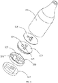
FIG. 2 is an exploded perspective view of the liquid supply ofFIG. 1 . -
FIG. 3 is a perspective view of an atomizing device, according to a second embodiment. -
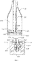
FIG. 4 is a cross-sectional view of an atomizer, including the liquid supply ofFIG. 1 and the atomizing device ofFIG. 3 , the atomizing device including a sliding block, when the liquid supply being unassembled with the atomizing device, and the sliding block being in a first position. -
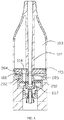
FIG. 5 is a cross-sectional view of an atomizer when the liquid supply is assembled with the atomizing device, and the sliding block being in a second position. -
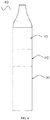
FIG. 6 is an exploded perspective view of an electronic cigarette according to a third embodiment. - It will be appreciated that for simplicity and clarity of illustration, where appropriate, reference numerals have been repeated among the different figures to indicate corresponding or analogous elements. In addition, numerous specific details are set forth in order to provide a thorough understanding of the embodiments described herein. However, it will be understood by those of ordinary skill in the art that the embodiments described herein can be practiced without these specific details. In other instances, methods, procedures and components have not been described in detail so as not to obscure the related relevant feature being described. Also, the description is not to be considered as limiting the scope of the embodiments described herein. The drawings are not necessarily to scale and the proportions of certain parts have been exaggerated to better illustrate details and features of the present disclosure.
- The disclosure is illustrated by way of example and not by way of limitation in the figures of the accompanying drawings in which like references indicate similar elements. It should be noted that references to "an" or "one" embodiment in this disclosure are not necessarily to the same embodiment, and such references mean at least one.
- Several definitions that apply throughout this disclosure will now be presented.
- The term "outside" refers to a region that is beyond the outermost confines of a physical object. The term "inside" indicates that at least a portion of a region is partially contained within a boundary formed by the object. The term "substantially" is defined to be essentially conforming to the particular dimension, shape or other word that substantially modifies, such that the component need not be exact. For example, substantially cylindrical means that the object resembles a cylinder, but can have one or more deviations from a true cylinder. The term "comprising," when utilized, means "including, but not necessarily limited to"; it specifically indicates open-ended inclusion or membership in the so-described combination, group, series and the like.
- Referring to
FIGS. 1-2 , aliquid supply 10 is shown. Theliquid supply 10 is configured (i.e., structured and arranged) for coupling with an atomizingdevice 20 to form an atomizer. Theliquid supply 10 includes ahousing 101 and a connectingend 102 at an end of thehousing 101. Thehousing 101 defines aliquid chamber 103 for storing tobacco liquid. Amouthpiece 113 is provided at the other end of thehousing 101. Anair pipe 112 is further provided in thehousing 101. Theair pipe 112 extends along an axial direction of thehousing 101, and communicates with themouthpiece 112. An annular space is formed between theair pipe 112 and thehousing 101, and serves as theliquid chamber 103. In the present embodiment, thehousing 101, themouthpiece 113 and theair pipe 112 are integrally formed. The connectingend 102 defines aliquid outlet 104. A certain mechanism is used to seal or open theliquid outlet 104, thus controlling flow of tobacco liquid in the liquid chamber. - A
sliding block 108 is arranged in the connectingend 102, and slidable between a first position and a second position (the first and second positions will be described in detail later). When thesliding block 108 is in the first position, thesliding block 108 seals theliquid outlet 104. When thesliding block 108 is in the second position, theliquid outlet 104 is opened. - The
housing 101 defines an opening at an end, and asealing element 105 is provided in the end of thehousing 101. The sealingelement 105 is made of silicone or other resilient material. Afixing plate 114 is provided on the sealingelement 105, and configured for supporting thesealing element 105. Thesealing element 105 and thefixing plate 114 are both circular in cross-section, and are arranged at an end of theair pipe 112 via central holes, thus sealing the opening of thehousing 101. Theliquid outlet 104 is defined in thesealing element 105. Quite usefully, theliquid outlet 104 deviates from acentral hole 115 of the sealingelement 105. Air can flow through thecentral hole 115. The slidingblock 108 is made of hard material, and abuts tightly against a bottom surface of the sealingelement 105. The slidingblock 108 defines a throughhole 109. When the throughhole 109 is misaligned with theliquid outlet 104, the sliding block 108 seals theliquid outlet 104; when the throughhole 109 is aligned or partially aligned with theliquid outlet 104, the slidingblock 108 opens theliquid outlet 104. - Referring to
FIG. 2 , aholder 106 and a guidingelement 107 are further provided in the connectingend 102. The slidingblock 108 is assembled in theholder 106. The guidingelement 107 is configured for guiding an engaging part 202 (as seen inFIG. 3 ) of anatomizing device 20 to move along a predetermined track. Theholder 106 and the guidingelement 107 are sequentially arranged below the sealingelement 105, and both are fixed in thehousing 101. Theholder 106 includes a rail, along which the slidingblock 108 slides along a straight line. The throughhole 109 is substantially elliptic in cross-section. A shape of the throughhole 109 is identical with that of theliquid outlet 104. The guidingelement 107 defines a run-through cavity, so that theengaging part 202 can pass through the cavity and drive the slidingblock 108 to move. - Referring to
FIG. 3 , theatomizing device 20 includes amain body 201 and theengaging part 202 at an end of themain body 201. Theengaging part 202 defines aliquid inlet 204. Theliquid inlet 204 is substantially elliptic. A shape of theliquid inlet 204 is identical with that of theliquid outlet 104. Only when theliquid outlet 104 is substantially aligned with theliquid inlet 204, tobacco liquid can flow into theatomizing device 20. Theengaging part 202 protrudes from an end surface of themain body 201, so that theengaging part 202 can insert into the cavity in the connectingend 102 to form a snap-fit connection. - Quite usefully, to achieve the snap-fit connection, two latching
parts 206 are formed at two opposite sides of theengaging part 202. The guidingelement 107 defines an insertingopening 111 and twoengaging grooves 110. In the drawings, only one engaginggroove 110 is shown (as seen inFIG. 1 ). The engaginggrooves 110 are configured for coupling with the latchingparts 206. When theliquid supply 10 is not yet connected with theatomizing device 20, the slidingblock 108 is in the first position. Theengaging part 202 is capable of sliding along a predetermined track to form the snap-fit connection with the connectingend 102, and simultaneously driving the slidingblock 108 to move from the first position to the second position, where theliquid outlet 104 is opened. When theengaging part 202 returns along the predetermined track to be detached from the connectingend 102, theengaging part 202 drives the slidingblock 108 to move to the first position where theliquid outlet 104 is sealed again. In the present embodiment, theengaging part 202 slides along a track of a straight line. - To achieve that the
engaging part 202 drives the slidingblock 108 to move when theengaging part 202 moves, a protrudingrod 203 is formed on theengaging part 202, and theliquid inlet 204 is defined in the protrudingrod 203. When theengaging part 202 is inserted into the cavity of the guidingelement 107, the latchingparts 206 are plugged into the insertingopening 111, and the protrudingrod 203 is also inserted into the throughhole 109 of the slidingblock 108. When the latchingparts 206 slide along the engaginggrooves 110, the protrudingrod 203 drives the slidingblock 108 to move together. Theengaging part 202 defines anair outlet 205. When the slidingblock 108 is in the second position, theair outlet 205 aligns with theair pipe 112. - Referring to
Figs. 4-5 , when theliquid supply 10 and theatomizing device 20 are not connected, the slidingblock 108 is in the first position, the throughhole 109 of the slidingblock 108 is misaligned with theliquid outlet 104, and the tobacco liquid is sealed. When theliquid supply 10 and theatomizing device 20 are connected with each other, the protrudingrod 203 is inserted into the throughhole 109, and an outline of theliquid supply 10 is misaligned with that of theatomizing device 20. In the present embodiment, a height of the protrudingrod 203 is equal to or slightly larger than a thickness of the slidingblock 108, and a top end of the protrudingrod 203 tightly abuts against a bottom surface of the sealingelement 105. A height of a tubular body, which defines theair outlet 205, is substantially equal to that of the protrudingrod 203. When theatomizing device 20 is moved left horizontally, the protrudingrod 203 drives the slidingblock 108 to slide to the second position. As seen inFIG. 5 , in the second position, theliquid outlet 104 is aligned with theliquid inlet 204, theair outlet 205 is in communication with theair pipe 112, and the outline of theliquid supply 10 fits well with that of theatomizing device 20. - The
atomizing device 20 further includes aliquid conducting body 207 in themain body 201 and aheating element 208 in themain body 201. Theliquid conducting body 207 may be made of glass fiber or porous ceramic. Theheating element 208 is usually a heating wire wound around theliquid conducting body 207. When the slidingblock 108 is in the second position, the tobacco liquid can flow into themain body 201 via theliquid inlet 204, and theliquid conducting body 207 conveys the tobacco liquid from theliquid inlet 204 to theheating element 208 for atomization. Theheating element 208 heats the tobacco liquid to form aerosol, and the aerosol flows into theair pipe 112 via theair outlet 205. To control a releasing speed of tobacco liquid, an annularfiber cotton layer 210 is further provided below theliquid inlet 204, and two opposite ends of the liquid conducting body contacts with thefiber cotton layer 210. Thefiber cotton layer 210 can control the tobacco liquid to release slowly to theliquid conducting body 207. Anelectrode assembly 209 is further provided at a bottom of themain body 201, and is connected to theheating element 208. Theheating element 208 is connected to a power supply via theelectrode assembly 209. - To detach the
liquid supply 10 from theatomizing device 20, the atomizing is pushed right horizontally relative to theliquid supply 10, theengaging part 202 drives the slidingblock 108 to move to the first position, where theliquid outlet 104 is misaligned with theliquid inlet 204. Accordingly, liquid leakage is avoided during the process of detaching. Meanwhile, the latchingparts 206 are disengaged from the engaginggrooves 110. In the present embodiment, the track of the sliding block and the engaging grooves are both linear, and the engaging part slides along the linear track. It is noteworthy that, in other embodiments, the engaging part may slide along a curved track relative to the liquid supply, depending on a shape of a track of the sliding block and the engaging grooves. - Referring to
FIG. 6 , anelectronic cigarette 40 includes the above atomizer and apower supply 30. The above atomizer includes theliquid supply 10 and theatomizing device 20, which will not be described below. Theliquid supply 10 is connected to one end of theatomizing device 20, and thepower supply 30 is connected to the other end of theatomizing device 20. Thepower supply 30 is configured for supplying theatomizing device 20 power. - It is understood that the above-described embodiments are intended to illustrate rather than limit the disclosure. Variations may be made to the embodiments and methods without departing from the spirit of the disclosure. Accordingly, it is appropriate that the appended claims be construed broadly and in a manner consistent with the scope of the disclosure.
Claims (10)
- An atomizer, comprising:an atomizing device comprising an engaging part; anda liquid supply detachably connected with the atomizing device, the liquid supply comprising a liquid chamber, the liquid chamber being configured for storing tobacco liquid, the liquid supply comprising a connecting end and a liquid outlet defined in the connecting end, the engaging part matching with the connecting end, the engaging part defining a liquid inlet through which tobacco liquid can flow into the atomizing device;wherein the liquid supply further comprises a sliding block slidable between a first position and a second position, when the sliding block is in the first position, the sliding block seals the liquid outlet, when the sliding block is in the second position,the liquid outlet is opened; the engaging part is capable of sliding along a predetermined track to form a snap-fit connection with the connecting end, andsimultaneously driving the sliding block to move from the first position to the second position; when the engaging part returns along the predetermined track to be detached from the connecting end, the engaging part is capable of driving the sliding block to move to the first position.
- The atomizer in accordance with claim 1, wherein the engaging part slides relative to the liquid supply along a linear track or a curved track.
- The atomizer in accordance with claim 1, wherein the liquid supply further comprises a housing and a sealing element, the housing has an opening at an end, the sealing element is arranged in an end of the housing with the opening, the sealing element is configured for sealing the liquid chamber, the liquid outlet is defined in the sealing element, and the sliding block slides along an end surface of the sealing element.
- The atomizer in accordance with claim 3, wherein the sealing element is substantially circular in cross-section, and the liquid outlet deviates from a center of the sealing element.
- The atomizer in accordance with claim 1, wherein the liquid supply further comprises a holder and a guiding element in the connecting end, the sliding block is assembled in the holder, and the guiding element is configured for guiding the engaging part to move along the predetermined track.
- The atomizer in accordance with claim 5, wherein the atomizing device comprises two latching parts on the engaging parts, the guiding element defines an inserting opening and two engaging grooves, the two latching parts are inserted into the guiding element via the inserting opening, and the engaging grooves are configured for coupling with the latching parts.
- The atomizer in accordance with claim 1, wherein the atomizing device comprises a protruding rod formed on the engaging part, the liquid inlet is defined in the protruding rod; the sliding block defines a through hole, the protruding rod is capable of inserting into the through hole and driving the sliding block to move.
- The atomizer in accordance with claim 1, wherein the atomizing device comprises a main body, a liquid conducting body in the main body and a heating element in the main body, the engaging part is arranged at an end of the main body, the liquid conducting body is configured for conveying tobacco liquid flowed from the liquid inlet to the heating element for atomization.
- An electronic cigarette, comprising:an atomizer according to any of claims 1-8; anda power supply, the liquid supply being connected to a first end of the atomizing device, and the power supply being connected to an opposite second end of the atomizing device, the power supply being configured for supplying the atomizing device power.
- A liquid supply, comprising:a housing defining a liquid chamber, the housing having a connecting end at an end thereof, the connecting end defining a liquid outlet;wherein the liquid supply further comprises a sliding block slidable between a first position and a second position, when the sliding block is in the first position, the sliding block seals the liquid outlet; when the sliding block is in the second position, the liquid outlet is opened.
Applications Claiming Priority (1)
| Application Number | Priority Date | Filing Date | Title |
|---|---|---|---|
| CN201520951321.XU CN205197001U (en) | 2015-11-25 | 2015-11-25 | Stock solution device that split type atomizer, electron cigarette and being convenient for was changed |
Publications (2)
| Publication Number | Publication Date |
|---|---|
| EP3138427A1 true EP3138427A1 (en) | 2017-03-08 |
| EP3138427B1 EP3138427B1 (en) | 2020-09-02 |
Family
ID=55834760
Family Applications (1)
| Application Number | Title | Priority Date | Filing Date |
|---|---|---|---|
| EP16200372.7A Active EP3138427B1 (en) | 2015-11-25 | 2016-11-24 | Liquid supply, atomizer and electronic cigarette having same |
Country Status (3)
| Country | Link |
|---|---|
| US (1) | US10791759B2 (en) |
| EP (1) | EP3138427B1 (en) |
| CN (1) | CN205197001U (en) |
Cited By (4)
| Publication number | Priority date | Publication date | Assignee | Title |
|---|---|---|---|---|
| EP3741237A1 (en) * | 2019-05-24 | 2020-11-25 | Nerudia Limited | Aerosol delivery device |
| EP4111878A4 (en) * | 2020-02-25 | 2024-04-10 | Changzhou Patent Electronic Technology Co., Ltd | ATOMIZER AND AEROSOL GENERATING DEVICE |
| US12048329B2 (en) | 2018-09-14 | 2024-07-30 | Imperial Tobacco Limited | Consumable for a smoking substitute device |
| US12082611B2 (en) | 2019-05-24 | 2024-09-10 | Imperial Tobacco Limited | Aerosol delivery device |
Families Citing this family (44)
| Publication number | Priority date | Publication date | Assignee | Title |
|---|---|---|---|---|
| US10244793B2 (en) | 2005-07-19 | 2019-04-02 | Juul Labs, Inc. | Devices for vaporization of a substance |
| US10279934B2 (en) | 2013-03-15 | 2019-05-07 | Juul Labs, Inc. | Fillable vaporizer cartridge and method of filling |
| US10076139B2 (en) | 2013-12-23 | 2018-09-18 | Juul Labs, Inc. | Vaporizer apparatus |
| US10159282B2 (en) | 2013-12-23 | 2018-12-25 | Juul Labs, Inc. | Cartridge for use with a vaporizer device |
| US20160366947A1 (en) | 2013-12-23 | 2016-12-22 | James Monsees | Vaporizer apparatus |
| USD842536S1 (en) | 2016-07-28 | 2019-03-05 | Juul Labs, Inc. | Vaporizer cartridge |
| US10058129B2 (en) | 2013-12-23 | 2018-08-28 | Juul Labs, Inc. | Vaporization device systems and methods |
| KR102721939B1 (en) | 2013-12-23 | 2024-10-25 | 쥴 랩스, 인크. | Vaporization device systems and methods |
| USD825102S1 (en) | 2016-07-28 | 2018-08-07 | Juul Labs, Inc. | Vaporizer device with cartridge |
| US10004263B2 (en) * | 2014-03-07 | 2018-06-26 | Huizhou Kimree Technology Co., Ltd. Shenzhen Branch | Electronic cigarette provided with accumulated E-liquid removal function, and method therefor |
| KR20250012730A (en) | 2014-12-05 | 2025-01-24 | 쥴 랩스, 인크. | Calibrated dose control |
| US9999255B2 (en) * | 2016-01-21 | 2018-06-19 | Shenzhen First Union Technology Co., Ltd. | Electronic cigarette with a blocking module |
| MX377347B (en) | 2016-02-11 | 2025-03-07 | Juul Labs Inc | Fillable vaporizer cartridge and method of filling |
| MX388616B (en) | 2016-02-11 | 2025-03-20 | Juul Labs Inc | SECURE FITTING CARTRIDGES FOR VAPORIZING DEVICES |
| US10405582B2 (en) | 2016-03-10 | 2019-09-10 | Pax Labs, Inc. | Vaporization device with lip sensing |
| CA3011956A1 (en) * | 2016-03-31 | 2017-10-05 | Philip Morris Products S.A. | Aerosol generating system with separate capsule and vaporizing unit |
| USD849996S1 (en) | 2016-06-16 | 2019-05-28 | Pax Labs, Inc. | Vaporizer cartridge |
| USD836541S1 (en) | 2016-06-23 | 2018-12-25 | Pax Labs, Inc. | Charging device |
| USD851830S1 (en) | 2016-06-23 | 2019-06-18 | Pax Labs, Inc. | Combined vaporizer tamp and pick tool |
| US9795170B1 (en) * | 2016-08-07 | 2017-10-24 | Xiaochun Zhu | E-liquid separation mechanism and electronic cigarette having the same |
| CN106108120B (en) * | 2016-08-12 | 2018-11-23 | 湖北中烟工业有限责任公司 | A kind of electronic smoke atomizer of achievable automatic locking oil-leakage-prevention function |
| WO2018102696A1 (en) | 2016-12-02 | 2018-06-07 | Vmr Products Llc | Vaporizer |
| WO2018111843A1 (en) | 2016-12-12 | 2018-06-21 | Vmr Products Llc | Vaporizer cartridge |
| US11160940B2 (en) * | 2017-06-02 | 2021-11-02 | Jt International S.A. | Aerosol generation system with replaceable atomizer |
| USD887632S1 (en) | 2017-09-14 | 2020-06-16 | Pax Labs, Inc. | Vaporizer cartridge |
| CN108451038A (en) * | 2018-03-30 | 2018-08-28 | 深圳麦克韦尔股份有限公司 | The assemble method of electronic cigarette and its atomising device and atomising device |
| DE102018206647A1 (en) * | 2018-04-27 | 2019-10-31 | Hauni Maschinenbau Gmbh | Evaporator insert, evaporator tank unit for an inhaler, inhaler, and manufacturing process |
| CN109303355A (en) * | 2018-11-02 | 2019-02-05 | 深圳市合元科技有限公司 | Atomizer and electronic cigarette with detachable atomizing core |
| KR102817701B1 (en) | 2018-11-05 | 2025-06-09 | 쥴 랩스, 인크. | Cartridge for vaporizer device |
| CN109602090B (en) * | 2018-12-19 | 2022-11-15 | 深圳市新宜康科技股份有限公司 | Aerial fog generator of high-end lock catch and release mechanism and control method thereof |
| US20200245695A1 (en) * | 2019-02-03 | 2020-08-06 | Avanzato Technology Corp. | Vaporization device having a wick and coil assembly |
| GB201903538D0 (en) | 2019-03-15 | 2019-05-01 | Nicoventures Trading Ltd | Atomiser enclosure for a vapour provision system |
| GB201903539D0 (en) * | 2019-03-15 | 2019-05-01 | Nicoventures Trading Ltd | Atomiser for a vapour provision system |
| GB201903537D0 (en) * | 2019-03-15 | 2019-05-01 | Nicoventures Trading Ltd | Flow directing member for a vapour provision system |
| CN112144228B (en) * | 2019-06-28 | 2023-01-06 | 青岛海尔洗涤电器有限公司 | Atomization device for clothes treatment equipment and clothes treatment equipment |
| GB201912477D0 (en) | 2019-08-30 | 2019-10-16 | Nicoventures Trading Ltd | Aerosol provision systems |
| GB201914831D0 (en) * | 2019-10-14 | 2019-11-27 | Nicoventures Trading Ltd | Aerosol provision systems |
| CN111820457A (en) * | 2020-05-27 | 2020-10-27 | 深圳市吉迩科技有限公司 | Oil core separation structure, oil core separation method and aerosol generating device |
| CN112237300A (en) * | 2020-11-24 | 2021-01-19 | 凡品思(深圳)科技有限公司 | Atomizing device and electron cigarette |
| CN114098160B (en) * | 2021-11-29 | 2023-12-22 | 深圳市真味生物科技有限公司 | Essence spices storage facilities for electronic atomizer convenient to storage |
| CN222031475U (en) * | 2024-02-04 | 2024-11-22 | 派克斯创新(深圳)科技有限公司 | Electronic cigarette component |
| EP4595793A1 (en) * | 2024-02-04 | 2025-08-06 | PAX Innovations (Shenzhen) Limited | Electronic cigarette assembly with replaceable atomizing core |
| EP4606236A1 (en) * | 2024-02-23 | 2025-08-27 | JT International SA | Aerosol generating systems and cartomizers therefor |
| CN121489188A (en) * | 2024-08-09 | 2026-02-10 | 深圳市合元科技有限公司 | Aerosol matrix storage device and aerosol generation apparatus including the aerosol matrix storage device |
Citations (2)
| Publication number | Priority date | Publication date | Assignee | Title |
|---|---|---|---|---|
| CN104738816A (en) * | 2015-02-04 | 2015-07-01 | 深圳市合元科技有限公司 | Atomizer, electronic cigarette and liquid storage device suitable for being replaced |
| CN204670386U (en) * | 2015-04-29 | 2015-09-30 | 深圳市合元科技有限公司 | Atomizer and use the electronic cigarette of this atomizer |
Family Cites Families (17)
| Publication number | Priority date | Publication date | Assignee | Title |
|---|---|---|---|---|
| US2863676A (en) * | 1956-03-05 | 1958-12-09 | Aeroquip Corp | Multiple breakaway slide seal coupling |
| US3425414A (en) * | 1965-05-28 | 1969-02-04 | William J La Roche | Inhalant dispenser |
| GB0712305D0 (en) * | 2007-06-25 | 2007-08-01 | Kind Group Ltd | A system comprising a simulated cigarette device and a refill unit |
| WO2009001082A1 (en) * | 2007-06-25 | 2008-12-31 | Kind Consumer Limited | A simulated cigarette device |
| CN103732280B (en) * | 2011-08-19 | 2016-01-06 | 日本烟草产业株式会社 | Aerosol Aspirator |
| CN103960781A (en) * | 2013-09-29 | 2014-08-06 | 深圳市麦克韦尔科技有限公司 | Electronic cigarette |
| WO2015096107A1 (en) * | 2013-12-26 | 2015-07-02 | 吉瑞高新科技股份有限公司 | Atomization apparatus, electronic cigarette, and assembly method therefor |
| CN103750570B (en) * | 2014-01-15 | 2016-02-24 | 林光榕 | Facilitate the electronic cigarette of fluid injection and manufacture method and electrolyte filling method |
| WO2015180167A1 (en) * | 2014-05-30 | 2015-12-03 | 深圳麦克韦尔股份有限公司 | Electronic cigarette and atomizer thereof |
| CN104366695B (en) * | 2014-10-29 | 2017-12-08 | 深圳麦克韦尔股份有限公司 | Atomizer, atomizing component and inhalator |
| CN204232301U (en) * | 2014-11-13 | 2015-04-01 | 深圳市合元科技有限公司 | Atomizer and electronic cigarette |
| JP6710684B2 (en) * | 2014-11-17 | 2020-06-17 | マクニール アーベーMcneil Ab | Disposable cartridge for use in electronic nicotine delivery system |
| TR201910352T4 (en) * | 2014-11-17 | 2019-07-22 | Mcneil Ab | Electronic nicotine delivery system. |
| US20160150828A1 (en) * | 2014-12-02 | 2016-06-02 | Gabriel Marc Goldstein | Vaporizing reservoir |
| WO2016172847A1 (en) * | 2015-04-28 | 2016-11-03 | 深圳麦克韦尔股份有限公司 | Inhaler and atomization component thereof |
| US10015989B2 (en) * | 2016-01-27 | 2018-07-10 | Rai Strategic Holdings, Inc. | One-way valve for refilling an aerosol delivery device |
| US10085485B2 (en) * | 2016-07-06 | 2018-10-02 | Rai Strategic Holdings, Inc. | Aerosol delivery device with a reservoir housing and a vaporizer assembly |
-
2015
- 2015-11-25 CN CN201520951321.XU patent/CN205197001U/en not_active Expired - Lifetime
-
2016
- 2016-11-23 US US15/360,019 patent/US10791759B2/en active Active
- 2016-11-24 EP EP16200372.7A patent/EP3138427B1/en active Active
Patent Citations (4)
| Publication number | Priority date | Publication date | Assignee | Title |
|---|---|---|---|---|
| CN104738816A (en) * | 2015-02-04 | 2015-07-01 | 深圳市合元科技有限公司 | Atomizer, electronic cigarette and liquid storage device suitable for being replaced |
| EP3053459A2 (en) * | 2015-02-04 | 2016-08-10 | Shenzhen First Union Technology Co., Ltd. | Liquid supply, atomizer and electronic cigarette having same |
| CN204670386U (en) * | 2015-04-29 | 2015-09-30 | 深圳市合元科技有限公司 | Atomizer and use the electronic cigarette of this atomizer |
| EP3025602A2 (en) * | 2015-04-29 | 2016-06-01 | Shenzhen First Union Technology Co., Ltd. | Atomizer and electronic cigarette having same |
Cited By (4)
| Publication number | Priority date | Publication date | Assignee | Title |
|---|---|---|---|---|
| US12048329B2 (en) | 2018-09-14 | 2024-07-30 | Imperial Tobacco Limited | Consumable for a smoking substitute device |
| EP3741237A1 (en) * | 2019-05-24 | 2020-11-25 | Nerudia Limited | Aerosol delivery device |
| US12082611B2 (en) | 2019-05-24 | 2024-09-10 | Imperial Tobacco Limited | Aerosol delivery device |
| EP4111878A4 (en) * | 2020-02-25 | 2024-04-10 | Changzhou Patent Electronic Technology Co., Ltd | ATOMIZER AND AEROSOL GENERATING DEVICE |
Also Published As
| Publication number | Publication date |
|---|---|
| CN205197001U (en) | 2016-05-04 |
| US10791759B2 (en) | 2020-10-06 |
| EP3138427B1 (en) | 2020-09-02 |
| US20170071260A1 (en) | 2017-03-16 |
Similar Documents
| Publication | Publication Date | Title |
|---|---|---|
| EP3138427B1 (en) | Liquid supply, atomizer and electronic cigarette having same | |
| EP3135140B1 (en) | Liquid supply, atomizer and electronic cigarette having same | |
| EP3025602B1 (en) | Atomizer and electronic cigarette having same | |
| EP3040095B1 (en) | Atomizer and electronic cigarette having same | |
| US9848649B2 (en) | Atomizer and electronic cigarette having same | |
| EP3097804B1 (en) | Atomizer and electronic cigarette having same | |
| EP3020290B1 (en) | Atomizer and electronic cigarette having same | |
| US9993028B2 (en) | Atomizer having replaceable atomizing core and electronic cigarette having same | |
| EP3053459B1 (en) | Atomizer and electronic cigarette having same | |
| EP2965641B1 (en) | Atomizing head, atomizer and electronic cigarette having same | |
| US9894934B2 (en) | Aerosol generating device and aerosol inhalation device having same | |
| EP2946679A1 (en) | Atomizer and electronic cigarette having same | |
| CN107205475B (en) | Electronic cigarette and method for preventing smoke oil leakage thereof | |
| EP2984952A1 (en) | Atomizer and electronic cigarette having same | |
| CN108208935B (en) | Atomizer and electronic cigarette | |
| US20170303598A1 (en) | Heating device for heating cigarette | |
| WO2023082674A1 (en) | Aerosol generating apparatus and atomizer thereof | |
| CN110856554B (en) | Liquid storage component, atomizer and electronic cigarette | |
| CN205813573U (en) | Electronic cigarette and nebulizer thereof | |
| CN214677559U (en) | Atomizing storehouse and atomizer | |
| WO2023125859A1 (en) | Atomizer and electronic atomization device | |
| CN209420958U (en) | Atomizers and Electronic Cigarettes | |
| EP4430970A1 (en) | Atomization device, liquid storage device, and atomization assembly | |
| CN207341173U (en) | Cover assembly, atomising device and electronic cigarette |
Legal Events
| Date | Code | Title | Description |
|---|---|---|---|
| PUAI | Public reference made under article 153(3) epc to a published international application that has entered the european phase |
Free format text: ORIGINAL CODE: 0009012 |
|
| STAA | Information on the status of an ep patent application or granted ep patent |
Free format text: STATUS: THE APPLICATION HAS BEEN PUBLISHED |
|
| STAA | Information on the status of an ep patent application or granted ep patent |
Free format text: STATUS: REQUEST FOR EXAMINATION WAS MADE |
|
| AK | Designated contracting states |
Kind code of ref document: A1 Designated state(s): AL AT BE BG CH CY CZ DE DK EE ES FI FR GB GR HR HU IE IS IT LI LT LU LV MC MK MT NL NO PL PT RO RS SE SI SK SM TR |
|
| AX | Request for extension of the european patent |
Extension state: BA ME |
|
| 17P | Request for examination filed |
Effective date: 20170221 |
|
| RBV | Designated contracting states (corrected) |
Designated state(s): AL AT BE BG CH CY CZ DE DK EE ES FI FR GB GR HR HU IE IS IT LI LT LU LV MC MK MT NL NO PL PT RO RS SE SI SK SM TR |
|
| STAA | Information on the status of an ep patent application or granted ep patent |
Free format text: STATUS: EXAMINATION IS IN PROGRESS |
|
| 17Q | First examination report despatched |
Effective date: 20180209 |
|
| REG | Reference to a national code |
Ref country code: DE Ref legal event code: R079 Ref document number: 602016043106 Country of ref document: DE Free format text: PREVIOUS MAIN CLASS: A24F0047000000 Ipc: A24F0040485000 |
|
| GRAP | Despatch of communication of intention to grant a patent |
Free format text: ORIGINAL CODE: EPIDOSNIGR1 |
|
| STAA | Information on the status of an ep patent application or granted ep patent |
Free format text: STATUS: GRANT OF PATENT IS INTENDED |
|
| RIC1 | Information provided on ipc code assigned before grant |
Ipc: A24F 40/485 20200101AFI20200423BHEP |
|
| INTG | Intention to grant announced |
Effective date: 20200519 |
|
| GRAS | Grant fee paid |
Free format text: ORIGINAL CODE: EPIDOSNIGR3 |
|
| GRAA | (expected) grant |
Free format text: ORIGINAL CODE: 0009210 |
|
| STAA | Information on the status of an ep patent application or granted ep patent |
Free format text: STATUS: THE PATENT HAS BEEN GRANTED |
|
| AK | Designated contracting states |
Kind code of ref document: B1 Designated state(s): AL AT BE BG CH CY CZ DE DK EE ES FI FR GB GR HR HU IE IS IT LI LT LU LV MC MK MT NL NO PL PT RO RS SE SI SK SM TR |
|
| REG | Reference to a national code |
Ref country code: GB Ref legal event code: FG4D |
|
| REG | Reference to a national code |
Ref country code: AT Ref legal event code: REF Ref document number: 1307758 Country of ref document: AT Kind code of ref document: T Effective date: 20200915 Ref country code: CH Ref legal event code: EP |
|
| REG | Reference to a national code |
Ref country code: DE Ref legal event code: R096 Ref document number: 602016043106 Country of ref document: DE |
|
| REG | Reference to a national code |
Ref country code: IE Ref legal event code: FG4D |
|
| REG | Reference to a national code |
Ref country code: LT Ref legal event code: MG4D |
|
| PG25 | Lapsed in a contracting state [announced via postgrant information from national office to epo] |
Ref country code: FI Free format text: LAPSE BECAUSE OF FAILURE TO SUBMIT A TRANSLATION OF THE DESCRIPTION OR TO PAY THE FEE WITHIN THE PRESCRIBED TIME-LIMIT Effective date: 20200902 Ref country code: LT Free format text: LAPSE BECAUSE OF FAILURE TO SUBMIT A TRANSLATION OF THE DESCRIPTION OR TO PAY THE FEE WITHIN THE PRESCRIBED TIME-LIMIT Effective date: 20200902 Ref country code: BG Free format text: LAPSE BECAUSE OF FAILURE TO SUBMIT A TRANSLATION OF THE DESCRIPTION OR TO PAY THE FEE WITHIN THE PRESCRIBED TIME-LIMIT Effective date: 20201202 Ref country code: GR Free format text: LAPSE BECAUSE OF FAILURE TO SUBMIT A TRANSLATION OF THE DESCRIPTION OR TO PAY THE FEE WITHIN THE PRESCRIBED TIME-LIMIT Effective date: 20201203 Ref country code: NO Free format text: LAPSE BECAUSE OF FAILURE TO SUBMIT A TRANSLATION OF THE DESCRIPTION OR TO PAY THE FEE WITHIN THE PRESCRIBED TIME-LIMIT Effective date: 20201202 Ref country code: HR Free format text: LAPSE BECAUSE OF FAILURE TO SUBMIT A TRANSLATION OF THE DESCRIPTION OR TO PAY THE FEE WITHIN THE PRESCRIBED TIME-LIMIT Effective date: 20200902 Ref country code: SE Free format text: LAPSE BECAUSE OF FAILURE TO SUBMIT A TRANSLATION OF THE DESCRIPTION OR TO PAY THE FEE WITHIN THE PRESCRIBED TIME-LIMIT Effective date: 20200902 |
|
| REG | Reference to a national code |
Ref country code: NL Ref legal event code: MP Effective date: 20200902 |
|
| REG | Reference to a national code |
Ref country code: AT Ref legal event code: MK05 Ref document number: 1307758 Country of ref document: AT Kind code of ref document: T Effective date: 20200902 |
|
| PG25 | Lapsed in a contracting state [announced via postgrant information from national office to epo] |
Ref country code: PL Free format text: LAPSE BECAUSE OF FAILURE TO SUBMIT A TRANSLATION OF THE DESCRIPTION OR TO PAY THE FEE WITHIN THE PRESCRIBED TIME-LIMIT Effective date: 20200902 Ref country code: LV Free format text: LAPSE BECAUSE OF FAILURE TO SUBMIT A TRANSLATION OF THE DESCRIPTION OR TO PAY THE FEE WITHIN THE PRESCRIBED TIME-LIMIT Effective date: 20200902 Ref country code: RS Free format text: LAPSE BECAUSE OF FAILURE TO SUBMIT A TRANSLATION OF THE DESCRIPTION OR TO PAY THE FEE WITHIN THE PRESCRIBED TIME-LIMIT Effective date: 20200902 |
|
| PG25 | Lapsed in a contracting state [announced via postgrant information from national office to epo] |
Ref country code: EE Free format text: LAPSE BECAUSE OF FAILURE TO SUBMIT A TRANSLATION OF THE DESCRIPTION OR TO PAY THE FEE WITHIN THE PRESCRIBED TIME-LIMIT Effective date: 20200902 Ref country code: NL Free format text: LAPSE BECAUSE OF FAILURE TO SUBMIT A TRANSLATION OF THE DESCRIPTION OR TO PAY THE FEE WITHIN THE PRESCRIBED TIME-LIMIT Effective date: 20200902 Ref country code: PT Free format text: LAPSE BECAUSE OF FAILURE TO SUBMIT A TRANSLATION OF THE DESCRIPTION OR TO PAY THE FEE WITHIN THE PRESCRIBED TIME-LIMIT Effective date: 20210104 Ref country code: SM Free format text: LAPSE BECAUSE OF FAILURE TO SUBMIT A TRANSLATION OF THE DESCRIPTION OR TO PAY THE FEE WITHIN THE PRESCRIBED TIME-LIMIT Effective date: 20200902 Ref country code: RO Free format text: LAPSE BECAUSE OF FAILURE TO SUBMIT A TRANSLATION OF THE DESCRIPTION OR TO PAY THE FEE WITHIN THE PRESCRIBED TIME-LIMIT Effective date: 20200902 Ref country code: CZ Free format text: LAPSE BECAUSE OF FAILURE TO SUBMIT A TRANSLATION OF THE DESCRIPTION OR TO PAY THE FEE WITHIN THE PRESCRIBED TIME-LIMIT Effective date: 20200902 |
|
| PG25 | Lapsed in a contracting state [announced via postgrant information from national office to epo] |
Ref country code: ES Free format text: LAPSE BECAUSE OF FAILURE TO SUBMIT A TRANSLATION OF THE DESCRIPTION OR TO PAY THE FEE WITHIN THE PRESCRIBED TIME-LIMIT Effective date: 20200902 Ref country code: AT Free format text: LAPSE BECAUSE OF FAILURE TO SUBMIT A TRANSLATION OF THE DESCRIPTION OR TO PAY THE FEE WITHIN THE PRESCRIBED TIME-LIMIT Effective date: 20200902 Ref country code: AL Free format text: LAPSE BECAUSE OF FAILURE TO SUBMIT A TRANSLATION OF THE DESCRIPTION OR TO PAY THE FEE WITHIN THE PRESCRIBED TIME-LIMIT Effective date: 20200902 Ref country code: IS Free format text: LAPSE BECAUSE OF FAILURE TO SUBMIT A TRANSLATION OF THE DESCRIPTION OR TO PAY THE FEE WITHIN THE PRESCRIBED TIME-LIMIT Effective date: 20210102 |
|
| REG | Reference to a national code |
Ref country code: DE Ref legal event code: R097 Ref document number: 602016043106 Country of ref document: DE |
|
| PG25 | Lapsed in a contracting state [announced via postgrant information from national office to epo] |
Ref country code: MC Free format text: LAPSE BECAUSE OF FAILURE TO SUBMIT A TRANSLATION OF THE DESCRIPTION OR TO PAY THE FEE WITHIN THE PRESCRIBED TIME-LIMIT Effective date: 20200902 Ref country code: SK Free format text: LAPSE BECAUSE OF FAILURE TO SUBMIT A TRANSLATION OF THE DESCRIPTION OR TO PAY THE FEE WITHIN THE PRESCRIBED TIME-LIMIT Effective date: 20200902 |
|
| REG | Reference to a national code |
Ref country code: CH Ref legal event code: PL |
|
| PLBE | No opposition filed within time limit |
Free format text: ORIGINAL CODE: 0009261 |
|
| STAA | Information on the status of an ep patent application or granted ep patent |
Free format text: STATUS: NO OPPOSITION FILED WITHIN TIME LIMIT |
|
| PG25 | Lapsed in a contracting state [announced via postgrant information from national office to epo] |
Ref country code: LU Free format text: LAPSE BECAUSE OF NON-PAYMENT OF DUE FEES Effective date: 20201124 |
|
| 26N | No opposition filed |
Effective date: 20210603 |
|
| REG | Reference to a national code |
Ref country code: BE Ref legal event code: MM Effective date: 20201130 |
|
| PG25 | Lapsed in a contracting state [announced via postgrant information from national office to epo] |
Ref country code: SI Free format text: LAPSE BECAUSE OF FAILURE TO SUBMIT A TRANSLATION OF THE DESCRIPTION OR TO PAY THE FEE WITHIN THE PRESCRIBED TIME-LIMIT Effective date: 20200902 Ref country code: LI Free format text: LAPSE BECAUSE OF NON-PAYMENT OF DUE FEES Effective date: 20201130 Ref country code: CH Free format text: LAPSE BECAUSE OF NON-PAYMENT OF DUE FEES Effective date: 20201130 Ref country code: DK Free format text: LAPSE BECAUSE OF FAILURE TO SUBMIT A TRANSLATION OF THE DESCRIPTION OR TO PAY THE FEE WITHIN THE PRESCRIBED TIME-LIMIT Effective date: 20200902 |
|
| PG25 | Lapsed in a contracting state [announced via postgrant information from national office to epo] |
Ref country code: IE Free format text: LAPSE BECAUSE OF NON-PAYMENT OF DUE FEES Effective date: 20201124 Ref country code: IT Free format text: LAPSE BECAUSE OF FAILURE TO SUBMIT A TRANSLATION OF THE DESCRIPTION OR TO PAY THE FEE WITHIN THE PRESCRIBED TIME-LIMIT Effective date: 20200902 |
|
| PG25 | Lapsed in a contracting state [announced via postgrant information from national office to epo] |
Ref country code: TR Free format text: LAPSE BECAUSE OF FAILURE TO SUBMIT A TRANSLATION OF THE DESCRIPTION OR TO PAY THE FEE WITHIN THE PRESCRIBED TIME-LIMIT Effective date: 20200902 Ref country code: MT Free format text: LAPSE BECAUSE OF FAILURE TO SUBMIT A TRANSLATION OF THE DESCRIPTION OR TO PAY THE FEE WITHIN THE PRESCRIBED TIME-LIMIT Effective date: 20200902 Ref country code: CY Free format text: LAPSE BECAUSE OF FAILURE TO SUBMIT A TRANSLATION OF THE DESCRIPTION OR TO PAY THE FEE WITHIN THE PRESCRIBED TIME-LIMIT Effective date: 20200902 |
|
| PG25 | Lapsed in a contracting state [announced via postgrant information from national office to epo] |
Ref country code: MK Free format text: LAPSE BECAUSE OF FAILURE TO SUBMIT A TRANSLATION OF THE DESCRIPTION OR TO PAY THE FEE WITHIN THE PRESCRIBED TIME-LIMIT Effective date: 20200902 |
|
| PG25 | Lapsed in a contracting state [announced via postgrant information from national office to epo] |
Ref country code: BE Free format text: LAPSE BECAUSE OF NON-PAYMENT OF DUE FEES Effective date: 20201130 |
|
| P01 | Opt-out of the competence of the unified patent court (upc) registered |
Free format text: CASE NUMBER: APP_8820/2025 Effective date: 20250220 |
|
| PGFP | Annual fee paid to national office [announced via postgrant information from national office to epo] |
Ref country code: DE Payment date: 20251117 Year of fee payment: 10 |
|
| PGFP | Annual fee paid to national office [announced via postgrant information from national office to epo] |
Ref country code: GB Payment date: 20251126 Year of fee payment: 10 |
|
| PGFP | Annual fee paid to national office [announced via postgrant information from national office to epo] |
Ref country code: FR Payment date: 20251127 Year of fee payment: 10 |