EP3138348B1 - Multiple bssid procedure with tim encoding - Google Patents
Multiple bssid procedure with tim encoding Download PDFInfo
- Publication number
- EP3138348B1 EP3138348B1 EP15715946.8A EP15715946A EP3138348B1 EP 3138348 B1 EP3138348 B1 EP 3138348B1 EP 15715946 A EP15715946 A EP 15715946A EP 3138348 B1 EP3138348 B1 EP 3138348B1
- Authority
- EP
- European Patent Office
- Prior art keywords
- subfield
- aid
- identifier
- individual bss
- bits
- Prior art date
- Legal status (The legal status is an assumption and is not a legal conclusion. Google has not performed a legal analysis and makes no representation as to the accuracy of the status listed.)
- Active
Links
Images


Classifications
-
- H—ELECTRICITY
- H04—ELECTRIC COMMUNICATION TECHNIQUE
- H04W—WIRELESS COMMUNICATION NETWORKS
- H04W8/00—Network data management
- H04W8/26—Network addressing or numbering for mobility support
-
- H—ELECTRICITY
- H04—ELECTRIC COMMUNICATION TECHNIQUE
- H04W—WIRELESS COMMUNICATION NETWORKS
- H04W28/00—Network traffic management; Network resource management
- H04W28/02—Traffic management, e.g. flow control or congestion control
-
- H—ELECTRICITY
- H04—ELECTRIC COMMUNICATION TECHNIQUE
- H04W—WIRELESS COMMUNICATION NETWORKS
- H04W4/00—Services specially adapted for wireless communication networks; Facilities therefor
-
- H—ELECTRICITY
- H04—ELECTRIC COMMUNICATION TECHNIQUE
- H04W—WIRELESS COMMUNICATION NETWORKS
- H04W4/00—Services specially adapted for wireless communication networks; Facilities therefor
- H04W4/06—Selective distribution of broadcast services, e.g. multimedia broadcast multicast service [MBMS]; Services to user groups; One-way selective calling services
-
- H—ELECTRICITY
- H04—ELECTRIC COMMUNICATION TECHNIQUE
- H04W—WIRELESS COMMUNICATION NETWORKS
- H04W74/00—Wireless channel access, e.g. scheduled or random access
- H04W74/002—Transmission of channel access control information
- H04W74/006—Transmission of channel access control information in the downlink, i.e. towards the terminal
-
- H—ELECTRICITY
- H04—ELECTRIC COMMUNICATION TECHNIQUE
- H04W—WIRELESS COMMUNICATION NETWORKS
- H04W72/00—Local resource management
- H04W72/30—Resource management for broadcast services
Definitions
- Certain aspects of the present disclosure generally relate to wireless communications and, more particularly, to multiple BSSID with TIM encoding.
- Wireless communication networks are widely deployed to provide various communication services such as voice, video, packet data, messaging, broadcast, etc. These wireless networks may be multiple-access networks capable of supporting multiple users by sharing the available network resources. Examples of such multiple-access networks include Code Division Multiple Access (CDMA) networks, Time Division Multiple Access (TDMA) networks, Frequency Division Multiple Access (FDMA) networks, Orthogonal FDMA (OFDMA) networks, and Single-Carrier FDMA (SC-FDMA) networks.
- CDMA Code Division Multiple Access
- TDMA Time Division Multiple Access
- FDMA Frequency Division Multiple Access
- OFDMA Orthogonal FDMA
- SC-FDMA Single-Carrier FDMA
- sub-1-GHz frequency range e.g., operating in the 902 - 928 MHz range in the United States
- IEEE 802.11ah task force the Institute of Electrical and Electronics Engineers 802.11ah task force. This development is driven by the desire to utilize a frequency range that has greater wireless range than other IEEE 802.11 groups and has lower obstruction losses.
- US 2009/016306 A1 discloses a method for communicating data comprising generating a traffic indication virtual bitmap based on the presence of stored data that is pending transmission via a wireless communication medium, and generating a partial virtual bitmap based on said generated traffic indication virtual bitmap, wherein said partial virtual bitmap comprises a first segment from said generated traffic indication virtual bitmap and a second segment from said generated traffic indication virtual bitmap.
- the apparatus typically includes a processing system configured to generate a frame with an information element (IE) having a partial virtual bitmap field that indicates one or more basic service sets (BSSs) that have buffered group-cast traffic, wherein the partial virtual bitmap field comprises at least one encoded subfield that identifies at least one individual BSS having buffered group-cast traffic using one or more bits of an association identification or assigned identification (AID) of the individual BSS and an interface for outputting a frame containing the IE for transmission.
- IE information element
- BSSs basic service sets
- AID association identification
- the apparatus typically includes an interface for receiving a frame containing an information element (IE) and a processing system configured to determine the presence of buffered group-cast traffic for the apparatus based on a partial virtual bitmap field in the IE that indicates one or more basic service sets (BSSs) that have buffered group-cast traffic, wherein the bitmap field comprises at least one encoded subfield that identifies at least one individual BSS having buffered group-cast traffic using one or more bits of an association identification or assigned identification (AID) of the individual BSS.
- IE information element
- BSSs basic service sets
- Certain aspects of the present disclosure provide a method for wireless communications by an apparatus.
- the method typically includes generating, at an apparatus, a frame with an information element (IE) having a partial virtual bitmap field that indicates zero or more basic service sets (BSSs) that have buffered group-cast traffic, wherein the partial virtual bitmap field comprises at least one encoded subfield that identifies at least one individual BSS having buffered group-cast traffic using one or more bits of an identifier of the individual BSS, and outputting the frame containing the IE for transmission.
- IE information element
- BSSs basic service sets
- Certain aspects of the present disclosure provide a method for wireless communications by an apparatus.
- the method typically includes receiving, at an apparatus, a frame containing an information element (IE), wherein the IE comprises a partial virtual bitmap field that indicates zero or more basic service sets (BSSs) that have buffered group-cast traffic and at least one encoded subfield that identifies at least one individual BSS having buffered group-cast traffic using one or more bits of an identifier of the individual BSS, and determining the presence of buffered group-cast traffic for the apparatus based on the partial virtual bitmap and to decide whether or not to change at least one power state to receive the buffered group-cast traffic, based on the determination.
- IE information element
- BSSs basic service sets
- the apparatus typically includes means for generating a frame with an information element (IE) having a partial virtual bitmap field that indicates zero or more basic service sets (BSSs) that have buffered group-cast traffic, wherein the partial virtual bitmap field comprises at least one encoded subfield that identifies at least one individual BSS having buffered group-cast traffic using one or more bits of an identifier of the individual BSS, and means for outputting the frame containing the IE for transmission.
- IE information element
- BSSs basic service sets
- the apparatus typically includes means for receiving a frame containing an information element (IE) wherein the IE comprises a partial virtual bitmap field that indicates zero or more basic service sets (BSSs) that have buffered group-cast traffic and at least one encoded subfield that identifies at least one individual BSS having buffered group-cast traffic using one or more bits of an identifier of the individual BSS and means for determining the presence of buffered group-cast traffic for the apparatus based on the partial virtual bitmap and to decide whether or not to change at least one power state to receive the buffered group-cast traffic, based on the determination.
- IE information element
- BSSs basic service sets
- the computer program product typically comprises a computer-readable medium having instructions for generating a frame with an information element (IE) having a partial virtual bitmap field that indicates zero or more basic service sets (BSSs) that have buffered group-cast traffic, wherein the partial virtual bitmap field comprises at least one encoded subfield that identifies at least one individual BSS having buffered group-cast traffic using one or more bits of an identifier of the individual BSS, and outputting the frame containing the IE for transmission.
- IE information element
- BSSs basic service sets
- the computer program product typically comprises a computer-readable medium having instructions for receiving, at an apparatus, a frame containing an information element (IE), wherein the IE comprises a partial virtual bitmap field that indicates zero or more basic service sets (BSSs) that have buffered group-cast traffic and at least one encoded subfield that identifies at least one individual BSS having buffered group-cast traffic using one or more bits of an identifier of the individual BSS and determining the presence of buffered group-cast traffic for the apparatus based on the partial virtual bitmap and to decide whether or not to change at least one power state to receive the buffered group-cast traffic, based on the determination.
- IE information element
- BSSs basic service sets
- the access point typically includes at least one antenna, a processing system configured to generate a frame with an information element (IE) having a partial virtual bitmap field that indicates zero or more basic service sets (BSSs) that have buffered group-cast traffic, wherein the partial virtual bitmap field comprises at least one encoded subfield that identifies at least one individual BSS having buffered group-cast traffic using one or more bits of an identifier of the individual BSS, and a transmitter configured to transmit, via the at least one antenna, the frame containing the IE for transmission.
- IE information element
- BSSs basic service sets
- the access point typically includes at least one antenna, a a receiver configured to receive, via the at least one antenna, a frame containing an information element (IE), wherein the IE comprises a partial virtual bitmap field that indicates zero or more basic service sets (BSSs) that have buffered group-cast traffic and at least one encoded subfield that identifies at least one individual BSS having buffered group-cast traffic using one or more bits of an identifier of the individual BSS, and a processing system configured to determine the presence of buffered group-cast traffic for the apparatus based on the partial virtual bitmap and to decide whether or not to change at least one power state to receive the buffered group-cast traffic, based on the determination.
- IE information element
- BSSs basic service sets
- Certain aspects also provide various methods, apparatuses, and computer program products capable of performing operations corresponding to those described above.
- aspects of the present disclosure provide enhancements to mechanisms involving certain selective transmission mechanisms, such as partial virtual bitmaps (PVB) and multiple basic service set IDs (BSSIDs).
- PVB partial virtual bitmaps
- BSSIDs basic service set IDs
- TIM Traffic Indication Map
- AID association identification
- the techniques described herein may be used for various broadband wireless communication systems, including communication systems that are based on an orthogonal multiplexing scheme.
- Examples of such communication systems include Spatial Division Multiple Access (SDMA), Time Division Multiple Access (TDMA), Orthogonal Frequency Division Multiple Access (OFDMA) systems, Single-Carrier Frequency Division Multiple Access (SC-FDMA) systems, and so forth.
- SDMA Spatial Division Multiple Access
- TDMA Time Division Multiple Access
- OFDMA Orthogonal Frequency Division Multiple Access
- SC-FDMA Single-Carrier Frequency Division Multiple Access
- An SDMA system may utilize sufficiently different directions to simultaneously transmit data belonging to multiple user terminals.
- a TDMA system may allow multiple user terminals to share the same frequency channel by dividing the transmission signal into different time slots, each time slot being assigned to different user terminal.
- An OFDMA system utilizes orthogonal frequency division multiplexing (OFDM), which is a modulation technique that partitions the overall system bandwidth into multiple orthogonal sub-carriers. These sub-carriers may also be called tones, bins, etc. With OFDM, each sub-carrier may be independently modulated with data.
- An SC-FDMA system may utilize interleaved FDMA (IFDMA) to transmit on sub-carriers that are distributed across the system bandwidth, localized FDMA (LFDMA) to transmit on a block of adjacent sub-carriers, or enhanced FDMA (EFDMA) to transmit on multiple blocks of adjacent sub-carriers.
- IFDMA interleaved FDMA
- LFDMA localized FDMA
- EFDMA enhanced FDMA
- modulation symbols are sent in the frequency domain with OFDM and in the time domain with SC-FDMA.
- a wireless node implemented in accordance with the teachings herein may comprise an access point or an access terminal.
- An access point may comprise, be implemented as, or known as a Node B, Radio Network Controller (“RNC”), evolved Node B (eNB), Base Station Controller (“BSC”), Base Transceiver Station (“BTS”), Base Station (“BS”), Transceiver Function (“TF”), Radio Router, Radio Transceiver, Basic Service Set (“BSS”), Extended Service Set (“ESS”), Radio Base Station (“RBS”), or some other terminology.
- RNC Radio Network Controller
- eNB evolved Node B
- BSC Base Station Controller
- BTS Base Transceiver Station
- BS Base Station
- Transceiver Function TF
- Radio Router Radio Transceiver
- BSS Basic Service Set
- ESS Extended Service Set
- RBS Radio Base Station
- An access terminal may comprise, be implemented as, or known as a subscriber station, a subscriber unit, a mobile station (MS), a remote station, a remote terminal, a user terminal (UT), a user agent, a user device, user equipment (UE), a user station, or some other terminology.
- an access terminal may comprise a cellular telephone, a cordless telephone, a Session Initiation Protocol ("SIP”) phone, a wireless local loop (“WLL”) station, a personal digital assistant (“PDA”), a handheld device having wireless connection capability, a Station (“STA”), or some other suitable processing device connected to a wireless modem.
- SIP Session Initiation Protocol
- WLL wireless local loop
- PDA personal digital assistant
- STA Station
- a phone e.g., a cellular phone or smart phone
- a computer e.g., a laptop
- a tablet e.g., a portable communication device
- a portable computing device e.g., a personal data assistant
- an entertainment device e.g., a music or video device, or a satellite radio
- GPS global positioning system
- the node is a wireless node.
- Such wireless node may provide, for example, connectivity for or to a network (e.g., a wide area network such as the Internet or a cellular network) via a wired or wireless communication link.
- FIG. 1 illustrates a multiple-access multiple-input multiple-output (MIMO) system 100 with access points and user terminals.
- An access point is generally a fixed station that communicates with the user terminals and may also be referred to as a base station or some other terminology.
- a user terminal may be fixed or mobile and may also be referred to as a mobile station, a wireless device, or some other terminology.
- Access point 110 may communicate with one or more user terminals 120 at any given moment on the downlink and uplink.
- the downlink i.e., forward link
- the uplink i.e., reverse link
- a user terminal may also communicate peer-to-peer with another user terminal.
- a system controller 130 couples to and provides coordination and control for the access points.
- user terminals 120 capable of communicating via Spatial Division Multiple Access (SDMA)
- the user terminals 120 may also include some user terminals that do not support SDMA.
- an AP 110 may be configured to communicate with both SDMA and non-SDMA user terminals. This approach may conveniently allow older versions of user terminals ("legacy" stations) to remain deployed in an enterprise, extending their useful lifetime, while allowing newer SDMA user terminals to be introduced as deemed appropriate.
- the system 100 employs multiple transmit and multiple receive antennas for data transmission on the downlink and uplink.
- the access point 110 is equipped with N ap antennas and represents the multiple-input (MI) for downlink transmissions and the multiple-output (MO) for uplink transmissions.
- a set of K selected user terminals 120 collectively represents the multiple-output for downlink transmissions and the multiple-input for uplink transmissions.
- MI multiple-input
- MO multiple-output
- K selected user terminals 120 collectively represents the multiple-output for downlink transmissions and the multiple-input for uplink transmissions.
- N ap ⁇ K ⁇ 1 if the data symbol streams for the K user terminals are not multiplexed in code, frequency or time by some means.
- K may be greater than N ap if the data symbol streams can be multiplexed using TDMA technique, different code channels with CDMA, disjoint sets of subbands with OFDM, and so on.
- Each selected user terminal transmits user-specific data to and/or receives user-specific data from the access point.
- each selected user terminal may be equipped with one or multiple antennas (i.e., N ut ⁇ 1).
- the K selected user terminals can have the same or different number of antennas.
- the SDMA system may be a time division duplex (TDD) system or a frequency division duplex (FDD) system.
- TDD time division duplex
- FDD frequency division duplex
- MIMO system 100 may also utilize a single carrier or multiple carriers for transmission.
- Each user terminal may be equipped with a single antenna (e.g., in order to keep costs down) or multiple antennas (e.g., where the additional cost can be supported).
- the system 100 may also be a TDMA system if the user terminals 120 share the same frequency channel by dividing transmission/reception into different time slots, each time slot being assigned to different user terminal 120.
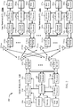
- FIG. 2 illustrates a block diagram of access point 110 and two user terminals 120m and 120x in MIMO system 100.
- the access point 110 is equipped with N t antennas 224a through 224t.
- User terminal 120m is equipped with N ut , m antennas 252ma through 252mu
- user terminal 120x is equipped with N ut , x antennas 252xa through 252xu.
- the access point 110 is a transmitting entity for the downlink and a receiving entity for the uplink.
- Each user terminal 120 is a transmitting entity for the uplink and a receiving entity for the downlink.
- a “transmitting entity” is an independently operated apparatus or device capable of transmitting data via a wireless channel
- a “receiving entity” is an independently operated apparatus or device capable of receiving data via a wireless channel.
- the subscript " dn " denotes the downlink
- the subscript " up " denotes the uplink
- N up user terminals are selected for simultaneous transmission on the uplink
- N dn user terminals are selected for simultaneous transmission on the downlink
- N up may or may not be equal to N dn
- N up and N dn may be static values or can change for each scheduling interval.
- the beam-steering or some other spatial processing technique may be used at the access point and user terminal.
- a transmit (TX) data processor 288 receives traffic data from a data source 286 and control data from a controller 280.
- TX data processor 288 processes (e.g., encodes, interleaves, and modulates) the traffic data for the user terminal based on the coding and modulation schemes associated with the rate selected for the user terminal and provides a data symbol stream.
- a TX spatial processor 290 performs spatial processing on the data symbol stream and provides N ut , m transmit symbol streams for the N ut , m antennas.
- Each transmitter unit (TMTR) 254 receives and processes (e.g., converts to analog, amplifies, filters, and frequency upconverts) a respective transmit symbol stream to generate an uplink signal.
- N ut , m transmitter units 254 provide N ut , m uplink signals for transmission from N ut , m antennas 252 to the access point.
- N up user terminals may be scheduled for simultaneous transmission on the uplink.
- Each of these user terminals performs spatial processing on its data symbol stream and transmits its set of transmit symbol streams on the uplink to the access point.
- N ap antennas 224a through 224ap receive the uplink signals from all N up user terminals transmitting on the uplink.
- Each antenna 224 provides a received signal to a respective receiver unit (RCVR) 222.
- Each receiver unit 222 performs processing complementary to that performed by transmitter unit 254 and provides a received symbol stream.
- An RX spatial processor 240 performs receiver spatial processing on the N ap received symbol streams from N ap receiver units 222 and provides N up recovered uplink data symbol streams.
- the receiver spatial processing is performed in accordance with the channel correlation matrix inversion (CCMI), minimum mean square error (MMSE), soft interference cancellation (SIC), or some other technique.
- Each recovered uplink data symbol stream is an estimate of a data symbol stream transmitted by a respective user terminal.
- An RX data processor 242 processes (e.g., demodulates, deinterleaves, and decodes) each recovered uplink data symbol stream in accordance with the rate used for that stream to obtain decoded data.
- the decoded data for each user terminal may be provided to a data sink 244 for storage and/or a controller 230 for further processing.
- a TX data processor 210 receives traffic data from a data source 208 for N dn user terminals scheduled for downlink transmission, control data from a controller 230, and possibly other data from a scheduler 234. The various types of data may be sent on different transport channels. TX data processor 210 processes (e.g., encodes, interleaves, and modulates) the traffic data for each user terminal based on the rate selected for that user terminal. TX data processor 210 provides N dn downlink data symbol streams for the N dn user terminals.
- a TX spatial processor 220 performs spatial processing (such as a precoding or beamforming, as described in the present disclosure) on the N dn downlink data symbol streams, and provides N ap transmit symbol streams for the N ap antennas.
- Each transmitter unit 222 receives and processes a respective transmit symbol stream to generate a downlink signal.
- N ap transmitter units 222 providing N ap downlink signals for transmission from N ap antennas 224 to the user terminals.
- N ut , m antennas 252 receive the N ap downlink signals from access point 110.
- Each receiver unit 254 processes a received signal from an associated antenna 252 and provides a received symbol stream.
- An RX spatial processor 260 performs receiver spatial processing on N ut , m received symbol streams from N ut , m receiver units 254 and provides a recovered downlink data symbol stream for the user terminal. The receiver spatial processing is performed in accordance with the CCMI, MMSE or some other technique.
- An RX data processor 270 processes (e.g., demodulates, deinterleaves and decodes) the recovered downlink data symbol stream to obtain decoded data for the user terminal.
- a channel estimator 278 estimates the downlink channel response and provides downlink channel estimates, which may include channel gain estimates, SNR estimates, noise variance and so on.
- a channel estimator 228 estimates the uplink channel response and provides uplink channel estimates.
- Controller 280 for each user terminal typically derives the spatial filter matrix for the user terminal based on the downlink channel response matrix H dn,m for that user terminal.
- Controller 230 derives the spatial filter matrix for the access point based on the effective uplink channel response matrix H up,eff .
- Controller 280 for each user terminal may send feedback information (e.g., the downlink and/or uplink eigenvectors, eigenvalues, SNR estimates, and so on) to the access point.
- Controllers 230 and 280 also control the operation of various processing units at access point 110 and user terminal 120, respectively.
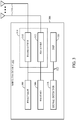
- FIG. 3 illustrates various components that may be utilized in a wireless device 302 that may be employed within the MIMO system 100.
- the wireless device 302 is an example of a device that may be configured to implement the various methods described herein.
- the wireless device 302 may be an access point 110 or a user terminal 120.
- the wireless device 302 may include a processor 304 which controls operation of the wireless device 302.
- the processor 304 may also be referred to as a central processing unit (CPU).
- Memory 306 which may include both read-only memory (ROM) and random access memory (RAM), provides instructions and data to the processor 304.
- a portion of the memory 306 may also include non-volatile random access memory (NVRAM).
- the processor 304 typically performs logical and arithmetic operations based on program instructions stored within the memory 306.
- the instructions in the memory 306 may be executable to implement the methods described herein.
- the wireless device 302 may also include a housing 308 that may include a transmitter 310 and a receiver 312 to allow transmission and reception of data between the wireless device 302 and a remote location.
- the transmitter 310 and receiver 312 may be combined into a transceiver 314.
- a single or a plurality of transmit antennas 316 may be attached to the housing 308 and electrically coupled to the transceiver 314.
- the wireless device 302 may also include (not shown) multiple transmitters, multiple receivers, and multiple transceivers.
- the wireless device 302 may also include a signal detector 318 that may be used in an effort to detect and quantify the level of signals received by the transceiver 314.
- the signal detector 318 may detect such signals as total energy, energy per subcarrier per symbol, power spectral density and other signals.
- the wireless device 302 may also include a digital signal processor (DSP) 320 for use in processing signals.
- DSP digital signal processor
- the various components of the wireless device 302 may be coupled together by a bus system 322, which may include a power bus, a control signal bus, and a status signal bus in addition to a data bus.
- a bus system 322 may include a power bus, a control signal bus, and a status signal bus in addition to a data bus.
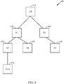
- a relay system utilizing low power devices as relays, it may be desirable to allow relays to enter a low power mode (e.g., sleep with one or more components powered down) whenever possible to reduce power consumption. Further, to keep costs down, it may be desirable to use relays with only limited memory. Thus, a relay may be able to buffer only a small amount of data, and may need to forward the data before being able to receive more.
- a low power mode e.g., sleep with one or more components powered down
- a relay may be able to buffer only a small amount of data, and may need to forward the data before being able to receive more.
- Techniques presented herein may be considered part of a power savings protocol that achieves the above two goals, allowing devices to conserve power and operate with limited amount memory.
- various mechanisms already defined in certain standards e.g., 802.11 ah
- 802.11 ah for use in direct communications between an AP and stations, may be modified and extended for use in relay systems.
- relay devices 430 between access points (APs) 410 and stations 420.
- APs access points
- stations 420 there may be motivations to utilize relay devices 430 between access points (APs) 410 and stations 420.
- the use of relays may be desirable because, even with a potential increased downlink (DL) range with 900MHz (or other "sub-1GHz) carrier, it may not be sufficient in applications with remote sensors or scenarios with obstructions in AP to STA path.
- DL downlink
- 900MHz or other "sub-1GHz
- a relay-node may be formed by any suitable entity, such as a non-AP-STA (e.g., any station that lacks the ability to act-or is not currently acting-as an AP) that connects to a parent node or an AP-STA that allows association by child nodes.
- Node-to-node security may be ensured, for example, by the configuration of PSK between each pair of nodes.
- Relay nodes may support 4-address format with backward learning bridge. In some cases, automatic configuration and reconfiguration may be achieved, for example, with a relay node able to attach to a better "parent node.”
- a relay node may, thus, monitor the health of the link to a parent node.
- a relay node may also be configured to enter a low power state (e.g., a sleep mode with radio components powered down) in order to conserve battery power.
- a relay node may be configured with scheduled wakeup periods, during which the relay node may transmit and receive data. To conserve power, however, rather than exit the low power state each wakeup period, a relay may decide to exit the low power state only when one or more conditions are met (e.g., when there has been an indication there is data for the relay node to transmit or receive).
- an AP and STA may perform similar (e.g., symmetric or complementary) operations. Therefore, for many of the techniques described herein, an AP or STA may perform similar operations. To that end, the following description will sometimes refer to an "AP/STA" to reflect that an operation may be performed by either. Although, it should be understood that even if only "AP” or “STA” is used, it does not mean a corresponding operation or mechanism is limited to that type of device.
- a traffic indication map may be provided to indicate which stations have traffic (and therefore should awake to receive that traffic).
- a TIM information element is described in IEEE 802.11 standards, using a bitmap to indicate to any sleeping listening stations if an AP has any buffered frames for it. This TIM IE with the corresponding bitmap is typically sent in on an AP's beacons, with each bit in the bitmap corresponding to the Association Id (AID) of a station. In some cases, an AP may transmit a smaller TIM bitmap, for example, if it expects that only a few number of stations will be asleep.
- bitmap control and length fields of the TIM information element are used to convey a range of AID values corresponding to the partial virtual bitmap.
- a hierarchical approach may be used. For example, as illustrated in the diagram 500 of FIG. 5 the total AID space may be divided into small blocks in a hierarchical manner and only blocks with non-zero values may be transmitted. This approach allows a TIM for a relatively large AID space to be broken into small groups of STAs, which may be easier to maintain. As illustrated, a three level hierarchy may include Pages, blocks within a page, and sub-blocks within a block (e.g., with each sub-block corresponding to 8 individual stations).
- FIG. 6A illustrate an example 600A structure of a partial virtual bitmap for such a hierarchical structure, in accordance with certain aspects of the present disclosure.
- the structure 600A may have variable length encoded block subfields.
- each encoded block subfield 600B may have a block control subfield, block offset subfield, and an encoded block information subfield.
- the block control subfield 600C may indicate what type of encoding mode is used in the encoded block field, with example encoding types shown in table 600D of FIG. 6D .
- a single AID encoding mode may be used.
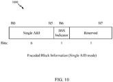
- FIG. 7 illustrates an example structure 700 for encoded block information subfield where the single AID encoding mode is used.
- the encoded block information subfield may include a single AID subfield containing 6 bits (e.g., the 6 least significant bits) of an AID indicated in the block and remaining bits may be reserved.
- the value of the single AID subfield along with other information included in the partial virtual bitmap indicates that there is unicast traffic buffered for a particular station which is identified by its AID.
- the AID of the station may be obtained by concatenating the Single AID subfield, the Block Offset field, and the Page Index field, in sequence from the least significant bit to the most significant bit.
- encoding the partial virtual bitmap that is included in the TIM element may help reduce overhead (relative to a "baseline mechanism" of transmitting a bitmap with bits for an entire AID space).
- the baseline mechanism may not readily allow for the indication of traffic buffered at one or more BSSs while operating in a Multiple BSSID mode.
- aspects of the present disclosure may provide signaling mechanisms to enable a Multiple BSSID mode and other group-cast traffic delivery mechanisms in systems (e.g., 802.11ah systems) by using an encoded Partial Virtual Bitmap field that may be defined for stations capable of supporting such a mode (e.g., sub-1GHz "S1G" STAs).
- group-cast generally refers to traffic addressed to more than one recipient, such as multicast and broadcast traffic.
- Techniques presented herein may avoid having to re-use an AID space from which AIDs are assigned to non-AP STAs in order to identify multiple BSSs. As described in greater detail below, techniques presented herein may identify these BSSs by using BSS AIDs that are included in Encoded Blocks that may be called Encoded BSS Blocks.
- FIG. 8 illustrates example operations 800 for wireless communications by an apparatus, in accordance with aspects of the present disclosure.
- the operations 800 may be performed by an apparatus, such as a station, acting as an access point.
- Operations 800 may begin at 802, by generating a frame with an information element (IE) having a partial virtual bitmap field that indicates one or more basic service sets (BSSs) that have buffered group-cast traffic, wherein the partial virtual bitmap field comprises at least one encoded subfield that identifies at least one individual BSS having buffered group-cast traffic using an identifier of the individual BSS (e.g., a BSS AID).
- the apparatus outputs the frame containing the IE for transmission.
- FIG. 9 is a block diagram of operations 900 for wireless communications by an apparatus, in accordance with aspects of the present disclosure.
- the operations 900 may be performed by an apparatus, such as a TIM station.
- Operations 900 may begin at 902, by receiving a frame containing an information element (IE), wherein the IE comprises a partial virtual bitmap field that indicates zero or more basic service sets (BSSs) that have buffered group-cast traffic and at least one encoded subfield that identifies at least one individual BSS having buffered group-cast traffic using an identifier of the individual BSS.
- BSSs basic service sets
- At 904 determine the presence of buffered group-cast traffic for the apparatus based on the partial virtual bitmap and to decide whether or not to change at least one power state to receive the buffered group-cast traffic, based on the determination.
- the encoded subfield may be an encoded block field and may comprise a Single AID subfield and the TIM IE further comprises a page index field and block offset field that are combinable with the AID subfield to generate the AID of the individual BSS (BSS AID) as described above.
- the encoded block field comprises an indication (e.g., via the BSS Indicator Bit shown in FIG. 10 ) of whether the identifier derived from the Single AID subfield indicates buffered group-cast traffic for the individual BSS (i.e., a BSS AID) or the whether it indicates unicast traffic for an individual station whose AID may be constructed using the Single AID subfield.
- generation of the AID of the individual BSS uses only a subset of one or more bits of the page index field. In such cases, generation of the AID of the individual BSS uses default values, rather than the values of the certain unused bits of the page index field that is included in the TIM element that carries the partial virtual bitmap field.
- the techniques may be used in systems supporting Multiple BSSID capability, with details of operation determined on a category of stations in the system (e.g., with a first category including non-SlG STAs and a second category including S1G STAs).
- the partial virtual bitmap field may be transmitted in a BSSID Beacon, S1G Beacon or DMG Beacon frame, may indicate the presence or absence of traffic to be delivered to all stations associated to a transmitted or non-transmitted BSSID.
- the first 2 n bits of the bitmap in the Partial Virtual Bitmap field may be reserved for the indication of group addressed frame for the transmitted and all non-transmitted BSSIDs.
- the first zero or more Encoded Blocks in the Partial Virtual Bitmap field may be reserved for the indication of group addressed frame for the transmitted and all non-transmitted BSSIDs.
- the AID space may be shared by all BSSs and the lowest AID value assigned to an associated STA may be 2 n .
- the lowest AID assigned to an associated STA may be 1.
- the Encoded Blocks that contain BSS AIDs may be the first blocks, preceding the Partial Virtual Bitmap field. Note that in the cases of the first category any encoding method can be applied to the partial virtual bitmap. In these cases the same principle of ignoring the page index value for the purpose of obtaining the BSS AID is still valid.
- the Partial Virtual Bitmap field consists of octets numbered N1 to N2 of the traffic indication virtual bitmap, where N1 is the largest even number such that bits numbered 1 to (N1 x 8) - 1 in the traffic indication virtual bitmap may be all 0 and N2 may be the smallest number such that bits numbered (N2 + 1) x 8 to 2007 in the virtual bitmap are all 0.
- the Bitmap Offset subfield value may contain the number N1/2, and the Length field is set to (N2 - N1) + 4.
- the bits 1 to k of the bitmap may be used to indicate that one or more group addressed frames are buffered for each AP corresponding to a nontransmitted BSSID.
- the AIDs from 1 to k are not allocated to a non-SlG STA.
- the AIDs from (k + 1) to (2 n - 1) may be reserved and set to 0.
- the remaining AIDs may be shared by the non-SlG BSSs corresponding to the transmitted BSSID and all nontransmitted BSSIDs.
- these bits, 1 to k may be included in BSS Encoded Blocks and are identified as BSS AIDs.
- the BSS AIDs may not form part of the AID space from which AIDs are assigned to non-AP STAs.
- the AID space may be shared by the S1G BSSs corresponding to the transmitted BSSID and all nontransmitted BSSIDs.
- DTIM Count field is 0 for a BSS that has a nontransmitted BSSID, and one or more group addressed frames are buffered at the AP for this BSS, and the corresponding bits from bit 1 to bit k may be set to 1.
- Each bit starting from bit 2 n in the non-SlG traffic-indication virtual bitmap and starting from bit 1 in the S1G traffic-indication virtual bitmap may correspond to individually addressed traffic buffered for a specific STA within any BSS corresponding to a transmitted or nontransmitted BSSID at the time the Beacon frame is transmitted.
- the correspondence may be based on the AID of the STA.
- the AP may encode the Partial Virtual Bitmap and the Bitmap Control field of the TIM element using one of the three following methods, with the particular operations depending on the category of stations in the system.
- an AP may use one method (referred to as Method B described below) when it determines that the bit for each associated non-AP STA in the traffic indication virtual bitmap, when correctly set, can be reconstructed by each non-AP STA from the received TIM element. Otherwise, the AP may use a second method (referred to Method A described below), while an AP in a system with a second category of stations (e.g., S1G) may use a third method (referred to as Method C described below).
- the Bitmap Offset subfield value may contains the number 0, and the Length field is N2 + 4.
- the Partial Virtual Bitmap field may consist of a concatenation of octets numbered 0 to N0 - 1 and octets numbered N1 to N2 of the traffic indication virtual bitmap, where N0 is the smallest positive integer such that N0 ⁇ 8 - 2n ⁇ 8. If N0 is an odd number, then N1 is the largest odd number such that N0 ⁇ N1 and each of the bits N0 ⁇ 8 to (N1 ⁇ 8 - 1) is equal to 0. When N0 is an even number, N1 is the largest even number such that N0 ⁇ N1 and each of the bits N0 ⁇ 8 to (N1 ⁇ 8 - 1) is equal to 0.
- N1 N0.
- the Bitmap Offset subfield contains the value of (N1 - N0)/2, and the Length field is N0 + N2 - N1 + 4.
- the Partial Virtual Bitmap field may consist of a concatenation of Encoded Block subfields that contain BSS AIDs and Encoded Block subfields that contain AIDs.
- the Partial Virtual Bitmap field may be encoded as a single octet equal to 0, the Bitmap Offset subfield is 0, and the Length field is 4.
- the non-SlG Partial Virtual Bitmap field consists of the octets number 0 to N0 - 1 where N0 is the smallest positive integer such that (N0 ⁇ 8 - 2n ⁇ 8), while the S1G Partial Virtual Bitmap field contains the one or more Encoded Blocks that contain BSS AIDs.
- the Bitmap Offset subfield value may contain the number 0, and the Length field may be N0+3.
- the Partial Virtual Bitmap field may be constructed with one or more Encoded Block subfields if at least one bit in the traffic indication virtual bitmap that is encoded with that particular encoding method is equal to 1.
- the Encoded Block subfield may consist of the Block Control subfield, the Block Offset subfield, and the Encoded Block Information subfield.
- the Partial Virtual Bitmap field contains zero or more BSS Encoded Block subfields.
- the Encoding Mode subfield may indicates one of the four encoding modes: the Block Bitmap mode, the Single AID mode, the OLB (Offset, Length, Bitmap) mode, and the ADE (AID Differential Encode) mode.
- An Encoded Block is encoded with Single AID mode and includes a BSS AID (i.e., the BSS Indicator subfield of its Encoded Block Information subfield is equal to 1).
- An Encoded Block with Single AID mode that is not an Encoded BSS Block has the BSS Indicator subfield of its Subblock equal to 0. Other methods can be used as well, as indicated above.
- the Encoded Block Information subfield 1000 may consist of the Single AID subfield.
- the Single AID subfield may be 6 bits in length and contains the 6 LSBs of the single AID in the Block.
- the BSS Indicator may be set to 1 if the Single AID identifies a BSS AID. Otherwise, it may be set to 0.
- the rest of the bits of the Encoded Block Information subfield may be reserved.
- the value in the Single AID subfield may indicate traffic buffered for the STA whose AID is N, where N may be constructed by concatenating the Single AID subfield(N[0:5]), the Block Offset field (N[6:10]), and the Page Index field (N[11:12]) in sequence from LSB to MSB.
- the value in the Single AID subfield indicates that one or more group addressed are buffered at the AP for the BSS which BSS AID is N, where N may be constructed as described above but with the value of the Page Index field (N[11:12]) equal to 0 (i.e., the BSS AID does not depend on the value of the Page Index field in the Bitmap Control field).
- the value in the Single AID subfield may indicate traffic buffered for the STA whose AID is N, where N is constructed by concatenating the Single AID subfield(N[0:5]), the Block Offset field (N[6:10]), and the Page Index field (N[11:12]) in sequence from LSB to MSB.
- the value in the Single AID subfield may indicate that one or more types of group addressed traffic is buffered at the AP for the BSS which BSS AID is N, where the value of the Page Index field (N[11:12]) may be assumed to be a default value (e.g., a default value of 0 may be assumed for either or both of these bits regardless of the Page Index field value in the Bitmap Control field of the TIM element).
- the various operations of methods described above may be performed by any suitable means capable of performing the corresponding functions.
- the means may include various hardware and/or software component(s) and/or module(s), including, but not limited to a circuit, an application specific integrated circuit (ASIC), or processor.
- ASIC application specific integrated circuit
- operations 800 and 900 illustrated in FIGs. 8 and 9 correspond to means 800A and 900A illustrated in FIGs. 8A and 9A , respectively.
- means for transmitting may comprise a transmitter (e.g., the transmitter unit 222) and/or an antenna(s) 224 of the access point 110 illustrated in FIG. 2 or the transmitter 310 and/or antenna(s) 316 depicted in FIG. 3 .
- Means for receiving may comprise a receiver (e.g., the receiver unit 222) and/or an antenna(s) 224 of the access point 110 illustrated in FIG. 2 or the receiver 312 and/or antenna(s) 316 depicted in FIG. 3 .
- Means for processing, means for determining, means for detecting, means for scanning, means for selecting, means for generating, or means for terminating operation may comprise a processing system, which may include one or more processors, such as the RX data processor 242, the TX data processor 210, and/or the controller 230 of the access point 110 illustrated in FIG. 2 or the processor 304 and/or the DSP 320 portrayed in FIG. 3 .
- processors such as the RX data processor 242, the TX data processor 210, and/or the controller 230 of the access point 110 illustrated in FIG. 2 or the processor 304 and/or the DSP 320 portrayed in FIG. 3 .
- such means may be implemented by processing systems configured to perform the corresponding functions by implementing various algorithms (e.g., in hardware or by executing software instructions) described above for performing fast association.
- means for identifying wakeup periods may be implemented by a processing system performing an algorithm that identifies wakeup periods based on a configuration (e.g., via an IE)
- means for determining whether to enable radio functions during wakeup periods may be implemented by a (same or different) processing system performing an algorithm that takes, as input, the wakeup periods and whether the presence of data has been indicated
- means for enabling radio functions may be implemented a (same or different) processing system performing an algorithm that takes, as input, the decision from means for determining and generates signals to enable/disable the radio functions accordingly.
- determining encompasses a wide variety of actions. For example, “determining” may include calculating, computing, processing, deriving, investigating, looking up (e.g., looking up in a table, a database or another data structure), ascertaining and the like. Also, “determining” may include receiving (e.g., receiving information), accessing (e.g., accessing data in a memory) and the like. Also, “determining” may include resolving, selecting, choosing, establishing and the like.
- the term receiver may refer to an RF receiver (e.g., of an RF front end) or an interface (e.g., of a processor) for receiving structures processed by an RF front end (e.g., via a bus).
- the term transmitter may refer to an RF transmitter of an RF front end or an interface (e.g., of a processor) for outputting structures to an RF front end for transmission (e.g., via a bus).
- a phrase referring to "at least one of' a list of items refers to any combination of those items, including single members.
- "at least one of: a , b, or c" is intended to cover: a , b, c, a-b , a-c , b-c , and a-b-c , as well as any combination with multiples of the same element (e.g., a-a , a-a-a , a-a-b , a-a-c , a-b-b , a- c-c , b-b , b-b-b , b-b-c , c-c , and c-c-c or any other ordering of a, b, and c ).
- DSP digital signal processor
- ASIC application specific integrated circuit
- FPGA field programmable gate array
- PLD programmable logic device
- a general-purpose processor may be a microprocessor, but in the alternative, the processor may be any commercially available processor, controller, microcontroller, or state machine.
- a processor may also be implemented as a combination of computing devices, e.g., a combination of a DSP and a microprocessor, a plurality of microprocessors, one or more microprocessors in conjunction with a DSP core, or any other such configuration.
- a software module may reside in any form of storage medium that is known in the art. Some examples of storage media that may be used include random access memory (RAM), read only memory (ROM), flash memory, EPROM memory, EEPROM memory, registers, a hard disk, a removable disk, a CD-ROM and so forth.
- RAM random access memory
- ROM read only memory
- flash memory EPROM memory
- EEPROM memory EEPROM memory
- registers a hard disk, a removable disk, a CD-ROM and so forth.
- a software module may comprise a single instruction, or many instructions, and may be distributed over several different code segments, among different programs, and across multiple storage media.
- a storage medium may be coupled to a processor such that the processor can read information from, and write information to, the storage medium. In the alternative, the storage medium may be integral to the processor.
- the methods disclosed herein comprise one or more steps or actions for achieving the described method.
- the method steps and/or actions may be interchanged with one another without departing from the scope of the claims.
- the order and/or use of specific steps and/or actions may be modified without departing from the scope of the claims.
- an example hardware configuration may comprise a processing system in a wireless node.
- the processing system may be implemented with a bus architecture.
- the bus may include any number of interconnecting buses and bridges depending on the specific application of the processing system and the overall design constraints.
- the bus may link together various circuits including a processor, machine-readable media, and a bus interface.
- the bus interface may be used to connect a network adapter, among other things, to the processing system via the bus.
- the network adapter may be used to implement the signal processing functions of the PHY layer.
- a user terminal 120 see FIG.
- a user interface e.g., keypad, display, mouse, joystick, etc.
- the bus may also link various other circuits such as timing sources, peripherals, voltage regulators, power management circuits, and the like, which are well known in the art, and therefore, will not be described any further.
- the processor may be responsible for managing the bus and general processing, including the execution of software stored on the machine-readable media.
- the processor may be implemented with one or more general-purpose and/or special-purpose processors. Examples include microprocessors, microcontrollers, DSP processors, and other circuitry that can execute software.
- Software shall be construed broadly to mean instructions, data, or any combination thereof, whether referred to as software, firmware, middleware, microcode, hardware description language, or otherwise.
- Machine-readable media may include, by way of example, RAM (Random Access Memory), flash memory, ROM (Read Only Memory), PROM (Programmable Read-Only Memory), EPROM (Erasable Programmable Read-Only Memory), EEPROM (Electrically Erasable Programmable Read-Only Memory), registers, magnetic disks, optical disks, hard drives, or any other suitable storage medium, or any combination thereof.
- RAM Random Access Memory
- ROM Read Only Memory
- PROM Programmable Read-Only Memory
- EPROM Erasable Programmable Read-Only Memory
- EEPROM Electrically Erasable Programmable Read-Only Memory
- registers magnetic disks, optical disks, hard drives, or any other suitable storage medium, or any combination thereof.
- the machine-readable media may be embodied in a computer-program product.
- the computer-program product may comprise packaging materials.
- the machine-readable media may be part of the processing system separate from the processor.
- the machine-readable media, or any portion thereof may be external to the processing system.
- the machine-readable media may include a transmission line, a carrier wave modulated by data, and/or a computer product separate from the wireless node, all which may be accessed by the processor through the bus interface.
- the machine-readable media, or any portion thereof may be integrated into the processor, such as the case may be with cache and/or general register files.
- the processing system may be configured as a general-purpose processing system with one or more microprocessors providing the processor functionality and external memory providing at least a portion of the machine-readable media, all linked together with other supporting circuitry through an external bus architecture.
- the processing system may be implemented with an ASIC (Application Specific Integrated Circuit) with the processor, the bus interface, the user interface in the case of an access terminal), supporting circuitry, and at least a portion of the machine-readable media integrated into a single chip, or with one or more FPGAs (Field Programmable Gate Arrays), PLDs (Programmable Logic Devices), controllers, state machines, gated logic, discrete hardware components, or any other suitable circuitry, or any combination of circuits that can perform the various functionality described throughout this disclosure.
- FPGAs Field Programmable Gate Arrays
- PLDs Programmable Logic Devices
- controllers state machines, gated logic, discrete hardware components, or any other suitable circuitry, or any combination of circuits that can perform the various functionality described throughout this disclosure.
- the machine-readable media may comprise a number of software modules.
- the software modules include instructions that, when executed by the processor, cause the processing system to perform various functions.
- the software modules may include a transmission module and a receiving module.
- Each software module may reside in a single storage device or be distributed across multiple storage devices.
- a software module may be loaded into RAM from a hard drive when a triggering event occurs.
- the processor may load some of the instructions into cache to increase access speed.
- One or more cache lines may then be loaded into a general register file for execution by the processor.
- Computer-readable media include both computer storage media and communication media including any medium that facilitates transfer of a computer program from one place to another.
- a storage medium may be any available medium that can be accessed by a computer.
- such computer-readable media can comprise RAM, ROM, EEPROM, CD-ROM or other optical disk storage, magnetic disk storage or other magnetic storage devices, or any other medium that can be used to carry or store desired program code in the form of instructions or data structures and that can be accessed by a computer.
- any connection is properly termed a computer-readable medium.
- Disk and disc include compact disc (CD), laser disc, optical disc, digital versatile disc (DVD), floppy disk, and Blu-ray® disc where disks usually reproduce data magnetically, while discs reproduce data optically with lasers.
- computer-readable media may comprise non-transitory computer-readable media (e.g., tangible media).
- computer-readable media may comprise transitory computer- readable media (e.g., a signal). Combinations of the above should also be included within the scope of computer-readable media.
- certain aspects may comprise a computer program product for performing the operations presented herein.
- a computer program product may comprise a computer-readable medium having instructions stored (and/or encoded) thereon, the instructions being executable by one or more processors to perform the operations described herein.
- the computer program product may include packaging material.
- modules and/or other appropriate means for performing the methods and techniques described herein can be downloaded and/or otherwise obtained by a user terminal and/or base station as applicable.
- a user terminal and/or base station can be coupled to a server to facilitate the transfer of means for performing the methods described herein.
- various methods described herein can be provided via storage means (e.g., RAM, ROM, a physical storage medium such as a compact disc (CD) or floppy disk, etc.), such that a user terminal and/or base station can obtain the various methods upon coupling or providing the storage means to the device.
- storage means e.g., RAM, ROM, a physical storage medium such as a compact disc (CD) or floppy disk, etc.
- CD compact disc
- floppy disk etc.
- any other suitable technique for providing the methods and techniques described herein to a device can be utilized.
Description
- Certain aspects of the present disclosure generally relate to wireless communications and, more particularly, to multiple BSSID with TIM encoding.
- Wireless communication networks are widely deployed to provide various communication services such as voice, video, packet data, messaging, broadcast, etc. These wireless networks may be multiple-access networks capable of supporting multiple users by sharing the available network resources. Examples of such multiple-access networks include Code Division Multiple Access (CDMA) networks, Time Division Multiple Access (TDMA) networks, Frequency Division Multiple Access (FDMA) networks, Orthogonal FDMA (OFDMA) networks, and Single-Carrier FDMA (SC-FDMA) networks.
- In order to address the desire for greater coverage and increased communication range, various schemes are being developed. One such scheme is the sub-1-GHz frequency range (e.g., operating in the 902 - 928 MHz range in the United States) being developed by the Institute of Electrical and Electronics Engineers (IEEE) 802.11ah task force. This development is driven by the desire to utilize a frequency range that has greater wireless range than other IEEE 802.11 groups and has lower obstruction losses.
-
US 2009/016306 A1 discloses a method for communicating data comprising generating a traffic indication virtual bitmap based on the presence of stored data that is pending transmission via a wireless communication medium, and generating a partial virtual bitmap based on said generated traffic indication virtual bitmap, wherein said partial virtual bitmap comprises a first segment from said generated traffic indication virtual bitmap and a second segment from said generated traffic indication virtual bitmap. - The invention is defined in the independent claims. Certain aspects of the present disclosure provide an apparatus for wireless communications. The apparatus typically includes a processing system configured to generate a frame with an information element (IE) having a partial virtual bitmap field that indicates one or more basic service sets (BSSs) that have buffered group-cast traffic, wherein the partial virtual bitmap field comprises at least one encoded subfield that identifies at least one individual BSS having buffered group-cast traffic using one or more bits of an association identification or assigned identification (AID) of the individual BSS and an interface for outputting a frame containing the IE for transmission.
- Certain aspects of the present disclosure provide an apparatus for wireless communications. The apparatus typically includes an interface for receiving a frame containing an information element (IE) and a processing system configured to determine the presence of buffered group-cast traffic for the apparatus based on a partial virtual bitmap field in the IE that indicates one or more basic service sets (BSSs) that have buffered group-cast traffic, wherein the bitmap field comprises at least one encoded subfield that identifies at least one individual BSS having buffered group-cast traffic using one or more bits of an association identification or assigned identification (AID) of the individual BSS.
- Certain aspects of the present disclosure provide a method for wireless communications by an apparatus. The method typically includes generating, at an apparatus, a frame with an information element (IE) having a partial virtual bitmap field that indicates zero or more basic service sets (BSSs) that have buffered group-cast traffic, wherein the partial virtual bitmap field comprises at least one encoded subfield that identifies at least one individual BSS having buffered group-cast traffic using one or more bits of an identifier of the individual BSS, and outputting the frame containing the IE for transmission.
- Certain aspects of the present disclosure provide a method for wireless communications by an apparatus. The method typically includes receiving, at an apparatus, a frame containing an information element (IE), wherein the IE comprises a partial virtual bitmap field that indicates zero or more basic service sets (BSSs) that have buffered group-cast traffic and at least one encoded subfield that identifies at least one individual BSS having buffered group-cast traffic using one or more bits of an identifier of the individual BSS, and determining the presence of buffered group-cast traffic for the apparatus based on the partial virtual bitmap and to decide whether or not to change at least one power state to receive the buffered group-cast traffic, based on the determination.
- Certain aspects of the present disclosure provide an apparatus for wireless communications. The apparatus typically includes means for generating a frame with an information element (IE) having a partial virtual bitmap field that indicates zero or more basic service sets (BSSs) that have buffered group-cast traffic, wherein the partial virtual bitmap field comprises at least one encoded subfield that identifies at least one individual BSS having buffered group-cast traffic using one or more bits of an identifier of the individual BSS, and means for outputting the frame containing the IE for transmission.
- Certain aspects of the present disclosure provide an apparatus for wireless communications. The apparatus typically includes means for receiving a frame containing an information element (IE) wherein the IE comprises a partial virtual bitmap field that indicates zero or more basic service sets (BSSs) that have buffered group-cast traffic and at least one encoded subfield that identifies at least one individual BSS having buffered group-cast traffic using one or more bits of an identifier of the individual BSS and means for determining the presence of buffered group-cast traffic for the apparatus based on the partial virtual bitmap and to decide whether or not to change at least one power state to receive the buffered group-cast traffic, based on the determination.
- Certain aspects of the present disclosure provide a computer program product for wireless communications. The computer program product typically comprises a computer-readable medium having instructions for generating a frame with an information element (IE) having a partial virtual bitmap field that indicates zero or more basic service sets (BSSs) that have buffered group-cast traffic, wherein the partial virtual bitmap field comprises at least one encoded subfield that identifies at least one individual BSS having buffered group-cast traffic using one or more bits of an identifier of the individual BSS, and outputting the frame containing the IE for transmission.
- Certain aspects of the present disclosure provide a computer program product for wireless communications. The computer program product typically comprises a computer-readable medium having instructions for receiving, at an apparatus, a frame containing an information element (IE), wherein the IE comprises a partial virtual bitmap field that indicates zero or more basic service sets (BSSs) that have buffered group-cast traffic and at least one encoded subfield that identifies at least one individual BSS having buffered group-cast traffic using one or more bits of an identifier of the individual BSS and determining the presence of buffered group-cast traffic for the apparatus based on the partial virtual bitmap and to decide whether or not to change at least one power state to receive the buffered group-cast traffic, based on the determination.
- Certain aspects of the present disclosure provide an access point. The access point typically includes at least one antenna, a processing system configured to generate a frame with an information element (IE) having a partial virtual bitmap field that indicates zero or more basic service sets (BSSs) that have buffered group-cast traffic, wherein the partial virtual bitmap field comprises at least one encoded subfield that identifies at least one individual BSS having buffered group-cast traffic using one or more bits of an identifier of the individual BSS, and a transmitter configured to transmit, via the at least one antenna, the frame containing the IE for transmission.
- Certain aspects of the present disclosure provide an access point. The access point typically includes at least one antenna, a a receiver configured to receive, via the at least one antenna, a frame containing an information element (IE), wherein the IE comprises a partial virtual bitmap field that indicates zero or more basic service sets (BSSs) that have buffered group-cast traffic and at least one encoded subfield that identifies at least one individual BSS having buffered group-cast traffic using one or more bits of an identifier of the individual BSS, and a processing system configured to determine the presence of buffered group-cast traffic for the apparatus based on the partial virtual bitmap and to decide whether or not to change at least one power state to receive the buffered group-cast traffic, based on the determination.
- Certain aspects also provide various methods, apparatuses, and computer program products capable of performing operations corresponding to those described above.
- So that the manner in which the above-recited features of the present disclosure can be understood in detail, a more particular description, briefly summarized above, may be had by reference to aspects, some of which are illustrated in the appended drawings. It is to be noted, however, that the appended drawings illustrate only certain typical aspects of this disclosure and are therefore not to be considered limiting of its scope, for the description may admit to other equally effective aspects.
-
FIG. 1 illustrates a diagram of an example wireless communications network, in accordance with certain aspects of the present disclosure. -
FIG. 2 illustrates a block diagram of an example access point and user terminals, in accordance with certain aspects of the present disclosure. -
FIG. 3 illustrates a block diagram of an example wireless device, in accordance with certain aspects of the present disclosure. -
FIG. 4 illustrates an example tree structure of a relay system, in accordance with certain aspects of the present disclosure. -
FIG. 5 illustrates an example hierarchical structure of a traffic indication map (TIM), in accordance with certain aspects of the present disclosure. -
FIGs. 6A-6C illustrates example structures of a partial virtual bitmap for a block encoding mode, in accordance with certain aspects of the present disclosure. -
FIG. 7 illustrates an example structure of a partial virtual bitmap for a single association ID (AID) mode, in accordance with certain aspects of the present disclosure. -
FIG. 8 illustrates a block diagram of example operations for wireless communications, in accordance with certain aspects of the present disclosure. -
FIG. 8A illustrates example means capable of performing the operations shown inFIG. 8 . -
FIG. 9 illustrates a block diagram of example operations for wireless communications, in accordance with certain aspects of the present disclosure. -
FIG. 9A illustrates example means capable of performing the operations shown inFIG. 9 . -
FIG. 10 illustrates an example structure for an encoded block of a partial virtual bitmap, in accordance with aspects of the present disclosure. - Aspects of the present disclosure provide enhancements to mechanisms involving certain selective transmission mechanisms, such as partial virtual bitmaps (PVB) and multiple basic service set IDs (BSSIDs). By providing an indication of multiple BSSID in a partial virtual bitmap (PVB) of a Traffic Indication Map (TIM) Information Element (IE), support for multiple BSS while using an association identification (AID) may be provided.
- Various aspects of the disclosure are described more fully hereinafter with reference to the accompanying drawings. This disclosure may, however, be embodied in many different forms and should not be construed as limited to any specific structure or function presented throughout this disclosure. Rather, these aspects are provided so that this disclosure will be thorough and complete, and will fully convey the scope of the disclosure to those skilled in the art. Based on the teachings herein one skilled in the art should appreciate that the scope of the disclosure is intended to cover any aspect of the disclosure disclosed herein, whether implemented independently of or combined with any other aspect of the disclosure. For example, an apparatus may be implemented or a method may be practiced using any number of the aspects set forth herein. In addition, the scope of the disclosure is intended to cover such an apparatus or method which is practiced using other structure, functionality, or structure and functionality in addition to or other than the various aspects of the disclosure set forth herein. It should be understood that any aspect of the disclosure disclosed herein may be embodied by one or more elements of a claim.
- Although particular aspects are described herein, many variations and permutations of these aspects fall within the scope of the disclosure. Although some benefits and advantages of the preferred aspects are mentioned, the scope of the disclosure is not intended to be limited to particular benefits, uses, or objectives. Rather, aspects of the disclosure are intended to be broadly applicable to different wireless technologies, system configurations, networks, and transmission protocols, some of which are illustrated by way of example in the figures and in the following description of the preferred aspects. The detailed description and drawings are merely illustrative of the disclosure rather than limiting, the scope of the disclosure being defined by the appended claims and equivalents thereof.
- The techniques described herein may be used for various broadband wireless communication systems, including communication systems that are based on an orthogonal multiplexing scheme. Examples of such communication systems include Spatial Division Multiple Access (SDMA), Time Division Multiple Access (TDMA), Orthogonal Frequency Division Multiple Access (OFDMA) systems, Single-Carrier Frequency Division Multiple Access (SC-FDMA) systems, and so forth. An SDMA system may utilize sufficiently different directions to simultaneously transmit data belonging to multiple user terminals. A TDMA system may allow multiple user terminals to share the same frequency channel by dividing the transmission signal into different time slots, each time slot being assigned to different user terminal. An OFDMA system utilizes orthogonal frequency division multiplexing (OFDM), which is a modulation technique that partitions the overall system bandwidth into multiple orthogonal sub-carriers. These sub-carriers may also be called tones, bins, etc. With OFDM, each sub-carrier may be independently modulated with data. An SC-FDMA system may utilize interleaved FDMA (IFDMA) to transmit on sub-carriers that are distributed across the system bandwidth, localized FDMA (LFDMA) to transmit on a block of adjacent sub-carriers, or enhanced FDMA (EFDMA) to transmit on multiple blocks of adjacent sub-carriers. In general, modulation symbols are sent in the frequency domain with OFDM and in the time domain with SC-FDMA.
- The teachings herein may be incorporated into (e.g., implemented within or performed by) a variety of wired or wireless apparatuses (e.g., nodes or devices). In some aspects, a wireless node implemented in accordance with the teachings herein may comprise an access point or an access terminal.
- An access point ("AP") may comprise, be implemented as, or known as a Node B, Radio Network Controller ("RNC"), evolved Node B (eNB), Base Station Controller ("BSC"), Base Transceiver Station ("BTS"), Base Station ("BS"), Transceiver Function ("TF"), Radio Router, Radio Transceiver, Basic Service Set ("BSS"), Extended Service Set ("ESS"), Radio Base Station ("RBS"), or some other terminology.
- An access terminal ("AT") may comprise, be implemented as, or known as a subscriber station, a subscriber unit, a mobile station (MS), a remote station, a remote terminal, a user terminal (UT), a user agent, a user device, user equipment (UE), a user station, or some other terminology. In some implementations, an access terminal may comprise a cellular telephone, a cordless telephone, a Session Initiation Protocol ("SIP") phone, a wireless local loop ("WLL") station, a personal digital assistant ("PDA"), a handheld device having wireless connection capability, a Station ("STA"), or some other suitable processing device connected to a wireless modem. Accordingly, one or more aspects taught herein may be incorporated into a phone (e.g., a cellular phone or smart phone), a computer (e.g., a laptop), a tablet, a portable communication device, a portable computing device (e.g., a personal data assistant), an entertainment device (e.g., a music or video device, or a satellite radio), a global positioning system (GPS) device, or any other suitable device that is configured to communicate via a wireless or wired medium. In some aspects, the node is a wireless node. Such wireless node may provide, for example, connectivity for or to a network (e.g., a wide area network such as the Internet or a cellular network) via a wired or wireless communication link.
-
FIG. 1 illustrates a multiple-access multiple-input multiple-output (MIMO)system 100 with access points and user terminals. For simplicity, only oneaccess point 110 is shown inFIG. 1 . An access point is generally a fixed station that communicates with the user terminals and may also be referred to as a base station or some other terminology. A user terminal may be fixed or mobile and may also be referred to as a mobile station, a wireless device, or some other terminology.Access point 110 may communicate with one or more user terminals 120 at any given moment on the downlink and uplink. The downlink (i.e., forward link) is the communication link from the access point to the user terminals, and the uplink (i.e., reverse link) is the communication link from the user terminals to the access point. A user terminal may also communicate peer-to-peer with another user terminal. Asystem controller 130 couples to and provides coordination and control for the access points. - While portions of the following disclosure will describe user terminals 120 capable of communicating via Spatial Division Multiple Access (SDMA), for certain aspects, the user terminals 120 may also include some user terminals that do not support SDMA. Thus, for such aspects, an
AP 110 may be configured to communicate with both SDMA and non-SDMA user terminals. This approach may conveniently allow older versions of user terminals ("legacy" stations) to remain deployed in an enterprise, extending their useful lifetime, while allowing newer SDMA user terminals to be introduced as deemed appropriate. - The
system 100 employs multiple transmit and multiple receive antennas for data transmission on the downlink and uplink. Theaccess point 110 is equipped with Nap antennas and represents the multiple-input (MI) for downlink transmissions and the multiple-output (MO) for uplink transmissions. A set of K selected user terminals 120 collectively represents the multiple-output for downlink transmissions and the multiple-input for uplink transmissions. For pure SDMA, it is desired to have Nap ≥ K ≥ 1 if the data symbol streams for the K user terminals are not multiplexed in code, frequency or time by some means. K may be greater than Nap if the data symbol streams can be multiplexed using TDMA technique, different code channels with CDMA, disjoint sets of subbands with OFDM, and so on. Each selected user terminal transmits user-specific data to and/or receives user-specific data from the access point. In general, each selected user terminal may be equipped with one or multiple antennas (i.e., Nut ≥1). The K selected user terminals can have the same or different number of antennas. - The SDMA system may be a time division duplex (TDD) system or a frequency division duplex (FDD) system. For a TDD system, the downlink and uplink share the same frequency band. For an FDD system, the downlink and uplink use different frequency bands.
MIMO system 100 may also utilize a single carrier or multiple carriers for transmission. Each user terminal may be equipped with a single antenna (e.g., in order to keep costs down) or multiple antennas (e.g., where the additional cost can be supported). Thesystem 100 may also be a TDMA system if the user terminals 120 share the same frequency channel by dividing transmission/reception into different time slots, each time slot being assigned to different user terminal 120. -
FIG. 2 illustrates a block diagram ofaccess point 110 and two user terminals 120m and 120x inMIMO system 100. Theaccess point 110 is equipped with Nt antennas 224a through 224t. User terminal 120m is equipped with N ut,m antennas 252ma through 252mu, and user terminal 120x is equipped with N ut,x antennas 252xa through 252xu. Theaccess point 110 is a transmitting entity for the downlink and a receiving entity for the uplink. Each user terminal 120 is a transmitting entity for the uplink and a receiving entity for the downlink. As used herein, a "transmitting entity" is an independently operated apparatus or device capable of transmitting data via a wireless channel, and a "receiving entity" is an independently operated apparatus or device capable of receiving data via a wireless channel. In the following description, the subscript "dn" denotes the downlink, the subscript "up" denotes the uplink, Nup user terminals are selected for simultaneous transmission on the uplink, Ndn user terminals are selected for simultaneous transmission on the downlink, Nup may or may not be equal to Ndn , and Nup and Ndn may be static values or can change for each scheduling interval. The beam-steering or some other spatial processing technique may be used at the access point and user terminal. - On the uplink, at each user terminal 120 selected for uplink transmission, a transmit (TX) data processor 288 receives traffic data from a data source 286 and control data from a controller 280. TX data processor 288 processes (e.g., encodes, interleaves, and modulates) the traffic data for the user terminal based on the coding and modulation schemes associated with the rate selected for the user terminal and provides a data symbol stream. A TX spatial processor 290 performs spatial processing on the data symbol stream and provides N ut,m transmit symbol streams for the N ut,m antennas. Each transmitter unit (TMTR) 254 receives and processes (e.g., converts to analog, amplifies, filters, and frequency upconverts) a respective transmit symbol stream to generate an uplink signal. N ut,m transmitter units 254 provide N ut,m uplink signals for transmission from N ut,m antennas 252 to the access point.
- Nup user terminals may be scheduled for simultaneous transmission on the uplink. Each of these user terminals performs spatial processing on its data symbol stream and transmits its set of transmit symbol streams on the uplink to the access point.
- At
access point 110, Nap antennas 224a through 224ap receive the uplink signals from all Nup user terminals transmitting on the uplink. Each antenna 224 provides a received signal to a respective receiver unit (RCVR) 222. Each receiver unit 222 performs processing complementary to that performed by transmitter unit 254 and provides a received symbol stream. An RXspatial processor 240 performs receiver spatial processing on the Nap received symbol streams from Nap receiver units 222 and provides Nup recovered uplink data symbol streams. The receiver spatial processing is performed in accordance with the channel correlation matrix inversion (CCMI), minimum mean square error (MMSE), soft interference cancellation (SIC), or some other technique. Each recovered uplink data symbol stream is an estimate of a data symbol stream transmitted by a respective user terminal. AnRX data processor 242 processes (e.g., demodulates, deinterleaves, and decodes) each recovered uplink data symbol stream in accordance with the rate used for that stream to obtain decoded data. The decoded data for each user terminal may be provided to adata sink 244 for storage and/or acontroller 230 for further processing. - On the downlink, at
access point 110, aTX data processor 210 receives traffic data from adata source 208 for Ndn user terminals scheduled for downlink transmission, control data from acontroller 230, and possibly other data from ascheduler 234. The various types of data may be sent on different transport channels.TX data processor 210 processes (e.g., encodes, interleaves, and modulates) the traffic data for each user terminal based on the rate selected for that user terminal.TX data processor 210 provides Ndn downlink data symbol streams for the Ndn user terminals. A TXspatial processor 220 performs spatial processing (such as a precoding or beamforming, as described in the present disclosure) on the Ndn downlink data symbol streams, and provides Nap transmit symbol streams for the Nap antennas. Each transmitter unit 222 receives and processes a respective transmit symbol stream to generate a downlink signal. Nap transmitter units 222 providing Nap downlink signals for transmission from Nap antennas 224 to the user terminals. - At each user terminal 120, N ut,m antennas 252 receive the Nap downlink signals from
access point 110. Each receiver unit 254 processes a received signal from an associated antenna 252 and provides a received symbol stream. An RX spatial processor 260 performs receiver spatial processing on N ut,m received symbol streams from N ut,m receiver units 254 and provides a recovered downlink data symbol stream for the user terminal. The receiver spatial processing is performed in accordance with the CCMI, MMSE or some other technique. An RX data processor 270 processes (e.g., demodulates, deinterleaves and decodes) the recovered downlink data symbol stream to obtain decoded data for the user terminal. - At each user terminal 120, a channel estimator 278 estimates the downlink channel response and provides downlink channel estimates, which may include channel gain estimates, SNR estimates, noise variance and so on. Similarly, a
channel estimator 228 estimates the uplink channel response and provides uplink channel estimates. Controller 280 for each user terminal typically derives the spatial filter matrix for the user terminal based on the downlink channel response matrix Hdn,m for that user terminal.Controller 230 derives the spatial filter matrix for the access point based on the effective uplink channel response matrix Hup,eff . Controller 280 for each user terminal may send feedback information (e.g., the downlink and/or uplink eigenvectors, eigenvalues, SNR estimates, and so on) to the access point.Controllers 230 and 280 also control the operation of various processing units ataccess point 110 and user terminal 120, respectively. -
FIG. 3 illustrates various components that may be utilized in awireless device 302 that may be employed within theMIMO system 100. Thewireless device 302 is an example of a device that may be configured to implement the various methods described herein. Thewireless device 302 may be anaccess point 110 or a user terminal 120. - The
wireless device 302 may include aprocessor 304 which controls operation of thewireless device 302. Theprocessor 304 may also be referred to as a central processing unit (CPU).Memory 306, which may include both read-only memory (ROM) and random access memory (RAM), provides instructions and data to theprocessor 304. A portion of thememory 306 may also include non-volatile random access memory (NVRAM). Theprocessor 304 typically performs logical and arithmetic operations based on program instructions stored within thememory 306. The instructions in thememory 306 may be executable to implement the methods described herein. - The
wireless device 302 may also include ahousing 308 that may include atransmitter 310 and areceiver 312 to allow transmission and reception of data between thewireless device 302 and a remote location. Thetransmitter 310 andreceiver 312 may be combined into atransceiver 314. A single or a plurality of transmitantennas 316 may be attached to thehousing 308 and electrically coupled to thetransceiver 314. Thewireless device 302 may also include (not shown) multiple transmitters, multiple receivers, and multiple transceivers. - The
wireless device 302 may also include asignal detector 318 that may be used in an effort to detect and quantify the level of signals received by thetransceiver 314. Thesignal detector 318 may detect such signals as total energy, energy per subcarrier per symbol, power spectral density and other signals. Thewireless device 302 may also include a digital signal processor (DSP) 320 for use in processing signals. - The various components of the
wireless device 302 may be coupled together by abus system 322, which may include a power bus, a control signal bus, and a status signal bus in addition to a data bus. - In a relay system utilizing low power devices as relays, it may be desirable to allow relays to enter a low power mode (e.g., sleep with one or more components powered down) whenever possible to reduce power consumption. Further, to keep costs down, it may be desirable to use relays with only limited memory. Thus, a relay may be able to buffer only a small amount of data, and may need to forward the data before being able to receive more.
- In a multi-hop relay system, such as that shown in
FIG. 4 , this may present some challenges on how to conserve power-and still ensure devices are awake at appropriate times to relay data. In general, all relays 430 (R1-R5) between anAP 410 and aleaf STA 420 may need to be able to exit a low power state (awaken) quickly, in order to transmit (relay) data in small chunks. - Techniques presented herein may be considered part of a power savings protocol that achieves the above two goals, allowing devices to conserve power and operate with limited amount memory. According to certain aspects, various mechanisms already defined in certain standards (e.g., 802.11 ah), for use in direct communications between an AP and stations, may be modified and extended for use in relay systems.
- In various systems, such as IEEE 802.11ah, there may be motivations to utilize
relay devices 430 between access points (APs) 410 andstations 420. For example, the use of relays may be desirable because, even with a potential increased downlink (DL) range with 900MHz (or other "sub-1GHz) carrier, it may not be sufficient in applications with remote sensors or scenarios with obstructions in AP to STA path. On the uplink, a STA may have substantially lower transmit power than an AP, so the STA may not be able to reach the AP. - Key Characteristics of such systems may include the use of a multi-hop relay using a tree structure, as shown in
FIG. 4 . A relay-node may be formed by any suitable entity, such as a non-AP-STA (e.g., any station that lacks the ability to act-or is not currently acting-as an AP) that connects to a parent node or an AP-STA that allows association by child nodes. Node-to-node security may be ensured, for example, by the configuration of PSK between each pair of nodes. Relay nodes may support 4-address format with backward learning bridge. In some cases, automatic configuration and reconfiguration may be achieved, for example, with a relay node able to attach to a better "parent node." A relay node may, thus, monitor the health of the link to a parent node. - As will be described in greater detail below, a relay node may also be configured to enter a low power state (e.g., a sleep mode with radio components powered down) in order to conserve battery power. In some cases, a relay node may be configured with scheduled wakeup periods, during which the relay node may transmit and receive data. To conserve power, however, rather than exit the low power state each wakeup period, a relay may decide to exit the low power state only when one or more conditions are met (e.g., when there has been an indication there is data for the relay node to transmit or receive).
- In general, an AP and STA may perform similar (e.g., symmetric or complementary) operations. Therefore, for many of the techniques described herein, an AP or STA may perform similar operations. To that end, the following description will sometimes refer to an "AP/STA" to reflect that an operation may be performed by either. Although, it should be understood that even if only "AP" or "STA" is used, it does not mean a corresponding operation or mechanism is limited to that type of device.
- In systems where many stations stay in lower power states much of the time, a traffic indication map (TIM) may be provided to indicate which stations have traffic (and therefore should awake to receive that traffic). A TIM information element (IE) is described in IEEE 802.11 standards, using a bitmap to indicate to any sleeping listening stations if an AP has any buffered frames for it. This TIM IE with the corresponding bitmap is typically sent in on an AP's beacons, with each bit in the bitmap corresponding to the Association Id (AID) of a station. In some cases, an AP may transmit a smaller TIM bitmap, for example, if it expects that only a few number of stations will be asleep. In this case, only a subset of bitmap values may be conveyed in what is referred to as a partial virtual bitmap. Bitmap control and length fields of the TIM information element are used to convey a range of AID values corresponding to the partial virtual bitmap.
- In some cases, rather than provide a one-to-one mapping between bits and AIDs, a hierarchical approach may be used. For example, as illustrated in the diagram 500 of
FIG. 5 the total AID space may be divided into small blocks in a hierarchical manner and only blocks with non-zero values may be transmitted. This approach allows a TIM for a relatively large AID space to be broken into small groups of STAs, which may be easier to maintain. As illustrated, a three level hierarchy may include Pages, blocks within a page, and sub-blocks within a block (e.g., with each sub-block corresponding to 8 individual stations). -
FIG. 6A illustrate an example 600A structure of a partial virtual bitmap for such a hierarchical structure, in accordance with certain aspects of the present disclosure. As illustrated, the structure 600A may have variable length encoded block subfields. As illustrated inFIG. 6B , each encodedblock subfield 600B may have a block control subfield, block offset subfield, and an encoded block information subfield. As shown inFIG. 6C , theblock control subfield 600C may indicate what type of encoding mode is used in the encoded block field, with example encoding types shown in table 600D ofFIG. 6D . As illustrated, a single AID encoding mode may be used. -
FIG. 7 illustrates anexample structure 700 for encoded block information subfield where the single AID encoding mode is used. As illustrated, in single AID encoding mode, the encoded block information subfield may include a single AID subfield containing 6 bits (e.g., the 6 least significant bits) of an AID indicated in the block and remaining bits may be reserved. The value of the single AID subfield along with other information included in the partial virtual bitmap indicates that there is unicast traffic buffered for a particular station which is identified by its AID. The AID of the station may be obtained by concatenating the Single AID subfield, the Block Offset field, and the Page Index field, in sequence from the least significant bit to the most significant bit. - As noted above, encoding the partial virtual bitmap that is included in the TIM element may help reduce overhead (relative to a "baseline mechanism" of transmitting a bitmap with bits for an entire AID space). However, due to the re-design that comes as a result of the encoding, the baseline mechanism may not readily allow for the indication of traffic buffered at one or more BSSs while operating in a Multiple BSSID mode.
- Aspects of the present disclosure, however, may provide signaling mechanisms to enable a Multiple BSSID mode and other group-cast traffic delivery mechanisms in systems (e.g., 802.11ah systems) by using an encoded Partial Virtual Bitmap field that may be defined for stations capable of supporting such a mode (e.g., sub-1GHz "S1G" STAs). As used herein, the term group-cast generally refers to traffic addressed to more than one recipient, such as multicast and broadcast traffic. Techniques presented herein may avoid having to re-use an AID space from which AIDs are assigned to non-AP STAs in order to identify multiple BSSs. As described in greater detail below, techniques presented herein may identify these BSSs by using BSS AIDs that are included in Encoded Blocks that may be called Encoded BSS Blocks.
-
FIG. 8 illustratesexample operations 800 for wireless communications by an apparatus, in accordance with aspects of the present disclosure. Theoperations 800 may be performed by an apparatus, such as a station, acting as an access point. -
Operations 800 may begin at 802, by generating a frame with an information element (IE) having a partial virtual bitmap field that indicates one or more basic service sets (BSSs) that have buffered group-cast traffic, wherein the partial virtual bitmap field comprises at least one encoded subfield that identifies at least one individual BSS having buffered group-cast traffic using an identifier of the individual BSS (e.g., a BSS AID). At 804, the apparatus outputs the frame containing the IE for transmission. -
FIG. 9 is a block diagram ofoperations 900 for wireless communications by an apparatus, in accordance with aspects of the present disclosure. Theoperations 900 may be performed by an apparatus, such as a TIM station. -
Operations 900 may begin at 902, by receiving a frame containing an information element (IE), wherein the IE comprises a partial virtual bitmap field that indicates zero or more basic service sets (BSSs) that have buffered group-cast traffic and at least one encoded subfield that identifies at least one individual BSS having buffered group-cast traffic using an identifier of the individual BSS. At 904, determine the presence of buffered group-cast traffic for the apparatus based on the partial virtual bitmap and to decide whether or not to change at least one power state to receive the buffered group-cast traffic, based on the determination. - According to certain aspects, the encoded subfield may be an encoded block field and may comprise a Single AID subfield and the TIM IE further comprises a page index field and block offset field that are combinable with the AID subfield to generate the AID of the individual BSS (BSS AID) as described above. The encoded block field comprises an indication (e.g., via the BSS Indicator Bit shown in
FIG. 10 ) of whether the identifier derived from the Single AID subfield indicates buffered group-cast traffic for the individual BSS (i.e., a BSS AID) or the whether it indicates unicast traffic for an individual station whose AID may be constructed using the Single AID subfield. In some cases, generation of the AID of the individual BSS (BSS AID) uses only a subset of one or more bits of the page index field. In such cases, generation of the AID of the individual BSS uses default values, rather than the values of the certain unused bits of the page index field that is included in the TIM element that carries the partial virtual bitmap field. - In some cases, the techniques may be used in systems supporting Multiple BSSID capability, with details of operation determined on a category of stations in the system (e.g., with a first category including non-SlG STAs and a second category including S1G STAs). In some cases, the partial virtual bitmap field may be transmitted in a BSSID Beacon, S1G Beacon or DMG Beacon frame, may indicate the presence or absence of traffic to be delivered to all stations associated to a transmitted or non-transmitted BSSID. For the first category, the first 2n bits of the bitmap in the Partial Virtual Bitmap field may be reserved for the indication of group addressed frame for the transmitted and all non-transmitted BSSIDs. For the second category, the first zero or more Encoded Blocks in the Partial Virtual Bitmap field may be reserved for the indication of group addressed frame for the transmitted and all non-transmitted BSSIDs. For the first category the AID space may be shared by all BSSs and the lowest AID value assigned to an associated STA may be 2n. For cases in the second category, the lowest AID assigned to an associated STA may be 1. In either case the Encoded Blocks that contain BSS AIDs may be the first blocks, preceding the Partial Virtual Bitmap field. Note that in the cases of the first category any encoding method can be applied to the partial virtual bitmap. In these cases the same principle of ignoring the page index value for the purpose of obtaining the BSS AID is still valid.
- In some cases, when Multiple BSSID capability is not enabled (e.g., dotllMultiBSSIDActivated is false and dot11S1GoptionImplemented is false), the Partial Virtual Bitmap field consists of octets numbered N1 to N2 of the traffic indication virtual bitmap, where N1 is the largest even number such that bits numbered 1 to (N1 x 8) - 1 in the traffic indication virtual bitmap may be all 0 and N2 may be the smallest number such that bits numbered (N2 + 1) x 8 to 2007 in the virtual bitmap are all 0. In this case, the Bitmap Offset subfield value may contain the number N1/2, and the Length field is set to (N2 - N1) + 4.
- In some cases, when Multiple BSSID capability is not enabled (e.g., dot11MultiBSSIDActivated is true), the non-SlG Partial Virtual Bitmap field of the TIM element may be constructed as follows, where the maximum possible number of BSSIDs is an integer power of 2, n = log2 (maximum possible number of BSSIDs), k is the number of actually supported nontransmitted BSSIDs, and k <= (2n - 1). In these cases, the maximum size of the non-S1G Partial Virtual Bitmap field of the TIM element is 2n - 1.
- For a non-SlG BSS, the
bits 1 to k of the bitmap may be used to indicate that one or more group addressed frames are buffered for each AP corresponding to a nontransmitted BSSID. The AIDs from 1 to k are not allocated to a non-SlG STA. In a non-SlG BSS, the AIDs from (k + 1) to (2n - 1) may be reserved and set to 0. The remaining AIDs may be shared by the non-SlG BSSs corresponding to the transmitted BSSID and all nontransmitted BSSIDs. In an S1G BSS, these bits, 1 to k, may be included in BSS Encoded Blocks and are identified as BSS AIDs. In this case, the BSS AIDs may not form part of the AID space from which AIDs are assigned to non-AP STAs. The AID space may be shared by the S1G BSSs corresponding to the transmitted BSSID and all nontransmitted BSSIDs. - When the DTIM Count field is 0 for a BSS that has a nontransmitted BSSID, and one or more group addressed frames are buffered at the AP for this BSS, and the corresponding bits from
bit 1 to bit k may be set to 1. - Each bit starting from
bit 2n in the non-SlG traffic-indication virtual bitmap and starting frombit 1 in the S1G traffic-indication virtual bitmap may correspond to individually addressed traffic buffered for a specific STA within any BSS corresponding to a transmitted or nontransmitted BSSID at the time the Beacon frame is transmitted. The correspondence may be based on the AID of the STA. - Based upon an AP's knowledge of the capability of associated stations to support the multiple BSSID capability, as indicated by the corresponding field in the Extended Capabilities element and the content of the traffic indication virtual bitmap, the AP may encode the Partial Virtual Bitmap and the Bitmap Control field of the TIM element using one of the three following methods, with the particular operations depending on the category of stations in the system.
- For example, for a system with a first category of stations (e.g., non-SlG), an AP may use one method (referred to as Method B described below) when it determines that the bit for each associated non-AP STA in the traffic indication virtual bitmap, when correctly set, can be reconstructed by each non-AP STA from the received TIM element. Otherwise, the AP may use a second method (referred to Method A described below), while an AP in a system with a second category of stations (e.g., S1G) may use a third method (referred to as Method C described below).
- According to Method A, the Partial Virtual Bitmap field may consist of octets numbered 0 to N2 of the traffic indication virtual bitmap, where N2 is the smallest number such that bits numbered (N2 + 1) × 8 to 2007 in the traffic indication virtual bitmap(#234) are all 0. If such a value N2 does not exist, that is, when not all bits in the last octet of the traffic indication virtual bitmap are equal to 0, N2 = 250. When using this method, the Bitmap Offset subfield value may contains the
number 0, and the Length field is N2 + 4. - According to Method B, the Partial Virtual Bitmap field may consist of a concatenation of octets numbered 0 to N0 - 1 and octets numbered N1 to N2 of the traffic indication virtual bitmap, where N0 is the smallest positive integer such that N0 × 8 - 2n < 8. If N0 is an odd number, then N1 is the largest odd number such that N0 < N1 and each of the bits N0 × 8 to (N1 × 8 - 1) is equal to 0. When N0 is an even number, N1 is the largest even number such that N0 < N1 and each of the bits N0 × 8 to (N1 × 8 - 1) is equal to 0. If such a value N1 > N0 does not exist, N1 = N0. Additionally, N2 is the smallest integer value for which the values for bit (N2+1) × 8 to 2007 in the traffic indication virtual bitmap(#234) are all 0. If such a value N2 does not exist, that is, when not all bits in the last octet of the traffic indication virtual bitmap are equal to 0, N2 = 250. When using this method, the Bitmap Offset subfield contains the value of (N1 - N0)/2, and the Length field is N0 + N2 -
N1 + 4. - According to aspects of the present disclosure, according to Method C, the Partial Virtual Bitmap field may consist of a concatenation of Encoded Block subfields that contain BSS AIDs and Encoded Block subfields that contain AIDs.
- For both Method A and Method B, when there are no frames buffered for any BSS corresponding to a transmitted or nontransmitted BSSID supported, the Partial Virtual Bitmap field may be encoded as a single octet equal to 0, the Bitmap Offset subfield is 0, and the Length field is 4. When there are no buffered individually addressed frames for any BSS corresponding to a transmitted or nontransmitted BSSID, but there are buffered group addressed frames for one or more of the BSSs, the non-SlG Partial Virtual Bitmap field consists of the
octets number 0 to N0 - 1 where N0 is the smallest positive integer such that (N0 × 8 - 2n < 8), while the S1G Partial Virtual Bitmap field contains the one or more Encoded Blocks that contain BSS AIDs. In this case, the Bitmap Offset subfield value may contain thenumber 0, and the Length field may be N0+3. - In some cases, in S1G scenarios (e.g., when dot11S1GOptionImplemented is true), the Partial Virtual Bitmap field may be constructed with one or more Encoded Block subfields if at least one bit in the traffic indication virtual bitmap that is encoded with that particular encoding method is equal to 1. In this case, the Encoded Block subfield may consist of the Block Control subfield, the Block Offset subfield, and the Encoded Block Information subfield. When multiple BSSID is enabled (e.g., dot11MultipleBSSIDActivated is true), the Partial Virtual Bitmap field contains zero or more BSS Encoded Block subfields. The Encoding Mode subfield may indicates one of the four encoding modes: the Block Bitmap mode, the Single AID mode, the OLB (Offset, Length, Bitmap) mode, and the ADE (AID Differential Encode) mode. An Encoded Block is encoded with Single AID mode and includes a BSS AID (i.e., the BSS Indicator subfield of its Encoded Block Information subfield is equal to 1). An Encoded Block with Single AID mode that is not an Encoded BSS Block has the BSS Indicator subfield of its Subblock equal to 0. Other methods can be used as well, as indicated above.
- As illustrated in
FIG. 10 , the EncodedBlock Information subfield 1000 may consist of the Single AID subfield. As an example, the Single AID subfield may be 6 bits in length and contains the 6 LSBs of the single AID in the Block. The BSS Indicator may be set to 1 if the Single AID identifies a BSS AID. Otherwise, it may be set to 0. The rest of the bits of the Encoded Block Information subfield may be reserved. If the BSS Indicator field is 0, the value in the Single AID subfield may indicate traffic buffered for the STA whose AID is N, where N may be constructed by concatenating the Single AID subfield(N[0:5]), the Block Offset field (N[6:10]), and the Page Index field (N[11:12]) in sequence from LSB to MSB. If the BSS Indicator field is 1, the value in the Single AID subfield indicates that one or more group addressed are buffered at the AP for the BSS which BSS AID is N, where N may be constructed as described above but with the value of the Page Index field (N[11:12]) equal to 0 (i.e., the BSS AID does not depend on the value of the Page Index field in the Bitmap Control field). - If the BSS Indicator field is 0, the value in the Single AID subfield may indicate traffic buffered for the STA whose AID is N, where N is constructed by concatenating the Single AID subfield(N[0:5]), the Block Offset field (N[6:10]), and the Page Index field (N[11:12]) in sequence from LSB to MSB. If the BSS Indicator field is 1, the value in the Single AID subfield may indicate that one or more types of group addressed traffic is buffered at the AP for the BSS which BSS AID is N, where the value of the Page Index field (N[11:12]) may be assumed to be a default value (e.g., a default value of 0 may be assumed for either or both of these bits regardless of the Page Index field value in the Bitmap Control field of the TIM element).
- The various operations of methods described above may be performed by any suitable means capable of performing the corresponding functions. The means may include various hardware and/or software component(s) and/or module(s), including, but not limited to a circuit, an application specific integrated circuit (ASIC), or processor. Generally, where there are operations illustrated in figures, those operations may have corresponding counterpart means-plus-function components with similar numbering. For example,
operations FIGs. 8 and 9 correspond tomeans FIGs. 8A and 9A , respectively. - For example, means for transmitting may comprise a transmitter (e.g., the transmitter unit 222) and/or an antenna(s) 224 of the
access point 110 illustrated inFIG. 2 or thetransmitter 310 and/or antenna(s) 316 depicted inFIG. 3 . Means for receiving may comprise a receiver (e.g., the receiver unit 222) and/or an antenna(s) 224 of theaccess point 110 illustrated inFIG. 2 or thereceiver 312 and/or antenna(s) 316 depicted inFIG. 3 . Means for processing, means for determining, means for detecting, means for scanning, means for selecting, means for generating, or means for terminating operation may comprise a processing system, which may include one or more processors, such as theRX data processor 242, theTX data processor 210, and/or thecontroller 230 of theaccess point 110 illustrated inFIG. 2 or theprocessor 304 and/or theDSP 320 portrayed inFIG. 3 . - According to certain aspects, such means may be implemented by processing systems configured to perform the corresponding functions by implementing various algorithms (e.g., in hardware or by executing software instructions) described above for performing fast association. For example, means for identifying wakeup periods may be implemented by a processing system performing an algorithm that identifies wakeup periods based on a configuration (e.g., via an IE), means for determining whether to enable radio functions during wakeup periods may be implemented by a (same or different) processing system performing an algorithm that takes, as input, the wakeup periods and whether the presence of data has been indicated, while means for enabling radio functions may be implemented a (same or different) processing system performing an algorithm that takes, as input, the decision from means for determining and generates signals to enable/disable the radio functions accordingly.
- As used herein, the term "determining" encompasses a wide variety of actions. For example, "determining" may include calculating, computing, processing, deriving, investigating, looking up (e.g., looking up in a table, a database or another data structure), ascertaining and the like. Also, "determining" may include receiving (e.g., receiving information), accessing (e.g., accessing data in a memory) and the like. Also, "determining" may include resolving, selecting, choosing, establishing and the like.
- As used herein, the term receiver may refer to an RF receiver (e.g., of an RF front end) or an interface (e.g., of a processor) for receiving structures processed by an RF front end (e.g., via a bus). Similarly, the term transmitter may refer to an RF transmitter of an RF front end or an interface (e.g., of a processor) for outputting structures to an RF front end for transmission (e.g., via a bus).
- As used herein, a phrase referring to "at least one of' a list of items refers to any combination of those items, including single members. As an example, "at least one of: a, b, or c" is intended to cover: a, b, c, a-b, a-c, b-c, and a-b-c, as well as any combination with multiples of the same element (e.g., a-a, a-a-a, a-a-b, a-a-c, a-b-b, a-c-c, b-b, b-b-b, b-b-c, c-c, and c-c-c or any other ordering of a, b, and c).
- The various illustrative logical blocks, modules and circuits described in connection with the present disclosure may be implemented or performed with a general purpose processor, a digital signal processor (DSP), an application specific integrated circuit (ASIC), a field programmable gate array (FPGA) or other programmable logic device (PLD), discrete gate or transistor logic, discrete hardware components, or any combination thereof designed to perform the functions described herein. A general-purpose processor may be a microprocessor, but in the alternative, the processor may be any commercially available processor, controller, microcontroller, or state machine. A processor may also be implemented as a combination of computing devices, e.g., a combination of a DSP and a microprocessor, a plurality of microprocessors, one or more microprocessors in conjunction with a DSP core, or any other such configuration.
- The steps of a method or algorithm described in connection with the present disclosure may be embodied directly in hardware, in a software module executed by a processor, or in a combination of the two. A software module may reside in any form of storage medium that is known in the art. Some examples of storage media that may be used include random access memory (RAM), read only memory (ROM), flash memory, EPROM memory, EEPROM memory, registers, a hard disk, a removable disk, a CD-ROM and so forth. A software module may comprise a single instruction, or many instructions, and may be distributed over several different code segments, among different programs, and across multiple storage media. A storage medium may be coupled to a processor such that the processor can read information from, and write information to, the storage medium. In the alternative, the storage medium may be integral to the processor.
- The methods disclosed herein comprise one or more steps or actions for achieving the described method. The method steps and/or actions may be interchanged with one another without departing from the scope of the claims. In other words, unless a specific order of steps or actions is specified, the order and/or use of specific steps and/or actions may be modified without departing from the scope of the claims.
- The functions described may be implemented in hardware, software, firmware, or any combination thereof. If implemented in hardware, an example hardware configuration may comprise a processing system in a wireless node. The processing system may be implemented with a bus architecture. The bus may include any number of interconnecting buses and bridges depending on the specific application of the processing system and the overall design constraints. The bus may link together various circuits including a processor, machine-readable media, and a bus interface. The bus interface may be used to connect a network adapter, among other things, to the processing system via the bus. The network adapter may be used to implement the signal processing functions of the PHY layer. In the case of a user terminal 120 (see
FIG. 1 ), a user interface (e.g., keypad, display, mouse, joystick, etc.) may also be connected to the bus. The bus may also link various other circuits such as timing sources, peripherals, voltage regulators, power management circuits, and the like, which are well known in the art, and therefore, will not be described any further. - The processor may be responsible for managing the bus and general processing, including the execution of software stored on the machine-readable media. The processor may be implemented with one or more general-purpose and/or special-purpose processors. Examples include microprocessors, microcontrollers, DSP processors, and other circuitry that can execute software. Software shall be construed broadly to mean instructions, data, or any combination thereof, whether referred to as software, firmware, middleware, microcode, hardware description language, or otherwise. Machine-readable media may include, by way of example, RAM (Random Access Memory), flash memory, ROM (Read Only Memory), PROM (Programmable Read-Only Memory), EPROM (Erasable Programmable Read-Only Memory), EEPROM (Electrically Erasable Programmable Read-Only Memory), registers, magnetic disks, optical disks, hard drives, or any other suitable storage medium, or any combination thereof. The machine-readable media may be embodied in a computer-program product. The computer-program product may comprise packaging materials.
- In a hardware implementation, the machine-readable media may be part of the processing system separate from the processor. However, as those skilled in the art will readily appreciate, the machine-readable media, or any portion thereof, may be external to the processing system. By way of example, the machine-readable media may include a transmission line, a carrier wave modulated by data, and/or a computer product separate from the wireless node, all which may be accessed by the processor through the bus interface. Alternatively, or in addition, the machine-readable media, or any portion thereof, may be integrated into the processor, such as the case may be with cache and/or general register files.
- The processing system may be configured as a general-purpose processing system with one or more microprocessors providing the processor functionality and external memory providing at least a portion of the machine-readable media, all linked together with other supporting circuitry through an external bus architecture. Alternatively, the processing system may be implemented with an ASIC (Application Specific Integrated Circuit) with the processor, the bus interface, the user interface in the case of an access terminal), supporting circuitry, and at least a portion of the machine-readable media integrated into a single chip, or with one or more FPGAs (Field Programmable Gate Arrays), PLDs (Programmable Logic Devices), controllers, state machines, gated logic, discrete hardware components, or any other suitable circuitry, or any combination of circuits that can perform the various functionality described throughout this disclosure. Those skilled in the art will recognize how best to implement the described functionality for the processing system depending on the particular application and the overall design constraints imposed on the overall system.
- The machine-readable media may comprise a number of software modules. The software modules include instructions that, when executed by the processor, cause the processing system to perform various functions. The software modules may include a transmission module and a receiving module. Each software module may reside in a single storage device or be distributed across multiple storage devices. By way of example, a software module may be loaded into RAM from a hard drive when a triggering event occurs. During execution of the software module, the processor may load some of the instructions into cache to increase access speed. One or more cache lines may then be loaded into a general register file for execution by the processor. When referring to the functionality of a software module below, it will be understood that such functionality is implemented by the processor when executing instructions from that software module.
- If implemented in software, the functions may be stored or transmitted over as one or more instructions or code on a computer-readable medium. Computer-readable media include both computer storage media and communication media including any medium that facilitates transfer of a computer program from one place to another. A storage medium may be any available medium that can be accessed by a computer. By way of example, and not limitation, such computer-readable media can comprise RAM, ROM, EEPROM, CD-ROM or other optical disk storage, magnetic disk storage or other magnetic storage devices, or any other medium that can be used to carry or store desired program code in the form of instructions or data structures and that can be accessed by a computer. Also, any connection is properly termed a computer-readable medium. For example, if the software is transmitted from a website, server, or other remote source using a coaxial cable, fiber optic cable, twisted pair, digital subscriber line (DSL), or wireless technologies such as infrared (IR), radio, and microwave, then the coaxial cable, fiber optic cable, twisted pair, DSL, or wireless technologies such as infrared, radio, and microwave are included in the definition of medium. Disk and disc, as used herein, include compact disc (CD), laser disc, optical disc, digital versatile disc (DVD), floppy disk, and Blu-ray® disc where disks usually reproduce data magnetically, while discs reproduce data optically with lasers. Thus, in some aspects computer-readable media may comprise non-transitory computer-readable media (e.g., tangible media). In addition, for other aspects computer-readable media may comprise transitory computer- readable media (e.g., a signal). Combinations of the above should also be included within the scope of computer-readable media.
- Thus, certain aspects may comprise a computer program product for performing the operations presented herein. For example, such a computer program product may comprise a computer-readable medium having instructions stored (and/or encoded) thereon, the instructions being executable by one or more processors to perform the operations described herein. For certain aspects, the computer program product may include packaging material.
- Further, it should be appreciated that modules and/or other appropriate means for performing the methods and techniques described herein can be downloaded and/or otherwise obtained by a user terminal and/or base station as applicable. For example, such a device can be coupled to a server to facilitate the transfer of means for performing the methods described herein. Alternatively, various methods described herein can be provided via storage means (e.g., RAM, ROM, a physical storage medium such as a compact disc (CD) or floppy disk, etc.), such that a user terminal and/or base station can obtain the various methods upon coupling or providing the storage means to the device. Moreover, any other suitable technique for providing the methods and techniques described herein to a device can be utilized.
- It is to be understood that the claims are not limited to the precise configuration and components illustrated above. Various modifications, changes and variations may be made in the arrangement, operation and details of the methods and apparatus described above without departing from the scope of the claims.
- In the following, further embodiments are described to facilitate the understanding of the invention:
- 1. An apparatus for wireless communications, comprising:
- a processing system configured to generate a frame with an information element (IE) having a partial virtual bitmap field that indicates zero or more basic service sets (BSSs) that have buffered group-cast traffic, wherein the partial virtual bitmap field comprises at least one encoded subfield that identifies at least one individual BSS having buffered group-cast traffic using one or more bits of an identifier of the individual BSS; and
- an interface for outputting the frame containing the IE for transmission.
- 2. The apparatus of
embodiment 1 wherein the identifier of the individual BSS comprises an association identifier or an assigned identifier (AID). - 3. The apparatus of
embodiment 1, wherein the processing system is further configured to assume one or more most significant bits of the identifier of the individual BSS having at least one default value rather than an actual value of one or more bits of a page index field included in the IE. - 4. The apparatus of
embodiment 1, wherein the processing system is further configured to assume a default value of 0 for at least two most significant bits of the identifier of the individual BSS rather than an actual value of the page index field included in the IE. - 5. The apparatus of
embodiment 1, wherein:- the encoded subfield comprises a single association identifier subfield or an assigned identifier (AID) subfield; and
- the IE further comprises a page index field and a block offset field, wherein the page index field and the block offset field can be used with the single association identifier subfield or the single AID subfield to generate an AID of the individual BSS.
- 6. The apparatus of
embodiment 5, wherein the encoded subfield comprises an indication of whether:- an AID value associated with the single association identifier subfield or single AID subfield indicates buffered group-cast traffic for the individual BSS; or
- an AID value associated with the single association identifier subfield or single AID subfield indicates unicast traffic for a device.
- 7. The apparatus of
embodiment 1, wherein the at least one encoded subfield precedes an association identifier or an assigned identifier of a device. - 8. An apparatus for wireless communications, comprising:
- an interface for receiving a frame containing an information element (IE), wherein the IE comprises a partial virtual bitmap field that indicates zero or more basic service sets (BSSs) that have buffered group-cast traffic and at least one encoded subfield that identifies at least one individual BSS having buffered group-cast traffic using one or more bits of an identifier of the individual BSS; and
- a processing system configured to determine the presence of buffered group-cast traffic for the apparatus based on the partial virtual bitmap and to decide whether or not to change at least one power state to receive the buffered group-cast traffic, based on the determination.
- 9. The apparatus of
embodiment 8 wherein the identifier of the individual BSS comprises an association identifier or an assigned identifier (AID). - 10. The apparatus of
embodiment 8, wherein:- the processing system is further configured to locally generate the identifier of the individual BSS using less than all bits of a page index field included in the IE, wherein the determination is based on the locally generated identifier.
- 11. The apparatus of
embodiment 8, wherein the processing system is further configured to assume one or more most significant bits of the identifier of the individual BSS having at least one default value rather than an actual value of one or more bits of a page index field included in the IE. - 12. The apparatus of
embodiment 8, wherein:- the encoded subfield comprises a single association identifier subfield or an assigned identifier (AID) subfield;
- the IE further comprises a page index field and a block offset field, wherein the page index field and the block offset field can be used with the single association identifier subfield or single AID subfield; and
- the processing system is configured to locally generate an AID of the individual BSS based on at least one of the single association identifier subfield or single AID subfield, page index field, or block offset field.
- 13. The apparatus of embodiment 12, wherein the encoded subfield comprises an indication of whether:
- an AID value associated with the single association identifier subfield or single AID subfield indicates buffered group-cast traffic for the individual BSS; or
- an AID value associated with the single association identifier subfield or single AID subfield indicates unicast traffic for a device; and
- the processing system is configured to locally generate the AID of the individual BSS using at least one default value, rather than an actual value, of one or more bits of a page index field included in the IE based on the indication.
- 14. The apparatus of
embodiment 8, wherein the processing system is further configured to assume at least one default value, rather than an actual value, of one or more bits of a page index field included in the IE, and locally generate an association identifier or an assigned identifier (AID) of the individual BSS based on the assumption. - 15. A method for wireless communications by an apparatus, comprising:
- generating, at an apparatus, a frame with an information element (IE) having a partial virtual bitmap field that indicates zero or more basic service sets (BSSs) that have buffered group-cast traffic, wherein the partial virtual bitmap field comprises at least one encoded subfield that identifies at least one individual BSS having buffered group-cast traffic using one or more bits of an identifier of the individual BSS; and
- outputting the frame containing the IE for transmission.
- 16. The method of embodiment 15, wherein the identifier of the individual BSS comprises an association identifier or an assigned identifier (AID).
- 17. The method of embodiment 15, wherein the generating comprises assuming one or more most significant bits of the identifier of the individual BSS have at least one default value rather than an actual value of one or more bits of a page index field included in the IE.
- 18. The method of embodiment 15, wherein the generating comprises assuming a default value of 0 for at least two most significant bits of the identifier of the individual BSS rather than an actual value of the page index field included in the IE.
- 19. The method of embodiment 15, wherein:
- the encoded subfield comprises a single association identifier subfield or an assigned identifier (AID) subfield; and
- the IE further comprises a page index field and a block offset field, wherein the page index field and the block offset field can be used with the single association identifier subfield or single AID subfield to generate an AID of the individual BSS.
- 20. The method of embodiment 19, wherein the encoded subfield comprises an indication of whether:
- an AID value associated with the single association identifier subfield or single AID subfield indicates buffered group-cast traffic for the individual BSS; or
- an AID value associated with the single association identifier subfield single AID subfield indicates unicast traffic for a device.
- 21. The method of embodiment 15, wherein the at least one encoded subfield precedes, an association identifier or an assigned identifier of a device.
- 22. A method for wireless communications, comprising:
- receiving, at an apparatus, a frame containing an information element (IE), wherein the IE comprises a partial virtual bitmap field that indicates zero or more basic service sets (BSSs) that have buffered group-cast traffic and at least one encoded subfield that identifies at least one individual BSS having buffered group-cast traffic using one or more bits of an identifier of the individual BSS; and
- determining the presence of buffered group-cast traffic for the apparatus based on the partial virtual bitmap and to decide whether or not to change at least one power state to receive the buffered group-cast traffic, based on the determination.
- 23. The method of embodiment 22, wherein the identifier of the individual BSS comprises an association identifier or an assigned identifier (AID).
- 24. The method of embodiment 22, the determining comprises locally generating the identifier of the individual BSS using less than all bits of a page index field included in the IE, wherein the determination is based on the locally generated identifier.
- 25. The method of embodiment 22, wherein the determining comprises assuming one or more most significant bits of the identifier of the individual BSS have at least one default value rather than an actual value of one or more bits of a page index field included in the IE.
- 26. The method of embodiment 22, wherein:
- the encoded subfield comprises a single association identifier subfield or an assigned identifier (AID) subfield;
- the IE further comprises a page index field and a block offset field, wherein the page index field and the block offset field can be used with the single association identifier subfield or single AID subfield to generate an AID of the individual BSS and
- locally generating an AID of the individual BSS based on at least one of the single association identifier subfield, the single AID subfield, page index field, or block offset field.
- 27. The method of embodiment 26, wherein the encoded subfield comprises an indication of whether:
- an AID value associated with the single association identifier subfield or the single AID subfield indicates buffered group-cast traffic for the individual BSS; or
- an AID value associated with the single association identifier subfield or the single AID subfield indicates unicast traffic for a device; and
- locally generating the AID of the individual BSS using at least one default value, rather than an actual value, of one or more bits of a page index field included in the IE, based on the indication.
- 28. The method of embodiment 22, wherein the determining comprises assuming at least one default value, rather than an actual value, of one or more bits of a page index field included in the IE, and locally generate an association identifier or an assigned identifier (AID) of the individual BSS based on the assumption.
- 29. An apparatus for wireless communications, comprising:
- means for generating a frame with an information element (IE) having a partial virtual bitmap field that indicates zero or more basic service sets (BSSs) that have buffered group-cast traffic, wherein the partial virtual bitmap field comprises at least one encoded subfield that identifies at least one individual BSS having buffered group-cast traffic using one or more bits of an identifier of the individual BSS; and
- means for outputting the frame containing the IE for transmission.
- 30. The apparatus of embodiment 29, wherein the generating comprises assuming one or more most significant bits of the identifier of the individual BSS have at least one default value rather than an actual value of one or more bits of a page index field included in the IE.
- 31. The apparatus of embodiment 29, wherein:
- the encoded subfield comprises a single association identifier subfield or an assigned identifier (AID) subfield; and
- the IE further comprises a page index field and a block offset field, wherein the page index field and the block offset field can be used with the single association identifier subfield or the single AID subfield to generate the AID of the individual BSS.
- 32. The apparatus of embodiment 29, wherein the at least one encoded subfield precedes an association identifier or an assigned identifier of a device.
- 33. An apparatus for wireless communications, comprising:
- means for receiving a frame containing an information element (IE) wherein the IE comprises a partial virtual bitmap field that indicates zero or more basic service sets (BSSs) that have buffered group-cast traffic and at least one encoded subfield that identifies at least one individual BSS having buffered group-cast traffic using one or more bits of an identifier of the individual BSS; and
- means for determining the presence of buffered group-cast traffic for the apparatus based on the partial virtual bitmap and to decide whether or not to change at least one power state to receive the buffered group-cast traffic, based on the determination.
- 34. The apparatus of embodiment 33, wherein the means for determining locally generates the identifier of the individual BSS using less than all bits of a page index field included in the IE, wherein the determination is based on the locally generated identifier.
- 35. The apparatus of embodiment 33, wherein:
- the encoded subfield comprises a single association identifier subfield or an assigned identifier (AID) subfield; and
- the IE further comprises a page index field and a block offset field, wherein the page index field and the block offset field can be used with the single association identifier subfield or the single AID subfield ; and
- locally generating an AID of the individual BSS based on at least one of the single association identifier subfield, the single AID subfield, page index field, or block offset field.
- 36. The apparatus of embodiment 33, wherein the means for determining assumes at least one default value, rather than an actual value, of one or more bits of a page index field included in the IE, and locally generate an association identifier or an assigned identifier (AID) of the individual BSS based on the assumption.
- 37. A computer program product for wireless communications by an apparatus comprising a computer-readable medium having instructions for:
- generating a frame with a information element (IE) having a partial virtual bitmap field that indicates zero or more basic service sets (BSSs) that have buffered group-cast traffic, wherein the partial virtual bitmap field comprises at least one encoded subfield that identifies at least one individual BSS having buffered group-cast traffic using one or more bits of an identifier of the individual BSS; and
- outputting the frame containing the IE for transmission.
- 38. A computer program product for wireless communications by an apparatus comprising a computer-readable medium having instructions executable to:
- receiving, at an apparatus, a frame containing an information element (IE), wherein the IE comprises a partial virtual bitmap field that indicates zero or more basic service sets (BSSs) that have buffered group-cast traffic and at least one encoded subfield that identifies at least one individual BSS having buffered group-cast traffic using one or more bits of an identifier of the individual BSS; and
- determining the presence of buffered group-cast traffic for the apparatus based on the partial virtual bitmap and to decide whether or not to change at least one power state to receive the buffered group-cast traffic, based on the determination.
- 39. An access point, comprising:
- at least one antenna;
- a processing system configured to generate a frame with an information element (IE) having a partial virtual bitmap field that indicates zero or more basic service sets (BSSs) that have buffered group-cast traffic, wherein the partial virtual bitmap field comprises at least one encoded subfield that identifies at least one individual BSS having buffered group-cast traffic using one or more bits of an identifier of the individual BSS; and
- a transmitter configured to transmit, via the at least one antenna, the frame containing the IE for transmission.
- 40. A wireless station, comprising:
- at least one antenna;
- a receiver configured to receive, via the at least one antenna, a frame containing an information element (IE), wherein the IE comprises a partial virtual bitmap field that indicates zero or more basic service sets (BSSs) that have buffered group-cast traffic and at least one encoded subfield that identifies at least one individual BSS having buffered group-cast traffic using one or more bits of an identifier of the individual BSS; and
- a processing system configured to determine the presence of buffered group-cast traffic for the apparatus based on the partial virtual bitmap and to decide whether or not to change at least one power state to receive the buffered group-cast traffic, based on the determination.
Claims (15)
- A method (800) for wireless communications by an apparatus, comprising:generating (802), at an apparatus, a frame with an information element, IE, having a partial virtual bitmap field that indicates zero or more basic service sets, BSSs, that have buffered group-cast traffic, wherein the partial virtual bitmap field comprises at least one encoded subfield that identifies at least one individual BSS having buffered group-cast traffic using one or more bits of an identifier of the individual BSS; andoutputting (804) the frame containing the IE for transmission; characterized in that:the encoded subfield comprises a single association identifier subfield or an assigned identifier, AID, subfield; andthe IE further comprises a page index field and a block offset field, wherein the page index field and the block offset field can be used with the single association identifier subfield or single AID subfield to generate an AID of the individual BSS.
- The method of claim 1, wherein the generating comprises assuming one or more most significant bits of the identifier of the individual BSS have at least one default value rather than an actual value of one or more bits of a page index field included in the IE.
- The method of claim 1, wherein the encoded subfield comprises an indication of whether:an AID value associated with the single association identifier subfield or single AID subfield indicates buffered group-cast traffic for the individual BSS; oran AID value associated with the single association identifier subfield single AID subfield indicates unicast traffic for a device.
- The method of claim 1, wherein the at least one encoded subfield precedes, an association identifier or an assigned identifier of a device.
- A method (900) for wireless communications, comprising:receiving (902), at an apparatus, a frame containing an information element, IE, wherein the IE comprises a partial virtual bitmap field that indicates zero or more basic service sets, BSSs, that have buffered group-cast traffic and at least one encoded subfield that identifies at least one individual BSS having buffered group-cast traffic using one or more bits of an identifier of the individual BSS; anddetermining (904) the presence of buffered group-cast traffic for the apparatus based on the partial virtual bitmap and to decide whether or not to change at least one power state to receive the buffered group-cast traffic, based on the determination; characterized in that:the encoded subfield comprises a single association identifier subfield or an assigned identifier, AID, subfield; andthe IE further comprises a page index field and a block offset field, wherein the page index field and the block offset field can be used with the single association identifier subfield or single AID subfield to generate an AID of the individual BSS.
- The method of claim 5, the determining comprises locally generating the identifier of the individual BSS using less than all bits of a page index field included in the IE, wherein the determination is based on the locally generated identifier.
- The method of claim 5, wherein the method further comprises:locally generating an AID of the individual BSS based on at least one of the single association identifier subfield, the single AID subfield, page index field, or block offset field.
- The method of claim 7, wherein the encoded subfield comprises an indication of whether:an AID value associated with the single association identifier subfield or the single AID subfield indicates buffered group-cast traffic for the individual BSS; oran AID value associated with the single association identifier subfield or the single AID subfield indicates unicast traffic for a device; andlocally generating the AID of the individual BSS using at least one default value, rather than an actual value, of one or more bits of a page index field included in the IE, based on the indication.
- An apparatus (800A) for wireless communications, comprising:means (802A) for generating a frame with an information element, IE, having a partial virtual bitmap field that indicates zero or more basic service sets, BSSs, that have buffered group-cast traffic, wherein the partial virtual bitmap field comprises at least one encoded subfield that identifies at least one individual BSS having buffered group-cast traffic using one or more bits of an identifier of the individual BSS; andmeans (804A) for outputting the frame containing the IE for transmission;characterized in that:the encoded subfield comprises a single association identifier subfield or an assigned identifier, AID, subfield; andthe IE further comprises a page index field and a block offset field, wherein the page index field and the block offset field can be used with the single association identifier subfield or the single AID subfield to generate the AID of the individual BSS.
- The apparatus of claim 9, wherein the generating comprises assuming one or more most significant bits of the identifier of the individual BSS have at least one default value rather than an actual value of one or more bits of a page index field included in the IE.
- The apparatus of claim 9, wherein the at least one encoded subfield precedes an association identifier or an assigned identifier of a device.
- An apparatus (900A) for wireless communications, comprising:means (902A) for receiving a frame containing an information element, IE, wherein the IE comprises a partial virtual bitmap field that indicates zero or more basic service sets, BSSs, that have buffered group-cast traffic and at least one encoded subfield that identifies at least one individual BSS having buffered group-cast traffic using one or more bits of an identifier of the individual BSS; andmeans (904A) for determining the presence of buffered group-cast traffic for the apparatus based on the partial virtual bitmap and to decide whether or not to change at least one power state to receive the buffered group-cast traffic, based on the determination; characterized in that:the encoded subfield comprises a single association identifier subfield or an assigned identifier, AID, subfield; andthe IE further comprises a page index field and a block offset field, wherein the page index field and the block offset field can be used with the single association identifier subfield or the single AID subfield to generate the AID of the individual BSS.
- The apparatus of claim 12, wherein the means for determining locally generates the identifier of the individual BSS using less than all bits of a page index field included in the IE, wherein the determination is based on the locally generated identifier.
- The apparatus of claim 12, wherein the means for determining assumes at least one default value, rather than an actual value, of one or more bits of a page index field included in the IE, and locally generate an association identifier or an assigned identifier, AID, of the individual BSS based on the assumption.
- A computer program comprising instructions for carrying out a method according to any of claims 1 to 8 when run on a computer.
Applications Claiming Priority (3)
| Application Number | Priority Date | Filing Date | Title |
|---|---|---|---|
| US201461986055P | 2014-04-29 | 2014-04-29 | |
| US14/673,589 US9743275B2 (en) | 2014-04-29 | 2015-03-30 | Multiple BSSID procedure with TIM encoding |
| PCT/US2015/023501 WO2015167733A1 (en) | 2014-04-29 | 2015-03-31 | Multiple bssid procedure with tim encoding |
Publications (2)
| Publication Number | Publication Date |
|---|---|
| EP3138348A1 EP3138348A1 (en) | 2017-03-08 |
| EP3138348B1 true EP3138348B1 (en) | 2018-04-18 |
Family
ID=54336075
Family Applications (1)
| Application Number | Title | Priority Date | Filing Date |
|---|---|---|---|
| EP15715946.8A Active EP3138348B1 (en) | 2014-04-29 | 2015-03-31 | Multiple bssid procedure with tim encoding |
Country Status (8)
| Country | Link |
|---|---|
| US (1) | US9743275B2 (en) |
| EP (1) | EP3138348B1 (en) |
| JP (2) | JP6293926B2 (en) |
| KR (1) | KR101876435B1 (en) |
| CN (1) | CN106465067B (en) |
| BR (1) | BR112016025115B1 (en) |
| TW (2) | TWI616106B (en) |
| WO (1) | WO2015167733A1 (en) |
Families Citing this family (14)
| Publication number | Priority date | Publication date | Assignee | Title |
|---|---|---|---|---|
| US9237481B2 (en) * | 2012-07-09 | 2016-01-12 | Intel Corporation | Methods and arrangements for traffic indication map segmentation in wireless networks |
| US9743275B2 (en) * | 2014-04-29 | 2017-08-22 | Qualcomm Incorporated | Multiple BSSID procedure with TIM encoding |
| WO2017007384A1 (en) * | 2015-07-06 | 2017-01-12 | Telefonaktiebolaget Lm Ericsson (Publ) | Methods and apparatuses for operating a wireless system with devices in power save mode using traffic indication map beacons |
| CN106550479B (en) * | 2015-09-17 | 2021-11-05 | 中兴通讯股份有限公司 | Channel access method, access point and station |
| US10212730B1 (en) * | 2016-04-14 | 2019-02-19 | Marvell International Ltd. | Partial association identifier (AID) length change notification |
| CN105979608B (en) * | 2016-04-21 | 2019-08-09 | 珠海市魅族科技有限公司 | Communication means, communication device and the access point of WLAN |
| WO2018048487A1 (en) * | 2016-09-06 | 2018-03-15 | Laurent Cariou | Power save announcement frame for opportunistic power save (ops) |
| US11540221B2 (en) | 2017-02-01 | 2022-12-27 | Qualcomm Incorporated | Adaptive power save with reinforcement learning |
| US11153808B2 (en) | 2017-03-23 | 2021-10-19 | Zte Corporation | Using multiple beacon types in wireless communication |
| US10462816B2 (en) * | 2017-04-17 | 2019-10-29 | Qualcomm Incorporated | Trigger-based random access in a multiple BSSID network |
| GB2575329B (en) * | 2018-07-06 | 2021-02-17 | Canon Kk | Unique direct link session ID to drive stations in a wireless network |
| US11228963B2 (en) * | 2019-07-12 | 2022-01-18 | Qualcomm Incorporated | Multi-link communication |
| CN114071506A (en) | 2020-08-07 | 2022-02-18 | 华为技术有限公司 | Unicast service indication method suitable for multilink and related device |
| CN114844607B (en) * | 2022-02-21 | 2024-03-12 | 珠海泰芯半导体有限公司 | Beacon frame transmitting method, device, storage medium and AP |
Family Cites Families (12)
| Publication number | Priority date | Publication date | Assignee | Title |
|---|---|---|---|---|
| US20090016306A1 (en) * | 2007-07-12 | 2009-01-15 | Qi Wang | METHOD AND SYSTEM FOR AN EFFICIENT TIM ELEMENT SUPPORTING MULTIPLE BSSes IN A WIRELESS LAN |
| US9374193B2 (en) * | 2010-09-29 | 2016-06-21 | Qualcomm Incorporated | Systems and methods for communication of channel state information |
| US9560632B2 (en) * | 2011-08-12 | 2017-01-31 | Qualcomm Incorporated | Devices for title of invention reduced overhead paging |
| WO2013070175A1 (en) | 2011-11-09 | 2013-05-16 | Agency For Science, Technology And Research | Addressing multiple communication terminals in a wireless communication network |
| CN104115550B (en) * | 2011-11-09 | 2018-06-01 | 新加坡科技研究局 | Compression device, decompression apparatus, compression method and decompression method |
| US9379868B2 (en) * | 2011-12-05 | 2016-06-28 | Broadcom Corporation | Subsequent association identifier (AID) update within single user, multiple user, multiple access, and/or MIMO wireless communications |
| JP5855271B2 (en) * | 2012-03-16 | 2016-02-09 | エヌイーシー(チャイナ)カンパニー, リミテッドNEC(China)Co.,Ltd. | Method and apparatus for performing D2D communication |
| KR20150003722A (en) * | 2012-04-19 | 2015-01-09 | 엘지전자 주식회사 | Method for indicating channel access type in wireless communication system, and apparatus therefor |
| US9179502B2 (en) * | 2012-06-17 | 2015-11-03 | Broadcom Corporation | Multiple delivery traffic indication map (DTIM) per device within single user, multiple user, multiple access, and/or MIMO wireless communications |
| US9237481B2 (en) * | 2012-07-09 | 2016-01-12 | Intel Corporation | Methods and arrangements for traffic indication map segmentation in wireless networks |
| US9144072B2 (en) * | 2012-09-07 | 2015-09-22 | Intel Corporation | Methods and arrangements to assign slots in restricted access windows in wireless networks |
| US9743275B2 (en) * | 2014-04-29 | 2017-08-22 | Qualcomm Incorporated | Multiple BSSID procedure with TIM encoding |
-
2015
- 2015-03-30 US US14/673,589 patent/US9743275B2/en active Active
- 2015-03-31 KR KR1020167029932A patent/KR101876435B1/en active IP Right Grant
- 2015-03-31 BR BR112016025115-6A patent/BR112016025115B1/en active IP Right Grant
- 2015-03-31 WO PCT/US2015/023501 patent/WO2015167733A1/en active Application Filing
- 2015-03-31 CN CN201580023112.1A patent/CN106465067B/en active Active
- 2015-03-31 EP EP15715946.8A patent/EP3138348B1/en active Active
- 2015-03-31 JP JP2016564962A patent/JP6293926B2/en active Active
- 2015-04-01 TW TW104110765A patent/TWI616106B/en active
- 2015-04-01 TW TW106145926A patent/TWI647933B/en active
-
2018
- 2018-02-15 JP JP2018025063A patent/JP6434175B2/en active Active
Non-Patent Citations (1)
| Title |
|---|
| None * |
Also Published As
| Publication number | Publication date |
|---|---|
| BR112016025115A2 (en) | 2017-08-15 |
| KR101876435B1 (en) | 2018-07-10 |
| TW201611631A (en) | 2016-03-16 |
| TWI647933B (en) | 2019-01-11 |
| JP2018110432A (en) | 2018-07-12 |
| TW201813351A (en) | 2018-04-01 |
| BR112016025115B1 (en) | 2023-10-10 |
| WO2015167733A1 (en) | 2015-11-05 |
| JP2017519395A (en) | 2017-07-13 |
| JP6434175B2 (en) | 2018-12-05 |
| TWI616106B (en) | 2018-02-21 |
| JP6293926B2 (en) | 2018-03-14 |
| US9743275B2 (en) | 2017-08-22 |
| CN106465067B (en) | 2019-12-03 |
| CN106465067A (en) | 2017-02-22 |
| KR20160146748A (en) | 2016-12-21 |
| US20150312753A1 (en) | 2015-10-29 |
| EP3138348A1 (en) | 2017-03-08 |
Similar Documents
| Publication | Publication Date | Title |
|---|---|---|
| EP3138348B1 (en) | Multiple bssid procedure with tim encoding | |
| US10080125B2 (en) | Ultra low-power paging frames for wake-up and discovery | |
| EP2995136B1 (en) | Target wakeup time (twt) grouping modification | |
| US9363752B2 (en) | Target wake time flow identification in TWT acknowledgement | |
| EP3005819B1 (en) | Beacon indication target wakeup time (twt) | |
| EP3092849B1 (en) | Bandwidth indication in a frame | |
| EP3141046A1 (en) | Maximum away duration | |
| EP3085166B1 (en) | Traffic indication map information element indicator for tim segmentation | |
| JP2017529773A (en) | Signaling different MCS sets for different bandwidths | |
| EP2974441A1 (en) | Subframe format indication field |
Legal Events
| Date | Code | Title | Description |
|---|---|---|---|
| STAA | Information on the status of an ep patent application or granted ep patent |
Free format text: STATUS: THE INTERNATIONAL PUBLICATION HAS BEEN MADE |
|
| PUAI | Public reference made under article 153(3) epc to a published international application that has entered the european phase |
Free format text: ORIGINAL CODE: 0009012 |
|
| STAA | Information on the status of an ep patent application or granted ep patent |
Free format text: STATUS: REQUEST FOR EXAMINATION WAS MADE |
|
| 17P | Request for examination filed |
Effective date: 20161114 |
|
| AK | Designated contracting states |
Kind code of ref document: A1 Designated state(s): AL AT BE BG CH CY CZ DE DK EE ES FI FR GB GR HR HU IE IS IT LI LT LU LV MC MK MT NL NO PL PT RO RS SE SI SK SM TR |
|
| AX | Request for extension of the european patent |
Extension state: BA ME |
|
| STAA | Information on the status of an ep patent application or granted ep patent |
Free format text: STATUS: EXAMINATION IS IN PROGRESS |
|
| 17Q | First examination report despatched |
Effective date: 20170308 |
|
| DAV | Request for validation of the european patent (deleted) | ||
| DAX | Request for extension of the european patent (deleted) | ||
| GRAP | Despatch of communication of intention to grant a patent |
Free format text: ORIGINAL CODE: EPIDOSNIGR1 |
|
| STAA | Information on the status of an ep patent application or granted ep patent |
Free format text: STATUS: GRANT OF PATENT IS INTENDED |
|
| INTG | Intention to grant announced |
Effective date: 20171026 |
|
| GRAS | Grant fee paid |
Free format text: ORIGINAL CODE: EPIDOSNIGR3 |
|
| GRAA | (expected) grant |
Free format text: ORIGINAL CODE: 0009210 |
|
| STAA | Information on the status of an ep patent application or granted ep patent |
Free format text: STATUS: THE PATENT HAS BEEN GRANTED |
|
| AK | Designated contracting states |
Kind code of ref document: B1 Designated state(s): AL AT BE BG CH CY CZ DE DK EE ES FI FR GB GR HR HU IE IS IT LI LT LU LV MC MK MT NL NO PL PT RO RS SE SI SK SM TR |
|
| REG | Reference to a national code |
Ref country code: GB Ref legal event code: FG4D |
|
| REG | Reference to a national code |
Ref country code: CH Ref legal event code: EP |
|
| REG | Reference to a national code |
Ref country code: AT Ref legal event code: REF Ref document number: 991776 Country of ref document: AT Kind code of ref document: T Effective date: 20180515 |
|
| REG | Reference to a national code |
Ref country code: IE Ref legal event code: FG4D |
|
| REG | Reference to a national code |
Ref country code: DE Ref legal event code: R096 Ref document number: 602015010141 Country of ref document: DE |
|
| REG | Reference to a national code |
Ref country code: NL Ref legal event code: MP Effective date: 20180418 |
|
| REG | Reference to a national code |
Ref country code: LT Ref legal event code: MG4D |
|
| PG25 | Lapsed in a contracting state [announced via postgrant information from national office to epo] |
Ref country code: NL Free format text: LAPSE BECAUSE OF FAILURE TO SUBMIT A TRANSLATION OF THE DESCRIPTION OR TO PAY THE FEE WITHIN THE PRESCRIBED TIME-LIMIT Effective date: 20180418 |
|
| PG25 | Lapsed in a contracting state [announced via postgrant information from national office to epo] |
Ref country code: BG Free format text: LAPSE BECAUSE OF FAILURE TO SUBMIT A TRANSLATION OF THE DESCRIPTION OR TO PAY THE FEE WITHIN THE PRESCRIBED TIME-LIMIT Effective date: 20180718 Ref country code: NO Free format text: LAPSE BECAUSE OF FAILURE TO SUBMIT A TRANSLATION OF THE DESCRIPTION OR TO PAY THE FEE WITHIN THE PRESCRIBED TIME-LIMIT Effective date: 20180718 Ref country code: FI Free format text: LAPSE BECAUSE OF FAILURE TO SUBMIT A TRANSLATION OF THE DESCRIPTION OR TO PAY THE FEE WITHIN THE PRESCRIBED TIME-LIMIT Effective date: 20180418 Ref country code: AL Free format text: LAPSE BECAUSE OF FAILURE TO SUBMIT A TRANSLATION OF THE DESCRIPTION OR TO PAY THE FEE WITHIN THE PRESCRIBED TIME-LIMIT Effective date: 20180418 Ref country code: SE Free format text: LAPSE BECAUSE OF FAILURE TO SUBMIT A TRANSLATION OF THE DESCRIPTION OR TO PAY THE FEE WITHIN THE PRESCRIBED TIME-LIMIT Effective date: 20180418 Ref country code: LT Free format text: LAPSE BECAUSE OF FAILURE TO SUBMIT A TRANSLATION OF THE DESCRIPTION OR TO PAY THE FEE WITHIN THE PRESCRIBED TIME-LIMIT Effective date: 20180418 Ref country code: PL Free format text: LAPSE BECAUSE OF FAILURE TO SUBMIT A TRANSLATION OF THE DESCRIPTION OR TO PAY THE FEE WITHIN THE PRESCRIBED TIME-LIMIT Effective date: 20180418 Ref country code: ES Free format text: LAPSE BECAUSE OF FAILURE TO SUBMIT A TRANSLATION OF THE DESCRIPTION OR TO PAY THE FEE WITHIN THE PRESCRIBED TIME-LIMIT Effective date: 20180418 |
|
| PG25 | Lapsed in a contracting state [announced via postgrant information from national office to epo] |
Ref country code: LV Free format text: LAPSE BECAUSE OF FAILURE TO SUBMIT A TRANSLATION OF THE DESCRIPTION OR TO PAY THE FEE WITHIN THE PRESCRIBED TIME-LIMIT Effective date: 20180418 Ref country code: HR Free format text: LAPSE BECAUSE OF FAILURE TO SUBMIT A TRANSLATION OF THE DESCRIPTION OR TO PAY THE FEE WITHIN THE PRESCRIBED TIME-LIMIT Effective date: 20180418 Ref country code: GR Free format text: LAPSE BECAUSE OF FAILURE TO SUBMIT A TRANSLATION OF THE DESCRIPTION OR TO PAY THE FEE WITHIN THE PRESCRIBED TIME-LIMIT Effective date: 20180719 Ref country code: RS Free format text: LAPSE BECAUSE OF FAILURE TO SUBMIT A TRANSLATION OF THE DESCRIPTION OR TO PAY THE FEE WITHIN THE PRESCRIBED TIME-LIMIT Effective date: 20180418 |
|
| REG | Reference to a national code |
Ref country code: AT Ref legal event code: MK05 Ref document number: 991776 Country of ref document: AT Kind code of ref document: T Effective date: 20180418 |
|
| REG | Reference to a national code |
Ref country code: DE Ref legal event code: R097 Ref document number: 602015010141 Country of ref document: DE |
|
| PG25 | Lapsed in a contracting state [announced via postgrant information from national office to epo] |
Ref country code: EE Free format text: LAPSE BECAUSE OF FAILURE TO SUBMIT A TRANSLATION OF THE DESCRIPTION OR TO PAY THE FEE WITHIN THE PRESCRIBED TIME-LIMIT Effective date: 20180418 Ref country code: DK Free format text: LAPSE BECAUSE OF FAILURE TO SUBMIT A TRANSLATION OF THE DESCRIPTION OR TO PAY THE FEE WITHIN THE PRESCRIBED TIME-LIMIT Effective date: 20180418 Ref country code: AT Free format text: LAPSE BECAUSE OF FAILURE TO SUBMIT A TRANSLATION OF THE DESCRIPTION OR TO PAY THE FEE WITHIN THE PRESCRIBED TIME-LIMIT Effective date: 20180418 Ref country code: CZ Free format text: LAPSE BECAUSE OF FAILURE TO SUBMIT A TRANSLATION OF THE DESCRIPTION OR TO PAY THE FEE WITHIN THE PRESCRIBED TIME-LIMIT Effective date: 20180418 Ref country code: RO Free format text: LAPSE BECAUSE OF FAILURE TO SUBMIT A TRANSLATION OF THE DESCRIPTION OR TO PAY THE FEE WITHIN THE PRESCRIBED TIME-LIMIT Effective date: 20180418 Ref country code: SK Free format text: LAPSE BECAUSE OF FAILURE TO SUBMIT A TRANSLATION OF THE DESCRIPTION OR TO PAY THE FEE WITHIN THE PRESCRIBED TIME-LIMIT Effective date: 20180418 |
|
| PLBE | No opposition filed within time limit |
Free format text: ORIGINAL CODE: 0009261 |
|
| STAA | Information on the status of an ep patent application or granted ep patent |
Free format text: STATUS: NO OPPOSITION FILED WITHIN TIME LIMIT |
|
| PG25 | Lapsed in a contracting state [announced via postgrant information from national office to epo] |
Ref country code: IT Free format text: LAPSE BECAUSE OF FAILURE TO SUBMIT A TRANSLATION OF THE DESCRIPTION OR TO PAY THE FEE WITHIN THE PRESCRIBED TIME-LIMIT Effective date: 20180418 Ref country code: SM Free format text: LAPSE BECAUSE OF FAILURE TO SUBMIT A TRANSLATION OF THE DESCRIPTION OR TO PAY THE FEE WITHIN THE PRESCRIBED TIME-LIMIT Effective date: 20180418 |
|
| 26N | No opposition filed |
Effective date: 20190121 |
|
| PG25 | Lapsed in a contracting state [announced via postgrant information from national office to epo] |
Ref country code: SI Free format text: LAPSE BECAUSE OF FAILURE TO SUBMIT A TRANSLATION OF THE DESCRIPTION OR TO PAY THE FEE WITHIN THE PRESCRIBED TIME-LIMIT Effective date: 20180418 |
|
| PG25 | Lapsed in a contracting state [announced via postgrant information from national office to epo] |
Ref country code: MC Free format text: LAPSE BECAUSE OF FAILURE TO SUBMIT A TRANSLATION OF THE DESCRIPTION OR TO PAY THE FEE WITHIN THE PRESCRIBED TIME-LIMIT Effective date: 20180418 |
|
| REG | Reference to a national code |
Ref country code: CH Ref legal event code: PL |
|
| PG25 | Lapsed in a contracting state [announced via postgrant information from national office to epo] |
Ref country code: LU Free format text: LAPSE BECAUSE OF NON-PAYMENT OF DUE FEES Effective date: 20190331 |
|
| REG | Reference to a national code |
Ref country code: BE Ref legal event code: MM Effective date: 20190331 |
|
| PG25 | Lapsed in a contracting state [announced via postgrant information from national office to epo] |
Ref country code: LI Free format text: LAPSE BECAUSE OF NON-PAYMENT OF DUE FEES Effective date: 20190331 Ref country code: IE Free format text: LAPSE BECAUSE OF NON-PAYMENT OF DUE FEES Effective date: 20190331 Ref country code: CH Free format text: LAPSE BECAUSE OF NON-PAYMENT OF DUE FEES Effective date: 20190331 |
|
| PG25 | Lapsed in a contracting state [announced via postgrant information from national office to epo] |
Ref country code: BE Free format text: LAPSE BECAUSE OF NON-PAYMENT OF DUE FEES Effective date: 20190331 |
|
| PG25 | Lapsed in a contracting state [announced via postgrant information from national office to epo] |
Ref country code: TR Free format text: LAPSE BECAUSE OF FAILURE TO SUBMIT A TRANSLATION OF THE DESCRIPTION OR TO PAY THE FEE WITHIN THE PRESCRIBED TIME-LIMIT Effective date: 20180418 |
|
| PG25 | Lapsed in a contracting state [announced via postgrant information from national office to epo] |
Ref country code: PT Free format text: LAPSE BECAUSE OF FAILURE TO SUBMIT A TRANSLATION OF THE DESCRIPTION OR TO PAY THE FEE WITHIN THE PRESCRIBED TIME-LIMIT Effective date: 20180820 Ref country code: MT Free format text: LAPSE BECAUSE OF NON-PAYMENT OF DUE FEES Effective date: 20190331 |
|
| PG25 | Lapsed in a contracting state [announced via postgrant information from national office to epo] |
Ref country code: CY Free format text: LAPSE BECAUSE OF FAILURE TO SUBMIT A TRANSLATION OF THE DESCRIPTION OR TO PAY THE FEE WITHIN THE PRESCRIBED TIME-LIMIT Effective date: 20180418 |
|
| PG25 | Lapsed in a contracting state [announced via postgrant information from national office to epo] |
Ref country code: IS Free format text: LAPSE BECAUSE OF FAILURE TO SUBMIT A TRANSLATION OF THE DESCRIPTION OR TO PAY THE FEE WITHIN THE PRESCRIBED TIME-LIMIT Effective date: 20180818 |
|
| PG25 | Lapsed in a contracting state [announced via postgrant information from national office to epo] |
Ref country code: HU Free format text: LAPSE BECAUSE OF FAILURE TO SUBMIT A TRANSLATION OF THE DESCRIPTION OR TO PAY THE FEE WITHIN THE PRESCRIBED TIME-LIMIT; INVALID AB INITIO Effective date: 20150331 |
|
| PG25 | Lapsed in a contracting state [announced via postgrant information from national office to epo] |
Ref country code: MK Free format text: LAPSE BECAUSE OF FAILURE TO SUBMIT A TRANSLATION OF THE DESCRIPTION OR TO PAY THE FEE WITHIN THE PRESCRIBED TIME-LIMIT Effective date: 20180418 |
|
| PGFP | Annual fee paid to national office [announced via postgrant information from national office to epo] |
Ref country code: FR Payment date: 20230209 Year of fee payment: 9 |
|
| PGFP | Annual fee paid to national office [announced via postgrant information from national office to epo] |
Ref country code: GB Payment date: 20230208 Year of fee payment: 9 Ref country code: DE Payment date: 20230210 Year of fee payment: 9 |