EP3137933B1 - Optical connectors for coupling light sources to optical fibers - Google Patents
Optical connectors for coupling light sources to optical fibers Download PDFInfo
- Publication number
- EP3137933B1 EP3137933B1 EP15722625.9A EP15722625A EP3137933B1 EP 3137933 B1 EP3137933 B1 EP 3137933B1 EP 15722625 A EP15722625 A EP 15722625A EP 3137933 B1 EP3137933 B1 EP 3137933B1
- Authority
- EP
- European Patent Office
- Prior art keywords
- housing
- chamber
- light
- optical
- optical fiber
- Prior art date
- Legal status (The legal status is an assumption and is not a legal conclusion. Google has not performed a legal analysis and makes no representation as to the accuracy of the status listed.)
- Active
Links
Images
Classifications
-
- G—PHYSICS
- G02—OPTICS
- G02B—OPTICAL ELEMENTS, SYSTEMS OR APPARATUS
- G02B6/00—Light guides; Structural details of arrangements comprising light guides and other optical elements, e.g. couplings
- G02B6/24—Coupling light guides
- G02B6/42—Coupling light guides with opto-electronic elements
- G02B6/4201—Packages, e.g. shape, construction, internal or external details
- G02B6/4204—Packages, e.g. shape, construction, internal or external details the coupling comprising intermediate optical elements, e.g. lenses, holograms
-
- G—PHYSICS
- G02—OPTICS
- G02B—OPTICAL ELEMENTS, SYSTEMS OR APPARATUS
- G02B6/00—Light guides; Structural details of arrangements comprising light guides and other optical elements, e.g. couplings
- G02B6/0001—Light guides; Structural details of arrangements comprising light guides and other optical elements, e.g. couplings specially adapted for lighting devices or systems
- G02B6/0005—Light guides; Structural details of arrangements comprising light guides and other optical elements, e.g. couplings specially adapted for lighting devices or systems the light guides being of the fibre type
- G02B6/0006—Coupling light into the fibre
-
- G—PHYSICS
- G02—OPTICS
- G02B—OPTICAL ELEMENTS, SYSTEMS OR APPARATUS
- G02B6/00—Light guides; Structural details of arrangements comprising light guides and other optical elements, e.g. couplings
- G02B6/24—Coupling light guides
- G02B6/42—Coupling light guides with opto-electronic elements
- G02B6/4201—Packages, e.g. shape, construction, internal or external details
- G02B6/4204—Packages, e.g. shape, construction, internal or external details the coupling comprising intermediate optical elements, e.g. lenses, holograms
- G02B6/4212—Packages, e.g. shape, construction, internal or external details the coupling comprising intermediate optical elements, e.g. lenses, holograms the intermediate optical element being a coupling medium interposed therebetween, e.g. epoxy resin, refractive index matching material, index grease, matching liquid or gel
-
- G—PHYSICS
- G02—OPTICS
- G02B—OPTICAL ELEMENTS, SYSTEMS OR APPARATUS
- G02B6/00—Light guides; Structural details of arrangements comprising light guides and other optical elements, e.g. couplings
- G02B6/24—Coupling light guides
- G02B6/42—Coupling light guides with opto-electronic elements
- G02B6/4201—Packages, e.g. shape, construction, internal or external details
- G02B6/4255—Moulded or casted packages
-
- G—PHYSICS
- G02—OPTICS
- G02B—OPTICAL ELEMENTS, SYSTEMS OR APPARATUS
- G02B6/00—Light guides; Structural details of arrangements comprising light guides and other optical elements, e.g. couplings
- G02B6/24—Coupling light guides
- G02B6/42—Coupling light guides with opto-electronic elements
- G02B6/4201—Packages, e.g. shape, construction, internal or external details
- G02B6/4256—Details of housings
- G02B6/4262—Details of housings characterised by the shape of the housing
- G02B6/4263—Details of housings characterised by the shape of the housing of the transisitor outline [TO] can type
-
- G—PHYSICS
- G02—OPTICS
- G02B—OPTICAL ELEMENTS, SYSTEMS OR APPARATUS
- G02B6/00—Light guides; Structural details of arrangements comprising light guides and other optical elements, e.g. couplings
- G02B6/24—Coupling light guides
- G02B6/42—Coupling light guides with opto-electronic elements
- G02B6/4292—Coupling light guides with opto-electronic elements the light guide being disconnectable from the opto-electronic element, e.g. mutually self aligning arrangements
-
- G—PHYSICS
- G02—OPTICS
- G02B—OPTICAL ELEMENTS, SYSTEMS OR APPARATUS
- G02B6/00—Light guides; Structural details of arrangements comprising light guides and other optical elements, e.g. couplings
- G02B6/0001—Light guides; Structural details of arrangements comprising light guides and other optical elements, e.g. couplings specially adapted for lighting devices or systems
- G02B6/0005—Light guides; Structural details of arrangements comprising light guides and other optical elements, e.g. couplings specially adapted for lighting devices or systems the light guides being of the fibre type
- G02B6/001—Light guides; Structural details of arrangements comprising light guides and other optical elements, e.g. couplings specially adapted for lighting devices or systems the light guides being of the fibre type the light being emitted along at least a portion of the lateral surface of the fibre
Definitions
- the present specification generally relates to devices and assemblies for coupling light sources and optical fibers.
- Optical fibers are used in a wide variety of applications in which light is delivered from a light source to a target region.
- light diffusing optical fibers may be utilized such that light propagating through the light diffusing optical fiber is scattered radially outward along a length of the fiber, thereby illuminating the target region along the length of the fiber.
- a coupling device is preferred to deliver the light from a light source to the light-diffusing fiber or other optical fiber.
- US 2011/026937 teaches an optical communications module with a cylindrical optical fiber coupler having an integrally formed imaging lens.
- US 2005/0121687 teaches an optical device for optical coupling incorporating a resin lens.
- US 2005/202826 teaches an optical subassembly module with an integral dual lens structure.
- US 2009/0226139 teaches an optoelectronic subassembly with a barrel and a lens configuration facing the opening of the subassembly.
- EP 1 722 258 teaches an optical radiation coupling module having a moulded guiding element.
- the embodiments described herein relate to devices and assemblies for coupling light sources and optical fibers.
- optical connectors and assemblies described herein may connect light sources, such as laser diodes or light emitting diodes (LEDs), with an optical fiber, such as a transmission fiber or even a light-diffusing fiber (LDF).
- LEDs light sources
- optical fiber such as a transmission fiber or even a light-diffusing fiber (LDF).
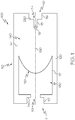
- FIG. 1 One comparative example of an optical connector is schematically illustrated in FIG. 1 .
- the optical connector generally includes a housing with a first end and a second end positioned at opposite ends of an optical axis of the housing.
- the first end of the housing may include an open aperture and the second end of the housing may include a blind aperture such that the optical axis of the housing passes through the open aperture and the blind aperture.
- a chamber may be disposed in an interior volume of the housing such that the optical axis of the housing passes through the chamber.
- the chamber may include a first material disposed therein.
- a light collecting region may be disposed in the interior volume of the housing between the second end of the housing and the chamber such that the optical axis of the housing passes through the light collecting region.
- the light collecting region may be formed from a second, solid material and the blind aperture may be positioned in the light collecting region such that a termination of the blind aperture is spaced apart from the chamber by at least a portion of the second, solid material.
- At least one refracting surface is disposed in the housing between the open aperture and the light collecting region such that the optical axis of the housing passes through the at least one refracting surface.
- the optical connector 100 comprises a housing 110 having an open aperture 113 at a first end 111 and a blind aperture 114 at a second end 112.
- the first end 111 and the second end 112 are positioned at opposite ends of an optical axis 190 of the optical connector 100 (i.e., the optical axis of the housing 110).
- the open aperture 113 and the blind aperture 114 are positioned such that the optical axis 190 passes through and is coaxial with the open aperture 113 and the blind aperture 114.
- the optical connector 100 further comprises a chamber 130, a light collecting region 140, and a refracting surface 150, each positioned in the interior volume 120 of the housing 110 along the optical axis 190.
- the chamber 130 is disposed adjacent to the open aperture 113 and the light collecting region 140 is disposed adjacent to the blind aperture 114. Further, the refracting surface 150 is disposed between the chamber 130 and the light collecting 140.
- the optical connector 100 may be monolithic, such as when the optical connector 100 is molded or formed from a single piece of material.
- a single piece of transparent material may be formed to include the individual components of the optical connector 100, such as the housing 110, the open aperture 113, the blind aperture 114, the chamber 130, the light collecting region 140, and the refracting surface 150.
- the optical connector 100 may be formed from multiple individual components assembled together.
- the housing 110 may be formed in two discrete halves which are coupled together with one or more fasteners and/or adhesives.
- the housing 110 of the optical connector 100 may be made from an optically transparent material.
- the housing 110 may be formed from a molded polymer manufactured using any known polymeric molding technology, such as, for example, injection molding.
- the molded polymer of the housing 110 may comprise an acrylic polymer, PMMA, polycarbonate, polystyrene, acrylic, cyclic olefin polymer (e.g. ZeonexTM), UltemTM, clear PVC, or clarified polyolefins.
- the housing 110 may be made from glass.
- the glass may be shaped into the housing using precision grinding and polishing methods, single point diamond turning methods, molding to an optical finish, molding to a near-net shape and finishing via grind and polish, press-molding a composite glass forming powder into a near-net shape and consolidating (i.e. melting) at high temperature or via hot isostatic pressing (HIP) to convert to a solid glass housing, or other, similar methods used for shaping glass.
- the material of the housing 110 may be transparent, formable, and optically transmissive, allowing light to pass from a first end 111 to a second end 112.
- the housing 110 may be 10-30 mm in length, for example 20 mm.
- the housing 110 may be 5-15 mm in diameter, for example 10 mm.
- the housing 110 can align a light source and an optical fiber at opposing ends of the housing 110 to facilitate coupling of light from the light source to the optical fiber, such as the embodiments and examples depicted in FIGS 2-5 , below.
- the housing 110 comprises an open aperture 113 located at the first end 111 of the housing 110.
- the open aperture 113 comprises a receiving portion 117 for receiving and securing a light source 160 ( FIG. 2 ) in the housing 110.
- the open aperture 113 may also include a seat 240 disposed between the receiving portion 117 and the chamber 130.
- the seat 240 may be used as a datum that regulates the depth of insertion of the light source 160 in the housing 110 and also provides a bonding surface to which the light source 160 may be mechanically or adhesively coupled.
- the housing 110 further comprises a blind aperture 114 located at the second end 112 of the housing 110.
- the blind aperture 114 extends from the second end 112 of the housing 110 into the light collecting region 140 and terminates in the light collecting region 140.
- the depth of the blind aperture 114 may be from about 1 mm to about 2 mm, for example, about 1.5 mm.
- the blind aperture 114 may be constructed to receive various portions of an optical fiber 170 ( FIG. 2 ). When the optical fiber 170 is positioned in the blind aperture 114, an input face 171 of the optical fiber 170 is generally co-located or coincident with the termination of the blind aperture 114 in the light collecting region 140 of the housing 110.
- the blind aperture 114 may comprise a cladding receiving portion 116, a core receiving portion 115, and a fiber seat 250 disposed between the cladding receiving portion 116 and the core receiving portion 115.
- the core receiving portion 115 is sized to receive a stripped core portion (i.e., the waveguide 172) of an optical fiber 170 while the cladding receiving portion 116 is sized to receive a portion of the optical fiber 170 with the cladding and/or coating intact around the core portion.
- the diameter of the cladding receiving portion 116 is larger than the diameter of the core receiving portion 115.
- the core receiving portion 115 may have a diameter from about 100 ⁇ m to about 300 ⁇ m, such as, for example about 200 ⁇ m, and the cladding receiving portion 116 may have a diameter from about 300 ⁇ m to about 700 ⁇ m, such as, for example about 500 ⁇ m.
- the cladding receiving portion 116 and the core receiving portion 115 may have substantially the same diameters, such as when the blind aperture 114 is sized to receive a stripped optical fiber or, alternatively, a clad optical fiber.
- the blind aperture 114 may not comprise a fiber seat 250.
- the housing 110 may comprise a mechanical retention device (not shown) for retaining the optical fiber 170 in the blind aperture 114.
- the blind aperture 114 may comprise one or more resilient barbs extending from the sidewall of the blind aperture 114 in a direction towards the termination of the blind aperture 114 in the light collecting region 140. The resilient barbs flex towards the walls of the blind aperture 114 to allow an optical fiber 170 to be inserted in the blind aperture 114 and engage with the cladding and/or core portion of the optical fiber 170 to resist the withdrawal of the optical fiber 170 from the blind aperture 114.
- the core receiving portion 115, the cladding receiving portion 116, or both may include a gripping member.
- one or more cams (not shown) which can be rotated to increase or decrease the diameter of the core receiving portion 115 and the cladding receiving portion 116 of the blind aperture 114 may be positioned in the blind aperture 114.
- the cams may be biased into contact with the cladding and/or coating of the optical fiber 170 when the optical fiber 170 is installed in the blind aperture 114, thereby preventing the optical fiber 170 from being withdrawn.
- the engagement with the optical fiber 170 may be released with a push button located on the housing 110 which, when depressed, pivots the cam out of engagement with the optical fiber 170.
- the blind aperture 114 may further comprise one or more levered grippers (not shown), that can engage and disengage with the core receiving portion 115 or the cladding receiving portion 116.
- One end of a levered gripper can press into the core receiving portion 115 or the cladding receiving portion 116 engaging the blind aperture 114 and an optical fiber 170.
- Multiple levered grippers can be positioned around the blind aperture 114 and can be individually biased into contact with the core receiving portion 115 or the cladding receiving portion 116. Alternatively, multiple levered grippers can be biased into contact with the core receiving portion 115 or the cladding receiving portion 116 by a single actuator.
- the blind aperture 114 may be coupled to an optical fiber 170 with an interference fit.
- the diameter of the core receiving portion 115 can be substantially equivalent to the diameter of the waveguide 172 of the optical fiber 170 and the diameter of the cladding receiving portion 116 can be substantially equivalent to the diameter of the cladding layer 173 of the optical fiber 170. Friction between the surfaces of the blind aperture 114 and the optical fiber 170 retains the optical fiber 170 within the blind aperture 114.
- the housing 110 may also include a light collecting region 140 disposed between the chamber 130 and the blind aperture 114 in the interior volume 120 of the housing 110 such that the optical axis 190 passes through the light collecting region 140.
- the light collecting region 140 can be positioned in the housing 110 such that the termination of the blind aperture 114 is substantially co-located with a portion of the light collecting region 140 and spaced apart from the chamber 130 by at least a portion of the material 141 of the light collecting region 140.
- the light collecting region 140 is integrally formed with the housing 110, such as when the housing 110 and the light collecting region 140 are molded from the same material. Alternatively the light collecting region 140 and the housing 110 may be co-molded from different materials.
- the light collecting region 140 may be from about 5 mm to about 15 mm in length, for example 7 mm or 14 mm.
- the light collecting region 140 functions as a light pipe for guiding light from the chamber 130 to the blind aperture 114.
- the light collecting region 140 is generally formed from a solid, optically transparent material 141 such as, for example, glass or a polymer material such as acrylic polymers, PMMA, polycarbonate, polystyrene, acrylic, cyclic olefin polymer (e.g. ZeonexTM) UltemvTM, clear PVC, or clarified polyolefins.
- the material 141 of the light collecting region 140 is different from the material 131 of the chamber 130 and, in some examples, can be the same material as the material of the housing 110.
- the housing 110 may further include a chamber 130 positioned adjacent to the open aperture 113 in an interior volume 120 of the housing 110 between the open aperture 113 and the light collecting region 140 such that the optical axis 190 passes through the chamber 130.
- the termination of the chamber 130 proximate the light collecting region 140 is substantially co-located with the refracting surface 150.
- the chamber 130 may be from about 5 mm to about 15 mm in length, for example 7 mm or 14 mm.
- the chamber 130 generally comprises a hollow or open volume within the interior volume 120 of the housing 110 which contains a material 131 different than that of the housing 110 and the material 141 of the light collecting region 140.
- the material 131 of the chamber 130 comprises a gas, such as air and the material 141 of the light collecting region 140 comprises a second, solid material.
- the material 131 of the chamber 130 may comprise an index matching material, such as an index matching gel, oil, or a cured optical adhesive.
- the index matching material may be a material which is compositionally different than the material 141 of the light collecting region 140, but has an index of refraction that is similar to or the same as the index of refraction of the material 141 of the light collecting region 140 in order to assist in collecting the light from the chamber 130 and propagating the light through the light collecting region 140.
- the material 141 of the light collecting region 140 may comprise a silicon polymer having an index of refraction of 1.5 and the material 131 of the chamber 130 may comprise an index matching material, such as a gel, having an index of refraction of 1.5.
- the material 131 of the chamber 130 may comprise an index matching material having an index of refraction different than the index of refraction of the material 141 of the light collecting region 140.
- the index of refraction of material 131 may be greater than 1 but less than the index of refraction of the material 141 of the light collecting region 140.
- the housing 110 may further comprise at least one refracting surface 150 disposed in the housing 110 between the open aperture 113 and the light collecting region 140 such that the optical axis 190 of the housing 110 passes though and is coaxial with the refracting surface 150.
- the refracting surface 150 is constructed to focus and converge light propagating through the chamber 130 into the light collecting region 140. Accordingly, in some examples, the focal point 151 of the refracting surface 150 is located within the light collecting region 140, such as when the focal point 151 of the refracting surface 150 is coincident or co-located with the termination of the blind aperture 114.
- Co-locating the focal point 151 with the termination of the blind aperture 114 is dependent on the radius of curvature of the refracting surface 150, the index of refraction of the refracting surface 150, the index of refraction of the material 141 of the light collecting region 140, and the length of the light collecting region 140.
- the radius of curvature of the refracting surface 150 should be about 1.25 mm for the focal point of the refracting surface 150 to be substantially co-located with the termination of the blind aperture 114.
- the refracting surface 150 may be the same material 141 as the light collecting region 140, such as a glass or a polymer. Alternatively, the refracting surface 150 may be formed from a different material. In examples where the optical connector 100 is monolithic, the refracting surface 150 may be integral with and molded into the housing 110. In other examples, the refracting surface 150 may be formed separate from the housing 110 and may be coupled to the light collecting region 140 of the housing 110. For example, the refracting surface 150 may be coupled to the light collecting region 140 mechanically, by adhesive, or combinations thereof. The refracting surface 150 may also be co-molded with the housing 110.
- the refracting surface 150 may comprise a lens, for example a spherical lens, an aspherical lens, or a kinoform lens.
- the refracting surface 150 may be a diffractive surface or a planar surface.
- light from a light source coupled to the optical connector 100 can start as divergent light, pass through the refracting surface 150, travel into the light collecting region 140, and continue to diverge toward the termination of the blind aperture 114 which may be substantially co-located with an input face of an optical fiber.
- the housing 110 including the refracting surface 150 and the light collecting region 140, couples a light source to an optical fiber by creating geometric overlap between the optical fiber and the light of the light source at the input face of the optical fiber.
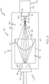
- the optical connector 100 may be utilized in an optical assembly 200 to couple light 161 from a light source 160 into an optical fiber 170.
- the optical assembly 200 may include a light source 160 coupled to the open aperture 113 of the housing 110 and an optical fiber 170 coupled to the blind aperture 114 of the housing 110.
- the light source 160 is coupled to the housing 110 such that light 161 emitted from the light source 160 enters the chamber 130 of the housing 110, travels along an optical path 180, and reaches an input face 171 of the optical fiber 170.
- the optical path 180 is substantially co-located with the optical axis 190 of the housing 110.
- the optical path 180 passes through the chamber 130, the refracting surface 150, and the light collecting region 140.
- Light 161 propagates through the light collecting region 140 from the refracting surface 150 located at one end of the light collecting region 140 to an input face 171 of an optical fiber 170.
- the light 161 from the light source 160 is divergent light that passes through the refracting surface 150 where it is focused onto a focal point 151 of the refracting surface 150.
- the focal point 151 of the refracting surface 150 is substantially co-located with the input face 171 of the optical fiber 170 in the light collecting region 140.
- the optical assembly 200 is schematically depicted with a light source 160 positioned in the receiving portion 117 of the open aperture 113 and engaged with the seat 240 of the open aperture 113.
- the light source 160 may be a laser diode, an LED, a red-green-blue (RGB) diode, or a white light source.
- the light source 160 may comprise multiple emitters, such as, for example, multiple laser diodes, multiple LEDs, or individual red, green, and blue diodes.
- the light source 160 may be packaged in a standardized transistor-outline (TO) can package to facilitate coupling with the open aperture 113.
- TO transistor-outline
- the light source 160 may be engaged with the receiving portion 117 through an interference fit, a mechanical connection, adhesives, or combinations thereof.
- the receiving portion 117 centers the light source 160 in the open aperture 113 such that the light source 160 emits light 161 along the optical axis 190 from the first end 111 to the second end 112 of the housing 110.
- the receiving portion 117 also positions the light source 160 such that the light source 160 is spaced apart from the light collecting region 140 and at least one refracting surface 150 by the length of the chamber 130.
- the optical assembly 200 is schematically depicted with an optical fiber 170 positioned in the blind aperture 114 of the housing 110.
- the optical fiber 170 may engage with the blind aperture 114 using an interference fit, a mechanical connection (i.e., utilizing set screws, a threaded can package or the like), an adhesive, or combinations thereof.
- the core receiving portion 115 of the blind aperture 114 can engage with the waveguide 172 of the optical fiber 170.
- the cladding layer 173 and the coating layer 174 of the optical fiber 170 can be removed from a portion of the optical fiber 170 exposing the waveguide 172 which is inserted in the core receiving portion 115 of the blind aperture 114.
- the waveguide 172 directly engages with the core receiving portion 115 of the blind aperture 114.
- the coating layer 174 is removed from a portion of the optical fiber 170 adjacent to the exposed waveguide 172, exposing the cladding layer 173 which enters the cladding receiving portion 116 of the blind aperture 114 when the optical fiber 170 is inserted into the blind aperture 114 and engages directly with the cladding receiving portion 116.
- a portion of the optical fiber 170 may be bonded to a portion of the blind aperture 114.
- the cladding of the optical fiber 170 may be adhesively bonded to the fiber seat 250 to retain the optical fiber 170 in the blind aperture 114.
- the input face 171 of the optical fiber 170 is generally co-located or coincident with the termination of the blind aperture 114 in the light collecting region 140 of the housing 110.
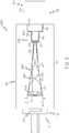
- the optical connector 300 includes a housing 110 with a first end 111 and a second end 112 positioned at opposite ends of an optical axis 190 of the housing 110.
- a collimating lens 550 and a chamber 130 are disposed in an interior volume 120 of the housing 110.
- the chamber 130 comprises a sidewall 220.
- the chamber 130 may be substantially circular in cross section and, as such, comprises a single sidewall 220 which defines the chamber 130.
- the chamber 130 may further comprise a reflecting material 210 positioned on the sidewall 220 of the chamber 130.
- the sidewall 220 may be mirrored with a highly reflective dielectric reflector or metallic coating, such as silver, gold, aluminum or the like.
- the housing 110 may be made from a monolithic piece of material, for example, a single piece of polymer or glass. Alternatively, the housing 110 may be constructed from discrete segments coupled together with adhesives and/or mechanical fasteners. In a multiple piece embodiment, the housing 110 may comprise a first half and a second half disposed on opposite sides of a plane parallel to the optical axis 190 of the housing 110 and coupled together along the plane parallel to the optical axis 190.
- the chamber 130 tapers from the first end 111 to the second end 112, creating an optical "funnel" which concentrates light propagating through the chamber 130.
- the chamber 130 can taper from the first end 111 to the second end 112 of the housing 110 such that a first diameter 221 of the chamber 130 at the opening of the chamber 130 and near the first end 111 of the housing 110 is larger than a second diameter 222 of the chamber 130 at the termination of the chamber 130 and near the second end 112 of the housing 110.
- the tapered chamber 130 may be shaped in a variety of parabolic or cone-like configurations.
- the tapered chamber 130 may be an optical horn (i.e., the diameter of the chamber 130 decreases exponentially from the first end 111 to the second end 112), a reverse flare, a truncated cone, a parabola or the like.
- the optical connector 300 can include a first open aperture 113 at the first end 111 of the housing 110 and a second open aperture 230 at the second end 112 of the housing 110.
- the first open aperture 113 may be configured similar to the open aperture described above with respect to FIGS. 1 and 2 .
- the second open aperture 230 may be configured similar to the blind aperture 114 described above with respect to FIGS. 1 and 2 , albeit opening directly into the chamber 130.
- a light source 160 can be coupled to the first open aperture 113 and an optical fiber 170 can be coupled to the second open aperture 230 as described above with respect to FIG. 2 .
- an optical fiber 170 can be positioned in the second open aperture 230 such that an input face 171 of the optical fiber 170 is positioned at the termination of the chamber 130.
- a collimating lens 550 is positioned at the first end 111 of the housing 110 adjacent to the tapered chamber 130.
- the first diameter 221 of the chamber 130 at the opening of the chamber 130 is substantially the same as the diameter of the collimating lens 550.
- the chamber 130 tapers to the second, smaller diameter 222 at the termination of the chamber 130, substantially co-located with the input face 171 of the optical fiber 170.
- the second diameter 222 is smaller than the diameter of both the waveguide 172 and the input face 171 of the optical fiber 170.
- the tapered chamber 130 can concentrate light 161 incident onto a portion of the input face 171 of the optical fiber 170.
- the collimating lens 550 is substantially co-located with the termination of a first open aperture 113 and the opening of the tapered chamber 130.
- the collimating lens 550 may be the same material 141 as the light collecting region 140, such as a glass or a polymer. Alternatively, the collimating lens 550 may be formed from a different material.
- the collimating lens 550 may be integral with and molded into the housing 110.
- the collimating lens 550 may be formed separate from the housing 110 and may be coupled to the first open aperture 113 of the housing 110 or coupled to the sidewalls 220 of the chamber 130, for example, mechanically, by adhesive, or combinations thereof.
- the collimating lens 550 may be positioned between the termination of the first open aperture 113 and the chamber 130.
- the collimating lens 550 may also be co-molded with the housing 110.
- the housing 110 includes an optical axis 190 that passes through the first open aperture 113, the collimating lens 550, the chamber 130, and the second open aperture 230.
- a light source 160 is coupled to the first end 111 of the housing 110 and the light source 160 is powered on
- divergent light 161 emitted from the light source 160 propagates along the optical axis 190 towards an optical fiber coupled to the second end 112 of the housing 110.
- the light 161 passes through the collimating lens 550, collimating and directing the light 161 into the chamber 130.
- the collimated light 161 propagates through the chamber 130, the light 161 is reflected by the reflecting material 210 positioned on the sidewall 220 of the chamber 130.
- the tapered shape of the chamber 130 concentrates the collimated light 161 proximate to the second end 112 of the housing 110 incident onto the input face 171 of the optical fiber 170.
- the optical connector 300 can further include a refracting surface (not shown) and a light collecting region (not shown) positioned between the termination of the chamber 130 and the second end 112, similar to the examples depicted in FIGS 1 and 2 .
- light 161 emitted from the light source 160 passes through the collimating lens 550 and the chamber 130 and reflects from the tapered sidewall 220 of the chamber 130 such that the light 161 is concentrated on the refracting surface.
- the refracting surface focuses the collimated light onto a focal point of the refracting surface in the light collecting region, substantially co-located with an input face 171 of an optical fiber 170, thereby directing a high power density of light 161 incident onto the input face 171 of the optical fiber 170.
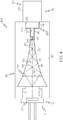
- the optical connector 400 comprises a chamber 130 disposed in the interior volume 120 of the housing 110.
- the chamber 130 tapers from the first end 111 to the second end 112, creating an optical "funnel" which directs light propagating through the chamber 130.
- the chamber 130 can taper from the first end 111 to the second end 112 of the housing 110 such that a first diameter 221 of the chamber 130 at the opening of the chamber 130 and near the first end 111 of the housing 110 is larger than a second diameter 222 of the chamber 130 at the termination of the chamber 130 and near the second end 112 of the housing 110.
- the tapered chamber 130 may be shaped in a variety of parabolic or cone-like configurations.
- the tapered chamber 130 may be a optical horn (i.e., the diameter of the chamber 130 decreases exponentially from the first end 111 to the second end 112), a reverse flare, a truncated cone, a parabola or the like.
- a light source 160 When a light source 160 is coupled to the first end 111 of the housing 110 and the light source 160 is powered on, divergent light 161 emitted from the light source 160 propagates along the optical axis 190 of the optical connector 400 through the chamber 130. As the divergent light 161 propagates through the chamber 130, the light 161 is reflected by the reflecting material 210 positioned on the sidewall 220 of the chamber 130. As the light 161 propagates along the optical path 180, the tapered shape of the chamber 130 concentrates the divergent light 161 proximate to the second end 112 of the housing 110 incident onto the input face 171 of the optical fiber 170.
- the optical connector 400 can further include a refracting surface (not shown) and a light collecting region (not shown) positioned between the termination of the chamber 130 and the second end 112, similar to the examples depicted in FIGS 1 and 2 .
- light 161 emitted from the light source 160 passes through the chamber 130 and reflects from the tapered sidewall 220 of the chamber 130 such that the light 161 is concentrated on the refracting surface.
- the refracting surface focuses the divergent light 161 onto a focal point of the refracting surface in the light collecting region, substantially co-located with an input face 171 of an optical fiber 170, thereby directing a high power density of light 161 incident onto the input face 171 of the optical fiber 170.
- optical connectors described herein may be used to efficiently converge divergent light emitted from a light source onto the input face of an optical fiber.
- Such optical connectors may be readily employed in conjunction with transmission optical fibers and/or light-diffusing fibers used in lighting applications.
- Such optical fibers are particularly well suited for use in lighting applications as the connectors provide a mechanism for quickly coupling and/or decoupling a light source to an optical fiber.
- the optical connectors can be readily manufactured using conventional molding and/or machining techniques, the optical connectors provide a low cost solution for efficiently coupling a light source into an optical fiber without the need for complicated optical components or external alignment equipment.
Description
- The present specification generally relates to devices and assemblies for coupling light sources and optical fibers.
- Optical fibers are used in a wide variety of applications in which light is delivered from a light source to a target region. For example, in some applications, such as lighting, signage, biological applications, etc., light diffusing optical fibers may be utilized such that light propagating through the light diffusing optical fiber is scattered radially outward along a length of the fiber, thereby illuminating the target region along the length of the fiber. A coupling device is preferred to deliver the light from a light source to the light-diffusing fiber or other optical fiber.
- A need exists for alternative optical connectors to connect a variety of light sources to light-diffusing fibers or other optical fibers.
-
US 2011/026937 teaches an optical communications module with a cylindrical optical fiber coupler having an integrally formed imaging lens.US 2005/0121687 teaches an optical device for optical coupling incorporating a resin lens.US 2005/202826 teaches an optical subassembly module with an integral dual lens structure.US 2009/0226139 teaches an optoelectronic subassembly with a barrel and a lens configuration facing the opening of the subassembly. -
EP 1 722 258 teaches an optical radiation coupling module having a moulded guiding element. - The embodiments described herein relate to devices and assemblies for coupling light sources and optical fibers.
- In a first aspect of the invention, there is provided an optical assembly according to claim 1.
- Additional features and advantages of the embodiments described herein will be set forth in the detailed description which follows, and in part will be readily apparent to those skilled in the art from that description or recognized by practicing the embodiments described herein, including the detailed description which follows, the claims, as well as the appended drawings.
- It is to be understood that both the foregoing general description and the following detailed description describe various embodiments and are intended to provide an overview or framework for understanding the nature and character of the claimed subject matter. The accompanying drawings are included to provide a further understanding of the various embodiments, and are incorporated into and constitute a part of this specification. The drawings illustrate the various embodiments described herein, and together with the description, serve to explain the principles and operations of the claimed subject matter.
-
-
FIG. 1 schematically depicts a side view of an optical connector having an open aperture and a blind aperture according to a comparative example; -
FIG. 2 schematically depicts a side view of an optical assembly including an optical connector coupled to a light source and an optical fiber according to a comparative example; -
FIG. 3 schematically depicts a side view of an optical connector having a first open aperture, a second open aperture, and a tapered chamber, according to one or more embodiments shown or described herein; and -
FIG. 4 schematically depicts a side view of an optical connector having a first open aperture, a second open aperture, and a tapered chamber, according to one or more embodiments shown or described herein. - Reference will now be made in detail to embodiments and examples of optical connectors, examples of which are illustrated in the accompanying drawings. Whenever possible, the same reference numerals will be used throughout the drawings to refer to the same or like parts. The optical connectors and assemblies described herein may connect light sources, such as laser diodes or light emitting diodes (LEDs), with an optical fiber, such as a transmission fiber or even a light-diffusing fiber (LDF). One comparative example of an optical connector is schematically illustrated in
FIG. 1 . The optical connector generally includes a housing with a first end and a second end positioned at opposite ends of an optical axis of the housing. The first end of the housing may include an open aperture and the second end of the housing may include a blind aperture such that the optical axis of the housing passes through the open aperture and the blind aperture. A chamber may be disposed in an interior volume of the housing such that the optical axis of the housing passes through the chamber. The chamber may include a first material disposed therein. A light collecting region may be disposed in the interior volume of the housing between the second end of the housing and the chamber such that the optical axis of the housing passes through the light collecting region. The light collecting region may be formed from a second, solid material and the blind aperture may be positioned in the light collecting region such that a termination of the blind aperture is spaced apart from the chamber by at least a portion of the second, solid material. At least one refracting surface is disposed in the housing between the open aperture and the light collecting region such that the optical axis of the housing passes through the at least one refracting surface. Various embodiments of optical connectors will be described in further detail herein with specific reference to the appended drawings. - Referring now to
FIG. 1 , a side view of anoptical connector 100 is schematically depicted. Theoptical connector 100 comprises ahousing 110 having anopen aperture 113 at afirst end 111 and ablind aperture 114 at asecond end 112. Thefirst end 111 and thesecond end 112 are positioned at opposite ends of anoptical axis 190 of the optical connector 100 (i.e., the optical axis of the housing 110). In some examples, theopen aperture 113 and theblind aperture 114 are positioned such that theoptical axis 190 passes through and is coaxial with theopen aperture 113 and theblind aperture 114. Theoptical connector 100 further comprises achamber 130, alight collecting region 140, and arefracting surface 150, each positioned in theinterior volume 120 of thehousing 110 along theoptical axis 190. Thechamber 130 is disposed adjacent to theopen aperture 113 and thelight collecting region 140 is disposed adjacent to theblind aperture 114. Further, the refractingsurface 150 is disposed between thechamber 130 and the light collecting 140. - In some examples, the
optical connector 100 may be monolithic, such as when theoptical connector 100 is molded or formed from a single piece of material. For example, a single piece of transparent material may be formed to include the individual components of theoptical connector 100, such as thehousing 110, theopen aperture 113, theblind aperture 114, thechamber 130, thelight collecting region 140, and therefracting surface 150. Alternatively, theoptical connector 100 may be formed from multiple individual components assembled together. For example, thehousing 110 may be formed in two discrete halves which are coupled together with one or more fasteners and/or adhesives. - Referring still to
FIG. 1 , thehousing 110 of theoptical connector 100 may be made from an optically transparent material. For example, in some examples, thehousing 110 may be formed from a molded polymer manufactured using any known polymeric molding technology, such as, for example, injection molding. The molded polymer of thehousing 110 may comprise an acrylic polymer, PMMA, polycarbonate, polystyrene, acrylic, cyclic olefin polymer (e.g. Zeonex™), Ultem™, clear PVC, or clarified polyolefins. Alternatively, thehousing 110 may be made from glass. In these examples, the glass may be shaped into the housing using precision grinding and polishing methods, single point diamond turning methods, molding to an optical finish, molding to a near-net shape and finishing via grind and polish, press-molding a composite glass forming powder into a near-net shape and consolidating (i.e. melting) at high temperature or via hot isostatic pressing (HIP) to convert to a solid glass housing, or other, similar methods used for shaping glass. The material of thehousing 110 may be transparent, formable, and optically transmissive, allowing light to pass from afirst end 111 to asecond end 112. In examples, thehousing 110 may be 10-30 mm in length, for example 20 mm. In examples, thehousing 110 may be 5-15 mm in diameter, for example 10 mm. In examples, thehousing 110 can align a light source and an optical fiber at opposing ends of thehousing 110 to facilitate coupling of light from the light source to the optical fiber, such as the embodiments and examples depicted inFIGS 2-5 , below. - The
housing 110 comprises anopen aperture 113 located at thefirst end 111 of thehousing 110. Theopen aperture 113 comprises a receivingportion 117 for receiving and securing a light source 160 (FIG. 2 ) in thehousing 110. Theopen aperture 113 may also include aseat 240 disposed between thereceiving portion 117 and thechamber 130. Theseat 240 may be used as a datum that regulates the depth of insertion of thelight source 160 in thehousing 110 and also provides a bonding surface to which thelight source 160 may be mechanically or adhesively coupled. - In some examples, the
housing 110 further comprises ablind aperture 114 located at thesecond end 112 of thehousing 110. Theblind aperture 114 extends from thesecond end 112 of thehousing 110 into thelight collecting region 140 and terminates in thelight collecting region 140. In some examples, the depth of theblind aperture 114 may be from about 1 mm to about 2 mm, for example, about 1.5 mm. Theblind aperture 114 may be constructed to receive various portions of an optical fiber 170 (FIG. 2 ). When theoptical fiber 170 is positioned in theblind aperture 114, aninput face 171 of theoptical fiber 170 is generally co-located or coincident with the termination of theblind aperture 114 in thelight collecting region 140 of thehousing 110. For example, in some examples, theblind aperture 114 may comprise acladding receiving portion 116, acore receiving portion 115, and afiber seat 250 disposed between thecladding receiving portion 116 and thecore receiving portion 115. In some examples, thecore receiving portion 115 is sized to receive a stripped core portion (i.e., the waveguide 172) of anoptical fiber 170 while thecladding receiving portion 116 is sized to receive a portion of theoptical fiber 170 with the cladding and/or coating intact around the core portion. - Accordingly, it should be understood that, in some examples, the diameter of the
cladding receiving portion 116 is larger than the diameter of thecore receiving portion 115. For example, thecore receiving portion 115 may have a diameter from about 100 µm to about 300 µm, such as, for example about 200 µm, and thecladding receiving portion 116 may have a diameter from about 300 µm to about 700 µm, such as, for example about 500 µm. In some examples (not shown), thecladding receiving portion 116 and thecore receiving portion 115 may have substantially the same diameters, such as when theblind aperture 114 is sized to receive a stripped optical fiber or, alternatively, a clad optical fiber. When the diameters of thecladding receiving portion 116 and thecore receiving portion 115 are substantially equivalent, theblind aperture 114 may not comprise afiber seat 250. - The
housing 110 may comprise a mechanical retention device (not shown) for retaining theoptical fiber 170 in theblind aperture 114. For example, in one example (not shown), theblind aperture 114 may comprise one or more resilient barbs extending from the sidewall of theblind aperture 114 in a direction towards the termination of theblind aperture 114 in thelight collecting region 140. The resilient barbs flex towards the walls of theblind aperture 114 to allow anoptical fiber 170 to be inserted in theblind aperture 114 and engage with the cladding and/or core portion of theoptical fiber 170 to resist the withdrawal of theoptical fiber 170 from theblind aperture 114. - Alternatively, the
core receiving portion 115, thecladding receiving portion 116, or both may include a gripping member. For example, one or more cams (not shown) which can be rotated to increase or decrease the diameter of thecore receiving portion 115 and thecladding receiving portion 116 of theblind aperture 114 may be positioned in theblind aperture 114. The cams may be biased into contact with the cladding and/or coating of theoptical fiber 170 when theoptical fiber 170 is installed in theblind aperture 114, thereby preventing theoptical fiber 170 from being withdrawn. The engagement with theoptical fiber 170 may be released with a push button located on thehousing 110 which, when depressed, pivots the cam out of engagement with theoptical fiber 170. In an alternative example, theblind aperture 114 may further comprise one or more levered grippers (not shown), that can engage and disengage with thecore receiving portion 115 or thecladding receiving portion 116. One end of a levered gripper can press into thecore receiving portion 115 or thecladding receiving portion 116 engaging theblind aperture 114 and anoptical fiber 170. Multiple levered grippers can be positioned around theblind aperture 114 and can be individually biased into contact with thecore receiving portion 115 or thecladding receiving portion 116. Alternatively, multiple levered grippers can be biased into contact with thecore receiving portion 115 or thecladding receiving portion 116 by a single actuator. - In other examples, the
blind aperture 114 may be coupled to anoptical fiber 170 with an interference fit. In an interference fit, the diameter of thecore receiving portion 115 can be substantially equivalent to the diameter of thewaveguide 172 of theoptical fiber 170 and the diameter of thecladding receiving portion 116 can be substantially equivalent to the diameter of thecladding layer 173 of theoptical fiber 170. Friction between the surfaces of theblind aperture 114 and theoptical fiber 170 retains theoptical fiber 170 within theblind aperture 114. - Referring still to
FIG. 1 , thehousing 110 may also include alight collecting region 140 disposed between thechamber 130 and theblind aperture 114 in theinterior volume 120 of thehousing 110 such that theoptical axis 190 passes through thelight collecting region 140. Thelight collecting region 140 can be positioned in thehousing 110 such that the termination of theblind aperture 114 is substantially co-located with a portion of thelight collecting region 140 and spaced apart from thechamber 130 by at least a portion of thematerial 141 of thelight collecting region 140. In some examples, thelight collecting region 140 is integrally formed with thehousing 110, such as when thehousing 110 and thelight collecting region 140 are molded from the same material. Alternatively thelight collecting region 140 and thehousing 110 may be co-molded from different materials. In some examples, thelight collecting region 140 may be from about 5 mm to about 15 mm in length, for example 7 mm or 14 mm. - In the example shown in
FIG. 1 , thelight collecting region 140 functions as a light pipe for guiding light from thechamber 130 to theblind aperture 114. As such, thelight collecting region 140 is generally formed from a solid, opticallytransparent material 141 such as, for example, glass or a polymer material such as acrylic polymers, PMMA, polycarbonate, polystyrene, acrylic, cyclic olefin polymer (e.g. Zeonex™) Ultemv™, clear PVC, or clarified polyolefins. In examples described herein, thematerial 141 of thelight collecting region 140 is different from thematerial 131 of thechamber 130 and, in some examples, can be the same material as the material of thehousing 110. - Referring still to
FIG. 1 , thehousing 110 may further include achamber 130 positioned adjacent to theopen aperture 113 in aninterior volume 120 of thehousing 110 between theopen aperture 113 and thelight collecting region 140 such that theoptical axis 190 passes through thechamber 130. In some examples, the termination of thechamber 130 proximate thelight collecting region 140 is substantially co-located with the refractingsurface 150. Thechamber 130 may be from about 5 mm to about 15 mm in length, for example 7 mm or 14 mm. Thechamber 130 generally comprises a hollow or open volume within theinterior volume 120 of thehousing 110 which contains amaterial 131 different than that of thehousing 110 and thematerial 141 of thelight collecting region 140. In some examples, thematerial 131 of thechamber 130 comprises a gas, such as air and thematerial 141 of thelight collecting region 140 comprises a second, solid material. - In some examples, the
material 131 of thechamber 130 may comprise an index matching material, such as an index matching gel, oil, or a cured optical adhesive. The index matching material may be a material which is compositionally different than thematerial 141 of thelight collecting region 140, but has an index of refraction that is similar to or the same as the index of refraction of thematerial 141 of thelight collecting region 140 in order to assist in collecting the light from thechamber 130 and propagating the light through thelight collecting region 140. As a non-limiting example, thematerial 141 of thelight collecting region 140 may comprise a silicon polymer having an index of refraction of 1.5 and thematerial 131 of thechamber 130 may comprise an index matching material, such as a gel, having an index of refraction of 1.5. In other examples, thematerial 131 of thechamber 130 may comprise an index matching material having an index of refraction different than the index of refraction of thematerial 141 of thelight collecting region 140. For example, the index of refraction ofmaterial 131 may be greater than 1 but less than the index of refraction of thematerial 141 of thelight collecting region 140. - Referring still to
FIG. 1 , thehousing 110 may further comprise at least one refractingsurface 150 disposed in thehousing 110 between theopen aperture 113 and thelight collecting region 140 such that theoptical axis 190 of thehousing 110 passes though and is coaxial with the refractingsurface 150. The refractingsurface 150 is constructed to focus and converge light propagating through thechamber 130 into thelight collecting region 140. Accordingly, in some examples, thefocal point 151 of the refractingsurface 150 is located within thelight collecting region 140, such as when thefocal point 151 of the refractingsurface 150 is coincident or co-located with the termination of theblind aperture 114. Co-locating thefocal point 151 with the termination of theblind aperture 114 is dependent on the radius of curvature of the refractingsurface 150, the index of refraction of the refractingsurface 150, the index of refraction of thematerial 141 of thelight collecting region 140, and the length of thelight collecting region 140. For example, if thematerial 141 of thelight collecting region 140 and the material of the refractingsurface 150 comprise a polymer having a index of refraction of 1.5 and the length of the light collecting region is 5 mm, than the radius of curvature of the refractingsurface 150 should be about 1.25 mm for the focal point of the refractingsurface 150 to be substantially co-located with the termination of theblind aperture 114. - In some examples, the refracting
surface 150 may be thesame material 141 as thelight collecting region 140, such as a glass or a polymer. Alternatively, the refractingsurface 150 may be formed from a different material. In examples where theoptical connector 100 is monolithic, the refractingsurface 150 may be integral with and molded into thehousing 110. In other examples, the refractingsurface 150 may be formed separate from thehousing 110 and may be coupled to thelight collecting region 140 of thehousing 110. For example, the refractingsurface 150 may be coupled to thelight collecting region 140 mechanically, by adhesive, or combinations thereof. The refractingsurface 150 may also be co-molded with thehousing 110. - In some examples, the refracting
surface 150 may comprise a lens, for example a spherical lens, an aspherical lens, or a kinoform lens. In other examples, the refractingsurface 150 may be a diffractive surface or a planar surface. When the refractingsurface 150 is planar, light from a light source coupled to theoptical connector 100 can start as divergent light, pass through the refractingsurface 150, travel into thelight collecting region 140, and continue to diverge toward the termination of theblind aperture 114 which may be substantially co-located with an input face of an optical fiber. In this example, thehousing 110, including the refractingsurface 150 and thelight collecting region 140, couples a light source to an optical fiber by creating geometric overlap between the optical fiber and the light of the light source at the input face of the optical fiber. - Referring now to
FIG. 2 , theoptical connector 100 may be utilized in anoptical assembly 200 to couple light 161 from alight source 160 into anoptical fiber 170. For example, theoptical assembly 200 may include alight source 160 coupled to theopen aperture 113 of thehousing 110 and anoptical fiber 170 coupled to theblind aperture 114 of thehousing 110. In this example, thelight source 160 is coupled to thehousing 110 such thatlight 161 emitted from thelight source 160 enters thechamber 130 of thehousing 110, travels along anoptical path 180, and reaches aninput face 171 of theoptical fiber 170. Theoptical path 180 is substantially co-located with theoptical axis 190 of thehousing 110. In some examples, theoptical path 180 passes through thechamber 130, the refractingsurface 150, and thelight collecting region 140.Light 161 propagates through thelight collecting region 140 from the refractingsurface 150 located at one end of thelight collecting region 140 to aninput face 171 of anoptical fiber 170. In some examples, the light 161 from thelight source 160 is divergent light that passes through the refractingsurface 150 where it is focused onto afocal point 151 of the refractingsurface 150. For example, in some examples, thefocal point 151 of the refractingsurface 150 is substantially co-located with theinput face 171 of theoptical fiber 170 in thelight collecting region 140. - Referring still to
FIG. 2 , theoptical assembly 200 is schematically depicted with alight source 160 positioned in the receivingportion 117 of theopen aperture 113 and engaged with theseat 240 of theopen aperture 113. In the examples described herein, thelight source 160 may be a laser diode, an LED, a red-green-blue (RGB) diode, or a white light source. In some examples, thelight source 160 may comprise multiple emitters, such as, for example, multiple laser diodes, multiple LEDs, or individual red, green, and blue diodes. In some examples, thelight source 160 may be packaged in a standardized transistor-outline (TO) can package to facilitate coupling with theopen aperture 113. In some examples, thelight source 160 may be engaged with the receivingportion 117 through an interference fit, a mechanical connection, adhesives, or combinations thereof. The receivingportion 117 centers thelight source 160 in theopen aperture 113 such that thelight source 160 emits light 161 along theoptical axis 190 from thefirst end 111 to thesecond end 112 of thehousing 110. The receivingportion 117 also positions thelight source 160 such that thelight source 160 is spaced apart from thelight collecting region 140 and at least one refractingsurface 150 by the length of thechamber 130. - Referring still to
FIG. 2 , theoptical assembly 200 is schematically depicted with anoptical fiber 170 positioned in theblind aperture 114 of thehousing 110. Theoptical fiber 170 may engage with theblind aperture 114 using an interference fit, a mechanical connection (i.e., utilizing set screws, a threaded can package or the like), an adhesive, or combinations thereof. For example, in some examples, thecore receiving portion 115 of theblind aperture 114 can engage with thewaveguide 172 of theoptical fiber 170. In this example, thecladding layer 173 and thecoating layer 174 of theoptical fiber 170 can be removed from a portion of theoptical fiber 170 exposing thewaveguide 172 which is inserted in thecore receiving portion 115 of theblind aperture 114. By removing thecladding layer 173 and thecoating layer 174, thewaveguide 172 directly engages with thecore receiving portion 115 of theblind aperture 114. In this example, thecoating layer 174 is removed from a portion of theoptical fiber 170 adjacent to the exposedwaveguide 172, exposing thecladding layer 173 which enters thecladding receiving portion 116 of theblind aperture 114 when theoptical fiber 170 is inserted into theblind aperture 114 and engages directly with thecladding receiving portion 116. A portion of theoptical fiber 170 may be bonded to a portion of theblind aperture 114. For example, in some examples, the cladding of theoptical fiber 170 may be adhesively bonded to thefiber seat 250 to retain theoptical fiber 170 in theblind aperture 114. In the examples described herein, when theoptical fiber 170 is positioned in theblind aperture 114, theinput face 171 of theoptical fiber 170 is generally co-located or coincident with the termination of theblind aperture 114 in thelight collecting region 140 of thehousing 110. - Referring now to
FIG. 3 , an embodiment of anoptical connector 300 is depicted. In this embodiment, theoptical connector 300 includes ahousing 110 with afirst end 111 and asecond end 112 positioned at opposite ends of anoptical axis 190 of thehousing 110. Acollimating lens 550 and achamber 130 are disposed in aninterior volume 120 of thehousing 110. Thechamber 130 comprises asidewall 220. For example, thechamber 130 may be substantially circular in cross section and, as such, comprises asingle sidewall 220 which defines thechamber 130. Thechamber 130 may further comprise a reflectingmaterial 210 positioned on thesidewall 220 of thechamber 130. For example, in some embodiments, thesidewall 220 may be mirrored with a highly reflective dielectric reflector or metallic coating, such as silver, gold, aluminum or the like. In some embodiments, thehousing 110 may be made from a monolithic piece of material, for example, a single piece of polymer or glass. Alternatively, thehousing 110 may be constructed from discrete segments coupled together with adhesives and/or mechanical fasteners. In a multiple piece embodiment, thehousing 110 may comprise a first half and a second half disposed on opposite sides of a plane parallel to theoptical axis 190 of thehousing 110 and coupled together along the plane parallel to theoptical axis 190. - Still referring to
FIG. 3 , thechamber 130 tapers from thefirst end 111 to thesecond end 112, creating an optical "funnel" which concentrates light propagating through thechamber 130. For example, thechamber 130 can taper from thefirst end 111 to thesecond end 112 of thehousing 110 such that afirst diameter 221 of thechamber 130 at the opening of thechamber 130 and near thefirst end 111 of thehousing 110 is larger than asecond diameter 222 of thechamber 130 at the termination of thechamber 130 and near thesecond end 112 of thehousing 110. Thetapered chamber 130 may be shaped in a variety of parabolic or cone-like configurations. For example, thetapered chamber 130 may be an optical horn (i.e., the diameter of thechamber 130 decreases exponentially from thefirst end 111 to the second end 112), a reverse flare, a truncated cone, a parabola or the like. - Still referring to
FIG. 3 , in one embodiment, theoptical connector 300 can include a firstopen aperture 113 at thefirst end 111 of thehousing 110 and a secondopen aperture 230 at thesecond end 112 of thehousing 110. The firstopen aperture 113 may be configured similar to the open aperture described above with respect toFIGS. 1 and2 . The secondopen aperture 230 may be configured similar to theblind aperture 114 described above with respect toFIGS. 1 and2 , albeit opening directly into thechamber 130. Alight source 160 can be coupled to the firstopen aperture 113 and anoptical fiber 170 can be coupled to the secondopen aperture 230 as described above with respect toFIG. 2 . For example, anoptical fiber 170 can be positioned in the secondopen aperture 230 such that aninput face 171 of theoptical fiber 170 is positioned at the termination of thechamber 130. - Still referring to
FIG. 3 , in some embodiments, acollimating lens 550 is positioned at thefirst end 111 of thehousing 110 adjacent to thetapered chamber 130. Thefirst diameter 221 of thechamber 130 at the opening of thechamber 130 is substantially the same as the diameter of thecollimating lens 550. Thechamber 130 tapers to the second,smaller diameter 222 at the termination of thechamber 130, substantially co-located with theinput face 171 of theoptical fiber 170. Thesecond diameter 222 is smaller than the diameter of both thewaveguide 172 and theinput face 171 of theoptical fiber 170. In this embodiment, thetapered chamber 130 can concentrate light 161 incident onto a portion of theinput face 171 of theoptical fiber 170. - The
collimating lens 550 is substantially co-located with the termination of a firstopen aperture 113 and the opening of the taperedchamber 130. Thecollimating lens 550 may be thesame material 141 as thelight collecting region 140, such as a glass or a polymer. Alternatively, thecollimating lens 550 may be formed from a different material. In embodiments where theoptical connector 300 is monolithic, thecollimating lens 550 may be integral with and molded into thehousing 110. In other embodiments, thecollimating lens 550 may be formed separate from thehousing 110 and may be coupled to the firstopen aperture 113 of thehousing 110 or coupled to thesidewalls 220 of thechamber 130, for example, mechanically, by adhesive, or combinations thereof. Thecollimating lens 550 may be positioned between the termination of the firstopen aperture 113 and thechamber 130. Thecollimating lens 550 may also be co-molded with thehousing 110. - Still referring to
FIG. 3 , thehousing 110 includes anoptical axis 190 that passes through the firstopen aperture 113, thecollimating lens 550, thechamber 130, and the secondopen aperture 230. When alight source 160 is coupled to thefirst end 111 of thehousing 110 and thelight source 160 is powered on,divergent light 161 emitted from thelight source 160 propagates along theoptical axis 190 towards an optical fiber coupled to thesecond end 112 of thehousing 110. The light 161 passes through thecollimating lens 550, collimating and directing the light 161 into thechamber 130. As the collimatedlight 161 propagates through thechamber 130, the light 161 is reflected by the reflectingmaterial 210 positioned on thesidewall 220 of thechamber 130. As the collimatedlight 161 propagates along theoptical path 180, the tapered shape of thechamber 130 concentrates the collimated light 161 proximate to thesecond end 112 of thehousing 110 incident onto theinput face 171 of theoptical fiber 170. - In embodiments, the
optical connector 300 can further include a refracting surface (not shown) and a light collecting region (not shown) positioned between the termination of thechamber 130 and thesecond end 112, similar to the examples depicted inFIGS 1 and2 . In this embodiment, light 161 emitted from thelight source 160 passes through thecollimating lens 550 and thechamber 130 and reflects from the taperedsidewall 220 of thechamber 130 such that the light 161 is concentrated on the refracting surface. The refracting surface focuses the collimated light onto a focal point of the refracting surface in the light collecting region, substantially co-located with aninput face 171 of anoptical fiber 170, thereby directing a high power density oflight 161 incident onto theinput face 171 of theoptical fiber 170. - Referring now to
FIG. 4 , another embodiment of anoptical connector 400 is depicted. In this embodiment, theoptical connector 400 comprises achamber 130 disposed in theinterior volume 120 of thehousing 110. Thechamber 130 tapers from thefirst end 111 to thesecond end 112, creating an optical "funnel" which directs light propagating through thechamber 130. For example, thechamber 130 can taper from thefirst end 111 to thesecond end 112 of thehousing 110 such that afirst diameter 221 of thechamber 130 at the opening of thechamber 130 and near thefirst end 111 of thehousing 110 is larger than asecond diameter 222 of thechamber 130 at the termination of thechamber 130 and near thesecond end 112 of thehousing 110. Thetapered chamber 130 may be shaped in a variety of parabolic or cone-like configurations. For example, thetapered chamber 130 may be a optical horn (i.e., the diameter of thechamber 130 decreases exponentially from thefirst end 111 to the second end 112), a reverse flare, a truncated cone, a parabola or the like. - When a
light source 160 is coupled to thefirst end 111 of thehousing 110 and thelight source 160 is powered on,divergent light 161 emitted from thelight source 160 propagates along theoptical axis 190 of theoptical connector 400 through thechamber 130. As thedivergent light 161 propagates through thechamber 130, the light 161 is reflected by the reflectingmaterial 210 positioned on thesidewall 220 of thechamber 130. As the light 161 propagates along theoptical path 180, the tapered shape of thechamber 130 concentrates thedivergent light 161 proximate to thesecond end 112 of thehousing 110 incident onto theinput face 171 of theoptical fiber 170. - In some embodiments (not shown), the
optical connector 400 can further include a refracting surface (not shown) and a light collecting region (not shown) positioned between the termination of thechamber 130 and thesecond end 112, similar to the examples depicted inFIGS 1 and2 . In this embodiment, light 161 emitted from thelight source 160 passes through thechamber 130 and reflects from the taperedsidewall 220 of thechamber 130 such that the light 161 is concentrated on the refracting surface. The refracting surface focuses thedivergent light 161 onto a focal point of the refracting surface in the light collecting region, substantially co-located with aninput face 171 of anoptical fiber 170, thereby directing a high power density oflight 161 incident onto theinput face 171 of theoptical fiber 170. - It should now be understood that the optical connectors described herein may be used to efficiently converge divergent light emitted from a light source onto the input face of an optical fiber. Such optical connectors may be readily employed in conjunction with transmission optical fibers and/or light-diffusing fibers used in lighting applications. Such optical fibers are particularly well suited for use in lighting applications as the connectors provide a mechanism for quickly coupling and/or decoupling a light source to an optical fiber. Moreover, because the optical connectors can be readily manufactured using conventional molding and/or machining techniques, the optical connectors provide a low cost solution for efficiently coupling a light source into an optical fiber without the need for complicated optical components or external alignment equipment.
- It is noted that the terms "substantially" and "about" may be utilized herein to represent the inherent degree of uncertainty that may be attributed to any quantitative comparison, value, measurement, or other representation. These terms are also utilized herein to represent the degree by which a quantitative representation may vary from a stated reference without resulting in a change in the basic function of the subject matter at issue.
- While particular embodiments have been illustrated and described herein, it should be understood that various other changes and modifications may be made without departing from the spirit and scope of the claimed subject matter. Moreover, although various aspects of the claimed subject matter have been described herein, such aspects need not be utilized in combination. It is therefore intended that the appended claims cover all such changes and modifications that are within the scope of the claimed subject matter.
- It is noted that the terms "substantially" and "about" may be utilized herein to represent the inherent degree of uncertainty that may be attributed to any quantitative comparison, value, measurement, or other representation. These terms are also utilized herein to represent the degree by which a quantitative representation may vary from a stated reference without resulting in a change in the basic function of the subject matter at issue.
Claims (4)
- An optical connector (300,400) comprising:a housing (110) having a first end (111) and a second end (112) positioned at opposite ends of an optical axis (190) of the housing;a chamber (130) disposed in an interior volume of the housing (110) such that the optical axis of the housing passes through the chamber,a light source coupled to the first end of the housing wherein, when the light source is powered on, divergent light from the light source propagates through the chamber;characterised in thatthe chamber (130) tapers from the first end (111) of the housing to the second end (112) of the housing such that a first diameter (221) of the chamber at the first end of the housing is larger than a second diameter (222) of the chamber at the second end of the housing; andthe chamber (130) has a reflecting material (210) positioned on a sidewall (220) of the chamber so that the divergent light from the light source that propagates through the chamber is reflected by the reflecting material (210) to concentrate the light proximate the second end (112) of the housing.
- The optical connector of claim 1, further comprising an optical fiber (170) coupled to the second end (112) of the housing such that an input face of the optical fiber is disposed in the chamber wherein, when the light source is powered on, the concentrated light is incident on the input face of the optical fiber.
- The optical connector of claim 2, wherein the second diameter of the chamber (130) is smaller than a diameter of the input face of the optical fiber.
- The optical connector of claim 2 or 3, further comprising a collimating lens (550) positioned between the first end (111) of the housing and the chamber (130), wherein the first diameter (221) of the chamber is substantially the same as a diameter of the collimating lens (550).
Applications Claiming Priority (2)
| Application Number | Priority Date | Filing Date | Title |
|---|---|---|---|
| US201461985801P | 2014-04-29 | 2014-04-29 | |
| PCT/US2015/027930 WO2015168081A1 (en) | 2014-04-29 | 2015-04-28 | Optical connectors for coupling light sources to optical fibers |
Publications (2)
| Publication Number | Publication Date |
|---|---|
| EP3137933A1 EP3137933A1 (en) | 2017-03-08 |
| EP3137933B1 true EP3137933B1 (en) | 2020-11-04 |
Family
ID=53177888
Family Applications (1)
| Application Number | Title | Priority Date | Filing Date |
|---|---|---|---|
| EP15722625.9A Active EP3137933B1 (en) | 2014-04-29 | 2015-04-28 | Optical connectors for coupling light sources to optical fibers |
Country Status (5)
| Country | Link |
|---|---|
| US (1) | US9733440B2 (en) |
| EP (1) | EP3137933B1 (en) |
| JP (1) | JP2017515156A (en) |
| CN (1) | CN106461893A (en) |
| WO (1) | WO2015168081A1 (en) |
Families Citing this family (15)
| Publication number | Priority date | Publication date | Assignee | Title |
|---|---|---|---|---|
| US9733440B2 (en) * | 2014-04-29 | 2017-08-15 | Corning Incorporated | Optical connectors for coupling light sources to optical fibers |
| WO2015190089A1 (en) | 2014-06-10 | 2015-12-17 | Sumitomo Electric Industries, Ltd. | Optical receiver module and process to assemble optical receiver module |
| US10128974B2 (en) * | 2014-06-12 | 2018-11-13 | Sumitomo Electric Industries, Ltd. | Optical receiver module and process to assemble optical receiver module |
| US20150365176A1 (en) * | 2014-06-12 | 2015-12-17 | Sumitomo Electric Industries, Ltd. | Process to assemble optical receiver module |
| US20150369991A1 (en) * | 2014-06-23 | 2015-12-24 | Corning Incorporated | Light diffusing fiber lighting device having a single lens |
| CN106405753B (en) * | 2015-08-03 | 2020-05-08 | 住友电气工业株式会社 | Method for manufacturing optical assembly and optical assembly |
| US10240746B2 (en) * | 2016-07-14 | 2019-03-26 | Valeo North America, Inc. | Fiber optic light panel with homogeneous light output |
| CN110088657A (en) * | 2016-10-21 | 2019-08-02 | 德韧营运有限责任公司 | For illuminating the light emitting module and its manufacturing method of external vehicle components |
| US20190129108A1 (en) * | 2017-10-31 | 2019-05-02 | Versalume LLC | Modular Laser Connector Packaging System and Method |
| WO2019236869A1 (en) * | 2018-06-08 | 2019-12-12 | Beaston Virgil Lee | Noise-immune battery pack communication system and applications thereof |
| FR3085213B1 (en) * | 2018-08-24 | 2020-12-04 | Commissariat Energie Atomique | OPTICAL SYSTEM |
| US10551542B1 (en) | 2018-12-11 | 2020-02-04 | Corning Incorporated | Light modules and devices incorporating light modules |
| CN110082870A (en) * | 2019-05-31 | 2019-08-02 | 浙江舜宇光学有限公司 | TO-CAN pipe cap |
| JP2022001919A (en) * | 2020-06-22 | 2022-01-06 | 三和電気工業株式会社 | Optical module and method for manufacturing the same |
| JP2022094172A (en) * | 2020-12-14 | 2022-06-24 | パナソニックIpマネジメント株式会社 | Light-emitting device, manufacturing method, and waveguide structure |
Family Cites Families (44)
| Publication number | Priority date | Publication date | Assignee | Title |
|---|---|---|---|---|
| FR2395518A1 (en) | 1977-06-22 | 1979-01-19 | Comp Generale Electricite | CONNECTOR FOR OPTICAL FIBER |
| US4257672A (en) * | 1978-12-28 | 1981-03-24 | International Business Machines Corporation | Optical coupler for connecting a light source to an optical transmission line |
| JPS59192219A (en) * | 1983-04-16 | 1984-10-31 | Omron Tateisi Electronics Co | Optical coupling method |
| JPH01211705A (en) * | 1988-02-19 | 1989-08-24 | Sakae Riken Kogyo Kk | Light source device for light emission body by optical fiber |
| US4877303A (en) | 1988-09-22 | 1989-10-31 | Northern Telecom Limited | Fiber optic connector element & method for its use |
| US4920366A (en) | 1989-05-31 | 1990-04-24 | Amp Incorporated | Construction of an optical fiber with a connector |
| US5034170A (en) | 1989-11-07 | 1991-07-23 | Bell Communications Research, Inc. | High-precision adjustable injection molding of single-mode fiber optic connectors |
| JPH05113525A (en) * | 1991-10-21 | 1993-05-07 | Omron Corp | Optical coupling unit and fiber photoelectric sensor using the same |
| JPH06118260A (en) * | 1992-10-06 | 1994-04-28 | Nippon Telegr & Teleph Corp <Ntt> | Photo-coupler |
| US5548676A (en) * | 1993-06-29 | 1996-08-20 | Savage, Jr.; John M. | Light pipe optical coupling between led and fiber optics cable |
| JP3288888B2 (en) * | 1995-03-27 | 2002-06-04 | 株式会社精工技研 | Optical fiber light source assembly |
| JP3209941B2 (en) * | 1997-04-28 | 2001-09-17 | 花王株式会社 | Mixing method and mixing device |
| US6208788B1 (en) | 1998-07-29 | 2001-03-27 | Ultradent Products, Inc. | Apparatus and methods for concentrating light through fiber optic funnels coupled to dental light guides |
| US6264373B1 (en) | 1999-09-30 | 2001-07-24 | Hughes Electronics Corporation | Optical transition device |
| DE19961624B4 (en) * | 1999-12-13 | 2005-01-20 | Infineon Technologies Ag | coupling arrangement |
| JP2002023024A (en) * | 2000-07-04 | 2002-01-23 | Yazaki Corp | Sleeve and production method for the same |
| US6526201B1 (en) * | 2000-10-12 | 2003-02-25 | Delphi Technologies, Inc. | Light transport coupler assembly |
| DE10065624C2 (en) * | 2000-12-29 | 2002-11-14 | Hans Kragl | Coupling arrangement for optically coupling an optical waveguide to an electro-optical or opto-electrical semiconductor converter |
| US20030071318A1 (en) * | 2001-10-11 | 2003-04-17 | Szu-Chun Wang | Optical sub-assembly housing structure for an optical transceiver module |
| DE10219935A1 (en) | 2002-05-03 | 2003-11-27 | Krone Gmbh | Device for an optical fiber connection |
| US20030223131A1 (en) * | 2002-05-31 | 2003-12-04 | International Business Machines Corporation | Optical subassembly (OSA) having a multifunctional acrylate resin adhesive for optoelectronic modules, and method of making same |
| JP2004151373A (en) * | 2002-10-30 | 2004-05-27 | Yazaki Corp | On-vehicle optical connector |
| JP2004272061A (en) * | 2003-03-11 | 2004-09-30 | Seiko Epson Corp | Optical communication module |
| JP2004294636A (en) * | 2003-03-26 | 2004-10-21 | Enplas Corp | Optical module and optical connector provided therewith |
| US6937791B2 (en) * | 2003-05-02 | 2005-08-30 | The Boeing Company | Optical coupling apparatus and method |
| JP2005165088A (en) | 2003-12-04 | 2005-06-23 | Nec Compound Semiconductor Devices Ltd | Optical semiconductor device |
| US20050202826A1 (en) * | 2004-03-12 | 2005-09-15 | Coretek Opto Corp. | Optical subassembly |
| JP2005316292A (en) * | 2004-04-30 | 2005-11-10 | Yazaki Corp | Optical fiber module and its manufacturing method |
| US7476905B2 (en) * | 2004-10-25 | 2009-01-13 | Finisar Corporation | Securing a transistor outline can within an optical component |
| EP1868017B1 (en) | 2005-04-05 | 2013-06-12 | Toyo Glass Co., Ltd. | Production method of an optical fiber collimator system |
| US7280723B2 (en) | 2005-05-06 | 2007-10-09 | Schott Corporation | Illumination assembly including a rigid light-guiding element incorporating a numerical-aperture alteration taper |
| EP1722258A1 (en) * | 2005-05-13 | 2006-11-15 | STMicroelectronics S.r.l. | Optical radiation coupling module |
| US20070031089A1 (en) * | 2005-08-05 | 2007-02-08 | Thomas Tessnow | High efficient LED to fiber coupling |
| JP2007227573A (en) * | 2006-02-22 | 2007-09-06 | Harison Toshiba Lighting Corp | Light emitting device |
| JP2008151894A (en) * | 2006-12-15 | 2008-07-03 | Enplas Corp | Optical element, optical module holder comprising it, optical module, and optical connector |
| US20090226139A1 (en) | 2008-01-31 | 2009-09-10 | Coretek Opto Corp. | Optoelectronic component and optical subassembly for optical communication |
| JP2009253166A (en) * | 2008-04-09 | 2009-10-29 | Yazaki Corp | Optical communication module |
| US8057106B1 (en) * | 2009-06-12 | 2011-11-15 | Applied Micro Circuits Corporation | Fiber optic connector microlens with focal plane aligning fiber trap |
| TWM378395U (en) | 2009-09-30 | 2010-04-11 | Hon Hai Prec Ind Co Ltd | Optical-fiber connector |
| EP3190439B1 (en) * | 2010-01-06 | 2018-08-29 | Fujikura Ltd. | Optical coupling structure and optical transreceiver module |
| JP5608455B2 (en) * | 2010-07-16 | 2014-10-15 | 株式会社エンプラス | Optical receiver module |
| US9316798B2 (en) * | 2010-12-24 | 2016-04-19 | Autonetworks Technologies, Ltd. | Optical assembly |
| TWI444682B (en) | 2011-08-24 | 2014-07-11 | Ezontek Technologies Co Ltd | One-piece optical fiber adapter |
| US9733440B2 (en) * | 2014-04-29 | 2017-08-15 | Corning Incorporated | Optical connectors for coupling light sources to optical fibers |
-
2015
- 2015-04-17 US US14/689,401 patent/US9733440B2/en not_active Expired - Fee Related
- 2015-04-28 WO PCT/US2015/027930 patent/WO2015168081A1/en active Application Filing
- 2015-04-28 EP EP15722625.9A patent/EP3137933B1/en active Active
- 2015-04-28 JP JP2016565286A patent/JP2017515156A/en active Pending
- 2015-04-28 CN CN201580034959.XA patent/CN106461893A/en active Pending
Non-Patent Citations (1)
| Title |
|---|
| None * |
Also Published As
| Publication number | Publication date |
|---|---|
| JP2017515156A (en) | 2017-06-08 |
| EP3137933A1 (en) | 2017-03-08 |
| US20150309272A1 (en) | 2015-10-29 |
| CN106461893A (en) | 2017-02-22 |
| US9733440B2 (en) | 2017-08-15 |
| WO2015168081A1 (en) | 2015-11-05 |
Similar Documents
| Publication | Publication Date | Title |
|---|---|---|
| EP3137933B1 (en) | Optical connectors for coupling light sources to optical fibers | |
| US7215863B1 (en) | Light pipe optical coupling utilizing convex-shaped light pipe end | |
| CN102003676B (en) | Lens | |
| EP2951624B1 (en) | Optical waveguides | |
| JP4264849B2 (en) | Rigid light-guiding element with numerical aperture changing taper | |
| JP6956211B2 (en) | Optical connectors and optical connector systems and active optical cables with them | |
| EP2115510B1 (en) | Light guide orientation connector | |
| US9442241B2 (en) | Optics for illumination devices | |
| TWI579609B (en) | Optical socket and its light module | |
| US11143820B2 (en) | Optical connector module | |
| CN110892303B (en) | Optical receptacle and optical module | |
| US9971106B2 (en) | Optical receptacle and optical module | |
| CN111149020A (en) | Folded optics method and apparatus for improving efficiency of LED-based luminaires | |
| US7589915B2 (en) | Optical element, optical module holder including optical element, optical module, and optical connector | |
| CN108368992B (en) | Optical fiber light source with composite outer coating structure | |
| US20040146251A1 (en) | Optical connector | |
| US11921331B2 (en) | Optical receptacle and optical module | |
| US5764838A (en) | Aspherical lens for optical fiber and optically coupling construction using the same | |
| JP2017161579A (en) | Optical receptacle and optical module | |
| TWI575273B (en) | Optical fiber connector | |
| EP2096474B1 (en) | Coupling lens for fiber optics | |
| WO2022144999A1 (en) | Optical receptacle and optical module | |
| US11726275B2 (en) | Optical receptacle and optical module | |
| US20150212269A1 (en) | Optical multiplexing device | |
| US20160154161A1 (en) | Illumination device having bent light diffusing fibers |
Legal Events
| Date | Code | Title | Description |
|---|---|---|---|
| STAA | Information on the status of an ep patent application or granted ep patent |
Free format text: STATUS: THE INTERNATIONAL PUBLICATION HAS BEEN MADE |
|
| PUAI | Public reference made under article 153(3) epc to a published international application that has entered the european phase |
Free format text: ORIGINAL CODE: 0009012 |
|
| STAA | Information on the status of an ep patent application or granted ep patent |
Free format text: STATUS: REQUEST FOR EXAMINATION WAS MADE |
|
| 17P | Request for examination filed |
Effective date: 20161117 |
|
| AK | Designated contracting states |
Kind code of ref document: A1 Designated state(s): AL AT BE BG CH CY CZ DE DK EE ES FI FR GB GR HR HU IE IS IT LI LT LU LV MC MK MT NL NO PL PT RO RS SE SI SK SM TR |
|
| AX | Request for extension of the european patent |
Extension state: BA ME |
|
| DAV | Request for validation of the european patent (deleted) | ||
| DAX | Request for extension of the european patent (deleted) | ||
| STAA | Information on the status of an ep patent application or granted ep patent |
Free format text: STATUS: EXAMINATION IS IN PROGRESS |
|
| 17Q | First examination report despatched |
Effective date: 20180618 |
|
| GRAP | Despatch of communication of intention to grant a patent |
Free format text: ORIGINAL CODE: EPIDOSNIGR1 |
|
| STAA | Information on the status of an ep patent application or granted ep patent |
Free format text: STATUS: GRANT OF PATENT IS INTENDED |
|
| INTG | Intention to grant announced |
Effective date: 20200519 |
|
| GRAS | Grant fee paid |
Free format text: ORIGINAL CODE: EPIDOSNIGR3 |
|
| GRAA | (expected) grant |
Free format text: ORIGINAL CODE: 0009210 |
|
| STAA | Information on the status of an ep patent application or granted ep patent |
Free format text: STATUS: THE PATENT HAS BEEN GRANTED |
|
| AK | Designated contracting states |
Kind code of ref document: B1 Designated state(s): AL AT BE BG CH CY CZ DE DK EE ES FI FR GB GR HR HU IE IS IT LI LT LU LV MC MK MT NL NO PL PT RO RS SE SI SK SM TR |
|
| REG | Reference to a national code |
Ref country code: GB Ref legal event code: FG4D |
|
| REG | Reference to a national code |
Ref country code: CH Ref legal event code: EP |
|
| REG | Reference to a national code |
Ref country code: AT Ref legal event code: REF Ref document number: 1331549 Country of ref document: AT Kind code of ref document: T Effective date: 20201115 |
|
| REG | Reference to a national code |
Ref country code: DE Ref legal event code: R096 Ref document number: 602015061467 Country of ref document: DE |
|
| REG | Reference to a national code |
Ref country code: IE Ref legal event code: FG4D |
|
| REG | Reference to a national code |
Ref country code: NL Ref legal event code: MP Effective date: 20201104 |
|
| REG | Reference to a national code |
Ref country code: AT Ref legal event code: MK05 Ref document number: 1331549 Country of ref document: AT Kind code of ref document: T Effective date: 20201104 |
|
| PG25 | Lapsed in a contracting state [announced via postgrant information from national office to epo] |
Ref country code: GR Free format text: LAPSE BECAUSE OF FAILURE TO SUBMIT A TRANSLATION OF THE DESCRIPTION OR TO PAY THE FEE WITHIN THE PRESCRIBED TIME-LIMIT Effective date: 20210205 Ref country code: PT Free format text: LAPSE BECAUSE OF FAILURE TO SUBMIT A TRANSLATION OF THE DESCRIPTION OR TO PAY THE FEE WITHIN THE PRESCRIBED TIME-LIMIT Effective date: 20210304 Ref country code: NO Free format text: LAPSE BECAUSE OF FAILURE TO SUBMIT A TRANSLATION OF THE DESCRIPTION OR TO PAY THE FEE WITHIN THE PRESCRIBED TIME-LIMIT Effective date: 20210204 Ref country code: RS Free format text: LAPSE BECAUSE OF FAILURE TO SUBMIT A TRANSLATION OF THE DESCRIPTION OR TO PAY THE FEE WITHIN THE PRESCRIBED TIME-LIMIT Effective date: 20201104 Ref country code: FI Free format text: LAPSE BECAUSE OF FAILURE TO SUBMIT A TRANSLATION OF THE DESCRIPTION OR TO PAY THE FEE WITHIN THE PRESCRIBED TIME-LIMIT Effective date: 20201104 |
|
| PG25 | Lapsed in a contracting state [announced via postgrant information from national office to epo] |
Ref country code: LV Free format text: LAPSE BECAUSE OF FAILURE TO SUBMIT A TRANSLATION OF THE DESCRIPTION OR TO PAY THE FEE WITHIN THE PRESCRIBED TIME-LIMIT Effective date: 20201104 Ref country code: IS Free format text: LAPSE BECAUSE OF FAILURE TO SUBMIT A TRANSLATION OF THE DESCRIPTION OR TO PAY THE FEE WITHIN THE PRESCRIBED TIME-LIMIT Effective date: 20210304 Ref country code: SE Free format text: LAPSE BECAUSE OF FAILURE TO SUBMIT A TRANSLATION OF THE DESCRIPTION OR TO PAY THE FEE WITHIN THE PRESCRIBED TIME-LIMIT Effective date: 20201104 Ref country code: PL Free format text: LAPSE BECAUSE OF FAILURE TO SUBMIT A TRANSLATION OF THE DESCRIPTION OR TO PAY THE FEE WITHIN THE PRESCRIBED TIME-LIMIT Effective date: 20201104 Ref country code: BG Free format text: LAPSE BECAUSE OF FAILURE TO SUBMIT A TRANSLATION OF THE DESCRIPTION OR TO PAY THE FEE WITHIN THE PRESCRIBED TIME-LIMIT Effective date: 20210204 Ref country code: AT Free format text: LAPSE BECAUSE OF FAILURE TO SUBMIT A TRANSLATION OF THE DESCRIPTION OR TO PAY THE FEE WITHIN THE PRESCRIBED TIME-LIMIT Effective date: 20201104 Ref country code: ES Free format text: LAPSE BECAUSE OF FAILURE TO SUBMIT A TRANSLATION OF THE DESCRIPTION OR TO PAY THE FEE WITHIN THE PRESCRIBED TIME-LIMIT Effective date: 20201104 |
|
| REG | Reference to a national code |
Ref country code: LT Ref legal event code: MG9D |
|
| PG25 | Lapsed in a contracting state [announced via postgrant information from national office to epo] |
Ref country code: HR Free format text: LAPSE BECAUSE OF FAILURE TO SUBMIT A TRANSLATION OF THE DESCRIPTION OR TO PAY THE FEE WITHIN THE PRESCRIBED TIME-LIMIT Effective date: 20201104 |
|
| PG25 | Lapsed in a contracting state [announced via postgrant information from national office to epo] |
Ref country code: EE Free format text: LAPSE BECAUSE OF FAILURE TO SUBMIT A TRANSLATION OF THE DESCRIPTION OR TO PAY THE FEE WITHIN THE PRESCRIBED TIME-LIMIT Effective date: 20201104 Ref country code: CZ Free format text: LAPSE BECAUSE OF FAILURE TO SUBMIT A TRANSLATION OF THE DESCRIPTION OR TO PAY THE FEE WITHIN THE PRESCRIBED TIME-LIMIT Effective date: 20201104 Ref country code: SM Free format text: LAPSE BECAUSE OF FAILURE TO SUBMIT A TRANSLATION OF THE DESCRIPTION OR TO PAY THE FEE WITHIN THE PRESCRIBED TIME-LIMIT Effective date: 20201104 Ref country code: SK Free format text: LAPSE BECAUSE OF FAILURE TO SUBMIT A TRANSLATION OF THE DESCRIPTION OR TO PAY THE FEE WITHIN THE PRESCRIBED TIME-LIMIT Effective date: 20201104 Ref country code: RO Free format text: LAPSE BECAUSE OF FAILURE TO SUBMIT A TRANSLATION OF THE DESCRIPTION OR TO PAY THE FEE WITHIN THE PRESCRIBED TIME-LIMIT Effective date: 20201104 Ref country code: LT Free format text: LAPSE BECAUSE OF FAILURE TO SUBMIT A TRANSLATION OF THE DESCRIPTION OR TO PAY THE FEE WITHIN THE PRESCRIBED TIME-LIMIT Effective date: 20201104 |
|
| REG | Reference to a national code |
Ref country code: DE Ref legal event code: R097 Ref document number: 602015061467 Country of ref document: DE |
|
| PG25 | Lapsed in a contracting state [announced via postgrant information from national office to epo] |
Ref country code: DK Free format text: LAPSE BECAUSE OF FAILURE TO SUBMIT A TRANSLATION OF THE DESCRIPTION OR TO PAY THE FEE WITHIN THE PRESCRIBED TIME-LIMIT Effective date: 20201104 |
|
| PLBE | No opposition filed within time limit |
Free format text: ORIGINAL CODE: 0009261 |
|
| STAA | Information on the status of an ep patent application or granted ep patent |
Free format text: STATUS: NO OPPOSITION FILED WITHIN TIME LIMIT |
|
| 26N | No opposition filed |
Effective date: 20210805 |
|
| PG25 | Lapsed in a contracting state [announced via postgrant information from national office to epo] |
Ref country code: NL Free format text: LAPSE BECAUSE OF FAILURE TO SUBMIT A TRANSLATION OF THE DESCRIPTION OR TO PAY THE FEE WITHIN THE PRESCRIBED TIME-LIMIT Effective date: 20201104 Ref country code: IT Free format text: LAPSE BECAUSE OF FAILURE TO SUBMIT A TRANSLATION OF THE DESCRIPTION OR TO PAY THE FEE WITHIN THE PRESCRIBED TIME-LIMIT Effective date: 20201104 Ref country code: AL Free format text: LAPSE BECAUSE OF FAILURE TO SUBMIT A TRANSLATION OF THE DESCRIPTION OR TO PAY THE FEE WITHIN THE PRESCRIBED TIME-LIMIT Effective date: 20201104 |
|
| REG | Reference to a national code |
Ref country code: DE Ref legal event code: R119 Ref document number: 602015061467 Country of ref document: DE |
|
| PG25 | Lapsed in a contracting state [announced via postgrant information from national office to epo] |
Ref country code: SI Free format text: LAPSE BECAUSE OF FAILURE TO SUBMIT A TRANSLATION OF THE DESCRIPTION OR TO PAY THE FEE WITHIN THE PRESCRIBED TIME-LIMIT Effective date: 20201104 Ref country code: MC Free format text: LAPSE BECAUSE OF FAILURE TO SUBMIT A TRANSLATION OF THE DESCRIPTION OR TO PAY THE FEE WITHIN THE PRESCRIBED TIME-LIMIT Effective date: 20201104 |
|
| GBPC | Gb: european patent ceased through non-payment of renewal fee |
Effective date: 20210428 |
|
| PG25 | Lapsed in a contracting state [announced via postgrant information from national office to epo] |
Ref country code: LU Free format text: LAPSE BECAUSE OF NON-PAYMENT OF DUE FEES Effective date: 20210428 |
|
| REG | Reference to a national code |
Ref country code: BE Ref legal event code: MM Effective date: 20210430 |
|
| PG25 | Lapsed in a contracting state [announced via postgrant information from national office to epo] |
Ref country code: LI Free format text: LAPSE BECAUSE OF NON-PAYMENT OF DUE FEES Effective date: 20210430 Ref country code: CH Free format text: LAPSE BECAUSE OF NON-PAYMENT OF DUE FEES Effective date: 20210430 Ref country code: DE Free format text: LAPSE BECAUSE OF NON-PAYMENT OF DUE FEES Effective date: 20211103 Ref country code: GB Free format text: LAPSE BECAUSE OF NON-PAYMENT OF DUE FEES Effective date: 20210428 Ref country code: FR Free format text: LAPSE BECAUSE OF NON-PAYMENT OF DUE FEES Effective date: 20210430 |
|
| PG25 | Lapsed in a contracting state [announced via postgrant information from national office to epo] |
Ref country code: IE Free format text: LAPSE BECAUSE OF NON-PAYMENT OF DUE FEES Effective date: 20210428 |
|
| PG25 | Lapsed in a contracting state [announced via postgrant information from national office to epo] |
Ref country code: IS Free format text: LAPSE BECAUSE OF FAILURE TO SUBMIT A TRANSLATION OF THE DESCRIPTION OR TO PAY THE FEE WITHIN THE PRESCRIBED TIME-LIMIT Effective date: 20210304 |
|
| PG25 | Lapsed in a contracting state [announced via postgrant information from national office to epo] |
Ref country code: BE Free format text: LAPSE BECAUSE OF NON-PAYMENT OF DUE FEES Effective date: 20210430 |
|
| PG25 | Lapsed in a contracting state [announced via postgrant information from national office to epo] |
Ref country code: HU Free format text: LAPSE BECAUSE OF FAILURE TO SUBMIT A TRANSLATION OF THE DESCRIPTION OR TO PAY THE FEE WITHIN THE PRESCRIBED TIME-LIMIT; INVALID AB INITIO Effective date: 20150428 |
|
| PG25 | Lapsed in a contracting state [announced via postgrant information from national office to epo] |
Ref country code: CY Free format text: LAPSE BECAUSE OF FAILURE TO SUBMIT A TRANSLATION OF THE DESCRIPTION OR TO PAY THE FEE WITHIN THE PRESCRIBED TIME-LIMIT Effective date: 20201104 |