EP3136622B1 - Sender, empfänger und frequenzkorrekturverfahren - Google Patents
Sender, empfänger und frequenzkorrekturverfahren Download PDFInfo
- Publication number
- EP3136622B1 EP3136622B1 EP14891841.0A EP14891841A EP3136622B1 EP 3136622 B1 EP3136622 B1 EP 3136622B1 EP 14891841 A EP14891841 A EP 14891841A EP 3136622 B1 EP3136622 B1 EP 3136622B1
- Authority
- EP
- European Patent Office
- Prior art keywords
- center frequency
- frequency
- filter
- laser
- difference
- Prior art date
- Legal status (The legal status is an assumption and is not a legal conclusion. Google has not performed a legal analysis and makes no representation as to the accuracy of the status listed.)
- Active
Links
Images


Classifications
-
- H—ELECTRICITY
- H04—ELECTRIC COMMUNICATION TECHNIQUE
- H04L—TRANSMISSION OF DIGITAL INFORMATION, e.g. TELEGRAPHIC COMMUNICATION
- H04L7/00—Arrangements for synchronising receiver with transmitter
- H04L7/0075—Arrangements for synchronising receiver with transmitter with photonic or optical means
-
- H—ELECTRICITY
- H04—ELECTRIC COMMUNICATION TECHNIQUE
- H04B—TRANSMISSION
- H04B10/00—Transmission systems employing electromagnetic waves other than radio-waves, e.g. infrared, visible or ultraviolet light, or employing corpuscular radiation, e.g. quantum communication
- H04B10/50—Transmitters
- H04B10/516—Details of coding or modulation
- H04B10/548—Phase or frequency modulation
-
- H—ELECTRICITY
- H04—ELECTRIC COMMUNICATION TECHNIQUE
- H04B—TRANSMISSION
- H04B10/00—Transmission systems employing electromagnetic waves other than radio-waves, e.g. infrared, visible or ultraviolet light, or employing corpuscular radiation, e.g. quantum communication
- H04B10/25—Arrangements specific to fibre transmission
- H04B10/2507—Arrangements specific to fibre transmission for the reduction or elimination of distortion or dispersion
-
- H—ELECTRICITY
- H04—ELECTRIC COMMUNICATION TECHNIQUE
- H04B—TRANSMISSION
- H04B10/00—Transmission systems employing electromagnetic waves other than radio-waves, e.g. infrared, visible or ultraviolet light, or employing corpuscular radiation, e.g. quantum communication
- H04B10/50—Transmitters
- H04B10/501—Structural aspects
- H04B10/503—Laser transmitters
-
- H—ELECTRICITY
- H04—ELECTRIC COMMUNICATION TECHNIQUE
- H04B—TRANSMISSION
- H04B10/00—Transmission systems employing electromagnetic waves other than radio-waves, e.g. infrared, visible or ultraviolet light, or employing corpuscular radiation, e.g. quantum communication
- H04B10/50—Transmitters
- H04B10/572—Wavelength control
Definitions
- the present invention relates to communications technologies, and in particular, to a transmitter, a receiving device, and a frequency offset correction method.
- Orthogonal frequency division multiplexing is a multi-carrier modulation technology, including single sideband modulation and double sideband modulation.
- a to-be-sent signal may be carried on an optical carrier transmitted by a laser, then single sideband filtering is performed by using a filter on the optical carrier that carries the to-be-sent signal, and therefore an OFDM signal is transmitted.
- the transmitted OFDM signal is transmitted by using an optical fiber link, a transmitted data signal is correspondingly received performed at a receive end according to a pilot in the OFDM signal.
- a perturbation signal is usually pre-used to implement scrambling on the laser, then a wavelength locker is used to detect the OFDM signal transmitted by the laser, and a center frequency of the laser is determined according to a correspondence that is between the perturbation signal and the center frequency of the laser and that is obtained by means of detection by the wavelength locker, so that the center frequency of the laser is adjusted when offset of the center frequency of the laser occurs, and frequency offset correction of the OFDM system is implemented.
- the prior art is only applicable to frequency offset caused by the offset of the center frequency of the laser, and efficiency of frequency offset correction is low.
- MOSHE NAZARATHY ET AL "Doubly-Differential Coherent 100G Transmission: Multi-Symbol Decision-Directed Carrier Phase Estimation with Intradyne Frequency Offset Cancellation", ADVANCED PHOTONICS & RENEWABLE ENERGY, Washington, D.C., ISBN 978-1-55752-896-4 , disclose a carrier phase and frequency recovery system which automatically cancels LO frequency offsets.
- Embodiments of the present invention provide a transmitter, a receiving device, and a frequency offset correction method, so as to resolve a technical problem in the prior art that efficiency of frequency offset correction is low.
- a first aspect of the embodiments of the present invention provides a receiving device, including: a detection module, configured to detect a power parameter of a pilot in a received orthogonal frequency division multiplexing OFDM signal; a determining module, configured to determine a frequency offset value according to the power parameter of the pilot, where the frequency offset value is used to indicate a degree and a direction that are of a difference that is between a center frequency of a filter and a center frequency of a laser configured to transmit the OFDM signal in a transmitter and that deviates from a first threshold, the filter includes a multiplexer configured to filter the OFDM signal in the transmitter, and the first threshold is a difference between a center frequency of the laser and a center frequency of the filter when a bit error rate of the OFDM signal is lowest; and a sending module, configured to send the frequency offset value.
- the determining module includes: a comparison unit, configured to compare the power parameter p of the pilot that is obtained by means of detection with a second threshold Po, where the second threshold is a power parameter of the pilot that is detected when the difference between the center frequency of the filter and the center frequency of the laser is equal to the first threshold; a first determining unit, configured to: if the power parameter p of the pilot is greater than the second threshold Po, determine that the frequency offset value is +S, where S is a preset constant, a value range of S is a positive number, and S is a step at which the center frequency of the laser is shifted when the difference between the center frequency of the filter and the center frequency of the laser is equal to the first threshold in a manner in which the center frequency of the filter remains unchanged and the center frequency of the laser is shifted, so as to detect the second threshold Po; and a second determining unit, configured to: if the power parameter p of the pilot is less than the second threshold Po, determine that the frequency offset value
- the power parameter of the pilot includes a difference between power of a low frequency pilot and power of a high frequency pilot, and at least one of the power of the lower frequency pilot or the power of the high frequency pilot, where a frequency of a subcarrier used to carry the low frequency pilot is lower than a frequency of a subcarrier used to carry the high frequency pilot.
- the filter further includes a demultiplexer configured to filter the OFDM signal in the receiving device; and the center frequency of the filter is an equivalent center frequency obtained by cascading the multiplexer and the demultiplexer, where the equivalent center frequency is a center frequency of an overlapping filtering window between a filtering window of the multiplexer and a filtering window of the demultiplexer.
- a second aspect of the embodiments of the present invention provides a transmitter, including: a receiving module, configured to receive a frequency offset value, where the frequency offset value is used to indicate a degree and a direction that are of a difference that is between a center frequency of a filter and a center frequency of a laser configured to transmit the OFDM signal in the transmitter and that deviates from a first threshold, the filter includes a multiplexer configured to filter the OFDM signal in the transmitter, and the first threshold is a difference between a center frequency of the laser and a center frequency of the filter when a bit error rate of the OFDM signal is lowest; and a correction module, configured to correct the difference between the center frequency of the laser and the center frequency of the filter according to the frequency offset value.
- the correction module includes: a first correction unit, configured to: if the frequency offset value indicates that the difference between the center frequency of the filter and the center frequency of the laser deviates from the first threshold towards a difference increasing direction, adjust the center frequency of the laser towards a difference decreasing direction, where an adjustment amplitude is equal to an absolute value of the frequency offset value; and a second correction unit, configured to: if the frequency offset value indicates that the difference between the center frequency of the filter and the center frequency of the laser deviates from the first threshold towards a difference decreasing direction, adjust the center frequency of the laser towards a difference increasing direction, where an adjustment amplitude is equal to an absolute value of the frequency offset value.
- the frequency offset value y (v 1 -v 2 ) - ⁇ , v 1 is the center frequency of the filter, v 2 is the center frequency of the laser, and ⁇ is the first threshold; and the correction module further includes: a judging unit, configured to: when the frequency offset value is -S, determine that the difference (v 1 -v 2 ) between the center frequency of the filter and the center frequency of the laser deviates from the first threshold towards the difference decreasing direction; or when the frequency offset value is +S, determine that the difference (v 1 -v 2 ) between the center frequency of the filter and the center frequency of the laser deviates from the first threshold towards the difference increasing direction; where a value range of S is a positive number.
- the filter further includes a demultiplexer configured to filter the OFDM signal in the receiving device; and the center frequency of the filter is an equivalent center frequency obtained by cascading the multiplexer and the demultiplexer, where the equivalent center frequency is a center frequency of an overlapping filtering window between a filtering window of the multiplexer and a filtering window of the demultiplexer.
- a third aspect provides a receiving device, including: a detector, configured to detect a power parameter of a pilot in a received orthogonal frequency division multiplexing OFDM signal; a memory, configured to store a program; a processor, configured to execute the program stored in the memory, so as to determine a frequency offset value according to the power parameter of the pilot, where the frequency offset value is used to indicate a degree and a direction that are of a difference that is between a center frequency of a laser configured to transmit the OFDM signal in a transmitter and a center frequency of a filter and that deviates from a first threshold, the filter includes a multiplexer configured to filter the OFDM signal in the transmitter, and the first threshold is a difference between a center frequency of the filter and a center frequency of the laser when a bit error rate of the OFDM signal is lowest; and a communications interface, configured to send the frequency offset value.
- a fourth aspect of the embodiments of the present invention provides a transmitter, including: a communications interface, configured to receive a frequency offset value, where the frequency offset value is used to indicate a degree and a direction that are of a difference that is between a center frequency of a laser configured to transmit an OFDM signal in the transmitter and a center frequency of a filter and that deviates from a first threshold, the filter includes a multiplexer configured to filter the OFDM signal in the transmitter, and the first threshold is a difference between a center frequency of the laser and a center frequency of the filter when a bit error rate of the OFDM signal is lowest; a memory, configured to store a program; and a processor, configured to execute the program stored in the memory, so as to correct the difference between the center frequency of the filter and the center frequency of the laser according to the frequency offset value.
- the processor is specifically configured to: if the frequency offset value indicates that the difference between the center frequency of the filter and the center frequency of the laser deviates from the first threshold towards a difference increasing direction, adjust the center frequency of the laser towards a difference decreasing direction, where an adjustment amplitude is equal to an absolute value of the frequency offset value; or if the frequency offset value indicates that the difference between the center frequency of the filter and the center frequency of the laser deviates from the first threshold towards a difference decreasing direction, adjust the center frequency of the laser towards a difference increasing direction, where an adjustment amplitude is equal to an absolute value of the frequency offset value.
- the frequency offset value y (v 1 -v 2 ) - ⁇ , v 1 is the center frequency of the filter, v 2 is the center frequency of the laser, and ⁇ is the first threshold; and the processor is further configured to: when the frequency offset value is -S, determine that the difference (v 1 -v 2 ) between the center frequency of the filter and the center frequency of the laser deviates from the first threshold towards the difference decreasing direction; or when the frequency offset value is +S, determine that the difference (v 1 -v 2 ) between the center frequency of the filter and the center frequency of the laser deviates from the first threshold towards the difference increasing direction; where a value range of S is a positive number.
- a fifth aspect of the embodiments of the present invention provides a frequency offset correction method, including: detecting a power parameter of a pilot in a received orthogonal frequency division multiplexing OFDM signal; determining a frequency offset value according to the power parameter of the pilot, where the frequency offset value is used to indicate a degree and a direction that are of a difference that is between a center frequency of a laser configured to transmit the OFDM signal in a transmitter and a center frequency of a filter and that deviates from a first threshold, the filter includes a multiplexer configured to filter the OFDM signal in the transmitter, and the first threshold is a difference between a center frequency of the filter and a center frequency of the laser when a bit error rate of the OFDM signal is lowest; and sending the frequency offset value.
- a sixth aspect of the embodiments of the present invention provides a frequency offset correction method, including: receiving a frequency offset value, where the frequency offset value is used to indicate a degree and a direction that are of a difference that is between a center frequency of a laser configured to transmit an OFDM signal in a transmitter and a center frequency of a filter and that deviates from a first threshold, the filter includes a multiplexer configured to filter the OFDM signal in the transmitter, and the first threshold is a difference between a center frequency of the filter and a center frequency of the laser when a bit error rate of the OFDM signal is lowest; and correcting the difference between the center frequency of the filter and the center frequency of the laser according to the frequency offset value.
- the correcting the difference between the center frequency of the filter and the center frequency of the laser according to the frequency offset value includes: if the frequency offset value indicates that the difference between the center frequency of the filter and the center frequency of the laser deviates from the first threshold towards a difference increasing direction, adjusting the center frequency of the laser towards a difference decreasing direction, where an adjustment amplitude is equal to an absolute value of the frequency offset value; or if the frequency offset value indicates that the difference between the center frequency of the filter and the center frequency of the laser deviates from the first threshold towards a difference decreasing direction, adjusting the center frequency of the laser towards a difference increasing direction, where an adjustment amplitude is equal to an absolute value of the frequency offset value.
- the frequency offset value y (v 1 -v 2 ) - ⁇ , v 1 is the center frequency of the filter, v 2 is the center frequency of the laser, and ⁇ is the first threshold; and before the adjusting the center frequency of the laser towards a difference decreasing direction, where an adjustment amplitude is equal to an absolute value of the frequency offset value, the method further includes: when the frequency offset value is -S, determining that the difference (v 1 -v 2 ) between the center frequency of the filter and the center frequency of the laser deviates from the first threshold towards the difference decreasing direction, where a value range of S is a positive number; or before the adjusting the center frequency of the laser towards a difference increasing direction, where an adjustment amplitude is equal to an absolute value of the frequency offset value, the method further includes: when the frequency offset value is +S, determining that the difference (v 1 -v 2 ) between the center frequency of the filter and the center frequency
- the receiving device and the frequency offset correction method that are provided in the embodiments of the present invention, after a power parameter of a pilot in an OFDM signal received by a receiving device is detected, a frequency offset value used to indicate a degree and a direction that are of a difference that is between a center frequency of a filter and a center frequency of a laser and that deviates from a first threshold is determined according to the power parameter of the pilot, and then the receiving device corrects the difference between the center frequency of the laser and the center frequency of the filter according to the determined frequency offset value, thereby implementing frequency offset correction of an OFDM system.
- frequency offset correction is performed according to the difference between the center frequency of the laser and the center frequency of the filter, which is not only applicable to frequency offset caused by offset of the center frequency of the laser, but also applicable to frequency offset caused by offset of the center frequency of the filter, efficiency of frequency offset correction is improved.
- FIG. 1 is a schematic structural diagram of a receiving device according to an embodiment of the present invention.
- the receiving device in this embodiment is configured to receive an OFDM signal, and is disposed in an OFDM system.
- the OFDM system further includes a transmitter configured to send the OFDM signal.
- the receiving device includes a detection module 11, a determining module 12, and a sending module 13.
- the detection module 11 is configured to detect a power parameter of a pilot in the received OFDM signal.
- the power parameter of the pilot includes a difference between power of a low frequency pilot and power of a high frequency pilot, and at least one of the power of the low frequency pilot or the power of the high frequency pilot, where a frequency of a subcarrier used to carry the low frequency pilot is lower than a frequency of a subcarrier used to carry the high frequency pilot.
- the detection module 11 is specifically configured to: collect the OFDM signal received by the receiving device, so as to obtain a sample signal; perform fast Fourier transformation on the sample signal, so as to obtain the pilot in the OFDM signal; and obtain the power parameter of the pilot by means of detection.
- the determining module 12 is connected to the detection module 11, and is configured to determine a frequency offset value according to the power parameter of the pilot.
- the frequency offset value is used to indicate a degree and a direction that are of a difference that is between a center frequency of a filter and a center frequency of a laser configured to transmit the OFDM signal in the transmitter and that deviates from a first threshold
- the filter includes a multiplexer configured to filter the OFDM signal in the transmitter
- the first threshold is a difference between a center frequency of the laser and a center frequency of the filter when a bit error rate of the OFDM signal is lowest.
- the determining module 12 is specifically configured to compare the power parameter p of the pilot that is obtained by means of detection with a second threshold Po, where the second threshold is a power parameter of the pilot that is detected when the difference between the center frequency of the filter and the center frequency of the laser is equal to the first threshold; and if the power parameter p of the pilot is greater than the second threshold Po, determine that the frequency offset value is +S; or if the power parameter p of the pilot is less than the second threshold Po, determine that the frequency offset value is -S; where S is a preset constant, a value range of S is a positive number, and S is a step at which the center frequency of the laser is shifted when the difference between the center frequency of the filter and the center frequency of the laser is equal to the first threshold in a manner in which the center frequency of the filter remains unchanged and the center frequency of the laser is shifted, so as to detect the second threshold P 0 .
- the second threshold is a power parameter of the pilot that is detected when the difference between the center frequency of the filter
- the sending module 13 is configured to send the frequency offset value.
- the sending module 13 sends the frequency offset value by using an auto-negotiation data packet, so that the receiving device corrects the difference between the center frequency of the laser and the center frequency of the filter according to the determined frequency offset value.
- the foregoing filter further includes the demultiplexer configured to filter the OFDM signal in the receiving device.
- the center frequency of the filter is an equivalent center frequency obtained by cascading the multiplexer and the demultiplexer, where the equivalent center frequency is a center frequency of an overlapping filtering window between a filtering window of the multiplexer and a filtering window of the demultiplexer.
- a frequency offset value used to indicate a degree and a direction that are of a difference that is between a center frequency of a filter and a center frequency of a laser and that deviates from a first threshold is determined according to the power parameter of the pilot, and then the receiving device corrects the difference between the center frequency of the laser and the center frequency of the filter according to the determined frequency offset value, thereby implementing frequency offset correction of an OFDM system.
- frequency offset correction is performed according to the difference between the center frequency of the laser and the center frequency of the filter, which is not only applicable to frequency offset caused by offset of the center frequency of the laser, but also applicable to frequency offset caused by offset of the center frequency of the filter, efficiency of frequency offset correction is improved.
- FIG. 2 is a schematic structural diagram of another receiving device according to an embodiment of the present invention.
- the receiving device in this embodiment is based on the foregoing embodiment, and the determining module 12 further includes a comparison unit 121, a first determining unit 122, and a second determining unit 123.
- the comparison unit 121 is configured to compare the power parameter p of the pilot that is obtained by means of detection with the second threshold Po.
- the second threshold is the power parameter of the pilot that is detected when the difference between the center frequency of the filter and the center frequency of the laser is equal to the first threshold.
- the first determining unit 122 is connected to the comparison unit 121, and is configured to: if the power parameter p of the pilot is greater than the second threshold Po, determine that the frequency offset value is +S.
- S is a preset constant, a value range of S is a positive number, and S is a step at which the center frequency of the laser is shifted when the difference between the center frequency of the filter and the center frequency of the laser is equal to the first threshold in a manner in which the center frequency of the filter remains unchanged and the center frequency of the laser is shifted, so as to detect the second threshold Po.
- the second determining unit 123 is connected to the comparison unit 121, and is configured to: if the power parameter p of the pilot is less than the second threshold Po, determine that the frequency offset value is -S.
- S is a preset constant, a value range of S is a positive number, and S is a step at which the center frequency of the laser is shifted when the difference between the center frequency of the filter and the center frequency of the laser is equal to the first threshold in a manner in which the center frequency of the filter remains unchanged and the center frequency of the laser is shifted, so as to detect the second threshold Po.
- a frequency offset value used to indicate a degree and a direction that are of a difference that is between a center frequency of a laser and a center frequency of a filter and that deviates from a first threshold is determined according to the power parameter of the pilot, and then the receiving device corrects the difference between the center frequency of the laser and the center frequency of the filter according to the determined frequency offset value, thereby implementing frequency offset correction of an OFDM system.
- frequency offset correction is performed according to the difference between the center frequency of the laser and the center frequency of the filter, which is not only applicable to frequency offset caused by offset of the center frequency of the laser, but also applicable to frequency offset caused by offset of the center frequency of the filter, efficiency of frequency offset correction is improved.
- FIG. 3 is a schematic structural diagram of a transmitter according to an embodiment of the present invention.
- the transmitter in this embodiment is configured to send an OFDM signal, and is disposed in an OFDM system.
- the OFDM system further includes a receiving device configured to receive the OFDM signal.
- the transmitter includes a receiving module 31 and a correction module 32.
- the receiving module 31 is configured to receive a frequency offset value.
- the frequency offset value is used to indicate a degree and a direction that are of a difference that is between a center frequency of a filter and a center frequency of a laser configured to transmit the OFDM signal in the transmitter and that deviates from a first threshold
- the filter includes a multiplexer configured to filter the OFDM signal in the transmitter
- the first threshold is set according to a bit error rate of the OFDM signal, specifically, the first threshold is a difference between a center frequency of the laser and a center frequency of the filter when the bit error rate of the OFDM signal is lowest.
- the correction module 32 is configured to correct the difference between the center frequency of the laser and the center frequency of the filter according to the frequency offset value.
- the correction module 32 is specifically configured to: if the frequency offset value indicates that the difference between the center frequency of the filter and the center frequency of the laser deviates from the first threshold towards a difference increasing direction, adjust the center frequency of the laser towards a difference decreasing direction, where an adjustment amplitude is equal to an absolute value of the frequency offset value; or if the frequency offset value indicates that the difference between the center frequency of the filter and the center frequency of the laser deviates from the first threshold towards a difference decreasing direction, adjust the center frequency of the laser towards a difference increasing direction, where an adjustment amplitude is equal to an absolute value of the frequency offset value.
- the correction module 32 is further configured to: when the frequency offset value is -S, determine that the difference (v 1 -v 2 ) between the center frequency of the filter and the center frequency of the laser deviates from the first threshold towards the difference decreasing direction; or when the frequency offset value is +S, determine that the difference (v 1 -v 2 ) between the center frequency of the filter and the center frequency of the laser deviates from the first threshold towards the difference increasing direction; where a value range of S is a positive number.
- the filter further includes the demultiplexer.
- the center frequency of the filter is an equivalent center frequency obtained by cascading the multiplexer and the demultiplexer, where the equivalent center frequency is a center frequency of an overlapping filtering window between a filtering window of the multiplexer and a filtering window of the demultiplexer.
- a frequency offset value used to indicate a degree and a direction that are of a difference that is between a center frequency of a laser and a center frequency of a filter and that deviates from a first threshold is determined according to the power parameter of the pilot, and then the receiving device corrects the difference between the center frequency of the laser and the center frequency of the filter according to the determined frequency offset value, thereby implementing frequency offset correction of an OFDM system.
- frequency offset correction is performed according to the difference between the center frequency of the laser and the center frequency of the filter, which is not only applicable to frequency offset caused by offset of the center frequency of the laser, but also applicable to frequency offset caused by offset of the center frequency of the filter, efficiency of frequency offset correction is improved.
- FIG. 4A is a schematic structural diagram of another transmitter according to an embodiment of the present invention.
- the correction module 32 includes a first correction unit 321 and a second correction unit 322.
- the first correction unit 321 is configured to: if the frequency offset value indicates that the difference between the center frequency of the filter and the center frequency of the laser deviates from the first threshold towards the difference increasing direction, adjust the center frequency of the laser towards the difference decreasing direction, where the adjustment amplitude is equal to the absolute value of the frequency offset value.
- the second correction unit 322 is configured to: if the frequency offset value indicates that the difference between the center frequency of the filter and the center frequency of the laser deviates from the first threshold towards the difference decreasing direction, adjust the center frequency of the laser towards the difference increasing direction, where the adjustment amplitude is equal to the absolute value of the frequency offset value.
- the correction module 32 further includes: a judging unit 323, configured to: when the frequency offset value is -S, determine that the difference (v 1 -v 2 ) between the center frequency of the filter and the center frequency of the laser deviates from the first threshold towards the difference decreasing direction; or when the frequency offset value is +S, determine that the difference (v 1 -v 2 ) between the center frequency of the filter and the center frequency of the laser deviates from the first threshold towards the difference increasing direction; where a value range of S is a positive number.
- the first correction unit 321 is specifically configured to: if the frequency offset value indicates that the difference between the center frequency of the filter and the center frequency of the laser deviates from the first threshold towards the difference increasing direction, adjust the center frequency of the laser towards a center frequency increasing direction, where an adjustment amplitude is equal to an absolute value of the frequency offset value.
- the second correction unit 322 is configured to: if the frequency offset value indicates that the difference between the center frequency of the filter and the center frequency of the laser deviates from the first threshold towards the difference decreasing direction, adjust the center frequency of the laser towards a center frequency decreasing direction, where an adjustment amplitude is equal to an absolute value of the frequency offset value.
- FIG. 4B is a schematic structural diagram of the OFDM system according to this embodiment of the present invention.
- the OFDM system includes a transmitter 30, a receiving device 10, and a fiber used to connect the transmitter 30 and the receiving device 10, where the receiving device 10 includes each function module in the receiving device shown in FIG. 1 , including the detection module 11, the determining module 12, and the sending module 13, and the transmitter 30 includes each function module in the transmitter shown in FIG. 3 , including the receiving module 31 and the correction module 32.
- the receiving device 10 includes each function module in the receiving device shown in FIG. 1 , including the detection module 11, the determining module 12, and the sending module 13, and the transmitter 30 includes each function module in the transmitter shown in FIG. 3 , including the receiving module 31 and the correction module 32.
- the receiving device 10 may further include an optical amplifier 14, a demultiplexer 15, a receiver 16, and a data processing unit 17.
- the optical amplifier 14 is configured to perform optical power amplification processing on an optical carrier that carries the OFDM signal.
- the demultiplexer 15 is connected to the optical amplifier 14, and is configured to: when at least two optical carriers carry the OFDM signal, perform demultiplexing on the optical carriers that carry the OFDM signal and on which the optical power amplification processing is performed, so as to obtain each single optical carrier that carries the OFDM signal.
- the receiver 16 is connected to the detection module 11 and the demultiplexer 15, and is configured to obtain the OFDM signal according to the single optical carrier that carries the OFDM signal.
- the data processing unit 17 is connected to the receiver 16, and is configured to perform data processing on the OFDM signal, so as to obtain data information.
- the transmitter 30 may further include a data processing unit 33, a control unit 34, a laser 35, a multiplexer 36, and an optical amplifier 37.
- the data processing unit 33 is configured to generate the OFDM signal according to the to-be-sent data information.
- the control unit 34 is connected to the data processing unit 33 and the correction module 32, and is configured to: send the OFDM signal generated by the data processing unit 33, and adjust an operating temperature of the laser, so as to implement control of the center frequency of the laser.
- control unit 34 adjusts operating parameters such as the temperature of the laser according to that the center frequency of the laser is adjusted towards the difference increasing direction, where the adjustment amplitude is equal to the absolute value of the frequency offset value, or that the center frequency of the laser is adjusted towards the difference decreasing direction, where the adjustment amplitude is equal to the absolute value of the frequency offset value determined by the correction module 32.
- control unit 34 is specifically configured to: if the correction module 32 determines that the center frequency of the laser is adjusted towards the center frequency increasing direction, reduce the operating temperature of the laser; or if the correction module 32 determines that the center frequency of the laser is adjusted towards the center frequency decreasing direction, increase the operating temperature of the laser.
- FIG. 4C is a schematic diagram of center frequencies of the laser and the filter when a bit error rate of the OFDM system reaches a minimum value.
- a dotted line box is a filtering window of the filter
- a solid curve is a frequency curve of the laser
- the center frequency of the filter is greater than the center frequency of the laser, that is, the first threshold ⁇ is greater than zero.
- the laser 35 is connected to the control unit 34, and is configured to: transmit the OFDM signal carried by the optical carrier, and correct the center frequency of the laser under the control of the control unit 34.
- the multiplexer 36 is connected to the laser 35, and is configured to: perform filtering processing on the OFDM signal carried by the optical carrier, and if there are at least two lasers 35, perform multiplexing processing on the OFDM signal that is carried by the optical carrier and that is transmitted by the at least two lasers 35.
- the optical amplifier 37 is connected to the multiplexer 36, and is configured to perform optical power amplification processing on the optical carrier that carries the OFDM signal and on which the multiplexing processing is performed.
- a frequency offset value used to indicate a degree and a direction that are of a difference that is between a center frequency of a laser and a center frequency of a filter and that deviates from a first threshold is determined according to the power parameter of the pilot, and then the receiving device corrects the difference between the center frequency of the laser and the center frequency of the filter according to the determined frequency offset value, thereby implementing frequency offset correction of an OFDM system.
- frequency offset correction is performed according to the difference between the center frequency of the laser and the center frequency of the filter, which is not only applicable to frequency offset caused by offset of the center frequency of the laser, but also applicable to frequency offset caused by offset of the center frequency of the filter, efficiency of frequency offset correction is improved.
- FIG. 5 is a schematic structural diagram of a receiving device according to another embodiment of the present invention. As shown in FIG. 5 , the receiving device includes a detector 51, a memory 52, a processor 53, and a communications interface 54.
- the detector 51 is configured to detect a power parameter of a pilot in a received OFDM signal.
- the power parameter of the pilot includes a difference between power of a low frequency pilot and power of a high frequency pilot, and at least one of the power of the low frequency pilot or the power of the high frequency pilot, where a frequency of a subcarrier used to carry the low frequency pilot is lower than a frequency of a subcarrier used to carry the high frequency pilot.
- the detector 51 is specifically configured to: collect the OFDM signal, so as to obtain a sample signal; perform fast Fourier transformation on the sample signal, so as to obtain the pilot in the OFDM signal; and detect the power parameter of the pilot.
- the memory 52 is configured to store a program.
- the program may include program code, where the program code includes a computer operation instruction.
- the memory 52 may include a high-speed RAM memory, and may further include a non-volatile memory (non-volatile memory), for example, at least one disk memory.
- the processor 53 is configured to execute the program stored in the memory, so as to determine a frequency offset value according to the power parameter of the pilot.
- the frequency offset value is used to indicate a degree and a direction that are of a difference that is between a center frequency of a laser configured to transmit the OFDM signal in a transmitter and a center frequency of a filter and that deviates from a first threshold
- the filter includes a multiplexer configured to filter the OFDM signal in the transmitter
- the first threshold is a difference between a center frequency of the filter and a center frequency of the laser when a bit error rate of the OFDM signal is lowest.
- the filter further includes the demultiplexer.
- the center frequency of the filter is an equivalent center frequency obtained by cascading the multiplexer and the demultiplexer, where the equivalent center frequency is a center frequency of an overlapping filtering window between a filtering window of the multiplexer and a filtering window of the demultiplexer.
- the processor 53 is specifically configured to compare the power parameter p of the pilot that is obtained by means of detection with a second threshold Po, where the second threshold is a power parameter of the pilot that is detected when the difference between the center frequency of the filter and the center frequency of the laser is equal to the first threshold; and if the power parameter p of the pilot is greater than the second threshold Po, determine that the frequency offset value is +S; or if the power parameter p of the pilot is less than the second threshold Po, determine that the frequency offset value is -S.
- S is a preset constant, a value range of S is a positive number, and S is a step at which the center frequency of the laser is shifted when the difference between the center frequency of the filter and the center frequency of the laser is equal to the first threshold in a manner in which the center frequency of the filter remains unchanged and the center frequency of the laser is shifted, so as to detect the second threshold Po.
- the communications interface 54 is configured to send the frequency offset value to the transmitter.
- the communications interface 54 is specifically configured to send the frequency offset value to the transmitter by using an auto-negotiation data packet, so that the transmitter corrects the difference between the center frequency of the laser and the center frequency of the filter according to the frequency offset value.
- the detector 51, the memory 52, the processor 53, and the communications interface 54 may be interconnected and complete mutual communication by using a bus.
- the bus may be an Industry Standard Architecture (Industry Standard Architecture, ISA for short) bus, a Peripheral Component Interconnect (Peripheral Component, PCI for short) bus, an Extended Industry Standard Architecture (Extended Industry Standard Architecture, EISA for short) bus, or the like.
- the bus may be classified into an address bus, a data bus, a control bus, and the like. For ease of illustration, only one bold line is used in FIG. 5 to represent the bus. However, this does not mean that there is only one bus or only one type of bus.
- the detector 51, the memory 52, the processor 53, and the communications interface 54 may complete mutual communication by using an internal interface.
- a frequency offset value used to indicate a degree and a direction that are of a difference that is between a center frequency of a laser and a center frequency of a filter and that deviates from a first threshold is determined according to the power parameter of the pilot, and then the receiving device corrects the difference between the center frequency of the laser and the center frequency of the filter according to the determined frequency offset value, thereby implementing frequency offset correction of an OFDM system.
- frequency offset correction is performed according to the difference between the center frequency of the laser and the center frequency of the filter, which is not only applicable to frequency offset caused by offset of the center frequency of the laser, but also applicable to frequency offset caused by offset of the center frequency of the filter, efficiency of frequency offset correction is improved.
- FIG. 6 is a schematic structural diagram of a transmitter according to another embodiment of the present invention. As shown in FIG. 6 , the transmitter includes a memory 61, a processor 62, and a communications interface 63.
- the communications interface 63 is configured to receive a frequency offset value sent by a receiving device.
- the frequency offset value is used to indicate a degree and a direction that are of a difference that is between a center frequency of a laser configured to transmit an OFDM signal in the transmitter and a center frequency of a filter and that deviates from a first threshold
- the filter includes a multiplexer configured to filter the OFDM signal in the transmitter
- the first threshold is a difference between a center frequency of the filter and a center frequency of the laser when a bit error rate of the OFDM signal is lowest.
- the communications interface 63 is specifically configured to receive the frequency offset value sent by the receiving device by using an auto-negotiation data packet.
- the memory 61 is configured to store a program.
- the program may include program code, where the program code includes a computer operation instruction.
- the memory 61 may include a high-speed RAM memory, and may further include a non-volatile memory (non-volatile memory), for example, at least one disk memory.
- the processor 62 is configured to execute the program stored in the memory, so as to correct the difference between the center frequency of the filter and the center frequency of the laser according to the frequency offset value.
- the processor 62 is specifically configured to: if the frequency offset value indicates that the difference between the center frequency of the filter and the center frequency of the laser deviates from the first threshold towards a difference increasing direction, adjust the center frequency of the laser towards a difference decreasing direction, where an adjustment amplitude is equal to an absolute value of the frequency offset value; or if the frequency offset value indicates that the difference between the center frequency of the filter and the center frequency of the laser deviates from the first threshold towards a difference decreasing direction, adjust the center frequency of the laser towards a difference increasing direction, where an adjustment amplitude is equal to an absolute value of the frequency offset value.
- the processor is further configured to: when the frequency offset value is -S, determine that the difference (v 1 -v 2 ) between the center frequency of the filter and the center frequency of the laser deviates from the first threshold towards the difference decreasing direction; or when the frequency offset value is +S, determine that the difference (v 1 -v 2 ) between the center frequency of the filter and the center frequency of the laser deviates from the first threshold towards the difference increasing direction; where a value range of S is a positive number.
- the processor 62 is specifically configured to: if the frequency offset value indicates that the difference between the center frequency of the filter and the center frequency of the laser deviates from the first threshold towards the difference increasing direction, adjust the center frequency of the laser towards a center frequency increasing direction, where an adjustment amplitude is equal to an absolute value of the frequency offset value; or if the frequency offset value indicates that the difference between the center frequency of the filter and the center frequency of the laser deviates from the first threshold towards the difference decreasing direction, adjust the center frequency of the laser towards a center frequency decreasing direction, where an adjustment amplitude is equal to an absolute value of the frequency offset value.
- the filter further includes the demultiplexer.
- the center frequency of the filter is an equivalent center frequency obtained by cascading the multiplexer and the demultiplexer, where the equivalent center frequency is a center frequency of an overlapping filtering window between a filtering window of the multiplexer and a filtering window of the demultiplexer.
- the memory 61, the processor 62, and the communications interface 63 may be interconnected and complete mutual communication by using a bus.
- the bus may be an Industry Standard Architecture (Industry Standard Architecture, ISA for short) bus, a Peripheral Component Interconnect (Peripheral Component, PCI for short) bus, an Extended Industry Standard Architecture (Extended Industry Standard Architecture, EISA for short) bus, or the like.
- the bus may be classified into an address bus, a data bus, a control bus, and the like. For ease of illustration, only one bold line is used in FIG. 6 to represent the bus. However, this does not mean that there is only one bus or only one type of bus.
- the memory 61, the processor 62, and the communications interface 63 may complete mutual communication by using an internal interface.
- a frequency offset value used to indicate a degree and a direction that are of a difference that is between a center frequency of a laser and a center frequency of a filter and that deviates from a first threshold is determined according to the power parameter of the pilot, and then the receiving device corrects the difference between the center frequency of the laser and the center frequency of the filter according to the determined frequency offset value, thereby implementing frequency offset correction of an OFDM system.
- frequency offset correction is performed according to the difference between the center frequency of the laser and the center frequency of the filter, which is not only applicable to frequency offset caused by offset of the center frequency of the laser, but also applicable to frequency offset caused by offset of the center frequency of the filter, efficiency of frequency offset correction is improved.
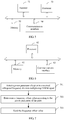
- FIG. 7 is a schematic flowchart of a frequency offset correction method according to an embodiment of the present invention.
- the method provided in this embodiment may be executed by a receiving device configured to receive an OFDM signal in an OFDM system.
- the OFDM system further includes a transmitter configured to send the OFDM signal.
- the method includes: 701. Detect a power parameter of a pilot in a received orthogonal frequency division multiplexing OFDM signal.
- the power parameter of the pilot includes a difference between power of a low frequency pilot and power of a high frequency pilot, and at least one of the power of the low frequency pilot or the power of the high frequency pilot, where a frequency of a subcarrier used to carry the low frequency pilot is lower than a frequency of a subcarrier used to carry the high frequency pilot.
- the OFDM signal received by the receiving device is collected, so as to obtain a sample signal; fast Fourier transformation is performed on the sample signal, so as to obtain the pilot in the OFDM signal; and the power parameter of the pilot is detected.
- the frequency offset value is used to indicate a degree and a direction that are of a difference that is between a center frequency of a laser configured to transmit the OFDM signal in the transmitter and a center frequency of a filter and that deviates from a first threshold
- the filter includes a multiplexer configured to filter the OFDM signal in the transmitter
- the first threshold is a difference between a center frequency of the filter and a center frequency of the laser when a bit error rate of the OFDM signal is lowest.
- the power parameter p of the pilot that is obtained by means of detection is compared with a second threshold Po, where the second threshold is a power parameter of the pilot that is detected when the difference between the center frequency of the filter and the center frequency of the laser is equal to the first threshold; and if the power parameter p of the pilot is greater than the second threshold Po, that the frequency offset value is +S is determined; or if the power parameter p of the pilot is less than the second threshold Po, that the frequency offset value is -S is determined; where S is a preset constant, a value range of S is a positive number, and S is a step at which the center frequency of the laser is shifted when the difference between the center frequency of the filter and the center frequency of the laser is equal to the first threshold in a manner in which the center frequency of the filter remains unchanged and the center frequency of the laser is shifted, so as to detect the second threshold Po.
- the second threshold is a power parameter of the pilot that is detected when the difference between the center frequency of the filter and the center frequency of the laser is
- the filter further includes the demultiplexer.
- the center frequency of the filter is an equivalent center frequency obtained by cascading the multiplexer and the demultiplexer, where the equivalent center frequency is a center frequency of an overlapping filtering window between a filtering window of the multiplexer and a filtering window of the demultiplexer.
- the frequency offset value is sent by using an auto-negotiation data packet, so that the transmitter corrects the difference between the center frequency of the laser and the center frequency of the filter according to the frequency offset value.
- a frequency offset value used to indicate a degree and a direction that are of a difference that is between a center frequency of a laser and a center frequency of a filter and that deviates from a first threshold is determined according to the power parameter of the pilot, and then the receiving device corrects the difference between the center frequency of the laser and the center frequency of the filter according to the determined frequency offset value, thereby implementing frequency offset correction of an OFDM system.
- frequency offset correction is performed according to the difference between the center frequency of the laser and the center frequency of the filter, which is not only applicable to frequency offset caused by offset of the center frequency of the laser, but also applicable to frequency offset caused by offset of the center frequency of the filter, efficiency of frequency offset correction is improved.
- FIG. 8 is a schematic flowchart of a frequency offset correction method according to another embodiment of the present invention.
- the method provided in this embodiment may be executed by a transmitter configured to send an OFDM signal in an OFDM system.
- the OFDM system further includes a receiving device configured to receive the OFDM signal, and the receiving device may be the receiving device in the foregoing embodiment.
- the frequency offset correction method includes: 801. Receive a frequency offset value.
- the frequency offset value is used to indicate a degree and a direction that are of a difference that is between a center frequency of a laser configured to transmit the OFDM signal in the transmitter and a center frequency of a filter and that deviates from a first threshold
- the filter includes a multiplexer configured to filter the OFDM signal in the transmitter
- the first threshold is a difference between a center frequency of the filter and a center frequency of the laser when a bit error rate of the OFDM signal is lowest.
- the filter further includes the demultiplexer.
- the center frequency of the filter is an equivalent center frequency obtained by cascading the multiplexer and the demultiplexer, where the equivalent center frequency is a center frequency of an overlapping filtering window between a filtering window of the multiplexer and a filtering window of the demultiplexer.
- the center frequency of the laser is adjusted towards a difference decreasing direction, where an adjustment amplitude is equal to an absolute value of the frequency offset value; or if the frequency offset value indicates that the difference between the center frequency of the laser and the center frequency of the filter deviates from the first threshold towards a difference decreasing direction, the center frequency of the laser is adjusted towards a difference increasing direction, where an adjustment amplitude is equal to an absolute value of the frequency offset value, so that the difference between the center frequency of the laser and the center frequency of the filter remains stable, and therefore a subcarrier at a fading point can be filtered out after the filter performs single sideband filtering.
- the method in this embodiment usually needs to be repeatedly executed for multiple times until frequency offset correction is completed, that is, the power parameter of the pilot in the OFDM signal received by the receiving device is within a preset range.
- a quantity of times of repeatedly executing the method in this embodiment should not be greater than a preset maximum quantity of execution times, and if a total quantity of times of repeatedly executing the method is greater than the maximum quantity of execution times, it indicates that an exception of an endless loop occurs.
- a frequency offset value used to indicate a degree and a direction that are of a difference that is between a center frequency of a laser and a center frequency of a filter and that deviates from a first threshold is determined according to the power parameter of the pilot, and then the receiving device corrects the difference between the center frequency of the laser and the center frequency of the filter according to the determined frequency offset value, thereby implementing frequency offset correction of an OFDM system.
- frequency offset correction is performed according to the difference between the center frequency of the laser and the center frequency of the filter, which is not only applicable to frequency offset caused by offset of the center frequency of the laser, but also applicable to frequency offset caused by offset of the center frequency of the filter, efficiency of frequency offset correction is improved.
- the program may be stored in a computer readable storage medium. When the program runs, the steps of the method embodiments are performed.
- the foregoing storage medium includes: any medium that can store program code, such as a ROM, a RAM, a magnetic disk, or an optical disc.
Landscapes
- Physics & Mathematics (AREA)
- Engineering & Computer Science (AREA)
- Computer Networks & Wireless Communication (AREA)
- Signal Processing (AREA)
- Electromagnetism (AREA)
- Optics & Photonics (AREA)
- Optical Communication System (AREA)
Claims (14)
- Empfangsvorrichtung (10), welche umfasst:ein Detektionsmodul (11), das dafür ausgelegt ist, einen Leistungsparameter eines Piloten in einem empfangenen orthogonalen Frequenzmultiplex- (Orthogonal Frequency Division Multiplexing, OFDM-) Signal zu detektieren;ein Bestimmungsmodul (12), das dafür ausgelegt ist, entsprechend dem Leistungsparameter des Piloten einen Frequenzversatzwert zu bestimmen, wobei der Frequenzversatzwert verwendet wird, um einen Grad und eine Richtung anzugeben, welche sich auf eine Differenz beziehen, welche zwischen einer Mittelfrequenz eines Filters und einer Mittelfrequenz eines Lasers, der dafür ausgelegt ist, das OFDM-Signal in einem Sender zu senden, vorhanden ist und welche von einem ersten Schwellenwert abweicht, das Filter einen Multiplexer umfasst, der dafür ausgelegt ist, das OFDM-Signal in dem Sender zu filtern, und der erste Schwellenwert eine Differenz zwischen einer Mittelfrequenz des Lasers und einer Mittelfrequenz des Filters ist, wenn eine Bitfehlerrate des OFDM-Signals am niedrigsten ist; undein Sendemodul (13), das dafür ausgelegt ist, den Frequenzversatzwert zu senden.
- Empfangsvorrichtung (10) nach Anspruch 1, wobei:
das Bestimmungsmodul (12) speziell dafür ausgelegt ist, eine Berechnung gemäß einer linearen Entsprechung zwischen dem vorbestimmten Leistungsparameter p des Piloten und dem Frequenzversatzwert y auszuführen, um so den Frequenzversatzwert y=kp+c zu erhalten, wobei k und c Konstanten sind, die durch Testen der linearen Entsprechung zwischen dem Leistungsparameter p des Piloten und dem Frequenzversatzwert y = (v1-v2) -Δ auf eine Weise erhalten werden, bei welcher die Mittelfrequenz v1 des Filters unverändert bleibt und die Mittelfrequenz v2 des Lasers verschoben wird, und Δ der erste Schwellenwert ist. - Empfangsvorrichtung (10) nach Anspruch 1, wobei das Bestimmungsmodul (12) umfasst:eine Vergleichseinheit (121), die dafür ausgelegt ist, den Leistungsparameter p des Piloten, welcher mittels Detektion erhalten wird, mit einem zweiten Schwellenwert Po zu vergleichen, wobei der zweite Schwellenwert ein Leistungsparameter des Piloten ist, welcher detektiert wird, wenn die Differenz zwischen der Mittelfrequenz des Filters und der Mittelfrequenz des Lasers gleich dem ersten Schwellenwert ist;eine erste Bestimmungseinheit (122), die dafür ausgelegt ist: falls der Leistungsparameter p des Piloten größer als der zweite Schwellenwert Po ist, zu bestimmen, dass der Frequenzversatzwert +S ist, wobei S eine vorgegebene Konstante ist, ein Wertebereich von S eine positive Zahl ist und S ein Schritt ist, um welchen die Mittelfrequenz des Lasers verschoben wird, wenn die Differenz zwischen der Mittelfrequenz des Filters und der Mittelfrequenz des Lasers gleich dem ersten Schwellenwert ist, auf eine Weise, bei welcher die Mittelfrequenz des Filters unverändert bleibt und die Mittelfrequenz des Lasers verschoben wird, um so den zweiten Schwellenwert P0 zu detektieren; undeine zweite Bestimmungseinheit (123), die dafür ausgelegt ist: falls der Leistungsparameter p des Piloten kleiner als der zweite Schwellenwert P0 ist, zu bestimmen, dass der Frequenzversatzwert -S ist, wobei S eine vorgegebene Konstante ist, ein Wertebereich von S eine positive Zahl ist und S ein Schritt ist, um welchen die Mittelfrequenz des Lasers verschoben wird, wenn die Differenz zwischen der Mittelfrequenz des Filters und der Mittelfrequenz des Lasers gleich dem ersten Schwellenwert ist, auf eine Weise, bei welcher die Mittelfrequenz des Filters unverändert bleibt und die Mittelfrequenz des Lasers verschoben wird, um so den zweiten Schwellenwert P0 zu detektieren.
- Empfangsvorrichtung (10) nach einem der Ansprüche 1 bis 3, wobei:
der Leistungsparameter des Piloten eine Differenz zwischen der Leistung eines niederfrequenten Piloten und der Leistung eines hochfrequenten Piloten sowie wenigstens eine von der Leistung des niederfrequenten Piloten und der Leistung des hochfrequenten Piloten umfasst, wobei eine Frequenz eines Unterträgers, der verwendet wird, um den niederfrequenten Piloten zu transportieren, niedriger als eine Frequenz eines Unterträgers ist, der verwendet wird, um den hochfrequenten Piloten zu transportieren. - Empfangsvorrichtung (10) nach einem der Ansprüche 1 bis 4, wobei das Filter ferner einen Demultiplexer umfasst, der dafür ausgelegt ist, das OFDM-Signal in der Empfangsvorrichtung zu filtern; und
die Mittelfrequenz des Filters eine äquivalente Mittelfrequenz ist, die durch Kaskadieren des Multiplexers und des Demultiplexers erhalten wird, wobei die äquivalente Mittelfrequenz eine Mittelfrequenz eines überlappenden Filterfensters zwischen einem Filterfenster des Multiplexers und einem Filterfenster des Demultiplexers ist. - Sender (30), welcher umfasst:ein Empfangsmodul (31), das dafür ausgelegt ist, einen Frequenzversatzwert zu empfangen, wobei der Frequenzversatzwert verwendet wird, um einen Grad und eine Richtung anzugeben, welche sich auf eine Differenz beziehen, welche zwischen einer Mittelfrequenz eines Filters und einer Mittelfrequenz eines Lasers, der dafür ausgelegt ist, ein OFDM-Signal in dem Sender zu senden, vorhanden ist und welche von einem ersten Schwellenwert abweicht, das Filter einen Multiplexer umfasst, der dafür ausgelegt ist, das OFDM-Signal in dem Sender zu filtern, und der erste Schwellenwert eine Differenz zwischen einer Mittelfrequenz des Lasers und einer Mittelfrequenz des Filters ist, wenn eine Bitfehlerrate des OFDM-Signals am niedrigsten ist; undein Korrekturmodul (32), das dafür ausgelegt ist, die Differenz zwischen der Mittelfrequenz des Lasers und der Mittelfrequenz des Filters entsprechend dem Frequenzversatzwert zu korrigieren.
- Sender (30) nach Anspruch 6, wobei das Korrekturmodul (32) umfasst:eine erste Korrektureinheit (321), die dafür ausgelegt ist: falls der Frequenzversatzwert anzeigt, dass die Differenz zwischen der Mittelfrequenz des Filters und der Mittelfrequenz des Lasers von dem ersten Schwellenwert in einer Richtung abweicht, in der sich die Differenz vergrößert, die Mittelfrequenz des Lasers in einer Richtung zu verstellen, in der sich die Differenz verringert, wobei eine Amplitude der Verstellung gleich einem absoluten Betrag des Frequenzversatzwertes ist; undeine zweite Korrektureinheit (322), die dafür ausgelegt ist: falls der Frequenzversatzwert anzeigt, dass die Differenz zwischen der Mittelfrequenz des Filters und der Mittelfrequenz des Lasers von dem ersten Schwellenwert in einer Richtung abweicht, in der sich die Differenz verringert, die Mittelfrequenz des Lasers in einer Richtung zu verstellen, in der sich die Differenz vergrößert, wobei eine Amplitude der Verstellung gleich einem absoluten Betrag des Frequenzversatzwertes ist.
- Sender (30) nach Anspruch 7, wobei der Frequenzversatzwert y = (v1-v2) -Δ ist, v1 die Mittelfrequenz des Filters ist, v2 die Mittelfrequenz des Lasers ist und Δ der erste Schwellenwert ist; und das Korrekturmodul (32) ferner umfasst:
eine Beurteilungseinheit (322), die dafür ausgelegt ist: wenn der Frequenzversatzwert -S ist, zu bestimmen, dass die Differenz (v1-v2) zwischen der Mittelfrequenz des Filters und der Mittelfrequenz des Lasers vom ersten Schwellenwert in der Richtung abweicht, in der sich die Differenz verringert; oder wenn der Frequenzversatzwert +S ist, zu bestimmen, dass die Differenz (v1-v2) zwischen der Mittelfrequenz des Filters und der Mittelfrequenz des Lasers vom ersten Schwellenwert in der Richtung abweicht, in der sich die Differenz vergrößert; wobei ein Wertebereich von S eine positive Zahl ist. - Sender (30) nach einem der Ansprüche 6 bis 8, wobei das Filter ferner einen Demultiplexer umfasst, der dafür ausgelegt ist, das OFDM-Signal in einer Empfangsvorrichtung zu filtern; und
die Mittelfrequenz des Filters eine äquivalente Mittelfrequenz ist, die durch Kaskadieren des Multiplexers und des Demultiplexers erhalten wird, wobei die äquivalente Mittelfrequenz eine Mittelfrequenz eines überlappenden Filterfensters zwischen einem Filterfenster des Multiplexers und einem Filterfenster des Demultiplexers ist. - Verfahren zur Korrektur eines Frequenzversatzes, welches umfasst:Detektieren (701) eines Leistungsparameters eines Piloten in einem empfangenen orthogonalen Frequenzmultiplex-, OFDM-, Signal;Bestimmen (702) eines Frequenzversatzwertes entsprechend dem Leistungsparameter des Piloten, wobei der Frequenzversatzwert verwendet wird, um einen Grad und eine Richtung anzugeben, welche sich auf eine Differenz beziehen, welche zwischen einer Mittelfrequenz eines Lasers, der dafür ausgelegt ist, das OFDM-Signal in einem Sender zu senden, und einer Mittelfrequenz eines Filters vorhanden ist und welche von einem ersten Schwellenwert abweicht, das Filter einen Multiplexer umfasst, der dafür ausgelegt ist, das OFDM-Signal in dem Sender zu filtern, und der erste Schwellenwert eine Differenz zwischen einer Mittelfrequenz des Filters und einer Mittelfrequenz des Lasers ist, wenn eine Bitfehlerrate des OFDM-Signals am niedrigsten ist; undSenden (703) des Frequenzversatzwertes.
- Verfahren zur Korrektur eines Frequenzversatzes nach Anspruch 10, wobei das Bestimmen eines Frequenzversatzwertes entsprechend dem Leistungsparameter des Piloten umfasst:Ausführen einer Berechnung gemäß einer linearen Entsprechung zwischen dem vorbestimmten Leistungsparameter p des Piloten und dem Frequenzversatzwert y, um so den Frequenzversatzwert y=kp+c zu erhalten, wobei k und c Konstanten sind, die durch Testen der linearen Entsprechung zwischen dem Leistungsparameter p des Piloten und dem Frequenzversatzwert y = (v1-v2) -Δ auf eine Weise erhalten werden, bei welcher die Mittelfrequenz v1 des Filters unverändert bleibt und die Mittelfrequenz v2 des Lasers verschoben wird, und Δ der erste Schwellenwert ist; oderdas Bestimmen eines Frequenzversatzwertes entsprechend dem Leistungsparameter des Piloten umfasst:
Vergleichen des Leistungsparameters p des Piloten, welcher mittels Detektion erhalten wird, mit einem zweiten Schwellenwert P0, wobei der zweite Schwellenwert ein Leistungsparameter des Piloten ist, welcher detektiert wird, wenn die Differenz zwischen der Mittelfrequenz des Filters und der Mittelfrequenz des Lasers gleich dem ersten Schwellenwert ist; und falls der Leistungsparameter p des Piloten größer als der zweite Schwellenwert P0 ist, Bestimmen, dass der Frequenzversatzwert +S ist; oder falls der Leistungsparameter p des Piloten kleiner als der zweite Schwellenwert P0 ist, Bestimmen, dass der Frequenzversatzwert -S ist; wobei S eine vorgegebene Konstante ist, ein Wertebereich von S eine positive Zahl ist und S ein Schritt ist, um welchen die Mittelfrequenz des Lasers verschoben wird, wenn die Differenz zwischen der Mittelfrequenz des Filters und der Mittelfrequenz des Lasers gleich dem ersten Schwellenwert ist, auf eine Weise, bei welcher die Mittelfrequenz des Filters unverändert bleibt und die Mittelfrequenz des Lasers verschoben wird, um so den zweiten Schwellenwert P0 zu detektieren. - Verfahren zur Korrektur eines Frequenzversatzes, welches umfasst:Empfangen (801) eines Frequenzversatzwertes, wobei der Frequenzversatzwert verwendet wird, um einen Grad und eine Richtung anzugeben, welche sich auf eine Differenz beziehen, welche zwischen einer Mittelfrequenz eines Lasers, der dafür ausgelegt ist, das OFDM-Signal in einem Sender zu senden, und einer Mittelfrequenz eines Filters vorhanden ist und welche von einem ersten Schwellenwert abweicht, das Filter einen Multiplexer umfasst, der dafür ausgelegt ist, das OFDM-Signal in dem Sender zu filtern, und der erste Schwellenwert eine Differenz zwischen einer Mittelfrequenz des Filters und einer Mittelfrequenz des Lasers ist, wenn eine Bitfehlerrate des OFDM-Signals am niedrigsten ist; undKorrigieren (802) der Differenz zwischen der Mittelfrequenz des Filters und der Mittelfrequenz des Lasers entsprechend dem Frequenzversatzwert.
- Verfahren zur Korrektur eines Frequenzversatzes nach Anspruch 12, wobei das Korrigieren der Differenz zwischen der Mittelfrequenz des Filters und der Mittelfrequenz des Lasers entsprechend dem Frequenzversatzwert umfasst:falls der Frequenzversatzwert anzeigt, dass die Differenz zwischen der Mittelfrequenz des Filters und der Mittelfrequenz des Lasers von dem ersten Schwellenwert in einer Richtung abweicht, in der sich die Differenz vergrößert, Verstellen der Mittelfrequenz des Lasers in einer Richtung, in der sich die Differenz verringert, wobei eine Amplitude der Verstellung gleich einem absoluten Betrag des Frequenzversatzwertes ist; oderfalls der Frequenzversatzwert anzeigt, dass die Differenz zwischen der Mittelfrequenz des Filters und der Mittelfrequenz des Lasers von dem ersten Schwellenwert in einer Richtung abweicht, in der sich die Differenz verringert, Verstellen der Mittelfrequenz des Lasers in einer Richtung, in der sich die Differenz vergrößert, wobei eine Amplitude der Verstellung gleich einem absoluten Betrag des Frequenzversatzwertes ist.
- Verfahren zur Korrektur eines Frequenzversatzes nach Anspruch 13, wobei der Frequenzversatzwert y = (v1-v2) -Δ ist, v1 die Mittelfrequenz des Filters ist, v2 die Mittelfrequenz des Lasers ist und Δ der erste Schwellenwert ist; und
vor dem Verstellen der Mittelfrequenz des Lasers in einer Richtung, in der sich die Differenz verringert, wobei eine Amplitude der Verstellung gleich einem absoluten Betrag des Frequenzversatzwertes ist, das Verfahren ferner umfasst:wenn der Frequenzversatzwert -S ist, Bestimmen, dass die Differenz (v1-v2) zwischen der Mittelfrequenz des Filters und der Mittelfrequenz des Lasers vom ersten Schwellenwert in der Richtung abweicht, in der sich die Differenz verringert, wobei ein Wertebereich von S eine positive Zahl ist; odervor dem Verstellen der Mittelfrequenz des Lasers in einer Richtung, in der sich die Differenz vergrößert, wobei eine Amplitude der Verstellung gleich einem absoluten Betrag des Frequenzversatzwertes ist, das Verfahren ferner umfasst:
wenn der Frequenzversatzwert +S ist, Bestimmen, dass die Differenz (v1-v2) zwischen der Mittelfrequenz des Filters und der Mittelfrequenz des Lasers vom ersten Schwellenwert in der Richtung abweicht, in der sich die Differenz vergrößert; wobei ein Wertebereich von S eine positive Zahl ist.
Applications Claiming Priority (1)
| Application Number | Priority Date | Filing Date | Title |
|---|---|---|---|
| PCT/CN2014/077430 WO2015172324A1 (zh) | 2014-05-14 | 2014-05-14 | 发送器、接收器和频偏校正方法 |
Publications (3)
| Publication Number | Publication Date |
|---|---|
| EP3136622A1 EP3136622A1 (de) | 2017-03-01 |
| EP3136622A4 EP3136622A4 (de) | 2017-05-10 |
| EP3136622B1 true EP3136622B1 (de) | 2018-08-22 |
Family
ID=54479147
Family Applications (1)
| Application Number | Title | Priority Date | Filing Date |
|---|---|---|---|
| EP14891841.0A Active EP3136622B1 (de) | 2014-05-14 | 2014-05-14 | Sender, empfänger und frequenzkorrekturverfahren |
Country Status (4)
| Country | Link |
|---|---|
| US (1) | US10164763B2 (de) |
| EP (1) | EP3136622B1 (de) |
| CN (1) | CN106464372B (de) |
| WO (1) | WO2015172324A1 (de) |
Families Citing this family (5)
| Publication number | Priority date | Publication date | Assignee | Title |
|---|---|---|---|---|
| US10574351B2 (en) * | 2017-10-23 | 2020-02-25 | Huawei Technologies Co., Ltd. | Monitoring performance of optical network equipment using pilot tones |
| KR102348617B1 (ko) * | 2017-11-30 | 2022-01-06 | 가부시키가이샤 무라타 세이사쿠쇼 | 무선 통신 장치 |
| US10673528B1 (en) * | 2019-02-25 | 2020-06-02 | Huawei Technologies Co., Ltd. | Methods and apparatuses for controlling optical signals in optical networks |
| CN114422314B (zh) * | 2021-12-22 | 2024-05-24 | 江苏科大亨芯半导体技术有限公司 | 多载波鉴频方法及系统 |
| CN114244355B (zh) * | 2021-12-22 | 2025-10-03 | 海能达通信股份有限公司 | 一种频率校准方法、装置及电子设备 |
Family Cites Families (5)
| Publication number | Priority date | Publication date | Assignee | Title |
|---|---|---|---|---|
| US8050345B1 (en) * | 1999-08-09 | 2011-11-01 | Kamilo Feher | QAM and GMSK systems |
| US7061944B2 (en) * | 2001-05-25 | 2006-06-13 | International Business Machines Corporation | Apparatus and method for wavelength-locked loops for systems and applications employing electromagnetic signals |
| CN101154990B (zh) * | 2006-09-28 | 2011-09-21 | 中国科学院上海微系统与信息技术研究所 | 大功率发射台主导下的多个小功率发射台的同步方法 |
| US9036723B2 (en) * | 2012-09-20 | 2015-05-19 | Nec Laboratories America, Inc. | Full-range pilot-assisted frequency offset estimation for OFDM communication systems |
| CN103457902B (zh) * | 2013-09-13 | 2016-06-01 | 北京邮电大学 | 一种wdm-pon有线/无线可选择接入系统和方法 |
-
2014
- 2014-05-14 EP EP14891841.0A patent/EP3136622B1/de active Active
- 2014-05-14 CN CN201480078870.9A patent/CN106464372B/zh active Active
- 2014-05-14 WO PCT/CN2014/077430 patent/WO2015172324A1/zh not_active Ceased
-
2016
- 2016-11-14 US US15/351,131 patent/US10164763B2/en active Active
Non-Patent Citations (1)
| Title |
|---|
| None * |
Also Published As
| Publication number | Publication date |
|---|---|
| EP3136622A4 (de) | 2017-05-10 |
| WO2015172324A1 (zh) | 2015-11-19 |
| US10164763B2 (en) | 2018-12-25 |
| EP3136622A1 (de) | 2017-03-01 |
| CN106464372B (zh) | 2019-05-24 |
| US20170063519A1 (en) | 2017-03-02 |
| CN106464372A (zh) | 2017-02-22 |
Similar Documents
| Publication | Publication Date | Title |
|---|---|---|
| US8989602B2 (en) | Digital coherent optical receiver, adaptive equalizer, and digital coherent optical communication method | |
| EP3136622B1 (de) | Sender, empfänger und frequenzkorrekturverfahren | |
| US9692548B2 (en) | Techniques for blind equalization of high-order quadrature amplitude modulation signals | |
| EP2709327B1 (de) | Aktualisierungsvorrichtung und Verfahren für einen Verzerrerkoeffizienten, Empfänger und optisches Kommunikationssystem | |
| US9729362B1 (en) | Systems and methods for autonomous signal modulation format identification | |
| JP6236894B2 (ja) | 光位相補償装置、光受信器、ネットワークマネジメントシステム、および光位相補償方法 | |
| US11283528B2 (en) | Digital coherent receiver and digital coherent receiving method | |
| US9037004B2 (en) | Optical receiver, polarization separation device and polarization separating method | |
| US20130084080A1 (en) | Coherent optical receiver and coherent optical receiving method | |
| US20200052795A1 (en) | Digital coherent receiver and skew adjustment method thereof | |
| US10623128B2 (en) | Apparatus and method for processing a frequency offset of a pilot and receiver | |
| Torres et al. | Mitigation of time-varying distortions in Nyquist-WDM systems using machine learning | |
| Zhao et al. | A modulation format identification method based on amplitude deviation analysis of received optical communication signal | |
| RU2642482C1 (ru) | Способ настройки автоматической адаптивной компенсации дисперсии | |
| US20190149231A1 (en) | Apparatus and method for monitoring optical signal to noise ratio, receiver and communication system | |
| US20170041080A1 (en) | Optical receiver and signal processing method | |
| US11303381B2 (en) | Processing parameter and resource sharing architecture for superchannel based transmission systems | |
| US9906310B2 (en) | Signal receiving method and receiver | |
| Olmedo et al. | Carrier recovery techniques for semiconductor laser frequency noise for 28 Gbd DP-16QAM | |
| JP6834328B2 (ja) | 送信側変調器のバイアスドリフトの推定装置、補償装置及び受信機 | |
| JP5206867B2 (ja) | 光通信装置及び分散補償方法 | |
| Zibar et al. | Joint iterative carrier synchronization and signal detection employing expectation maximization | |
| US20180175933A1 (en) | Communication device, communication system and communication method for transmitting optical signal | |
| US20170294971A1 (en) | Apparatus and Method for Blind LOFO Estimation in Coherent Optical Receiver | |
| JP6025918B1 (ja) | 光受信装置及びコヒーレント光通信システム |
Legal Events
| Date | Code | Title | Description |
|---|---|---|---|
| STAA | Information on the status of an ep patent application or granted ep patent |
Free format text: STATUS: THE INTERNATIONAL PUBLICATION HAS BEEN MADE |
|
| PUAI | Public reference made under article 153(3) epc to a published international application that has entered the european phase |
Free format text: ORIGINAL CODE: 0009012 |
|
| STAA | Information on the status of an ep patent application or granted ep patent |
Free format text: STATUS: REQUEST FOR EXAMINATION WAS MADE |
|
| 17P | Request for examination filed |
Effective date: 20161125 |
|
| AK | Designated contracting states |
Kind code of ref document: A1 Designated state(s): AL AT BE BG CH CY CZ DE DK EE ES FI FR GB GR HR HU IE IS IT LI LT LU LV MC MK MT NL NO PL PT RO RS SE SI SK SM TR |
|
| AX | Request for extension of the european patent |
Extension state: BA ME |
|
| A4 | Supplementary search report drawn up and despatched |
Effective date: 20170406 |
|
| RIC1 | Information provided on ipc code assigned before grant |
Ipc: H04B 10/548 20130101ALI20170401BHEP Ipc: H04B 10/50 20130101ALI20170401BHEP Ipc: H04L 7/00 20060101ALI20170401BHEP Ipc: H04B 10/2507 20130101AFI20170401BHEP |
|
| DAX | Request for extension of the european patent (deleted) | ||
| GRAP | Despatch of communication of intention to grant a patent |
Free format text: ORIGINAL CODE: EPIDOSNIGR1 |
|
| STAA | Information on the status of an ep patent application or granted ep patent |
Free format text: STATUS: GRANT OF PATENT IS INTENDED |
|
| INTG | Intention to grant announced |
Effective date: 20180302 |
|
| GRAS | Grant fee paid |
Free format text: ORIGINAL CODE: EPIDOSNIGR3 |
|
| GRAA | (expected) grant |
Free format text: ORIGINAL CODE: 0009210 |
|
| STAA | Information on the status of an ep patent application or granted ep patent |
Free format text: STATUS: THE PATENT HAS BEEN GRANTED |
|
| AK | Designated contracting states |
Kind code of ref document: B1 Designated state(s): AL AT BE BG CH CY CZ DE DK EE ES FI FR GB GR HR HU IE IS IT LI LT LU LV MC MK MT NL NO PL PT RO RS SE SI SK SM TR |
|
| REG | Reference to a national code |
Ref country code: GB Ref legal event code: FG4D |
|
| REG | Reference to a national code |
Ref country code: CH Ref legal event code: EP |
|
| REG | Reference to a national code |
Ref country code: AT Ref legal event code: REF Ref document number: 1033689 Country of ref document: AT Kind code of ref document: T Effective date: 20180915 |
|
| REG | Reference to a national code |
Ref country code: IE Ref legal event code: FG4D |
|
| REG | Reference to a national code |
Ref country code: DE Ref legal event code: R096 Ref document number: 602014031150 Country of ref document: DE |
|
| REG | Reference to a national code |
Ref country code: NL Ref legal event code: MP Effective date: 20180822 |
|
| REG | Reference to a national code |
Ref country code: LT Ref legal event code: MG4D |
|
| PG25 | Lapsed in a contracting state [announced via postgrant information from national office to epo] |
Ref country code: RS Free format text: LAPSE BECAUSE OF FAILURE TO SUBMIT A TRANSLATION OF THE DESCRIPTION OR TO PAY THE FEE WITHIN THE PRESCRIBED TIME-LIMIT Effective date: 20180822 Ref country code: IS Free format text: LAPSE BECAUSE OF FAILURE TO SUBMIT A TRANSLATION OF THE DESCRIPTION OR TO PAY THE FEE WITHIN THE PRESCRIBED TIME-LIMIT Effective date: 20181222 Ref country code: LT Free format text: LAPSE BECAUSE OF FAILURE TO SUBMIT A TRANSLATION OF THE DESCRIPTION OR TO PAY THE FEE WITHIN THE PRESCRIBED TIME-LIMIT Effective date: 20180822 Ref country code: BG Free format text: LAPSE BECAUSE OF FAILURE TO SUBMIT A TRANSLATION OF THE DESCRIPTION OR TO PAY THE FEE WITHIN THE PRESCRIBED TIME-LIMIT Effective date: 20181122 Ref country code: SE Free format text: LAPSE BECAUSE OF FAILURE TO SUBMIT A TRANSLATION OF THE DESCRIPTION OR TO PAY THE FEE WITHIN THE PRESCRIBED TIME-LIMIT Effective date: 20180822 Ref country code: NL Free format text: LAPSE BECAUSE OF FAILURE TO SUBMIT A TRANSLATION OF THE DESCRIPTION OR TO PAY THE FEE WITHIN THE PRESCRIBED TIME-LIMIT Effective date: 20180822 Ref country code: FI Free format text: LAPSE BECAUSE OF FAILURE TO SUBMIT A TRANSLATION OF THE DESCRIPTION OR TO PAY THE FEE WITHIN THE PRESCRIBED TIME-LIMIT Effective date: 20180822 Ref country code: GR Free format text: LAPSE BECAUSE OF FAILURE TO SUBMIT A TRANSLATION OF THE DESCRIPTION OR TO PAY THE FEE WITHIN THE PRESCRIBED TIME-LIMIT Effective date: 20181123 Ref country code: NO Free format text: LAPSE BECAUSE OF FAILURE TO SUBMIT A TRANSLATION OF THE DESCRIPTION OR TO PAY THE FEE WITHIN THE PRESCRIBED TIME-LIMIT Effective date: 20181122 |
|
| REG | Reference to a national code |
Ref country code: AT Ref legal event code: MK05 Ref document number: 1033689 Country of ref document: AT Kind code of ref document: T Effective date: 20180822 |
|
| PG25 | Lapsed in a contracting state [announced via postgrant information from national office to epo] |
Ref country code: LV Free format text: LAPSE BECAUSE OF FAILURE TO SUBMIT A TRANSLATION OF THE DESCRIPTION OR TO PAY THE FEE WITHIN THE PRESCRIBED TIME-LIMIT Effective date: 20180822 Ref country code: HR Free format text: LAPSE BECAUSE OF FAILURE TO SUBMIT A TRANSLATION OF THE DESCRIPTION OR TO PAY THE FEE WITHIN THE PRESCRIBED TIME-LIMIT Effective date: 20180822 Ref country code: AL Free format text: LAPSE BECAUSE OF FAILURE TO SUBMIT A TRANSLATION OF THE DESCRIPTION OR TO PAY THE FEE WITHIN THE PRESCRIBED TIME-LIMIT Effective date: 20180822 |
|
| PG25 | Lapsed in a contracting state [announced via postgrant information from national office to epo] |
Ref country code: RO Free format text: LAPSE BECAUSE OF FAILURE TO SUBMIT A TRANSLATION OF THE DESCRIPTION OR TO PAY THE FEE WITHIN THE PRESCRIBED TIME-LIMIT Effective date: 20180822 Ref country code: IT Free format text: LAPSE BECAUSE OF FAILURE TO SUBMIT A TRANSLATION OF THE DESCRIPTION OR TO PAY THE FEE WITHIN THE PRESCRIBED TIME-LIMIT Effective date: 20180822 Ref country code: CZ Free format text: LAPSE BECAUSE OF FAILURE TO SUBMIT A TRANSLATION OF THE DESCRIPTION OR TO PAY THE FEE WITHIN THE PRESCRIBED TIME-LIMIT Effective date: 20180822 Ref country code: PL Free format text: LAPSE BECAUSE OF FAILURE TO SUBMIT A TRANSLATION OF THE DESCRIPTION OR TO PAY THE FEE WITHIN THE PRESCRIBED TIME-LIMIT Effective date: 20180822 Ref country code: ES Free format text: LAPSE BECAUSE OF FAILURE TO SUBMIT A TRANSLATION OF THE DESCRIPTION OR TO PAY THE FEE WITHIN THE PRESCRIBED TIME-LIMIT Effective date: 20180822 Ref country code: AT Free format text: LAPSE BECAUSE OF FAILURE TO SUBMIT A TRANSLATION OF THE DESCRIPTION OR TO PAY THE FEE WITHIN THE PRESCRIBED TIME-LIMIT Effective date: 20180822 Ref country code: EE Free format text: LAPSE BECAUSE OF FAILURE TO SUBMIT A TRANSLATION OF THE DESCRIPTION OR TO PAY THE FEE WITHIN THE PRESCRIBED TIME-LIMIT Effective date: 20180822 |
|
| REG | Reference to a national code |
Ref country code: DE Ref legal event code: R097 Ref document number: 602014031150 Country of ref document: DE |
|
| PG25 | Lapsed in a contracting state [announced via postgrant information from national office to epo] |
Ref country code: DK Free format text: LAPSE BECAUSE OF FAILURE TO SUBMIT A TRANSLATION OF THE DESCRIPTION OR TO PAY THE FEE WITHIN THE PRESCRIBED TIME-LIMIT Effective date: 20180822 Ref country code: SM Free format text: LAPSE BECAUSE OF FAILURE TO SUBMIT A TRANSLATION OF THE DESCRIPTION OR TO PAY THE FEE WITHIN THE PRESCRIBED TIME-LIMIT Effective date: 20180822 Ref country code: SK Free format text: LAPSE BECAUSE OF FAILURE TO SUBMIT A TRANSLATION OF THE DESCRIPTION OR TO PAY THE FEE WITHIN THE PRESCRIBED TIME-LIMIT Effective date: 20180822 |
|
| PLBE | No opposition filed within time limit |
Free format text: ORIGINAL CODE: 0009261 |
|
| STAA | Information on the status of an ep patent application or granted ep patent |
Free format text: STATUS: NO OPPOSITION FILED WITHIN TIME LIMIT |
|
| 26N | No opposition filed |
Effective date: 20190523 |
|
| PG25 | Lapsed in a contracting state [announced via postgrant information from national office to epo] |
Ref country code: SI Free format text: LAPSE BECAUSE OF FAILURE TO SUBMIT A TRANSLATION OF THE DESCRIPTION OR TO PAY THE FEE WITHIN THE PRESCRIBED TIME-LIMIT Effective date: 20180822 |
|
| REG | Reference to a national code |
Ref country code: CH Ref legal event code: PL |
|
| PG25 | Lapsed in a contracting state [announced via postgrant information from national office to epo] |
Ref country code: LI Free format text: LAPSE BECAUSE OF NON-PAYMENT OF DUE FEES Effective date: 20190531 Ref country code: CH Free format text: LAPSE BECAUSE OF NON-PAYMENT OF DUE FEES Effective date: 20190531 Ref country code: MC Free format text: LAPSE BECAUSE OF FAILURE TO SUBMIT A TRANSLATION OF THE DESCRIPTION OR TO PAY THE FEE WITHIN THE PRESCRIBED TIME-LIMIT Effective date: 20180822 |
|
| REG | Reference to a national code |
Ref country code: BE Ref legal event code: MM Effective date: 20190531 |
|
| PG25 | Lapsed in a contracting state [announced via postgrant information from national office to epo] |
Ref country code: LU Free format text: LAPSE BECAUSE OF NON-PAYMENT OF DUE FEES Effective date: 20190514 |
|
| PG25 | Lapsed in a contracting state [announced via postgrant information from national office to epo] |
Ref country code: TR Free format text: LAPSE BECAUSE OF FAILURE TO SUBMIT A TRANSLATION OF THE DESCRIPTION OR TO PAY THE FEE WITHIN THE PRESCRIBED TIME-LIMIT Effective date: 20180822 |
|
| PG25 | Lapsed in a contracting state [announced via postgrant information from national office to epo] |
Ref country code: IE Free format text: LAPSE BECAUSE OF NON-PAYMENT OF DUE FEES Effective date: 20190514 |
|
| PG25 | Lapsed in a contracting state [announced via postgrant information from national office to epo] |
Ref country code: BE Free format text: LAPSE BECAUSE OF NON-PAYMENT OF DUE FEES Effective date: 20190531 |
|
| PG25 | Lapsed in a contracting state [announced via postgrant information from national office to epo] |
Ref country code: PT Free format text: LAPSE BECAUSE OF FAILURE TO SUBMIT A TRANSLATION OF THE DESCRIPTION OR TO PAY THE FEE WITHIN THE PRESCRIBED TIME-LIMIT Effective date: 20181222 Ref country code: FR Free format text: LAPSE BECAUSE OF NON-PAYMENT OF DUE FEES Effective date: 20190531 |
|
| PG25 | Lapsed in a contracting state [announced via postgrant information from national office to epo] |
Ref country code: CY Free format text: LAPSE BECAUSE OF FAILURE TO SUBMIT A TRANSLATION OF THE DESCRIPTION OR TO PAY THE FEE WITHIN THE PRESCRIBED TIME-LIMIT Effective date: 20180822 |
|
| PG25 | Lapsed in a contracting state [announced via postgrant information from national office to epo] |
Ref country code: MT Free format text: LAPSE BECAUSE OF FAILURE TO SUBMIT A TRANSLATION OF THE DESCRIPTION OR TO PAY THE FEE WITHIN THE PRESCRIBED TIME-LIMIT Effective date: 20180822 Ref country code: HU Free format text: LAPSE BECAUSE OF FAILURE TO SUBMIT A TRANSLATION OF THE DESCRIPTION OR TO PAY THE FEE WITHIN THE PRESCRIBED TIME-LIMIT; INVALID AB INITIO Effective date: 20140514 |
|
| PG25 | Lapsed in a contracting state [announced via postgrant information from national office to epo] |
Ref country code: MK Free format text: LAPSE BECAUSE OF FAILURE TO SUBMIT A TRANSLATION OF THE DESCRIPTION OR TO PAY THE FEE WITHIN THE PRESCRIBED TIME-LIMIT Effective date: 20180822 |
|
| PGFP | Annual fee paid to national office [announced via postgrant information from national office to epo] |
Ref country code: DE Payment date: 20250402 Year of fee payment: 12 |
|
| PGFP | Annual fee paid to national office [announced via postgrant information from national office to epo] |
Ref country code: GB Payment date: 20250401 Year of fee payment: 12 |