EP3136539A1 - Method and device for the charging of batteries - Google Patents
Method and device for the charging of batteries Download PDFInfo
- Publication number
- EP3136539A1 EP3136539A1 EP16190154.1A EP16190154A EP3136539A1 EP 3136539 A1 EP3136539 A1 EP 3136539A1 EP 16190154 A EP16190154 A EP 16190154A EP 3136539 A1 EP3136539 A1 EP 3136539A1
- Authority
- EP
- European Patent Office
- Prior art keywords
- charging
- battery
- voltage
- current
- charge
- Prior art date
- Legal status (The legal status is an assumption and is not a legal conclusion. Google has not performed a legal analysis and makes no representation as to the accuracy of the status listed.)
- Withdrawn
Links
- 238000007600 charging Methods 0.000 title claims abstract description 321
- 238000000034 method Methods 0.000 title claims abstract description 77
- 230000008569 process Effects 0.000 claims abstract description 30
- 239000002253 acid Substances 0.000 claims abstract description 12
- 230000001105 regulatory effect Effects 0.000 claims abstract description 5
- 230000028161 membrane depolarization Effects 0.000 claims description 16
- 230000001276 controlling effect Effects 0.000 claims description 3
- 230000003111 delayed effect Effects 0.000 claims description 2
- 230000006978 adaptation Effects 0.000 claims 1
- 238000010438 heat treatment Methods 0.000 description 9
- 230000032683 aging Effects 0.000 description 5
- 230000008901 benefit Effects 0.000 description 5
- 230000033228 biological regulation Effects 0.000 description 4
- 238000010586 diagram Methods 0.000 description 4
- 230000005611 electricity Effects 0.000 description 3
- 238000006243 chemical reaction Methods 0.000 description 2
- 230000007423 decrease Effects 0.000 description 2
- 230000009467 reduction Effects 0.000 description 2
- 230000004044 response Effects 0.000 description 2
- 238000010998 test method Methods 0.000 description 2
- WHXSMMKQMYFTQS-UHFFFAOYSA-N Lithium Chemical compound [Li] WHXSMMKQMYFTQS-UHFFFAOYSA-N 0.000 description 1
- 238000001311 chemical methods and process Methods 0.000 description 1
- 238000010277 constant-current charging Methods 0.000 description 1
- 238000005260 corrosion Methods 0.000 description 1
- 230000007797 corrosion Effects 0.000 description 1
- 238000005516 engineering process Methods 0.000 description 1
- 238000002847 impedance measurement Methods 0.000 description 1
- 230000000977 initiatory effect Effects 0.000 description 1
- 229910052744 lithium Inorganic materials 0.000 description 1
- 229910052987 metal hydride Inorganic materials 0.000 description 1
- 238000004904 shortening Methods 0.000 description 1
- XLYOFNOQVPJJNP-UHFFFAOYSA-N water Substances O XLYOFNOQVPJJNP-UHFFFAOYSA-N 0.000 description 1
Images


Classifications
-
- H—ELECTRICITY
- H01—ELECTRIC ELEMENTS
- H01M—PROCESSES OR MEANS, e.g. BATTERIES, FOR THE DIRECT CONVERSION OF CHEMICAL ENERGY INTO ELECTRICAL ENERGY
- H01M10/00—Secondary cells; Manufacture thereof
- H01M10/06—Lead-acid accumulators
-
- H02J7/045—
-
- G—PHYSICS
- G01—MEASURING; TESTING
- G01R—MEASURING ELECTRIC VARIABLES; MEASURING MAGNETIC VARIABLES
- G01R31/00—Arrangements for testing electric properties; Arrangements for locating electric faults; Arrangements for electrical testing characterised by what is being tested not provided for elsewhere
- G01R31/36—Arrangements for testing, measuring or monitoring the electrical condition of accumulators or electric batteries, e.g. capacity or state of charge [SoC]
- G01R31/382—Arrangements for monitoring battery or accumulator variables, e.g. SoC
- G01R31/3835—Arrangements for monitoring battery or accumulator variables, e.g. SoC involving only voltage measurements
-
- G—PHYSICS
- G01—MEASURING; TESTING
- G01R—MEASURING ELECTRIC VARIABLES; MEASURING MAGNETIC VARIABLES
- G01R31/00—Arrangements for testing electric properties; Arrangements for locating electric faults; Arrangements for electrical testing characterised by what is being tested not provided for elsewhere
- G01R31/36—Arrangements for testing, measuring or monitoring the electrical condition of accumulators or electric batteries, e.g. capacity or state of charge [SoC]
- G01R31/385—Arrangements for measuring battery or accumulator variables
- G01R31/387—Determining ampere-hour charge capacity or SoC
- G01R31/388—Determining ampere-hour charge capacity or SoC involving voltage measurements
-
- H—ELECTRICITY
- H01—ELECTRIC ELEMENTS
- H01M—PROCESSES OR MEANS, e.g. BATTERIES, FOR THE DIRECT CONVERSION OF CHEMICAL ENERGY INTO ELECTRICAL ENERGY
- H01M10/00—Secondary cells; Manufacture thereof
- H01M10/42—Methods or arrangements for servicing or maintenance of secondary cells or secondary half-cells
- H01M10/44—Methods for charging or discharging
- H01M10/446—Initial charging measures
-
- H—ELECTRICITY
- H02—GENERATION; CONVERSION OR DISTRIBUTION OF ELECTRIC POWER
- H02J—CIRCUIT ARRANGEMENTS OR SYSTEMS FOR SUPPLYING OR DISTRIBUTING ELECTRIC POWER; SYSTEMS FOR STORING ELECTRIC ENERGY
- H02J7/00—Circuit arrangements for charging or depolarising batteries or for supplying loads from batteries
- H02J7/007—Regulation of charging or discharging current or voltage
- H02J7/0071—Regulation of charging or discharging current or voltage with a programmable schedule
-
- H—ELECTRICITY
- H02—GENERATION; CONVERSION OR DISTRIBUTION OF ELECTRIC POWER
- H02J—CIRCUIT ARRANGEMENTS OR SYSTEMS FOR SUPPLYING OR DISTRIBUTING ELECTRIC POWER; SYSTEMS FOR STORING ELECTRIC ENERGY
- H02J7/00—Circuit arrangements for charging or depolarising batteries or for supplying loads from batteries
- H02J7/007—Regulation of charging or discharging current or voltage
- H02J7/00712—Regulation of charging or discharging current or voltage the cycle being controlled or terminated in response to electric parameters
- H02J7/007182—Regulation of charging or discharging current or voltage the cycle being controlled or terminated in response to electric parameters in response to battery voltage
-
- H02J7/0086—
-
- H—ELECTRICITY
- H02—GENERATION; CONVERSION OR DISTRIBUTION OF ELECTRIC POWER
- H02J—CIRCUIT ARRANGEMENTS OR SYSTEMS FOR SUPPLYING OR DISTRIBUTING ELECTRIC POWER; SYSTEMS FOR STORING ELECTRIC ENERGY
- H02J7/00—Circuit arrangements for charging or depolarising batteries or for supplying loads from batteries
- H02J7/02—Circuit arrangements for charging or depolarising batteries or for supplying loads from batteries for charging batteries from ac mains by converters
- H02J7/04—Regulation of charging current or voltage
-
- H—ELECTRICITY
- H02—GENERATION; CONVERSION OR DISTRIBUTION OF ELECTRIC POWER
- H02J—CIRCUIT ARRANGEMENTS OR SYSTEMS FOR SUPPLYING OR DISTRIBUTING ELECTRIC POWER; SYSTEMS FOR STORING ELECTRIC ENERGY
- H02J7/00—Circuit arrangements for charging or depolarising batteries or for supplying loads from batteries
- H02J7/007—Regulation of charging or discharging current or voltage
- H02J7/00711—Regulation of charging or discharging current or voltage with introduction of pulses during the charging process
-
- Y—GENERAL TAGGING OF NEW TECHNOLOGICAL DEVELOPMENTS; GENERAL TAGGING OF CROSS-SECTIONAL TECHNOLOGIES SPANNING OVER SEVERAL SECTIONS OF THE IPC; TECHNICAL SUBJECTS COVERED BY FORMER USPC CROSS-REFERENCE ART COLLECTIONS [XRACs] AND DIGESTS
- Y02—TECHNOLOGIES OR APPLICATIONS FOR MITIGATION OR ADAPTATION AGAINST CLIMATE CHANGE
- Y02E—REDUCTION OF GREENHOUSE GAS [GHG] EMISSIONS, RELATED TO ENERGY GENERATION, TRANSMISSION OR DISTRIBUTION
- Y02E60/00—Enabling technologies; Technologies with a potential or indirect contribution to GHG emissions mitigation
- Y02E60/10—Energy storage using batteries
-
- Y—GENERAL TAGGING OF NEW TECHNOLOGICAL DEVELOPMENTS; GENERAL TAGGING OF CROSS-SECTIONAL TECHNOLOGIES SPANNING OVER SEVERAL SECTIONS OF THE IPC; TECHNICAL SUBJECTS COVERED BY FORMER USPC CROSS-REFERENCE ART COLLECTIONS [XRACs] AND DIGESTS
- Y02—TECHNOLOGIES OR APPLICATIONS FOR MITIGATION OR ADAPTATION AGAINST CLIMATE CHANGE
- Y02T—CLIMATE CHANGE MITIGATION TECHNOLOGIES RELATED TO TRANSPORTATION
- Y02T10/00—Road transport of goods or passengers
- Y02T10/60—Other road transportation technologies with climate change mitigation effect
- Y02T10/70—Energy storage systems for electromobility, e.g. batteries
Abstract
Die Erfindung betrifft ein Verfahren und eine Vorrichtung zum Laden von Batterien, insbesondere Bleisäurebatterien, mit einer vorgegebenen Ladeschlussspannung (U LS ), wobei vor dem Ladevorgang der Ladezustand der Batterie (10) festgestellt wird, und die Batterie (10) während des Ladevorgangs mit einem Ladestrom (I L ) oder einer Ladespannung (U L ) beaufschlagt wird. Zur Erzielung einer möglichst effizienten und schonenden Ladung der Batterie (10) und Erhöhung der Lebensdauer der Batterie (10) ist vorgesehen, dass die Ladespannung (U L ) während einer vorgegebenen Ladezeit (t' Laden ) durch eingeprägte Strompulse oder Spannungspulse zwischen einer Ladestartspannung (U LA ) gemäß dem Ladezustand der Batterie (10) und der Ladeschlussspannung (U LS ) schrittweise erhöht wird und in den Pausen zwischen zwei Strompulsen oder Spannungspulsen der Innenwiderstand (R I ) der Batterie (10) gemessen wird, und der Ladestrom (I L ) oder die Ladespannung (U L ) so geregelt wird, dass der Ladestrom (I L ) oder die Ladespannung (U L ) an den gemessenen Innenwiderstand (R I ) angepasst wird.The invention relates to a method and a device for charging batteries, in particular lead acid batteries, with a predetermined charge end voltage (U LS), wherein prior to charging the state of charge of the battery (10) is detected, and the battery (10) during the charging process with a Charging current (IL) or a charging voltage (UL) is applied. To achieve the most efficient and gentle charge of the battery (10) and increase the life of the battery (10) is provided that the charging voltage (UL) during a predetermined charging time (t 'charging) by impressed current pulses or voltage pulses between a charge start voltage (U LA) is incrementally increased in accordance with the state of charge of the battery (10) and the end-of-charge voltage (U LS) and the internal resistance (RI) of the battery (10) is measured during the pauses between two current pulses or voltage pulses, and the charging current (IL) or Charging voltage (UL) is regulated so that the charging current (IL) or the charging voltage (UL) is adjusted to the measured internal resistance (RI).
Description
Die Erfindung betrifft ein Verfahren und eine Vorrichtung zum Laden von Batterien, insbesondere Blei-Säure-Batterien, mit einer vorgegebenen Ladeschlussspannung, wobei vor dem Ladevorgang der Ladezustand der Batterie festgestellt wird, und die Batterie während des Ladevorgangs mit einem Ladestrom oder einer Ladespannung beaufschlagt wird.The invention relates to a method and a device for charging batteries, in particular lead-acid batteries, with a predetermined charge end voltage, wherein prior to charging the state of charge of the battery is detected, and the battery is charged during the charging process with a charging current or a charging voltage ,
Prinzipiell ist die gegenständliche Erfindung für das Laden verschiedenster aufladbarer Batterien bzw. Akkumulatoren, beispielsweise Blei-Säure-Batterien, Lithiumbatterien, Nickel-Metallhydrid (NiMH)-Batterien und viele mehr, geeignet. Bei Blei-Säure-Batterien, wie sie beispielsweise für elektrisch angetriebene Fahrzeuge eingesetzt werden, ist das erfindungsgemäße Ladeverfahren und die erfindungsgemäße Ladevorrichtung wegen der hohen Abhängigkeit des Innenwiderstands derartiger Batterien vom Ladezustand, jedoch besonders vorteilhaft.In principle, the subject invention is suitable for charging a variety of rechargeable batteries, such as lead-acid batteries, lithium batteries, nickel-metal hydride (NiMH) batteries and many more. In lead-acid batteries, as used for example for electrically driven vehicles, the charging method according to the invention and the charging device according to the invention is because of the high dependence of the internal resistance of such batteries from the state of charge, however, particularly advantageous.
Bei elektrisch betriebenen Fahrzeugen oder Transportmitteln, wie zum Beispiel sogenannten Flurförderzeugen (Stapler, Hubwagen, etc.), die häufig im Schichtbetrieb eingesetzt werden, ist eine regelmäßige Ladung der Batterien zwischen den Betriebs- oder Schichtzeiten erforderlich. Üblicherweise erfolgt die Ladung der Batterien unabhängig von deren Ladezustand. Der Innenwiderstand von Batterien, insbesondere jener von Blei-Säure-Batterien, weist aufgrund der chemischen Vorgänge in den Zellen der Batterie eine starke Abhängigkeit vom jeweiligen Ladezustand auf. Insbesondere ist der Innenwiderstand bei geringer Ladung der Batterie höher, weist bei einem mittleren Ladezustand ein Minimum auf und steigt dann in Abhängigkeit des Ladezustands wieder an. Darüber hinaus ist der Innenwiderstand von Batterien auch stark abhängig von der Betriebstemperatur und vom Alter der Batterie.In electrically operated vehicles or means of transport, such as so-called industrial trucks (stackers, pallet trucks, etc.), which are often used in stratified operation, a regular charge of the batteries between the operating or shift times is required. Usually, the batteries are charged regardless of their state of charge. The internal resistance of batteries, especially those of lead-acid batteries, has a strong dependence on the respective state of charge due to the chemical processes in the cells of the battery. In particular, the internal resistance at low charge of the battery is higher, has a minimum at a medium state of charge and then increases again depending on the state of charge. In addition, the internal resistance of batteries also strongly depends on the operating temperature and the age of the battery.
Übliche Batterieladevefahren nehmen auf den jeweiligen Ladezustand der Batterie und den momentanen Innenwiderstand keine Rücksicht, weshalb keine optimale und schonende Ladung der Batterie resultiert und damit auch die Lebensdauer der Batterie herabgesetzt wird. Häufig werden die Batterien mit konstantem Ladestrom geladen. Beispielsweise beschreibt die
Während des Ladens mit konstantem Ladestrom bei einer entladenen Batterie ist anfangs der Innenwiderstand der Batterie groß, weshalb es zu einer erhöhten Erwärmung der Batterie und in der Folge zu einer Alterung derselben kommt.During charging with a constant charge current at a discharged battery initially the internal resistance of the battery is large, which is why it comes to an increased heating of the battery and as a result to the aging of the same.
Verbesserungen können erzielt werden, wenn die aktuelle Ladespannung der Batterie beim Ladevorgang berücksichtigt wird. Beispielsweise beschreiben die
Die
Die
Aus der
Insbesondere beim Laden der Batterien von Flurförderzeugen steht meist eine definierte Ladezeit zum Laden der Batterien zwischen den einzelnen Arbeitsschichten verschiedener Schichtmodelle zur Verfügung. Dadurch, dass jedoch weder auf den aktuellen Ladezustand noch auf das Alter der Batterie Rücksicht genommen wird, kommt es regelmäßig zu einer übermäßigen Erwärmung der Batterie und somit zu erhöhter Alterung (Arrhenius-Gesetz). Die in der Batterie ablaufenden chemischen Reaktionen werden daher nicht optimal ausgenützt.In particular, when loading the batteries of industrial trucks is usually a defined charging time for charging the batteries between the individual working layers of different layer models available. The fact that neither the current state of charge nor the age of the battery is taken into account, it comes regularly to excessive heating of the battery and thus to increased aging (Arrhenius law). The running in the battery chemical reactions are therefore not optimally utilized.
Die Aufgabe der vorliegenden Erfindung liegt daher in der Schaffung eines Verfahrens und einer Vorrichtung zum Laden einer Batterie, insbesondere Blei-Säure-Batterie, durch welche die Effizienz der Ladung und somit der Wirkungsgrad gesteigert und die Lebensdauer der Batterie verlängert werden kann. Insbesondere soll bei ausreichender Ladezeit eine optimale Ladung der Batterie ermöglicht werden. Nachteile bekannter Ladesysteme sollen verhindert oder zumindest reduziert werden.The object of the present invention is therefore to provide a method and a device for charging a battery, in particular lead-acid battery, by which the efficiency of the charge and thus the efficiency can be increased and the life of the battery can be extended. Especially should be provided with sufficient charging time optimal charge of the battery. Disadvantages of known charging systems should be prevented or at least reduced.
Gelöst wird die erfindungsgemäße Aufgabe durch ein oben genanntes Verfahren zum Laden einer Batterie, wobei die Ladespannung während einer vorgegebenen Ladezeit durch eingeprägte Strompulse oder Spannungspulse zwischen einer Ladestartspannung gemäß dem Ladezustand der Batterie und der Ladeschlussspannung schrittweise erhöht wird, und in den Pausen zwischen zwei Strompulsen oder und Spannungspulsen der Innenwiderstand der Batterie gemessen wird, und der Ladestrom oder die Ladespannung so geregelt wird, dass der Ladestrom oder die Ladespannung an den gemessenen Innenwiderstand angepasst wird.. Vor dem eigentlichen Ladevorgang wird also der aktuelle Ladezustand der Batterie ermittelt und danach der Ladestrom oder die Ladespannung an diesen Ladezustand der Batterie und die eingestellte oder vorgegebene Ladezeit angepasst. Anstatt, dass mit konstantem Ladestrom unabhängig vom Ladezustand der Batterie geladen wird, nimmt das erfindungsgemäße Verfahren auf den tatsächlichen Ladezustand der Batterie und die mögliche Ladezeit Rücksicht und passt die Ladung an diese beiden Parameter entsprechend an. Dadurch, dass die Erhöhung der Ladespannung zwischen der Ladestartspannung und der Ladeschlussspannung der Batterie während der Ladezeit durch entsprechende Regelung des Ladestromes oder der Ladespannung erfolgt, wird indirekt auf den aktuellen Innenwiderstand der Batterie Rücksicht genommen. Somit erfolgt eine schonende Ladung der Batterie unter optimaler Ausnützung der zur Verfügung stehenden Ladezeit. In der Folge kommt es nur zu einer minimalen Erwärmung der Batterie und somit zu einer Minimierung der Alterung, wodurch die Lebensdauer der Batterie erhöht werden kann. Durch das erfindungsgemäße Verfahren sind Steigerungen des Ladewirkungsgrades im Bereich zwischen 5 und 15 % erreichbar. Das Verfahren lässt sich relativ leicht realisieren. Insbesondere moderne Batterieladegeräte mit integrierten Mikroprozessoren zur Steuerung der Ladevorgänge und entsprechender Regelgenauigkeit können im Wesentlichen durch bloße Software-Updates entsprechend umgerüstet werden. Die Ladestartspannung kann im einfachsten Fall der Leerlaufspannung der Batterie entsprechen oder einer Spannung, welche die Batterie aufweist, nachdem sie einen Prozess vor Durchführung des Ladeverfahrens, beispielsweise ein Depolarisationsverfahren, durchlaufen hat. Erfindungsgemäß wird der Ladestrom oder die Ladespannung derart geregelt, dass die Ladespannung während der Ladezeit zwischen der Ladestartspannung und der Ladeschlussspannung linear erhöht wird. Dies ermöglicht eine einfache Realisierung des Ladeverfahrens, indem eine Rampe der Ladespannung zwischen der Ladestartspannung und der Ladeschlussspannung über die vorgegebene Ladezeit erzeugt wird. Ist die Batterie beispielsweise zu Beginn mehr geladen, weist sie also eine höhere Spannung auf, wird die Steigung der Spannungsrampe reduziert, aber dennoch im Wesentlichen die volle Ladezeit ausgenützt. Dadurch dass die Spannungsrampe durch entsprechende Regelung des Ladestromes oder der Ladespannung realisiert wird, erfolgt auch eine automatische Einstellung auf den jeweiligen Innenwiderstand der Batterie. Abweichungen vom linearen Verlaufs der Ladespannung können für bestimmte Anwendungen von Vorteil sein und eventuell noch weitere Effizienzsteigerungen mit sich bringen. Die Regelung kann auch vorsehen, dass die Spannungsrampe in mehrere Teilrampen mit unterschiedlicher Steigung unterteilt wird, um beispielsweise das Auftreten eines zu hohen Ladestromes in der Phase des minimalen Innenwiderstands der Batterie auszugleichen.The object of the invention is achieved by an above-mentioned method for charging a battery, wherein the charging voltage during a predetermined charging time by impressed current pulses or voltage pulses between a charge starting voltage according to the state of charge of the battery and the end-of-charge voltage is gradually increased, and in the intervals between two current pulses or and voltage pulses, the internal resistance of the battery is measured, and the charging current or the charging voltage is controlled so that the charging current or the charging voltage is adjusted to the measured internal resistance .. Before the actual charging so the current state of charge of the battery is determined and then the charging current or the charging voltage adapted to this state of charge of the battery and the set or predetermined charging time. Instead of being charged with constant charging current regardless of the state of charge of the battery, the method according to the invention takes account of the actual state of charge of the battery and the possible charging time and adapts the charge accordingly to these two parameters. Characterized in that the increase of the charging voltage between the charging start voltage and the charging voltage of the battery during the charging time by appropriate control of the charging current or the charging voltage is taken indirectly on the current internal resistance of the battery consideration. Thus, a gentle charge of the battery under optimal utilization of the available charging time. As a result, there is only a minimal heating of the battery and thus a minimization of aging, whereby the life of the battery can be increased. By the method according to the invention increases in the charging efficiency in the range between 5 and 15% can be achieved. The process is relatively easy to implement. In particular, modern battery chargers with integrated microprocessors for controlling the charging processes and corresponding control accuracy can essentially be converted by mere software updates accordingly. In the simplest case, the charge start voltage may correspond to the open circuit voltage of the battery or to a voltage that the battery has after undergoing a process before performing the charging process, For example, a depolarization has gone through. According to the invention, the charging current or the charging voltage is regulated such that the charging voltage is increased linearly during the charging time between the charging start voltage and the charging end voltage. This allows a simple realization of the charging method by generating a ramp of the charging voltage between the charging start voltage and the charging end voltage over the predetermined charging time. For example, if the battery is more charged at the beginning, so if it has a higher voltage, the slope of the voltage ramp is reduced, but still essentially utilizes the full charge time. The fact that the voltage ramp is realized by appropriate control of the charging current or the charging voltage, there is also an automatic adjustment to the respective internal resistance of the battery. Deviations from the linear progression of the charging voltage can be advantageous for certain applications and possibly further increase efficiency. The control can also provide that the voltage ramp is divided into a plurality of partial ramps with different pitch, for example, to compensate for the occurrence of too high a charging current in the phase of the minimum internal resistance of the battery.
Bei einem derartigen diskontinuierlichen Ladeverfahren kann noch besser auf den tatsächlichen Zustand der Batterie Rücksicht genommen und die Ladung mit optimaler Effizienz vorgenommen werden. Grundsätzlich kann der Ladevorgang sowohl durch eingeprägte Strompulse als auch durch eingeprägte Spannungspulse erfolgen, wobei die resultierende Ladespannung während der vorgegebenen Ladezeit zwischen der Ladestartspannung gemäß dem Ladezustand der Batterie und der Ladeschlussspannung erhöht wird. In den Pulspausen erfolgt die Messung des Innenwiderstands der Batterie. Beim Einprägen von Strompulsen kann dies durch Messung der Spannungsantwort, welche beim Reduzieren des Stromwerts auf einen vorgegebenen Wert oder auf Null resultiert, erfolgen.With such a batch charging method, the actual state of the battery can be better considered and the charge can be made with optimum efficiency. In principle, the charging process can be effected both by impressed current pulses and by impressed voltage pulses, wherein the resulting charging voltage is increased during the predetermined charging time between the charging starting voltage in accordance with the state of charge of the battery and the charging end voltage. In the pulse pauses, the internal resistance of the battery is measured. When impressing current pulses, this can be done by measuring the voltage response that results in reducing the current value to a predetermined value or zero.
Gemäß einem Merkmal der Erfindung wird eine Meldung ausgegeben, wenn der zur Erzielung der Ladespannung während der Ladezeit notwendige Ladestrom oberhalb eines maximal möglichen Ladestroms liegt. Reicht für die vorgegebene Ladezeit der Ladestrom nicht aus, würde die Batterie in dieser Ladezeit nicht vollgeladen werden können. Durch die Meldung kann der Benutzer darauf Rücksicht nehmen und beispielsweise die Ladezeit entsprechend erhöhen.According to a feature of the invention, a message is issued when the charging current necessary to achieve the charging voltage during the charging time is above a maximum possible charging current. If the charging current is insufficient for the specified charging time, the battery would not be fully charged during this charging time can be. By the message the user can take care of it and for example increase the loading time accordingly.
Dabei ist es von Vorteil, wenn ein entsprechender unterer Grenzwert für die Ladezeit angezeigt wird, innerhalb welchem das Laden der Batterie mit dem maximal möglichen Ladestrom bis zum Erreichen der Ladeschlussspannung möglich ist. Durch die Anzeige des unteren Ladezeit-Grenzwerts weiß der Benutzer, in welcher minimalen Zeit die Batterie wieder in vollgeladenem Zustand zur Verfügung stehen kann. Dies ist insbesondere bei der laufenden Verwendung von Batterien in einem Schichtbetrieb, beispielsweise beim Einsatz in Flurförderzeugen, von Relevanz.It is advantageous if a corresponding lower limit value for the charging time is displayed, within which the charging of the battery with the maximum possible charging current is possible until the charging end voltage is reached. By displaying the lower charging time limit, the user knows in which minimum time the battery can be available again in fully charged condition. This is in particular in the current use of batteries in a shift operation, for example when used in industrial trucks, of relevance.
Der Ladezustand der Batterie kann im einfachsten Fall durch Messung der aktuellen Leerlaufspannung festgestellt werden. Die aktuelle Leerlaufspannung kann dann als Ladestartspannung verwendet werden, oder es können Verfahren angewendet werden, welche die Batterie auf den Ladevorgang vorbereiten (beispielsweise Depolarisationsverfahren) und die dann resultierende Spannung der Batterie als Ladestartspannung herangezogen werden. Anstelle der Messung der aktuellen Leerlaufspannung zur Feststellung des Ladezustands der Batterie, kann dieser auch über Säuredichtebestimmung, Amperestundenbilanzierung oder Impedanzmessung durchgeführt werden.The state of charge of the battery can be determined in the simplest case by measuring the current open circuit voltage. The current open circuit voltage may then be used as a charge start voltage, or methods may be used which prepare the battery for charging (eg, a depolarization method) and then use the resulting voltage of the battery as the charge start voltage. Instead of measuring the current no-load voltage to determine the state of charge of the battery, this can also be carried out via acid density determination, ampere-hour balancing or impedance measurement.
Vorteile können erzielt werden, wenn die Batterie vor dem Ladevorgang depolarisiert wird, wenn die Leerlaufspannung unter einem vorgegeben Grenzwert liegt, indem der Ladestrom oder die Ladespannung derart geregelt wird, dass eine Spannungsrampe zwischen der Leerlaufspannung der Batterie und einer definierten Depolarisationsspannung erzeugt wird. Durch eine derartige Depolarisation kann ein "verschobenes" Elektrodenpotential einer Batterie wieder ins Gleichgewicht gerückt werden. Die nach dem Depolarisationsvorgang resultierende Spannung der Batterie entspricht dann der Ladestartspannung des Ladeverfahrens.Advantages can be achieved when the battery is depolarized prior to charging when the open circuit voltage is below a predetermined threshold by controlling the charging current or voltage to produce a voltage ramp between the open circuit voltage of the battery and a defined depolarization voltage. Such a depolarization can bring a "shifted" electrode potential of a battery back into equilibrium. The voltage of the battery resulting after the depolarization process then corresponds to the charge starting voltage of the charging process.
Die Depolarisations-Spannungsrampe kann zumindest einmal wiederholt werden. Die Dauer des Depolarisationsvorgangs wird als Bruchteil der zur Verfügung stehenden gesamten Ladezeit gewählt. Beispielsweise kann die Dauer der Depolarisation bei einer Ladedauer von einigen Stunden im Bereich weniger Minuten gewählt werden.The depolarization voltage ramp can be repeated at least once. The duration of the depolarization process is chosen as a fraction of the total available charging time. For example, the duration of the depolarization can be selected within a few minutes with a charging time of a few hours.
Nach erfolgtem Ladevorgang mit Erreichen der Ladeschlussspannung kann eine Nachladung zur Vollladung der Batterie vorgenommen werden. Für das Nachladen bzw. Vollladen der Batterie können verschiedene übliche Verfahren verwendet werden.After the charging process has been completed when the charging end voltage has been reached, a recharge can be carried out to fully charge the battery. For recharging or recharging the battery, various common methods can be used.
Anstelle der Eingabe der gewünschten Ladezeit kann auch die gewünschte Uhrzeit, zu welcher die Batterie vollgeladen sein soll, eingegeben oder vorgegeben werden und die Ladezeit als Differenz dieses vorgegebenen Endzeitpunkts des Ladevorgangs und der aktuellen Zeit ermittelt werden. Dies erleichtert die Handhabung des Ladegeräts, da der Benutzer die verfügbare Ladezeit nicht mehr berechnen muss, sondern bloß angeben muss, wann er die vollgeladene Batterie benötigt. Insbesondere bei einem Schichtbetrieb ist eine derartige Möglichkeit von Vorteil.Instead of entering the desired charging time, the desired time at which the battery is to be fully charged can also be entered or specified, and the charging time can be determined as the difference between this predetermined end time of the charging process and the current time. This facilitates the handling of the charger, since the user no longer has to calculate the available charging time, but merely has to specify when he needs the fully charged battery. In particular, in a shift operation, such a possibility is advantageous.
Die vorgegebene Ladezeit kann auf einen Bruchteil, insbesondere auf 50% bis 90% der vorgegebenen Ladezeit reduziert werden, um noch ausreichend Zeit für den allfälligen Depolarisationsvorgang oder andere Prozeduren zu haben. Auch wird durch eine derartige Verkürzung der definitiven Ladezeit sichergestellt, dass bereits vor dem vereinbarten Zeitpunkt die Batterie vollgeladen ist und beispielsweise vor einem Schichtbeginn rechtzeitig in ein Flurförderzeug eingebaut werden kann.The predetermined charging time can be reduced to a fraction, in particular to 50% to 90% of the specified charging time, in order to still have sufficient time for the possible depolarization process or other procedures. It is also ensured by such a shortening of the definitive charging time that the battery is already fully charged before the agreed time and, for example, can be installed in a truck in good time before a start of shift.
Wenn der Beginn des Ladevorgangs um eine Zeitspanne verzögert wird, kann beispielsweise ein wirtschaftlicher Vorteil durch Ausnützung billigeren Nachtstroms erzielt werden.When the start of charging is delayed by a period of time, for example, an economic advantage can be obtained by utilizing cheaper nighttime electricity.
Dabei kann eine maximal mögliche Zeitspanne für die Verzögerung des Ladevorgangs vorgeschlagen und angezeigt werden. Dadurch kann dem Benutzer zum Beispiel die Möglichkeit der Ausnützung billigeren Nachtstroms angeboten werden. Dieser muss die Verzögerung dann durch entsprechende Betätigung an der Batterieladevorrichtung einstellen.In this case, a maximum possible time interval for the delay of the charging process can be proposed and displayed. As a result, the user can be offered, for example, the possibility of using cheaper nighttime electricity. The driver then has to adjust the delay by actuating the battery charger accordingly.
Gelöst wird die erfindungsgemäße Aufgabe auch durch eine oben genannte Batterieladevorrichtung, bei der die Steuervorrichtung zur Regelung des Ladestromes oder der Ladespannung ausgebildet ist, die Steuervorrichtung zur schrittweisen Erhöhung der Ladespannung durch eingeprägte Strompulse oder Spannungspulse während einer vorgegebenen Ladezeit zwischen einerThe object of the invention is also achieved by an above said battery charging device, wherein the control device is designed to control the charging current or the charging voltage, the control device for gradually increasing the charging voltage by impressed current pulses or voltage pulses during a predetermined charging time between a
Ladestartspannung gemäß dem Ladezustand der Batterie und der Ladeschlussspannung ausgebildet ist, und eine Einrichtung zur Messung oder Berechnung des Innenwiderstandes der Batterie in den Pausen zwischen zwei Pulsen des Ladestromes oder der Ladespannung vorgesehen ist, welche mit der Steuervorrichtung verbunden ist, sodass eine Anpassung des Ladestromes oder der Ladespannung an den gemessenen Innenwiderstand durchführbar ist. Eine derartige Batterieladevorrichtung ist besonders einfach und kostengünstig realisierbar. Beispielsweise kann eine derartige Batterieladevorrichtung mit gegebener Regelgenauigkeit durch ein entsprechendes Update der Software der Steuervorrichtung realisiert werden. Die Eingabe der gewünschten Ladezeit kann über die übliche Ein-/Ausgabeeinrichtung erfolgen.Charge start voltage according to the state of charge of the battery and the end-of-charge voltage is formed, and means for measuring or calculating the internal resistance of the battery is provided in the pauses between two pulses of the charging current or the charging voltage, which is connected to the control device, so that an adjustment of the charging current or the charging voltage to the measured internal resistance is feasible. Such a battery charging device is particularly simple and inexpensive to implement. For example, such a battery charging device can be realized with a given control accuracy by a corresponding update of the software of the control device. The input of the desired charging time can be done via the usual input / output device.
Für eine optimale Ein- und Ausgabemöglichkeit und flexible Anpassungsfähigkeit an die jeweiligen Erfordernisse ist es von Vorteil, wenn die Ein-/Ausgabeeinrichtung durch einen Touchscreen gebildet ist.For optimum input and output capability and flexible adaptability to the respective requirements, it is advantageous if the input / output device is formed by a touch screen.
Zu weiteren Merkmalen und Vorteilen einer Batterieladevorrichtung zur Ausführung des obigen Batterieladeverfahrens wird auf die obige Beschreibung des Ladeverfahrens und die nachfolgende Beschreibung von Ausführungsbeispielen verwiesen.For further features and advantages of a battery charging device for carrying out the above battery charging method, reference is made to the above description of the charging method and the following description of exemplary embodiments.
Die vorliegende Erfindung wird anhand der beigefügten Zeichnungen näher erläutert. Darin zeigen:
- Fig. 1
- ein Blockschaltbild einer Vorrichtung zum Laden einer Batterie;
- Fig. 2
- der übliche Verlauf des Innenwiderstands einer Blei-Säure-Batterie in Abhängigkeit des Ladezustands und Alters der Batterie;
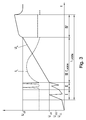
- Fig. 3
- ein schematisches Zeitdiagramm eines Ladeverfahrens;
- Fig. 4
- die Verläufe des Ladestroms, der Ladespannung und des Innenwiderstands einer Batterie in Abhängigkeit des Ladezustands bei einem konventionellen Ladeverfahren mit konstantem Strom;
- Fig. 5
- die Verläufe des Ladestroms, der Ladespannung und des Innenwiderstands eine Batterie in Abhängigkeit des Ladezustands;
- Fig. 6
- eine Variante des Ladeverfahrens mit einer Spannungsrampe mit unterschiedlichen Steigungen;
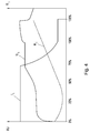
- Fig. 7
- die Verläufe des Ladestroms, der Ladespannung und des Innenwiderstands eine Batterie in Abhängigkeit des Ladezustands bei verschiedenen Alterungszuständen der Batterie;
- Fig. 8
- eine Alternative des Ladeverfahrens mit Strompulsen; und
- Fig. 9
- die zeitlichen Verläufe des Ladestroms und der Ladespannung der Batterie bei einem Beispiel des erfindungsgemäßen Ladeverfahrens.
- Fig. 1
- a block diagram of a device for charging a battery;
- Fig. 2
- the usual course of the internal resistance of a lead-acid battery depending on the state of charge and age of the battery;
- Fig. 3
- a schematic timing diagram of a charging method;
- Fig. 4
- the curves of the charging current, the charging voltage and the internal resistance of a battery as a function of the state of charge in a conventional constant current charging method;
- Fig. 5
- the curves of the charging current, the charging voltage and the internal resistance of a battery as a function of the state of charge;
- Fig. 6
- a variant of the charging method with a voltage ramp with different slopes;
- Fig. 7
- the characteristics of the charging current, the charging voltage and the internal resistance of a battery as a function of the state of charge at different aging states of the battery;
- Fig. 8
- an alternative charging method with current pulses; and
- Fig. 9
- the time profiles of the charging current and the charging voltage of the battery in an example of the charging method according to the invention.
Vor der eigentlichen Ladephase III (Hauptladephase) kann eine Depolarisation der Batterie gemäß Phase II vorgenommen werden. Diese Phase wird insbesondere dann durchgeführt, wenn die Leerlaufspannung ULL der Batterie unter einem bestimmten Grenzwert ULLG liegt. Während der Depolarisationsphase II werden Spannungsrampen an die Batterie angelegt, wodurch ein verschobenes Elektrodenpotential der Batterie ins Gleichgewicht gerückt werden kann. Die Dauer der Depolarisationsphase II wird als Bruchteil der effektiven Ladezeit t'Laden gewählt. Nach Abschluss der Depolarisationsphase II beginnt der eigentliche Ladevorgang III. Die nach der Depolarisationsphase II resultierende Spannung der Batterie ist nunmehr die Ladestartspannung ULA der Ladephase III. Wird keine Depolarisationsphase II vorgenommen, würde die Leerlaufspannung ULL der Batterie als Ladestartspannung ULA herangezogen.Before the actual charging phase III (main charging phase), a depolarization of the battery can be made according to Phase II. This phase is carried out in particular when the open-circuit voltage U LL of the battery is below a certain limit U LLG . During the Depolarisationsphase II voltage ramps are applied to the battery, whereby a shifted electrode potential of the battery can be brought into balance. The duration of the depolarization phase II is selected as a fraction of the effective charging time t ' charging . After completion of the Depolarisationsphase II, the actual charging begins III. The voltage of the battery resulting after the depolarization phase II is now the charging starting voltage U LA of the charging phase III. If no depolarization phase II is carried out, the no-load voltage U LL of the battery would be used as the charge start voltage U LA .
Die Ladespannung UL wird während der Ladezeit t'Laden zwischen der Ladestartspannung ULA und der durch die Batterie festgelegten Ladeschlussspannung ULS erhöht. Die Ladeschlussspannung ULS ist abhängig von der verwendeten Batterietechnologie, der Anzahl der Zellen sowie der Batterietemperatur. Im dargestellten Beispiel wird die Ladespannung UL kontinuierlich und linear zwischen der Ladestartspannung ULA und der Ladeschlussspannung ULS während der Ladezeit t'Laden erhöht. Um einen derartigen linearen Verlauf der Ladespannung UL zu erreichen, muss der Ladestrom IL oder die Ladespannung UL entsprechend geregelt werden, sodass sich der gewünschte Verlauf der Ladespannung UL, wie dargestellt, ergibt. Durch die entsprechende Regelung erfolgt indirekt eine Berücksichtigung des Innenwiderstands Ri der Batterie, ohne dass dieser aber wirklich gemessen wird. Durch die Berücksichtigung des sich ändernden Innenwiderstands RI während des Ladevorgangs III können die Ladungsverluste und somit die Erwärmung der Batterie deutlich reduziert werden. In der Folge kann die Batterielebensdauer entsprechend erhöht werden. Die definitive Zeit t'Laden des Hauptladevorgangs III ist ein Bruchteil der insgesamt zur Verfügung stehenden Ladezeit tLaden, beispielsweise 50-80% davon. Die Nettozeit für den Ladevorgang III wird mit t'Laden gekennzeichnet.The charging voltage U L is increased during the charging time t ' charging between the charging start voltage U LA and the charging end voltage U LS determined by the battery. The end-of-charge voltage U LS depends on the battery technology used, the number of cells and the battery temperature. In the example shown, the charging voltage U L is continuously and linearly increased between the charging starting voltage U LA and the charging end voltage U LS during the charging time t ' charging . In order to achieve such a linear course of the charging voltage U L , the charging current I L or the charging voltage U L must be controlled accordingly, so that the desired course of the charging voltage U L , as shown, results. The corresponding regulation indirectly takes account of the internal resistance R i of the battery, without, however, actually being measured. By taking into account the changing internal resistance R I during the charging process III, the charge losses and thus the heating of the battery can be significantly reduced. As a result, the battery life can be increased accordingly. The definitive time t charging of the main charging III is a fraction of the total charging time t charging available , for example 50-80% thereof. The net time for charging III is marked with t ' loading .
Nach Abschluss des Hauptladeverfahrens in Phase III kann noch ein Nachladevorgang IV zur Vollladung angeschlossen werden. Hier können verschiedene bekannte Verfahren zur Nachladung bzw. Vollladung der Batterie angewendet werden.After completion of the main charging process in phase III, a recharge process IV can be connected to the full charge. Here, various known methods for recharging or full charging the battery can be applied.
Im Vergleich dazu zeigt
In der Realität wird die Ladespannung UL nicht linear ansteigen, sondern entsprechend der Pulse des Ladestromes IL Veränderungen aufweisen. In den Pausen zwischen zwei Strompulsen wird der Innenwiderstand Ri gemessen und in die Regelung des Ladestromes IL miteinbezogen, indem der Ladestrom IL in Abhängigkeit des gemessenen Innenwiderstands Ri geregelt wird. Zur Messung des Innenwiderstands Ri ist eine Absenkung des Stroms auf einen bestimmten Wert ausreichend; es ist nicht erforderlich den Strom auf Null zu reduzieren. Zur Erfassung des komplexen Innenwiderstands Ri der Batterie wird die Spannungsantwort während einer bestimmten Zeit erfasst und daraus der Innenwiderstand Ri berechnet. Anstelle von Strompulsen können auch Spannungspulse eingeprägt werden. Diese Variante ist jedoch von der Regelung aufwendiger.In reality, the charging voltage U L will not increase linearly, but according to the pulses of the charging current I L have changes. In the pauses between two current pulses, the internal resistance R i is measured and included in the regulation of the charging current I L , in that the charging current I L is regulated as a function of the measured internal resistance R i . For measuring the internal resistance R i , a reduction of the current to a certain value is sufficient; it is not necessary to reduce the current to zero. In order to detect the complex internal resistance R i of the battery, the voltage response is detected for a specific time and the internal resistance R i is calculated therefrom. Instead of current pulses voltage pulses can be impressed. However, this variant is more complicated by the regulation.
Schließlich zeigt
Das erfindungsgemäße Ladeverfahren bewirkt einen erhöhten Gesamtwirkungsgrad und aufgrund der dadurch verringerten Temperaturerhöhung, eine Verlängerung der Batterielebensdauer und somit eine Verlängerung der Einsatzfähigkeit der Batterie, beispielsweise in einem Flurförderzeug. In der Folge kommt es in der Batterie auch zu weniger Wasserverlust. Durch die optimale Ausnutzung der gesamten Ladezeit tLaden bzw. Nettoladezeit t'Laden kann die Batterie schonend geladen werden. Durch Ausnutzung von Zeiten, in welchen Energie billiger ist, beispielsweise Nachtstrom, kann es auch zu weiteren wirtschaftlichen Vorteilen kommen. Beispielsweise kann auch vor Einleitung der Ladephase eine Verzögerung um eine Zeitspanne Δtv vorgenommen werden (nicht dargestellt).The charging method according to the invention causes an increased overall efficiency and, due to the thereby reduced temperature increase, an extension of the battery life and thus an extension of the operational capability of the battery, for example in an industrial truck. As a result, there is also less loss of water in the battery. By optimally utilizing the total charging time t charging or net charging time t charging , the battery can be gently charged. By taking advantage of times in which energy is cheaper, such as nighttime electricity, it can also lead to further economic benefits. For example, a delay of a period of time .DELTA.t v can be carried out (not shown) also before the initiation of the charging phase.
Claims (15)
Applications Claiming Priority (2)
| Application Number | Priority Date | Filing Date | Title |
|---|---|---|---|
| ATA50382/2012A AT513335B1 (en) | 2012-09-13 | 2012-09-13 | Method and device for charging batteries |
| EP13791898.3A EP2896105B1 (en) | 2012-09-13 | 2013-09-09 | Method and device for charging batteries |
Related Parent Applications (2)
| Application Number | Title | Priority Date | Filing Date |
|---|---|---|---|
| EP13791898.3A Division EP2896105B1 (en) | 2012-09-13 | 2013-09-09 | Method and device for charging batteries |
| EP13791898.3A Division-Into EP2896105B1 (en) | 2012-09-13 | 2013-09-09 | Method and device for charging batteries |
Publications (1)
| Publication Number | Publication Date |
|---|---|
| EP3136539A1 true EP3136539A1 (en) | 2017-03-01 |
Family
ID=49585227
Family Applications (2)
| Application Number | Title | Priority Date | Filing Date |
|---|---|---|---|
| EP16190154.1A Withdrawn EP3136539A1 (en) | 2012-09-13 | 2013-09-09 | Method and device for the charging of batteries |
| EP13791898.3A Active EP2896105B1 (en) | 2012-09-13 | 2013-09-09 | Method and device for charging batteries |
Family Applications After (1)
| Application Number | Title | Priority Date | Filing Date |
|---|---|---|---|
| EP13791898.3A Active EP2896105B1 (en) | 2012-09-13 | 2013-09-09 | Method and device for charging batteries |
Country Status (5)
| Country | Link |
|---|---|
| US (1) | US9537342B2 (en) |
| EP (2) | EP3136539A1 (en) |
| CN (1) | CN104769806B (en) |
| AT (1) | AT513335B1 (en) |
| WO (1) | WO2014040104A2 (en) |
Cited By (1)
| Publication number | Priority date | Publication date | Assignee | Title |
|---|---|---|---|---|
| DE102019218489A1 (en) * | 2019-11-28 | 2021-06-02 | Robert Bosch Gmbh | Method and device for charging a battery for a vehicle |
Families Citing this family (9)
| Publication number | Priority date | Publication date | Assignee | Title |
|---|---|---|---|---|
| DE102014205167A1 (en) * | 2014-03-20 | 2015-09-24 | Robert Bosch Gmbh | A method of recharging battery cells and charge controllers used in vehicles to carry out such a method |
| DE102016205374A1 (en) * | 2016-03-31 | 2017-10-05 | Siemens Aktiengesellschaft | Method and device for charging a battery |
| KR102285148B1 (en) * | 2016-08-22 | 2021-08-04 | 삼성에스디아이 주식회사 | Battery charging method and battery charging apparatus using the same |
| US10449615B2 (en) * | 2016-10-31 | 2019-10-22 | Illinois Tool Works Inc. | Hybrid welding modules |
| US11223220B2 (en) | 2016-10-31 | 2022-01-11 | Illinois Tool Works Inc. | Hybrid welding systems and portable hybrid welding modules |
| TWI625915B (en) * | 2016-11-18 | 2018-06-01 | Industrial Technology Research Institute | Smart charging method |
| CN107394854A (en) * | 2017-08-31 | 2017-11-24 | 江苏聚合新能源科技有限公司 | A kind of natural charging method of battery dynamic and system |
| CN111525654B (en) * | 2020-06-02 | 2023-08-22 | 西安稳先半导体科技有限责任公司 | Circuit and method for time-sharing charging of batteries in battery pack |
| DE102022200867A1 (en) * | 2022-01-26 | 2023-07-27 | Volkswagen Aktiengesellschaft | Method and device for charging a multi-cell battery |
Citations (7)
| Publication number | Priority date | Publication date | Assignee | Title |
|---|---|---|---|---|
| WO1996016460A1 (en) | 1994-11-21 | 1996-05-30 | PREMIER ENGINEERED PRODUCTS, INC. doing business as PREMIER ENGINEERING PRODUCTS CORPORATION | Battery charging method and charger |
| EP1104074A1 (en) | 1999-05-07 | 2001-05-30 | Tai-Her Yang | Voltage limiter for use in circuits permissive of linear adjustments in parallel with battery sets |
| JP2008061373A (en) | 2006-08-31 | 2008-03-13 | Nagano Japan Radio Co | Charging device |
| JP2008187811A (en) * | 2007-01-30 | 2008-08-14 | Nagano Japan Radio Co | Charging apparatus |
| EP2164152A2 (en) * | 2008-09-16 | 2010-03-17 | Commissariat à l'Energie Atomique | Method for pulsed charging of a battery in a standalone system comprising a supercapacitor |
| EP2244329A1 (en) | 2009-04-20 | 2010-10-27 | Deutronic Elektronik GmbH | Charging and diagnosis method for batteries |
| DE102009051731A1 (en) | 2009-11-03 | 2011-05-05 | Bayerische Motoren Werke Aktiengesellschaft | Method for charging e.g. lead-acid battery of motor vehicle, involves determining constant charging voltage of battery in charging phase from maximum allowable charging voltage, constant-current charging voltage and charging voltage |
Family Cites Families (11)
| Publication number | Priority date | Publication date | Assignee | Title |
|---|---|---|---|---|
| US5583416A (en) * | 1994-01-26 | 1996-12-10 | Gnb Battery Technologies, Inc. | Apparatus and method for step-charging batteries to optimize charge acceptance |
| JP3554057B2 (en) * | 1995-02-06 | 2004-08-11 | 本田技研工業株式会社 | Battery charging control device for electric vehicles |
| US6307352B1 (en) * | 1999-10-19 | 2001-10-23 | Enrev Corporation | High energy charge and depolarization pulse conditioner for an enhanced-reliability lead-acid battery charger |
| JP4292721B2 (en) * | 2001-02-14 | 2009-07-08 | 株式会社日本自動車部品総合研究所 | Battery state control method for hybrid vehicle |
| JP4523738B2 (en) * | 2001-06-07 | 2010-08-11 | パナソニック株式会社 | Secondary battery remaining capacity control method and apparatus |
| CN1272887C (en) * | 2002-12-31 | 2006-08-30 | 广达电脑股份有限公司 | Two section type charging device |
| US8217631B2 (en) * | 2008-01-22 | 2012-07-10 | Honda Motor Co., Ltd. | ACG output voltage control |
| US7808244B2 (en) * | 2008-03-31 | 2010-10-05 | Texas Instruments Incorporated | System and method for determining state of charge of a battery utilizing initial voltage and current measurement and a previous estimate of battery resistance |
| US20120098501A1 (en) * | 2010-10-26 | 2012-04-26 | Tesla Motors, Inc. | Efficient lead acid battery charging |
| CN202014109U (en) * | 2011-03-02 | 2011-10-19 | 江苏嘉钰新能源技术有限公司 | Power supply capable of adjusting charging voltage of battery |
| DE102011013967A1 (en) * | 2011-03-15 | 2012-01-05 | Daimler Ag | Maximum current determination method for high voltage battery of motor car, involves determining maximum current from given voltage threshold value, computed open cell voltage and internal resistance of single cells of battery |
-
2012
- 2012-09-13 AT ATA50382/2012A patent/AT513335B1/en active
-
2013
- 2013-09-09 US US14/427,676 patent/US9537342B2/en active Active
- 2013-09-09 WO PCT/AT2013/050176 patent/WO2014040104A2/en active Application Filing
- 2013-09-09 EP EP16190154.1A patent/EP3136539A1/en not_active Withdrawn
- 2013-09-09 CN CN201380057844.3A patent/CN104769806B/en active Active
- 2013-09-09 EP EP13791898.3A patent/EP2896105B1/en active Active
Patent Citations (8)
| Publication number | Priority date | Publication date | Assignee | Title |
|---|---|---|---|---|
| WO1996016460A1 (en) | 1994-11-21 | 1996-05-30 | PREMIER ENGINEERED PRODUCTS, INC. doing business as PREMIER ENGINEERING PRODUCTS CORPORATION | Battery charging method and charger |
| EP1104074A1 (en) | 1999-05-07 | 2001-05-30 | Tai-Her Yang | Voltage limiter for use in circuits permissive of linear adjustments in parallel with battery sets |
| JP2008061373A (en) | 2006-08-31 | 2008-03-13 | Nagano Japan Radio Co | Charging device |
| JP2008187811A (en) * | 2007-01-30 | 2008-08-14 | Nagano Japan Radio Co | Charging apparatus |
| EP2164152A2 (en) * | 2008-09-16 | 2010-03-17 | Commissariat à l'Energie Atomique | Method for pulsed charging of a battery in a standalone system comprising a supercapacitor |
| US20100066309A1 (en) | 2008-09-16 | 2010-03-18 | Commissariat A L'energie Atomique | Method for pulsed charging of a battery in an autonomous system comprising a supercapacitance |
| EP2244329A1 (en) | 2009-04-20 | 2010-10-27 | Deutronic Elektronik GmbH | Charging and diagnosis method for batteries |
| DE102009051731A1 (en) | 2009-11-03 | 2011-05-05 | Bayerische Motoren Werke Aktiengesellschaft | Method for charging e.g. lead-acid battery of motor vehicle, involves determining constant charging voltage of battery in charging phase from maximum allowable charging voltage, constant-current charging voltage and charging voltage |
Cited By (2)
| Publication number | Priority date | Publication date | Assignee | Title |
|---|---|---|---|---|
| DE102019218489A1 (en) * | 2019-11-28 | 2021-06-02 | Robert Bosch Gmbh | Method and device for charging a battery for a vehicle |
| US11628742B2 (en) | 2019-11-28 | 2023-04-18 | Robert Bosch Gmbh | Method and device for charging a battery for a means of transport |
Also Published As
| Publication number | Publication date |
|---|---|
| AT513335B1 (en) | 2017-10-15 |
| AT513335A1 (en) | 2014-03-15 |
| CN104769806B (en) | 2018-02-13 |
| US9537342B2 (en) | 2017-01-03 |
| WO2014040104A2 (en) | 2014-03-20 |
| CN104769806A (en) | 2015-07-08 |
| EP2896105A2 (en) | 2015-07-22 |
| EP2896105B1 (en) | 2017-08-23 |
| US20150249349A1 (en) | 2015-09-03 |
| WO2014040104A3 (en) | 2014-10-16 |
Similar Documents
| Publication | Publication Date | Title |
|---|---|---|
| EP2896105B1 (en) | Method and device for charging batteries | |
| EP3445607B1 (en) | Battery charging system and corresponding method | |
| DE3031887C2 (en) | Procedure for charging a traction battery | |
| EP3275040B1 (en) | Method and device for forming a battery | |
| DE102017222975A1 (en) | Control device, balance correction device, electrical storage system and device | |
| EP2531869B1 (en) | Device and method for determining a range of a battery characteristic curve | |
| DE102018127530A1 (en) | Calculation of the maximum current and power forecast for a battery pack | |
| EP2884620B1 (en) | Method for the charging of batteries and converter for charging | |
| DE102011001472A1 (en) | loader | |
| DE112019005307T5 (en) | Power supply system and power source forming it | |
| DE102011012316A1 (en) | Method and device for charging a low-voltage battery in an electric drive system | |
| EP3708416A1 (en) | Method and charging device for determining a maximum storage capacity of an energy storage device | |
| EP2353215B1 (en) | System for monitoring capacitor cells | |
| DE112015002996T5 (en) | BALANCING CORRECTION CONTROL DEVICE, BALANCING CORRECTION SYSTEM AND ELECTRICAL STORAGE SYSTEM | |
| EP2856189B1 (en) | Method and device for determining the actual capacity of a battery | |
| WO2019072488A1 (en) | Energy storage device and device and method for determining a capacitance of an energy storage device | |
| WO2020239577A1 (en) | Battery management system and operating an energy store for electrical energy | |
| DE102018129426B3 (en) | Process for active charge balancing in energy stores | |
| DE102016001123A1 (en) | A method of charging a battery of a motor vehicle by means of a motor vehicle side solar device and motor vehicle | |
| DE102017222217A1 (en) | Method for charging a battery, evaluation unit of a power grid and automobile | |
| DE4339363A1 (en) | Charging procedure for accumulators | |
| EP3772174A1 (en) | Control device, inverter, arrangement with an inverter and an electric machine, method for operating an inverter and computer program | |
| DE102019216394A1 (en) | Method for regulating the state of charge of a vehicle battery | |
| DE102008040696A1 (en) | Generator output voltage regulating method for motor vehicle, involves regulating charge condition value of battery of motor vehicle to preset charge condition value by battery regulator | |
| EP4138258B1 (en) | Battery management system and method for controlling a charging current threshold for a battery management system |
Legal Events
| Date | Code | Title | Description |
|---|---|---|---|
| PUAI | Public reference made under article 153(3) epc to a published international application that has entered the european phase |
Free format text: ORIGINAL CODE: 0009012 |
|
| STAA | Information on the status of an ep patent application or granted ep patent |
Free format text: STATUS: THE APPLICATION HAS BEEN PUBLISHED |
|
| AC | Divisional application: reference to earlier application |
Ref document number: 2896105 Country of ref document: EP Kind code of ref document: P |
|
| AK | Designated contracting states |
Kind code of ref document: A1 Designated state(s): AL AT BE BG CH CY CZ DE DK EE ES FI FR GB GR HR HU IE IS IT LI LT LU LV MC MK MT NL NO PL PT RO RS SE SI SK SM TR |
|
| RIN1 | Information on inventor provided before grant (corrected) |
Inventor name: BINDER, JUERGEN Inventor name: EITELSEBNER, DAVID |
|
| STAA | Information on the status of an ep patent application or granted ep patent |
Free format text: STATUS: THE APPLICATION IS DEEMED TO BE WITHDRAWN |
|
| 18D | Application deemed to be withdrawn |
Effective date: 20170902 |