EP3136538A1 - An intermediate circuit system - Google Patents
An intermediate circuit system Download PDFInfo
- Publication number
- EP3136538A1 EP3136538A1 EP15182112.1A EP15182112A EP3136538A1 EP 3136538 A1 EP3136538 A1 EP 3136538A1 EP 15182112 A EP15182112 A EP 15182112A EP 3136538 A1 EP3136538 A1 EP 3136538A1
- Authority
- EP
- European Patent Office
- Prior art keywords
- pole
- inductive element
- intermediate circuit
- circuit system
- controllable
- Prior art date
- Legal status (The legal status is an assumption and is not a legal conclusion. Google has not performed a legal analysis and makes no representation as to the accuracy of the status listed.)
- Withdrawn
Links
Images
Classifications
-
- H—ELECTRICITY
- H02—GENERATION; CONVERSION OR DISTRIBUTION OF ELECTRIC POWER
- H02J—CIRCUIT ARRANGEMENTS OR SYSTEMS FOR SUPPLYING OR DISTRIBUTING ELECTRIC POWER; SYSTEMS FOR STORING ELECTRIC ENERGY
- H02J7/00—Circuit arrangements for charging or depolarising batteries or for supplying loads from batteries
- H02J7/34—Parallel operation in networks using both storage and other dc sources, e.g. providing buffering
- H02J7/345—Parallel operation in networks using both storage and other dc sources, e.g. providing buffering using capacitors as storage or buffering devices
-
- B—PERFORMING OPERATIONS; TRANSPORTING
- B60—VEHICLES IN GENERAL
- B60L—PROPULSION OF ELECTRICALLY-PROPELLED VEHICLES; SUPPLYING ELECTRIC POWER FOR AUXILIARY EQUIPMENT OF ELECTRICALLY-PROPELLED VEHICLES; ELECTRODYNAMIC BRAKE SYSTEMS FOR VEHICLES IN GENERAL; MAGNETIC SUSPENSION OR LEVITATION FOR VEHICLES; MONITORING OPERATING VARIABLES OF ELECTRICALLY-PROPELLED VEHICLES; ELECTRIC SAFETY DEVICES FOR ELECTRICALLY-PROPELLED VEHICLES
- B60L15/00—Methods, circuits, or devices for controlling the traction-motor speed of electrically-propelled vehicles
- B60L15/007—Physical arrangements or structures of drive train converters specially adapted for the propulsion motors of electric vehicles
-
- H—ELECTRICITY
- H02—GENERATION; CONVERSION OR DISTRIBUTION OF ELECTRIC POWER
- H02J—CIRCUIT ARRANGEMENTS OR SYSTEMS FOR SUPPLYING OR DISTRIBUTING ELECTRIC POWER; SYSTEMS FOR STORING ELECTRIC ENERGY
- H02J1/00—Circuit arrangements for dc mains or dc distribution networks
- H02J1/10—Parallel operation of dc sources
- H02J1/102—Parallel operation of dc sources being switching converters
-
- H—ELECTRICITY
- H02—GENERATION; CONVERSION OR DISTRIBUTION OF ELECTRIC POWER
- H02M—APPARATUS FOR CONVERSION BETWEEN AC AND AC, BETWEEN AC AND DC, OR BETWEEN DC AND DC, AND FOR USE WITH MAINS OR SIMILAR POWER SUPPLY SYSTEMS; CONVERSION OF DC OR AC INPUT POWER INTO SURGE OUTPUT POWER; CONTROL OR REGULATION THEREOF
- H02M3/00—Conversion of dc power input into dc power output
- H02M3/02—Conversion of dc power input into dc power output without intermediate conversion into ac
- H02M3/04—Conversion of dc power input into dc power output without intermediate conversion into ac by static converters
- H02M3/10—Conversion of dc power input into dc power output without intermediate conversion into ac by static converters using discharge tubes with control electrode or semiconductor devices with control electrode
- H02M3/145—Conversion of dc power input into dc power output without intermediate conversion into ac by static converters using discharge tubes with control electrode or semiconductor devices with control electrode using devices of a triode or transistor type requiring continuous application of a control signal
- H02M3/155—Conversion of dc power input into dc power output without intermediate conversion into ac by static converters using discharge tubes with control electrode or semiconductor devices with control electrode using devices of a triode or transistor type requiring continuous application of a control signal using semiconductor devices only
- H02M3/156—Conversion of dc power input into dc power output without intermediate conversion into ac by static converters using discharge tubes with control electrode or semiconductor devices with control electrode using devices of a triode or transistor type requiring continuous application of a control signal using semiconductor devices only with automatic control of output voltage or current, e.g. switching regulators
- H02M3/158—Conversion of dc power input into dc power output without intermediate conversion into ac by static converters using discharge tubes with control electrode or semiconductor devices with control electrode using devices of a triode or transistor type requiring continuous application of a control signal using semiconductor devices only with automatic control of output voltage or current, e.g. switching regulators including plural semiconductor devices as final control devices for a single load
- H02M3/1582—Buck-boost converters
-
- B—PERFORMING OPERATIONS; TRANSPORTING
- B60—VEHICLES IN GENERAL
- B60L—PROPULSION OF ELECTRICALLY-PROPELLED VEHICLES; SUPPLYING ELECTRIC POWER FOR AUXILIARY EQUIPMENT OF ELECTRICALLY-PROPELLED VEHICLES; ELECTRODYNAMIC BRAKE SYSTEMS FOR VEHICLES IN GENERAL; MAGNETIC SUSPENSION OR LEVITATION FOR VEHICLES; MONITORING OPERATING VARIABLES OF ELECTRICALLY-PROPELLED VEHICLES; ELECTRIC SAFETY DEVICES FOR ELECTRICALLY-PROPELLED VEHICLES
- B60L2210/00—Converter types
- B60L2210/10—DC to DC converters
-
- H—ELECTRICITY
- H02—GENERATION; CONVERSION OR DISTRIBUTION OF ELECTRIC POWER
- H02J—CIRCUIT ARRANGEMENTS OR SYSTEMS FOR SUPPLYING OR DISTRIBUTING ELECTRIC POWER; SYSTEMS FOR STORING ELECTRIC ENERGY
- H02J2310/00—The network for supplying or distributing electric power characterised by its spatial reach or by the load
- H02J2310/40—The network being an on-board power network, i.e. within a vehicle
- H02J2310/42—The network being an on-board power network, i.e. within a vehicle for ships or vessels
-
- Y—GENERAL TAGGING OF NEW TECHNOLOGICAL DEVELOPMENTS; GENERAL TAGGING OF CROSS-SECTIONAL TECHNOLOGIES SPANNING OVER SEVERAL SECTIONS OF THE IPC; TECHNICAL SUBJECTS COVERED BY FORMER USPC CROSS-REFERENCE ART COLLECTIONS [XRACs] AND DIGESTS
- Y02—TECHNOLOGIES OR APPLICATIONS FOR MITIGATION OR ADAPTATION AGAINST CLIMATE CHANGE
- Y02T—CLIMATE CHANGE MITIGATION TECHNOLOGIES RELATED TO TRANSPORTATION
- Y02T10/00—Road transport of goods or passengers
- Y02T10/60—Other road transportation technologies with climate change mitigation effect
- Y02T10/64—Electric machine technologies in electromobility
-
- Y—GENERAL TAGGING OF NEW TECHNOLOGICAL DEVELOPMENTS; GENERAL TAGGING OF CROSS-SECTIONAL TECHNOLOGIES SPANNING OVER SEVERAL SECTIONS OF THE IPC; TECHNICAL SUBJECTS COVERED BY FORMER USPC CROSS-REFERENCE ART COLLECTIONS [XRACs] AND DIGESTS
- Y02—TECHNOLOGIES OR APPLICATIONS FOR MITIGATION OR ADAPTATION AGAINST CLIMATE CHANGE
- Y02T—CLIMATE CHANGE MITIGATION TECHNOLOGIES RELATED TO TRANSPORTATION
- Y02T10/00—Road transport of goods or passengers
- Y02T10/60—Other road transportation technologies with climate change mitigation effect
- Y02T10/72—Electric energy management in electromobility
Definitions
- the disclosure relates generally to electromechanical power transmission systems. More particularly, the invention relates to an intermediate circuit system that can be, for example but not necessarily, a part of an electromechanical power transmission system of a ship.
- an electromechanical power transmission system comprises generators driven with combustion engines, a direct voltage intermediate circuit system, and first electric equipment for transferring electrical power from the generators to the intermediate circuit system.
- the generators can be for example synchronous or asynchronous alternating current "AC" generators and the above-mentioned first electric equipment may comprise power electronic converters for converting the alternating voltages of the generators into direct voltage suitable for the intermediate circuit system.
- the intermediate circuit system comprises typically one or more capacitor systems connected between positive and negative poles of the intermediate circuit system. Each capacitor system comprises typically a plurality of series and/or parallel connected capacitor units.
- the electromechanical power transmission system comprises second electric equipment for transferring electrical power from the intermediate circuit system to power consuming electric appliances, such as for example electric motors and lighting systems.
- the second electric equipment may comprise for example power electronic converters for converting the direct voltage of the intermediate circuit system into voltages suitable for the power consuming electric appliances.
- An electromechanical power transmission system of the kind described above can be for example a part of a power system of a ship where one or more electric motors of the power system are arranged to drive one or more propellers.
- the above-mentioned intermediate circuit system is typically arranged to comprise portions which are electrically separable from each other. This arrangement enables fault isolation so that a faulty portion of the power transmission system can be electrically separated from the other portions of the power transmission system.
- the portions of the intermediate circuit system are advantageously electrically interconnected so as to provide more effective mutual power balancing between the power consuming electric appliances, such as for example electric motors and lighting systems.
- the mutual power balancing between the power consuming electric appliances is based on the improbability of simultaneous peak-loads of many power consuming electric appliances. The higher is the number of the power consuming electric appliances supplied by the electrically interconnected portions of the intermediate circuit system, the more effective is the power balancing. Therefore, the portions of the intermediate circuit system should be electrically connectable to each other and, when needed, electrically separable from each other.
- An intermediate circuit system that can be, for example but not necessarily, a part of an electromechanical power transmission system of a ship.
- An intermediate circuit system according to the invention comprises:
- the coupling circuit comprises an inductive element, a first controllable switch between a first end of the inductive element and the first pole, and a second controllable switch between the second end of the inductive element and the third pole.
- the coupling circuit further comprises a first switching component for conducting current from the second pole to the first end of the inductive element and a second switching component for conducting current from the second pole to the second end of the inductive element.
- the above-described coupling circuit provided with the first and second controllable switches can be used for electrically interconnecting the first and second capacitor systems and for electrically disconnecting the first and second capacitor systems from each other. Furthermore, the coupling circuit can be used as a chopper circuit between the first and second capacitor systems for example in a case where there are different voltages in the first and second capacitor systems and the first and second capacitor systems are wanted to be electrically interconnected.
- capacitor systems there can be more than two capacitor systems and more than one coupling circuit. It is also possible that the capacitor systems are arranged to constitute a ring where one of the capacitor systems can be electrically disconnected from the other capacitor systems so that the other capacitor systems still remain electrically interconnected.
- the above-mentioned first and second switching components are controllable switches each being controllable to conduct current to the above-mentioned second pole.
- the coupling circuit can be used not only as a buck chopper for transferring electrical energy from one of the above-mentioned capacitor systems having higher voltage to the other of the capacitor systems having lower voltage but also as a boost chopper for transferring electrical energy from the capacitor system having the lower voltage to the capacitor system having the higher voltage.
- An electromechanical power transmission system that can be, for example but not necessarily, a part of a power system of a ship.
- An electromechanical power transmission system according to the invention comprises, among others, an intermediate circuit system according to the invention, where each coupling circuit of the intermediate circuit system is suitable for electrically interconnecting portions of the electromechanical power transmission system and, when needed e.g. in a fault situation, for electrically disconnecting the portions of the electromechanical power transmission system from each other.
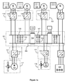
- FIG. 1a shows a schematic illustration of an exemplifying electromechanical power transmission system that comprises an intermediate circuit system 101 according to an exemplifying and non-limiting embodiment of the invention.
- the electromechanical power transmission system comprises first generators 114 and 115 that are driven with combustion engines 123 and 124, and a second generator 116 that is driven with a combustion engine 124.
- the generators can be for example synchronous generators or asynchronous generators and the combustion engines can be for example diesel engines or Otto-cycle engines.
- the electromechanical power transmission system comprises electric appliances to be supplied with electrical power.
- first and second ones of the electric appliances 117 and 118 comprise electric motors 126 and 127 arranged to drive propellers.
- this exemplifying electromechanical power transmission system comprises means for energizing a lighting system 128.
- the electromechanical power transmission system comprises first electric equipment 119 for transferring electrical power from the generators 114 and 115 to the intermediate circuit system 101 via a first pole 105 and a second pole 106 of the intermediate circuit system.
- the electromechanical power transmission system comprises second electric equipment 120 for transferring electrical power from the generator 116 to the intermediate circuit system 101 via a third pole 107 and the second pole 106 of the intermediate circuit system.
- the electric equipment 119 and the electric equipment 120 comprise power electronic converters 129, 130, and 131 for converting the alternating voltages of the generators 114, 115, and 116 into direct voltage suitable for the intermediate circuit system 101.
- the electromechanical power transmission system comprises third electric equipment 121 for transferring electrical power from the intermediate circuit system 101 to the electric appliance 117 via the poles 105 and 106 of the intermediate circuit system, and fourth electric equipment 122 for transferring electrical power from the intermediate circuit system to the electric appliance 118 via the poles 107 and 106 of the intermediate circuit system.
- the electric equipment 121 and the electric equipment 122 comprise power electronic converters 132 and 133 for converting the direct voltage of the intermediate circuit system into voltages suitable for the electric motors 126 and 127.
- the intermediate circuit system 101 comprises a first capacitor system 102 between the poles 105 and 106, and a second capacitor system 103 between the poles 107 and 106 as illustrated in figure 1a .
- each capacitor system comprises a plurality of series and parallel connected capacitor units.
- the intermediate circuit system 101 comprises a coupling circuit 104 between the poles 105 and 107.
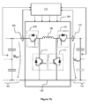
- the circuit diagram of the coupling circuit 104 is shown in figure 1 b.
- the coupling circuit 104 comprises an inductive element 108, a first controllable switch 109 between a first end of the inductive element and the pole 105, and a second controllable switch 110 between the second end of the inductive element and the pole 107.
- the inductive element 108 may comprise an inductor coil or two or more inductor coils connected in parallel and/or in series.
- the coupling circuit further comprises a first switching component 111 for conducting current from the pole 106 to the first end of the inductive element 108 and a second switching component 112 for conducting current from the pole 106 to the second end of the inductive element 108.
- the controllable switch 109 is controllable to be unidirectionally conductive in the direction from the inductive element 108 to the pole 105 and controllable to be bi-directionally conductive in the both directions between the inductive element 108 and the pole 105.
- the controllable switch 110 is controllable to be unidirectionally conductive in the direction from the inductive element 108 to the pole 107 and controllable to be bi-directionally conductive in the both directions between the inductive element 108 and the pole 107.
- the controllable switch 109 comprises a diode having its forward direction from the inductive element 108 to the pole 105 and a controllable semiconductor component in parallel with the diode.
- the controllable switch 110 comprises a diode having its forward direction from the inductive element 108 to the pole 107 and a controllable semiconductor component in parallel with the diode.
- the controllable semiconductor components of the switches 109 and 110 can be for example insulated gate bipolar transistors "IGBT”, gate turn-off thyristors "GTO”, bipolar transistors, or field-effect transistors.
- the switching component 111 is controllable to be unidirectionally conductive in the direction from the pole 106 to the first end of the inductive element 108 and controllable to be bi-directionally conductive in the both directions between the first end of the inductive element 108 and the pole 106.
- the switching component 112 is controllable to be unidirectionally conductive in the direction from the pole 106 to the second end of the inductive element 108 and controllable to be bi-directionally conductive in the both directions between the second end of the inductive element 108 and the pole 106.
- the switching component 111 comprises a diode having its forward direction from the pole 106 to the first end of the inductive element 108 and a controllable semiconductor component in parallel with the diode.
- the switching component 112 comprises a diode having its forward direction from the pole 106 to the second end of the inductive element 108 and a controllable semiconductor component in parallel with the diode.
- the controllable semiconductor components of the switching components 111 and 112 can be for example insulated gate bipolar transistors "IGBT”, gate turn-off thyristors "GTO”, bipolar transistors, or field-effect transistors.
- the intermediate circuit system comprises a controller 113 for controlling the operation of the coupling circuit 104.
- the operation of the coupling circuit 104 in two exemplifying situations is described below with reference to figure 1 b.
- the direct voltage U DC1 is assumed to be higher than the direct voltage U DC2 . Furthermore, it is assumed that there is a need to transfer electrical energy from the capacitor system 102 to the capacitor system 103.
- the switching components 111 and 112 are controlled to be unidirectionally conductive, i.e. the controllable semiconductor components of the switching components 111 and 112 are controlled to be non-conductive.
- the switch 109 is controlled to be in turn conductive in the direction from the pole 105 to the inductive element 108 and in turn non-conductive in the direction from the pole 105 to the inductive element.
- the coupling circuit 104 is controlled to operate as a buck chopper that transfers electrical energy from the capacitor system 102 having the higher voltage U DC1 to the capacitor system 103 having the lower voltage U DC2 . It is worth noting that the coupling circuit 104 is capable of operating as a buck chopper also in a case where the switching components 111 and 112 are non-controllable unidirectionally conductive components, such as for example diodes, without any parallel connected controllable semiconductor components.
- the direct voltage U DC1 is assumed to be lower than the direct voltage U DC2 , and furthermore it is assumed that there is a need to transfer electrical energy from the capacitor system 102 to the capacitor system 103.
- the switch 109 is controlled to be bi-directionally conductive, i.e. the controllable semiconductor component of the switch 109 is controlled to be conductive, and the switching component 111 is controlled to be unidirectionally conductive, i.e. the controllable semiconductor component of the switching component 111 is controlled to be non-conductive.
- the switch 110 is controlled to be unidirectionally conductive, i.e.
- the controllable semiconductor component of the switch 110 is controlled to be non-conductive, and the switching component 112 is controlled to be in turn conductive in the direction from the second end of the inductive element 108 to the pole 106 and in turn non-conductive in the direction from the second end of the inductive element 108 to the pole 106. Therefore, in this exemplifying situation, the coupling circuit 104 is controlled to operate as a boost chopper that transfers electrical energy from the capacitor system 102 having the lower voltage U DC1 to the capacitor system 103 having the higher voltage U DC2 .
- the controller 113 can be implemented with one or more processor circuits each of which can be a programmable processor circuit provided with appropriate software, a dedicated hardware processor such as for example an application specific integrated circuit "ASIC", or a configurable hardware processor such as for example a field programmable gate array "FPGA”. Furthermore, the controller 113 may comprise one or more memory circuits. In the exemplifying case illustrated in figure 1 b , the currents of the controllable switches 109 and 110 and the voltages of the capacitor systems 102 and 103 are measured and the signals indicative of the measured currents and voltages are delivered to the controller 113 so as to enable to controller 113 to control the coupling circuit 104 in an appropriate way in each situation.
Landscapes
- Engineering & Computer Science (AREA)
- Power Engineering (AREA)
- Transportation (AREA)
- Mechanical Engineering (AREA)
- Power Conversion In General (AREA)
Abstract
An intermediate circuit system comprises a first capacitor system (102) between a first pole (105) and a second pole (106), a second capacitor system (103) between a third pole (107) and the second pole, and a coupling circuit (104) between the first and third poles. The coupling circuit comprises an inductive element (108), a controllable switch (109) between a first end of the inductive element and the first pole, and another controllable switch (110) between the second end of the inductive element and the third pole. The coupling circuit further comprises a switching component (111) for conducting current from the second pole to the first end of the inductive element and another switching component (112) for conducting current from the second pole to the second end of the inductive element. Thus, the coupling circuit is capable of acting as a chopper circuit between the first and second capacitor systems.
The figure proposed to be presented with the abstract: Figure 1 b.
Description
- The disclosure relates generally to electromechanical power transmission systems. More particularly, the invention relates to an intermediate circuit system that can be, for example but not necessarily, a part of an electromechanical power transmission system of a ship.
- In many cases, an electromechanical power transmission system comprises generators driven with combustion engines, a direct voltage intermediate circuit system, and first electric equipment for transferring electrical power from the generators to the intermediate circuit system. The generators can be for example synchronous or asynchronous alternating current "AC" generators and the above-mentioned first electric equipment may comprise power electronic converters for converting the alternating voltages of the generators into direct voltage suitable for the intermediate circuit system. The intermediate circuit system comprises typically one or more capacitor systems connected between positive and negative poles of the intermediate circuit system. Each capacitor system comprises typically a plurality of series and/or parallel connected capacitor units. Furthermore, the electromechanical power transmission system comprises second electric equipment for transferring electrical power from the intermediate circuit system to power consuming electric appliances, such as for example electric motors and lighting systems. The second electric equipment may comprise for example power electronic converters for converting the direct voltage of the intermediate circuit system into voltages suitable for the power consuming electric appliances. An electromechanical power transmission system of the kind described above can be for example a part of a power system of a ship where one or more electric motors of the power system are arranged to drive one or more propellers.
- The above-mentioned intermediate circuit system is typically arranged to comprise portions which are electrically separable from each other. This arrangement enables fault isolation so that a faulty portion of the power transmission system can be electrically separated from the other portions of the power transmission system. On the other hand, when there is no fault, the portions of the intermediate circuit system are advantageously electrically interconnected so as to provide more effective mutual power balancing between the power consuming electric appliances, such as for example electric motors and lighting systems. The mutual power balancing between the power consuming electric appliances is based on the improbability of simultaneous peak-loads of many power consuming electric appliances. The higher is the number of the power consuming electric appliances supplied by the electrically interconnected portions of the intermediate circuit system, the more effective is the power balancing. Therefore, the portions of the intermediate circuit system should be electrically connectable to each other and, when needed, electrically separable from each other.
- The following presents a simplified summary in order to provide basic understanding of some aspects of various invention embodiments. The summary is not an extensive overview of the invention. It is neither intended to identify key or critical elements of the invention nor to delineate the scope of the invention. The following summary merely presents some concepts of the invention in a simplified form as a prelude to a more detailed description of exemplifying embodiments of the invention.
- In accordance with the invention, there is provided a new intermediate circuit system that can be, for example but not necessarily, a part of an electromechanical power transmission system of a ship. An intermediate circuit system according to the invention comprises:
- a first capacitor system between a first pole and a second pole,
- a second capacitor system between a third pole and the second pole, and
- a coupling circuit between the first and third poles.
- The coupling circuit comprises an inductive element, a first controllable switch between a first end of the inductive element and the first pole, and a second controllable switch between the second end of the inductive element and the third pole. The coupling circuit further comprises a first switching component for conducting current from the second pole to the first end of the inductive element and a second switching component for conducting current from the second pole to the second end of the inductive element.
- The above-described coupling circuit provided with the first and second controllable switches can be used for electrically interconnecting the first and second capacitor systems and for electrically disconnecting the first and second capacitor systems from each other. Furthermore, the coupling circuit can be used as a chopper circuit between the first and second capacitor systems for example in a case where there are different voltages in the first and second capacitor systems and the first and second capacitor systems are wanted to be electrically interconnected.
- It is to be noted that there can be more than two capacitor systems and more than one coupling circuit. It is also possible that the capacitor systems are arranged to constitute a ring where one of the capacitor systems can be electrically disconnected from the other capacitor systems so that the other capacitor systems still remain electrically interconnected.
- In an intermediate circuit system according to an advantageous and non-limiting embodiment of the invention, the above-mentioned first and second switching components are controllable switches each being controllable to conduct current to the above-mentioned second pole. In this case, the coupling circuit can be used not only as a buck chopper for transferring electrical energy from one of the above-mentioned capacitor systems having higher voltage to the other of the capacitor systems having lower voltage but also as a boost chopper for transferring electrical energy from the capacitor system having the lower voltage to the capacitor system having the higher voltage.
- In accordance with the invention, there is provided also a new electromechanical power transmission system that can be, for example but not necessarily, a part of a power system of a ship. An electromechanical power transmission system according to the invention comprises, among others, an intermediate circuit system according to the invention, where each coupling circuit of the intermediate circuit system is suitable for electrically interconnecting portions of the electromechanical power transmission system and, when needed e.g. in a fault situation, for electrically disconnecting the portions of the electromechanical power transmission system from each other.
- In accordance with the invention, there is provided also a new ship that comprises an electromechanical power transmission system according to the invention.
- A number of exemplifying and non-limiting embodiments of the invention are described in accompanied dependent claims.
- Various exemplifying and non-limiting embodiments of the invention both as to constructions and to methods of operation, together with additional objects and advantages thereof, will be best understood from the following description of specific exemplifying and non-limiting embodiments when read in connection with the accompanying drawings.
- The verbs "to comprise" and "to include" are used in this document as open limitations that neither exclude nor require the existence of unrecited features. The features recited in dependent claims are mutually freely combinable unless otherwise explicitly stated. Furthermore, it is to be understood that the use of "a" or "an", i.e. a singular form, throughout this document does not exclude a plurality.
- Exemplifying and non-limiting embodiments of the invention and their advantages are explained in greater detail below in the sense of examples and with reference to the accompanying drawings, in which:
-
figure 1a shows a schematic illustration of an exemplifying electromechanical power transmission system that comprises an intermediate circuit system according to an exemplifying and non-limiting embodiment of the invention, and -
figure 1b shows a schematic illustration of a part of the intermediate circuit system illustrated infigure 1 a. - The specific examples provided in the description given below should not be construed as limiting the scope and/or the applicability of the appended claims. Lists and groups of examples provided in the description given below are not exhaustive unless otherwise explicitly stated.
-
Figure 1a shows a schematic illustration of an exemplifying electromechanical power transmission system that comprises anintermediate circuit system 101 according to an exemplifying and non-limiting embodiment of the invention. The electromechanical power transmission system comprisesfirst generators combustion engines combustion engine 124. The generators can be for example synchronous generators or asynchronous generators and the combustion engines can be for example diesel engines or Otto-cycle engines. The electromechanical power transmission system comprises electric appliances to be supplied with electrical power. In this exemplifying case, first and second ones of theelectric appliances electric motors lighting system 128. The electromechanical power transmission system comprises firstelectric equipment 119 for transferring electrical power from thegenerators intermediate circuit system 101 via afirst pole 105 and asecond pole 106 of the intermediate circuit system. The electromechanical power transmission system comprises secondelectric equipment 120 for transferring electrical power from the generator 116 to theintermediate circuit system 101 via athird pole 107 and thesecond pole 106 of the intermediate circuit system. In this exemplifying case, theelectric equipment 119 and theelectric equipment 120 comprise powerelectronic converters generators intermediate circuit system 101. The electromechanical power transmission system comprises thirdelectric equipment 121 for transferring electrical power from theintermediate circuit system 101 to theelectric appliance 117 via thepoles electric equipment 122 for transferring electrical power from the intermediate circuit system to theelectric appliance 118 via thepoles electric equipment 121 and theelectric equipment 122 comprise powerelectronic converters electric motors - The
intermediate circuit system 101 comprises afirst capacitor system 102 between thepoles second capacitor system 103 between thepoles figure 1a . In this exemplifying case, each capacitor system comprises a plurality of series and parallel connected capacitor units. Theintermediate circuit system 101 comprises acoupling circuit 104 between thepoles coupling circuit 104 is shown infigure 1 b. Thecoupling circuit 104 comprises aninductive element 108, a firstcontrollable switch 109 between a first end of the inductive element and thepole 105, and a secondcontrollable switch 110 between the second end of the inductive element and thepole 107. Theinductive element 108 may comprise an inductor coil or two or more inductor coils connected in parallel and/or in series. The coupling circuit further comprises afirst switching component 111 for conducting current from thepole 106 to the first end of theinductive element 108 and asecond switching component 112 for conducting current from thepole 106 to the second end of theinductive element 108. - In the exemplifying
coupling circuit 104, thecontrollable switch 109 is controllable to be unidirectionally conductive in the direction from theinductive element 108 to thepole 105 and controllable to be bi-directionally conductive in the both directions between theinductive element 108 and thepole 105. Correspondingly, thecontrollable switch 110 is controllable to be unidirectionally conductive in the direction from theinductive element 108 to thepole 107 and controllable to be bi-directionally conductive in the both directions between theinductive element 108 and thepole 107. In this exemplifying case, thecontrollable switch 109 comprises a diode having its forward direction from theinductive element 108 to thepole 105 and a controllable semiconductor component in parallel with the diode. Correspondingly, thecontrollable switch 110 comprises a diode having its forward direction from theinductive element 108 to thepole 107 and a controllable semiconductor component in parallel with the diode. The controllable semiconductor components of theswitches - In the exemplifying
coupling circuit 104, theswitching component 111 is controllable to be unidirectionally conductive in the direction from thepole 106 to the first end of theinductive element 108 and controllable to be bi-directionally conductive in the both directions between the first end of theinductive element 108 and thepole 106. Correspondingly, theswitching component 112 is controllable to be unidirectionally conductive in the direction from thepole 106 to the second end of theinductive element 108 and controllable to be bi-directionally conductive in the both directions between the second end of theinductive element 108 and thepole 106. In this case, theswitching component 111 comprises a diode having its forward direction from thepole 106 to the first end of theinductive element 108 and a controllable semiconductor component in parallel with the diode. Correspondingly, theswitching component 112 comprises a diode having its forward direction from thepole 106 to the second end of theinductive element 108 and a controllable semiconductor component in parallel with the diode. The controllable semiconductor components of the switchingcomponents - The intermediate circuit system comprises a
controller 113 for controlling the operation of thecoupling circuit 104. The operation of thecoupling circuit 104 in two exemplifying situations is described below with reference tofigure 1 b. - In the first exemplifying situation, the direct voltage UDC1 is assumed to be higher than the direct voltage UDC2. Furthermore, it is assumed that there is a need to transfer electrical energy from the
capacitor system 102 to thecapacitor system 103. In this exemplifying situation, the switchingcomponents components switch 109 is controlled to be in turn conductive in the direction from thepole 105 to theinductive element 108 and in turn non-conductive in the direction from thepole 105 to the inductive element. Therefore, in this exemplifying situation, thecoupling circuit 104 is controlled to operate as a buck chopper that transfers electrical energy from thecapacitor system 102 having the higher voltage UDC1 to thecapacitor system 103 having the lower voltage UDC2. It is worth noting that thecoupling circuit 104 is capable of operating as a buck chopper also in a case where the switchingcomponents - In the second exemplifying situation, the direct voltage UDC1 is assumed to be lower than the direct voltage UDC2, and furthermore it is assumed that there is a need to transfer electrical energy from the
capacitor system 102 to thecapacitor system 103. In this exemplifying situation, theswitch 109 is controlled to be bi-directionally conductive, i.e. the controllable semiconductor component of theswitch 109 is controlled to be conductive, and theswitching component 111 is controlled to be unidirectionally conductive, i.e. the controllable semiconductor component of theswitching component 111 is controlled to be non-conductive. Theswitch 110 is controlled to be unidirectionally conductive, i.e. the controllable semiconductor component of theswitch 110 is controlled to be non-conductive, and theswitching component 112 is controlled to be in turn conductive in the direction from the second end of theinductive element 108 to thepole 106 and in turn non-conductive in the direction from the second end of theinductive element 108 to thepole 106. Therefore, in this exemplifying situation, thecoupling circuit 104 is controlled to operate as a boost chopper that transfers electrical energy from thecapacitor system 102 having the lower voltage UDC1 to thecapacitor system 103 having the higher voltage UDC2. - The
controller 113 can be implemented with one or more processor circuits each of which can be a programmable processor circuit provided with appropriate software, a dedicated hardware processor such as for example an application specific integrated circuit "ASIC", or a configurable hardware processor such as for example a field programmable gate array "FPGA". Furthermore, thecontroller 113 may comprise one or more memory circuits. In the exemplifying case illustrated infigure 1 b , the currents of thecontrollable switches capacitor systems controller 113 so as to enable tocontroller 113 to control thecoupling circuit 104 in an appropriate way in each situation. - The specific examples provided in the description given above should not be construed as limiting the applicability and/or the interpretation of the appended claims. Lists and groups of examples provided in the description given above are not exhaustive unless otherwise explicitly stated.
Claims (14)
- An intermediate circuit system (101) comprising:- a first capacitor system (102) between a first pole (105) and a second pole (106),- a second capacitor system (103) between a third pole (107) and the second pole, and- a coupling circuit (104) between the first and third poles,wherein the coupling circuit comprises an inductive element (108), a first controllable switch (109) between a first end of the inductive element and the first pole, and a second controllable switch (110) between the second end of the inductive element and the third pole, characterized in that the coupling circuit further comprises a first switching component (111) for conducting current from the second pole to the first end of the inductive element and a second switching component (112) for conducting current from the second pole to the second end of the inductive element.
- An intermediate circuit system according to claim 1, wherein the first controllable switch (109) is controllable to be unidirectionally conductive in a direction from the inductive element to the first pole and controllable to be bi-directionally conductive in both directions between the inductive element and the first pole, and the second controllable switch (110) is controllable to be unidirectionally conductive in a direction from the inductive element to the third pole and controllable to be bi-directionally conductive in both directions between the inductive element and the third pole.
- An intermediate circuit system according to claim 2, wherein the first controllable switch comprises a first diode having its forward direction from the inductive element to the first pole and a first controllable semiconductor component in parallel with the first diode, and the second controllable switch comprises a second diode having its forward direction from the inductive element to the third pole and a second controllable semiconductor component in parallel with the second diode.
- An intermediate circuit system according to claim 3, wherein each of the first and second controllable semiconductor components is one of the following: an insulated gate bipolar transistor, a gate turn-off thyristor, a bipolar transistor, a field-effect transistor.
- An intermediate circuit system according to any of claims 1-4, wherein the first switching component (111) is unidirectionally conductive in a direction from the second pole to the first end of the inductive element, and the second switching component (112) is unidirectionally conductive in a direction from the second pole to the second end of the inductive element.
- An intermediate circuit system according to claim 5, wherein the first switching component is a diode having its forward direction from the second pole to the first end of the inductive element and the second switching component is a diode having its forward direction from the second pole to the second end of the inductive element.
- An intermediate circuit system according to any of claims 1-4, wherein the first switching component (111) is controllable to be unidirectionally conductive in a direction from the second pole to the first end of the inductive element and controllable to be bi-directionally conductive in both directions between the first end of the inductive element and the second pole, and the second switching component (112) is controllable to be unidirectionally conductive in a direction from the second pole to the second end of the inductive element and controllable to be bi-directionally conductive in both directions between the second end of the inductive element and the second pole.
- An intermediate circuit system according to claim 7, wherein the first switching component (111) comprises a third diode having its forward direction from the second pole to the first end of the inductive element and a third controllable semiconductor component in parallel with the third diode, and the second switching component (112) comprises a fourth diode having its forward direction from the second pole to the second end of the inductive element and a fourth controllable semiconductor component in parallel with the fourth diode.
- An intermediate circuit system according to claim 8, wherein each of the third and fourth controllable semiconductor components is one of the following: an insulated gate bipolar transistor, a gate turn-off thyristor, a bipolar transistor, a field-effect transistor.
- An intermediate circuit system according to any of claims 1-9, wherein the intermediate circuit system comprises a controller (113) adapted to control, in response to a need to transfer electrical energy from the first capacitor system to the second capacitor system having lower voltage than the first capacitor system, the first controllable switch to be in turn conductive in a direction from the first pole to the inductive element and in turn non-conductive in the direction from the first pole to the inductive element.
- An intermediate circuit system according to any of claims 7-9, wherein the intermediate circuit system comprises a controller (113) adapted to control, in response to a need to transfer electrical energy from the first capacitor system to the second capacitor system having higher voltage than the first capacitor system, the first controllable switch to be conductive in a direction from the first pole to the inductive element and the second switching component to be in turn conductive in the direction from the second end of the inductive element to the second pole and in turn non-conductive in the direction from the second end of the inductive element to the second pole.
- An electromechanical power transmission system comprising:- one or more first generators (114, 115),- one or more second generators (116),- one or more first electric appliances (117) to be supplied with electrical power,- one or more second electric appliances (118) to be supplied with electrical power,- an intermediate circuit system (101) according to any of claims 1-11,- first electric equipment (119) for transferring electrical power from the one or more first generators to the intermediate circuit system via the first and second poles of the intermediate circuit system,- second electric equipment (120) for transferring electrical power from the one or more second generators to the intermediate circuit system via the third and second poles of the intermediate circuit system,- third electric equipment (121) for transferring electrical power from the intermediate circuit system to the one or more first electric appliances via the first and second poles of the intermediate circuit system, and- fourth electric equipment (122) for transferring electrical power from the intermediate circuit system to the one or more second electric appliances via the third and second poles of the intermediate circuit system.
- An electromechanical power transmission system according to claim 12, wherein at least one of the first and second electric appliances (117, 118) comprises an electric motor (126, 127).
- A ship comprising an electromechanical power transmission system according to claim 12 or 13.
Priority Applications (1)
| Application Number | Priority Date | Filing Date | Title |
|---|---|---|---|
| EP15182112.1A EP3136538A1 (en) | 2015-08-24 | 2015-08-24 | An intermediate circuit system |
Applications Claiming Priority (1)
| Application Number | Priority Date | Filing Date | Title |
|---|---|---|---|
| EP15182112.1A EP3136538A1 (en) | 2015-08-24 | 2015-08-24 | An intermediate circuit system |
Publications (1)
| Publication Number | Publication Date |
|---|---|
| EP3136538A1 true EP3136538A1 (en) | 2017-03-01 |
Family
ID=54105604
Family Applications (1)
| Application Number | Title | Priority Date | Filing Date |
|---|---|---|---|
| EP15182112.1A Withdrawn EP3136538A1 (en) | 2015-08-24 | 2015-08-24 | An intermediate circuit system |
Country Status (1)
| Country | Link |
|---|---|
| EP (1) | EP3136538A1 (en) |
Citations (2)
| Publication number | Priority date | Publication date | Assignee | Title |
|---|---|---|---|---|
| US5734258A (en) * | 1996-06-03 | 1998-03-31 | General Electric Company | Bidirectional buck boost converter |
| US20110089760A1 (en) * | 2009-10-20 | 2011-04-21 | Jim Michael Castelaz | System and method for managing a power system with multiple power components |
-
2015
- 2015-08-24 EP EP15182112.1A patent/EP3136538A1/en not_active Withdrawn
Patent Citations (2)
| Publication number | Priority date | Publication date | Assignee | Title |
|---|---|---|---|---|
| US5734258A (en) * | 1996-06-03 | 1998-03-31 | General Electric Company | Bidirectional buck boost converter |
| US20110089760A1 (en) * | 2009-10-20 | 2011-04-21 | Jim Michael Castelaz | System and method for managing a power system with multiple power components |
Non-Patent Citations (1)
| Title |
|---|
| RIZOUG N ET AL: "Voltage sharing in supercapacitor modules : experimental study", POWER ELECTRONICS SPECIALISTS CONFERENCE, 2004. PESC 04. 2004 IEEE 35TH ANNUAL, AACHEN, GERMANY 20-25 JUNE 2004, PISCATAWAY, NJ, USA,IEEE, US, 20 June 2004 (2004-06-20), pages 690 - 696Vol.1, XP010738070, ISBN: 978-0-7803-8399-9, DOI: 10.1109/PESC.2004.1355832 * |
Similar Documents
| Publication | Publication Date | Title |
|---|---|---|
| EP3393029B1 (en) | A power converter and an electric power system | |
| US10287030B2 (en) | Converter with redundant circuit topology | |
| US8958181B2 (en) | Electrical system for starting up aircraft engines | |
| CN107046273B (en) | Electric power system | |
| US9184654B2 (en) | Assembly for converting an input AC voltage to an output AC voltage | |
| CN111095773A (en) | Soft starter AC-AC converter with integrated solid state circuit breaker and method of operating the same | |
| CN105846403B (en) | DC power system | |
| US10826408B2 (en) | Power converter, an electric power system, and a method for controlling an electric power system | |
| CN104065280A (en) | Improved Power Cell Bypass Method And Apparatus For Multilevel Inverter | |
| US9590490B2 (en) | Inrush current suppression circuit | |
| WO2021045668A1 (en) | A battery junction box and a battery pack for a vehicle | |
| EP3136538A1 (en) | An intermediate circuit system | |
| CA3137719A1 (en) | Motor drive topologies for traction and charging in electrified vehicles | |
| KR101485187B1 (en) | Voltage clamping and energy recovery circuits | |
| JP2022058334A (en) | Method and device for power conversion | |
| EP2966765A1 (en) | Converter system with DC conductors comprising carbon fibres | |
| CN111740397B (en) | Method and apparatus for operating a power distribution system | |
| CN104025436B (en) | The high power converter of the equipment of the pulse with reference value and at least two controlling values is generated including low power switch and for control switch | |
| RU2465714C1 (en) | Method to control variable frequency drive | |
| US11411399B2 (en) | Arrangement and method for a power bus | |
| US10333389B2 (en) | Converter module for a multi-stage converter and method for operating said converter module |
Legal Events
| Date | Code | Title | Description |
|---|---|---|---|
| PUAI | Public reference made under article 153(3) epc to a published international application that has entered the european phase |
Free format text: ORIGINAL CODE: 0009012 |
|
| AK | Designated contracting states |
Kind code of ref document: A1 Designated state(s): AL AT BE BG CH CY CZ DE DK EE ES FI FR GB GR HR HU IE IS IT LI LT LU LV MC MK MT NL NO PL PT RO RS SE SI SK SM TR |
|
| AX | Request for extension of the european patent |
Extension state: BA ME |
|
| STAA | Information on the status of an ep patent application or granted ep patent |
Free format text: STATUS: THE APPLICATION IS DEEMED TO BE WITHDRAWN |
|
| 18D | Application deemed to be withdrawn |
Effective date: 20170902 |