EP3136194A1 - Device system, information processor, terminal device, and abnormality determining method - Google Patents
Device system, information processor, terminal device, and abnormality determining method Download PDFInfo
- Publication number
- EP3136194A1 EP3136194A1 EP16185187.8A EP16185187A EP3136194A1 EP 3136194 A1 EP3136194 A1 EP 3136194A1 EP 16185187 A EP16185187 A EP 16185187A EP 3136194 A1 EP3136194 A1 EP 3136194A1
- Authority
- EP
- European Patent Office
- Prior art keywords
- information processor
- sensor
- detection result
- communicator
- abnormality exists
- Prior art date
- Legal status (The legal status is an assumption and is not a legal conclusion. Google has not performed a legal analysis and makes no representation as to the accuracy of the status listed.)
- Granted
Links
Images





Classifications
-
- G—PHYSICS
- G05—CONTROLLING; REGULATING
- G05B—CONTROL OR REGULATING SYSTEMS IN GENERAL; FUNCTIONAL ELEMENTS OF SUCH SYSTEMS; MONITORING OR TESTING ARRANGEMENTS FOR SUCH SYSTEMS OR ELEMENTS
- G05B19/00—Program-control systems
- G05B19/02—Program-control systems electric
- G05B19/418—Total factory control, i.e. centrally controlling a plurality of machines, e.g. direct or distributed numerical control [DNC], flexible manufacturing systems [FMS], integrated manufacturing systems [IMS] or computer integrated manufacturing [CIM]
- G05B19/4184—Total factory control, i.e. centrally controlling a plurality of machines, e.g. direct or distributed numerical control [DNC], flexible manufacturing systems [FMS], integrated manufacturing systems [IMS] or computer integrated manufacturing [CIM] characterised by fault tolerance, reliability of production system
-
- G—PHYSICS
- G05—CONTROLLING; REGULATING
- G05B—CONTROL OR REGULATING SYSTEMS IN GENERAL; FUNCTIONAL ELEMENTS OF SUCH SYSTEMS; MONITORING OR TESTING ARRANGEMENTS FOR SUCH SYSTEMS OR ELEMENTS
- G05B23/00—Testing or monitoring of control systems or parts thereof
- G05B23/02—Electric testing or monitoring
- G05B23/0205—Electric testing or monitoring by means of a monitoring system capable of detecting and responding to faults
- G05B23/0218—Electric testing or monitoring by means of a monitoring system capable of detecting and responding to faults characterised by the fault detection method dealing with either existing or incipient faults
- G05B23/0224—Process history based detection method, e.g. whereby history implies the availability of large amounts of data
- G05B23/0227—Qualitative history assessment, whereby the type of data acted upon, e.g. waveforms, images or patterns, is not relevant, e.g. rule based assessment; if-then decisions
- G05B23/0235—Qualitative history assessment, whereby the type of data acted upon, e.g. waveforms, images or patterns, is not relevant, e.g. rule based assessment; if-then decisions based on a comparison with predetermined threshold or range, e.g. "classical methods", carried out during normal operation; threshold adaptation or choice; when or how to compare with the threshold
-
- G—PHYSICS
- G05—CONTROLLING; REGULATING
- G05B—CONTROL OR REGULATING SYSTEMS IN GENERAL; FUNCTIONAL ELEMENTS OF SUCH SYSTEMS; MONITORING OR TESTING ARRANGEMENTS FOR SUCH SYSTEMS OR ELEMENTS
- G05B2219/00—Program-control systems
- G05B2219/30—Nc systems
- G05B2219/33—Director till display
- G05B2219/33273—DCS distributed, decentralised controlsystem, multiprocessor
-
- G—PHYSICS
- G05—CONTROLLING; REGULATING
- G05B—CONTROL OR REGULATING SYSTEMS IN GENERAL; FUNCTIONAL ELEMENTS OF SUCH SYSTEMS; MONITORING OR TESTING ARRANGEMENTS FOR SUCH SYSTEMS OR ELEMENTS
- G05B2219/00—Program-control systems
- G05B2219/30—Nc systems
- G05B2219/34—Director, elements to supervisory
- G05B2219/34465—Safety, control of correct operation, abnormal states
-
- G—PHYSICS
- G05—CONTROLLING; REGULATING
- G05B—CONTROL OR REGULATING SYSTEMS IN GENERAL; FUNCTIONAL ELEMENTS OF SUCH SYSTEMS; MONITORING OR TESTING ARRANGEMENTS FOR SUCH SYSTEMS OR ELEMENTS
- G05B2219/00—Program-control systems
- G05B2219/30—Nc systems
- G05B2219/37—Measurements
- G05B2219/37337—Noise, acoustic emission, sound
Definitions
- the disclosure relates to a device system, an information processor, a terminal device, and an abnormality determining method.
- a DCS Distributed Control System
- field devices for example, a measurement device, a manipulation device, a display device, an alarm device, and other devices
- a controller controlling the field devices are connected to each other through a network.
- Process data which is necessary for a process control are transmitted and received between the controller and the field device.
- a PAM (Plant Asset Management) system is often installed with the distributed control system so as to increase efficiency of the plant to a maximum level.
- the plant asset management system performs maintenance of devices and apparatuses installed in the plant, and the plant asset management system maintains and manages the facilities in an appropriate state over a long time.
- a PRM (Plant Resource Manager) which is an example of the plant asset management system is disclosed in " PRM R3.0 NEW PLANT RESOURCE MANAGER", MATSUMOTO Kouhei et al., Yokogawa Technical Report English Edition, No. 44,2007, pages 5 to 8 (also published in Yokogawa Technical Report, Vol. 51, No. 2, 2007, pages 41 to 44, in Japanese ).
- a plant worker sets a parameter of a field device, adjusts the field device, and checks a state of the field device by using a terminal device.
- a terminal device used by a plant worker and a field device management tool installed in the terminal device are disclosed in " FieldMate FIELD DEVICE MANAGEMENT TOOL FOR THE NEW ERA", HIROOKA Isao et al., Yokogawa Technical Report English Edition, No. 44,2007, pages 9 to 12 (also published in Yokogawa Technical Report, Vol. 51, No. 2, 2007, pages 45 to 48 in Japanese ).
- the plant worker determines whether or not an abnormality has occurred in the field device by using five senses. For example, the plant worker senses an abnormal operation sound by using an auditory sense, and senses a leakage of a pipeline by using a visual sense or a smelling sense, in order to determine whether or not an abnormality has occurred in the field device. However, if the worker has a little knowledge and a little experience, the worker may not notice the abnormality which has occurred in the field device.
- a device system may include a terminal device which is usable by a plant worker, and an information processor which is connectable to the terminal device through a network.
- the terminal device may include a collector configured to collect a detection result from a sensor which detects a state around a device installed in a plant, and a communicator configured to transmit the detection result collected by the collector to the information processor.
- the information processor may include a storage which stores teacher data in which past detection results obtained by the sensor and data representing whether or not an abnormality exists in the device are associated with each other, and an analyzer configured to determine whether or not an abnormality exists in the device based on the detection result transmitted from the communicator and the teacher data stored in the storage.
- An aspect of the present invention is to provide a device system, an information processor, a terminal device, and an abnormality determining method which can accurately determine whether or not an abnormality has occurred in a field device even if a worker has a little knowledge and a little experience.
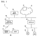
- FIG. 1 is a block diagram illustrating an example of a whole configuration of a device system 1.
- the device system 1 is equipped with a terminal device 10, a wireless access point 20, a device manager 30, a controller 40, field devices 50 and 60, an information processor 70, and a sensor 80.
- the terminal device 10 and the wireless access point 20 are connected through a wireless network N1.
- the wireless access point 20 and the device manager 30 are connected to an intranet N2.
- the wireless network N1 is a wireless network provided in a field of a plant by the wireless access point 20.
- the wireless network N1 is a wireless network which can perform wireless communication in conformity with wireless communication standards, such as Wi-Fi (registered trademark), WiMAX (registered trademark), 3G/LTE (registered trademark), ISA100.11a, WirelessHART (registered trademark), and so on.
- the intranet N2 is a network such as Ethernet (registered trademark) installed in a monitoring room of the plant.
- the plant includes an industrial plant such as a chemical industrial plant, a plant managing and controlling a wellhead (for example, a gas field and an oil field), a plant managing and controlling a generation of electric power (for example, water power, fire power, and nuclear power), a plant managing and controlling a power harvesting (for example, solar power and wind power), a plant managing and controlling water supply and sewerage systems, a dam, and so on.
- an industrial plant such as a chemical industrial plant, a plant managing and controlling a wellhead (for example, a gas field and an oil field), a plant managing and controlling a generation of electric power (for example, water power, fire power, and nuclear power), a plant managing and controlling a power harvesting (for example, solar power and wind power), a plant managing and controlling water supply and sewerage systems, a dam, and so on.
- a plant managing and controlling a wellhead for example, a gas field and an oil field
- a plant managing and controlling a generation of electric power for example, water power, fire power
- the field devices 50 and 60 are such as a sensor device (for example, a flowmeter and a temperature sensor), a valve device (for example, a flow control valve and an on-off valve), an actuator device (for example, a fan and a motor), and other devices installed in the plant.
- the field devices 50 and 60 are devices controlled by the controller 40.
- the controller 40 and the field devices 50 and 60 are connected to each other through a field network N3.
- the field device 50 is shown as a flowmeter, and the field device 60 is shown as a valve device.
- the controller 40 controls an opening/closing operation of the valve device 60 based on flow quantity of fluid flowing in a pipe, which is measured by the flowmeter 50.
- the field devices 50 and 60 may be a vibration sensor which monitors vibration of a pipe and a valve device, or may be a noise sensor which monitors sound emitted from an actuator device.
- the information processor 70 is a cloud server provided in a cloud CL.
- the information processor 70 communicates with the terminal device 10 through the intranet N2, the wireless access point 20, and the wireless network N1.
- the information processor 70 has a function of collecting data from the terminal device 10, a function of storing the collected data, and a function of analyzing the data collected from the terminal device 10.
- the sensor 80 detects a state around the field device installed in the plant.
- the plant worker W checks a field device
- the plant worker W carries the terminal device 10 and the sensor 80 to the place of the field device which is a check target.
- the terminal device 10 and the sensor 80 are connected through a short-distance wireless network N4.
- the short-distance wireless network N4 is a wireless network which is in conformity with wireless communication standards, such as Bluetooth (registered trademark).
- the terminal device 10 is a device used for displaying a check list of field devices which are investigation targets, and is used by the plant worker W.
- the terminal device 10 is a tablet computer, a notebook computer, or a smart phone.
- an arbitrary terminal device which is equipped with functions required for displaying the check list, can be used.
- FIG. 2 is a block diagram illustrating an example of a main configuration of the terminal device and a main configuration of the sensor.
- the sensor 80 includes a plurality of sensors (a visual sensor 81, an auditory sensor 82, a smell sensor 83, and a tactile sensor 84) and a transmission unit 85.
- the visual sensor 81 is a camera which takes an image of the field device.
- the auditory sensor 82 is a microphone which detects a sound around the field device.
- the smell sensor is a sensor which detects smell around the field device.
- the tactile sensor is a sensor which detects a pressure from outside.
- the transmission unit 85 transmits detection results of the visual sensor 81, the auditory sensor 82, the smell sensor 83, and the tactile sensor 84, to the terminal device 10 through the short-range wireless network N4.
- the terminal device 10 is equipped with an input unit 11, a display 12, a collector 13, and a communicator 14.
- the input unit 11 is a touchpad which receives an input from the plant worker W. If the plant worker W checks the field device, the plant worker W instructs to display a check list by using the input unit 11.
- the plant worker W inputs a check item at a time of checking and a determination result representing whether an abnormality exists or not by using the input unit 11.
- the display 12 is a liquid crystal display, an organic EL (Electro Luminescence) display, or the like.
- the display 12 displays a check list of the field devices, an input screen of a check result, an analysis result representing whether an abnormality exists or not, and so on.
- the collector 13 collects a detection result of the sensor 80 through the short-distance wireless network N4 from the sensor 80.
- the communicator 14 has a function of transmitting information to the wireless access point 20, and a function of receiving information from the wireless access point 20.
- the communicator 14 transmits, to the information processor 70, the detection result of the sensor 80 collected by the collector 13.
- FIG. 3 is a block diagram illustrating an example of a main configuration of the device manager.
- the device manager 30 is equipped with an input unit 31, a display 32, a reader/writer 33, a communicator 34, and storage 35.
- the input unit 31 is an input device, such as a keyboard and a mouse.
- the display 32 is a display such as a liquid crystal display.
- the reader/writer 33 writes information into the storage 35, and reads information out of the storage 35.
- the communicator 34 has a function of transmitting information to the intranet N2, and a function of receiving information from the intranet N2.
- the storage 35 stores field device data which represents data of field devices installed in the plant. A type of the field device, a model number of the field device, and an installation position of the field device are included in the field device data.
- FIG. 4 is a block diagram illustrating an example of a main configuration of the controller.
- the controller 40 is equipped with a communicator 41, a reader/writer 42, a collector 43, and storage 44.
- the collector 43 collects process data 45 from the field devices 50 and 60 through the field network N3.
- the process data 45 is data (for example, measurement data, such as pressure, temperature, flow quantity, and so on) obtained by the field device.
- the reader/writer 42 writes the process data 45 collected by the collector 43 into the storage 44.
- the storage 44 stores process data of each of the field devices.
- the communicator 41 transmits the process data 45 to the information processor 70 through the intranet N2.
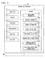
- FIG. 5 is a block diagram illustrating an example of a main configuration of the information processor.
- the information processor 70 is equipped with an input unit 71, a display 72, a collector 73, a reader/writer 74, an analyzer 75, a notifier 76, and storage 77.
- the input unit 71 is an input device, such as a keyboard and a mouse.
- the display 72 is a display such as a liquid crystal display.
- the collector 73 collects the field device data from the device manager 30, and collects the process data from the controller 40.
- the reader/writer 74 writes, into the storage 77, the field device data 36 and the process data 45 which have been collected by the collector 73.
- the analyzer 75 analyzes the detection result of the sensor 80, and determines whether or not an abnormality exists in the field device.
- the notifier 76 notifies the analysis result of the analyzer 75 to the terminal device 10.
- the storage 77 stores check work information 77a, takeover information 77b, danger information 77c, target device data 77d, relational device data 77e, process data 77f of a target device, process data 77g of a relational device, and past check result data (teacher data) 77h.
- the check work information 77a is information, including a check list, a check schedule, a work procedure, and so on.
- the takeover information 77b is information input by the plant worker W when a work is taken over from the plant worker W to another worker.
- the danger information 77c is information which represents a dangerous area in the plant, where the plant worker W cannot enter.
- the target device data 77d is data which represents field device data (such as type and model number) of the field device (target device) which is a check target.
- the relational device data 77e is data which represents field device data (such as type and model number) of the field device (relational device) which is related to the target device.
- relational device is a field device installed within a predetermined distance from the target device, a field device which has a relation of process to the target device (for example, a field device installed in the same pipeline as the target device), and a field device which has a relation of control to the target device (for example, a field device which constitutes a control loop like a flowmeter and a valve which are related). Even if an abnormality has occurred in the target device, the plant worker W checks not only the target device but also the relational device because a fundamental factor of the abnormality may be in the relational device.
- the process data 77f is process data corresponding to the target device, which has been collected from the controller 40.
- the process data 77g is process data corresponding to the relational device, which has been collected from the controller 40.
- the teacher data 77h is data in which past detection results obtained by the sensor 80, an existence/absence of an abnormality in a field device, and field device data (such as type and model number) have been associated with each other.
- the reader/writer 74 of the information processor 70 reads the check work information 77a out of the storage 77.
- the check work information 77a includes a check list which represents a list of field devices to which a check work is conducted.
- the check list includes data for specifying the target device which is a check target, and data for specifying the relational device which is related to the target device.
- the notifier 76 of the information processor 70 notifies the data for specifying the target device to the device manager 30.
- the reader/writer 33 of the device manager 30 reads the field device data 36 of the target device out of the storage 35 based on the data for specifying the target device.
- the communicator 34 of the device manager 30 transmits the field device data 36 of the target device to the information processor 70.
- the collector 73 of the information processor 70 collects the field device data 36 of the target device which has been transmitted from the communicator 34 of the device manager 30.
- the reader/writer 74 of the information processor 70 stores the field device data 36 of the target device, which has been collected by the collector 73, into the storage 77 as the target device data 77d.
- the notifier 76 of the information processor 70 notifies the data for specifying the target device to the controller 40.
- the reader/writer 42 of the controller 40 read the process data 45 of the target device out of the storage 44.
- the communicator 41 of the controller 40 transmits the process data 45 of the target device to the information processor 70.
- the collector 73 of the information processor 70 collects the process data 45 of the target device which has been transmitted from the communicator 41 of the controller 40.
- the reader/writer 74 of the information processor 70 stores the process data 45 of the target device, which has been collected by the collector 73, into the storage 77 as the process data 77f of the target device.
- the notifier 76 of the information processor 70 notifies the data for specifying the relational device to the device manager 30.
- the reader/writer 33 of the device manager 30 reads the field device data 36 of the relational device out of the storage 35 based on the data for specifying the relational device.
- the communicator 34 of the device manager 30 transmits the field device data 36 of the relational device to the information processor 70.
- the collector 73 of the information processor 70 collects the field device data 36 of the relational device which has been transmitted from the communicator 34 of the device manager 30.
- the reader/writer 74 of the information processor 70 stores the field device data 36 of the relational device, which has been collected by the collector 73, into the storage 77 as the relational device data 77e.
- the notifier 76 of the information processor 70 notifies the data for specifying the relational device to the controller 40.
- the reader/writer 42 of the controller 40 reads the process data 45 of the relational device out of the storage 44.
- the communicator 41 of the controller 40 transmits the process data 45 of the relational device to the information processor 70.
- the collector 73 of the information processor 70 collects the process data 45 of the relational device which has been transmitted from the communicator 41 of the controller 40.
- the reader/writer 74 of the information processor 70 stores the process data 45 of the relational device, which has been collected by the collector 73, into the storage 77 as the process data 77g of the relational device.
- the notifier 76 of the information processor 70 transmits, to the terminal device 10, the check work information 77a, the takeover information 77b, and the danger information 77c, which are stored in the storage 77. These sets of information are received by the communicator 14 of the terminal device 10.
- the display 12 of the terminal device 10 displays the check work information 77a, the takeover information 77b, and the danger information 77c, which have been received by the communicator 14.
- the plant worker W confirms that the field device which is a check target is not in a dangerous area with reference to the danger information 77c. Thereafter, the plant worker W starts a check work.
- the plant worker W checks the check work information 77a in order to understand the target device, the relational device, the check schedule, and the work procedure.
- the plant worker W uses the takeover information 77b for the check work.
- the notifier 76 of the information processor 70 transmits, to the terminal device 10, the process data 77f of the target device and the process data 77g of the relational device which are stored in the storage 77. These sets of information are received by the communicator 14 of the terminal device 10.
- the display 12 of the terminal device 10 displays the process data 77f of the target device and the process data 77g of the relational device which have been received by the communicator 14.
- the plant worker W determines whether or not an abnormality has occurred in the field device, by referring to the process data displayed on the display 12 and using five senses. At this time, the visual sensor 81, the auditory sensor 82, the smell sensor 83, and the tactile sensor 84, which are included in the sensor 80, detect a state around the field device.
- FIG. 6 is a drawing illustrating an example of the input screen displayed on the display of the terminal device.
- the display 12 of the terminal device 10 displays check item selection keys (a visual sensor selection key 12a, an auditory sensor selection key 12b, a smell sensor selection key 12c, a tactile sensor selection key 12d, and a process data selection key 12e), a determination result selection keys (an OK selection key 12f, an NG selection key 12g, and an analysis instruction selection key 12h).
- the plant worker W selects at least one of the check item selection keys 12a to 12e, and selects at least one of the determination result selection keys 12f to 12h.
- the plant worker W senses an abnormal sound and an abnormal smell from the field device, the plant worker W selects the auditory sensor selection key 12b and the smell sensor selection key 12c. If the plant worker W determines that an abnormality has not occurred in the field device, the plant worker W selects the OK selection key 12f. If the OK selection key 12f is selected, the communicator 14 of the terminal device 10 transmits, to the information processor 70, a detection result of the sensor 80 about the selected check item and a determination result (OK: normal).
- the plant worker W determines that an abnormality has occurred in the field device, the plant worker W selects the NG selection key 12g. If the NG selection key 12g is selected, the communicator 14 of the terminal device 10 transmits, to the information processor 70, a detection result of the sensor 80 about the selected check item and a determination result (NG: abnormal).
- the collector 73 collects the detection result of the sensor 80 and the determination result, which have been transmitted from the terminal device 10.
- the reader/writer 74 writes, into the storage 77, the detection result of the sensor 80 and the determination result, which have been collected by the collector 73, in association with the target device data 77d or the relational device data 77e (such as type and model number).
- the storage 77 stores the data written by the reader/writer 74 as the teacher data 77h.
- the plant worker W selects the analysis instruction selection key 12h shown in FIG. 6 . If the analysis instruction selection key 12h is selected, the communicator 14 of the terminal device 10 transmits the detection result of the sensor 80 and analysis instructions to the information processor 70.
- FIG. 7 is a drawing illustrating an example of distribution of detection values of the sensor and a determination result about normal or abnormal.
- the horizontal axis represents an auditory sensor value
- the vertical axis represents a smell sensor value.
- the data shown by black circles are past check result data (the teacher data 77h) stored in the storage 77.
- the data displayed here is the teacher data 77h of field devices which are the same model as the field device which is a check target.
- a current detection result 100 of the sensor 80, data group 101 determined as normal in the past, data group 102 determined as abnormal in the past, and a border line 103 between normal and abnormal are shown.
- the analyzer 75 of the information processor 70 performs analysis processing. Specifically, the analyzer 75 reads the teacher data 77h of the field device which is the same model as the field device being checked now out of the storage 77 by using the reader/writer 74 based on the target device data 77d or the relational device data 77e (such as type and model number of the field device). Thereafter, the analyzer 75 calculates the border line 103 between normal (OK) and abnormal (NG) by using a support vector machine based on the teacher data 77h which has been read out of the storage 77.
- the analyzer 75 determines whether or not an abnormality exists in the field device based on the calculated border line 103 and the current detection result 100 of the sensor 80. In a case of the example shown in FIG. 7 , since the current detection result 100 of the sensor 80 is located in an upper right of the border line 103, the analyzer 75 determines that an abnormality has occurred in the field device.
- the notifier 76 notifies, to the terminal device 10, the data representing whether or not an abnormality exists in the field device, which has determined by the analyzer 75.
- the notifier 76 notifies screen data for displaying the analysis result shown in FIG. 7 to the terminal device 10.
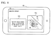
- FIG. 8 is a drawing illustrating an example of an analysis result display screen displayed on the display of the terminal device.
- the display 12 displays a message 12i which represents whether or not an abnormality exists in the field device based on the data representing whether or not an abnormality exists, which has been notified by the notifier 76.
- the display 12 displays an image 12j based on the screen data, which has been notified by the notifier 76.
- the plant worker W can accurately determine whether or not an abnormality has occurred in the field device. If a message which represents that an abnormality exists in the field device is displayed on the display 12, the plant worker W immediately requests exchange or repair of the field device to a manufacturer. Thereby, a safety of the plant is securable.
- FIG. 9 is a flow chart illustrating an example of processing performed by the terminal device.
- the collector 13 of the terminal device 10 collects a detection result from the sensor 80 (Step S10). Thereafter, the display 12 displays the input screen shown in FIG. 6 (Step S11).
- the plant worker W selects at least one of the check item selection keys 12a to 12e, and selects at least one of the determination result selection keys 12f to 12h.
- Step S12 If the OK selection key 12f is selected by the plant worker W (Step S12: YES), the communicator 14 transmits, to the information processor 70, the detection result of the sensor 80 about the check item selected by using the check item selection keys 12a to 12e and the determination result (OK: normal) (Step S13). Thereafter, processing of this flow chart is ended. If the OK selection key 12f is not selected by the plant worker W (Step S12: NO), progressing to Step S14.
- Step S 14 If the NG selection key 12g is selected by the plant worker W (Step S 14: YES), the communicator 14 transmits, to the information processor 70, the detection result of the sensor 80 about the check item selected by using the check item selection keys 12a to 12e and the determination result (NG: abnormal) (Step S15). Thereafter, processing of this flow chart is ended. If the NG selection key 12g is not selected by the plant worker W (Step S14: NO), progressing to Step S16.
- Step S16 if the analysis instruction selection key 12h is selected by the plant worker W (Step S16: YES), the communicator 14 transmits, to the information processor 70, the detection result of the sensor 80 about the check item selected by using the check item selection keys 12a to 12e and the analysis instructions (Step S17), and progressing to Step S18. If the analysis instruction selection key 12h is not selected by the plant worker W (Step S16: NO), returning to Step S12.
- Step S18 if the communicator 14 receives an analysis result from the information processor 70 (Step S18: YES), the display 12 displays the analysis result display screen shown in FIG. 8 (Step S 19), and processing of this flow chart is ended.
- a program for executing the flow chart shown in FIG. 9 may be stored in non-transitory storage medium, such as CD-ROM. If this recording medium is used, for example, the program can be installed in the terminal device 10.
- FIG. 10 is a flow chart illustrating an example of processing performed by the information processor. If the collector 73 of the information processor 70 has received the detection result and the determination result which have been transmitted at Steps S13 and S15 of FIG. 9 (Step S20: YES), the reader/writer 74 writes, into the storage 77, the detection result and the determination result, which have been received by the collector 73, in association with the field device data (the target device data 77d or the relational device data 77e). The storage 77 stores the data written by the reader/writer 74 as the teacher data 77h (Step S21). On the other hand, if the collector 73 has not received the detection result and the determination result which have been transmitted at Step S13 and Step S15 of FIG. 9 (Step S20: NO), progressing to Step S22.
- Step S20 YES
- Step S22 if the collector 73 has received the detection result and the analysis instructions, which have been transmitted at Step S17 of FIG. 9 (Step S22: YES), progressing to Step S23. On the other hand, if the collector 73 has not received the detection result and the analysis instructions, which have been transmitted at Step S17 of FIG. 9 (Step S22: NO), returning to Step S20.
- the analyzer 75 calculates the border line 103 between normal (OK) and abnormal (NG) by using a support vector machine based on the teacher data 77h stored in the storage 77 (Step S23). Thereafter, the analyzer 75 determines whether or not an abnormality exists in the field device based on the calculated border line 103 and the current detection result 100 of the sensor 80 (Step S24).
- the notifier 76 notifies, to the terminal device 10, the data representing whether or not an abnormality exists in the field device, which has been determined by the analyzer 75, and the screen data for displaying the image 12j of FIG. 8 as an analysis result (Step S25). Thereafter, processing of this flow chart is ended.
- a program for executing the flow chart shown in FIG. 10 may be stored in non-transitory storage medium, such as CD-ROM. If this recording medium is used, for example, the program can be installed in the information processor 70.
- the analyzer 75 calculates the border line 103 based on the teacher data 77h of the field device which is the same model as the field device being checked now, but not limited thereto.
- the analyzer 75 may calculate the border line 103 based on the teacher data 77h of the field device of the model similar to the field device being checked now.
- the analyzer 75 may determine whether it is a similar model or not based on the target device data 77d or the relational device data 77e (such as type and model number of the field device).
- the senor 80 may be carried by the plant worker W, the sensor 80 may be installed at a place where the field device is installed.
- the terminal device 10 may be equipped with whole or a part of the sensor 80.
- the analyzer 75 may not determine whether or not an abnormality exists in the field device.
- the predetermined number may be set beforehand by a plant operator by using the input unit 71 of the information processor 70. Thereby, an erroneous determination of the analyzer 75 caused by teacher data of which amount is little can be suppressed.
- the present embodiment can also be used for education for the plant worker W.
- an abnormality determination skill of the plant worker W can be improved by comparing a determination result of the plant worker W with an analysis result of the analyzer 75.
- the device system 1 of the present embodiment is equipped with the terminal device 10 used by the plant worker W, and the information processor 70 connectable to the terminal device 10 through the network.
- the terminal device 10 includes the collector 13 which collects a detection result from the sensor 80 which detects the state around the field device installed in the plant, and the communicator 14 which transmits the detection result collected by the collector 13 to the information processor 70.
- the information processor 70 includes the storage 77 which stores the teacher data 77h in which the past detection results obtained by the sensor 80 and the data whether or not an abnormality exists in the field device are associated with each other, and the analyzer 75 which determines whether or not an abnormality exists in the field device based on the detection result transmitted from the communicator 14 and the teacher data 77h stored in the storage 77.
- the term "configured” is used to describe a component, unit or part of a device includes hardware and/or software that is constructed and/or programmed to carry out the desired function.
- unit is used to describe a component, unit or part of a hardware and/or software that is constructed and/or programmed to carry out the desired function.
- Typical examples of the hardware may include, but are not limited to, a device and a circuit.
Landscapes
- Engineering & Computer Science (AREA)
- Physics & Mathematics (AREA)
- General Physics & Mathematics (AREA)
- Automation & Control Theory (AREA)
- General Engineering & Computer Science (AREA)
- Manufacturing & Machinery (AREA)
- Quality & Reliability (AREA)
- Testing And Monitoring For Control Systems (AREA)
Abstract
Description
- The disclosure relates to a device system, an information processor, a terminal device, and an abnormality determining method.
- Priority is claimed on Japanese Patent Application No.
2015-167776, filed August 27, 2015 - In a plant and a factory (hereinafter, called simply "plant" as a generic name of them), a DCS (Distributed Control System) is established, and an advanced automatic operation is implemented. In the distributed control system, field devices (for example, a measurement device, a manipulation device, a display device, an alarm device, and other devices) and a controller controlling the field devices are connected to each other through a network. Process data which is necessary for a process control are transmitted and received between the controller and the field device.
- Recently, a PAM (Plant Asset Management) system is often installed with the distributed control system so as to increase efficiency of the plant to a maximum level. The plant asset management system performs maintenance of devices and apparatuses installed in the plant, and the plant asset management system maintains and manages the facilities in an appropriate state over a long time. For example, a PRM (Plant Resource Manager) which is an example of the plant asset management system is disclosed in "PRM R3.0 NEW PLANT RESOURCE MANAGER", MATSUMOTO Kouhei et al., Yokogawa Technical Report English Edition, No. 44,2007, pages 5 to 8 (also published in Yokogawa Technical Report, Vol. 51, No. 2, 2007, ).
- If an abnormality occurs in the plant, a plant worker sets a parameter of a field device, adjusts the field device, and checks a state of the field device by using a terminal device. For example, a terminal device used by a plant worker and a field device management tool installed in the terminal device are disclosed in "FieldMate FIELD DEVICE MANAGEMENT TOOL FOR THE NEW ERA", HIROOKA Isao et al., Yokogawa Technical Report English Edition, No. 44,2007, pages 9 to 12 (also published in Yokogawa Technical Report, Vol. 51, No. 2, 2007, ).
- When the plant worker checks the field device, the plant worker determines whether or not an abnormality has occurred in the field device by using five senses. For example, the plant worker senses an abnormal operation sound by using an auditory sense, and senses a leakage of a pipeline by using a visual sense or a smelling sense, in order to determine whether or not an abnormality has occurred in the field device. However, if the worker has a little knowledge and a little experience, the worker may not notice the abnormality which has occurred in the field device.
- A device system may include a terminal device which is usable by a plant worker, and an information processor which is connectable to the terminal device through a network. The terminal device may include a collector configured to collect a detection result from a sensor which detects a state around a device installed in a plant, and a communicator configured to transmit the detection result collected by the collector to the information processor. The information processor may include a storage which stores teacher data in which past detection results obtained by the sensor and data representing whether or not an abnormality exists in the device are associated with each other, and an analyzer configured to determine whether or not an abnormality exists in the device based on the detection result transmitted from the communicator and the teacher data stored in the storage.
- Further features and aspects of the present disclosure will become apparent from the following detailed description of exemplary embodiments with reference to the attached drawings.
-
-
FIG. 1 is a block diagram illustrating an example of a whole configuration of a device system 1. -
FIG. 2 is a block diagram illustrating an example of a main configuration of the terminal device and a main configuration of the sensor. -
FIG. 3 is a block diagram illustrating an example of a main configuration of the device manager. -
FIG. 4 is a block diagram illustrating an example of a main configuration of the controller. -
FIG. 5 is a block diagram illustrating an example of a main configuration of the information processor. -
FIG. 6 is a drawing illustrating an example of the input screen displayed on the display of the terminal device. -
FIG. 7 is a drawing illustrating an example of distribution of detection values of the sensor and a determination result about normal or abnormal. -
FIG. 8 is a drawing illustrating an example of an analysis result display screen displayed on the display of the terminal device. -
FIG. 9 is a flow chart illustrating an example of processing performed by the terminal device. -
FIG. 10 is a flow chart illustrating an example of processing performed by the information processor. - The embodiments of the present invention will be now described herein with reference to illustrative preferred embodiments. Those skilled in the art will recognize that many alternative preferred embodiments can be accomplished using the teaching of the present invention and that the present invention is not limited to the preferred embodiments illustrated herein for explanatory purposes.
- An aspect of the present invention is to provide a device system, an information processor, a terminal device, and an abnormality determining method which can accurately determine whether or not an abnormality has occurred in a field device even if a worker has a little knowledge and a little experience.
- Hereinafter, a device system, an information processor, a terminal device, and an abnormality determining method will be described with reference to drawings.
-
FIG. 1 is a block diagram illustrating an example of a whole configuration of a device system 1. As shown inFIG. 1 , the device system 1 is equipped with aterminal device 10, awireless access point 20, adevice manager 30, acontroller 40,field devices information processor 70, and asensor 80. - The
terminal device 10 and thewireless access point 20 are connected through a wireless network N1. Thewireless access point 20 and thedevice manager 30 are connected to an intranet N2. The wireless network N1 is a wireless network provided in a field of a plant by thewireless access point 20. The wireless network N1 is a wireless network which can perform wireless communication in conformity with wireless communication standards, such as Wi-Fi (registered trademark), WiMAX (registered trademark), 3G/LTE (registered trademark), ISA100.11a, WirelessHART (registered trademark), and so on. The intranet N2 is a network such as Ethernet (registered trademark) installed in a monitoring room of the plant. - The plant includes an industrial plant such as a chemical industrial plant, a plant managing and controlling a wellhead (for example, a gas field and an oil field), a plant managing and controlling a generation of electric power (for example, water power, fire power, and nuclear power), a plant managing and controlling a power harvesting (for example, solar power and wind power), a plant managing and controlling water supply and sewerage systems, a dam, and so on.
- The
field devices field devices controller 40. Thecontroller 40 and thefield devices - In an example of
FIG. 1 , thefield device 50 is shown as a flowmeter, and thefield device 60 is shown as a valve device. Thecontroller 40 controls an opening/closing operation of thevalve device 60 based on flow quantity of fluid flowing in a pipe, which is measured by theflowmeter 50. Thefield devices - The
information processor 70 is a cloud server provided in a cloud CL. Theinformation processor 70 communicates with theterminal device 10 through the intranet N2, thewireless access point 20, and the wireless network N1. Theinformation processor 70 has a function of collecting data from theterminal device 10, a function of storing the collected data, and a function of analyzing the data collected from theterminal device 10. - The
sensor 80 detects a state around the field device installed in the plant. When a plant worker W checks a field device, the plant worker W carries theterminal device 10 and thesensor 80 to the place of the field device which is a check target. Theterminal device 10 and thesensor 80 are connected through a short-distance wireless network N4. The short-distance wireless network N4 is a wireless network which is in conformity with wireless communication standards, such as Bluetooth (registered trademark). - If an abnormality occurs in the plant, the plant worker W investigates a factor of the abnormality. The
terminal device 10 is a device used for displaying a check list of field devices which are investigation targets, and is used by the plant worker W. For example, theterminal device 10 is a tablet computer, a notebook computer, or a smart phone. However, an arbitrary terminal device, which is equipped with functions required for displaying the check list, can be used. -
FIG. 2 is a block diagram illustrating an example of a main configuration of the terminal device and a main configuration of the sensor. As shown inFIG. 2 , thesensor 80 includes a plurality of sensors (avisual sensor 81, anauditory sensor 82, asmell sensor 83, and a tactile sensor 84) and atransmission unit 85. For example, thevisual sensor 81 is a camera which takes an image of the field device. For example, theauditory sensor 82 is a microphone which detects a sound around the field device. For example, the smell sensor is a sensor which detects smell around the field device. For example, the tactile sensor is a sensor which detects a pressure from outside. Thetransmission unit 85 transmits detection results of thevisual sensor 81, theauditory sensor 82, thesmell sensor 83, and thetactile sensor 84, to theterminal device 10 through the short-range wireless network N4. - As shown in
FIG. 2 , theterminal device 10 is equipped with aninput unit 11, adisplay 12, acollector 13, and acommunicator 14. For example, theinput unit 11 is a touchpad which receives an input from the plant worker W. If the plant worker W checks the field device, the plant worker W instructs to display a check list by using theinput unit 11. Although details will be described later, the plant worker W inputs a check item at a time of checking and a determination result representing whether an abnormality exists or not by using theinput unit 11. - For example, the
display 12 is a liquid crystal display, an organic EL (Electro Luminescence) display, or the like. Thedisplay 12 displays a check list of the field devices, an input screen of a check result, an analysis result representing whether an abnormality exists or not, and so on. Thecollector 13 collects a detection result of thesensor 80 through the short-distance wireless network N4 from thesensor 80. - The
communicator 14 has a function of transmitting information to thewireless access point 20, and a function of receiving information from thewireless access point 20. Thecommunicator 14 transmits, to theinformation processor 70, the detection result of thesensor 80 collected by thecollector 13. -
FIG. 3 is a block diagram illustrating an example of a main configuration of the device manager. As shown inFIG. 3 , thedevice manager 30 is equipped with aninput unit 31, adisplay 32, a reader/writer 33, acommunicator 34, andstorage 35. For example, theinput unit 31 is an input device, such as a keyboard and a mouse. For example, thedisplay 32 is a display such as a liquid crystal display. - The reader/
writer 33 writes information into thestorage 35, and reads information out of thestorage 35. Thecommunicator 34 has a function of transmitting information to the intranet N2, and a function of receiving information from the intranet N2. Thestorage 35 stores field device data which represents data of field devices installed in the plant. A type of the field device, a model number of the field device, and an installation position of the field device are included in the field device data. -
FIG. 4 is a block diagram illustrating an example of a main configuration of the controller. As shown inFIG. 4 , thecontroller 40 is equipped with acommunicator 41, a reader/writer 42, acollector 43, andstorage 44. Thecollector 43 collectsprocess data 45 from thefield devices process data 45 is data (for example, measurement data, such as pressure, temperature, flow quantity, and so on) obtained by the field device. The reader/writer 42 writes theprocess data 45 collected by thecollector 43 into thestorage 44. Thestorage 44 stores process data of each of the field devices. Thecommunicator 41 transmits theprocess data 45 to theinformation processor 70 through the intranet N2. -
FIG. 5 is a block diagram illustrating an example of a main configuration of the information processor. As shown inFIG. 5 , theinformation processor 70 is equipped with aninput unit 71, adisplay 72, acollector 73, a reader/writer 74, ananalyzer 75, anotifier 76, andstorage 77. For example, theinput unit 71 is an input device, such as a keyboard and a mouse. For example, thedisplay 72 is a display such as a liquid crystal display. - The
collector 73 collects the field device data from thedevice manager 30, and collects the process data from thecontroller 40. The reader/writer 74 writes, into thestorage 77, thefield device data 36 and theprocess data 45 which have been collected by thecollector 73. Although details will be described later, theanalyzer 75 analyzes the detection result of thesensor 80, and determines whether or not an abnormality exists in the field device. Thenotifier 76 notifies the analysis result of theanalyzer 75 to theterminal device 10. - The
storage 77 stores checkwork information 77a,takeover information 77b,danger information 77c,target device data 77d,relational device data 77e,process data 77f of a target device,process data 77g of a relational device, and past check result data (teacher data) 77h. - The
check work information 77a is information, including a check list, a check schedule, a work procedure, and so on. Thetakeover information 77b is information input by the plant worker W when a work is taken over from the plant worker W to another worker. Thedanger information 77c is information which represents a dangerous area in the plant, where the plant worker W cannot enter. Thetarget device data 77d is data which represents field device data (such as type and model number) of the field device (target device) which is a check target. Therelational device data 77e is data which represents field device data (such as type and model number) of the field device (relational device) which is related to the target device. - For example, relational device is a field device installed within a predetermined distance from the target device, a field device which has a relation of process to the target device (for example, a field device installed in the same pipeline as the target device), and a field device which has a relation of control to the target device (for example, a field device which constitutes a control loop like a flowmeter and a valve which are related). Even if an abnormality has occurred in the target device, the plant worker W checks not only the target device but also the relational device because a fundamental factor of the abnormality may be in the relational device.
- The
process data 77f is process data corresponding to the target device, which has been collected from thecontroller 40. Theprocess data 77g is process data corresponding to the relational device, which has been collected from thecontroller 40. Theteacher data 77h is data in which past detection results obtained by thesensor 80, an existence/absence of an abnormality in a field device, and field device data (such as type and model number) have been associated with each other. - Next, a check work of the field device will be described. The reader/
writer 74 of theinformation processor 70 reads thecheck work information 77a out of thestorage 77. Thecheck work information 77a includes a check list which represents a list of field devices to which a check work is conducted. The check list includes data for specifying the target device which is a check target, and data for specifying the relational device which is related to the target device. - The
notifier 76 of theinformation processor 70 notifies the data for specifying the target device to thedevice manager 30. The reader/writer 33 of thedevice manager 30 reads thefield device data 36 of the target device out of thestorage 35 based on the data for specifying the target device. Thecommunicator 34 of thedevice manager 30 transmits thefield device data 36 of the target device to theinformation processor 70. - The
collector 73 of theinformation processor 70 collects thefield device data 36 of the target device which has been transmitted from thecommunicator 34 of thedevice manager 30. The reader/writer 74 of theinformation processor 70 stores thefield device data 36 of the target device, which has been collected by thecollector 73, into thestorage 77 as thetarget device data 77d. - The
notifier 76 of theinformation processor 70 notifies the data for specifying the target device to thecontroller 40. The reader/writer 42 of thecontroller 40 read theprocess data 45 of the target device out of thestorage 44. Thecommunicator 41 of thecontroller 40 transmits theprocess data 45 of the target device to theinformation processor 70. - The
collector 73 of theinformation processor 70 collects theprocess data 45 of the target device which has been transmitted from thecommunicator 41 of thecontroller 40. The reader/writer 74 of theinformation processor 70 stores theprocess data 45 of the target device, which has been collected by thecollector 73, into thestorage 77 as theprocess data 77f of the target device. - On the other hand, the
notifier 76 of theinformation processor 70 notifies the data for specifying the relational device to thedevice manager 30. The reader/writer 33 of thedevice manager 30 reads thefield device data 36 of the relational device out of thestorage 35 based on the data for specifying the relational device. Thecommunicator 34 of thedevice manager 30 transmits thefield device data 36 of the relational device to theinformation processor 70. - The
collector 73 of theinformation processor 70 collects thefield device data 36 of the relational device which has been transmitted from thecommunicator 34 of thedevice manager 30. The reader/writer 74 of theinformation processor 70 stores thefield device data 36 of the relational device, which has been collected by thecollector 73, into thestorage 77 as therelational device data 77e. - The
notifier 76 of theinformation processor 70 notifies the data for specifying the relational device to thecontroller 40. The reader/writer 42 of thecontroller 40 reads theprocess data 45 of the relational device out of thestorage 44. Thecommunicator 41 of thecontroller 40 transmits theprocess data 45 of the relational device to theinformation processor 70. - The
collector 73 of theinformation processor 70 collects theprocess data 45 of the relational device which has been transmitted from thecommunicator 41 of thecontroller 40. The reader/writer 74 of theinformation processor 70 stores theprocess data 45 of the relational device, which has been collected by thecollector 73, into thestorage 77 as theprocess data 77g of the relational device. - The
notifier 76 of theinformation processor 70 transmits, to theterminal device 10, thecheck work information 77a, thetakeover information 77b, and thedanger information 77c, which are stored in thestorage 77. These sets of information are received by thecommunicator 14 of theterminal device 10. Thedisplay 12 of theterminal device 10 displays thecheck work information 77a, thetakeover information 77b, and thedanger information 77c, which have been received by thecommunicator 14. - The plant worker W confirms that the field device which is a check target is not in a dangerous area with reference to the
danger information 77c. Thereafter, the plant worker W starts a check work. The plant worker W checks thecheck work information 77a in order to understand the target device, the relational device, the check schedule, and the work procedure. The plant worker W uses thetakeover information 77b for the check work. - The
notifier 76 of theinformation processor 70 transmits, to theterminal device 10, theprocess data 77f of the target device and theprocess data 77g of the relational device which are stored in thestorage 77. These sets of information are received by thecommunicator 14 of theterminal device 10. Thedisplay 12 of theterminal device 10 displays theprocess data 77f of the target device and theprocess data 77g of the relational device which have been received by thecommunicator 14. - The plant worker W determines whether or not an abnormality has occurred in the field device, by referring to the process data displayed on the
display 12 and using five senses. At this time, thevisual sensor 81, theauditory sensor 82, thesmell sensor 83, and thetactile sensor 84, which are included in thesensor 80, detect a state around the field device. -
FIG. 6 is a drawing illustrating an example of the input screen displayed on the display of the terminal device. As shown inFIG. 6 , thedisplay 12 of theterminal device 10 displays check item selection keys (a visual sensor selection key 12a, an auditory sensor selection key 12b, a smell sensor selection key 12c, a tactile sensor selection key 12d, and a process data selection key 12e), a determination result selection keys (an OK selection key 12f, anNG selection key 12g, and an analysis instruction selection key 12h). The plant worker W selects at least one of the checkitem selection keys 12a to 12e, and selects at least one of the determinationresult selection keys 12f to 12h. - For example, if the plant worker W senses an abnormal sound and an abnormal smell from the field device, the plant worker W selects the auditory sensor selection key 12b and the smell sensor selection key 12c. If the plant worker W determines that an abnormality has not occurred in the field device, the plant worker W selects the OK selection key 12f. If the OK selection key 12f is selected, the
communicator 14 of theterminal device 10 transmits, to theinformation processor 70, a detection result of thesensor 80 about the selected check item and a determination result (OK: normal). - If the plant worker W determines that an abnormality has occurred in the field device, the plant worker W selects the NG selection key 12g. If the
NG selection key 12g is selected, thecommunicator 14 of theterminal device 10 transmits, to theinformation processor 70, a detection result of thesensor 80 about the selected check item and a determination result (NG: abnormal). - On the other hand, in the
information processor 70, thecollector 73 collects the detection result of thesensor 80 and the determination result, which have been transmitted from theterminal device 10. The reader/writer 74 writes, into thestorage 77, the detection result of thesensor 80 and the determination result, which have been collected by thecollector 73, in association with thetarget device data 77d or therelational device data 77e (such as type and model number). Thestorage 77 stores the data written by the reader/writer 74 as theteacher data 77h. - If the plant worker W cannot determine whether an abnormality exists or not, the plant worker W selects the analysis instruction selection key 12h shown in
FIG. 6 . If the analysis instruction selection key 12h is selected, thecommunicator 14 of theterminal device 10 transmits the detection result of thesensor 80 and analysis instructions to theinformation processor 70. -
FIG. 7 is a drawing illustrating an example of distribution of detection values of the sensor and a determination result about normal or abnormal. InFIG. 7 , the horizontal axis represents an auditory sensor value, and the vertical axis represents a smell sensor value. The data shown by black circles are past check result data (theteacher data 77h) stored in thestorage 77. The data displayed here is theteacher data 77h of field devices which are the same model as the field device which is a check target. InFIG. 7 , acurrent detection result 100 of thesensor 80,data group 101 determined as normal in the past,data group 102 determined as abnormal in the past, and aborder line 103 between normal and abnormal are shown. - If the detection result of the
sensor 80 and the analysis instructions have been received from theterminal device 10, theanalyzer 75 of theinformation processor 70 performs analysis processing. Specifically, theanalyzer 75 reads theteacher data 77h of the field device which is the same model as the field device being checked now out of thestorage 77 by using the reader/writer 74 based on thetarget device data 77d or therelational device data 77e (such as type and model number of the field device). Thereafter, theanalyzer 75 calculates theborder line 103 between normal (OK) and abnormal (NG) by using a support vector machine based on theteacher data 77h which has been read out of thestorage 77. - The
analyzer 75 determines whether or not an abnormality exists in the field device based on thecalculated border line 103 and thecurrent detection result 100 of thesensor 80. In a case of the example shown inFIG. 7 , since thecurrent detection result 100 of thesensor 80 is located in an upper right of theborder line 103, theanalyzer 75 determines that an abnormality has occurred in the field device. - The
notifier 76 notifies, to theterminal device 10, the data representing whether or not an abnormality exists in the field device, which has determined by theanalyzer 75. Thenotifier 76 notifies screen data for displaying the analysis result shown inFIG. 7 to theterminal device 10. -
FIG. 8 is a drawing illustrating an example of an analysis result display screen displayed on the display of the terminal device. As shown inFIG. 8 , thedisplay 12 displays amessage 12i which represents whether or not an abnormality exists in the field device based on the data representing whether or not an abnormality exists, which has been notified by thenotifier 76. Thedisplay 12 displays animage 12j based on the screen data, which has been notified by thenotifier 76. - Thereby, even if the plant worker W has a little knowledge and a little experience, the plant worker W can accurately determine whether or not an abnormality has occurred in the field device. If a message which represents that an abnormality exists in the field device is displayed on the
display 12, the plant worker W immediately requests exchange or repair of the field device to a manufacturer. Thereby, a safety of the plant is securable. -
FIG. 9 is a flow chart illustrating an example of processing performed by the terminal device. Thecollector 13 of theterminal device 10 collects a detection result from the sensor 80 (Step S10). Thereafter, thedisplay 12 displays the input screen shown inFIG. 6 (Step S11). The plant worker W selects at least one of the checkitem selection keys 12a to 12e, and selects at least one of the determinationresult selection keys 12f to 12h. - If the OK selection key 12f is selected by the plant worker W (Step S12: YES), the
communicator 14 transmits, to theinformation processor 70, the detection result of thesensor 80 about the check item selected by using the checkitem selection keys 12a to 12e and the determination result (OK: normal) (Step S13). Thereafter, processing of this flow chart is ended. If the OK selection key 12f is not selected by the plant worker W (Step S12: NO), progressing to Step S14. - If the
NG selection key 12g is selected by the plant worker W (Step S 14: YES), thecommunicator 14 transmits, to theinformation processor 70, the detection result of thesensor 80 about the check item selected by using the checkitem selection keys 12a to 12e and the determination result (NG: abnormal) (Step S15). Thereafter, processing of this flow chart is ended. If theNG selection key 12g is not selected by the plant worker W (Step S14: NO), progressing to Step S16. - In Step S16, if the analysis instruction selection key 12h is selected by the plant worker W (Step S16: YES), the
communicator 14 transmits, to theinformation processor 70, the detection result of thesensor 80 about the check item selected by using the checkitem selection keys 12a to 12e and the analysis instructions (Step S17), and progressing to Step S18. If the analysis instruction selection key 12h is not selected by the plant worker W (Step S16: NO), returning to Step S12. - In Step S18, if the
communicator 14 receives an analysis result from the information processor 70 (Step S18: YES), thedisplay 12 displays the analysis result display screen shown inFIG. 8 (Step S 19), and processing of this flow chart is ended. - For example, a program for executing the flow chart shown in
FIG. 9 may be stored in non-transitory storage medium, such as CD-ROM. If this recording medium is used, for example, the program can be installed in theterminal device 10. -
FIG. 10 is a flow chart illustrating an example of processing performed by the information processor. If thecollector 73 of theinformation processor 70 has received the detection result and the determination result which have been transmitted at Steps S13 and S15 ofFIG. 9 (Step S20: YES), the reader/writer 74 writes, into thestorage 77, the detection result and the determination result, which have been received by thecollector 73, in association with the field device data (thetarget device data 77d or therelational device data 77e). Thestorage 77 stores the data written by the reader/writer 74 as theteacher data 77h (Step S21). On the other hand, if thecollector 73 has not received the detection result and the determination result which have been transmitted at Step S13 and Step S15 ofFIG. 9 (Step S20: NO), progressing to Step S22. - In Step S22, if the
collector 73 has received the detection result and the analysis instructions, which have been transmitted at Step S17 ofFIG. 9 (Step S22: YES), progressing to Step S23. On the other hand, if thecollector 73 has not received the detection result and the analysis instructions, which have been transmitted at Step S17 ofFIG. 9 (Step S22: NO), returning to Step S20. - If the detection result and the analysis instructions have been received in Step S22, as described by using
FIG. 7 , theanalyzer 75 calculates theborder line 103 between normal (OK) and abnormal (NG) by using a support vector machine based on theteacher data 77h stored in the storage 77 (Step S23). Thereafter, theanalyzer 75 determines whether or not an abnormality exists in the field device based on thecalculated border line 103 and thecurrent detection result 100 of the sensor 80 (Step S24). - The
notifier 76 notifies, to theterminal device 10, the data representing whether or not an abnormality exists in the field device, which has been determined by theanalyzer 75, and the screen data for displaying theimage 12j ofFIG. 8 as an analysis result (Step S25). Thereafter, processing of this flow chart is ended. - For example, a program for executing the flow chart shown in
FIG. 10 may be stored in non-transitory storage medium, such as CD-ROM. If this recording medium is used, for example, the program can be installed in theinformation processor 70. - In the present embodiment, although the
analyzer 75 calculates theborder line 103 based on theteacher data 77h of the field device which is the same model as the field device being checked now, but not limited thereto. For example, theanalyzer 75 may calculate theborder line 103 based on theteacher data 77h of the field device of the model similar to the field device being checked now. Theanalyzer 75 may determine whether it is a similar model or not based on thetarget device data 77d or therelational device data 77e (such as type and model number of the field device). - In the present embodiment, although the
sensor 80 is carried by the plant worker W, thesensor 80 may be installed at a place where the field device is installed. Theterminal device 10 may be equipped with whole or a part of thesensor 80. - In the present embodiment, if the
teacher data 77h stored in thestorage 77 is less than a predetermined number, theanalyzer 75 may not determine whether or not an abnormality exists in the field device. The predetermined number may be set beforehand by a plant operator by using theinput unit 71 of theinformation processor 70. Thereby, an erroneous determination of theanalyzer 75 caused by teacher data of which amount is little can be suppressed. - The present embodiment can also be used for education for the plant worker W. For example, an abnormality determination skill of the plant worker W can be improved by comparing a determination result of the plant worker W with an analysis result of the
analyzer 75. - As described above, the device system 1 of the present embodiment is equipped with the
terminal device 10 used by the plant worker W, and theinformation processor 70 connectable to theterminal device 10 through the network. Theterminal device 10 includes thecollector 13 which collects a detection result from thesensor 80 which detects the state around the field device installed in the plant, and thecommunicator 14 which transmits the detection result collected by thecollector 13 to theinformation processor 70. - The
information processor 70 includes thestorage 77 which stores theteacher data 77h in which the past detection results obtained by thesensor 80 and the data whether or not an abnormality exists in the field device are associated with each other, and theanalyzer 75 which determines whether or not an abnormality exists in the field device based on the detection result transmitted from thecommunicator 14 and theteacher data 77h stored in thestorage 77. - Thereby, even if the plant worker has a little knowledge and a little experience, whether or not an abnormality has occurred in the field device can be accurately determined.
- As used herein, the following directional terms "front, back, above, downward, right, left, vertical, horizontal, below, transverse, row and column" as well as any other similar directional terms refer to those instructions of a device equipped with the present invention. Accordingly, these terms, as utilized to describe the present invention should be interpreted relative to a device equipped with the present invention.
- The term "configured" is used to describe a component, unit or part of a device includes hardware and/or software that is constructed and/or programmed to carry out the desired function.
- Moreover, terms that are expressed as "means-plus function" in the claims should include any structure that can be utilized to carry out the function of that part of the present invention.
- The term "unit" is used to describe a component, unit or part of a hardware and/or software that is constructed and/or programmed to carry out the desired function. Typical examples of the hardware may include, but are not limited to, a device and a circuit.
- While preferred embodiments of the present invention have been described and illustrated above, it should be understood that these are examples of the present invention and are not to be considered as limiting. Additions, omissions, substitutions, and other modifications can be made without departing from the scope of the present invention. Accordingly, the present invention is not to be considered as being limited by the foregoing description, and is only limited by the scope of the claims.
Claims (15)
- A device system comprising:a terminal device which is usable by a plant worker; andan information processor which is connectable to the terminal device through a network,wherein the terminal device comprises:a collector configured to collect a detection result from a sensor which detects a state around a device installed in a plant; anda communicator configured to transmit the detection result collected by the collector to the information processor,wherein the information processor comprises:a storage which stores teacher data in which past detection results obtained by the sensor and data representing whether or not an abnormality exists in the device are associated with each other; andan analyzer configured to determine whether or not an abnormality exists in the device based on the detection result transmitted from the communicator and the teacher data stored in the storage.
- The device system according to claim 1,
wherein the information processor further comprises:a notifier configured to notify data representing whether or not an abnormality exists in the device, which has been determined by the analyzer, to the terminal device. - The device system according to claim 2,
wherein the terminal device further comprises:a display configured to display a message representing whether or not an abnormality exists in the device based on the data notified by the notifier. - The device system according to claim 3,
wherein the sensor comprises a plurality of sensors,
wherein the communicator is configured to receive process data obtained by the device, and
wherein the display is configured to display a check item selector for allowing the plant worker to select at least one check item of the plurality of sensors and the process data, and configured to display a determination result selector for allowing the plant worker to select a determination result representing whether or not an abnormality exists in the device. - The device system according to claim 4,
wherein the communicator is configured to transmit, to the information processor, the detection result of the sensor about the check item selected by using the check item selector and the determination result selected by using the determination result selector,
wherein the storage stores the detection result and the determination result, which have been transmitted from the communicator, in association with each other as the teacher data. - The device system according to any one of claims 3 to 5,
wherein the display is configured to display an analysis instruction selector for instructing, to the analyzer, a determination whether or not an abnormality exists in the device,
wherein the communicator is configured to transmit, to the information processor, the detection result of the sensor and analysis instructions in accordance with a selection of the analysis instruction selector, and
wherein the analyzer is configured to calculate a border line between normal and abnormal of the device based on the teacher data stored in the storage in accordance with the analysis instructions transmitted from the communicator, and configured to determine whether or not an abnormality exists in the device based on the calculated border line and the detection result transmitted from the communicator. - The device system according to any one of claims 1 to 6,
wherein the analyzer is configured not to determine whether or not an abnormality exists in the device if the teacher data stored in the storage is less than a predetermined number. - An information processor comprising:a collector configured to collect a detection result of a sensor which detects a state around a device installed in a plant;a storage which stores teacher data in which past detection results obtained by the sensor and data representing whether or not an abnormality exists in the device are associated with each other; andan analyzer configured to determine whether or not an abnormality exists in the device based on the detection result collected by the collector and the teacher data stored in the storage.
- The information processor according to claim 8, further comprising:a notifier configured to notify data representing whether or not an abnormality exists in the device, which has been determined by the analyzer, to a terminal device.
- The information processor according to claim 9,
wherein the analyzer is configured to receive analysis instructions from the terminal device, configured to calculate a border line between normal and abnormal of the device based on the teacher data stored in the storage in accordance with the received analysis instructions, and configured to determine whether or not an abnormality exists in the device based on the calculated border line and the detection result collected by the collector. - The information processor according to claim 8,
wherein the analyzer is configured not to determine whether or not an abnormality exists in the device if the teacher data stored in the storage is less than a predetermined number. - A terminal device comprising:a collector configured to collect a detection result from a plurality of sensors which detect a state around a device installed in a plant;a communicator configured to receive process data obtained by the device; anda display configured to display a check item selector for allowing a plant worker to select at least one check item of the plurality of sensors and process data, and configured to display a determination result selector for allowing the plant worker to select a determination result representing whether or not an abnormality exists in the device.
- The terminal device according to claim 12,
wherein the communicator is configured to transmit the detection result of the sensor about the check item selected by using the check item selector and the determination result selected by using the determination result selector. - The terminal device according to claim 13,
wherein the display is configured to display an analysis instruction selector for instructing, to an information processor, a determination whether or not an abnormality exists in the device,
wherein the communicator is configured to transmit, to the information processor, the detection result of the sensor and analysis instructions in accordance with a selection of the analysis instruction selector. - An abnormality determining method comprising:collecting a detection result from a sensor which detects a state around a device installed in a plant;reading, out of a storage, teacher data in which past detection results obtained by the sensor and data representing whether or not an abnormality exists in the device are associated with each other; anddetermining whether or not an abnormality exists in the device based on the collected detection result and the teacher data read out of the storage.
Applications Claiming Priority (1)
| Application Number | Priority Date | Filing Date | Title |
|---|---|---|---|
| JP2015167776A JP6288008B2 (en) | 2015-08-27 | 2015-08-27 | Device system, information processing apparatus, terminal device, and abnormality determination method |
Publications (2)
| Publication Number | Publication Date |
|---|---|
| EP3136194A1 true EP3136194A1 (en) | 2017-03-01 |
| EP3136194B1 EP3136194B1 (en) | 2020-02-19 |
Family
ID=57178199
Family Applications (1)
| Application Number | Title | Priority Date | Filing Date |
|---|---|---|---|
| EP16185187.8A Active EP3136194B1 (en) | 2015-08-27 | 2016-08-22 | Device system, information processor, terminal device, and abnormality determining method |
Country Status (3)
| Country | Link |
|---|---|
| US (1) | US10514682B2 (en) |
| EP (1) | EP3136194B1 (en) |
| JP (1) | JP6288008B2 (en) |
Families Citing this family (1)
| Publication number | Priority date | Publication date | Assignee | Title |
|---|---|---|---|---|
| JP7601543B2 (en) * | 2019-01-25 | 2024-12-17 | 住友重機械エンバイロメント株式会社 | Surveillance equipment |
Citations (5)
| Publication number | Priority date | Publication date | Assignee | Title |
|---|---|---|---|---|
| US20110202312A1 (en) * | 2010-02-16 | 2011-08-18 | Katsuhiro Sumi | Operation sound collection system and method |
| US20130073228A1 (en) * | 2011-06-23 | 2013-03-21 | Virtjoule, Inc. | System Responsive to Machine Vibrations and Method of Use |
| US20140156032A1 (en) * | 2012-11-30 | 2014-06-05 | John Jenkins | Equipment sound monitoring system and method |
| WO2014127803A1 (en) * | 2013-02-19 | 2014-08-28 | Abb Technology Ltd | Health determination of process control objects using audio |
| US8949668B2 (en) * | 2011-05-23 | 2015-02-03 | The Boeing Company | Methods and systems for use in identifying abnormal behavior in a control system including independent comparisons to user policies and an event correlation model |
Family Cites Families (12)
| Publication number | Priority date | Publication date | Assignee | Title |
|---|---|---|---|---|
| JP2002049419A (en) * | 2000-08-02 | 2002-02-15 | Yamatake Sangyo Systems Co Ltd | Facility management supporting system |
| US7389204B2 (en) * | 2001-03-01 | 2008-06-17 | Fisher-Rosemount Systems, Inc. | Data presentation system for abnormal situation prevention in a process plant |
| JP2002287818A (en) * | 2001-03-26 | 2002-10-04 | Osaka Gas Co Ltd | Power generation system and monitoring facility |
| US7117119B2 (en) * | 2003-08-01 | 2006-10-03 | Invensys Systems, Inc | System and method for continuous online safety and reliability monitoring |
| JP4265982B2 (en) * | 2004-02-25 | 2009-05-20 | 三菱電機株式会社 | Equipment diagnostic equipment, refrigeration cycle equipment, refrigeration cycle monitoring system |
| US7079984B2 (en) * | 2004-03-03 | 2006-07-18 | Fisher-Rosemount Systems, Inc. | Abnormal situation prevention in a process plant |
| JP2006323538A (en) * | 2005-05-17 | 2006-11-30 | Yokogawa Electric Corp | Anomaly monitoring system and anomaly monitoring method |
| JP4961417B2 (en) * | 2008-12-17 | 2012-06-27 | 株式会社テイエルブイ | Device status information collection method and device status information collection kit used therefor |
| JP5585350B2 (en) * | 2010-09-29 | 2014-09-10 | 横河電機株式会社 | Patrol inspection system |
| JP5689333B2 (en) * | 2011-02-15 | 2015-03-25 | インターナショナル・ビジネス・マシーンズ・コーポレーションInternational Business Machines Corporation | Abnormality detection system, abnormality detection device, abnormality detection method, program, and recording medium |
| JP6099989B2 (en) * | 2013-01-21 | 2017-03-22 | 株式会社日立製作所 | Inspection support processing server and inspection support system |
| US11112925B2 (en) * | 2013-03-15 | 2021-09-07 | Fisher-Rosemount Systems, Inc. | Supervisor engine for process control |
-
2015
- 2015-08-27 JP JP2015167776A patent/JP6288008B2/en not_active Expired - Fee Related
-
2016
- 2016-08-16 US US15/237,875 patent/US10514682B2/en active Active
- 2016-08-22 EP EP16185187.8A patent/EP3136194B1/en active Active
Patent Citations (5)
| Publication number | Priority date | Publication date | Assignee | Title |
|---|---|---|---|---|
| US20110202312A1 (en) * | 2010-02-16 | 2011-08-18 | Katsuhiro Sumi | Operation sound collection system and method |
| US8949668B2 (en) * | 2011-05-23 | 2015-02-03 | The Boeing Company | Methods and systems for use in identifying abnormal behavior in a control system including independent comparisons to user policies and an event correlation model |
| US20130073228A1 (en) * | 2011-06-23 | 2013-03-21 | Virtjoule, Inc. | System Responsive to Machine Vibrations and Method of Use |
| US20140156032A1 (en) * | 2012-11-30 | 2014-06-05 | John Jenkins | Equipment sound monitoring system and method |
| WO2014127803A1 (en) * | 2013-02-19 | 2014-08-28 | Abb Technology Ltd | Health determination of process control objects using audio |
Non-Patent Citations (4)
| Title |
|---|
| HIROOKA ISAO ET AL.: "FieldMate FIELD DEVICE MANAGEMENT TOOL FOR THE NEW ERA", YOKOGAWA TECHNICAL REPORT ENGLISH EDITION, 2007, pages 9 - 12, XP002565596 |
| MATSUMOTO KOUHEI ET AL.: "PRM R3.0 NEW PLANT RESOURCE MANAGER", YOKOGAWA TECHNICAL REPORT ENGLISH EDITION, vol. 44, 2007, pages 5 - 8 |
| YOKOGAWA TECHNICAL REPORT, vol. 51, no. 2, 2007, pages 41 - 44 |
| YOKOGAWA TECHNICAL REPORT, vol. 51, no. 2, 2007, pages 45 - 48 |
Also Published As
| Publication number | Publication date |
|---|---|
| US10514682B2 (en) | 2019-12-24 |
| JP6288008B2 (en) | 2018-03-07 |
| JP2017045307A (en) | 2017-03-02 |
| EP3136194B1 (en) | 2020-02-19 |
| US20170060122A1 (en) | 2017-03-02 |
Similar Documents
| Publication | Publication Date | Title |
|---|---|---|
| US10395222B2 (en) | Information display method, information display apparatus, information display system, and non-transitory computer readable storage medium | |
| JP7648818B2 (en) | SYSTEM AND METHOD FOR MANAGING ALERTS ASSOCIATED WITH DEVICES OF A PROCESS CONTROL SYSTEM - Patent application | |
| US10419526B2 (en) | Plant control system, controller, manager, and plant information processing method | |
| US20170131705A1 (en) | Field device, field device system, and diagnostic method | |
| US20160291577A1 (en) | Work support device and work support method | |
| US20240385070A1 (en) | Water leak detection device and integration platform | |
| EP3657413A1 (en) | Information collection system, information collection termal device, information collection server, and information collection method | |
| KR20200121134A (en) | Remote monitoring system for safety of gas and remote monitoring apparatus for safety of gas | |
| EP3136194B1 (en) | Device system, information processor, terminal device, and abnormality determining method | |
| JP6471878B2 (en) | PLANT OPERATION SUPPORT SYSTEM, INFORMATION PROCESSING DEVICE, MOBILE TERMINAL DEVICE, AND DISPLAY METHOD | |
| EP3139234B1 (en) | Device system, information processing device, and operation proposal method | |
| AU2018427120A1 (en) | Real-time operations information on wearable smart heads up display | |
| EP2757803B1 (en) | Field device and communication system | |
| CN117847436A (en) | Intelligent pipeline monitoring and maintenance system | |
| US10210305B2 (en) | Device system, information processor, terminal device, and displaying method | |
| KR101740666B1 (en) | Method for operating cyber security evaluation managemental system | |
| KR102872342B1 (en) | Smart leak management sysrem | |
| CN120218640A (en) | Method, device, medium, electronic equipment and product for determining operation plan | |
| CN120612073A (en) | Real estate operation and maintenance management method, device, equipment and medium based on digital twin |
Legal Events
| Date | Code | Title | Description |
|---|---|---|---|
| PUAI | Public reference made under article 153(3) epc to a published international application that has entered the european phase |
Free format text: ORIGINAL CODE: 0009012 |
|
| STAA | Information on the status of an ep patent application or granted ep patent |
Free format text: STATUS: THE APPLICATION HAS BEEN PUBLISHED |
|
| AK | Designated contracting states |
Kind code of ref document: A1 Designated state(s): AL AT BE BG CH CY CZ DE DK EE ES FI FR GB GR HR HU IE IS IT LI LT LU LV MC MK MT NL NO PL PT RO RS SE SI SK SM TR |
|
| AX | Request for extension of the european patent |
Extension state: BA ME |
|
| STAA | Information on the status of an ep patent application or granted ep patent |
Free format text: STATUS: REQUEST FOR EXAMINATION WAS MADE |
|
| 17P | Request for examination filed |
Effective date: 20170824 |
|
| RBV | Designated contracting states (corrected) |
Designated state(s): AL AT BE BG CH CY CZ DE DK EE ES FI FR GB GR HR HU IE IS IT LI LT LU LV MC MK MT NL NO PL PT RO RS SE SI SK SM TR |
|
| GRAP | Despatch of communication of intention to grant a patent |
Free format text: ORIGINAL CODE: EPIDOSNIGR1 |
|
| STAA | Information on the status of an ep patent application or granted ep patent |
Free format text: STATUS: GRANT OF PATENT IS INTENDED |
|
| INTG | Intention to grant announced |
Effective date: 20190926 |
|
| GRAS | Grant fee paid |
Free format text: ORIGINAL CODE: EPIDOSNIGR3 |
|
| GRAA | (expected) grant |
Free format text: ORIGINAL CODE: 0009210 |
|
| STAA | Information on the status of an ep patent application or granted ep patent |
Free format text: STATUS: THE PATENT HAS BEEN GRANTED |
|
| AK | Designated contracting states |
Kind code of ref document: B1 Designated state(s): AL AT BE BG CH CY CZ DE DK EE ES FI FR GB GR HR HU IE IS IT LI LT LU LV MC MK MT NL NO PL PT RO RS SE SI SK SM TR |
|
| REG | Reference to a national code |
Ref country code: CH Ref legal event code: EP |
|
| REG | Reference to a national code |
Ref country code: DE Ref legal event code: R096 Ref document number: 602016029943 Country of ref document: DE |
|
| REG | Reference to a national code |
Ref country code: AT Ref legal event code: REF Ref document number: 1235668 Country of ref document: AT Kind code of ref document: T Effective date: 20200315 |
|
| REG | Reference to a national code |
Ref country code: IE Ref legal event code: FG4D |
|
| REG | Reference to a national code |
Ref country code: NL Ref legal event code: FP |
|
| PG25 | Lapsed in a contracting state [announced via postgrant information from national office to epo] |
Ref country code: RS Free format text: LAPSE BECAUSE OF FAILURE TO SUBMIT A TRANSLATION OF THE DESCRIPTION OR TO PAY THE FEE WITHIN THE PRESCRIBED TIME-LIMIT Effective date: 20200219 Ref country code: NO Free format text: LAPSE BECAUSE OF FAILURE TO SUBMIT A TRANSLATION OF THE DESCRIPTION OR TO PAY THE FEE WITHIN THE PRESCRIBED TIME-LIMIT Effective date: 20200519 Ref country code: FI Free format text: LAPSE BECAUSE OF FAILURE TO SUBMIT A TRANSLATION OF THE DESCRIPTION OR TO PAY THE FEE WITHIN THE PRESCRIBED TIME-LIMIT Effective date: 20200219 |
|
| REG | Reference to a national code |
Ref country code: LT Ref legal event code: MG4D |
|
| PG25 | Lapsed in a contracting state [announced via postgrant information from national office to epo] |
Ref country code: GR Free format text: LAPSE BECAUSE OF FAILURE TO SUBMIT A TRANSLATION OF THE DESCRIPTION OR TO PAY THE FEE WITHIN THE PRESCRIBED TIME-LIMIT Effective date: 20200520 Ref country code: LV Free format text: LAPSE BECAUSE OF FAILURE TO SUBMIT A TRANSLATION OF THE DESCRIPTION OR TO PAY THE FEE WITHIN THE PRESCRIBED TIME-LIMIT Effective date: 20200219 Ref country code: BG Free format text: LAPSE BECAUSE OF FAILURE TO SUBMIT A TRANSLATION OF THE DESCRIPTION OR TO PAY THE FEE WITHIN THE PRESCRIBED TIME-LIMIT Effective date: 20200519 Ref country code: IS Free format text: LAPSE BECAUSE OF FAILURE TO SUBMIT A TRANSLATION OF THE DESCRIPTION OR TO PAY THE FEE WITHIN THE PRESCRIBED TIME-LIMIT Effective date: 20200619 Ref country code: SE Free format text: LAPSE BECAUSE OF FAILURE TO SUBMIT A TRANSLATION OF THE DESCRIPTION OR TO PAY THE FEE WITHIN THE PRESCRIBED TIME-LIMIT Effective date: 20200219 Ref country code: HR Free format text: LAPSE BECAUSE OF FAILURE TO SUBMIT A TRANSLATION OF THE DESCRIPTION OR TO PAY THE FEE WITHIN THE PRESCRIBED TIME-LIMIT Effective date: 20200219 |
|
| PG25 | Lapsed in a contracting state [announced via postgrant information from national office to epo] |
Ref country code: LT Free format text: LAPSE BECAUSE OF FAILURE TO SUBMIT A TRANSLATION OF THE DESCRIPTION OR TO PAY THE FEE WITHIN THE PRESCRIBED TIME-LIMIT Effective date: 20200219 Ref country code: DK Free format text: LAPSE BECAUSE OF FAILURE TO SUBMIT A TRANSLATION OF THE DESCRIPTION OR TO PAY THE FEE WITHIN THE PRESCRIBED TIME-LIMIT Effective date: 20200219 Ref country code: SK Free format text: LAPSE BECAUSE OF FAILURE TO SUBMIT A TRANSLATION OF THE DESCRIPTION OR TO PAY THE FEE WITHIN THE PRESCRIBED TIME-LIMIT Effective date: 20200219 Ref country code: ES Free format text: LAPSE BECAUSE OF FAILURE TO SUBMIT A TRANSLATION OF THE DESCRIPTION OR TO PAY THE FEE WITHIN THE PRESCRIBED TIME-LIMIT Effective date: 20200219 Ref country code: RO Free format text: LAPSE BECAUSE OF FAILURE TO SUBMIT A TRANSLATION OF THE DESCRIPTION OR TO PAY THE FEE WITHIN THE PRESCRIBED TIME-LIMIT Effective date: 20200219 Ref country code: CZ Free format text: LAPSE BECAUSE OF FAILURE TO SUBMIT A TRANSLATION OF THE DESCRIPTION OR TO PAY THE FEE WITHIN THE PRESCRIBED TIME-LIMIT Effective date: 20200219 Ref country code: PT Free format text: LAPSE BECAUSE OF FAILURE TO SUBMIT A TRANSLATION OF THE DESCRIPTION OR TO PAY THE FEE WITHIN THE PRESCRIBED TIME-LIMIT Effective date: 20200712 Ref country code: EE Free format text: LAPSE BECAUSE OF FAILURE TO SUBMIT A TRANSLATION OF THE DESCRIPTION OR TO PAY THE FEE WITHIN THE PRESCRIBED TIME-LIMIT Effective date: 20200219 Ref country code: SM Free format text: LAPSE BECAUSE OF FAILURE TO SUBMIT A TRANSLATION OF THE DESCRIPTION OR TO PAY THE FEE WITHIN THE PRESCRIBED TIME-LIMIT Effective date: 20200219 |
|
| REG | Reference to a national code |
Ref country code: AT Ref legal event code: MK05 Ref document number: 1235668 Country of ref document: AT Kind code of ref document: T Effective date: 20200219 |
|
| REG | Reference to a national code |
Ref country code: DE Ref legal event code: R097 Ref document number: 602016029943 Country of ref document: DE |
|
| PLBE | No opposition filed within time limit |
Free format text: ORIGINAL CODE: 0009261 |
|
| STAA | Information on the status of an ep patent application or granted ep patent |
Free format text: STATUS: NO OPPOSITION FILED WITHIN TIME LIMIT |
|
| 26N | No opposition filed |
Effective date: 20201120 |
|
| PG25 | Lapsed in a contracting state [announced via postgrant information from national office to epo] |
Ref country code: AT Free format text: LAPSE BECAUSE OF FAILURE TO SUBMIT A TRANSLATION OF THE DESCRIPTION OR TO PAY THE FEE WITHIN THE PRESCRIBED TIME-LIMIT Effective date: 20200219 Ref country code: IT Free format text: LAPSE BECAUSE OF FAILURE TO SUBMIT A TRANSLATION OF THE DESCRIPTION OR TO PAY THE FEE WITHIN THE PRESCRIBED TIME-LIMIT Effective date: 20200219 |
|
| PG25 | Lapsed in a contracting state [announced via postgrant information from national office to epo] |
Ref country code: SI Free format text: LAPSE BECAUSE OF FAILURE TO SUBMIT A TRANSLATION OF THE DESCRIPTION OR TO PAY THE FEE WITHIN THE PRESCRIBED TIME-LIMIT Effective date: 20200219 Ref country code: PL Free format text: LAPSE BECAUSE OF FAILURE TO SUBMIT A TRANSLATION OF THE DESCRIPTION OR TO PAY THE FEE WITHIN THE PRESCRIBED TIME-LIMIT Effective date: 20200219 |
|
| PG25 | Lapsed in a contracting state [announced via postgrant information from national office to epo] |
Ref country code: MC Free format text: LAPSE BECAUSE OF FAILURE TO SUBMIT A TRANSLATION OF THE DESCRIPTION OR TO PAY THE FEE WITHIN THE PRESCRIBED TIME-LIMIT Effective date: 20200219 |
|
| REG | Reference to a national code |
Ref country code: CH Ref legal event code: PL |
|
| PG25 | Lapsed in a contracting state [announced via postgrant information from national office to epo] |
Ref country code: LI Free format text: LAPSE BECAUSE OF NON-PAYMENT OF DUE FEES Effective date: 20200831 Ref country code: LU Free format text: LAPSE BECAUSE OF NON-PAYMENT OF DUE FEES Effective date: 20200822 Ref country code: CH Free format text: LAPSE BECAUSE OF NON-PAYMENT OF DUE FEES Effective date: 20200831 |
|
| REG | Reference to a national code |
Ref country code: BE Ref legal event code: MM Effective date: 20200831 |
|
| PG25 | Lapsed in a contracting state [announced via postgrant information from national office to epo] |
Ref country code: IE Free format text: LAPSE BECAUSE OF NON-PAYMENT OF DUE FEES Effective date: 20200822 Ref country code: BE Free format text: LAPSE BECAUSE OF NON-PAYMENT OF DUE FEES Effective date: 20200831 |
|
| PG25 | Lapsed in a contracting state [announced via postgrant information from national office to epo] |
Ref country code: TR Free format text: LAPSE BECAUSE OF FAILURE TO SUBMIT A TRANSLATION OF THE DESCRIPTION OR TO PAY THE FEE WITHIN THE PRESCRIBED TIME-LIMIT Effective date: 20200219 Ref country code: MT Free format text: LAPSE BECAUSE OF FAILURE TO SUBMIT A TRANSLATION OF THE DESCRIPTION OR TO PAY THE FEE WITHIN THE PRESCRIBED TIME-LIMIT Effective date: 20200219 Ref country code: CY Free format text: LAPSE BECAUSE OF FAILURE TO SUBMIT A TRANSLATION OF THE DESCRIPTION OR TO PAY THE FEE WITHIN THE PRESCRIBED TIME-LIMIT Effective date: 20200219 |
|
| PG25 | Lapsed in a contracting state [announced via postgrant information from national office to epo] |
Ref country code: MK Free format text: LAPSE BECAUSE OF FAILURE TO SUBMIT A TRANSLATION OF THE DESCRIPTION OR TO PAY THE FEE WITHIN THE PRESCRIBED TIME-LIMIT Effective date: 20200219 Ref country code: AL Free format text: LAPSE BECAUSE OF FAILURE TO SUBMIT A TRANSLATION OF THE DESCRIPTION OR TO PAY THE FEE WITHIN THE PRESCRIBED TIME-LIMIT Effective date: 20200219 |
|
| P01 | Opt-out of the competence of the unified patent court (upc) registered |
Effective date: 20230603 |
|
| PGFP | Annual fee paid to national office [announced via postgrant information from national office to epo] |
Ref country code: NL Payment date: 20250723 Year of fee payment: 10 |
|
| PGFP | Annual fee paid to national office [announced via postgrant information from national office to epo] |
Ref country code: DE Payment date: 20250724 Year of fee payment: 10 |
|
| PGFP | Annual fee paid to national office [announced via postgrant information from national office to epo] |
Ref country code: GB Payment date: 20250724 Year of fee payment: 10 |
|
| PGFP | Annual fee paid to national office [announced via postgrant information from national office to epo] |
Ref country code: FR Payment date: 20250723 Year of fee payment: 10 |