EP3136145A1 - Multicore/multimode fiber joining device - Google Patents
Multicore/multimode fiber joining device Download PDFInfo
- Publication number
- EP3136145A1 EP3136145A1 EP15782719.7A EP15782719A EP3136145A1 EP 3136145 A1 EP3136145 A1 EP 3136145A1 EP 15782719 A EP15782719 A EP 15782719A EP 3136145 A1 EP3136145 A1 EP 3136145A1
- Authority
- EP
- European Patent Office
- Prior art keywords
- group
- mode
- fiber
- light beams
- core
- Prior art date
- Legal status (The legal status is an assumption and is not a legal conclusion. Google has not performed a legal analysis and makes no representation as to the accuracy of the status listed.)
- Granted
Links
Images


Classifications
-
- G—PHYSICS
- G02—OPTICS
- G02B—OPTICAL ELEMENTS, SYSTEMS OR APPARATUS
- G02B6/00—Light guides; Structural details of arrangements comprising light guides and other optical elements, e.g. couplings
- G02B6/10—Light guides; Structural details of arrangements comprising light guides and other optical elements, e.g. couplings of the optical waveguide type
- G02B6/14—Mode converters
-
- G—PHYSICS
- G02—OPTICS
- G02B—OPTICAL ELEMENTS, SYSTEMS OR APPARATUS
- G02B6/00—Light guides; Structural details of arrangements comprising light guides and other optical elements, e.g. couplings
- G02B6/24—Coupling light guides
- G02B6/26—Optical coupling means
- G02B6/27—Optical coupling means with polarisation selective and adjusting means
-
- G—PHYSICS
- G02—OPTICS
- G02B—OPTICAL ELEMENTS, SYSTEMS OR APPARATUS
- G02B6/00—Light guides; Structural details of arrangements comprising light guides and other optical elements, e.g. couplings
- G02B6/24—Coupling light guides
- G02B6/26—Optical coupling means
-
- G—PHYSICS
- G02—OPTICS
- G02B—OPTICAL ELEMENTS, SYSTEMS OR APPARATUS
- G02B6/00—Light guides; Structural details of arrangements comprising light guides and other optical elements, e.g. couplings
- G02B6/24—Coupling light guides
- G02B6/26—Optical coupling means
- G02B6/28—Optical coupling means having data bus means, i.e. plural waveguides interconnected and providing an inherently bidirectional system by mixing and splitting signals
- G02B6/2804—Optical coupling means having data bus means, i.e. plural waveguides interconnected and providing an inherently bidirectional system by mixing and splitting signals forming multipart couplers without wavelength selective elements, e.g. "T" couplers, star couplers
- G02B6/2808—Optical coupling means having data bus means, i.e. plural waveguides interconnected and providing an inherently bidirectional system by mixing and splitting signals forming multipart couplers without wavelength selective elements, e.g. "T" couplers, star couplers using a mixing element which evenly distributes an input signal over a number of outputs
-
- G—PHYSICS
- G02—OPTICS
- G02B—OPTICAL ELEMENTS, SYSTEMS OR APPARATUS
- G02B6/00—Light guides; Structural details of arrangements comprising light guides and other optical elements, e.g. couplings
- G02B6/24—Coupling light guides
- G02B6/26—Optical coupling means
- G02B6/28—Optical coupling means having data bus means, i.e. plural waveguides interconnected and providing an inherently bidirectional system by mixing and splitting signals
- G02B6/2804—Optical coupling means having data bus means, i.e. plural waveguides interconnected and providing an inherently bidirectional system by mixing and splitting signals forming multipart couplers without wavelength selective elements, e.g. "T" couplers, star couplers
- G02B6/2817—Optical coupling means having data bus means, i.e. plural waveguides interconnected and providing an inherently bidirectional system by mixing and splitting signals forming multipart couplers without wavelength selective elements, e.g. "T" couplers, star couplers using reflective elements to split or combine optical signals
-
- G—PHYSICS
- G02—OPTICS
- G02B—OPTICAL ELEMENTS, SYSTEMS OR APPARATUS
- G02B6/00—Light guides; Structural details of arrangements comprising light guides and other optical elements, e.g. couplings
- G02B6/24—Coupling light guides
- G02B6/26—Optical coupling means
- G02B6/32—Optical coupling means having lens focusing means positioned between opposed fibre ends
-
- H—ELECTRICITY
- H04—ELECTRIC COMMUNICATION TECHNIQUE
- H04B—TRANSMISSION
- H04B10/00—Transmission systems employing electromagnetic waves other than radio-waves, e.g. infrared, visible or ultraviolet light, or employing corpuscular radiation, e.g. quantum communication
- H04B10/25—Arrangements specific to fibre transmission
- H04B10/2581—Multimode transmission
-
- H—ELECTRICITY
- H04—ELECTRIC COMMUNICATION TECHNIQUE
- H04J—MULTIPLEX COMMUNICATION
- H04J14/00—Optical multiplex systems
- H04J14/04—Mode multiplex systems
-
- H—ELECTRICITY
- H04—ELECTRIC COMMUNICATION TECHNIQUE
- H04J—MULTIPLEX COMMUNICATION
- H04J14/00—Optical multiplex systems
- H04J14/05—Spatial multiplexing systems
- H04J14/052—Spatial multiplexing systems using multicore fibre
-
- G—PHYSICS
- G02—OPTICS
- G02B—OPTICAL ELEMENTS, SYSTEMS OR APPARATUS
- G02B6/00—Light guides; Structural details of arrangements comprising light guides and other optical elements, e.g. couplings
- G02B6/02—Optical fibres with cladding with or without a coating
- G02B6/02042—Multicore optical fibres
Definitions
- the present invention relates to a multi-core multi-mode fiber coupling device configured to simultaneously convert light beams in a single mode from a plurality of fibers into a higher order mode to thereby have ability to effectively couple the plurality of single mode fibers and a multi-core multi-mode fiber, and a method of coupling a plurality of optical fibers and a multi-core multi-mode fiber using such a device.
- This multi-core fiber coupling device is configured to couple a plurality of single mode fibers and a multi-core fiber.
- a technology adapted for stretching a bundle fiber in a tapered shape to couple a multi-core fiber of 7-core and single mode fibers disclosed.
- a plurality of single mode fibers are bundled and stretched to implement fusion splicing to the multi-core fiber.
- Patent reference 1 Japanese Patent Application Laid Open No. 2013-182222 publication
- Non-patent reference 1 B. Zhu, et. al "Space-, Wavelength-, Polarization-Division Multiplexed Transmission of 56-Tb/s over a 76.8-km Seven-Core Fiber," in Optical Fiber Communication Conference, OSA Technical Digest (CD)(Optical Society of America, 2011 ), paper PDPB7.
- the limit in the transmission capacity of the optical fiber is considered to be a problem. For this reason, it is desirable to develop a multi-core multi-mode fiber coupling device which is able to transmit a large number of information, and to propose a multi-core multi-mode fiber coupling method using such a device.
- the present invention is fundamentally based on the finding that outgoing light beams from a plurality of multi-core couplers are subjected to mode multiplexing using an optical coupler (optical mode combiner) so that the multi-core multi-mode fiber coupling can be made.
- the present invention relates to a multi-core multi-mode fiber coupling device.
- This device comprises: a first group 11 of fibers, which will be hereinafter simply referred to as a first fiber group 11; a first light converging system 13, a first mode converter 15; a second group 21 of fibers, which will be hereinafter simply referred to as a second fiber group 21; a second light converging system 23; and a spatial coupling system 33 for multi-core fiber, which will be hereinafter simply referred to as a multi-core fiber spatial coupling system 33.
- the first mode converter 15 simultaneously implements thereat mode conversion to light beams from the first fiber group 11.
- the multi-core fiber spatial coupling system 33 multiplexes light beams originating from the first fiber group 11, which have been subjected to mode conversion, and light beams originating from the second fiber group 21 to transmit the light beam or beams thus obtained to a multi-core fiber 31.
- the first light converging system 13 is an optical system for converging a group of outgoing light beams from the first fiber group 11.
- the first mode converter 15 is an optical device for converting the mode of the group of outgoing light beams from the first fiber group 11, which have been converged by means of the first light converging system 13, into a first mode.
- the second light converging system 23 is an optical system for converging a group of outgoing light beams from the second fiber group 21.
- the multi-core fiber spatial coupling system 33 is an optical system for multiplexing the group of light beams from the first mode converter 15 and the group of light beams from the second mode converter 23 to guide the multiplexed light beam or beams into the multi-core fiber 31.
- the first mode is the base mode
- respective light beams which have been converged by means of the first light converging system 13
- the first mode converter 15 which provides a distribution to allow a difference between phases adjacent in a spatial light in correspondence with the propagation mode within the optical fiber to be ⁇ (180°) to thereby have ability to perform conversion into a higher order mode.
- the multi-core multi-mode fiber coupling device of the present invention simultaneously implements mode conversion to a plurality of outgoing light beams from the first fiber group 11 by converging light beams into the first mode converter 15.
- the first mode converter 15 is a phase plate arranged at a position in which the group of outgoing light beams from the first fiber group 11 are allowed to coincide with each other by the first light converging system 13. This position may be also a position for realizing an optimum mode conversion efficiency as will be described later.
- a more preferred example of the multi-core multi-mode fiber coupling device is a device further comprising: a third group 41 of fibers, which will be hereinafter simply referred to as a third fiber group 41; a third light converging system 43; and a third mode converter 45.
- the third light converging system 43 is an optical system for converging a group of outgoing light beams from the third fiber group 41.
- the third mode converter 45 is an optical device for performing mode conversion into a second mode of the group of outgoing light beams from the third fiber group 41, which have been converged by means of the third light converging system 43.
- the multi-core fiber spatial coupling system 33 guides the group of outgoing light beams from the first mode converter 15, the group of outgoing light beams from the second light converging system 23 and the group of outgoing light beams from the third mode converter 45, into the multi-core fiber 31.
- the present invention also provides a multi-core multi-mode fiber coupling method using the above-described multi-core multi-mode fiber coupling device. This method comprises steps described below.
- a group of outgoing light beams are emitted from the first fiber group 11.
- the group of outgoing light beams from the first fiber group 11 are converged by means of the first light converging system 13.
- the group of outgoing light beams from the first fiber group 11, which have been converged by means of the first light converging system 13, are subjected to mode conversion into the first mode by means of the first mode converter 15.
- the group of outgoing light beams are emitted from the second fiber group 21.
- the group of outgoing light beams from the second fiber group 21 are converged by means of the second light converging system 23.
- the group of outgoing light beams from the first mode converter 15 and the group of outgoing light beams from the second light converging system 23 are guided into the multi-core fiber 31 by means of the multi-core fiber spatial coupling system 33.
- multi-core multi-mode coupling device can be provided by means of a plurality of multi-core couplers and optical coupler (optical mode combiner), it is possible to realize multi-core multi-mode fiber coupling with lesser number of parts or components.
- the present invention relates to a multi-core multi-mode fiber coupling device.
- the multi-core multi-mode fiber coupling device is configured to couple light beams from a plurality of light sources with a multi-core multi-mode fiber.
- a device refers to a device adapted to guide light beams caused to be in a multi-mode including a plurality of higher order mode into respective cores of a multi-core fiber having a plurality of cores in a single optical fiber.
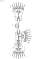
- Fig. 1 is a block diagram illustrating an example of the basic configuration of a multi-core multi-mode fiber coupling device of the present invention. As illustrated in Fig. 1 , this device comprises first fiber group 11, first light converging system 13, first mode converter 15, second fiber group 21, second light converging system 23, and multi-core fiber spatial coupling system 33.
- the first fiber group 11 refers to a group of two optical fibers or more which are provided at positions spatially away from each other.
- An example of the optical fibers constituting the first fiber group is a single mode fiber.
- the first light converging system 13 is an optical system for converging a group of outgoing light beams from the first fiber group 11.
- An example of the first light converging system 13 is a prism or a mirror for guiding a plurality of outgoing light beams from the first fiber group 11 into the first mode converter 15 (e.g., phase plate).
- the first light converging system 13 is a mirror, an optical path is adjusted so that light beams from a plurality of optical fibers existing spatially away from each other arrive at a predetermined position of a wavelength plate. In this way, a plurality of light beams from the first fiber group 11 are guided to a predetermined position of the first mode converter 15 by means of the first light converging system 13.
- the first mode converter 15 is an optical device for converting the mode of a group of outgoing light beams from the first fiber group 11, which have been converged by means of the first light converging system 13, into the first mode.
- An example of the first mode converter 15 is a phase plate. It is preferable that the first mode converter 15 is a phase plate arranged in a position where the group of outgoing light beams from the first fiber group 11 coincide with each other by means of the first light converging system 13.
- light beams included in the group of outgoing light beams from the first fiber group 11 may be simultaneously subjected to mode conversion, thereby making it possible to easily attain the multi-core multi-mode fiber coupling.
- the mode converter is known as disclosed in, e.g. the Japanese Patent Application Laid Open No. 2009-047784 publication, and the Japanese Patent Application Laid Open No. 2010-122688 publication.
- the mode converter can convert light beams of the base mode into light beams of any higher order mode.
- An output from the first fiber has ordinarily basic (base) mode (TEM 00 ).
- Light beams of the basic mode are subjected to mode conversion as occasion demands at the first mode converter 15.
- An example of the mode after it has undergone mode conversion is a first order mode (TEM 01 or TEM 10 ). Any mode (e.g., TEM 11 or TEM 02 ) except for the above may be used.
- a group of outgoing light beams from the first mode converter 15, which arrives at a multi-core multi-mode fiber are different in the mode from any other group of light beams.
- the multi-core multi-mode fiber when three kinds of groups of light beams are input into the multi-core multi-mode fiber, it is preferable to employ three modes of the base mode (the case where, e.g. an output from the single mode fiber is not subjected to mode conversion), TEM 01 and TEM 10 .
- Such modes are introduced into the multi-core multi-mode fiber, and any mode may be employed if it can be separated by using known means in a multi-core multi-mode fiber of the receiving side.
- a preferred example of the multi-core multi-mode fiber coupling device is an example in which light beams are converged on a predetermined position of the first mode converter 15 by means of the first light converging system 13.
- Fig. 2 is a view for explaining an example of the mode converter. As illustrated in Fig. 2 , this phase plate 16 indicates that there is a transparent medium having a specific refractive index in an adjacent intensity distribution in a spatial light in correspondence with the propagation mode within an optical fiber arranged, in order to allow a difference between phases of intensities adjacent in the spatial light in correspondence with the propagation mode within the optical fiber to be ⁇ (180°) to provide a physical optical path difference corresponding to a phase difference at that wavelength.
- the multi-core fiber has a plurality of cores in positions symmetrical with respect to the central core.
- the phase plate is such that the boundary between the thin part 17 and the thick part 18 linearly exists.
- light beams from the fiber, which have been once converged at this boundary are guided into respective cores of the multi-core.
- the second light converging system 23 is an optical system for converging a group of outgoing light beams from the second fiber group 21.
- a second mode converter adapted to perform mode conversion of the mode of the group of outgoing light beams from the second fiber group 21, which have been converged by the second light converging system 23, is not indispensable. This is because it is sufficient that any light signal in the base mode is included in the multi-core multi-mode fiber.
- the mode of a group of outgoing light beams from the second fiber group 21, which have been converged by means of the second light converging system 23, may be subjected to mode change or conversion by means of the second mode converter.
- the multi-core fiber spatial coupling system 33 is an optical system for guiding a group of outgoing light beams from the first mode converter 15 and a group of outgoing light beams from the second light converging system 23 into the multi-core fiber 31.
- the multi-core fiber spatial coupling system 33 guides respective plural light beams, which are included in the group of rays of outgoing light beams from the first mode converter 15 and the group of outgoing light beams from the second light converging system 23, into a corresponding one or ones of a plurality of cores of the multi-core multi-mode fiber.
- An example of such an optical system is an optical system in the multi-core fiber coupling device disclosed in the Japanese Patent Application Laid Open No. 2013-182222 publication.
- An example of the multi-core fiber spatial coupling system 33 is configured to comprise, as illustrated in Fig. 1 , a first relay lens to which a group of outgoing light beams from the first mode converter 15 are incident, and a beam splitter which guides light beams from the first relay lens and a group of outgoing light beams from the second light converging system 23 into the multi-core multi-mode fiber.
- An output from the beam splitter is propagated into the multi-mode fiber via a multi-mode fiber coupling lens, and respective ones of the group of light beams will be thus propagated into objective cores.
- the relay lens refers to a lens or a lens system for transmitting an image which has been formed at an optical system located forward towards further backward. Mismatch in size between a predetermined higher order mode in which multi light beams have been converted by the phase plate and the homogeneous mode in the fiber is optimized by means of the relay lens so that the maximum coupling efficiency can be provided.
- light beams included in the group of outgoing light beams from the first fiber group 11 are simultaneously subjected to mode conversion at the first mode converter 15, thereby making it possible to easily attain multi-core multi-mode fiber coupling.
- the light beams which have been emitted from the multi-core multi-mode fiber 31 are separated by a multi-core fiber coupling lens (multi-core fiber separation lens) 61 so that they are transmitted into a plurality of fibers 65 by means of an optical system 63.
- a multi-core fiber coupling lens multi-core fiber separation lens
- the present invention also provides a multi-core multi-mode fiber coupling method using the above-described multi-core multi-mode fiber coupling device. This method comprises steps described below.
- a group of outgoing light beams are emitted from the first fiber group 11.
- the group of outgoing light beams from the first fiber group 11 are converged by means of the first light converging system 13.
- the group of outgoing light beams from the first fiber group 11, which have been converged by means of the first light converging system 13, are subjected to mode conversion into the first mode by means of the first mode converter 15.
- a group of outgoing light beams are emitted from the second fiber group 21.
- the group of outgoing light beams from the second fiber group 21 are converged by means of the second light converging system 23.
- the group of outgoing light beams from the first mode converter 15 and the group of outgoing light beams from the second light converging system 23 are guided into the multi-core fiber 31 by means of the multi-core fiber spatial coupling system 33.
- Fig. 3 is a block diagram illustrating a preferred example of the multi-core multi-mode coupling device.
- the example illustrated in Fig. 3 further comprises, in addition to the components of the previously mentioned multi-core multi-mode coupling device, a third group of fibers 41 which will be hereinafter simply referred to as a third fiber group 41, a third light converging system 43 and a third mode converter 45.
- a third fiber group 41 which will be hereinafter simply referred to as a third fiber group 41
- a third light converging system 43 is an optical system for converging a group of outgoing light beams from the third fiber group 41.
- the third mode converter 45 is an optical device for converting the mode into a second mode of a group of outgoing light beams from the third fiber group 41, which have been converged by means of the third light converging system 43.
- the third fiber group 41, the third light converging system 43 and the third mode converter 45 have configurations similar to those of the first fiber group 11, the first light converging system 13 and the first mode converter 15, respectively.
- the multi-core fiber spatial coupling system 33 guides a group of outgoing light beams from the first mode converter 15, a group of outgoing light beams from the second light converging system 23, and a group of outgoing light beams from the third mode converter 45 into the multi-core fiber 31.
- the present invention also provides a multi-core multi-mode fiber coupling method using the above-described multi-core multi-mode fiber coupling device. This method comprises steps described below.
- a group of outgoing light beams are emitted from the first fiber group 11.
- the group of outgoing light beams from the first fiber group 11 are converged by means of the first light converging system 13.
- the group of outgoing light beams from the first fiber group 11, which have been converged by means of the first light converging system 13, are subjected to mode conversion into the first mode by means of the first mode converter 15.
- a group of outgoing light beams are emitted from the second fiber group 21.
- the group of outgoing light beams from the second fiber group 21 are converged by means of the second light converging system 23.
- a group of outgoing light beams are emitted from the third fiber group 41.
- the group of outgoing light beams from the third fiber group 41 are converged by means of the third light converging system 43.
- the group of outgoing light beams from the third fiber group 41, which have been converged by means of the third light converging system 43, are subjected to mode conversion into the second mode (the third mode when light beams of the second fiber group have been subjected to mode conversion into the second mode) by means of the third mode converter 45.
- the group of outgoing light beams from the first mode converter 15, the group of outgoing light beams from the second light converging system 23 and the group of outgoing light beams from the third mode converter 45 are guided into the multi-core fiber 31 by means of the multi-core fiber spatial coupling system 33.
- the present invention can be utilized in the field of the optical fiber communication using spatial division multiplexing and multi-core multi-mode fiber.
Landscapes
- Physics & Mathematics (AREA)
- General Physics & Mathematics (AREA)
- Optics & Photonics (AREA)
- Engineering & Computer Science (AREA)
- Computer Networks & Wireless Communication (AREA)
- Signal Processing (AREA)
- Electromagnetism (AREA)
- Optical Couplings Of Light Guides (AREA)
- Optical Communication System (AREA)
- Optical Integrated Circuits (AREA)
- Optical Fibers, Optical Fiber Cores, And Optical Fiber Bundles (AREA)
Abstract
Description
- The present invention relates to a multi-core multi-mode fiber coupling device configured to simultaneously convert light beams in a single mode from a plurality of fibers into a higher order mode to thereby have ability to effectively couple the plurality of single mode fibers and a multi-core multi-mode fiber, and a method of coupling a plurality of optical fibers and a multi-core multi-mode fiber using such a device.
- In recent years, the limit in transmission capacity of optical fibers has become a problem, and studies on Space Division Multiplexing (SDM) are thus being intensively made in order to solve such a problem. For this reason, multi-core fibers having a plurality of cores in a single fiber, and/or multi-mode fibers capable of transmitting a plurality of propagation modes through a single core are subject to study.
- In the Japanese Patent Application Laid Open No.
2013-182222 - In a non-Patent reference 1, there is a technology adapted for stretching a bundle fiber in a tapered shape to couple a multi-core fiber of 7-core and single mode fibers disclosed. With this technology, a plurality of single mode fibers are bundled and stretched to implement fusion splicing to the multi-core fiber.
- Patent reference 1: Japanese Patent Application Laid Open No.
2013-182222 - Non-patent reference 1: B. Zhu, et. al "Space-, Wavelength-, Polarization-Division Multiplexed Transmission of 56-Tb/s over a 76.8-km Seven-Core Fiber," in Optical Fiber Communication Conference, OSA Technical Digest (CD)(Optical Society of America, 2011), paper PDPB7.
- As described above, the limit in the transmission capacity of the optical fiber is considered to be a problem. For this reason, it is desirable to develop a multi-core multi-mode fiber coupling device which is able to transmit a large number of information, and to propose a multi-core multi-mode fiber coupling method using such a device.
- The present invention is fundamentally based on the finding that outgoing light beams from a plurality of multi-core couplers are subjected to mode multiplexing using an optical coupler (optical mode combiner) so that the multi-core multi-mode fiber coupling can be made.
- The present invention relates to a multi-core multi-mode fiber coupling device. This device comprises: a
first group 11 of fibers, which will be hereinafter simply referred to as afirst fiber group 11; a firstlight converging system 13, afirst mode converter 15; asecond group 21 of fibers, which will be hereinafter simply referred to as asecond fiber group 21; a secondlight converging system 23; and aspatial coupling system 33 for multi-core fiber, which will be hereinafter simply referred to as a multi-core fiberspatial coupling system 33. Thefirst mode converter 15 simultaneously implements thereat mode conversion to light beams from thefirst fiber group 11. The multi-core fiberspatial coupling system 33 multiplexes light beams originating from thefirst fiber group 11, which have been subjected to mode conversion, and light beams originating from thesecond fiber group 21 to transmit the light beam or beams thus obtained to amulti-core fiber 31. - The first
light converging system 13 is an optical system for converging a group of outgoing light beams from thefirst fiber group 11. Thefirst mode converter 15 is an optical device for converting the mode of the group of outgoing light beams from thefirst fiber group 11, which have been converged by means of the firstlight converging system 13, into a first mode. The secondlight converging system 23 is an optical system for converging a group of outgoing light beams from thesecond fiber group 21. - The multi-core fiber
spatial coupling system 33 is an optical system for multiplexing the group of light beams from thefirst mode converter 15 and the group of light beams from thesecond mode converter 23 to guide the multiplexed light beam or beams into themulti-core fiber 31. - When the first mode is the base mode, respective light beams, which have been converged by means of the first
light converging system 13, are passed through thefirst mode converter 15 which provides a distribution to allow a difference between phases adjacent in a spatial light in correspondence with the propagation mode within the optical fiber to be π (180°) to thereby have ability to perform conversion into a higher order mode. The multi-core multi-mode fiber coupling device of the present invention simultaneously implements mode conversion to a plurality of outgoing light beams from thefirst fiber group 11 by converging light beams into thefirst mode converter 15. It is preferable that thefirst mode converter 15 is a phase plate arranged at a position in which the group of outgoing light beams from thefirst fiber group 11 are allowed to coincide with each other by the firstlight converging system 13. This position may be also a position for realizing an optimum mode conversion efficiency as will be described later. - A more preferred example of the multi-core multi-mode fiber coupling device is a device further comprising: a
third group 41 of fibers, which will be hereinafter simply referred to as athird fiber group 41; a thirdlight converging system 43; and athird mode converter 45. The thirdlight converging system 43 is an optical system for converging a group of outgoing light beams from thethird fiber group 41. Thethird mode converter 45 is an optical device for performing mode conversion into a second mode of the group of outgoing light beams from thethird fiber group 41, which have been converged by means of the thirdlight converging system 43. - In the case of the above-mentioned example, the multi-core fiber
spatial coupling system 33 guides the group of outgoing light beams from thefirst mode converter 15, the group of outgoing light beams from the secondlight converging system 23 and the group of outgoing light beams from thethird mode converter 45, into themulti-core fiber 31. - The present invention also provides a multi-core multi-mode fiber coupling method using the above-described multi-core multi-mode fiber coupling device. This method comprises steps described below.
- A group of outgoing light beams are emitted from the
first fiber group 11. The group of outgoing light beams from thefirst fiber group 11 are converged by means of the firstlight converging system 13. The group of outgoing light beams from thefirst fiber group 11, which have been converged by means of the firstlight converging system 13, are subjected to mode conversion into the first mode by means of thefirst mode converter 15. - The group of outgoing light beams are emitted from the
second fiber group 21. The group of outgoing light beams from thesecond fiber group 21 are converged by means of the secondlight converging system 23. The group of outgoing light beams from thefirst mode converter 15 and the group of outgoing light beams from the secondlight converging system 23 are guided into themulti-core fiber 31 by means of the multi-core fiberspatial coupling system 33. - In accordance with the present invention, since multi-core multi-mode coupling device can be provided by means of a plurality of multi-core couplers and optical coupler (optical mode combiner), it is possible to realize multi-core multi-mode fiber coupling with lesser number of parts or components.
-
-
Fig. 1 is a block diagram illustrating an example of the basic configuration of a multi-core multi-mode fiber coupling device. -
Fig. 2 is a view for explaining an example of a mode converter. -
Fig. 3 is a block diagram illustrating a preferred example of the multi-core multi-mode fiber coupling device. - Preferred embodiments for carrying out the present invention will now be described with reference to the attached drawings. It is to be noted that the present invention is not limited to embodiments described below, but may include an embodiment or embodiments which has or have been modified or changed as occasion demands within the scope that the person skilled in the art knows from the embodiments described below.
- The present invention relates to a multi-core multi-mode fiber coupling device. The multi-core multi-mode fiber coupling device is configured to couple light beams from a plurality of light sources with a multi-core multi-mode fiber. Namely, such a device refers to a device adapted to guide light beams caused to be in a multi-mode including a plurality of higher order mode into respective cores of a multi-core fiber having a plurality of cores in a single optical fiber. There is no need for all cores included in the multi-core fiber to be used for optical information communication, but, e.g., any one of the central core and/or peripheral cores may be used for detection, and any feedback may be employed in advance as occasion demands.
-
Fig. 1 is a block diagram illustrating an example of the basic configuration of a multi-core multi-mode fiber coupling device of the present invention. As illustrated inFig. 1 , this device comprisesfirst fiber group 11, firstlight converging system 13,first mode converter 15,second fiber group 21, secondlight converging system 23, and multi-core fiberspatial coupling system 33. - The
first fiber group 11 refers to a group of two optical fibers or more which are provided at positions spatially away from each other. An example of the optical fibers constituting the first fiber group is a single mode fiber. - The first
light converging system 13 is an optical system for converging a group of outgoing light beams from thefirst fiber group 11. An example of the firstlight converging system 13 is a prism or a mirror for guiding a plurality of outgoing light beams from thefirst fiber group 11 into the first mode converter 15 (e.g., phase plate). When the firstlight converging system 13 is a mirror, an optical path is adjusted so that light beams from a plurality of optical fibers existing spatially away from each other arrive at a predetermined position of a wavelength plate. In this way, a plurality of light beams from thefirst fiber group 11 are guided to a predetermined position of thefirst mode converter 15 by means of the firstlight converging system 13. However, in the case of an arrangement which can conduct a guide to a predetermined position of thefirst mode converter 15 without relying on the firstlight converging system 13, it is not necessarily required to use the firstlight converging system 13. - The
first mode converter 15 is an optical device for converting the mode of a group of outgoing light beams from thefirst fiber group 11, which have been converged by means of the firstlight converging system 13, into the first mode. An example of thefirst mode converter 15 is a phase plate. It is preferable that thefirst mode converter 15 is a phase plate arranged in a position where the group of outgoing light beams from thefirst fiber group 11 coincide with each other by means of the firstlight converging system 13. In thefirst mode converter 15, light beams included in the group of outgoing light beams from thefirst fiber group 11 may be simultaneously subjected to mode conversion, thereby making it possible to easily attain the multi-core multi-mode fiber coupling. - The mode converter is known as disclosed in, e.g. the Japanese Patent Application Laid Open No.
2009-047784 2010-122688 first mode converter 15. An example of the mode after it has undergone mode conversion is a first order mode (TEM01 or TEM10). Any mode (e.g., TEM11 or TEM02) except for the above may be used. On the other hand, it is preferable that a group of outgoing light beams from thefirst mode converter 15, which arrives at a multi-core multi-mode fiber, are different in the mode from any other group of light beams. - For example, when three kinds of groups of light beams are input into the multi-core multi-mode fiber, it is preferable to employ three modes of the base mode (the case where, e.g. an output from the single mode fiber is not subjected to mode conversion), TEM01 and TEM10. Such modes are introduced into the multi-core multi-mode fiber, and any mode may be employed if it can be separated by using known means in a multi-core multi-mode fiber of the receiving side.
- A preferred example of the multi-core multi-mode fiber coupling device is an example in which light beams are converged on a predetermined position of the
first mode converter 15 by means of the firstlight converging system 13.Fig. 2 is a view for explaining an example of the mode converter. As illustrated inFig. 2 , thisphase plate 16 indicates that there is a transparent medium having a specific refractive index in an adjacent intensity distribution in a spatial light in correspondence with the propagation mode within an optical fiber arranged, in order to allow a difference between phases of intensities adjacent in the spatial light in correspondence with the propagation mode within the optical fiber to be π (180°) to provide a physical optical path difference corresponding to a phase difference at that wavelength. In this drawing, since light beams 19, which are arranged so that they are uniformly irradiated onto respective thin andthick parts - Ordinarily, the multi-core fiber has a plurality of cores in positions symmetrical with respect to the central core. Moreover, the phase plate is such that the boundary between the
thin part 17 and thethick part 18 linearly exists. In the present invention, light beams from the fiber, which have been once converged at this boundary, are guided into respective cores of the multi-core. - The second
light converging system 23 is an optical system for converging a group of outgoing light beams from thesecond fiber group 21. In this example, such a second mode converter adapted to perform mode conversion of the mode of the group of outgoing light beams from thesecond fiber group 21, which have been converged by the secondlight converging system 23, is not indispensable. This is because it is sufficient that any light signal in the base mode is included in the multi-core multi-mode fiber. On the other hand, the mode of a group of outgoing light beams from thesecond fiber group 21, which have been converged by means of the secondlight converging system 23, may be subjected to mode change or conversion by means of the second mode converter. - The multi-core fiber
spatial coupling system 33 is an optical system for guiding a group of outgoing light beams from thefirst mode converter 15 and a group of outgoing light beams from the secondlight converging system 23 into themulti-core fiber 31. The multi-core fiberspatial coupling system 33 guides respective plural light beams, which are included in the group of rays of outgoing light beams from thefirst mode converter 15 and the group of outgoing light beams from the secondlight converging system 23, into a corresponding one or ones of a plurality of cores of the multi-core multi-mode fiber. An example of such an optical system is an optical system in the multi-core fiber coupling device disclosed in the Japanese Patent Application Laid Open No.2013-182222 - An example of the multi-core fiber
spatial coupling system 33 is configured to comprise, as illustrated inFig. 1 , a first relay lens to which a group of outgoing light beams from thefirst mode converter 15 are incident, and a beam splitter which guides light beams from the first relay lens and a group of outgoing light beams from the secondlight converging system 23 into the multi-core multi-mode fiber. An output from the beam splitter is propagated into the multi-mode fiber via a multi-mode fiber coupling lens, and respective ones of the group of light beams will be thus propagated into objective cores. The relay lens refers to a lens or a lens system for transmitting an image which has been formed at an optical system located forward towards further backward. Mismatch in size between a predetermined higher order mode in which multi light beams have been converted by the phase plate and the homogeneous mode in the fiber is optimized by means of the relay lens so that the maximum coupling efficiency can be provided. - As described above, light beams included in the group of outgoing light beams from the
first fiber group 11 are simultaneously subjected to mode conversion at thefirst mode converter 15, thereby making it possible to easily attain multi-core multi-mode fiber coupling. - The light beams which have been emitted from the multi-core
multi-mode fiber 31 are separated by a multi-core fiber coupling lens (multi-core fiber separation lens) 61 so that they are transmitted into a plurality offibers 65 by means of anoptical system 63. - The present invention also provides a multi-core multi-mode fiber coupling method using the above-described multi-core multi-mode fiber coupling device. This method comprises steps described below.
- A group of outgoing light beams are emitted from the
first fiber group 11. The group of outgoing light beams from thefirst fiber group 11 are converged by means of the firstlight converging system 13. The group of outgoing light beams from thefirst fiber group 11, which have been converged by means of the firstlight converging system 13, are subjected to mode conversion into the first mode by means of thefirst mode converter 15. - A group of outgoing light beams are emitted from the
second fiber group 21. The group of outgoing light beams from thesecond fiber group 21 are converged by means of the secondlight converging system 23. The group of outgoing light beams from thefirst mode converter 15 and the group of outgoing light beams from the secondlight converging system 23 are guided into themulti-core fiber 31 by means of the multi-core fiberspatial coupling system 33. -
Fig. 3 is a block diagram illustrating a preferred example of the multi-core multi-mode coupling device. The example illustrated inFig. 3 further comprises, in addition to the components of the previously mentioned multi-core multi-mode coupling device, a third group offibers 41 which will be hereinafter simply referred to as athird fiber group 41, a thirdlight converging system 43 and athird mode converter 45. By using the same principle as described above, it is possible to guide a group of light beams having a larger number of modes into the multi-core multi-mode fiber. The thirdlight converging system 43 is an optical system for converging a group of outgoing light beams from thethird fiber group 41. Thethird mode converter 45 is an optical device for converting the mode into a second mode of a group of outgoing light beams from thethird fiber group 41, which have been converged by means of the thirdlight converging system 43. Thethird fiber group 41, the thirdlight converging system 43 and thethird mode converter 45 have configurations similar to those of thefirst fiber group 11, the firstlight converging system 13 and thefirst mode converter 15, respectively. - In the case of this example, the multi-core fiber
spatial coupling system 33 guides a group of outgoing light beams from thefirst mode converter 15, a group of outgoing light beams from the secondlight converging system 23, and a group of outgoing light beams from thethird mode converter 45 into themulti-core fiber 31. - The present invention also provides a multi-core multi-mode fiber coupling method using the above-described multi-core multi-mode fiber coupling device. This method comprises steps described below.
- A group of outgoing light beams are emitted from the
first fiber group 11. The group of outgoing light beams from thefirst fiber group 11 are converged by means of the firstlight converging system 13. The group of outgoing light beams from thefirst fiber group 11, which have been converged by means of the firstlight converging system 13, are subjected to mode conversion into the first mode by means of thefirst mode converter 15. - A group of outgoing light beams are emitted from the
second fiber group 21. The group of outgoing light beams from thesecond fiber group 21 are converged by means of the secondlight converging system 23. - A group of outgoing light beams are emitted from the
third fiber group 41. The group of outgoing light beams from thethird fiber group 41 are converged by means of the thirdlight converging system 43. The group of outgoing light beams from thethird fiber group 41, which have been converged by means of the thirdlight converging system 43, are subjected to mode conversion into the second mode (the third mode when light beams of the second fiber group have been subjected to mode conversion into the second mode) by means of thethird mode converter 45. The group of outgoing light beams from thefirst mode converter 15, the group of outgoing light beams from the secondlight converging system 23 and the group of outgoing light beams from thethird mode converter 45 are guided into themulti-core fiber 31 by means of the multi-core fiberspatial coupling system 33. - The present invention can be utilized in the field of the optical fiber communication using spatial division multiplexing and multi-core multi-mode fiber.
-
- 11
- First fiber group
- 13
- First light converging system
- 15
- First mode converter
- 21
- Second fiber group
- 23
- Second light converging system
- 31
- Multi-core fiber
- 33
- Multi-core fiber spatial coupling system
- 41
- Third fiber group
- 43
- Third light converging system
- 45
- Third mode converter
- 61
- Multi-core fiber coupling lens
- 63
- Optical system
- 65
- Fiber
Claims (4)
- A multi-core multi-mode fiber coupling device comprising:a first group (11) of fibers;a first light converging system (13) which converges a group of outgoing light beams from the first group (11) of fibers;a first mode converter (15) which converts a mode of the group of outgoing light beams from the first group (11) of fibers, which has been converged by the first light converging system (13), into a first mode;a second group (21) of fibers;a second light converging system (23) which converges a group of outgoing light beams from the second group (21) of fibers, anda spatial coupling system (33) for multi-core fiber which guides a group of outgoing light beams from the first mode converter (15) and a group of outgoing light beams from the second light converging system (23) into a multi-core fiber (31).
- The multi-core multi-mode fiber coupling device according to claim 1,
wherein the first mode converter (15) is a phase plate provided at a position in which a group of outgoing light beams from the first group (11) of fibers is allowed to coincide with each other by the first light converging system (13). - The multi-core multi-mode fiber coupling device according to claim 1,
wherein the device further comprises:a third group (41) of fibers;a third light converging system (43) which converges a group of outgoing light beams from the third group (41) of fibers; anda third mode converter (45) which converts a mode into a second mode of the group of outgoing light beams from the third group (41) of fibers, which has been converged by means of the third light converging system (43),wherein the spatial coupling system (33) for multi-core fiber guides a group of outgoing light beams from the first mode converter (15), a group of outgoing light beams from the second light converging system (23), and a group of outgoing light beams from the third mode converter (45) into the multi-core fiber (31). - A multi-core multi-mode fiber coupling method comprising:a step in which a group of outgoing light beams is emitted from a first group (11) of fibers;a step in which the group of outgoing light beams from the first group (11) of fibers is converged by a first light converging system (13);a step in which the group of outgoing light beams from the first group (11) of fibers, which has been converged by means of the first light converging system (13), is subjected to mode conversion into a first mode by the first mode converter (15);a step in which a group of outgoing light beams is emitted from a second group (21) of fibers;a step in which the group of outgoing light beams from the second group (21) of fibers is converged by a second light converging system (23); anda step in which a group of outgoing light beams from the first mode converter (15) and a group of outgoing light beams from the second light converging system (23) are guided into a multi-core fiber (31) by a spatial coupling system (33) for multi-core fiber.
Applications Claiming Priority (2)
| Application Number | Priority Date | Filing Date | Title |
|---|---|---|---|
| JP2014090704A JP5957718B2 (en) | 2014-04-24 | 2014-04-24 | Multi-core multi-mode fiber coupler |
| PCT/JP2015/060708 WO2015163124A1 (en) | 2014-04-24 | 2015-04-06 | Multicore/multimode fiber joining device |
Publications (3)
| Publication Number | Publication Date |
|---|---|
| EP3136145A1 true EP3136145A1 (en) | 2017-03-01 |
| EP3136145A4 EP3136145A4 (en) | 2017-12-20 |
| EP3136145B1 EP3136145B1 (en) | 2021-07-14 |
Family
ID=54332291
Family Applications (1)
| Application Number | Title | Priority Date | Filing Date |
|---|---|---|---|
| EP15782719.7A Active EP3136145B1 (en) | 2014-04-24 | 2015-04-06 | Multicore/multimode fiber joining device |
Country Status (6)
| Country | Link |
|---|---|
| US (1) | US20170045687A1 (en) |
| EP (1) | EP3136145B1 (en) |
| JP (1) | JP5957718B2 (en) |
| CN (1) | CN106461868B (en) |
| DK (1) | DK3136145T3 (en) |
| WO (1) | WO2015163124A1 (en) |
Families Citing this family (7)
| Publication number | Priority date | Publication date | Assignee | Title |
|---|---|---|---|---|
| FR3049135B1 (en) * | 2016-03-15 | 2020-02-14 | Cailabs | MULTIMODE FIBER OPTIC COMMUNICATIONS DEVICE WITH MODAL DISPERSION COMPENSATION COMPONENT |
| CN107797181B (en) * | 2016-08-31 | 2020-04-28 | 华为技术有限公司 | Optical switch matrix and control method thereof |
| CN108508536A (en) * | 2018-04-11 | 2018-09-07 | 武汉中科锐择光电科技有限公司 | A kind of complete optical fiber polarization beam splitter |
| US11927802B2 (en) * | 2018-10-15 | 2024-03-12 | Sumitomo Electric Industries, Ltd. | Optical module and method for manufacturing optical module |
| CN116466445A (en) * | 2022-01-12 | 2023-07-21 | 华为技术有限公司 | Optical receiving module, device and method |
| WO2023176085A1 (en) * | 2022-03-17 | 2023-09-21 | 住友電気工業株式会社 | Multicore optical fiber, optical combiner, and fiber properties measurement method |
| CN115694645B (en) * | 2022-11-01 | 2024-06-25 | 南京信息工程大学 | Mode selection fiber core replacement multimode multi-core optical communication system with balanced adjustment of mold cores |
Family Cites Families (7)
| Publication number | Priority date | Publication date | Assignee | Title |
|---|---|---|---|---|
| CN1261779C (en) * | 2001-10-19 | 2006-06-28 | Ntt电子股份有限公司 | Arrayed Waveguide Diffraction Grating Type Optical Multiplexer/Demultiplexer |
| KR100594040B1 (en) * | 2004-01-08 | 2006-06-30 | 삼성전자주식회사 | Dual Band Wavelength Division Multiplexer |
| WO2012088361A2 (en) * | 2010-12-21 | 2012-06-28 | Ofs Fitel, Llc | Multicore collimator |
| CN102096150B (en) * | 2010-12-22 | 2013-04-17 | 北京大学 | Multi-core fiber based optical transmission structure and device applying same |
| CN103185919B (en) * | 2011-12-30 | 2015-06-17 | 清华大学 | Coupling device of multimode optical fibers with cladding |
| JP5870426B2 (en) * | 2012-03-04 | 2016-03-01 | 国立研究開発法人情報通信研究機構 | Multi-core fiber coupler |
| US8867125B2 (en) * | 2012-08-24 | 2014-10-21 | Alcatel Lucent | Multi-mode optical fiber amplifier |
-
2014
- 2014-04-24 JP JP2014090704A patent/JP5957718B2/en active Active
-
2015
- 2015-04-06 US US15/306,104 patent/US20170045687A1/en not_active Abandoned
- 2015-04-06 WO PCT/JP2015/060708 patent/WO2015163124A1/en not_active Ceased
- 2015-04-06 DK DK15782719.7T patent/DK3136145T3/en active
- 2015-04-06 EP EP15782719.7A patent/EP3136145B1/en active Active
- 2015-04-06 CN CN201580020765.4A patent/CN106461868B/en active Active
Also Published As
| Publication number | Publication date |
|---|---|
| CN106461868A (en) | 2017-02-22 |
| EP3136145A4 (en) | 2017-12-20 |
| JP5957718B2 (en) | 2016-07-27 |
| CN106461868B (en) | 2019-07-19 |
| US20170045687A1 (en) | 2017-02-16 |
| WO2015163124A1 (en) | 2015-10-29 |
| DK3136145T3 (en) | 2021-09-06 |
| EP3136145B1 (en) | 2021-07-14 |
| JP2015210339A (en) | 2015-11-24 |
Similar Documents
| Publication | Publication Date | Title |
|---|---|---|
| EP3136145B1 (en) | Multicore/multimode fiber joining device | |
| US10338308B2 (en) | Method and system for partial integration of wavelength division multiplexing and bi-directional solutions | |
| KR101047121B1 (en) | Multichannel Optical Transmitter, and Active Alignment Method of Receiver | |
| KR101399556B1 (en) | Method and device for transmitting optical information between an emitter station and receiving station via a multi-mode optical wave guide | |
| US11516562B2 (en) | Core selective switch and optical node device | |
| US9766405B2 (en) | System and method for photonic detection and excitation of multiple fibre modes | |
| US20190173604A1 (en) | High-speed optical transceiver based on cwdm and sdm | |
| US11201675B2 (en) | Method and system for a bi-directional multi-wavelength receiver for standard single-mode fiber based on grating couplers | |
| JPWO2017090608A1 (en) | Node and optical power supply system | |
| US9525508B2 (en) | Mode division multiplexing optical link | |
| JP6219288B2 (en) | Multi-core fiber and single-mode fiber optical connector | |
| Chen et al. | 30Gbit/s 3× 3 optical mode group division multiplexing system with mode-selective spatial filtering | |
| KR20170010478A (en) | Optical transmitting/receiving apparatus for input/output mode control and optical transmission system using the same | |
| US10020888B1 (en) | Transmitter and receiver for direct communication of multiple optical wavelengths via an optical link | |
| Blau et al. | Optimization of spatial aperture-sampled mode multiplexer for a three-mode fiber | |
| Goto et al. | LCOS-based flexible optical switch for heterogeneous SDM fiber networks | |
| Goto et al. | Investigation of spatial mode conversion in flexible optical switch using LCOS-based spatial light modulator | |
| KR20100050024A (en) | A system for transmitting optical signal | |
| JP2018189691A (en) | Optical device, communication system and multiplexing/demultiplexing method | |
| Mizuno et al. | Dense space division multiplexed transmission technology | |
| Rosenkranz et al. | Optical MIMO-processing and mode-multiplexing: Experimental achievements and future perspectives | |
| JP2019015910A (en) | Optical device, communication system, and multiplexing / demultiplexing method | |
| CN110149150A (en) | Communication multiplex system and method based on column vector beam (CVB) | |
| Al Amin et al. | Concept of a photonic integrated spatial mode multiplexer/demultiplexer chip for FMF transmission |
Legal Events
| Date | Code | Title | Description |
|---|---|---|---|
| STAA | Information on the status of an ep patent application or granted ep patent |
Free format text: STATUS: THE INTERNATIONAL PUBLICATION HAS BEEN MADE |
|
| PUAI | Public reference made under article 153(3) epc to a published international application that has entered the european phase |
Free format text: ORIGINAL CODE: 0009012 |
|
| STAA | Information on the status of an ep patent application or granted ep patent |
Free format text: STATUS: REQUEST FOR EXAMINATION WAS MADE |
|
| 17P | Request for examination filed |
Effective date: 20161021 |
|
| AK | Designated contracting states |
Kind code of ref document: A1 Designated state(s): AL AT BE BG CH CY CZ DE DK EE ES FI FR GB GR HR HU IE IS IT LI LT LU LV MC MK MT NL NO PL PT RO RS SE SI SK SM TR |
|
| AX | Request for extension of the european patent |
Extension state: BA ME |
|
| DAV | Request for validation of the european patent (deleted) | ||
| DAX | Request for extension of the european patent (deleted) | ||
| REG | Reference to a national code |
Ref country code: DE Ref legal event code: R079 Ref document number: 602015071320 Country of ref document: DE Free format text: PREVIOUS MAIN CLASS: G02B0006260000 Ipc: G02B0006270000 |
|
| A4 | Supplementary search report drawn up and despatched |
Effective date: 20171122 |
|
| RIC1 | Information provided on ipc code assigned before grant |
Ipc: G02B 6/27 20060101AFI20171116BHEP Ipc: G02B 6/28 20060101ALI20171116BHEP Ipc: H04J 14/04 20060101ALI20171116BHEP Ipc: H04B 10/2581 20130101ALI20171116BHEP |
|
| STAA | Information on the status of an ep patent application or granted ep patent |
Free format text: STATUS: EXAMINATION IS IN PROGRESS |
|
| 17Q | First examination report despatched |
Effective date: 20200210 |
|
| GRAP | Despatch of communication of intention to grant a patent |
Free format text: ORIGINAL CODE: EPIDOSNIGR1 |
|
| STAA | Information on the status of an ep patent application or granted ep patent |
Free format text: STATUS: GRANT OF PATENT IS INTENDED |
|
| INTG | Intention to grant announced |
Effective date: 20210219 |
|
| RIN1 | Information on inventor provided before grant (corrected) |
Inventor name: KOBAYASHI, TETSUYA Inventor name: AWAJI, YOSHINARI Inventor name: TAKAHATA, TAKETOSHI |
|
| GRAS | Grant fee paid |
Free format text: ORIGINAL CODE: EPIDOSNIGR3 |
|
| GRAA | (expected) grant |
Free format text: ORIGINAL CODE: 0009210 |
|
| STAA | Information on the status of an ep patent application or granted ep patent |
Free format text: STATUS: THE PATENT HAS BEEN GRANTED |
|
| AK | Designated contracting states |
Kind code of ref document: B1 Designated state(s): AL AT BE BG CH CY CZ DE DK EE ES FI FR GB GR HR HU IE IS IT LI LT LU LV MC MK MT NL NO PL PT RO RS SE SI SK SM TR |
|
| REG | Reference to a national code |
Ref country code: GB Ref legal event code: FG4D |
|
| REG | Reference to a national code |
Ref country code: IE Ref legal event code: FG4D |
|
| REG | Reference to a national code |
Ref country code: DE Ref legal event code: R096 Ref document number: 602015071320 Country of ref document: DE |
|
| REG | Reference to a national code |
Ref country code: AT Ref legal event code: REF Ref document number: 1411111 Country of ref document: AT Kind code of ref document: T Effective date: 20210815 |
|
| REG | Reference to a national code |
Ref country code: DK Ref legal event code: T3 Effective date: 20210831 |
|
| REG | Reference to a national code |
Ref country code: LT Ref legal event code: MG9D |
|
| REG | Reference to a national code |
Ref country code: NL Ref legal event code: MP Effective date: 20210714 |
|
| REG | Reference to a national code |
Ref country code: AT Ref legal event code: MK05 Ref document number: 1411111 Country of ref document: AT Kind code of ref document: T Effective date: 20210714 |
|
| PG25 | Lapsed in a contracting state [announced via postgrant information from national office to epo] |
Ref country code: NO Free format text: LAPSE BECAUSE OF FAILURE TO SUBMIT A TRANSLATION OF THE DESCRIPTION OR TO PAY THE FEE WITHIN THE PRESCRIBED TIME-LIMIT Effective date: 20211014 Ref country code: PT Free format text: LAPSE BECAUSE OF FAILURE TO SUBMIT A TRANSLATION OF THE DESCRIPTION OR TO PAY THE FEE WITHIN THE PRESCRIBED TIME-LIMIT Effective date: 20211115 Ref country code: NL Free format text: LAPSE BECAUSE OF FAILURE TO SUBMIT A TRANSLATION OF THE DESCRIPTION OR TO PAY THE FEE WITHIN THE PRESCRIBED TIME-LIMIT Effective date: 20210714 Ref country code: FI Free format text: LAPSE BECAUSE OF FAILURE TO SUBMIT A TRANSLATION OF THE DESCRIPTION OR TO PAY THE FEE WITHIN THE PRESCRIBED TIME-LIMIT Effective date: 20210714 Ref country code: ES Free format text: LAPSE BECAUSE OF FAILURE TO SUBMIT A TRANSLATION OF THE DESCRIPTION OR TO PAY THE FEE WITHIN THE PRESCRIBED TIME-LIMIT Effective date: 20210714 Ref country code: LT Free format text: LAPSE BECAUSE OF FAILURE TO SUBMIT A TRANSLATION OF THE DESCRIPTION OR TO PAY THE FEE WITHIN THE PRESCRIBED TIME-LIMIT Effective date: 20210714 Ref country code: BG Free format text: LAPSE BECAUSE OF FAILURE TO SUBMIT A TRANSLATION OF THE DESCRIPTION OR TO PAY THE FEE WITHIN THE PRESCRIBED TIME-LIMIT Effective date: 20211014 Ref country code: AT Free format text: LAPSE BECAUSE OF FAILURE TO SUBMIT A TRANSLATION OF THE DESCRIPTION OR TO PAY THE FEE WITHIN THE PRESCRIBED TIME-LIMIT Effective date: 20210714 Ref country code: SE Free format text: LAPSE BECAUSE OF FAILURE TO SUBMIT A TRANSLATION OF THE DESCRIPTION OR TO PAY THE FEE WITHIN THE PRESCRIBED TIME-LIMIT Effective date: 20210714 Ref country code: RS Free format text: LAPSE BECAUSE OF FAILURE TO SUBMIT A TRANSLATION OF THE DESCRIPTION OR TO PAY THE FEE WITHIN THE PRESCRIBED TIME-LIMIT Effective date: 20210714 Ref country code: HR Free format text: LAPSE BECAUSE OF FAILURE TO SUBMIT A TRANSLATION OF THE DESCRIPTION OR TO PAY THE FEE WITHIN THE PRESCRIBED TIME-LIMIT Effective date: 20210714 |
|
| PG25 | Lapsed in a contracting state [announced via postgrant information from national office to epo] |
Ref country code: PL Free format text: LAPSE BECAUSE OF FAILURE TO SUBMIT A TRANSLATION OF THE DESCRIPTION OR TO PAY THE FEE WITHIN THE PRESCRIBED TIME-LIMIT Effective date: 20210714 Ref country code: LV Free format text: LAPSE BECAUSE OF FAILURE TO SUBMIT A TRANSLATION OF THE DESCRIPTION OR TO PAY THE FEE WITHIN THE PRESCRIBED TIME-LIMIT Effective date: 20210714 Ref country code: GR Free format text: LAPSE BECAUSE OF FAILURE TO SUBMIT A TRANSLATION OF THE DESCRIPTION OR TO PAY THE FEE WITHIN THE PRESCRIBED TIME-LIMIT Effective date: 20211015 |
|
| REG | Reference to a national code |
Ref country code: DE Ref legal event code: R097 Ref document number: 602015071320 Country of ref document: DE |
|
| PLBE | No opposition filed within time limit |
Free format text: ORIGINAL CODE: 0009261 |
|
| STAA | Information on the status of an ep patent application or granted ep patent |
Free format text: STATUS: NO OPPOSITION FILED WITHIN TIME LIMIT |
|
| PG25 | Lapsed in a contracting state [announced via postgrant information from national office to epo] |
Ref country code: SM Free format text: LAPSE BECAUSE OF FAILURE TO SUBMIT A TRANSLATION OF THE DESCRIPTION OR TO PAY THE FEE WITHIN THE PRESCRIBED TIME-LIMIT Effective date: 20210714 Ref country code: SK Free format text: LAPSE BECAUSE OF FAILURE TO SUBMIT A TRANSLATION OF THE DESCRIPTION OR TO PAY THE FEE WITHIN THE PRESCRIBED TIME-LIMIT Effective date: 20210714 Ref country code: RO Free format text: LAPSE BECAUSE OF FAILURE TO SUBMIT A TRANSLATION OF THE DESCRIPTION OR TO PAY THE FEE WITHIN THE PRESCRIBED TIME-LIMIT Effective date: 20210714 Ref country code: EE Free format text: LAPSE BECAUSE OF FAILURE TO SUBMIT A TRANSLATION OF THE DESCRIPTION OR TO PAY THE FEE WITHIN THE PRESCRIBED TIME-LIMIT Effective date: 20210714 Ref country code: CZ Free format text: LAPSE BECAUSE OF FAILURE TO SUBMIT A TRANSLATION OF THE DESCRIPTION OR TO PAY THE FEE WITHIN THE PRESCRIBED TIME-LIMIT Effective date: 20210714 Ref country code: AL Free format text: LAPSE BECAUSE OF FAILURE TO SUBMIT A TRANSLATION OF THE DESCRIPTION OR TO PAY THE FEE WITHIN THE PRESCRIBED TIME-LIMIT Effective date: 20210714 |
|
| 26N | No opposition filed |
Effective date: 20220419 |
|
| PG25 | Lapsed in a contracting state [announced via postgrant information from national office to epo] |
Ref country code: IT Free format text: LAPSE BECAUSE OF FAILURE TO SUBMIT A TRANSLATION OF THE DESCRIPTION OR TO PAY THE FEE WITHIN THE PRESCRIBED TIME-LIMIT Effective date: 20210714 |
|
| REG | Reference to a national code |
Ref country code: CH Ref legal event code: PL |
|
| REG | Reference to a national code |
Ref country code: BE Ref legal event code: MM Effective date: 20220430 |
|
| PG25 | Lapsed in a contracting state [announced via postgrant information from national office to epo] |
Ref country code: MC Free format text: LAPSE BECAUSE OF FAILURE TO SUBMIT A TRANSLATION OF THE DESCRIPTION OR TO PAY THE FEE WITHIN THE PRESCRIBED TIME-LIMIT Effective date: 20210714 Ref country code: LU Free format text: LAPSE BECAUSE OF NON-PAYMENT OF DUE FEES Effective date: 20220406 Ref country code: LI Free format text: LAPSE BECAUSE OF NON-PAYMENT OF DUE FEES Effective date: 20220430 Ref country code: CH Free format text: LAPSE BECAUSE OF NON-PAYMENT OF DUE FEES Effective date: 20220430 |
|
| PG25 | Lapsed in a contracting state [announced via postgrant information from national office to epo] |
Ref country code: BE Free format text: LAPSE BECAUSE OF NON-PAYMENT OF DUE FEES Effective date: 20220430 |
|
| PG25 | Lapsed in a contracting state [announced via postgrant information from national office to epo] |
Ref country code: IE Free format text: LAPSE BECAUSE OF NON-PAYMENT OF DUE FEES Effective date: 20220406 |
|
| PG25 | Lapsed in a contracting state [announced via postgrant information from national office to epo] |
Ref country code: HU Free format text: LAPSE BECAUSE OF FAILURE TO SUBMIT A TRANSLATION OF THE DESCRIPTION OR TO PAY THE FEE WITHIN THE PRESCRIBED TIME-LIMIT; INVALID AB INITIO Effective date: 20150406 |
|
| PG25 | Lapsed in a contracting state [announced via postgrant information from national office to epo] |
Ref country code: MK Free format text: LAPSE BECAUSE OF FAILURE TO SUBMIT A TRANSLATION OF THE DESCRIPTION OR TO PAY THE FEE WITHIN THE PRESCRIBED TIME-LIMIT Effective date: 20210714 Ref country code: CY Free format text: LAPSE BECAUSE OF FAILURE TO SUBMIT A TRANSLATION OF THE DESCRIPTION OR TO PAY THE FEE WITHIN THE PRESCRIBED TIME-LIMIT Effective date: 20210714 |
|
| PG25 | Lapsed in a contracting state [announced via postgrant information from national office to epo] |
Ref country code: MT Free format text: LAPSE BECAUSE OF FAILURE TO SUBMIT A TRANSLATION OF THE DESCRIPTION OR TO PAY THE FEE WITHIN THE PRESCRIBED TIME-LIMIT Effective date: 20210714 |
|
| PGFP | Annual fee paid to national office [announced via postgrant information from national office to epo] |
Ref country code: DE Payment date: 20250422 Year of fee payment: 11 |
|
| PGFP | Annual fee paid to national office [announced via postgrant information from national office to epo] |
Ref country code: GB Payment date: 20250423 Year of fee payment: 11 Ref country code: DK Payment date: 20250429 Year of fee payment: 11 |
|
| PGFP | Annual fee paid to national office [announced via postgrant information from national office to epo] |
Ref country code: FR Payment date: 20250425 Year of fee payment: 11 |
|
| PG25 | Lapsed in a contracting state [announced via postgrant information from national office to epo] |
Ref country code: TR Free format text: LAPSE BECAUSE OF FAILURE TO SUBMIT A TRANSLATION OF THE DESCRIPTION OR TO PAY THE FEE WITHIN THE PRESCRIBED TIME-LIMIT Effective date: 20210714 |