EP3136132A1 - Direct resistivity determination - Google Patents
Direct resistivity determination Download PDFInfo
- Publication number
- EP3136132A1 EP3136132A1 EP16186030.9A EP16186030A EP3136132A1 EP 3136132 A1 EP3136132 A1 EP 3136132A1 EP 16186030 A EP16186030 A EP 16186030A EP 3136132 A1 EP3136132 A1 EP 3136132A1
- Authority
- EP
- European Patent Office
- Prior art keywords
- transformation
- bvp
- measured
- field data
- conductivity
- Prior art date
- Legal status (The legal status is an assumption and is not a legal conclusion. Google has not performed a legal analysis and makes no representation as to the accuracy of the status listed.)
- Granted
Links
Images

Classifications
-
- G—PHYSICS
- G01—MEASURING; TESTING
- G01V—GEOPHYSICS; GRAVITATIONAL MEASUREMENTS; DETECTING MASSES OR OBJECTS; TAGS
- G01V3/00—Electric or magnetic prospecting or detecting; Measuring magnetic field characteristics of the earth, e.g. declination, deviation
- G01V3/08—Electric or magnetic prospecting or detecting; Measuring magnetic field characteristics of the earth, e.g. declination, deviation operating with magnetic or electric fields produced or modified by objects or geological structures or by detecting devices
- G01V3/083—Controlled source electromagnetic [CSEM] surveying
-
- G—PHYSICS
- G01—MEASURING; TESTING
- G01V—GEOPHYSICS; GRAVITATIONAL MEASUREMENTS; DETECTING MASSES OR OBJECTS; TAGS
- G01V1/00—Seismology; Seismic or acoustic prospecting or detecting
- G01V1/38—Seismology; Seismic or acoustic prospecting or detecting specially adapted for water-covered areas
- G01V1/3808—Seismic data acquisition, e.g. survey design
-
- G—PHYSICS
- G01—MEASURING; TESTING
- G01V—GEOPHYSICS; GRAVITATIONAL MEASUREMENTS; DETECTING MASSES OR OBJECTS; TAGS
- G01V3/00—Electric or magnetic prospecting or detecting; Measuring magnetic field characteristics of the earth, e.g. declination, deviation
- G01V3/15—Electric or magnetic prospecting or detecting; Measuring magnetic field characteristics of the earth, e.g. declination, deviation specially adapted for use during transport, e.g. by a person, vehicle or boat
- G01V3/17—Electric or magnetic prospecting or detecting; Measuring magnetic field characteristics of the earth, e.g. declination, deviation specially adapted for use during transport, e.g. by a person, vehicle or boat operating with electromagnetic waves
-
- G—PHYSICS
- G01—MEASURING; TESTING
- G01V—GEOPHYSICS; GRAVITATIONAL MEASUREMENTS; DETECTING MASSES OR OBJECTS; TAGS
- G01V3/00—Electric or magnetic prospecting or detecting; Measuring magnetic field characteristics of the earth, e.g. declination, deviation
- G01V3/08—Electric or magnetic prospecting or detecting; Measuring magnetic field characteristics of the earth, e.g. declination, deviation operating with magnetic or electric fields produced or modified by objects or geological structures or by detecting devices
- G01V3/083—Controlled source electromagnetic [CSEM] surveying
- G01V2003/086—Processing
Definitions
- a marine survey vessel tows one or more sources below the sea surface and over a subterranean formation to be surveyed for mineral deposits.
- Receivers may be located on or near the seafloor, on one or more streamers towed by the marine survey vessel, or on one or more streamers towed by another vessel.
- the marine survey vessel typically contains marine survey equipment, such as navigation control, source control, receiver control, and recording equipment.
- the source control may cause the one or more sources, which can be air guns, marine vibrators, electromagnetic sources, etc., to produce signals at selected times.
- Each signal is essentially a wave called a wavefield that travels down through the water and into the subterranean formation.
- a portion of the wavefield may be refracted, and another portion may be reflected, which may include some scattering, back toward the body of water to propagate toward the sea surface.
- the receivers thereby measure a wavefield that was initiated by the actuation of the source.
- the present disclosure is related to generating a resistivity profile directly from measured electromagnetic (EM) field data.
- the measured EM field data can be acquired from a measured EM field.
- Some methods for generating a resistivity profile may require an iterative computation modeling process, such as an inversion. This iterative process may take many hours to yield a resistivity profile. It would be advantageous if a resistivity profile could be generated directly from measured EM field data using a non-iterative computation modeling process, such as an inversion.
- At least one embodiment of the present disclosure can generate a resistivity profile directly from measured EM field data using a non-iterative computation modeling process. That is, an inversion may not be required.
- the resistivity profile can be generated by applying a series of transformations to the measured EM field data.
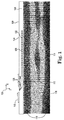
- Figure 1 illustrates an elevation or xz-plane 130 view of marine surveying in which an electric current is injected into a fluid volume 108 a dipole source 126 for recording by electromagnetic receivers 122.
- Processing and analysis of data from injecting the electric current can be performed in order to help characterize the structures and distributions of features and materials underlying the surface of the earth. For example, such processing can include generating a resistivity profile directly from measured EM field data as described herein.
- FIG 1 shows an example of a marine survey vessel 118 equipped to carry out marine surveys.
- the marine survey vessel 118 can tow one or more streamers 120 (shown as one streamer for ease of illustration) generally located below the sea surface 109.
- the streamers 120 can be long cables containing power and data-transmission lines, such as electrical, optical fiber, etc., to which receivers may be coupled.
- each receiver such as receiver 122, comprises an electromagnetic receiver that detects electromagnetic energy within the water.
- receivers on one or more streamers 120, such as receiver 122 can be a combination of electromagnetic receivers and seismic receives, such as hydrophones or geophone sensors, such that one or more streamers 120 can be used in both electromagnetic surveys and seismic surveys.
- the streamers 120 and the marine survey vessel 118 can include sensing electronics and data-processing facilities that allow receiver readings to be correlated with absolute positions on the sea surface and absolute three-dimensional positions with respect to a three-dimensional coordinate system.
- the receivers along the streamers are shown to lie below the sea surface 109, with the receiver positions correlated with overlying surface positions, such as a surface position 124 correlated with the position of receiver 122.
- the marine survey vessel 118 can also tow one or more sources 126 that produce signals as the marine survey vessel 118 and streamers 120 move across the sea surface 109. Sources 126 and/or streamers 120 may also be towed by other vessels, or may be otherwise disposed in fluid volume 108.
- receivers may be located on ocean bottom cables or nodes fixed at or near the surface 109, and sources 126 may also be disposed in a nearly-fixed or fixed configuration.
- Figure 1 shows the energy flux 112 and 116 (displayed as arrows) resulting from the electric current injected by the dipole source 126 and a subsurface resistivity profile 110 from an inversion (indicated by the shading).
- a change in the resistivity profile may indicate a change in the geology of the subsurface. For example, the darker shading 114 surrounded by lighter shading may be indicative of hydrocarbons in the subsurface.
- a purpose of Controlled Source ElectroMagnetics may be to estimate the subsurface resistivity from measured EM field data.
- the resistivity may be obtained by utilizing an inversion algorithm.
- the measured EM field data may be compared with modeled EM field data given a resistivity model in an iterative procedure. For example, an objective function may be iteratively minimized until the measured and modeled data difference is lower than a threshold value.
- iterative algorithms to minimize the objective function include, but are not limited to, a regularized Gauss-Newton and various types of conjugate gradient methods. Such algorithms may be time consuming when an inversion algorithm is used for large sub-surface domains where a large amount of data is included.
- a long survey line 100 kilometers (km) long may take many hours to invert when using a parallelized 2.5-dimensional inversion code.
- the computation time may be even greater for a 3-dimensional inversion of large subsurface domains.
- a 100 km by 70 km survey area may take many days on a computer cluster with several hundred processors.
- the inversion results as a consequence of high spatial data density from a receiver such as a towed sensor cable (streamer) or ocean-bottom cable EM survey, may have high resolution and may be of good quality.
- a disadvantage may be extensive computational time that may be required. Inversions may also suffer from non-uniqueness and may be ill posed. An inversion may lead to an objective function that is minimized to have several minima.
- a resistivity profile for a subsurface domain can be determined directly from measured EM field data from a marine survey, without the utilization of an inversion algorithm.
- a resistivity profile for a source position (or "shot points") in a source array of source positions can be determined directly from measured EM field data from a marine survey, without the utilization of an inversion algorithm.
- a resistivity profile in depth can be generated from an explicit expression, which can be derived from a series of transformations of measured EM field data.
- the method can include a Hankel transformation of the measured EM field data resulting in an ordinary differential equation (ODE) with a boundary condition at a measurement point such as a measurement point along a towed streamer or an ocean-bottom cable.
- ODE ordinary differential equation
- a boundary condition can be a constraint used in solving a boundary value problem (BVP).
- BVP boundary value problem
- the BVP can be a differential equation together with one or more boundary conditions.
- the solution of this ODE is dependent on the resistivity profile.
- a second transformation can be applied to the ODE resulting in an integro-differential equation with a solution that is no longer dependent on the resistivity
- ⁇ z i ⁇ 0 ⁇ ⁇ ⁇ ⁇ 2 q z ⁇ ⁇ z d ⁇ ⁇ ⁇ ⁇ ⁇ ⁇ ⁇ q z ⁇ ⁇ z d ⁇ 2 ⁇ 1
- p(z) is the marine environment resistivity as a function of the depth z below a receiver
- ⁇ is the angular frequency of a source
- q(Z,T) is an EM field transformation function of the depth z and the angular frequency w (see expression (8) discussed below)
- ⁇ 0 is the magnetic permeability of the marine environment
- i is the imaginary unit.
- Expression (1) can be used to generate a resistivity profile
- the dipole source can be a pair of electrodes used to inject an electric current into a body of water.
- the electric current may interact with the structure of the marine survey equipment, which may include a marine vessel and a towed streamer. The interaction may affect an electric potential measurement.
- in-line refers to a field component that is tangent to a source and a receiver.
- ⁇ 0 is the Hankel transformation shown in expression (6).
- the boundary conditions are a measurement point at a receiver (depth z is 0) and the radiation condition at the subsurface (depth z is L).
- This BVP can be solved if the conductivity, which is the inverse of the resistivity, is known. However, the conductivity is often unknown and in some instances can be estimated through inversion.
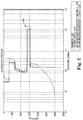
- At least one embodiment of the present disclosure can result in resistivity profiles from expression (1) for two different values of ⁇ (L) as shown in Figure 2.
- Figure 2 shows estimated 1 D resistivity profiles from an inversion (profile 232) and from solving BVP (12) and using expression (1) according to at least one embodiment of the present disclosure with two different values of the background resistivity: 1000 ⁇ (profile 236) and 2 ⁇ (profile 238).
- a "true" profile is also shown (profile 234).
- the "true” profile is the assumed correct profile for the purpose of comparing the accuracy of various computational methods of arriving at a profile.
- the source was placed 10 m below the sea-surface and the receiver points along the streamer at a 100 meters (m) depth.
- the frequencies ranged from 0.1 - 5 Hz and the offsets, the distance between a source and a receiver, reached from 1000 m to 6000 m.
- Figure 2 shows estimated 1 D resistivity profiles from an inversion and from solving a BVP according to at least one embodiment of the present disclosure with two different values of background resistivity.
- resistivity profiles 236 and 238 generated from expression (1) can agree with a "true" profile 234 as well as a profile 232 generated from an inversion.
- Seawater has a relatively low resistivity compared to that of hydrocarbons.
- Variation in the overburden, the region above the resistive anomaly can also be captured including situations with a high resistive anomaly (refer to 240 in Figure 2 ).
- Such a high resistive anomaly can be indicative of hydrocarbons in a subsurface.
- the expression (1) can be used to recover or estimate the resistivity in the subsurface from towed streamer and ocean-bottom cable EM field data.
- the conductivity value ⁇ (L) can be chosen according to expected geology.
- Figure 3 illustrates a diagram of a system 362 for generating a resistivity profile for a source directly from measured EM field data from a marine survey.
- the system 362 can include a data store 366, a subsystem 364, and/or a number of engines, such as a transformation engine 368 and/or a boundary engine 370, and the subsystem 364 and engines can be in communication with the data store 366 via a communication link.
- the system 362 can include additional or fewer engines than illustrated to perform the various functions described herein.
- the system can represent program instructions and/or hardware of a machine such as the machine 474 referenced in Figure 4 , etc.
- an "engine” can include program instructions and/or hardware, but at least includes hardware.
- Hardware is a physical component of a machine that enables it to perform a function. Examples of hardware can include a processing resource, a memory resource, a logic gate, etc.
- the number of engines can include a combination of hardware and program instructions that is configured to perform a number of functions described herein.
- the program instructions such as software, firmware, etc., can be stored in a memory resource such as a machine-readable medium, etc., as well as hard-wired program such as logic. Hard-wired program instructions can be considered as both program instructions and hardware.
- the transformation engine 368 can include a combination of hardware and program instructions that is configured to apply a series of transformations to a measured EM field data to yield a BVP.
- the series of transformations can include a zero-order Hankel transformation and a transformation to remove a conductivity dependency.
- the series of transformations can be applied to an x-component of the measured EM field data, where "x" is a sailing direction.
- the x-component can be in-line with the at least one source and a towed sensor cable.
- the measurement point can be on a towed sensor cable or an ocean-bottom cable.
- the at least one source can comprise a pair of electrodes forming a dipole source.
- the boundary engine 370 can include a combination of hardware and program instructions that is configured to determine a first boundary condition based on at least one of the series of transformations of the measured EM field data and a measurement point, apply the first boundary condition to the BVP, discretize a second boundary condition in depth and frequency, and solve the BVP according to the first and the second boundary conditions to generate a resistivity profile for at least one source.
- the measurement point can be on a towed sensor cable or an ocean-bottom cable.
- a source can be a pair of electrodes comprising a dipole source.
- the system 362 can also include the profile engine.
- the profile engine can include a combination of hardware and program instructions that is configured to receive solutions to the BVP at a plurality of measurement points and generate a resistivity profile for a surveyed area.
- Figure 4 illustrates a diagram of a machine 474 for generating a resistivity profile for a source directly from measured EM field data from a marine survey.
- the machine 474 can utilize software, hardware, firmware, and/or logic to perform a number of functions.
- the machine 474 can be a combination of hardware and program instructions configured to perform a number of functions and/or actions.
- the hardware for example, can include a number of processing resources 476 and a number of memory resources 478, such as a machine-readable medium or other non-transitory memory resources 478.
- the memory resources 478 can be internal and/or external to the machine 474, for example, the machine 474 can include internal memory resources and have access to external memory resources.
- the program instructions can include instructions stored on the machine-readable medium to implement a particular function, for example, an action such as generating a resistivity profile for a source directly from measured EM field data from a marine survey.
- the set of machine-readable instructions can be executable by one or more of the processing resources 476.
- the memory resources 478 can be coupled to the machine 474 in a wired and/or wireless manner.
- the memory resources 478 can be an internal memory, a portable memory, a portable disk, and/or a memory associated with another resource, for example, enabling machine-readable instructions to be transferred and/or executed across a network such as the Internet.
- a "module" can include program instructions and/or hardware, but at least includes program instructions.
- Memory resources 478 can be non-transitory and can include volatile and/or non-volatile memory.
- Volatile memory can include memory that depends upon power to store information, such as various types of dynamic random access memory among others.
- Non-volatile memory can include memory that does not depend upon power to store information. Examples of non-volatile memory can include solid state media such as flash memory, electrically erasable programmable read-only memory, phase change random access memory, magnetic memory, optical memory, and/or a solid state drive, etc., as well as other types of non-transitory machine-readable media.
- the processing resources 476 can be coupled to the memory resources 478 via a communication path 480.
- the communication path 480 can be local or remote to the machine 474. Examples of a local communication path 480 can include an electronic bus internal to a machine, where the memory resources 478 are in communication with the processing resources 476 via the electronic bus. Examples of such electronic buses can include Industry Standard Architecture, Peripheral Component Interconnect, Advanced Technology Attachment, Small Computer System Interface, Universal Serial Bus, among other types of electronic buses and variants thereof.
- the communication path 480 can be such that the memory resources 478 are remote from the processing resources 476, such as in a network connection between the memory resources 478 and the processing resources 476. That is, the communication path 480 can be a network connection. Examples of such a network connection can include a local area network, wide area network, personal area network, and the Internet, among others.
- the machine-readable instructions stored in the memory resources 478 can be segmented into a number of modules 482 and 484 that when executed by the processing resources 476 can perform a number of functions.
- a module includes a set of instructions included to perform a particular task or action.
- the number of modules 482 and 484 can be sub-modules of other modules.
- the boundary module 484 can be a sub-module of the transformation module 482 and/or the boundary module 484 and the transformation module 482 can be contained within a single module.
- the number of modules 482 and 484 can comprise individual modules separate and distinct from one another. Examples are not limited to the specific modules 482 and 484 illustrated in Figure 4 .
- Each of the number of modules 482 and 484 can include program instructions and/or a combination of hardware and program instructions that, when executed by a processing resource 476, can function as a corresponding engine as described with respect to Figure 3 .
- the transformation module 482 can include program instructions and/or a combination of hardware and program instructions that, when executed by a processing resource 476, can function as the transformation engine 368
- the boundary module 484 can include program instructions and/or a combination of hardware and program instructions that, when executed by a processing resource 476, can function as the boundary engine 370 and/or profile engine.
- the machine 474 can include a transformation module 482, which can include instructions to transform a vector potential of measured EM field data.
- the transformation module 482 can also include instructions to transform a first BVP.
- the transformation module can also include instructions for a series of transformations.
- the instructions to transform the first BVP can include instructions to remove a conductivity dependency.
- the instructions to estimate the boundary value for the given conductivity can include instructions to use a Hankel transform variable equal to zero, where the given conductivity can be a known conductivity of seawater and a conductivity of a subsurface.
- the machine 474 can include a boundary module 484, which can include instructions to obtain a first BVP, obtain a second BVP, estimate a boundary value for a given conductivity, discretize the second BVP in distance in depth below a below a water surface and frequency, and generate a resistivity profile according to an explicit expression using the estimated boundary value.
- the given conductivity can be known conductivity of seawater and/or a subsurface. Generating the resistivity profile according to the explicit expression using the estimated boundary value can comprise a non-iterative computational modeling process.
- the instructions to obtain the first BVP can include instructions to obtain an ordinary differential equation and/or an integro-differential equation.
- the instructions to obtain the first BVP can also include instructions to estimate a conductivity of a marine environment as a function of depth only.
- a geophysical data product may be produced.
- the geophysical data product may include, for example, a marine survey measurement with an estimated acquisition effect removed therefrom.
- Geophysical data may be obtained and stored on a non-transitory, tangible computer-readable medium.
- the geophysical data product may be produced by processing the geophysical data offshore or onshore either within the United States or in another country. If the geophysical data product is produced offshore or in another country, it may be imported onshore to a facility in the United States. In some instances, once onshore in the United States, geophysical analysis may be performed on the geophysical data product. In some instances, geophysical analysis may be performed on the geophysical data product offshore.
- a series of transformations can be applied to measured EM field data to yield a BVP
- a first boundary condition can be determined based on at least one of the series of transformations of the measured EM field data and a measurement point
- the first boundary condition can then be applied to the BVP
- a second boundary condition in depth and frequency can be discretized
- a resistivity profile can be generated for at least one source by solving the BVP according to the first and the second boundary conditions.
- the resistivity profile can be generated directly from measured EM field data offshore to facilitate other processing of the acquired marine survey measurement either offshore or onshore.
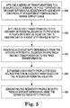
- Figure 5 illustrates a method flow diagram for generating a resistivity profile for a source directly from measured EM field data from a marine survey.
- the method can include applying a series of transformations to measured EM field data to provide an ordinary differential equation with boundary conditions at measurement points along a marine survey cable. The measurement points can be offset from each source position.
- the method can include applying a first transformation to the ordinary differential equation to provide an integro-differential equation that is independent of a resistivity profile in depth.
- the method can include removing a conductivity dependency from the integro-differential equation by applying a second transformation to the first transformation.
- Applying the second transformation can include rewriting the first transformation as a function of the second transformation.
- Removing the conductivity dependency from the integro-differential equation by applying the second transformation to the first transformation can comprise a non-iterative computational modeling process.
- the method can include estimating a resistivity profile for each source position in a source array based on the integro-differential equation.
- the method can include generating the resistivity profile in depth from an explicit expression using the estimated resistivity profiles.
- Generating the resistivity profile can include integrating the measured electric field data along the marine survey cable, and obtaining a boundary value from a model with a known seawater conductivity and an estimated subsurface conductivity.
Landscapes
- Physics & Mathematics (AREA)
- Life Sciences & Earth Sciences (AREA)
- Remote Sensing (AREA)
- Engineering & Computer Science (AREA)
- Electromagnetism (AREA)
- Environmental & Geological Engineering (AREA)
- Geology (AREA)
- General Life Sciences & Earth Sciences (AREA)
- General Physics & Mathematics (AREA)
- Geophysics (AREA)
- Oceanography (AREA)
- Acoustics & Sound (AREA)
- Investigating Or Analyzing Materials By The Use Of Electric Means (AREA)
- Geophysics And Detection Of Objects (AREA)
- Measurement Of Resistance Or Impedance (AREA)
Abstract
Description
- In the past few decades, the petroleum industry has invested heavily in the development of marine survey techniques that yield knowledge of subterranean formations beneath a body of water in order to find and extract valuable mineral resources, such as oil. High-resolution images of a subterranean formation are helpful for quantitative interpretation and improved reservoir monitoring. For a typical marine survey, a marine survey vessel tows one or more sources below the sea surface and over a subterranean formation to be surveyed for mineral deposits. Receivers may be located on or near the seafloor, on one or more streamers towed by the marine survey vessel, or on one or more streamers towed by another vessel. The marine survey vessel typically contains marine survey equipment, such as navigation control, source control, receiver control, and recording equipment. The source control may cause the one or more sources, which can be air guns, marine vibrators, electromagnetic sources, etc., to produce signals at selected times. Each signal is essentially a wave called a wavefield that travels down through the water and into the subterranean formation. At each interface between different types of rock, a portion of the wavefield may be refracted, and another portion may be reflected, which may include some scattering, back toward the body of water to propagate toward the sea surface. The receivers thereby measure a wavefield that was initiated by the actuation of the source.
-
-
Figure 1 illustrates an elevation or xz-plane view of marine surveying in which an electric current is injected into a fluid volume by a dipole source for recording by electromagnetic receivers. -
Figure 2 shows estimated 1 D resistivity profiles from an inversion and from solving a boundary value problem according to at least one embodiment of the present disclosure with two different values of background resistivity. -
Figure 3 illustrates a diagram of a system for generating a resistivity profile for a source directly from measured electromagnetic field data from a marine survey. -
Figure 4 illustrates a diagram of a machine for generating a resistivity profile for a source directly from measured electromagnetic field data from a marine survey. -
Figure 5 illustrates a method flow diagram for generating a resistivity profile for a source directly from measured electromagnetic field data from a marine survey. - The present disclosure is related to generating a resistivity profile directly from measured electromagnetic (EM) field data. The measured EM field data can be acquired from a measured EM field. Some methods for generating a resistivity profile may require an iterative computation modeling process, such as an inversion. This iterative process may take many hours to yield a resistivity profile. It would be advantageous if a resistivity profile could be generated directly from measured EM field data using a non-iterative computation modeling process, such as an inversion. At least one embodiment of the present disclosure can generate a resistivity profile directly from measured EM field data using a non-iterative computation modeling process. That is, an inversion may not be required. In at least one instance, the resistivity profile can be generated by applying a series of transformations to the measured EM field data.
- It is to be understood the present disclosure is not limited to particular devices or methods, which may, of course, vary. It is also to be understood that the terminology used herein is for the purpose of describing particular embodiments only, and is not intended to be limiting. As used herein, the singular forms "a", "an", and "the" include singular and plural referents unless the content clearly dictates otherwise. Furthermore, the word "may" is used throughout this application in a permissive sense (i.e., having the potential to, being able to), not in a mandatory sense (i.e., must). The term "include," and derivations thereof, mean "including, but not limited to." The term "coupled" means directly or indirectly connected.
- The figures herein follow a numbering convention in which the first digit or digits correspond to the drawing figure number and the remaining digits identify an element or component in the drawing. Similar elements or components between different figures may be identified by the use of similar digits. As will be appreciated, elements shown in the various embodiments herein can be added, exchanged, and/or eliminated so as to provide a number of additional embodiments of the present disclosure. In addition, as will be appreciated, the proportion and the relative scale of the elements provided in the figures are intended to illustrate certain embodiments of the present invention, and should not be taken in a limiting sense.
-
Figure 1 illustrates an elevation or xz-plane 130 view of marine surveying in which an electric current is injected into a fluid volume 108 adipole source 126 for recording byelectromagnetic receivers 122. Processing and analysis of data from injecting the electric current can be performed in order to help characterize the structures and distributions of features and materials underlying the surface of the earth. For example, such processing can include generating a resistivity profile directly from measured EM field data as described herein. -
Figure 1 shows an example of amarine survey vessel 118 equipped to carry out marine surveys. In particular, themarine survey vessel 118 can tow one or more streamers 120 (shown as one streamer for ease of illustration) generally located below thesea surface 109. Thestreamers 120 can be long cables containing power and data-transmission lines, such as electrical, optical fiber, etc., to which receivers may be coupled. In one type of marine survey, each receiver, such asreceiver 122, comprises an electromagnetic receiver that detects electromagnetic energy within the water. In another type of marine survey, receivers on one ormore streamers 120, such asreceiver 122, can be a combination of electromagnetic receivers and seismic receives, such as hydrophones or geophone sensors, such that one ormore streamers 120 can be used in both electromagnetic surveys and seismic surveys. Thestreamers 120 and themarine survey vessel 118 can include sensing electronics and data-processing facilities that allow receiver readings to be correlated with absolute positions on the sea surface and absolute three-dimensional positions with respect to a three-dimensional coordinate system. InFigure 1 , the receivers along the streamers are shown to lie below thesea surface 109, with the receiver positions correlated with overlying surface positions, such as asurface position 124 correlated with the position ofreceiver 122. Themarine survey vessel 118 can also tow one ormore sources 126 that produce signals as themarine survey vessel 118 andstreamers 120 move across thesea surface 109.Sources 126 and/orstreamers 120 may also be towed by other vessels, or may be otherwise disposed influid volume 108. For example, receivers may be located on ocean bottom cables or nodes fixed at or near thesurface 109, andsources 126 may also be disposed in a nearly-fixed or fixed configuration. -
Figure 1 shows theenergy flux 112 and 116 (displayed as arrows) resulting from the electric current injected by thedipole source 126 and asubsurface resistivity profile 110 from an inversion (indicated by the shading). A change in the resistivity profile may indicate a change in the geology of the subsurface. For example, thedarker shading 114 surrounded by lighter shading may be indicative of hydrocarbons in the subsurface. - A purpose of Controlled Source ElectroMagnetics (CSEM) may be to estimate the subsurface resistivity from measured EM field data. In some instances, the resistivity may be obtained by utilizing an inversion algorithm. The measured EM field data may be compared with modeled EM field data given a resistivity model in an iterative procedure. For example, an objective function may be iteratively minimized until the measured and modeled data difference is lower than a threshold value. Some examples of iterative algorithms to minimize the objective function include, but are not limited to, a regularized Gauss-Newton and various types of conjugate gradient methods. Such algorithms may be time consuming when an inversion algorithm is used for large sub-surface domains where a large amount of data is included. For example, a long survey line 100 kilometers (km) long may take many hours to invert when using a parallelized 2.5-dimensional inversion code. The computation time may be even greater for a 3-dimensional inversion of large subsurface domains. For example, a 100 km by 70 km survey area may take many days on a computer cluster with several hundred processors. The inversion results, as a consequence of high spatial data density from a receiver such as a towed sensor cable (streamer) or ocean-bottom cable EM survey, may have high resolution and may be of good quality. However, a disadvantage may be extensive computational time that may be required. Inversions may also suffer from non-uniqueness and may be ill posed. An inversion may lead to an objective function that is minimized to have several minima. Multiple inversion results may yield the same good match between modeled and measured EM data. An ill posed inversion may refer to an inversion that is unstable and may ultimately crash or fail. Therefore, it may be necessary to regularize the objective function in order to stabilize the minimization. Therefore, it can be useful to regularize the minimization algorithm to obtain a stable solution. The solution can vary with the type of regularization as well as the minimization method itself. According to at least one embodiment of the present disclosure, a resistivity profile for a subsurface domain can be determined directly from measured EM field data from a marine survey, without the utilization of an inversion algorithm.
- According to at least one embodiment of the present disclosure, a resistivity profile for a source position (or "shot points") in a source array of source positions can be determined directly from measured EM field data from a marine survey, without the utilization of an inversion algorithm. A resistivity profile in depth can be generated from an explicit expression, which can be derived from a series of transformations of measured EM field data. The method can include a Hankel transformation of the measured EM field data resulting in an ordinary differential equation (ODE) with a boundary condition at a measurement point such as a measurement point along a towed streamer or an ocean-bottom cable. A boundary condition can be a constraint used in solving a boundary value problem (BVP). The BVP can be a differential equation together with one or more boundary conditions. The solution of this ODE is dependent on the resistivity profile. However, a second transformation can be applied to the ODE resulting in an integro-differential equation with a solution that is no longer dependent on the resistivity profile.
- An explicit expression for determining a resistivity profile for a source directly from measured EM field data can be derived to:

- Expression (1) can be derived by starting from a vector potential A = (Ax,0,Az) for a horizontal electric current dipole source in the x-direction (the horizontal direction in-line with the dipole source). The dipole source can be a pair of electrodes used to inject an electric current into a body of water. The electric current may interact with the structure of the marine survey equipment, which may include a marine vessel and a towed streamer. The interaction may affect an electric potential measurement. As will be appreciated by one of ordinary skill in the art, in-line refers to a field component that is tangent to a source and a receiver. In a conductive medium and at frequencies used in CSEM, the vector potential is approximately given by:


Figure 1 (the y-direction is into and out of the page) and σ(r) is the conductivity of the marine environment as a function of the position vector r. - Taking the zero-order cylindrical Hankel transformation u of the x-component of the vector potential yields:


- To remove the conductivity dependency from BVP (7), which consists of expressions (7a), (7b), and (7c), a second transform can be applied:


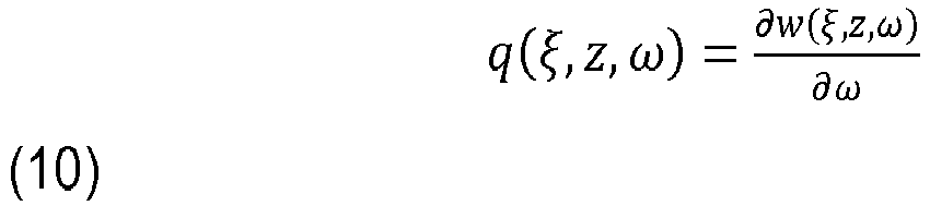

- Inserting expression (11) into expression (7a) results in expression (1), an expression for calculating a resistivity directly from measured EM field data without utilizing an inversion method. As a result of the transformation in expression (11), BVP (7) becomes:


L 

σ = σ(L) in the subsurface To solve BVP (12), which consists of expressions (12a), (12b), (12c), (12d), and (12e), and obtain a boundary value, the derivatives can be estimated for a given conductivity σ(L) and then the integro-differential equation can be discretized in both z and w. A solution to BVP (12) can be independent of σ(L) for a large depth L, which can be 3 km below the seafloor. - At least one embodiment of the present disclosure can result in resistivity profiles from expression (1) for two different values of σ(L) as shown in
Figure 2. Figure 2 shows estimated 1 D resistivity profiles from an inversion (profile 232) and from solving BVP (12) and using expression (1) according to at least one embodiment of the present disclosure with two different values of the background resistivity: 1000 Ω (profile 236) and 2 Ω (profile 238). A "true" profile is also shown (profile 234). The "true" profile is the assumed correct profile for the purpose of comparing the accuracy of various computational methods of arriving at a profile. In the example ofFigure 2 , the source was placed 10 m below the sea-surface and the receiver points along the streamer at a 100 meters (m) depth. The frequencies ranged from 0.1 - 5 Hz and the offsets, the distance between a source and a receiver, reached from 1000 m to 6000 m. -
Figure 2 shows estimated 1 D resistivity profiles from an inversion and from solving a BVP according to at least one embodiment of the present disclosure with two different values of background resistivity. As shown inFigure 2 ,resistivity profiles profile 232 generated from an inversion. Seawater has a relatively low resistivity compared to that of hydrocarbons. Variation in the overburden, the region above the resistive anomaly, can also be captured including situations with a high resistive anomaly (refer to 240 inFigure 2 ). Such a high resistive anomaly can be indicative of hydrocarbons in a subsurface. The expression (1) can be used to recover or estimate the resistivity in the subsurface from towed streamer and ocean-bottom cable EM field data. The conductivity value σ(L) can be chosen according to expected geology. -
Figure 3 illustrates a diagram of asystem 362 for generating a resistivity profile for a source directly from measured EM field data from a marine survey. Thesystem 362 can include adata store 366, asubsystem 364, and/or a number of engines, such as atransformation engine 368 and/or aboundary engine 370, and thesubsystem 364 and engines can be in communication with thedata store 366 via a communication link. Thesystem 362 can include additional or fewer engines than illustrated to perform the various functions described herein. The system can represent program instructions and/or hardware of a machine such as themachine 474 referenced inFigure 4 , etc. As used herein, an "engine" can include program instructions and/or hardware, but at least includes hardware. Hardware is a physical component of a machine that enables it to perform a function. Examples of hardware can include a processing resource, a memory resource, a logic gate, etc. - The number of engines can include a combination of hardware and program instructions that is configured to perform a number of functions described herein. The program instructions, such as software, firmware, etc., can be stored in a memory resource such as a machine-readable medium, etc., as well as hard-wired program such as logic. Hard-wired program instructions can be considered as both program instructions and hardware.
- The
transformation engine 368 can include a combination of hardware and program instructions that is configured to apply a series of transformations to a measured EM field data to yield a BVP. The series of transformations can include a zero-order Hankel transformation and a transformation to remove a conductivity dependency. The series of transformations can be applied to an x-component of the measured EM field data, where "x" is a sailing direction. The x-component can be in-line with the at least one source and a towed sensor cable. The measurement point can be on a towed sensor cable or an ocean-bottom cable. The at least one source can comprise a pair of electrodes forming a dipole source. - The
boundary engine 370 can include a combination of hardware and program instructions that is configured to determine a first boundary condition based on at least one of the series of transformations of the measured EM field data and a measurement point, apply the first boundary condition to the BVP, discretize a second boundary condition in depth and frequency, and solve the BVP according to the first and the second boundary conditions to generate a resistivity profile for at least one source. The measurement point can be on a towed sensor cable or an ocean-bottom cable. A source can be a pair of electrodes comprising a dipole source. - In at least one embodiment, the
system 362 can also include the profile engine. The profile engine can include a combination of hardware and program instructions that is configured to receive solutions to the BVP at a plurality of measurement points and generate a resistivity profile for a surveyed area. -
Figure 4 illustrates a diagram of amachine 474 for generating a resistivity profile for a source directly from measured EM field data from a marine survey. Themachine 474 can utilize software, hardware, firmware, and/or logic to perform a number of functions. Themachine 474 can be a combination of hardware and program instructions configured to perform a number of functions and/or actions. The hardware, for example, can include a number ofprocessing resources 476 and a number ofmemory resources 478, such as a machine-readable medium or othernon-transitory memory resources 478. Thememory resources 478 can be internal and/or external to themachine 474, for example, themachine 474 can include internal memory resources and have access to external memory resources. The program instructions, such as machine-readable instructions, can include instructions stored on the machine-readable medium to implement a particular function, for example, an action such as generating a resistivity profile for a source directly from measured EM field data from a marine survey. The set of machine-readable instructions can be executable by one or more of theprocessing resources 476. Thememory resources 478 can be coupled to themachine 474 in a wired and/or wireless manner. For example, thememory resources 478 can be an internal memory, a portable memory, a portable disk, and/or a memory associated with another resource, for example, enabling machine-readable instructions to be transferred and/or executed across a network such as the Internet. As used herein, a "module" can include program instructions and/or hardware, but at least includes program instructions. -
Memory resources 478 can be non-transitory and can include volatile and/or non-volatile memory. Volatile memory can include memory that depends upon power to store information, such as various types of dynamic random access memory among others. Non-volatile memory can include memory that does not depend upon power to store information. Examples of non-volatile memory can include solid state media such as flash memory, electrically erasable programmable read-only memory, phase change random access memory, magnetic memory, optical memory, and/or a solid state drive, etc., as well as other types of non-transitory machine-readable media. - The
processing resources 476 can be coupled to thememory resources 478 via acommunication path 480. Thecommunication path 480 can be local or remote to themachine 474. Examples of alocal communication path 480 can include an electronic bus internal to a machine, where thememory resources 478 are in communication with theprocessing resources 476 via the electronic bus. Examples of such electronic buses can include Industry Standard Architecture, Peripheral Component Interconnect, Advanced Technology Attachment, Small Computer System Interface, Universal Serial Bus, among other types of electronic buses and variants thereof. Thecommunication path 480 can be such that thememory resources 478 are remote from theprocessing resources 476, such as in a network connection between thememory resources 478 and theprocessing resources 476. That is, thecommunication path 480 can be a network connection. Examples of such a network connection can include a local area network, wide area network, personal area network, and the Internet, among others. - As shown in
Figure 4 , the machine-readable instructions stored in thememory resources 478 can be segmented into a number ofmodules processing resources 476 can perform a number of functions. As used herein a module includes a set of instructions included to perform a particular task or action. The number ofmodules boundary module 484 can be a sub-module of thetransformation module 482 and/or theboundary module 484 and thetransformation module 482 can be contained within a single module. Furthermore, the number ofmodules specific modules Figure 4 . - Each of the number of
modules processing resource 476, can function as a corresponding engine as described with respect toFigure 3 . For example, thetransformation module 482 can include program instructions and/or a combination of hardware and program instructions that, when executed by aprocessing resource 476, can function as thetransformation engine 368, and/or theboundary module 484 can include program instructions and/or a combination of hardware and program instructions that, when executed by aprocessing resource 476, can function as theboundary engine 370 and/or profile engine. - The
machine 474 can include atransformation module 482, which can include instructions to transform a vector potential of measured EM field data. Thetransformation module 482 can also include instructions to transform a first BVP. The transformation module can also include instructions for a series of transformations. The instructions to transform the first BVP can include instructions to remove a conductivity dependency. The instructions to estimate the boundary value for the given conductivity can include instructions to use a Hankel transform variable equal to zero, where the given conductivity can be a known conductivity of seawater and a conductivity of a subsurface. - The
machine 474 can include aboundary module 484, which can include instructions to obtain a first BVP, obtain a second BVP, estimate a boundary value for a given conductivity, discretize the second BVP in distance in depth below a below a water surface and frequency, and generate a resistivity profile according to an explicit expression using the estimated boundary value. The given conductivity can be known conductivity of seawater and/or a subsurface. Generating the resistivity profile according to the explicit expression using the estimated boundary value can comprise a non-iterative computational modeling process. The instructions to obtain the first BVP can include instructions to obtain an ordinary differential equation and/or an integro-differential equation. The instructions to obtain the first BVP can also include instructions to estimate a conductivity of a marine environment as a function of depth only. - In accordance with a number of embodiments of the present disclosure, a geophysical data product may be produced. The geophysical data product may include, for example, a marine survey measurement with an estimated acquisition effect removed therefrom. Geophysical data may be obtained and stored on a non-transitory, tangible computer-readable medium. The geophysical data product may be produced by processing the geophysical data offshore or onshore either within the United States or in another country. If the geophysical data product is produced offshore or in another country, it may be imported onshore to a facility in the United States. In some instances, once onshore in the United States, geophysical analysis may be performed on the geophysical data product. In some instances, geophysical analysis may be performed on the geophysical data product offshore. For example, a series of transformations can be applied to measured EM field data to yield a BVP, a first boundary condition can be determined based on at least one of the series of transformations of the measured EM field data and a measurement point, the first boundary condition can then be applied to the BVP, a second boundary condition in depth and frequency can be discretized, and then a resistivity profile can be generated for at least one source by solving the BVP according to the first and the second boundary conditions. As another example, the resistivity profile can be generated directly from measured EM field data offshore to facilitate other processing of the acquired marine survey measurement either offshore or onshore.
-
Figure 5 illustrates a method flow diagram for generating a resistivity profile for a source directly from measured EM field data from a marine survey. Atblock 588, the method can include applying a series of transformations to measured EM field data to provide an ordinary differential equation with boundary conditions at measurement points along a marine survey cable. The measurement points can be offset from each source position. - At
block 590, the method can include applying a first transformation to the ordinary differential equation to provide an integro-differential equation that is independent of a resistivity profile in depth. - At
block 592, the method can include removing a conductivity dependency from the integro-differential equation by applying a second transformation to the first transformation. Applying the second transformation can include rewriting the first transformation as a function of the second transformation. Removing the conductivity dependency from the integro-differential equation by applying the second transformation to the first transformation can comprise a non-iterative computational modeling process. - At
block 594, the method can include estimating a resistivity profile for each source position in a source array based on the integro-differential equation. - At
block 596, the method can include generating the resistivity profile in depth from an explicit expression using the estimated resistivity profiles. Generating the resistivity profile can include integrating the measured electric field data along the marine survey cable, and obtaining a boundary value from a model with a known seawater conductivity and an estimated subsurface conductivity. - Although specific embodiments have been described above, these embodiments are not intended to limit the scope of the present disclosure, even where only a single embodiment is described with respect to a particular feature. Examples of features provided in the disclosure are intended to be illustrative rather than restrictive unless stated otherwise. The above description is intended to cover such alternatives, modifications, and equivalents as would be apparent to a person skilled in the art having the benefit of this disclosure.
- The scope of the present disclosure includes any feature or combination of features disclosed herein (either explicitly or implicitly), or any generalization thereof, whether or not it mitigates any or all of the problems addressed herein. Various advantages of the present disclosure have been described herein, but embodiments may provide some, all, or none of such advantages, or may provide other advantages.
- In the foregoing Detailed Description, some features are grouped together in a single embodiment for the purpose of streamlining the disclosure. This method of disclosure is not to be interpreted as reflecting an intention that the disclosed embodiments of the present disclosure have to use more features than are expressly recited in each claim. Rather, as the following claims reflect, inventive subject matter lies in less than all features of a single disclosed embodiment. Thus, the following claims are hereby incorporated into the Detailed Description, with each claim standing on its own as a separate embodiment.
Claims (22)
- A system, comprising:measured electromagnetic (EM) field data from a marine survey;a transformation engine configured to apply a series of transformations to the measured EM field data to yield a boundary value problem (BVP); anda boundary engine configured to:determine a first boundary condition based on at least one of the series of transformations of the measured EM field data and a measurement point;apply the first boundary condition to the boundary value problem;discretize a second boundary condition in depth and frequency; andsolve the BVP according to the first boundary condition and the second discretized boundary condition to generate a resistivity profile for at least one source.
- The system of claim 1, wherein the series of transformations comprise:applying a zero order Hankel transformation to a vector potential of the measured EM field data; andapplying a second transformation to the zero order Hankel transformation of the vector potential of the measured EM field data.
- The system of claim 1, wherein the series of transformations comprise:applying a zero-order Hankel transformation to an x-component of a vector potential of the measured EM field data; andapplying a second transformation to the zero-order Hankel transformation of the x-component of the vector potential of the measured EM field data; and optionally wherein the x-component of the vector potential of the measured EM field data is in-line with the at least one source and a towed sensor cable.
- The system of any of the preceding claims, wherein the measurement point is on a towed sensor cable or an ocean-bottom cable.
- The system of any of the preceding claims, wherein the at least one source comprises a pair of electrodes forming a dipole source.
- The system of claim 1, further comprising a profile engine configured to:receive solutions to the BVP at a plurality of measurement points; andgenerate a resistivity profile for a surveyed area.
- A non-transitory machine-readable medium storing instructions executable by a processing resource to:transform a vector potential of measured electromagnetic (EM) field data;obtain a first boundary value problem (BVP);transform the first BVP;obtain a second BVP;estimate a boundary value for a given conductivity;discretize the second BVP in depth below a water surface and frequency; andgenerate a resistivity profile according to an explicit expression using the estimated boundary value.
- The medium of claim 7, comprising instructions executable to generate the resistivity profile according to the explicit expression using the estimated boundary value comprises a non-iterative computation modeling process.
- The medium of claim 7, wherein the instructions executable to obtain the first BVP include instructions executable to obtain an ordinary differential equation.
- The medium of any of claims 7 to 9, wherein the instructions executable to obtain the second BVP include instructions executable to obtain an integro-differential equation.
- The medium of any of claims 7 to 10, wherein the instructions executable to obtain the first BVP include instructions executable to estimate a conductivity of a marine environment as a function of depth only.
- The medium of any of claims 7 to 11, wherein the instructions executable to transform the first BVP include instructions executable to remove a conductivity dependency.
- The medium of any of claims 7 to 12, wherein the instructions executable to estimate the boundary value for the given conductivity include instructions executable to use a Hankel transform variable equal to zero.
- The method of any of claims 7 to 13, wherein the given conductivity is a known conductivity of seawater and a conductivity of a subsurface.
- A method, comprising:applying a series of transformations to measured electromagnetic (EM) field data to provide an ordinary differential equation with boundary conditions at measurement points along a marine survey cable;applying a first transformation to the ordinary differential equation to provide an integro-differential equation that is independent of a resistivity profile in depth;removing a conductivity dependency from the integro-differential equation by applying a second transformation to the first transformation;estimating a resistivity profile for each source position in a source array based on the integro-differential equation; andgenerating the resistivity profile in depth from an explicit expression using the estimated resistivity profiles.
- The method of claim 15, wherein the measurement points are offset from each source position.
- The method of claim 15 or claim 16, wherein applying the second transformation includes rewriting the first transformation as a function of the second transformation.
- The method of any of claims 15 to 17, wherein generating the resistivity profile includes integrating the measured electric field data along the marine survey cable, and obtaining a boundary value from a model with a known seawater conductivity and an estimated subsurface conductivity.
- The method of any of claims 15 to 18, wherein removing the conductivity dependency from the integro-differential equation by applying the second transformation to the first transformation comprises a non-iterative computational modeling process.
- The method of any of claims 15 to 19, further comprising:injecting an electric current into a fluid volume; andrecording the measured EM field data with an EM receiver resulting from injecting the electric current.
- A method of generating a geophysical data product, the method comprising:obtaining geophysical data; andprocessing the geophysical data to generate the geophysical data product, wherein processing the geophysical data comprises:applying a series of transformations to measured electromagnetic (EM) field data to yield a boundary value problem (BVP);determining a first boundary condition based on at least one of the series of transformations of the measured EM field data and a measurement point;applying the first boundary condition to the BVP;discretizing a second boundary condition in depth and frequency; andsolving the BVP according to the first and the second boundary conditions to generate a resistivity profile for at least one source.
- The method of claim 21, further comprising recording the geophysical data product on a non-transitory machine-readable medium suitable for importing onshore and optionally wherein processing the geophysical data comprises processing the geophysical data offshore or onshore.
Applications Claiming Priority (2)
| Application Number | Priority Date | Filing Date | Title |
|---|---|---|---|
| US201562212234P | 2015-08-31 | 2015-08-31 | |
| US15/178,999 US10571592B2 (en) | 2015-08-31 | 2016-06-10 | Direct resistivity determination |
Publications (2)
| Publication Number | Publication Date |
|---|---|
| EP3136132A1 true EP3136132A1 (en) | 2017-03-01 |
| EP3136132B1 EP3136132B1 (en) | 2021-10-06 |
Family
ID=56802401
Family Applications (1)
| Application Number | Title | Priority Date | Filing Date |
|---|---|---|---|
| EP16186030.9A Not-in-force EP3136132B1 (en) | 2015-08-31 | 2016-08-26 | Direct resistivity determination |
Country Status (6)
| Country | Link |
|---|---|
| US (1) | US10571592B2 (en) |
| EP (1) | EP3136132B1 (en) |
| AU (1) | AU2016210664B2 (en) |
| MX (1) | MX2016011258A (en) |
| MY (1) | MY188549A (en) |
| SG (1) | SG10201606767SA (en) |
Cited By (1)
| Publication number | Priority date | Publication date | Assignee | Title |
|---|---|---|---|---|
| CN111856589A (en) * | 2020-06-18 | 2020-10-30 | 山东大学 | A three-dimensional imaging method and system for comprehensive surface geophysical exploration |
Families Citing this family (4)
| Publication number | Priority date | Publication date | Assignee | Title |
|---|---|---|---|---|
| US10768322B2 (en) * | 2015-08-27 | 2020-09-08 | Pgs Geophysical As | Analogous processing of modeled and measured marine survey data |
| WO2017222540A1 (en) * | 2016-06-24 | 2017-12-28 | Schlumberger Technology Corporation | Drilling measurement valuation |
| CN117008200B (en) * | 2023-07-27 | 2026-04-10 | 中国科学院地质与地球物理研究所 | Ground-based electromagnetic receivers and acquisition methods for mineral resource exploration |
| US20250199191A1 (en) * | 2023-12-19 | 2025-06-19 | Halliburton Energy Services, Inc. | Methods to estimate a boundary of a downhole formation data and downhole formation boundary estimation systems |
Family Cites Families (24)
| Publication number | Priority date | Publication date | Assignee | Title |
|---|---|---|---|---|
| US4692707A (en) * | 1983-07-06 | 1987-09-08 | Schlumberger Technology Corporation | Method and apparatus for measuring the earth formation resistivity of a plurality of radial regions around a borehole |
| US4594552A (en) * | 1983-07-06 | 1986-06-10 | Schlumberger Technology Corporation | Logging method and apparatus for measuring earth formation resistivity as well as arm mechanism for the same |
| US5355088A (en) * | 1991-04-16 | 1994-10-11 | Schlumberger Technology Corporation | Method and apparatus for determining parameters of a transition zone of a formation traversed by a wellbore and generating a more accurate output record medium |
| US5390110A (en) * | 1991-07-09 | 1995-02-14 | Rensselaer Polytechnic Institute | Layer stripping process for impedance imaging |
| EP0884690A3 (en) * | 1997-06-11 | 2002-07-24 | Infineon Technologies AG | Computer aided simulation method for determining the electromagnetic field of an object |
| US7363159B2 (en) * | 2002-02-28 | 2008-04-22 | Pathfinder Energy Services, Inc. | Method of determining resistivity and/or dielectric values of an earth formation as a function of position within the earth formation |
| DE60123468T2 (en) * | 2000-12-22 | 2007-08-02 | Danmarks Tekniske Universitet | METHOD AND DEVICE FOR PRODUCING A PHASE MODULATED WAVE FRONT OF ELECTROMAGNETIC RADIATION |
| GB2382875B (en) | 2001-12-07 | 2004-03-03 | Univ Southampton | Electromagnetic surveying for hydrocarbon reservoirs |
| US6832159B2 (en) * | 2002-07-11 | 2004-12-14 | Schlumberger Technology Corporation | Intelligent diagnosis of environmental influence on well logs with model-based inversion |
| GB2411743A (en) * | 2004-03-02 | 2005-09-07 | Agilent Technologies Inc | Modelling current flows in three-dimensional conductive and dielectric bodies |
| NO20044888L (en) | 2004-11-09 | 2006-05-10 | Rocksource Geotech As | Method of identification of hydrocarbon reservoir. |
| AU2006214069B2 (en) * | 2005-02-18 | 2010-12-23 | Bp Corporation North America Inc. | System and method for using time-distance characteristics in acquisition, processing and imaging of t-CSEM data |
| US7660480B1 (en) * | 2006-02-10 | 2010-02-09 | Livermore Software Technology Corporation | Practical fast mesh-free analysis |
| WO2007102973A2 (en) * | 2006-03-08 | 2007-09-13 | Exxonmobil Upstream Research Company | Efficient computation method for electromagnetic modeling |
| WO2007126481A2 (en) | 2006-04-06 | 2007-11-08 | Exxonmobil Upstream Research Company | Method for obtaining resistivity from controlled source electromagnetic data |
| US9176252B2 (en) * | 2009-01-19 | 2015-11-03 | Schlumberger Technology Corporation | Estimating petrophysical parameters and invasion profile using joint induction and pressure data inversion approach |
| US8729903B2 (en) | 2009-11-09 | 2014-05-20 | Exxonmobil Upstream Research Company | Method for remote identification and characterization of hydrocarbon source rocks using seismic and electromagnetic geophysical data |
| US8994378B2 (en) * | 2012-05-09 | 2015-03-31 | Pgs Geophysical As | Acquisition system and method for towed electromagnetic sensor cable and source |
| CN102966349A (en) * | 2012-11-28 | 2013-03-13 | 褚万泉 | System and method for monitoring cross-hole electromagnetic transient |
| US20140266215A1 (en) * | 2013-03-12 | 2014-09-18 | Pgs Geophysical As | Systems and methods for measuring water properties in electromagnetic marine surveys |
| US11221429B2 (en) * | 2013-09-19 | 2022-01-11 | Deep Imaging Technologies, Inc. | Coherent transmit and receiver bi-static electromagnetic geophysical tomography |
| CA2928669A1 (en) * | 2013-11-08 | 2015-05-14 | Mukul M. Sharma | Fracture diagnosis using electromagnetic methods |
| US10156651B2 (en) * | 2015-04-21 | 2018-12-18 | Pgs Geophysical As | Methods and systems to source deghost and source designature marine seismic data |
| US10197702B2 (en) * | 2015-04-27 | 2019-02-05 | Pgs Geophysical As | Seismic guided inversion of electromagnetic survey data |
-
2016
- 2016-06-10 US US15/178,999 patent/US10571592B2/en not_active Expired - Fee Related
- 2016-08-03 AU AU2016210664A patent/AU2016210664B2/en not_active Expired - Fee Related
- 2016-08-15 SG SG10201606767SA patent/SG10201606767SA/en unknown
- 2016-08-25 MY MYPI2016703102A patent/MY188549A/en unknown
- 2016-08-26 EP EP16186030.9A patent/EP3136132B1/en not_active Not-in-force
- 2016-08-30 MX MX2016011258A patent/MX2016011258A/en active IP Right Grant
Non-Patent Citations (4)
| Title |
|---|
| B. SIEMON: "Improved and new resistivity-depth profiles for helicopter electromagnetic data", JOURNAL OF APPLIED GEOPHYSICS, vol. 46, no. 1, 1 January 2001 (2001-01-01), NL, pages 65 - 76, XP055336108, ISSN: 0926-9851, DOI: 10.1016/S0926-9851(00)00040-9 * |
| CHEN J ET AL: "A NEW FORMULA TO COMPUTE APPARENT RESISTIVITIES FROM MARINE MAGNETOMETRIC RESISTIVITY DATA", GEOPHYSICS, SOCIETY OF EXPLORATION GEOPHYSICISTS, US, vol. 71, no. 3, 1 May 2006 (2006-05-01), pages G73 - G81, XP001243647, ISSN: 0016-8033, DOI: 10.1190/1.2194513 * |
| KEY K: "1D inversion of multicomponent, multifrequency marine CSEM data: Methodology and synthetic studies for resolving thin resistive layers", GEOPHYSICS, SOCIETY OF EXPLORATION GEOPHYSICISTS, US, vol. 74, no. 2, 1 March 2009 (2009-03-01), pages F9 - F20, XP001520851, ISSN: 0016-8033, DOI: 10.1190/1.3058434 * |
| NIGEL EDWARDS: "Marine Controlled Source Electromagnetics: Principles, Methodologies, Future Commercial Applications", SURVEYS IN GEOPHYSICS, KLUWER ACADEMIC PUBLISHERS, DO, vol. 26, no. 6, 1 November 2005 (2005-11-01), pages 675 - 700, XP019243153, ISSN: 1573-0956, DOI: 10.1007/S10712-005-1830-3 * |
Cited By (2)
| Publication number | Priority date | Publication date | Assignee | Title |
|---|---|---|---|---|
| CN111856589A (en) * | 2020-06-18 | 2020-10-30 | 山东大学 | A three-dimensional imaging method and system for comprehensive surface geophysical exploration |
| US12287449B2 (en) | 2020-06-18 | 2025-04-29 | Shandong University | Three-dimensional imaging method and system for surface comprehensive geophysical prospecting |
Also Published As
| Publication number | Publication date |
|---|---|
| MY188549A (en) | 2021-12-21 |
| US20170059734A1 (en) | 2017-03-02 |
| SG10201606767SA (en) | 2017-03-30 |
| AU2016210664B2 (en) | 2021-07-29 |
| EP3136132B1 (en) | 2021-10-06 |
| MX2016011258A (en) | 2017-02-27 |
| AU2016210664A1 (en) | 2017-03-16 |
| US10571592B2 (en) | 2020-02-25 |
Similar Documents
| Publication | Publication Date | Title |
|---|---|---|
| US10871590B2 (en) | Electromagnetic data inversion | |
| EP2260461B1 (en) | Constructing a reduced order model of an electromagnetic response in a subterranean structure | |
| US9322910B2 (en) | Method of real time subsurface imaging using electromagnetic data acquired from moving platforms | |
| EP1865340B1 (en) | A process and program for characterising evolution of an oil reservoir over time | |
| EP2389602B1 (en) | Stochastic inversion of geophysical data for estimating earth model parameters | |
| EP3136132B1 (en) | Direct resistivity determination | |
| US20130173163A1 (en) | Method of subsurface imaging using superposition of sensor sensitivities from geophysical data acquisition systems | |
| WO2019162402A1 (en) | Inversion with exponentially encoded seismic data | |
| CN101124491A (en) | Systems and methods for temporal characterization in acquisition, processing and imaging using T-CSEM data | |
| VanderBeek et al. | Segmentation of mid-ocean ridges attributed to oblique mantle divergence | |
| EA012792B1 (en) | Method for phase and amplitude correction in controlled source electromagnetic survey data | |
| Meju et al. | Structural coupling approaches in integrated geophysical imaging | |
| US11061159B2 (en) | Electromagnetic response data inversion using singular value decomposition | |
| US10705241B2 (en) | Determining sea water resistivity | |
| CN106383360A (en) | Seismic data based submarine sediment temperature-pressure field recognition method | |
| US20200200933A1 (en) | Removing Electromagnetic Crosstalk Noise from Seismic Data | |
| US11105947B2 (en) | Inversion of enhanced-sensitivity controlled source electromagnetic data | |
| US10274635B2 (en) | Joint inversion of subsurface resistivity and noise parameters | |
| EP3156827A1 (en) | Method and apparatus for marine electrical exploration | |
| CN119179117A (en) | Reservoir fluid identification method, system, device and readable storage medium | |
| Park et al. | Manifold embedding of geological and geophysical observations for non-stationary subsurface property estimation using geodesic Gaussian processes | |
| US10739483B2 (en) | Absolute strength and absolute sensitivity in seismic data | |
| US10768322B2 (en) | Analogous processing of modeled and measured marine survey data | |
| CN119960044B (en) | Method, device and medium for determining ocean normal fault propagation fold evolution process | |
| US10067254B2 (en) | Removal of an estimated acquisition effect from a marine survey measurement |
Legal Events
| Date | Code | Title | Description |
|---|---|---|---|
| PUAI | Public reference made under article 153(3) epc to a published international application that has entered the european phase |
Free format text: ORIGINAL CODE: 0009012 |
|
| STAA | Information on the status of an ep patent application or granted ep patent |
Free format text: STATUS: THE APPLICATION HAS BEEN PUBLISHED |
|
| AK | Designated contracting states |
Kind code of ref document: A1 Designated state(s): AL AT BE BG CH CY CZ DE DK EE ES FI FR GB GR HR HU IE IS IT LI LT LU LV MC MK MT NL NO PL PT RO RS SE SI SK SM TR |
|
| AX | Request for extension of the european patent |
Extension state: BA ME |
|
| STAA | Information on the status of an ep patent application or granted ep patent |
Free format text: STATUS: REQUEST FOR EXAMINATION WAS MADE |
|
| 17P | Request for examination filed |
Effective date: 20170822 |
|
| RBV | Designated contracting states (corrected) |
Designated state(s): AL AT BE BG CH CY CZ DE DK EE ES FI FR GB GR HR HU IE IS IT LI LT LU LV MC MK MT NL NO PL PT RO RS SE SI SK SM TR |
|
| GRAP | Despatch of communication of intention to grant a patent |
Free format text: ORIGINAL CODE: EPIDOSNIGR1 |
|
| STAA | Information on the status of an ep patent application or granted ep patent |
Free format text: STATUS: GRANT OF PATENT IS INTENDED |
|
| INTG | Intention to grant announced |
Effective date: 20210406 |
|
| GRAS | Grant fee paid |
Free format text: ORIGINAL CODE: EPIDOSNIGR3 |
|
| GRAA | (expected) grant |
Free format text: ORIGINAL CODE: 0009210 |
|
| STAA | Information on the status of an ep patent application or granted ep patent |
Free format text: STATUS: THE PATENT HAS BEEN GRANTED |
|
| AK | Designated contracting states |
Kind code of ref document: B1 Designated state(s): AL AT BE BG CH CY CZ DE DK EE ES FI FR GB GR HR HU IE IS IT LI LT LU LV MC MK MT NL NO PL PT RO RS SE SI SK SM TR |
|
| REG | Reference to a national code |
Ref country code: GB Ref legal event code: FG4D |
|
| REG | Reference to a national code |
Ref country code: CH Ref legal event code: EP Ref country code: AT Ref legal event code: REF Ref document number: 1436695 Country of ref document: AT Kind code of ref document: T Effective date: 20211015 |
|
| REG | Reference to a national code |
Ref country code: DE Ref legal event code: R096 Ref document number: 602016064550 Country of ref document: DE |
|
| REG | Reference to a national code |
Ref country code: IE Ref legal event code: FG4D |
|
| REG | Reference to a national code |
Ref country code: NO Ref legal event code: T2 Effective date: 20211006 |
|
| REG | Reference to a national code |
Ref country code: LT Ref legal event code: MG9D |
|
| REG | Reference to a national code |
Ref country code: NL Ref legal event code: MP Effective date: 20211006 |
|
| REG | Reference to a national code |
Ref country code: AT Ref legal event code: MK05 Ref document number: 1436695 Country of ref document: AT Kind code of ref document: T Effective date: 20211006 |
|
| PG25 | Lapsed in a contracting state [announced via postgrant information from national office to epo] |
Ref country code: RS Free format text: LAPSE BECAUSE OF FAILURE TO SUBMIT A TRANSLATION OF THE DESCRIPTION OR TO PAY THE FEE WITHIN THE PRESCRIBED TIME-LIMIT Effective date: 20211006 Ref country code: LT Free format text: LAPSE BECAUSE OF FAILURE TO SUBMIT A TRANSLATION OF THE DESCRIPTION OR TO PAY THE FEE WITHIN THE PRESCRIBED TIME-LIMIT Effective date: 20211006 Ref country code: FI Free format text: LAPSE BECAUSE OF FAILURE TO SUBMIT A TRANSLATION OF THE DESCRIPTION OR TO PAY THE FEE WITHIN THE PRESCRIBED TIME-LIMIT Effective date: 20211006 Ref country code: BG Free format text: LAPSE BECAUSE OF FAILURE TO SUBMIT A TRANSLATION OF THE DESCRIPTION OR TO PAY THE FEE WITHIN THE PRESCRIBED TIME-LIMIT Effective date: 20220106 Ref country code: AT Free format text: LAPSE BECAUSE OF FAILURE TO SUBMIT A TRANSLATION OF THE DESCRIPTION OR TO PAY THE FEE WITHIN THE PRESCRIBED TIME-LIMIT Effective date: 20211006 |
|
| PG25 | Lapsed in a contracting state [announced via postgrant information from national office to epo] |
Ref country code: IS Free format text: LAPSE BECAUSE OF FAILURE TO SUBMIT A TRANSLATION OF THE DESCRIPTION OR TO PAY THE FEE WITHIN THE PRESCRIBED TIME-LIMIT Effective date: 20220206 Ref country code: SE Free format text: LAPSE BECAUSE OF FAILURE TO SUBMIT A TRANSLATION OF THE DESCRIPTION OR TO PAY THE FEE WITHIN THE PRESCRIBED TIME-LIMIT Effective date: 20211006 Ref country code: PT Free format text: LAPSE BECAUSE OF FAILURE TO SUBMIT A TRANSLATION OF THE DESCRIPTION OR TO PAY THE FEE WITHIN THE PRESCRIBED TIME-LIMIT Effective date: 20220207 Ref country code: PL Free format text: LAPSE BECAUSE OF FAILURE TO SUBMIT A TRANSLATION OF THE DESCRIPTION OR TO PAY THE FEE WITHIN THE PRESCRIBED TIME-LIMIT Effective date: 20211006 Ref country code: NL Free format text: LAPSE BECAUSE OF FAILURE TO SUBMIT A TRANSLATION OF THE DESCRIPTION OR TO PAY THE FEE WITHIN THE PRESCRIBED TIME-LIMIT Effective date: 20211006 Ref country code: LV Free format text: LAPSE BECAUSE OF FAILURE TO SUBMIT A TRANSLATION OF THE DESCRIPTION OR TO PAY THE FEE WITHIN THE PRESCRIBED TIME-LIMIT Effective date: 20211006 Ref country code: HR Free format text: LAPSE BECAUSE OF FAILURE TO SUBMIT A TRANSLATION OF THE DESCRIPTION OR TO PAY THE FEE WITHIN THE PRESCRIBED TIME-LIMIT Effective date: 20211006 Ref country code: GR Free format text: LAPSE BECAUSE OF FAILURE TO SUBMIT A TRANSLATION OF THE DESCRIPTION OR TO PAY THE FEE WITHIN THE PRESCRIBED TIME-LIMIT Effective date: 20220107 Ref country code: ES Free format text: LAPSE BECAUSE OF FAILURE TO SUBMIT A TRANSLATION OF THE DESCRIPTION OR TO PAY THE FEE WITHIN THE PRESCRIBED TIME-LIMIT Effective date: 20211006 |
|
| REG | Reference to a national code |
Ref country code: DE Ref legal event code: R097 Ref document number: 602016064550 Country of ref document: DE |
|
| PG25 | Lapsed in a contracting state [announced via postgrant information from national office to epo] |
Ref country code: SM Free format text: LAPSE BECAUSE OF FAILURE TO SUBMIT A TRANSLATION OF THE DESCRIPTION OR TO PAY THE FEE WITHIN THE PRESCRIBED TIME-LIMIT Effective date: 20211006 Ref country code: SK Free format text: LAPSE BECAUSE OF FAILURE TO SUBMIT A TRANSLATION OF THE DESCRIPTION OR TO PAY THE FEE WITHIN THE PRESCRIBED TIME-LIMIT Effective date: 20211006 Ref country code: RO Free format text: LAPSE BECAUSE OF FAILURE TO SUBMIT A TRANSLATION OF THE DESCRIPTION OR TO PAY THE FEE WITHIN THE PRESCRIBED TIME-LIMIT Effective date: 20211006 Ref country code: EE Free format text: LAPSE BECAUSE OF FAILURE TO SUBMIT A TRANSLATION OF THE DESCRIPTION OR TO PAY THE FEE WITHIN THE PRESCRIBED TIME-LIMIT Effective date: 20211006 Ref country code: DK Free format text: LAPSE BECAUSE OF FAILURE TO SUBMIT A TRANSLATION OF THE DESCRIPTION OR TO PAY THE FEE WITHIN THE PRESCRIBED TIME-LIMIT Effective date: 20211006 Ref country code: CZ Free format text: LAPSE BECAUSE OF FAILURE TO SUBMIT A TRANSLATION OF THE DESCRIPTION OR TO PAY THE FEE WITHIN THE PRESCRIBED TIME-LIMIT Effective date: 20211006 |
|
| PLBE | No opposition filed within time limit |
Free format text: ORIGINAL CODE: 0009261 |
|
| STAA | Information on the status of an ep patent application or granted ep patent |
Free format text: STATUS: NO OPPOSITION FILED WITHIN TIME LIMIT |
|
| 26N | No opposition filed |
Effective date: 20220707 |
|
| PG25 | Lapsed in a contracting state [announced via postgrant information from national office to epo] |
Ref country code: AL Free format text: LAPSE BECAUSE OF FAILURE TO SUBMIT A TRANSLATION OF THE DESCRIPTION OR TO PAY THE FEE WITHIN THE PRESCRIBED TIME-LIMIT Effective date: 20211006 |
|
| PG25 | Lapsed in a contracting state [announced via postgrant information from national office to epo] |
Ref country code: SI Free format text: LAPSE BECAUSE OF FAILURE TO SUBMIT A TRANSLATION OF THE DESCRIPTION OR TO PAY THE FEE WITHIN THE PRESCRIBED TIME-LIMIT Effective date: 20211006 |
|
| REG | Reference to a national code |
Ref country code: DE Ref legal event code: R119 Ref document number: 602016064550 Country of ref document: DE |
|
| REG | Reference to a national code |
Ref country code: NO Ref legal event code: MMEP |
|
| PG25 | Lapsed in a contracting state [announced via postgrant information from national office to epo] |
Ref country code: MC Free format text: LAPSE BECAUSE OF FAILURE TO SUBMIT A TRANSLATION OF THE DESCRIPTION OR TO PAY THE FEE WITHIN THE PRESCRIBED TIME-LIMIT Effective date: 20211006 |
|
| REG | Reference to a national code |
Ref country code: CH Ref legal event code: PL |
|
| GBPC | Gb: european patent ceased through non-payment of renewal fee |
Effective date: 20220826 |
|
| PG25 | Lapsed in a contracting state [announced via postgrant information from national office to epo] |
Ref country code: NO Free format text: LAPSE BECAUSE OF NON-PAYMENT OF DUE FEES Effective date: 20220831 Ref country code: LU Free format text: LAPSE BECAUSE OF NON-PAYMENT OF DUE FEES Effective date: 20220826 Ref country code: LI Free format text: LAPSE BECAUSE OF NON-PAYMENT OF DUE FEES Effective date: 20220831 Ref country code: CH Free format text: LAPSE BECAUSE OF NON-PAYMENT OF DUE FEES Effective date: 20220831 |
|
| REG | Reference to a national code |
Ref country code: BE Ref legal event code: MM Effective date: 20220831 |
|
| PG25 | Lapsed in a contracting state [announced via postgrant information from national office to epo] |
Ref country code: IT Free format text: LAPSE BECAUSE OF FAILURE TO SUBMIT A TRANSLATION OF THE DESCRIPTION OR TO PAY THE FEE WITHIN THE PRESCRIBED TIME-LIMIT Effective date: 20211006 |
|
| PG25 | Lapsed in a contracting state [announced via postgrant information from national office to epo] |
Ref country code: IE Free format text: LAPSE BECAUSE OF NON-PAYMENT OF DUE FEES Effective date: 20220826 Ref country code: FR Free format text: LAPSE BECAUSE OF NON-PAYMENT OF DUE FEES Effective date: 20220831 Ref country code: DE Free format text: LAPSE BECAUSE OF NON-PAYMENT OF DUE FEES Effective date: 20230301 |
|
| PG25 | Lapsed in a contracting state [announced via postgrant information from national office to epo] |
Ref country code: BE Free format text: LAPSE BECAUSE OF NON-PAYMENT OF DUE FEES Effective date: 20220831 |
|
| PG25 | Lapsed in a contracting state [announced via postgrant information from national office to epo] |
Ref country code: GB Free format text: LAPSE BECAUSE OF NON-PAYMENT OF DUE FEES Effective date: 20220826 |
|
| PG25 | Lapsed in a contracting state [announced via postgrant information from national office to epo] |
Ref country code: HU Free format text: LAPSE BECAUSE OF FAILURE TO SUBMIT A TRANSLATION OF THE DESCRIPTION OR TO PAY THE FEE WITHIN THE PRESCRIBED TIME-LIMIT; INVALID AB INITIO Effective date: 20160826 |
|
| PG25 | Lapsed in a contracting state [announced via postgrant information from national office to epo] |
Ref country code: CY Free format text: LAPSE BECAUSE OF FAILURE TO SUBMIT A TRANSLATION OF THE DESCRIPTION OR TO PAY THE FEE WITHIN THE PRESCRIBED TIME-LIMIT Effective date: 20211006 |
|
| PG25 | Lapsed in a contracting state [announced via postgrant information from national office to epo] |
Ref country code: MK Free format text: LAPSE BECAUSE OF FAILURE TO SUBMIT A TRANSLATION OF THE DESCRIPTION OR TO PAY THE FEE WITHIN THE PRESCRIBED TIME-LIMIT Effective date: 20211006 |
|
| PG25 | Lapsed in a contracting state [announced via postgrant information from national office to epo] |
Ref country code: MT Free format text: LAPSE BECAUSE OF FAILURE TO SUBMIT A TRANSLATION OF THE DESCRIPTION OR TO PAY THE FEE WITHIN THE PRESCRIBED TIME-LIMIT Effective date: 20211006 |
|
| PG25 | Lapsed in a contracting state [announced via postgrant information from national office to epo] |
Ref country code: TR Free format text: LAPSE BECAUSE OF FAILURE TO SUBMIT A TRANSLATION OF THE DESCRIPTION OR TO PAY THE FEE WITHIN THE PRESCRIBED TIME-LIMIT Effective date: 20211006 |