EP3136129B1 - Maritimer akustischer vibrator mit mechanismus zur reduzierung von thermischer spannung für wärmeerzeugende spule und zugehöriges verfahren - Google Patents
Maritimer akustischer vibrator mit mechanismus zur reduzierung von thermischer spannung für wärmeerzeugende spule und zugehöriges verfahren Download PDFInfo
- Publication number
- EP3136129B1 EP3136129B1 EP16185851.9A EP16185851A EP3136129B1 EP 3136129 B1 EP3136129 B1 EP 3136129B1 EP 16185851 A EP16185851 A EP 16185851A EP 3136129 B1 EP3136129 B1 EP 3136129B1
- Authority
- EP
- European Patent Office
- Prior art keywords
- coil
- spring
- marine acoustic
- acoustic vibrator
- marine
- Prior art date
- Legal status (The legal status is an assumption and is not a legal conclusion. Google has not performed a legal analysis and makes no representation as to the accuracy of the status listed.)
- Active
Links
Images





Classifications
-
- G—PHYSICS
- G01—MEASURING; TESTING
- G01V—GEOPHYSICS; GRAVITATIONAL MEASUREMENTS; DETECTING MASSES OR OBJECTS; TAGS
- G01V1/00—Seismology; Seismic or acoustic prospecting or detecting
- G01V1/02—Generating seismic energy
-
- B—PERFORMING OPERATIONS; TRANSPORTING
- B06—GENERATING OR TRANSMITTING MECHANICAL VIBRATIONS IN GENERAL
- B06B—METHODS OR APPARATUS FOR GENERATING OR TRANSMITTING MECHANICAL VIBRATIONS OF INFRASONIC, SONIC, OR ULTRASONIC FREQUENCY, e.g. FOR PERFORMING MECHANICAL WORK IN GENERAL
- B06B1/00—Methods or apparatus for generating mechanical vibrations of infrasonic, sonic, or ultrasonic frequency
-
- G—PHYSICS
- G01—MEASURING; TESTING
- G01V—GEOPHYSICS; GRAVITATIONAL MEASUREMENTS; DETECTING MASSES OR OBJECTS; TAGS
- G01V1/00—Seismology; Seismic or acoustic prospecting or detecting
- G01V1/02—Generating seismic energy
- G01V1/143—Generating seismic energy using mechanical driving means, e.g. motor driven shaft
- G01V1/145—Generating seismic energy using mechanical driving means, e.g. motor driven shaft by deforming or displacing surfaces, e.g. by mechanically driven vibroseis™
-
- B—PERFORMING OPERATIONS; TRANSPORTING
- B06—GENERATING OR TRANSMITTING MECHANICAL VIBRATIONS IN GENERAL
- B06B—METHODS OR APPARATUS FOR GENERATING OR TRANSMITTING MECHANICAL VIBRATIONS OF INFRASONIC, SONIC, OR ULTRASONIC FREQUENCY, e.g. FOR PERFORMING MECHANICAL WORK IN GENERAL
- B06B1/00—Methods or apparatus for generating mechanical vibrations of infrasonic, sonic, or ultrasonic frequency
- B06B1/02—Methods or apparatus for generating mechanical vibrations of infrasonic, sonic, or ultrasonic frequency making use of electrical energy
-
- G—PHYSICS
- G01—MEASURING; TESTING
- G01V—GEOPHYSICS; GRAVITATIONAL MEASUREMENTS; DETECTING MASSES OR OBJECTS; TAGS
- G01V1/00—Seismology; Seismic or acoustic prospecting or detecting
- G01V1/003—Seismic data acquisition in general, e.g. survey design
-
- G—PHYSICS
- G01—MEASURING; TESTING
- G01V—GEOPHYSICS; GRAVITATIONAL MEASUREMENTS; DETECTING MASSES OR OBJECTS; TAGS
- G01V1/00—Seismology; Seismic or acoustic prospecting or detecting
- G01V1/38—Seismology; Seismic or acoustic prospecting or detecting specially adapted for water-covered areas
- G01V1/3808—Seismic data acquisition, e.g. survey design
-
- G—PHYSICS
- G10—MUSICAL INSTRUMENTS; ACOUSTICS
- G10K—SOUND-PRODUCING DEVICES; METHODS OR DEVICES FOR PROTECTING AGAINST, OR FOR DAMPING, NOISE OR OTHER ACOUSTIC WAVES IN GENERAL; ACOUSTICS NOT OTHERWISE PROVIDED FOR
- G10K9/00—Devices in which sound is produced by vibrating a diaphragm or analogous element, e.g. fog horns, vehicle hooters or buzzers
- G10K9/12—Devices in which sound is produced by vibrating a diaphragm or analogous element, e.g. fog horns, vehicle hooters or buzzers electrically operated
- G10K9/121—Flextensional transducers
-
- G—PHYSICS
- G01—MEASURING; TESTING
- G01H—MEASUREMENT OF MECHANICAL VIBRATIONS OR ULTRASONIC, SONIC OR INFRASONIC WAVES
- G01H3/00—Measuring characteristics of vibrations by using a detector in a fluid
-
- G—PHYSICS
- G01—MEASURING; TESTING
- G01V—GEOPHYSICS; GRAVITATIONAL MEASUREMENTS; DETECTING MASSES OR OBJECTS; TAGS
- G01V2210/00—Details of seismic processing or analysis
- G01V2210/10—Aspects of acoustic signal generation or detection
- G01V2210/12—Signal generation
- G01V2210/129—Source location
- G01V2210/1293—Sea
Definitions
- Sound sources are generally devices that generate acoustic energy.
- One use of sound sources is in marine seismic surveying in which the sound sources may be employed to generate acoustic energy that travels downwardly through water and into subsurface formations. After interacting with the subsurface formations, some of the acoustic energy may be returned toward the water surface and detected by specialized sensors, such as hydrophones or geophones. The detected energy may be used to infer certain properties of the subsurface formations, such as structure, mineral composition and fluid content, thereby providing information useful in the recovery of hydrocarbons.
- One type of sound source that may be used in marine seismic surveying may be a marine acoustic vibrator.
- Increasing the acoustic output of marine acoustic vibrators may require an increase in input power that may result in an increase in heat generation.
- "Moving-coil,” also referred to as “voice-coil” transducers may be employed in marine acoustic vibrators, for example, to provide the ability to generate very large acoustic amplitude.
- voice-coil also referred to as “voice-coil” transducers
- shore-coil may exhibit comparatively high sound pressure levels versus previous sound sources, these marine acoustic vibrators may exhibit various challenges with thermal management, for example.
- One such challenge may include design of the coil element, which should be able to withstand high power densities while maintaining contact with the acoustic load (e.g., vibrating shell, etc.). These constraints may result in induced thermal strain within the marine acoustic vibrator and/or within the coil element itself.
- Marine acoustic vibrators are known from previously published literature.
- US-A-2013/0037342 discloses electromagnetic linear actuators used in acoustic vibratory sources for marine seismic surveying.
- An embodiment discloses a linear actuator for acoustic sources, comprising: magnetic circuitry comprising a gap; and a coil assembly comprising: a drive coil, wherein at least a first portion of the drive coil is configured to be moved in a linear path in the gap; a pair of ferromagnetic coil guides positioned on either side of the linear path; a first ferromagnetic extension extending laterally from the first portion of the drive coil; and a transmission element coupled to a top side of the first portion of the drive coil.
- Embodiments also disclose acoustic vibratory sources, marine seismic survey systems, and methods of marine seismic surveying.
- US-A-2015/0085605 discloses marine acoustic vibrators that incorporate one or more piston plates that act on the surrounding water to produce acoustic energy.
- An example marine acoustic vibratory may comprise: a containment housing; a piston plate; a fixture coupled to the contaitmlent housing; a spring element coupled to the piston plate and the fixture; and a driver coupled to the piston plate and the fixture and configured to move the piston plate back and forth.
- the invention provides a marine acoustic vibrator as defined by claim 1 hereto.
- the invention also provides a method as defined in claim 8 hereto.
- Embodiments relate generally to marine acoustic vibrators for marine geophysical surveys. More particularly, embodiments relate to use of mechanisms for thermal stress relief in the coil element of a moving-coil transducer used in marine acoustic vibrators. In some embodiments, techniques may be used to reduce pre-compression forces in the coil and, thus, also reduce thermal stress that may result from high power density operation. Springs are employed to allow the coil element to thermally expand without undesired twisting or translating. A spring is disposed in a load path of each clamping element used to constrain movement of the coil element.
- the marine acoustic vibrator includes a vibrating element and a moving-coil transducer coupled to the vibrating element.
- the moving-coil transducer is operable to effect vibration of the vibrating element.
- the moving-coil transducer includes a coil element, a plurality of coil clamps constraining motion of the coil element in at least one direction, and a spring disposed in a load path of each coil clamp.
- the method according to the invention includes disposing the marine acoustic vibrator in a body of water and actuating the moving-coil transducer of the marine acoustic vibrator to cause the vibrating element of the marine acoustic vibrator to generate acoustic energy.
- Springs are arranged to allow thermal expansion of the coil element of the moving-coil transducer.
- the method further includes clamping the coil element using coil clamps to constrain the coil element in at least one direction.
- a spring is disposed in a load path of each coil clamp.
- the method may further include disposing the coil element in an air gap of a magnetic assembly.
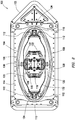
- FIGS. 1 and 2 illustrate a marine acoustic vibrator 100 in accordance with example embodiments.
- FIG. 2 is a cross-sectional view of the marine acoustic vibrator 100 taken along plane 2 of FIG. 1 .
- the marine acoustic vibrator 100 may be mounted within a frame 102.
- the frame 102 may be used for deploying the marine acoustic vibrator 100 in the water.
- the marine acoustic vibrator 100 may further comprise a vibrating element, such as flextensional shell 104.
- the flextensional shell 104 may comprise two side portions that may be mirror images of one another, best seen on FIG. 2 , as first shell side portion 106 and second shell side portion 108.
- the flextensional shell 104 may further comprise endbeams 110.
- the first shell side portion 106 and second shell side portion 108 may be flexibly coupled to the endbeams 110 (e.g., using hinges 112 or some other flexible element as shown on FIG. 2 ).
- the flextensional shell 104 may complete an enclosure surrounding other components of the marine acoustic vibrator 100.
- the marine acoustic vibrator 100 may further comprise top and bottom endplates 114.
- the flextensional shell 104 may be attached to the top and bottom endplates 114.
- the connection between the flextensional shell 104 and top and bottom endplates 114 may be a flexible connection.
- the flextensional shell 104 is depicted on FIGS. 1 and 2 as being essentially elliptic in shape, flextensional shells of other shapes, including convex, concave, flat, or combinations thereof, may also be used in accordance with embodiments of the present invention.
- the flextensional shell 104 may comprise first and second shell side portions 106, 108.
- the first and second shell side portions 106, 108 may comprise spring steel, beryllium copper alloy, glass fiber reinforced plastic, carbon fiber reinforced or other suitable flexible spring material.
- Suitable flexible spring materials may have a high yield strength and not permanently deform when acted on by the moving-coil transducer 116.
- Flextensional transducers have been divided into seven classes according to the shape of the shell and the configuration of the drive elements.
- the first and second shell side portions 106, 108 may be a class V flextensional transducer.
- FIGS. 1 and 2 illustrate the vibrating element as a flextensional shell 104, it should be understood that embodiments may use other suitable vibrating elements, such as plates, with marine acoustic vibrator 100.
- FIG. 2 illustrates the marine acoustic vibrator 100 in cross-section in accordance with example embodiments.
- the marine acoustic vibrator 100 may include a moving-coil transducer 116.
- the moving-coil transducer 116 may be operable to effect vibration of the vibrating element, such as flextensional shell 104.
- the moving-coil transducer 116 of the marine acoustic vibrator 100 may be actuated to cause vibration of flextensional shell 104, thus converting motion of moving-coil transducer to sound energy.
- FIGS. 3 and 4 the moving-coil transducer will be described in accordance with example embodiments.
- Moving-coil transducer 116 may provide the ability to generate very large acoustic amplitudes. Seismic sources using one or more moving-coil transducers 116 may be referred to as "moving-coil" projectors.
- FIGS. 2-4 illustrate a single, bi-directional moving-coil transducer, embodiments with one or more uni-directional moving-coil transducers or in which a plurality of moving-coil transducers are used in parallel are within the scope of the invention.
- the moving-coil transducer 116 may be centrally mounted in the flextensional shell 104.
- the moving-coil transducer 116 may be mounted on a fixture capable of suspending the moving-coil transducer 116 within the flextensional shell 104.
- the fixture may be coupled to the flextensional shell 104.
- the fixture may be coupled to the endbeams 110 using any suitable technique, including linear bearings.
- the moving-coil transducer 116 may comprise a magnetic assembly 118 and coil assemblies 120.
- the magnetic assembly 118 may comprise permanent magnetic material. While FIG. 2 illustrates the use of a pair of coil assemblies 120 that share magnetic material, it should be understood that the coil assemblies 120 may each have separate magnetic material, in some embodiments. As illustrated, embodiments may comprise a pair of coil assemblies 120 positioned on opposite sides of the moving-coil transducer 116.
- the coil assemblies 120 may each comprise a coil element 122. As best seen on FIG. 3 , the coil elements 122 may each comprise a pair of coils 128 that may be mechanically coupled. The coil elements 122 may be positioned in corresponding air gaps 131 in the magnetic assembly 118.
- the coil elements 122 may each be coupled to corresponding transmission elements 130.
- a magnetic field may be created.
- the magnetic field may interact with the field from the magnetic assembly 118, which may comprise permanent magnetic material, and provide relative movement of the parts.
- the transmission elements 130 may be used to transfer force from the moving-coil transducer 116 to the spring elements 132 and/or the flextensional shell 104.
- the spring elements 132 may be disposed within the flextensional shell 104.
- the spring elements 132 may generally function to transform movement of the coil elements 122 into movement of the flextensional shell 104.
- the spring elements 132 may also function to form a resonant system that improves the efficiency of generating acoustic energy in a marine environment.
- FIG. 2 example embodiments are shown in which the spring elements 132 may have a slightly arched shape.
- the spring elements 132 may be shaped as flexible plates, rods, beams, or bars, for example, and may preferably be fastened to the fastening devices 134 and may be allowed to rotate.
- the flextensional shell 104 may widen, creating a pressure wave in the environment. This way the movements of the moving-coil transducer 116 should propagate outwards and result in acoustic waves in the water.
- embodiments may be adapted to different situations. It should be understood that the present invention should not be limited to the particular configuration shown on FIGS. 1-4 , and other configurations of the marine acoustic vibrator 100 may be used in accordance with embodiments of the present invention.
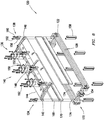
- the coil assembly 120 may comprise a compression assembly 124.
- the compression assembly 124 may assist in compressing the coil element 122, for example, to minimize thermal strain effects.
- the coil element 122 may be compressed to maintain a particular backlash and/or ensure that air gap 131 (e.g., FIG. 3 ) of a sufficient spacing is maintained.
- the compression assembly 124 may comprise a base plate 136, coil clamps 138, springs 162, and cooling system 172.
- the coil clamps 138 may be arranged along lateral edges of the base plate 136.
- arranged along the lateral edges of the base plate 136 refers to the coil clamps 138 being arranged along the outer periphery of the lateral sides of the base plate 136, wherein the lateral sides extend between either longitudinal end of the base plate 136.
- one or more of the coil clamps 138 may be applied at full compression.
- the springs 162 may be arranged to reduce a clamping force and/or reduce force due to thermal strain of the coil element 122.
- Coil clamps 138 secure the base plate 136 to the coil element 122.
- Linear bearing assemblies 140 may secure the base plate 136 to transmission element 130 (e.g., shown FIG. 2 ), which may in turn be coupled to a vibrating element (e.g., flextensional shell 104 on FIG. 2 ).
- the base plate 136 is used to facilitate transfer motion of the coil element 122 to the vibrating element (e.g., flextensional shell 104 shown FIG. 2 ) by way of the transmission element 130 (e.g., shown on FIG. 2 ).
- the base plate 136 may comprise lips 142 at one or both of lateral edges 144 of the base plate 136.
- the base plate 136 is shown as having a slight concavity; however, embodiments may include the base plate 136 being generally flat or convex in shape.
- the base plate 136 may comprise clamp holes 146 spaced around lateral edges 144 of the base plate 136 for insertion of coil clamps 138.
- the clamp holes 146 may be equally spaced, but other spacing of the clamp holes 146 may also be used in accordance with example embodiments.
- the base plate 136 may also comprise bearing holes 148 for receiving the linear bearing assemblies 140. Any suitable fastener, such as screws 150 and washers 152, may be used to secure the linear bearing assemblies 140 to base plate 136.
- the linear bearing assemblies 140 may serve to maintain a safe clearance between static (e.g., magnetic return path components) and dynamic (e.g., coil element 122 and associated components). Maintaining clearance is required to ensure the coil element 122 is not obstructed and free to create the motion required to generate acoustic signals.
- Other components that may be used to maintain this separation may include, without limitation, air bearings, thin film oil bearings, roller or ball bearings, flexures, wheels, and guides.
- coil element 122 may be positioned in an air gap 131 of a magnetic assembly 118 (e.g., shown on FIG. 3 ).
- the coil element 122 may comprise a pair of coils 128.
- the coils 128 may be mechanically coupled.
- any suitable type of coils 128 may be used including ribbon foil coils (as shown in the embodiment), bitter coils, traditional magnet wire coils, or constructed by any device carrying an electrical current that generates a magnetic field utilizing the locomotive forcing function to generate motion. While FIGS.
- embodiments of the coil element 122 may utilize a single coil 128 or three or more coils 128 in place of the pair of coils 128 that are illustrated.
- current may be sent through the coil element 122 to generate a magnetic field. Due to interaction with magnetic assembly 118 (e.g. shown on FIG. 3 ), the coil element 122 may move in air gap 131.
- An electrical connection 154 may be made at either end of the coil element 122.
- the electrical connection 154 may include one or more flexible current carrying wires with electrical terminations at either end.
- the electrical termination could consist of standard connectors capable of carrying the amount of current required to obtain the desired current density.
- the connectors must also mechanically secure the flexible wire to the coil and to the electrical circuit that generates the required electrical signal.
- the termination could also consist of a copper material (or any material with high electrical conductivity such as aluminum or silver) capable of carrying the current and providing a mechanical connection.
- coil clamps 138 are used to couple the coil element 122 to the base plate 136.
- the coil clamps 138 secure the base plate 136 to the coil element 122, for example, to maintain mechanical connection between the coil element 122 and the vibrating element (e.g., flextensional shell 104 shown on FIG 2 ).
- a plurality of coil clamps 138 is provided.
- a plurality of coil clamps 138 may be arranged along the lateral edges 144 of the base plate 136.
- the coil clamps 138 may be equally spaced along both lateral edges 144, but other spacing of the coil clamps 138 may also be selected dependent upon a particular application.
- the coil clamps 138 each comprise a first clamp portion 156 and a second clamp portion 158.
- Bolts 160 or other suitable fasteners may be used to secure the first clamp portion 156 to the second clamp portion 158.
- the bolts 160 may thread directly into the second clamp portion 158, but nuts or other suitable arrangements may also be used for closing the coil clamps 138.
- the coil clamps 138 may be configured to hold the base plate 136 and the coil element 122 tightly together to restrict movement and prevent separation through application of a pre-compression force to the coil element 122.
- the coil clamp 138 may constrain movement of the coil element 122 in at least one direction.
- movement of the coil element 122 may be constrained in the x-direction and the y-direction.
- maintaining contact between the vibrating element (e.g., flextensional shell 104 shown FIG. 2 ) and the coil element 122 by means of a pre-stressed connection may result in thermal stress buildup within the coil element 122.
- increasing acoustic output may increase the thermal stress to a point where the coil element 122 may buckle where it is unconstrained.
- the coil element 122 may be unconstrained, so the coil element 122 may twist and/or translate in the z-direction and into the air gap 131 (e.g., shown on FIG. 3 ).
- maintaining the air gap 131 may be needed as the moving-coil transducer 116 (e.g., shown on FIG. 3 ) may have a static component (e.g., magnetic assembly 118 on FIG. 3 ) and a dynamic component (e.g., coil element 122) with potentially very high velocities.
- the softer material e.g., coil element 122
- the coil element 122 may be at an electric voltage potential much higher than the magnetic assembly 118 and may need to maintain electrical separation, for example, to prevent failure due to electrical circuit damage and/or shorting. Allowing room (e.g., backlash) for thermal strain may reduce and/or minimize thermal stress buildup within the coil element 122. However, adding backlash to the design of the coil element 122 may alter the overall system dynamics causing the system to suffer from non-repeatability, among other consequences.
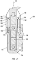
- springs 162 may be placed in a load path 164 of one or more of the coil clamps 138, for example, to reduce the resting force of the coil assembly 120 to thermal expansion. As illustrated, the springs 162 may be disposed between a head 166 of the bolts 160 and the first clamp portion 156. However, other suitable configurations may be used so that the springs 162 may allow for thermal expansion. For example, the springs 162 may be placed in the second clamp portion 158, they may also be placed between the first clamp portion 156 and second clamp portion 158. The springs may be placed anywhere in the assembly as long as they are in the same load path as the coil elements 122.
- the springs 162 may each have a spring rate sized to ensure that unloading does not occur during maximum dynamic conditions.
- the spring rate may be sufficiently compliant to allow thermal expansion of the coil element 122 without undesired twisting/buckling of the coil element into the air gap 131 (e.g., shown on FIG. 3 ).
- the springs 162 may have a spring rate of from about 289e6 Newtons per meter ("N/m") to about 392e6 N/m and alternatively, from about 322 e6 N/m to about 325 e6 N/m.
- the spring rate may be sized to ensure pre-compression is maintained in the connection during dynamic operation in that the coil assembly 120 may always be in compression with no tensile loading.
- any suitable type of spring element may be used for the springs 162 including, without limitation, disc springs, coil springs, torsional springs, leaf springs, or any device with a spring rate near the target values.
- the springs 162 may be in the form of a stack of disc springs in parallel.
- Disc springs are generally a type of spring shaped like a washer and may also be known as Belleville washers or Belleville springs.
- Embodiments of the compression assembly 124 may further comprise a spacer 168 and an insulating element 170, as illustrated on FIGS. 5 and 6 .
- Spacer 168 may be disposed between base plate 136 and coil element 122.
- spacer 168 may be in the form of a pair of plates positioned on either lateral side of the base plate 136 and generally placed transverse to the base plate 136.
- the spacer 168 may comprise a material with low density to minimize dynamic mass and have good mechanical properties, such as high Young's modulus and compressive strength. Examples of suitable materials may include fiberglass, fiberglass epoxy laminates (e.g., Garolite) glass-filled polyetherimide and other glass-filled materials.
- insulating element 170 may be arranged to electrically insulate the lateral sides of coil element 122.
- the lateral sides of coil element 122 may be sandwiched between corresponding layers of the insulating element 170.
- insulating element 170 may comprise any suitable material, including most thermoplastic materials, epoxies, or resins with high electrical resistivity.
- Embodiments of the compression assembly 124 may further comprise a cooling system 172, as illustrated on FIGS. 5-8 .
- Cooling system 172 may be operable to circulate a coolant to remove heat from coil element 122.
- Cooling system 172 may comprise cooling channels 174 for circulation of the coolant.
- the cooling channels 174 may be pathways arranged along the coil element 122 that direct the flow of a coolant through cooling system 172 and along the coil element 122.
- the cooling channels 174 may comprise sealed pipes, tubes, or other conduit through which flow of the coolant may be directed. While the coolant may not be in direct contact with the coil element 122, heat may be transferred from coil element 122 to coolant by conduction.
- cooling channels 174 may extend at least partially along the coil element 122.
- cooling channels 174 may be on top of and below the lateral sides of the coil element 122.
- the cooling channels 174 may be clamped to the coil element 122 by way of coil clamps 138.
- the springs 162 may be sized to reduce, prevent, and/or minimize unloading of the coil element 122 to the interface with the cooling channels 174.
- the springs 162 may be sized to prevent coil element 122 to cooling channel 174 un-coupling under a hypothetical full dynamic load.
- a clamping force applied to the coil element 122 may be reduced, for example, to allow for sliding between the cooling channels 174 and the coil element 122.
- one set of the coil clamps 138 may be clamped more than another set of the coil clamps 138. That is, one set of the coil clamps 138 may operate at a higher magnitude of torque than another set of the coil clamps 138.
- the coil clamps 138 on one lateral side of the base plate 136 may be clamped more than the coil clamps on the other lateral side of the base plate 136.
- At least one of the remaining coil clamps 138 may have a reduced torque applied and/or may include a washer (e.g., a Belleville spring) for example, under a head 166 of one of the bolts 160.
- a washer e.g., a Belleville spring
- reducing the amount of torque applied to one set of coil clamps 138 may reduce an amount of backlash in the system.
- grease may be applied to one or more of the coil clamps 138, one or more of the coil elements 122, and/or the washer to facilitate a reduction in frictional force between the components.
- thermal grease could be applied to one or more of the components.
- one or more of the coil clamps 138 may be secured while the coil element 122 is under thermal load.
- the temperature of the coil element 122 may be elevated allowing it to expand to full thermal strain and then applying torque to the coil clamps 138.
- a tensile load may be applied as the temperature of the coil element 122 is altered. This may reduce or eliminate compressive stress and lead to a reduction in buckling.
- a stiffness of the coil assembly 120 may be increased.
- the coils 126 may be bonded at a particular edge.
- the coils 126 may be bonded at a bottom edge.
- an epoxy bond may be added between one or more of the coils 126.
- additional stiffness may be provided to the coils 126 to reduce bending and/or buckling.
- the coil element 122 may be bonded and/or coupled to one or more cooling channels 174.
- At least one of the cooling channels 174 may be segmented.
- at least one of the cooling channels 174 may be segmented with joints to allow for the at least one of the cooling channels 174 to move (e.g., "float") with expansion of the coil element 122.
- the cooling channels 174 may comprise multiple channel portions that may each by separated by spaced joints.
- the cooling channels 174 may comprise a first cooling channel portion and a second cooling channel portion, wherein a joint may join the first cooling channel portion and the second cooling channel portion.
- the joint may be constructed to allow movement so that first cooling channel portion and the second cooling channel portion may be allowed to move with respect to one another, thus enabling the cooling channels 174 to move with expansion of the coil element 122.
- axial stiffness of the cooling channels 174 may be reduced.
- an interface for example, a low friction interface, may be added between the coil element 122 and at least one of the cooling channels 174.
- a low friction coefficient ceramic insulator may be added between the coil element 122 and at least one of the cooling channels 174 to allow for the coil element 122 to expand and/or contract.
- a thermal path may be provided, for example, via a copper ribbon, to one or more sides of the at least one of the cooling channels 174.
- a thermal path may be "sandwiched" between one of the coils 127 and a low friction material.
- the coil element 122 may be bound inside of a Garolite "H" structure to reduce localized twisting, for example.
- the "H" structure may provide the necessary mechanical structure to withstand the forces generated by the thermal stress of the coil element 122, the locations inside the structure where material is not present (between the upper and lower channels) are where the coil element 122 resides.
- the coil element 122 may comprise an hourglass planform coil.
- An hourglass planform coil may allow for buckle prevention.
- a thermally conductive and/or electrically insulative material may be interleaved with the coil element 122 and/or a conductor of the coil element 122 (i.e., coil conductor).
- direct heat transfer may be facilitated from the coil element 122 and/or coil conductor to an interleaved material to at least one of the cooling channels 174. For example, heat may be directly transferred from the coil element 122 and/or coil conductor to a thin conductive material to a cooling channel.
- the coil element 122 may comprise a bitter coil design.
- a cooling system may be provided to flush and/or bypass various manifolds in the coil assembly 120, for example, aluminum manifolds, or comprising a material with high thermal conductivity.
- coolant may be in direct contact with coil conductors, which may reduce or eliminate a thermal insulation boundary.
- the manifold may be comprised of one or more combinations of materials.
- the bitter coil design may minimize thermal expansion of coil conductors (e.g., copper conductors) in the coil element 122 and/or may provide a reduction of thermal heating within the coil element 122.
- the air gap 131 may be enlarged to provide additional space and/or clearance.
- the air gap 131 associated with the magnetic assembly 118 may be enlarged to provide additional space and/or clearance, for example between the magnetic assembly 118 and the coil element 122.
- FIG. 9 illustrates an example technique for acquiring marine seismic data that may be used with embodiments of the present techniques.
- a survey vessel 176 moves along the surface of a body of water 178, such as a lake or ocean.
- the survey vessel 176 may include thereon equipment, shown generally at 180 and collectively referred to herein as a "recording system.”
- the recording system 180 may include devices (none shown separately) for detecting and making a time indexed record of signals generated by each of seismic sensors 182 (explained further below) and for actuating a marine acoustic vibrator 100 at selected times.
- the recording system 180 may also include devices (none shown separately) for determining the geodetic position of the survey vessel 176 and the various seismic sensors 182.
- the survey vessel 176 may tow the marine acoustic vibrator 100 in the body of water 178.
- a method may include disposing the marine acoustic vibrator 100 in the body of water 178.
- a source cable 184 may couple the marine acoustic vibrator 100 to the survey vessel 52. While only a single marine acoustic vibrator 100 is shown in FIG. 9 , it is contemplated that embodiments may include more than one marine acoustic vibrator 100 towed by the survey vessel 176 or a different vessel. In some embodiments, one or more arrays of marine acoustic vibrators 100 may be used.
- the marine acoustic vibrator 100 may be triggered, for example, by the recording system 180, to generate acoustic energy.
- the survey vessel 176 (or a different vessel) may further tow at least one sensor streamer 186 to detect the acoustic energy after it has interacted, for example, with one or more subterranean formations 188 below the water bottom 190.
- both the marine acoustic vibrator 100 and the sensor streamer 186 may be towed above the water bottom 190.
- more than one sensor streamer 186 may be towed by the survey vessel 176, which may be spaced apart laterally, vertically, or both laterally and vertically.
- the sensor streamer 186 may contain seismic sensors 182 thereon at spaced apart locations.
- the seismic sensors 182 may be any type of seismic sensors 182 known in the art, including hydrophones, particle velocity sensors, particle displacement sensors, particle acceleration sensors, or pressure gradient sensors, for example.
- the seismic sensors 182 may generate response signals, such as electrical or optical signals, in response to detected acoustic energy. Signals generated by the seismic sensors 182 may be communicated to the recording system 180.
- the detected energy may be used to infer certain properties of the one or more subterranean formations 188, such as structure, mineral composition and fluid content, thereby providing information useful in the recovery of hydrocarbons.
- a geophysical data product indicative of certain properties of the one or more subterranean formations 188 may be produced from the detected acoustic energy.
- the geophysical data product may include acquired and/or processed seismic data and may be stored on a non-transitory, tangible computer-readable medium.
- the geophysical data product may be produced offshore (i.e. by equipment on a vessel) or onshore (i.e. at a facility on land) either within the United States and/or in another country.
- embodiments may include producing a geophysical data product from at least the measured acoustic energy and storing the geophysical data product on a tangible, non-volatile computer-readable medium suitable for importing onshore.
- the geophysical data product is produced offshore and/or in another country, it may be imported onshore to a facility in, for example, the United States or another country. Once onshore in, for example, the United States (or another country), further processing and/or geophysical analysis may be performed on the geophysical data product.
Landscapes
- Engineering & Computer Science (AREA)
- Physics & Mathematics (AREA)
- Life Sciences & Earth Sciences (AREA)
- Remote Sensing (AREA)
- Acoustics & Sound (AREA)
- Geology (AREA)
- Environmental & Geological Engineering (AREA)
- General Life Sciences & Earth Sciences (AREA)
- General Physics & Mathematics (AREA)
- Geophysics (AREA)
- Multimedia (AREA)
- Mechanical Engineering (AREA)
- Oceanography (AREA)
- Apparatuses For Generation Of Mechanical Vibrations (AREA)
- Cooling Or The Like Of Electrical Apparatus (AREA)
Claims (9)
- Akustischer Meeresvibrator (100), der Folgendes umfasst:ein vibrierendes Element (104); undeinen Drehspulgeber (116), der mit dem vibrierenden Element (104) gekoppelt ist und betriebsfähig ist, um ein Vibrieren des vibrierenden Elementes (104) zu bewirken, wobei der Drehspulgeber (116) Folgendes umfasst:ein Spulenelement (122), umfassend eine Spule (128);mehrere Spulenklemmen (138), die die Bewegung des Spulenelements (122) in wenigstens einer Richtung einschränken;eine Grundplatte (136) zum Erleichtern der Bewegungsübertragung des Spulenelements (122) auf das vibrierende Element (104), wobei die mehreren Spulenklemmen (138) die Grundplatte (136) an dem Spulenelement (122) sichern; undgekennzeichnet durch eine Feder (162), die in einem Lastpfad jeder Spulenklemme (138) angeordnet ist, wobei jede Spulenklemme (138) einen ersten Klemmenabschnitt (156), einen zweiten Klemmenabschnitt (158) und einen Bolzen (160) umfasst, der den ersten Klemmenabschnitt (156) an dem zweiten Klemmenabschnitt (158) sichert, wobei die Feder (162) zwischen einem Kopf (166) des Bolzens (160) und dem ersten Klemmenabschnitt (156) angeordnet ist.
- Akustischer Meeresvibrator (100) nach Anspruch 1, wobei das vibrierende Element (104) eine flextensionale Hülle ist.
- Akustischer Meeresvibrator (100) nach Anspruch 1 oder 2, wobei die Feder (162) aus der Gruppe bestehend aus einer Tellerfeder, einer Schraubenfeder, einer Torsionsfeder, einer Blattfeder und einer beliebigen Kombination davon ausgewählt ist.
- Akustischer Meeresvibrator (100) nach einem der Ansprüche 1 bis 3, wobei die Feder (162) eine Federrate von etwa 289e6 Newton pro Meter bis etwa 329e6 Newton pro Meter aufweist.
- Akustischer Meeresvibrator (100) nach einem der Ansprüche 1 bis 4, wobei die mehreren Spulenklemmen (138) entlang der Seitenkanten der Grundplatte (136) angeordnet sind.
- Akustischer Meeresvibrator (100) nach einem der Ansprüche 1 bis 5, ferner umfassend ein Kühlsystem (172), wobei das Kühlsystem (172) Kühlkanäle (174) umfasst, die entlang des Spulenelements (122) angeordnet sind, wobei vorzugsweise wenigstens einer der Kühlkanäle (174) mit Gelenken segmentiert ist, um eine Bewegung wenigstens eines der Kühlkanäle (174) mit Ausdehnung des Spulenelements (122) zu ermöglichen.
- Akustischer Meeresvibrator (100) nach einem der Ansprüche 1 bis 6, wobei die Spule (128) eine Bitter-Spule ist.
- Verfahren, das Folgendes umfasst:
Anordnen des akustischen Meeresvibrators (100) nach einem der vorhergehenden Ansprüche in einem Gewässer; und
Betätigen des Drehspulgebers (116) des akustischen Meeresvibrators (100), um zu bewirken, dass das vibrierende (104) des akustischen Meeresvibrators (100) akustische Energie erzeugt, wobei die Feder (162) in dem Lastpfad jeder Spulenklemme (138) angeordnet ist, um eine Wärmeausdehnung des Spulenelements des Drehspulgebers (116) zu ermöglichen. - Verfahren nach Anspruch 8, das ferner Folgendes umfasst:Erfassen der akustischen Energie, nachdem die akustische Energie mit einer oder mehreren unterirdischen Formationen unterhalb eines Wasserspiegels interagiert hat; undProduzieren eines geophysikalischen Datenprodukts, das eine oder mehrere Eigenschaften der einen oder mehreren unterirdischen Formationen anzeigt.
Applications Claiming Priority (2)
| Application Number | Priority Date | Filing Date | Title |
|---|---|---|---|
| US201562211957P | 2015-08-31 | 2015-08-31 | |
| US15/193,765 US10605934B2 (en) | 2015-08-31 | 2016-06-27 | Apparatus with thermal stress relief mechanism for heat generating coil and associated methods |
Publications (3)
| Publication Number | Publication Date |
|---|---|
| EP3136129A2 EP3136129A2 (de) | 2017-03-01 |
| EP3136129A3 EP3136129A3 (de) | 2017-05-17 |
| EP3136129B1 true EP3136129B1 (de) | 2021-03-24 |
Family
ID=56801473
Family Applications (1)
| Application Number | Title | Priority Date | Filing Date |
|---|---|---|---|
| EP16185851.9A Active EP3136129B1 (de) | 2015-08-31 | 2016-08-26 | Maritimer akustischer vibrator mit mechanismus zur reduzierung von thermischer spannung für wärmeerzeugende spule und zugehöriges verfahren |
Country Status (3)
| Country | Link |
|---|---|
| US (1) | US10605934B2 (de) |
| EP (1) | EP3136129B1 (de) |
| BR (1) | BR102016019379B1 (de) |
Families Citing this family (4)
| Publication number | Priority date | Publication date | Assignee | Title |
|---|---|---|---|---|
| US11041973B2 (en) * | 2015-11-17 | 2021-06-22 | Fairfield Industries Incorporated | Back deck automation |
| US11035970B2 (en) * | 2019-06-19 | 2021-06-15 | Magseis Ff Llc | Interleaved marine diffraction survey |
| CN112822908B (zh) * | 2020-08-31 | 2021-10-22 | 中国科学院声学研究所 | 一种用于弯张换能器多途径散热结构 |
| IT202200021414A1 (it) * | 2022-10-18 | 2024-04-18 | Advanced Scient Sensors And Systems S R L | Sensore direttivo per la misura di infrasuoni, e relativo emettitore di infrasuoni |
Family Cites Families (19)
| Publication number | Priority date | Publication date | Assignee | Title |
|---|---|---|---|---|
| US1164452A (en) | 1915-09-22 | 1915-12-14 | August R Beiersdorf | Valve-spring compressor. |
| US1351424A (en) | 1919-07-17 | 1920-08-31 | Frank E Jenkins | Valve-spring compressor |
| GB640462A (en) | 1946-06-25 | 1950-07-19 | British Thomson Houston Co Ltd | Improvements in and relating to electromagnetic induction apparatus |
| GB1120151A (en) | 1965-09-13 | 1968-07-17 | Mccollum Lab Inc | Seismic radiator |
| US4009461A (en) | 1975-07-24 | 1977-02-22 | General Electric Company | Externally actuated clamping system for transformer windings incorporating a mechanical follow-up device |
| WO1998057311A2 (en) | 1997-06-13 | 1998-12-17 | Itron, Inc. | Telemetry antenna system |
| AU5161300A (en) | 1999-05-24 | 2000-12-12 | Edge Technologies, Inc. | High power ultrasonic transducer having a plurality of sub-motors connected to asingle horn |
| US8289867B2 (en) * | 2008-08-01 | 2012-10-16 | Qualcomm Atheros, Inc. | Message routing mechanism for communication networks |
| US8446798B2 (en) * | 2010-06-29 | 2013-05-21 | Pgs Geophysical As | Marine acoustic vibrator having enhanced low-frequency amplitude |
| US9188691B2 (en) * | 2011-07-05 | 2015-11-17 | Pgs Geophysical As | Towing methods and systems for geophysical surveys |
| US8670292B2 (en) | 2011-08-12 | 2014-03-11 | Pgs Geophysical As | Electromagnetic linear actuators for marine acoustic vibratory sources |
| US10473803B2 (en) | 2013-02-08 | 2019-11-12 | Pgs Geophysical As | Marine seismic vibrators and methods of use |
| US9645264B2 (en) | 2013-05-07 | 2017-05-09 | Pgs Geophysical As | Pressure-compensated sources |
| US9995834B2 (en) | 2013-05-07 | 2018-06-12 | Pgs Geophysical As | Variable mass load marine vibrator |
| US9864080B2 (en) | 2013-05-15 | 2018-01-09 | Pgs Geophysical As | Gas spring compensation marine acoustic vibrator |
| US9618637B2 (en) | 2013-09-20 | 2017-04-11 | Pgs Geophysical As | Low frequency marine acoustic vibrator |
| US9507037B2 (en) | 2013-09-20 | 2016-11-29 | Pgs Geophysical As | Air-spring compensation in a piston-type marine vibrator |
| US9360574B2 (en) | 2013-09-20 | 2016-06-07 | Pgs Geophysical As | Piston-type marine vibrators comprising a compliance chamber |
| US9341725B2 (en) * | 2013-09-20 | 2016-05-17 | Pgs Geophysical As | Piston integrated variable mass load |
-
2016
- 2016-06-27 US US15/193,765 patent/US10605934B2/en active Active
- 2016-08-23 BR BR102016019379-6A patent/BR102016019379B1/pt active IP Right Grant
- 2016-08-26 EP EP16185851.9A patent/EP3136129B1/de active Active
Non-Patent Citations (1)
| Title |
|---|
| None * |
Also Published As
| Publication number | Publication date |
|---|---|
| BR102016019379B1 (pt) | 2023-01-31 |
| EP3136129A2 (de) | 2017-03-01 |
| US10605934B2 (en) | 2020-03-31 |
| BR102016019379A2 (pt) | 2017-03-07 |
| US20170059725A1 (en) | 2017-03-02 |
| EP3136129A3 (de) | 2017-05-17 |
Similar Documents
| Publication | Publication Date | Title |
|---|---|---|
| EP3136129B1 (de) | Maritimer akustischer vibrator mit mechanismus zur reduzierung von thermischer spannung für wärmeerzeugende spule und zugehöriges verfahren | |
| US9618637B2 (en) | Low frequency marine acoustic vibrator | |
| US9360574B2 (en) | Piston-type marine vibrators comprising a compliance chamber | |
| Prasad et al. | Analytical electroacoustic model of a piezoelectric composite circular plate | |
| US8670292B2 (en) | Electromagnetic linear actuators for marine acoustic vibratory sources | |
| US5789844A (en) | Acoustic transducer | |
| BRPI1102801A2 (pt) | vibrador acéstico marÍtimo possuindo baixa amplitude de frequÊncia aperfeiÇoada | |
| CN108431637A (zh) | 多轴单质量体加速度计 | |
| US10734877B2 (en) | Electromagnetic energy transducer | |
| US20130193693A1 (en) | Multimodal vibration harvester combining inductive and magnetostrictive mechanisms | |
| AU2014216042B2 (en) | Piezoelectric accelerometer | |
| CN206497210U (zh) | 地震勘测设备 | |
| US10539694B2 (en) | Piezoelectric bender with additional constructive resonance | |
| US8610318B2 (en) | Moving magnet actuator magnet carrier | |
| EA029634B1 (ru) | Источник со скомпенсированным давлением | |
| WO1987005707A1 (en) | Downhole electromagnetic seismic source | |
| US20170329097A1 (en) | Clamp and Bending Strain Relief Apparatus and Methods | |
| CN104112624B (zh) | 由深度激活的传感器开关和方法 | |
| EP3236292A1 (de) | Seismischer niederfrequenz-meeresvibrator und verfahren zur verwendung | |
| US10964668B2 (en) | Stacked transistor packages | |
| US20200393584A1 (en) | Mono and Dipole Acoustic Projector | |
| Collinger et al. | An investigation into using magnetically attached piezoelectric elements for vibration control | |
| Sherman et al. | Transducers as hydrophones |
Legal Events
| Date | Code | Title | Description |
|---|---|---|---|
| PUAI | Public reference made under article 153(3) epc to a published international application that has entered the european phase |
Free format text: ORIGINAL CODE: 0009012 |
|
| STAA | Information on the status of an ep patent application or granted ep patent |
Free format text: STATUS: THE APPLICATION HAS BEEN PUBLISHED |
|
| AK | Designated contracting states |
Kind code of ref document: A2 Designated state(s): AL AT BE BG CH CY CZ DE DK EE ES FI FR GB GR HR HU IE IS IT LI LT LU LV MC MK MT NL NO PL PT RO RS SE SI SK SM TR |
|
| AX | Request for extension of the european patent |
Extension state: BA ME |
|
| PUAL | Search report despatched |
Free format text: ORIGINAL CODE: 0009013 |
|
| AK | Designated contracting states |
Kind code of ref document: A3 Designated state(s): AL AT BE BG CH CY CZ DE DK EE ES FI FR GB GR HR HU IE IS IT LI LT LU LV MC MK MT NL NO PL PT RO RS SE SI SK SM TR |
|
| AX | Request for extension of the european patent |
Extension state: BA ME |
|
| RIC1 | Information provided on ipc code assigned before grant |
Ipc: G01V 1/145 20060101AFI20170410BHEP Ipc: G10K 9/12 20060101ALI20170410BHEP |
|
| STAA | Information on the status of an ep patent application or granted ep patent |
Free format text: STATUS: REQUEST FOR EXAMINATION WAS MADE |
|
| 17P | Request for examination filed |
Effective date: 20171109 |
|
| RBV | Designated contracting states (corrected) |
Designated state(s): AL AT BE BG CH CY CZ DE DK EE ES FI FR GB GR HR HU IE IS IT LI LT LU LV MC MK MT NL NO PL PT RO RS SE SI SK SM TR |
|
| STAA | Information on the status of an ep patent application or granted ep patent |
Free format text: STATUS: EXAMINATION IS IN PROGRESS |
|
| 17Q | First examination report despatched |
Effective date: 20200616 |
|
| GRAP | Despatch of communication of intention to grant a patent |
Free format text: ORIGINAL CODE: EPIDOSNIGR1 |
|
| STAA | Information on the status of an ep patent application or granted ep patent |
Free format text: STATUS: GRANT OF PATENT IS INTENDED |
|
| INTG | Intention to grant announced |
Effective date: 20201007 |
|
| RIN1 | Information on inventor provided before grant (corrected) |
Inventor name: MCGREGOR, AARON Inventor name: REINDERS, TODD ALLAN Inventor name: KAUFMAN, RICK |
|
| GRAS | Grant fee paid |
Free format text: ORIGINAL CODE: EPIDOSNIGR3 |
|
| GRAA | (expected) grant |
Free format text: ORIGINAL CODE: 0009210 |
|
| STAA | Information on the status of an ep patent application or granted ep patent |
Free format text: STATUS: THE PATENT HAS BEEN GRANTED |
|
| AK | Designated contracting states |
Kind code of ref document: B1 Designated state(s): AL AT BE BG CH CY CZ DE DK EE ES FI FR GB GR HR HU IE IS IT LI LT LU LV MC MK MT NL NO PL PT RO RS SE SI SK SM TR |
|
| REG | Reference to a national code |
Ref country code: GB Ref legal event code: FG4D |
|
| REG | Reference to a national code |
Ref country code: CH Ref legal event code: EP |
|
| REG | Reference to a national code |
Ref country code: IE Ref legal event code: FG4D |
|
| REG | Reference to a national code |
Ref country code: AT Ref legal event code: REF Ref document number: 1375060 Country of ref document: AT Kind code of ref document: T Effective date: 20210415 Ref country code: DE Ref legal event code: R096 Ref document number: 602016054722 Country of ref document: DE |
|
| REG | Reference to a national code |
Ref country code: LT Ref legal event code: MG9D |
|
| PG25 | Lapsed in a contracting state [announced via postgrant information from national office to epo] |
Ref country code: NO Free format text: LAPSE BECAUSE OF FAILURE TO SUBMIT A TRANSLATION OF THE DESCRIPTION OR TO PAY THE FEE WITHIN THE PRESCRIBED TIME-LIMIT Effective date: 20210624 Ref country code: BG Free format text: LAPSE BECAUSE OF FAILURE TO SUBMIT A TRANSLATION OF THE DESCRIPTION OR TO PAY THE FEE WITHIN THE PRESCRIBED TIME-LIMIT Effective date: 20210624 Ref country code: HR Free format text: LAPSE BECAUSE OF FAILURE TO SUBMIT A TRANSLATION OF THE DESCRIPTION OR TO PAY THE FEE WITHIN THE PRESCRIBED TIME-LIMIT Effective date: 20210324 Ref country code: GR Free format text: LAPSE BECAUSE OF FAILURE TO SUBMIT A TRANSLATION OF THE DESCRIPTION OR TO PAY THE FEE WITHIN THE PRESCRIBED TIME-LIMIT Effective date: 20210625 Ref country code: FI Free format text: LAPSE BECAUSE OF FAILURE TO SUBMIT A TRANSLATION OF THE DESCRIPTION OR TO PAY THE FEE WITHIN THE PRESCRIBED TIME-LIMIT Effective date: 20210324 |
|
| PG25 | Lapsed in a contracting state [announced via postgrant information from national office to epo] |
Ref country code: LV Free format text: LAPSE BECAUSE OF FAILURE TO SUBMIT A TRANSLATION OF THE DESCRIPTION OR TO PAY THE FEE WITHIN THE PRESCRIBED TIME-LIMIT Effective date: 20210324 Ref country code: RS Free format text: LAPSE BECAUSE OF FAILURE TO SUBMIT A TRANSLATION OF THE DESCRIPTION OR TO PAY THE FEE WITHIN THE PRESCRIBED TIME-LIMIT Effective date: 20210324 Ref country code: SE Free format text: LAPSE BECAUSE OF FAILURE TO SUBMIT A TRANSLATION OF THE DESCRIPTION OR TO PAY THE FEE WITHIN THE PRESCRIBED TIME-LIMIT Effective date: 20210324 |
|
| REG | Reference to a national code |
Ref country code: NL Ref legal event code: MP Effective date: 20210324 |
|
| REG | Reference to a national code |
Ref country code: AT Ref legal event code: MK05 Ref document number: 1375060 Country of ref document: AT Kind code of ref document: T Effective date: 20210324 |
|
| PG25 | Lapsed in a contracting state [announced via postgrant information from national office to epo] |
Ref country code: NL Free format text: LAPSE BECAUSE OF FAILURE TO SUBMIT A TRANSLATION OF THE DESCRIPTION OR TO PAY THE FEE WITHIN THE PRESCRIBED TIME-LIMIT Effective date: 20210324 |
|
| PG25 | Lapsed in a contracting state [announced via postgrant information from national office to epo] |
Ref country code: LT Free format text: LAPSE BECAUSE OF FAILURE TO SUBMIT A TRANSLATION OF THE DESCRIPTION OR TO PAY THE FEE WITHIN THE PRESCRIBED TIME-LIMIT Effective date: 20210324 Ref country code: EE Free format text: LAPSE BECAUSE OF FAILURE TO SUBMIT A TRANSLATION OF THE DESCRIPTION OR TO PAY THE FEE WITHIN THE PRESCRIBED TIME-LIMIT Effective date: 20210324 Ref country code: CZ Free format text: LAPSE BECAUSE OF FAILURE TO SUBMIT A TRANSLATION OF THE DESCRIPTION OR TO PAY THE FEE WITHIN THE PRESCRIBED TIME-LIMIT Effective date: 20210324 Ref country code: AT Free format text: LAPSE BECAUSE OF FAILURE TO SUBMIT A TRANSLATION OF THE DESCRIPTION OR TO PAY THE FEE WITHIN THE PRESCRIBED TIME-LIMIT Effective date: 20210324 Ref country code: SM Free format text: LAPSE BECAUSE OF FAILURE TO SUBMIT A TRANSLATION OF THE DESCRIPTION OR TO PAY THE FEE WITHIN THE PRESCRIBED TIME-LIMIT Effective date: 20210324 |
|
| PG25 | Lapsed in a contracting state [announced via postgrant information from national office to epo] |
Ref country code: IS Free format text: LAPSE BECAUSE OF FAILURE TO SUBMIT A TRANSLATION OF THE DESCRIPTION OR TO PAY THE FEE WITHIN THE PRESCRIBED TIME-LIMIT Effective date: 20210724 Ref country code: PL Free format text: LAPSE BECAUSE OF FAILURE TO SUBMIT A TRANSLATION OF THE DESCRIPTION OR TO PAY THE FEE WITHIN THE PRESCRIBED TIME-LIMIT Effective date: 20210324 Ref country code: PT Free format text: LAPSE BECAUSE OF FAILURE TO SUBMIT A TRANSLATION OF THE DESCRIPTION OR TO PAY THE FEE WITHIN THE PRESCRIBED TIME-LIMIT Effective date: 20210726 Ref country code: ES Free format text: LAPSE BECAUSE OF FAILURE TO SUBMIT A TRANSLATION OF THE DESCRIPTION OR TO PAY THE FEE WITHIN THE PRESCRIBED TIME-LIMIT Effective date: 20210324 Ref country code: SK Free format text: LAPSE BECAUSE OF FAILURE TO SUBMIT A TRANSLATION OF THE DESCRIPTION OR TO PAY THE FEE WITHIN THE PRESCRIBED TIME-LIMIT Effective date: 20210324 Ref country code: RO Free format text: LAPSE BECAUSE OF FAILURE TO SUBMIT A TRANSLATION OF THE DESCRIPTION OR TO PAY THE FEE WITHIN THE PRESCRIBED TIME-LIMIT Effective date: 20210324 |
|
| REG | Reference to a national code |
Ref country code: DE Ref legal event code: R097 Ref document number: 602016054722 Country of ref document: DE |
|
| PG25 | Lapsed in a contracting state [announced via postgrant information from national office to epo] |
Ref country code: DK Free format text: LAPSE BECAUSE OF FAILURE TO SUBMIT A TRANSLATION OF THE DESCRIPTION OR TO PAY THE FEE WITHIN THE PRESCRIBED TIME-LIMIT Effective date: 20210324 Ref country code: AL Free format text: LAPSE BECAUSE OF FAILURE TO SUBMIT A TRANSLATION OF THE DESCRIPTION OR TO PAY THE FEE WITHIN THE PRESCRIBED TIME-LIMIT Effective date: 20210324 |
|
| PLBE | No opposition filed within time limit |
Free format text: ORIGINAL CODE: 0009261 |
|
| STAA | Information on the status of an ep patent application or granted ep patent |
Free format text: STATUS: NO OPPOSITION FILED WITHIN TIME LIMIT |
|
| PG25 | Lapsed in a contracting state [announced via postgrant information from national office to epo] |
Ref country code: SI Free format text: LAPSE BECAUSE OF FAILURE TO SUBMIT A TRANSLATION OF THE DESCRIPTION OR TO PAY THE FEE WITHIN THE PRESCRIBED TIME-LIMIT Effective date: 20210324 |
|
| REG | Reference to a national code |
Ref country code: DE Ref legal event code: R119 Ref document number: 602016054722 Country of ref document: DE |
|
| 26N | No opposition filed |
Effective date: 20220104 |
|
| REG | Reference to a national code |
Ref country code: CH Ref legal event code: PL |
|
| PG25 | Lapsed in a contracting state [announced via postgrant information from national office to epo] |
Ref country code: MC Free format text: LAPSE BECAUSE OF FAILURE TO SUBMIT A TRANSLATION OF THE DESCRIPTION OR TO PAY THE FEE WITHIN THE PRESCRIBED TIME-LIMIT Effective date: 20210324 |
|
| REG | Reference to a national code |
Ref country code: BE Ref legal event code: MM Effective date: 20210831 |
|
| PG25 | Lapsed in a contracting state [announced via postgrant information from national office to epo] |
Ref country code: LI Free format text: LAPSE BECAUSE OF NON-PAYMENT OF DUE FEES Effective date: 20210831 Ref country code: CH Free format text: LAPSE BECAUSE OF NON-PAYMENT OF DUE FEES Effective date: 20210831 |
|
| PG25 | Lapsed in a contracting state [announced via postgrant information from national office to epo] |
Ref country code: IS Free format text: LAPSE BECAUSE OF FAILURE TO SUBMIT A TRANSLATION OF THE DESCRIPTION OR TO PAY THE FEE WITHIN THE PRESCRIBED TIME-LIMIT Effective date: 20210724 Ref country code: LU Free format text: LAPSE BECAUSE OF NON-PAYMENT OF DUE FEES Effective date: 20210826 |
|
| PG25 | Lapsed in a contracting state [announced via postgrant information from national office to epo] |
Ref country code: IE Free format text: LAPSE BECAUSE OF NON-PAYMENT OF DUE FEES Effective date: 20210826 Ref country code: FR Free format text: LAPSE BECAUSE OF NON-PAYMENT OF DUE FEES Effective date: 20210831 Ref country code: DE Free format text: LAPSE BECAUSE OF NON-PAYMENT OF DUE FEES Effective date: 20220301 Ref country code: BE Free format text: LAPSE BECAUSE OF NON-PAYMENT OF DUE FEES Effective date: 20210831 |
|
| PG25 | Lapsed in a contracting state [announced via postgrant information from national office to epo] |
Ref country code: IT Free format text: LAPSE BECAUSE OF FAILURE TO SUBMIT A TRANSLATION OF THE DESCRIPTION OR TO PAY THE FEE WITHIN THE PRESCRIBED TIME-LIMIT Effective date: 20210324 |
|
| PG25 | Lapsed in a contracting state [announced via postgrant information from national office to epo] |
Ref country code: HU Free format text: LAPSE BECAUSE OF FAILURE TO SUBMIT A TRANSLATION OF THE DESCRIPTION OR TO PAY THE FEE WITHIN THE PRESCRIBED TIME-LIMIT; INVALID AB INITIO Effective date: 20160826 |
|
| P01 | Opt-out of the competence of the unified patent court (upc) registered |
Effective date: 20230516 |
|
| PG25 | Lapsed in a contracting state [announced via postgrant information from national office to epo] |
Ref country code: CY Free format text: LAPSE BECAUSE OF FAILURE TO SUBMIT A TRANSLATION OF THE DESCRIPTION OR TO PAY THE FEE WITHIN THE PRESCRIBED TIME-LIMIT Effective date: 20210324 |
|
| PG25 | Lapsed in a contracting state [announced via postgrant information from national office to epo] |
Ref country code: MK Free format text: LAPSE BECAUSE OF FAILURE TO SUBMIT A TRANSLATION OF THE DESCRIPTION OR TO PAY THE FEE WITHIN THE PRESCRIBED TIME-LIMIT Effective date: 20210324 |
|
| PG25 | Lapsed in a contracting state [announced via postgrant information from national office to epo] |
Ref country code: MT Free format text: LAPSE BECAUSE OF FAILURE TO SUBMIT A TRANSLATION OF THE DESCRIPTION OR TO PAY THE FEE WITHIN THE PRESCRIBED TIME-LIMIT Effective date: 20210324 |
|
| PGFP | Annual fee paid to national office [announced via postgrant information from national office to epo] |
Ref country code: GB Payment date: 20250827 Year of fee payment: 10 |
|
| PG25 | Lapsed in a contracting state [announced via postgrant information from national office to epo] |
Ref country code: TR Free format text: LAPSE BECAUSE OF FAILURE TO SUBMIT A TRANSLATION OF THE DESCRIPTION OR TO PAY THE FEE WITHIN THE PRESCRIBED TIME-LIMIT Effective date: 20210324 |