EP3136002B1 - Door handle for a door of a domestic appliance - Google Patents
Door handle for a door of a domestic appliance Download PDFInfo
- Publication number
- EP3136002B1 EP3136002B1 EP15182703.7A EP15182703A EP3136002B1 EP 3136002 B1 EP3136002 B1 EP 3136002B1 EP 15182703 A EP15182703 A EP 15182703A EP 3136002 B1 EP3136002 B1 EP 3136002B1
- Authority
- EP
- European Patent Office
- Prior art keywords
- door
- handle
- housing
- handle bar
- oven
- Prior art date
- Legal status (The legal status is an assumption and is not a legal conclusion. Google has not performed a legal analysis and makes no representation as to the accuracy of the status listed.)
- Not-in-force
Links
- 238000010411 cooking Methods 0.000 claims description 37
- 239000011521 glass Substances 0.000 claims description 30
- 239000004033 plastic Substances 0.000 claims description 7
- 229920003023 plastic Polymers 0.000 claims description 7
- 230000001939 inductive effect Effects 0.000 claims description 6
- 229910052751 metal Inorganic materials 0.000 claims description 6
- 239000002184 metal Substances 0.000 claims description 6
- 239000004411 aluminium Substances 0.000 claims description 3
- 229910052782 aluminium Inorganic materials 0.000 claims description 3
- XAGFODPZIPBFFR-UHFFFAOYSA-N aluminium Chemical compound [Al] XAGFODPZIPBFFR-UHFFFAOYSA-N 0.000 claims description 3
- 238000005516 engineering process Methods 0.000 description 7
- 239000004020 conductor Substances 0.000 description 6
- 238000005286 illumination Methods 0.000 description 4
- 230000008878 coupling Effects 0.000 description 3
- 238000010168 coupling process Methods 0.000 description 3
- 238000005859 coupling reaction Methods 0.000 description 3
- 238000001816 cooling Methods 0.000 description 2
- 238000002955 isolation Methods 0.000 description 2
- 230000000149 penetrating effect Effects 0.000 description 2
- 125000006850 spacer group Chemical group 0.000 description 2
- 230000005540 biological transmission Effects 0.000 description 1
- 238000004140 cleaning Methods 0.000 description 1
- 238000009434 installation Methods 0.000 description 1
- 239000000463 material Substances 0.000 description 1
- 238000003032 molecular docking Methods 0.000 description 1
- 238000012544 monitoring process Methods 0.000 description 1
- 230000000007 visual effect Effects 0.000 description 1
- 239000002023 wood Substances 0.000 description 1
Images



Classifications
-
- F—MECHANICAL ENGINEERING; LIGHTING; HEATING; WEAPONS; BLASTING
- F24—HEATING; RANGES; VENTILATING
- F24C—DOMESTIC STOVES OR RANGES ; DETAILS OF DOMESTIC STOVES OR RANGES, OF GENERAL APPLICATION
- F24C7/00—Stoves or ranges heated by electric energy
- F24C7/08—Arrangement or mounting of control or safety devices
- F24C7/082—Arrangement or mounting of control or safety devices on ranges, e.g. control panels, illumination
- F24C7/085—Arrangement or mounting of control or safety devices on ranges, e.g. control panels, illumination on baking ovens
-
- F—MECHANICAL ENGINEERING; LIGHTING; HEATING; WEAPONS; BLASTING
- F24—HEATING; RANGES; VENTILATING
- F24C—DOMESTIC STOVES OR RANGES ; DETAILS OF DOMESTIC STOVES OR RANGES, OF GENERAL APPLICATION
- F24C15/00—Details
- F24C15/02—Doors specially adapted for stoves or ranges
- F24C15/024—Handles
-
- F—MECHANICAL ENGINEERING; LIGHTING; HEATING; WEAPONS; BLASTING
- F25—REFRIGERATION OR COOLING; COMBINED HEATING AND REFRIGERATION SYSTEMS; HEAT PUMP SYSTEMS; MANUFACTURE OR STORAGE OF ICE; LIQUEFACTION SOLIDIFICATION OF GASES
- F25D—REFRIGERATORS; COLD ROOMS; ICE-BOXES; COOLING OR FREEZING APPARATUS NOT OTHERWISE PROVIDED FOR
- F25D23/00—General constructional features
- F25D23/02—Doors; Covers
- F25D23/028—Details
-
- F—MECHANICAL ENGINEERING; LIGHTING; HEATING; WEAPONS; BLASTING
- F25—REFRIGERATION OR COOLING; COMBINED HEATING AND REFRIGERATION SYSTEMS; HEAT PUMP SYSTEMS; MANUFACTURE OR STORAGE OF ICE; LIQUEFACTION SOLIDIFICATION OF GASES
- F25D—REFRIGERATORS; COLD ROOMS; ICE-BOXES; COOLING OR FREEZING APPARATUS NOT OTHERWISE PROVIDED FOR
- F25D29/00—Arrangement or mounting of control or safety devices
- F25D29/005—Mounting of control devices
-
- F—MECHANICAL ENGINEERING; LIGHTING; HEATING; WEAPONS; BLASTING
- F25—REFRIGERATION OR COOLING; COMBINED HEATING AND REFRIGERATION SYSTEMS; HEAT PUMP SYSTEMS; MANUFACTURE OR STORAGE OF ICE; LIQUEFACTION SOLIDIFICATION OF GASES
- F25D—REFRIGERATORS; COLD ROOMS; ICE-BOXES; COOLING OR FREEZING APPARATUS NOT OTHERWISE PROVIDED FOR
- F25D2400/00—General features of, or devices for refrigerators, cold rooms, ice-boxes, or for cooling or freezing apparatus not covered by any other subclass
- F25D2400/40—Refrigerating devices characterised by electrical wiring
Definitions
- the present invention relates to a door handle for a door of a domestic appliance according to the preamble of claim 1.
- the present invention relates to a door handle for an oven door of a cooking oven.
- the present invention relates to a door with a door handle for a domestic appliance.
- the present invention relates to a domestic appliance including a door with a door handle.
- a network interface unit e.g. WIFI, Bluetooth, iNFC, Zig Bee
- a WLAN module e.g., an antenna, a camera, an LED display, various sensors, light guides, displays and/or a projector
- a digital camera in the door handle of a cooking oven may provide pictures of a foodstuff being cooked inside the oven cavity through a glass window or full glass oven door, wherein said pictures are transmitted via the network interface unit to an external computer or computer network, e.g. to a user's mobile computer device in order to allow remote live visual monitoring of the cooking by the user.
- Door handles with some simple features e.g. integrated LED displays or touch sensors are well known.
- said door handles are not exchangeable by the user. It would be advantageous, that the user could upgrade his domestic appliance or a dedicated furniture with an new door handle, which provides some additional electric features without having replacing the whole domestic appliance.
- Some recent domestic appliances are increasingly being upgraded or developed in order to include WIFI connectivity, so that the domestic appliance is connectable to the internet and exchange information with smartphones or computers of the user.
- the WIFI module together with the antenna is usually placed into the chassis of the domestic appliance or dedicated furniture.
- it is difficult to find out a suitable place for the WIFI module because there are temperature limits of about -40°C and +85°C for said WIFI module, while a cooking oven with pyrolytic self-cleaning function is heated up to about 450°C. Often, an additional cooling of the WIFI module would be required.
- an antenna arranged inside the chassis provides a good wireless signal with respect to the position and orientation of the WIFI module. If there is a metal casing between a router and WIFI module and its antenna, then said router cannot receive the wireless signal. If the WIFI module is placed on, close to or against a metal part, then problems may occur.
- the signals can easily propagate through a wood desk or furniture, but metal will obstruct the signals. Further, furniture cabinets, cooking hobs and cooking hoods may also obstruct the signals.
- domestic appliances are usually installed very close to each other. If neighboring domestic appliances are equipped with single WIFI modules, then the signal may be obstruct. Interference from other wireless networks in the area can cause issues with the wireless signal. The lower the distance between WIFI module and router, the better the transmitted signal is. An arrangement of the WIFI module near the router reduces interference and usually provides the best signal. Thus, the WIFI module with the antenna should be placed at the outer part of the domestic appliance or dedicated furniture, but not inside of them.
- DE 10 2010 003 898 A1 discloses a door handle for a door of a domestic appliance.
- the door handle comprises a handle bar and two handle adapters.
- An electric illumination device is arranged within the handle bar.
- the illumination device enlarges the cross-section of the handle bar.
- DE 10 2009 033 087 A1 discloses a cooling and/or refrigerator apparatus comprising a door with a door handle.
- the door handle comprises a handle bar and two handle adapters.
- An electric illumination device is arranged within the handle bar.
- the illumination device and the handle bar have the same cross-sections.
- US 2012/0127696 A1 discloses a signature lighting system for an appliance.
- the signature lighting system comprises a carrier, a light guide disposed adjacent the carrier and a light source disposed adjacent the light guide.
- the light guide is releasably secured in a channel of the carrier by a spring clamp.
- US 2010/0154172 A1 discloses an appliance with a handle assembly.
- a docking station for a consumer electronic device is arranged at the handle assembly.
- the consumer electronic device is a network interface unit.
- DE 10 2011 087 753 A1 discloses a door handle comprising a handle bar and two handle adapters. The ends of the handle bar are closed by plug elements. A thread is cut in the plug element by a screw. The handle bar is fastened at a door of a domestic appliance by said screw.
- CN 2 903 851 Y discloses a door with a door handle for a domestic appliance. Cables are arranged inside the door handle and take course through cable openings into the door and a chassis of the domestic appliance.
- WO 2009/023413 A2 discloses an appliance with an electric current conduction system.
- the electric current conduction system includes a conductor connected to a main body of the appliance and a further conductor connected to a door of said appliance. Electric current is conducted between the conductors, when said conductors are engaged with each other.
- the object is achieved by the door handle according to claim 1.
- At least one antenna and/or USB interface are arranged in or at the handle adapter.
- the main idea of the present invention is the housing removably attached at the handle bar on one hand and the wiring cable inside the handle bar between the electric device and the cable opening of the handle adapter on the other hand.
- the house allows the installation of different electric features, e.g. network interface unit, WLAN module, antenna, camera, LED display, LED indicator, light guide, different sensors.
- the wiring cable allows a power and/or signal connection between the electric device and the door. Since the housing is removable, the electric device or components thereof can be easily exchanged.
- the present invention allows an upgrade without exchanging the whole domestic appliance.
- the handle bar is made of metal, preferably of aluminium. Aluminium fulfills the modern aesthetical requirements.
- the handle adapter and/or the housing may be made of plastics.
- the plastic housing provides an electric isolation.
- the housing may be fixable at the handle bar by at least one housing screw and/or at least one clip element, wherein preferably the housing is fixable at the handle bar by one housing screw and one clip element.
- the handle bar includes at least one flow drill thread for receiving the housing screw and/or at least one handle screw.
- the flow drill thread technology allows a thin wall for the handle bar resulting in a large inner space of said handle bar.
- the electric device comprises at least one network interface unit, wherein preferably said network interface unit includes a WIFI unit, a Bluetooth unit, an iNFC unit and/or a Zig Bee unit.
- the electric device may comprise at least one camera, camera lens, camera module, LED display, antenna, projector, sensor and/or USB interface. These features allow a plurality of applications.
- the wiring cable includes one wiring connector element at one end or two wiring connector elements at both ends, wherein preferably said wiring connector element is provided for connecting to the electric device and/or for connecting to a connector element of the door.
- the wiring connector elements contribute to an easy exchange of the electric device or components thereof.
- the handle bar may comprise at least one plug element, preferably two plug elements, wherein said plug element is provided for closing an end of the handle bar and for receiving a handle screw connecting the handle bar, the handle adapter and/or the door or a front panel of said door.
- the plug element allows a reliable closing of the handle bar.
- the recess and the housing are arranged in a central portion of the handle bar, wherein preferably said recess and housing are arrangeable between the handle bar and the door. This contributes to the aesthetical requirements.
- the present invention relates to a door for a domestic appliance, in particular an oven door for a cooking oven, wherein the door comprises the door handle mentioned above.
- the camera lens is directed to a door window of the door, so that a cavity behind the door is within a view field of said camera lens.
- the door includes holes for the handle screws and one or more openings, preferably formed as slotted holes, for wiring cables.
- the door includes at least one cable opening, preferably formed as slotted hole, for wiring cables, wherein said cable opening is opposite the cable opening of the handle adapter, and wherein preferably the door comprises an outer glass panel including the holes for the handle screws and the cable opening.
- the present invention relates to a domestic appliance, in particular a cooking oven, comprising a door and a door handle attached or attachable at said door, wherein the domestic appliance comprises the door handle and/or the door mentioned above.
- the domestic appliance may comprise chassis contact elements and door contact elements being in contact to each other in a closed state of the door, wherein preferably a galvanic or inductive contact occurs between the chassis contact elements and door contact elements.
- FIG 1 illustrates a schematic perspective view of a domestic appliance 10 according to a preferred embodiment of the present invention.
- the domestic appliance 10 is a cooking oven 10.
- the cooking oven 10 comprises a chassis 12, an oven cavity 14, an oven door 16 and a front panel 22.
- the oven cavity 14 is arranged inside the chassis 12.
- a front side of the oven cavity 14 is closed by the oven door 16.
- the front panel 22 is arranged above the closed oven door 16.
- the oven door 16 comprises a door window 18 arranged in a central portion of said oven door 16.
- a door handle 20 is attached at an outer side of the oven door 16.
- the door handle 20 is arranged above the door window 18.
- the door handle 20 includes an elongated handle bar 24 and two handle adapters 26.
- the handle bar 24 of the door handle 20 extends horizontally.
- the handle adapters 26 are interconnected between the oven door 16 and one end portion of the handle bar 24 in each case.
- the handle adapters 26 are attached at the outer side of the oven door 16.
- the handle bar 24 is attached at the handle adapters 26.
- the door handle 20 includes two handle adapters 26.
- the door handle 20 may include one or more handle adapters 26.
- At least one electric device 28 is arranged inside the handle bar 24.
- the electric device 28 is arranged inside a central portion of the handle bar 24.
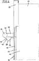
- FIG 2 illustrates a schematic side view of the door handle 20 attached at the oven door 16 of the cooking oven 10 according to the preferred embodiment of the present invention.
- the oven door 16 is in the closed state.
- the front panel 22 is arranged above the oven door 16.
- the door handle 20 is attached at an outer glass panel 30 of the oven door 16.
- the handle adapters 26 are directly attached at the outer glass panel 30.
- the handle bar 24 is attached at the handle adapters 26.
- the electric device 28 is attached at the central portion of the handle bar 24.
- the electric device 28 is arranged inside a housing 34.
- the housing is made of plastics.
- the electric device 28 comprises a camera 36.
- a camera lens 38 of said camera 36 is attached at the housing 34 and directed through the door window 18 of the oven door 16 into the oven cavity 14.
- the camera lens 38 is arranged substantially in the centre of the door handle 20, so that the complete oven cavity 14 is visible by said camera lens 38.
- the electric device 28 comprises an LED display 40 arranged substantially at the front side of the door handle 20, and/or an LED indicator.
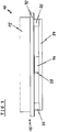
- FIG 3 illustrates a schematic top view of the door handle 20 attached at the oven door 16 of the cooking oven 10 according to the preferred embodiment of the present invention.
- the handle adapters 26 are attached at the outer glass panel 30 of the oven door 16. Each end portion of the handle bar 24 is attached at one of the handle adapters 26.
- the housing 34 is attached at the central portion of the handle bar 24. The housing 34 is substantially arranged between the handle bar 24 and the outer glass panel 30 of the oven door 16.
- the electric device 28 is arranged inside the housing 34.
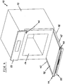
- FIG 4 illustrates a schematic perspective view of the cooking oven 10 according to the preferred embodiment of the present invention.
- the oven door 16 of the cooking oven 10 is open.
- the oven door 16 comprises a door frame including two door columns 42 and a top door frame part 44.
- the top door frame part 44 is removable.
- the cooking oven 10 comprises chassis contact elements 46 and door contact elements 48.
- the chassis contact elements 46 are arranged at a front frame enclosing the oven cavity 14.
- the door contact elements 48 are arranged at the door frame of the oven door 16. In this example, the door contact elements 48 are arranged at the top door frame part 44.
- the chassis contact elements 46 and the door contact elements 48 are in an electric contact to each other, when the oven door 16 is closed.
- the chassis contact elements 46 are arranged in the right upper corner of the front frame enclosing the oven cavity 14.
- the door contact elements 48 are arranged in the right upper corner of the door frame, when the oven door 16 is in the closed state.
- the chassis contact elements 46 and the door contact elements 48 provide electric contacts between the chassis 12 and the oven door 16, when the oven door 16 is in the closed state.
- a wireless electrical contact or a wireless connection the oven door 16 and the chassis 12 may be provided. This may be realized by wireless energy transfer and without any physical contacts for the transfer of electric current, for example by using inductive coupling between the door 16 and the chassis 12 of the domestic appliance 10.
- a primary coil may be arranged in the chassis 12 and a secondary coil may be part of the oven door 16. The coils are aligned in the operating position in such a way to each other, so that a very high inductive coupling between the primary and secondary coil results. If the door 16 removes from its operating and closed position, with increasing distance of the door 16 and/or increasing tilt angle between the coils, the wireless inductive coupling dissolves.
- additional signals may be transmitted between the oven door 16 and the chassis 12 as well.
- FIG 5 illustrates a schematic perspective view of an upper part of the oven door 16 for the cooking oven 10 according to the preferred embodiment of the present invention.
- the door handle 20 is attached at the outer glass panel 30 of the oven door 16.
- the handle adapters 26 are directly attached at the outer glass panel 30, while the handle bar 24 is attached at the handle adapters 26.
- the electric device 28 is arranged in the central portion of the handle bar 24.
- the electric device 28 includes a network interface unit 50, an LED display 40 and/or an LED indicator 40.
- the handle bar 24 is formed as a hollow profile part. At both ends of the handle bar 24 a plug element 52 is inserted in each case.
- a USB interface 54 is an integrated part of the handle adapter 26 on the left hand side.
- An antenna 56 is an integrated part of the handle adapter 26 on the right hand side.
- the USB interface 54 is a standard type.
- the USB interface 54 may also be arranged inside the housing 34.
- a WLAN stick may be plugged in the USB interface 54 for a data transmission.
- a personal computer may be connected via a USB cable and the USB interface 54 to a control unit of the cooking oven 10.
- this may be advantageous in a service case, because a function of appliance can be checked or a software update can be performed without disassembling the domestic appliance in order to obtain access to the control unit.
- the USB interface 54 may be placed on the top wall of the handle adapter 26, on its side walls, but also in the handle bar 24 as well.
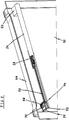
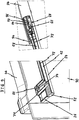
- FIG 6 illustrates a schematic sectional side view of the door handle 20 attached at the oven door 16 of the cooking oven 10 according to the preferred embodiment of the present invention.
- the door handle 20 is attached at the outer glass panel 30 of the oven door 16, wherein the handle adapters 26 are directly attached at the outer glass panel 30, while the handle bar 24 is attached at the handle adapters 26.
- FIG 6 clarifies that the handle bar 24 is formed as the round hollow profile part.
- an inner space 62 is formed in the handle bar 24.
- the electric device 28 is arranged inside said inner space 62 of the handle bar 24 and in the housing 34.
- the electric device 28 includes a network interface unit 50, a WIFI unit 64 and a wiring connector element 66.
- the housing 34 allows the reception of the WIFI unit 64, which is usually bigger than the inner space 62 of the handle bar 24. Further, the housing 34 avoids a direct contact to the handle bar 24 made of metal. Moreover, the housing 34 insures an easy assembling.
- the housing 34 is made of plastic and protects sufficiently the WIFI unit 64 and other components of the electric device 28. Additionally, the housing 34 made of plastic provides an electric isolation for the electric device 28.
- the WIFI unit 64 with the antenna 56 may be placed into at least one of the handle adapter(s) 26, by which the handle bar 24 is fixed to the oven door 16 and/or in the housing 34 fixed to the handle bar 24.
- WIFI units 64 are available on the market as standard modules. The advantage of standard modules is that the ready developed WIFI unit 64 reduces the development effort and the costs.
- the antenna 56 may be placed in the handle adapter 26.
- the antenna 56 is chip or stripe type.
- data can be transmitted by means of a wiring or electric conductors to a WLAN module in the chassis 12.
- one antenna 56 with different characteristics may be placed as well.
- the both antennas 56 are connected by means of wiring which is going through the inner space 62 of the handle bar 24.
- the antenna 56 may be placed in a plastic housing arrangeable in each position of the door handle 20 as well.
- the housing 34 is fixed at the handle bar 24 by a housing screw 58.
- Said housing screw 58 penetrates a screw hole 84 in the housing 34 and a flow drill thread 60 formed in the handle bar 24.
- the flow drill screw technology insures a fixation of the housing screw 58 in the flow drill thread 60 with higher torque values, so that a strong fixation is ensured.
- the flow drill screw technology also simplifies the fixation on the hollow handle bar 24 without using any additional components or tools.
- the electric device 28 includes a touch sensor or a touch dimmer, then the flow drill screw technology ensures a reliable contact between said touch sensor or touch dimmer and the handle bar 24.
- FIG 7 illustrates a schematic exploded perspective view of the door handle 20 for the oven door 16 of the cooking oven 10 according to the preferred embodiment of the present invention.
- the handle bar 24 includes a recess 70 provided for receiving the housing 34.
- the housing 34 includes a clip element 68 for inserting into one face side of the recess 70.
- the housing 34 may be fastened by the housing screw 58, which is insertable into the flow drill thread 60 formed in the handle bar 24.
- the camera lens 38 is attached at the housing 34.
- the housing screw 58 is spaced from the wiring cables 72 and wiring connector elements 66 inside the handle bar 24.
- the handle adapter 26 includes a cable opening 74 at that side, which contacts the oven door 16, while the outer glass panel 30 includes at least one cable opening 88 at opposite.
- a wiring cable 72 extends between the recess 70 of the handle bar 24 on the one hand and the cable opening 74 of the handle adapter 26 and the cable opening 88 of the outer glass panel 30 on the other hand.
- Two wiring connector elements 66 are attached at the ends of the wiring cable 72.
- the wiring connector element 66 in the recess 70 of the handle bar 24 is provided for a connection to the electric device 28 in the housing 34.
- the wiring connector element 66 in the cable opening 74 of the handle adapter 26 provided for penetrating the opening 88, preferably formed as slot hole or hole, in the outer glass panel 30 and a connection behind said outer glass panel 30.
- the open ends of the handle bar 24 formed as the round hollow profile part are filled by the plug elements 52.
- the power supply from the chassis 12 of the domestic appliance 10 or cooking oven 10 to the door or oven door 16, respectively, may be provided by means of the wiring cable 72, by means of wireless inductive technology or by means of electric conductors, which are engaged, when the oven door 16 is closed and disengaged, when said oven door 16 is open.
- the flow drill technology allows the use of relative long screws in very thin walls.
- the use of the flow drill technology allows the very thin material for the handle bar 24, so that the hollow handle bar 24 provides enough inner space 62 for the wiring cables 72 and wiring connector elements 66 inside the handle bar 24.
- FIG 8 illustrates a schematic partial sectional perspective view of the upper part of the oven door 16 for the cooking oven 10 according to the preferred embodiment of the present invention.
- the handle adapters 26 are directly attached at the outer glass panel 30, while the handle bar 24 is attached at the handle adapters 26.
- a handle screw 76 penetrates the outer glass panel, the handle adapter 26 and a thread formed in the plug element 52. After fixing the door handle 20 at the outer glass panel 30, the wiring cable 72 and wiring connector element 66, which is coming out from a rear side of outer glass panel 30, can be connected to an electric connector of the oven door 16.
- another conduction system arranged inside the oven door 16 door can be directly connected to the wiring cable 72 of the door handle 20, for example by means of a plug-in connector element. This contributes also to a very easy exchangeability of the door handle 20.
- FIG 8 clarifies the course of the wiring cable 72 between the electric device 28 on the one hand and the cable opening 74 in the handle adapter 26 as well as the cable opening 88 in the outer glass panel 30 on the other hand.
- the wiring cable 72 from the electric device 28 in the handle bar 24 propagates through the inner space of the hollow profile part of said handle bar 24 up to the handle adapter 26, afterward through the cable opening 74 in the handle adapter 26 and at last through the cable opening 74 in the outer glass panel 30.
- the handle bar 24, the adapter 26, the housing 34, the electric device 28, the wiring cable 72 and wiring connector elements 66 can be preassembled together, and afterward of the door handle 20 is fixed on the outer glass panel 30 of the oven door 16.
- the outer glass panel may be provided with a bigger hole or slot, so that the handle screw 76 for the door handle 20 as well as the wiring cable 72 with the wiring connector element 66 can penetrate said hole or slot, respectively.
- FIG 9 illustrates two scaled up details of the partial sectional perspective view of the upper part of the oven door 16 shown in FIG 8 .
- the first scaled up detail on the left hand side shows the handle screw 76 penetrating the outer glass panel, the handle adapter 26 and the thread formed in the plug element 52.
- the wiring cable 72 penetrates the outer glass panel 30 behind the cable opening 74 in the handle adapter 26.
- the handle adapter 26 acts as a spacer between the handle bar 24 and the outer glass panel 30 of the oven door 16. At least one handle adapter 26 is required as spacer. Preferably, two handle adapters 26 are placed at either ends of the handle bar 24 in order to connect said handle bar 26 to the oven door 16.
- the handle screw 76 penetrates the handle adapters 26 and is fixed in the thread formed in the plug element 52 inserted into the handle bar 24, so that the handle bar 24 and the both handle adapters 26 are fixed by two handle screws 76 all in all.
- the handle adapter 26 can also be fixed to the handle bar 24 at first, and afterward the whole preassembled door handle 20 may be fixed at the oven door 16, e.g. at the outer glass panel 30 of said oven door 16.
- the second scaled up detail on the right hand side shows the electric device 28 partially inside the central portion of the handle bar 24 and partially inside the housing 34.
- the electric device 28 is the network interface unit 50 including the WIFI unit 64, the wiring connector element 66 and the camera 36.
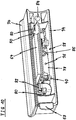
- FIG 10 illustrates a schematic perspective view of the housing 34 for an electric device 28 attachable to the door handle 20 for the oven door 16 of the cooking oven 10 according to the preferred embodiment of the present invention.
- the electric device 28 is partially inside the housing 34.
- the electric device 28 is the network interface unit 50 including a printed circuit board.
- the circuit board of the network interface unit 50 is inserted in and supported by a circuit board guide 80.
- Said circuit board guide 80 is formed within the housing 34.
- the network interface unit 50 includes the WIFI unit 64, the wiring connector element 66, the LED display 40 and/or LED indicator, a light guide 86, the camera 36, a camera module 78 and a circuit board interface 82.
- the clip element 68 is formed at one side of the housing 34, while the screw hole 84 for receiving the housing screw 58 is formed on its opposite side.
- the housing screw 58 penetrates the screw hole 84 in the housing 34 and the flow drill thread 60 formed in the handle bar 24.
- the present invention relates to the door handle 20 for the oven door 16 of the cooking oven 10
- the present invention relates to a door handle for a door of an arbitrary domestic appliance.
Landscapes
- Engineering & Computer Science (AREA)
- Chemical & Material Sciences (AREA)
- Combustion & Propulsion (AREA)
- Mechanical Engineering (AREA)
- General Engineering & Computer Science (AREA)
- Physics & Mathematics (AREA)
- Thermal Sciences (AREA)
- Electric Ovens (AREA)
- Cookers (AREA)
Description
- The present invention relates to a door handle for a door of a domestic appliance according to the preamble of claim 1. In particular, the present invention relates to a door handle for an oven door of a cooking oven. Further, the present invention relates to a door with a door handle for a domestic appliance.
- Moreover, the present invention relates to a domestic appliance including a door with a door handle.
- In a door handle attached at a door of the domestic appliance one or more different electric device can be arranged. In particular, a network interface unit (e.g. WIFI, Bluetooth, iNFC, Zig Bee), a WLAN module, an antenna, a camera, an LED display, various sensors, light guides, displays and/or a projector may be arranged inside the door handle. For example, a digital camera in the door handle of a cooking oven may provide pictures of a foodstuff being cooked inside the oven cavity through a glass window or full glass oven door, wherein said pictures are transmitted via the network interface unit to an external computer or computer network, e.g. to a user's mobile computer device in order to allow remote live visual monitoring of the cooking by the user.
- Furthermore, there are requirements on the market for exchangeable door handles as well as for door handles with more integrated functions. Door handles with some simple features, e.g. integrated LED displays or touch sensors are well known. However, due to the wiring concept and the connection to a power supply, said door handles are not exchangeable by the user. It would be advantageous, that the user could upgrade his domestic appliance or a dedicated furniture with an new door handle, which provides some additional electric features without having replacing the whole domestic appliance.
- Some recent domestic appliances are increasingly being upgraded or developed in order to include WIFI connectivity, so that the domestic appliance is connectable to the internet and exchange information with smartphones or computers of the user. The WIFI module together with the antenna is usually placed into the chassis of the domestic appliance or dedicated furniture. However, it is difficult to find out a suitable place for the WIFI module, because there are temperature limits of about -40°C and +85°C for said WIFI module, while a cooking oven with pyrolytic self-cleaning function is heated up to about 450°C. Often, an additional cooling of the WIFI module would be required.
- Furthermore, it is quite difficult that an antenna arranged inside the chassis provides a good wireless signal with respect to the position and orientation of the WIFI module. If there is a metal casing between a router and WIFI module and its antenna, then said router cannot receive the wireless signal. If the WIFI module is placed on, close to or against a metal part, then problems may occur. The signals can easily propagate through a wood desk or furniture, but metal will obstruct the signals. Further, furniture cabinets, cooking hobs and cooking hoods may also obstruct the signals.
- Furthermore, domestic appliances are usually installed very close to each other. If neighboring domestic appliances are equipped with single WIFI modules, then the signal may be obstruct. Interference from other wireless networks in the area can cause issues with the wireless signal. The lower the distance between WIFI module and router, the better the transmitted signal is. An arrangement of the WIFI module near the router reduces interference and usually provides the best signal. Thus, the WIFI module with the antenna should be placed at the outer part of the domestic appliance or dedicated furniture, but not inside of them.
-
DE 10 2010 003 898 A1 discloses a door handle for a door of a domestic appliance. The door handle comprises a handle bar and two handle adapters. An electric illumination device is arranged within the handle bar. For example, the illumination device enlarges the cross-section of the handle bar. -
DE 10 2009 033 087 A1 discloses a cooling and/or refrigerator apparatus comprising a door with a door handle. The door handle comprises a handle bar and two handle adapters. An electric illumination device is arranged within the handle bar. The illumination device and the handle bar have the same cross-sections. -
US 2012/0127696 A1 discloses a signature lighting system for an appliance. The signature lighting system comprises a carrier, a light guide disposed adjacent the carrier and a light source disposed adjacent the light guide. The light guide is releasably secured in a channel of the carrier by a spring clamp. -
US 2010/0154172 A1 discloses an appliance with a handle assembly. A docking station for a consumer electronic device is arranged at the handle assembly. For example, the consumer electronic device is a network interface unit. -
DE 10 2011 087 753 A1 discloses a door handle comprising a handle bar and two handle adapters. The ends of the handle bar are closed by plug elements. A thread is cut in the plug element by a screw. The handle bar is fastened at a door of a domestic appliance by said screw. -
CN 2 903 851 Y discloses a door with a door handle for a domestic appliance. Cables are arranged inside the door handle and take course through cable openings into the door and a chassis of the domestic appliance. -
WO 2009/023413 A2 discloses an appliance with an electric current conduction system. The electric current conduction system includes a conductor connected to a main body of the appliance and a further conductor connected to a door of said appliance. Electric current is conducted between the conductors, when said conductors are engaged with each other. - It is an object of the present invention to provide a door handle for a door of a domestic appliance, which allows a reliable connection between the domestic appliance and external devices.
- The object is achieved by the door handle according to claim 1.
- According to the present invention at least one antenna and/or USB interface are arranged in or at the handle adapter.
- The main idea of the present invention is the housing removably attached at the handle bar on one hand and the wiring cable inside the handle bar between the electric device and the cable opening of the handle adapter on the other hand. The house allows the installation of different electric features, e.g. network interface unit, WLAN module, antenna, camera, LED display, LED indicator, light guide, different sensors. The wiring cable allows a power and/or signal connection between the electric device and the door. Since the housing is removable, the electric device or components thereof can be easily exchanged. The present invention allows an upgrade without exchanging the whole domestic appliance.
- In particular, the handle bar is made of metal, preferably of aluminium. Aluminium fulfills the modern aesthetical requirements.
- Further, the handle adapter and/or the housing may be made of plastics. The plastic housing provides an electric isolation. Moreover, the housing may be fixable at the handle bar by at least one housing screw and/or at least one clip element, wherein preferably the housing is fixable at the handle bar by one housing screw and one clip element.
- Preferably, the handle bar includes at least one flow drill thread for receiving the housing screw and/or at least one handle screw. The flow drill thread technology allows a thin wall for the handle bar resulting in a large inner space of said handle bar.
- In particular, the electric device comprises at least one network interface unit, wherein preferably said network interface unit includes a WIFI unit, a Bluetooth unit, an iNFC unit and/or a Zig Bee unit.
- Further, the electric device may comprise at least one camera, camera lens, camera module, LED display, antenna, projector, sensor and/or USB interface. These features allow a plurality of applications.
- Preferably, the wiring cable includes one wiring connector element at one end or two wiring connector elements at both ends, wherein preferably said wiring connector element is provided for connecting to the electric device and/or for connecting to a connector element of the door. The wiring connector elements contribute to an easy exchange of the electric device or components thereof.
- Furthermore, the handle bar may comprise at least one plug element, preferably two plug elements, wherein said plug element is provided for closing an end of the handle bar and for receiving a handle screw connecting the handle bar, the handle adapter and/or the door or a front panel of said door. The plug element allows a reliable closing of the handle bar.
- In particular, the recess and the housing are arranged in a central portion of the handle bar, wherein preferably said recess and housing are arrangeable between the handle bar and the door. This contributes to the aesthetical requirements.
- Further, the present invention relates to a door for a domestic appliance, in particular an oven door for a cooking oven, wherein the door comprises the door handle mentioned above. Preferably, the camera lens is directed to a door window of the door, so that a cavity behind the door is within a view field of said camera lens.
- Preferably, the door includes holes for the handle screws and one or more openings, preferably formed as slotted holes, for wiring cables. In particular, the door includes at least one cable opening, preferably formed as slotted hole, for wiring cables, wherein said cable opening is opposite the cable opening of the handle adapter, and wherein preferably the door comprises an outer glass panel including the holes for the handle screws and the cable opening.
- Moreover, the present invention relates to a domestic appliance, in particular a cooking oven, comprising a door and a door handle attached or attachable at said door, wherein the domestic appliance comprises the door handle and/or the door mentioned above.
- At last, the domestic appliance may comprise chassis contact elements and door contact elements being in contact to each other in a closed state of the door, wherein preferably a galvanic or inductive contact occurs between the chassis contact elements and door contact elements.
- Novel and inventive features of the present invention are set forth in the appended claims.
- The present invention will be described in further detail with reference to the drawing, in which
- FIG 1
- illustrates a schematic perspective view of a domestic appliance according to a preferred embodiment of the present invention,
- FIG 2
- illustrates a schematic side view of a door handle attached at an oven door of a cooking oven according to the preferred embodiment of the present invention,
- FIG 3
- illustrates a schematic top view of the door handle attached at the oven door of the cooking oven according to the preferred embodiment of the present invention,
- FIG 4
- illustrates a schematic perspective view of the cooking oven according to the preferred embodiment of the present invention,
- FIG 5
- illustrates a schematic perspective view of an upper part of the oven door for the cooking oven according to the preferred embodiment of the present invention,
- FIG 6
- illustrates a schematic sectional side view of the door handle attached at the oven door of the cooking oven according to the preferred embodiment of the present invention,
- FIG 7
- illustrates a schematic exploded perspective view of the door handle for the oven door of the cooking oven according to the preferred embodiment of the present invention,
- FIG 8
- illustrates a schematic partial sectional perspective view of the upper part of the oven door for the cooking oven according to the preferred embodiment of the present invention,
- FIG 9
- illustrates two scaled up details of the partial sectional perspective view of the upper part of the oven door shown in
FIG 8 , and - FIG 10
- illustrates a schematic perspective view of a housing for an electric device attachable to the door handle for the oven door of the cooking oven according to the preferred embodiment of the present invention.
-
FIG 1 illustrates a schematic perspective view of adomestic appliance 10 according to a preferred embodiment of the present invention. In this embodiment, thedomestic appliance 10 is acooking oven 10. - The
cooking oven 10 comprises achassis 12, anoven cavity 14, anoven door 16 and afront panel 22. Theoven cavity 14 is arranged inside thechassis 12. A front side of theoven cavity 14 is closed by theoven door 16. Thefront panel 22 is arranged above theclosed oven door 16. Theoven door 16 comprises adoor window 18 arranged in a central portion of saidoven door 16. - A
door handle 20 is attached at an outer side of theoven door 16. In this example, thedoor handle 20 is arranged above thedoor window 18. Thedoor handle 20 includes anelongated handle bar 24 and twohandle adapters 26. In this example, thehandle bar 24 of thedoor handle 20 extends horizontally. Thehandle adapters 26 are interconnected between theoven door 16 and one end portion of thehandle bar 24 in each case. Thehandle adapters 26 are attached at the outer side of theoven door 16. In turn, thehandle bar 24 is attached at thehandle adapters 26. In this example, thedoor handle 20 includes twohandle adapters 26. In general, thedoor handle 20 may include one ormore handle adapters 26. - At least one
electric device 28 is arranged inside thehandle bar 24. In this example, theelectric device 28 is arranged inside a central portion of thehandle bar 24. -
FIG 2 illustrates a schematic side view of thedoor handle 20 attached at theoven door 16 of thecooking oven 10 according to the preferred embodiment of the present invention. InFIG 2 theoven door 16 is in the closed state. Thefront panel 22 is arranged above theoven door 16. - The
door handle 20 is attached at anouter glass panel 30 of theoven door 16. Thehandle adapters 26 are directly attached at theouter glass panel 30. In turn, thehandle bar 24 is attached at thehandle adapters 26. Theelectric device 28 is attached at the central portion of thehandle bar 24. Theelectric device 28 is arranged inside ahousing 34. In this example, the housing is made of plastics. Theelectric device 28 comprises acamera 36. Acamera lens 38 of saidcamera 36 is attached at thehousing 34 and directed through thedoor window 18 of theoven door 16 into theoven cavity 14. Preferably, thecamera lens 38 is arranged substantially in the centre of thedoor handle 20, so that thecomplete oven cavity 14 is visible by saidcamera lens 38. Further, theelectric device 28 comprises anLED display 40 arranged substantially at the front side of thedoor handle 20, and/or an LED indicator. -
FIG 3 illustrates a schematic top view of thedoor handle 20 attached at theoven door 16 of thecooking oven 10 according to the preferred embodiment of the present invention. - The
handle adapters 26 are attached at theouter glass panel 30 of theoven door 16. Each end portion of thehandle bar 24 is attached at one of thehandle adapters 26. Thehousing 34 is attached at the central portion of thehandle bar 24. Thehousing 34 is substantially arranged between thehandle bar 24 and theouter glass panel 30 of theoven door 16. Theelectric device 28 is arranged inside thehousing 34. -
FIG 4 illustrates a schematic perspective view of thecooking oven 10 according to the preferred embodiment of the present invention. InFIG 4 theoven door 16 of thecooking oven 10 is open. - The
oven door 16 comprises a door frame including twodoor columns 42 and a topdoor frame part 44. In this example, the topdoor frame part 44 is removable. Further, thecooking oven 10 compriseschassis contact elements 46 anddoor contact elements 48. Thechassis contact elements 46 are arranged at a front frame enclosing theoven cavity 14. Thedoor contact elements 48 are arranged at the door frame of theoven door 16. In this example, thedoor contact elements 48 are arranged at the topdoor frame part 44. - The
chassis contact elements 46 and thedoor contact elements 48 are in an electric contact to each other, when theoven door 16 is closed. In this example, thechassis contact elements 46 are arranged in the right upper corner of the front frame enclosing theoven cavity 14. In a similar way, thedoor contact elements 48 are arranged in the right upper corner of the door frame, when theoven door 16 is in the closed state. Thechassis contact elements 46 and thedoor contact elements 48 provide electric contacts between thechassis 12 and theoven door 16, when theoven door 16 is in the closed state. - When the
chassis contact elements 46 and thedoor contact elements 48 are in contact, then the electric current can flow from the power supply in thechassis 12 to theelectric device 28. Additionally or alternatively, a wireless electrical contact or a wireless connection theoven door 16 and thechassis 12 may be provided. This may be realized by wireless energy transfer and without any physical contacts for the transfer of electric current, for example by using inductive coupling between thedoor 16 and thechassis 12 of thedomestic appliance 10. A primary coil may be arranged in thechassis 12 and a secondary coil may be part of theoven door 16. The coils are aligned in the operating position in such a way to each other, so that a very high inductive coupling between the primary and secondary coil results. If thedoor 16 removes from its operating and closed position, with increasing distance of thedoor 16 and/or increasing tilt angle between the coils, the wireless inductive coupling dissolves. Besides electrical power, additional signals may be transmitted between theoven door 16 and thechassis 12 as well. -
FIG 5 illustrates a schematic perspective view of an upper part of theoven door 16 for thecooking oven 10 according to the preferred embodiment of the present invention. - The
door handle 20 is attached at theouter glass panel 30 of theoven door 16. Thehandle adapters 26 are directly attached at theouter glass panel 30, while thehandle bar 24 is attached at thehandle adapters 26. Theelectric device 28 is arranged in the central portion of thehandle bar 24. In this example, theelectric device 28 includes anetwork interface unit 50, anLED display 40 and/or anLED indicator 40. - The
handle bar 24 is formed as a hollow profile part. At both ends of the handle bar 24 aplug element 52 is inserted in each case. AUSB interface 54 is an integrated part of thehandle adapter 26 on the left hand side. Anantenna 56 is an integrated part of thehandle adapter 26 on the right hand side. - Preferably, the
USB interface 54 is a standard type. TheUSB interface 54 may also be arranged inside thehousing 34. For example, a WLAN stick may be plugged in theUSB interface 54 for a data transmission. Thus, a personal computer may be connected via a USB cable and theUSB interface 54 to a control unit of thecooking oven 10. In particular, this may be advantageous in a service case, because a function of appliance can be checked or a software update can be performed without disassembling the domestic appliance in order to obtain access to the control unit. TheUSB interface 54 may be placed on the top wall of thehandle adapter 26, on its side walls, but also in thehandle bar 24 as well. -
FIG 6 illustrates a schematic sectional side view of thedoor handle 20 attached at theoven door 16 of thecooking oven 10 according to the preferred embodiment of the present invention. - The
door handle 20 is attached at theouter glass panel 30 of theoven door 16, wherein thehandle adapters 26 are directly attached at theouter glass panel 30, while thehandle bar 24 is attached at thehandle adapters 26.FIG 6 clarifies that thehandle bar 24 is formed as the round hollow profile part. Thus, aninner space 62 is formed in thehandle bar 24. Theelectric device 28 is arranged inside saidinner space 62 of thehandle bar 24 and in thehousing 34. In this example, theelectric device 28 includes anetwork interface unit 50, aWIFI unit 64 and awiring connector element 66. - The
housing 34 allows the reception of theWIFI unit 64, which is usually bigger than theinner space 62 of thehandle bar 24. Further, thehousing 34 avoids a direct contact to thehandle bar 24 made of metal. Moreover, thehousing 34 insures an easy assembling. Thehousing 34 is made of plastic and protects sufficiently theWIFI unit 64 and other components of theelectric device 28. Additionally, thehousing 34 made of plastic provides an electric isolation for theelectric device 28. - The
WIFI unit 64 with theantenna 56 may be placed into at least one of the handle adapter(s) 26, by which thehandle bar 24 is fixed to theoven door 16 and/or in thehousing 34 fixed to thehandle bar 24.WIFI units 64 are available on the market as standard modules. The advantage of standard modules is that the ready developedWIFI unit 64 reduces the development effort and the costs. - If the
standard WIFI unit 64 is relative big, then theantenna 56 may be placed in thehandle adapter 26. For example, theantenna 56 is chip or stripe type. In this case, data can be transmitted by means of a wiring or electric conductors to a WLAN module in thechassis 12. In order to obtain best possible signals in each of both handleadapters 26 at either ends of thehandle bar 24 oneantenna 56 with different characteristics may be placed as well. In that case the bothantennas 56 are connected by means of wiring which is going through theinner space 62 of thehandle bar 24. Moreover, theantenna 56 may be placed in a plastic housing arrangeable in each position of thedoor handle 20 as well. - The
housing 34 is fixed at thehandle bar 24 by ahousing screw 58. Saidhousing screw 58 penetrates ascrew hole 84 in thehousing 34 and aflow drill thread 60 formed in thehandle bar 24. - The flow drill screw technology insures a fixation of the
housing screw 58 in theflow drill thread 60 with higher torque values, so that a strong fixation is ensured. The flow drill screw technology also simplifies the fixation on thehollow handle bar 24 without using any additional components or tools. Furthermore, if theelectric device 28 includes a touch sensor or a touch dimmer, then the flow drill screw technology ensures a reliable contact between said touch sensor or touch dimmer and thehandle bar 24. -
FIG 7 illustrates a schematic exploded perspective view of thedoor handle 20 for theoven door 16 of thecooking oven 10 according to the preferred embodiment of the present invention. - In the central portion the
handle bar 24 includes arecess 70 provided for receiving thehousing 34. At one side thehousing 34 includes aclip element 68 for inserting into one face side of therecess 70. At the other side thehousing 34 may be fastened by thehousing screw 58, which is insertable into theflow drill thread 60 formed in thehandle bar 24. Thecamera lens 38 is attached at thehousing 34. - The use of only one
housing screw 58 and theclip element 68 for the fixing thehousing 34 with theelectric device 28 at thehandle bar 24 avoid a possible contact between a further screw and component of theelectric device 28. Preferably, thehousing screw 58 is spaced from thewiring cables 72 andwiring connector elements 66 inside thehandle bar 24. - The
handle adapter 26 includes acable opening 74 at that side, which contacts theoven door 16, while theouter glass panel 30 includes at least onecable opening 88 at opposite. Awiring cable 72 extends between therecess 70 of thehandle bar 24 on the one hand and thecable opening 74 of thehandle adapter 26 and thecable opening 88 of theouter glass panel 30 on the other hand. Two wiringconnector elements 66 are attached at the ends of thewiring cable 72. Thewiring connector element 66 in therecess 70 of thehandle bar 24 is provided for a connection to theelectric device 28 in thehousing 34. Thewiring connector element 66 in thecable opening 74 of thehandle adapter 26 provided for penetrating theopening 88, preferably formed as slot hole or hole, in theouter glass panel 30 and a connection behind saidouter glass panel 30. The open ends of thehandle bar 24 formed as the round hollow profile part are filled by theplug elements 52. - The power supply from the
chassis 12 of thedomestic appliance 10 orcooking oven 10 to the door oroven door 16, respectively, may be provided by means of thewiring cable 72, by means of wireless inductive technology or by means of electric conductors, which are engaged, when theoven door 16 is closed and disengaged, when saidoven door 16 is open. - The flow drill technology allows the use of relative long screws in very thin walls. The use of the flow drill technology allows the very thin material for the
handle bar 24, so that thehollow handle bar 24 provides enoughinner space 62 for thewiring cables 72 andwiring connector elements 66 inside thehandle bar 24. -
FIG 8 illustrates a schematic partial sectional perspective view of the upper part of theoven door 16 for thecooking oven 10 according to the preferred embodiment of the present invention. - The
handle adapters 26 are directly attached at theouter glass panel 30, while thehandle bar 24 is attached at thehandle adapters 26. Ahandle screw 76 penetrates the outer glass panel, thehandle adapter 26 and a thread formed in theplug element 52. After fixing thedoor handle 20 at theouter glass panel 30, thewiring cable 72 andwiring connector element 66, which is coming out from a rear side ofouter glass panel 30, can be connected to an electric connector of theoven door 16. - Further, another conduction system arranged inside the
oven door 16 door can be directly connected to thewiring cable 72 of thedoor handle 20, for example by means of a plug-in connector element. This contributes also to a very easy exchangeability of thedoor handle 20. -
FIG 8 clarifies the course of thewiring cable 72 between theelectric device 28 on the one hand and thecable opening 74 in thehandle adapter 26 as well as thecable opening 88 in theouter glass panel 30 on the other hand. - The
wiring cable 72 from theelectric device 28 in thehandle bar 24 propagates through the inner space of the hollow profile part of saidhandle bar 24 up to thehandle adapter 26, afterward through thecable opening 74 in thehandle adapter 26 and at last through thecable opening 74 in theouter glass panel 30. Thus, thehandle bar 24, theadapter 26, thehousing 34, theelectric device 28, thewiring cable 72 andwiring connector elements 66 can be preassembled together, and afterward of thedoor handle 20 is fixed on theouter glass panel 30 of theoven door 16. In the case of thecooking oven 10, the outer glass panel may be provided with a bigger hole or slot, so that thehandle screw 76 for thedoor handle 20 as well as thewiring cable 72 with thewiring connector element 66 can penetrate said hole or slot, respectively. -
FIG 9 illustrates two scaled up details of the partial sectional perspective view of the upper part of theoven door 16 shown inFIG 8 . - The first scaled up detail on the left hand side shows the
handle screw 76 penetrating the outer glass panel, thehandle adapter 26 and the thread formed in theplug element 52. Thewiring cable 72 penetrates theouter glass panel 30 behind thecable opening 74 in thehandle adapter 26. - The
handle adapter 26 acts as a spacer between thehandle bar 24 and theouter glass panel 30 of theoven door 16. At least onehandle adapter 26 is required as spacer. Preferably, twohandle adapters 26 are placed at either ends of thehandle bar 24 in order to connect saidhandle bar 26 to theoven door 16. In this example, thehandle screw 76 penetrates thehandle adapters 26 and is fixed in the thread formed in theplug element 52 inserted into thehandle bar 24, so that thehandle bar 24 and the both handleadapters 26 are fixed by twohandle screws 76 all in all. Alternatively, thehandle adapter 26 can also be fixed to thehandle bar 24 at first, and afterward the wholepreassembled door handle 20 may be fixed at theoven door 16, e.g. at theouter glass panel 30 of saidoven door 16. - The second scaled up detail on the right hand side shows the
electric device 28 partially inside the central portion of thehandle bar 24 and partially inside thehousing 34. In this example, theelectric device 28 is thenetwork interface unit 50 including theWIFI unit 64, thewiring connector element 66 and thecamera 36. -
FIG 10 illustrates a schematic perspective view of thehousing 34 for anelectric device 28 attachable to thedoor handle 20 for theoven door 16 of thecooking oven 10 according to the preferred embodiment of the present invention. - The
electric device 28 is partially inside thehousing 34. Theelectric device 28 is thenetwork interface unit 50 including a printed circuit board. The circuit board of thenetwork interface unit 50 is inserted in and supported by acircuit board guide 80. Saidcircuit board guide 80 is formed within thehousing 34. Thenetwork interface unit 50 includes theWIFI unit 64, thewiring connector element 66, theLED display 40 and/or LED indicator, alight guide 86, thecamera 36, acamera module 78 and acircuit board interface 82. - The
clip element 68 is formed at one side of thehousing 34, while thescrew hole 84 for receiving thehousing screw 58 is formed on its opposite side. Thehousing screw 58 penetrates thescrew hole 84 in thehousing 34 and theflow drill thread 60 formed in thehandle bar 24. - Although the preferred embodiment of the present invention relates to the
door handle 20 for theoven door 16 of thecooking oven 10, the present invention relates to a door handle for a door of an arbitrary domestic appliance. -
- 10
- domestic appliance, cooking oven
- 12
- chassis
- 14
- oven cavity
- 16
- oven door
- 18
- door window
- 20
- door handle
- 22
- front panel
- 24
- handle bar
- 26
- handle adapter
- 28
- electric device
- 30
- outer glass panel
- 32
- inner glass panel
- 34
- housing
- 36
- camera
- 38
- camera lens
- 40
- LED display
- 42
- door column
- 44
- top door frame part
- 46
- chassis contact elements
- 48
- door contact elements
- 50
- network interface unit
- 52
- plug element
- 54
- USB interface
- 56
- antenna
- 58
- housing screw
- 60
- flow drill thread
- 62
- inner space of the handle bar
- 64
- WIFI unit
- 66
- wiring connector element
- 68
- clip element
- 70
- recess
- 72
- wiring cable
- 74
- cable opening
- 76
- handle screw
- 78
- camera module
- 80
- circuit board guide
- 82
- circuit board interface
- 84
- screw hole
- 86
- light guide
- 88
- cable opening
Claims (15)
- A door handle (20) for a door (16) of a domestic appliance (10), in particular for an oven door (16) of an cooking oven (10), wherein- the door handle (20) comprises an elongated handle bar (24) formed as a hollow profile part or as a pipe,- the door handle (20) comprises at least one handle adapter (26), preferably two handle adapters (26), connectable or connected to the handle bar (24) at its front side and connectable to the door (16) at its rear side,- the door handle (20) comprises at least one housing (34) removably attached at the handle bar (24),- the handle bar (24) includes at least one recess (70) for receiving at least partially the housing (34),- the housing (34) includes an open side facing the recess (70) of the door handle (20), so that an inner space (62) of the door handle (20) is enlarged by said housing (34),- the door handle (20) comprises an electric device (28) arranged or arrangeable inside the housing (34) and/or inside the handle bar (24) next to said housing (34),- the handle adapter (26) includes at least one cable opening (74) at its rear side, and- the door handle (20) comprises at least one wiring cable (72) extending inside the handle bar between the electric device (28) and the cable opening (74) of the handle adapter (26),characterised in that
at least one antenna (56) and/or USB interface (54) are arranged in or at the handle adapter (26). - The door handle according to claim 1,
characterised in that
the handle bar (24) is made of metal, preferably of aluminium. - The door handle according to claim 1 or 2,
characterised in that
the handle adapter (26) and/or the housing (34) are made of plastics. - The door handle according to any one of the preceding claims,
characterised in that
the housing (34) is fixable at the handle bar (24) by at least one housing screw (58) and/or at least one clip element (68), wherein preferably the housing (34) is fixable at the handle bar (24) by one housing screw (58) and one clip element (68). - The door handle according to any one of the preceding claims,
characterised in that
the handle bar (24) includes at least one flow drill thread (60) for receiving the housing screw (58) and/or at least one handle screw (74). - The door handle according to any one of the preceding claims,
characterised in that
the electric device (28) comprises at least one network interface unit (50), wherein preferably said network interface unit (50) includes a WIFI unit (64), a Bluetooth unit, an iNFC unit and/or a Zig Bee unit. - The door handle according to any one of the preceding claims,
characterised in that
the electric device (28) comprises at least one camera (36), camera lens (38), camera module (78), LED display (40), LED indicator (40), light guide (86), antenna (56), projector, sensor and/or USB interface (54). - The door handle according to any one of the preceding claims,
characterised in that
the wiring cable (72) includes one wiring connector element (66) at one end or two wiring connector elements (66) at both ends, wherein preferably said wiring connector element (66) is provided for connecting to the electric device (28) and/or for connecting to a connector element of the door (16) and/or for preparing an electrical grounding of the handle bar (24) to a chassis (12) of the cooking oven (10). - The door handle according to any one of the preceding claims,
characterised in that
the handle bar (24) comprises at least one plug element (52), preferably two plug elements (52), wherein said plug element (52) is provided for closing an end of the handle bar (24), or wherein said plug element (52) is directly pressed into a lateral opening of the door handle (20). - The door handle according to claim 9,
characterised in that
the plug element (52) includes a thread for receiving a handle screw (76) connecting the handle bar (24), the handle adapter (26) and/or the door (16) or a front panel (30) of said door (16). - The door handle according to any one of the preceding claims,
characterised in that
the recess (70) and the housing (34) are arranged in a central portion of the handle bar (24), wherein preferably said recess (70) and housing (34) are arrangeable between the handle bar (24) and the door (16). - A door for a domestic appliance, in particular an oven door (16) for a cooking oven (10), comprising a door handle attached or attachable at said door (16),
characterised in that
the door (16) comprises a door handle (20) according to any one of the claims 1 to 11, wherein preferably the camera lens (38) is directed to a door window (18) of the door (18), so that a cavity (14) behind the door (16) is within a view field of said camera lens (38). - The door according to claim 12,
characterised in that
the door (16) includes holes for the handle screws (76) and at least one cable opening (88), in particular formed as a slotted hole, for wiring cables (72), wherein said cable opening (88) is opposite the cable opening (74) of the handle adapter (26), and wherein preferably the door (16) comprises an outer glass panel (30) including the holes for the handle screws (76) and the cable opening (88). - A domestic appliance, in particular a cooking oven (10), comprising a door (16) and a door handle attached or attachable at said door (16),
characterised in that
the domestic appliance (10) comprises a door handle (20) according any one of the claims 1 to 11 and/or a door (16) according to claim 12 or 13. - The domestic appliance according to claim 14,
characterised in that
the domestic appliance (10) comprises chassis contact elements (46) and door contact elements (48) being in contact to each other in a closed state of the door (16), wherein preferably a galvanic or inductive contact occurs between the chassis contact elements (46) and door contact elements (48) .
Priority Applications (5)
| Application Number | Priority Date | Filing Date | Title |
|---|---|---|---|
| EP15182703.7A EP3136002B1 (en) | 2015-08-27 | 2015-08-27 | Door handle for a door of a domestic appliance |
| AU2016311014A AU2016311014A1 (en) | 2015-08-27 | 2016-07-21 | Door handle for a door of a domestic appliance |
| PCT/EP2016/067360 WO2017032515A1 (en) | 2015-08-27 | 2016-07-21 | Door handle for a door of a domestic appliance |
| BR112018001933A BR112018001933A2 (en) | 2015-08-27 | 2016-07-21 | door handle, door for a household appliance and household appliance |
| US15/741,801 US20180216830A1 (en) | 2015-08-27 | 2016-07-21 | Door handle for a door of a domestic appliance |
Applications Claiming Priority (1)
| Application Number | Priority Date | Filing Date | Title |
|---|---|---|---|
| EP15182703.7A EP3136002B1 (en) | 2015-08-27 | 2015-08-27 | Door handle for a door of a domestic appliance |
Publications (2)
| Publication Number | Publication Date |
|---|---|
| EP3136002A1 EP3136002A1 (en) | 2017-03-01 |
| EP3136002B1 true EP3136002B1 (en) | 2019-07-03 |
Family
ID=54012060
Family Applications (1)
| Application Number | Title | Priority Date | Filing Date |
|---|---|---|---|
| EP15182703.7A Not-in-force EP3136002B1 (en) | 2015-08-27 | 2015-08-27 | Door handle for a door of a domestic appliance |
Country Status (5)
| Country | Link |
|---|---|
| US (1) | US20180216830A1 (en) |
| EP (1) | EP3136002B1 (en) |
| AU (1) | AU2016311014A1 (en) |
| BR (1) | BR112018001933A2 (en) |
| WO (1) | WO2017032515A1 (en) |
Cited By (1)
| Publication number | Priority date | Publication date | Assignee | Title |
|---|---|---|---|---|
| EP4023943A1 (en) | 2020-12-31 | 2022-07-06 | Arçelik Anonim Sirketi | A cooking device comprising a handle and the assembly method thereof |
Families Citing this family (25)
| Publication number | Priority date | Publication date | Assignee | Title |
|---|---|---|---|---|
| AU2015311260B2 (en) * | 2014-09-03 | 2020-02-20 | Electrolux Appliances Aktiebolag | Domestic appliance, in particular cooking oven, with a camera |
| US11104502B2 (en) * | 2016-03-01 | 2021-08-31 | Jeffrey S. Melcher | Multi-function compact appliance and methods for a food or item in a container with a container storage technology |
| EP3299724A1 (en) * | 2016-09-23 | 2018-03-28 | Electrolux Appliances Aktiebolag | Domestic appliance with control plug-in module |
| DE102017202773A1 (en) * | 2017-02-21 | 2018-08-23 | BSH Hausgeräte GmbH | Cooking appliance with a removably designed sensor module |
| DE102017004136A1 (en) * | 2017-05-01 | 2018-11-08 | BSH Hausgeräte GmbH | Household appliance with lighting device for recessed grip |
| WO2019033089A1 (en) | 2017-08-11 | 2019-02-14 | Brava Home, Inc. | Configurable cooking systems and methods |
| EP3450853B1 (en) * | 2017-08-28 | 2021-02-24 | Electrolux Appliances Aktiebolag | Cooking oven with a camera assembly |
| DE102017220888A1 (en) * | 2017-11-22 | 2019-05-23 | BSH Hausgeräte GmbH | Sensor unit for mounting on an outside of a household appliance |
| US10747968B2 (en) | 2017-11-22 | 2020-08-18 | Jeffrey S. Melcher | Wireless device and selective user control and management of a wireless device and data |
| US20210095513A1 (en) * | 2018-04-12 | 2021-04-01 | Electrolux Appliances Aktiebolag | Automatic door for a domestic appliance |
| PL236641B1 (en) | 2018-08-29 | 2021-02-08 | Amica Spolka Akcyjna | Communication system between an oven door and an oven body |
| PL236640B1 (en) | 2018-08-29 | 2021-02-08 | Amica Spolka Akcyjna | Baking oven with a touch door handle |
| US11650628B1 (en) | 2018-10-03 | 2023-05-16 | Anthony, Inc. | Display case door with touch screen |
| US11419434B1 (en) * | 2018-10-03 | 2022-08-23 | Anthony, Inc. | Display case door with door handle camera |
| US11006812B2 (en) | 2018-10-11 | 2021-05-18 | Haier Us Appliance Solutions, Inc. | Status indicator and lighting assembly for an appliance door |
| US11686032B2 (en) * | 2019-04-30 | 2023-06-27 | Whirlpool Corporation | User-interface system for a laundry appliance |
| DE102019206334A1 (en) | 2019-05-03 | 2020-11-05 | BSH Hausgeräte GmbH | Household appliance with energy transmission device |
| DE102019134481A1 (en) * | 2019-12-16 | 2021-06-17 | Miele & Cie. Kg | Home appliance |
| JP7409890B2 (en) * | 2020-01-31 | 2024-01-09 | 東芝ライフスタイル株式会社 | refrigerator |
| EP3879182A1 (en) | 2020-03-10 | 2021-09-15 | Electrolux Appliances Aktiebolag | Camera module |
| US11340853B2 (en) | 2020-04-01 | 2022-05-24 | Anova Applied Electronics, Inc. | Appliance handle with automatic shutoff of input interface elements |
| EP3907431B1 (en) * | 2020-05-04 | 2023-08-16 | Electrolux Appliances Aktiebolag | Door assembly for an oven appliance |
| PL245733B1 (en) * | 2021-06-24 | 2024-09-30 | Wala Spolka Z Ograniczona Odpowiedzialnoscia | Pipe holder with a closing mechanism for the control rod for the element closing the object's opening |
| DE102021213623A1 (en) * | 2021-12-01 | 2023-06-01 | BSH Hausgeräte GmbH | Handle for a door of a household appliance, door and household appliance |
| SI26576A (en) * | 2023-12-19 | 2025-06-30 | Gorenje, d.o.o. | Household appliance comprising a door handle |
Citations (1)
| Publication number | Priority date | Publication date | Assignee | Title |
|---|---|---|---|---|
| WO2010125786A1 (en) * | 2009-04-27 | 2010-11-04 | パナソニック株式会社 | Cooking device |
Family Cites Families (11)
| Publication number | Priority date | Publication date | Assignee | Title |
|---|---|---|---|---|
| EP0828974A1 (en) * | 1996-01-19 | 1998-03-18 | Aktiebolaget Electrolux | A control device for a domestic oven |
| CN2903851Y (en) * | 2006-01-18 | 2007-05-23 | 海尔集团公司 | Refrigerator door handle with illuminating function |
| ITPI20060070A1 (en) * | 2006-06-12 | 2007-12-13 | Studio Carlesi Design | DOOR FOR ELECTRIC APPLIANCES |
| US20090039068A1 (en) * | 2007-08-10 | 2009-02-12 | Electrolux Home Products, Inc. | Electric current conduction system for appliance |
| KR101455861B1 (en) * | 2008-02-21 | 2014-11-03 | 엘지전자 주식회사 | Refrigerator and refrigerator door handle |
| DE102008041519B4 (en) * | 2008-08-25 | 2021-07-29 | BSH Hausgeräte GmbH | Door handle for a door of a household appliance and a door for a household appliance |
| US20100154172A1 (en) * | 2008-12-22 | 2010-06-24 | Whirlpool Corporation | Handle with docking station |
| DE102009033087A1 (en) * | 2009-07-14 | 2011-02-10 | Liebherr-Werk Lienz Gmbh | Refrigerating and/or freezing device, has handle arranged at door or flap and comprising illuminating units that illuminate handle and/or area surrounding handle and are implemented in form of LEDs |
| DE102010003898B4 (en) * | 2010-04-13 | 2024-11-21 | BSH Hausgeräte GmbH | Door handle for a household appliance and door for a household appliance with such a door handle |
| US20120127696A1 (en) * | 2010-11-22 | 2012-05-24 | Visteon Global Technologies, Inc. | Signature lighting system for appliance |
| DE102011087753B4 (en) * | 2011-12-05 | 2021-11-11 | BSH Hausgeräte GmbH | Door handle with handle bracket screwed to a handle profile |
-
2015
- 2015-08-27 EP EP15182703.7A patent/EP3136002B1/en not_active Not-in-force
-
2016
- 2016-07-21 AU AU2016311014A patent/AU2016311014A1/en not_active Abandoned
- 2016-07-21 BR BR112018001933A patent/BR112018001933A2/en not_active Application Discontinuation
- 2016-07-21 US US15/741,801 patent/US20180216830A1/en not_active Abandoned
- 2016-07-21 WO PCT/EP2016/067360 patent/WO2017032515A1/en not_active Ceased
Patent Citations (1)
| Publication number | Priority date | Publication date | Assignee | Title |
|---|---|---|---|---|
| WO2010125786A1 (en) * | 2009-04-27 | 2010-11-04 | パナソニック株式会社 | Cooking device |
Cited By (1)
| Publication number | Priority date | Publication date | Assignee | Title |
|---|---|---|---|---|
| EP4023943A1 (en) | 2020-12-31 | 2022-07-06 | Arçelik Anonim Sirketi | A cooking device comprising a handle and the assembly method thereof |
Also Published As
| Publication number | Publication date |
|---|---|
| BR112018001933A2 (en) | 2018-09-25 |
| US20180216830A1 (en) | 2018-08-02 |
| WO2017032515A1 (en) | 2017-03-02 |
| AU2016311014A1 (en) | 2018-01-18 |
| EP3136002A1 (en) | 2017-03-01 |
Similar Documents
| Publication | Publication Date | Title |
|---|---|---|
| EP3136002A1 (en) | Door handle for a door of a domestic appliance | |
| US9176536B2 (en) | Wireless display for electronic devices | |
| CN203688853U (en) | Optical fiber connector | |
| CN103323920B (en) | Small compact pluggable optical module | |
| AU2013267607B2 (en) | Thermal management of a communication transceiver in an electrical communication device | |
| CN107535063A (en) | Door modules and their use | |
| CN105431802B (en) | Method and apparatus for assigning and imprinting touchpad touch icons | |
| CN110249480B (en) | Embedded type appliance | |
| US8113877B2 (en) | Connector for connecting external antenna | |
| CN113922160B (en) | A kind of power extension plug-in board and socket | |
| US8678862B2 (en) | Homeplug having panel replacement structure | |
| AU2015100773A4 (en) | Dual combined socket and wireless charging apparatus | |
| US20120120612A1 (en) | Routing device for electronic device and method of assembling electronic device | |
| US10423556B2 (en) | KVM extension device self-contained within a video connector | |
| WO2019063305A1 (en) | Communication module for a household appliance | |
| EP3429035B1 (en) | Power cord plug, cable, power cord structure, and electrical device | |
| US20130330947A1 (en) | Homeplug with changeable top case structure | |
| US8891238B2 (en) | Electronic device with detachable communication module | |
| EP3450853B1 (en) | Cooking oven with a camera assembly | |
| CN205807533U (en) | A kind of microwave oven of band APP module | |
| RU2583999C1 (en) | Connection sensor for identifying port of switching panel | |
| US20040155027A1 (en) | Oven controller structure | |
| CA3138469A1 (en) | Single-board computer cartridge | |
| CN108039611B (en) | Socket structure and intelligent socket | |
| CN105030077A (en) | An electric oven under Z-Wave wireless control |
Legal Events
| Date | Code | Title | Description |
|---|---|---|---|
| PUAI | Public reference made under article 153(3) epc to a published international application that has entered the european phase |
Free format text: ORIGINAL CODE: 0009012 |
|
| STAA | Information on the status of an ep patent application or granted ep patent |
Free format text: STATUS: THE APPLICATION HAS BEEN PUBLISHED |
|
| AK | Designated contracting states |
Kind code of ref document: A1 Designated state(s): AL AT BE BG CH CY CZ DE DK EE ES FI FR GB GR HR HU IE IS IT LI LT LU LV MC MK MT NL NO PL PT RO RS SE SI SK SM TR |
|
| AX | Request for extension of the european patent |
Extension state: BA ME |
|
| STAA | Information on the status of an ep patent application or granted ep patent |
Free format text: STATUS: REQUEST FOR EXAMINATION WAS MADE |
|
| 17P | Request for examination filed |
Effective date: 20170901 |
|
| RBV | Designated contracting states (corrected) |
Designated state(s): AL AT BE BG CH CY CZ DE DK EE ES FI FR GB GR HR HU IE IS IT LI LT LU LV MC MK MT NL NO PL PT RO RS SE SI SK SM TR |
|
| GRAP | Despatch of communication of intention to grant a patent |
Free format text: ORIGINAL CODE: EPIDOSNIGR1 |
|
| STAA | Information on the status of an ep patent application or granted ep patent |
Free format text: STATUS: GRANT OF PATENT IS INTENDED |
|
| RIC1 | Information provided on ipc code assigned before grant |
Ipc: F25D 23/02 20060101ALI20180830BHEP Ipc: F24C 15/02 20060101ALI20180830BHEP Ipc: F24C 7/08 20060101AFI20180830BHEP Ipc: F25D 29/00 20060101ALI20180830BHEP |
|
| INTG | Intention to grant announced |
Effective date: 20180919 |
|
| GRAJ | Information related to disapproval of communication of intention to grant by the applicant or resumption of examination proceedings by the epo deleted |
Free format text: ORIGINAL CODE: EPIDOSDIGR1 |
|
| STAA | Information on the status of an ep patent application or granted ep patent |
Free format text: STATUS: REQUEST FOR EXAMINATION WAS MADE |
|
| GRAP | Despatch of communication of intention to grant a patent |
Free format text: ORIGINAL CODE: EPIDOSNIGR1 |
|
| STAA | Information on the status of an ep patent application or granted ep patent |
Free format text: STATUS: GRANT OF PATENT IS INTENDED |
|
| INTC | Intention to grant announced (deleted) | ||
| INTG | Intention to grant announced |
Effective date: 20190206 |
|
| GRAS | Grant fee paid |
Free format text: ORIGINAL CODE: EPIDOSNIGR3 |
|
| GRAA | (expected) grant |
Free format text: ORIGINAL CODE: 0009210 |
|
| STAA | Information on the status of an ep patent application or granted ep patent |
Free format text: STATUS: THE PATENT HAS BEEN GRANTED |
|
| AK | Designated contracting states |
Kind code of ref document: B1 Designated state(s): AL AT BE BG CH CY CZ DE DK EE ES FI FR GB GR HR HU IE IS IT LI LT LU LV MC MK MT NL NO PL PT RO RS SE SI SK SM TR |
|
| REG | Reference to a national code |
Ref country code: GB Ref legal event code: FG4D |
|
| REG | Reference to a national code |
Ref country code: CH Ref legal event code: EP Ref country code: AT Ref legal event code: REF Ref document number: 1151482 Country of ref document: AT Kind code of ref document: T Effective date: 20190715 |
|
| REG | Reference to a national code |
Ref country code: DE Ref legal event code: R096 Ref document number: 602015033023 Country of ref document: DE |
|
| REG | Reference to a national code |
Ref country code: IE Ref legal event code: FG4D |
|
| PGFP | Annual fee paid to national office [announced via postgrant information from national office to epo] |
Ref country code: DE Payment date: 20190830 Year of fee payment: 5 Ref country code: FR Payment date: 20190830 Year of fee payment: 5 |
|
| REG | Reference to a national code |
Ref country code: NL Ref legal event code: MP Effective date: 20190703 |
|
| REG | Reference to a national code |
Ref country code: LT Ref legal event code: MG4D |
|
| PGFP | Annual fee paid to national office [announced via postgrant information from national office to epo] |
Ref country code: GB Payment date: 20190830 Year of fee payment: 5 |
|
| REG | Reference to a national code |
Ref country code: AT Ref legal event code: MK05 Ref document number: 1151482 Country of ref document: AT Kind code of ref document: T Effective date: 20190703 |
|
| PG25 | Lapsed in a contracting state [announced via postgrant information from national office to epo] |
Ref country code: FI Free format text: LAPSE BECAUSE OF FAILURE TO SUBMIT A TRANSLATION OF THE DESCRIPTION OR TO PAY THE FEE WITHIN THE PRESCRIBED TIME-LIMIT Effective date: 20190703 Ref country code: CZ Free format text: LAPSE BECAUSE OF FAILURE TO SUBMIT A TRANSLATION OF THE DESCRIPTION OR TO PAY THE FEE WITHIN THE PRESCRIBED TIME-LIMIT Effective date: 20190703 Ref country code: AT Free format text: LAPSE BECAUSE OF FAILURE TO SUBMIT A TRANSLATION OF THE DESCRIPTION OR TO PAY THE FEE WITHIN THE PRESCRIBED TIME-LIMIT Effective date: 20190703 Ref country code: NO Free format text: LAPSE BECAUSE OF FAILURE TO SUBMIT A TRANSLATION OF THE DESCRIPTION OR TO PAY THE FEE WITHIN THE PRESCRIBED TIME-LIMIT Effective date: 20191003 Ref country code: NL Free format text: LAPSE BECAUSE OF FAILURE TO SUBMIT A TRANSLATION OF THE DESCRIPTION OR TO PAY THE FEE WITHIN THE PRESCRIBED TIME-LIMIT Effective date: 20190703 Ref country code: SE Free format text: LAPSE BECAUSE OF FAILURE TO SUBMIT A TRANSLATION OF THE DESCRIPTION OR TO PAY THE FEE WITHIN THE PRESCRIBED TIME-LIMIT Effective date: 20190703 Ref country code: PT Free format text: LAPSE BECAUSE OF FAILURE TO SUBMIT A TRANSLATION OF THE DESCRIPTION OR TO PAY THE FEE WITHIN THE PRESCRIBED TIME-LIMIT Effective date: 20191104 Ref country code: BG Free format text: LAPSE BECAUSE OF FAILURE TO SUBMIT A TRANSLATION OF THE DESCRIPTION OR TO PAY THE FEE WITHIN THE PRESCRIBED TIME-LIMIT Effective date: 20191003 Ref country code: LT Free format text: LAPSE BECAUSE OF FAILURE TO SUBMIT A TRANSLATION OF THE DESCRIPTION OR TO PAY THE FEE WITHIN THE PRESCRIBED TIME-LIMIT Effective date: 20190703 Ref country code: HR Free format text: LAPSE BECAUSE OF FAILURE TO SUBMIT A TRANSLATION OF THE DESCRIPTION OR TO PAY THE FEE WITHIN THE PRESCRIBED TIME-LIMIT Effective date: 20190703 |
|
| PG25 | Lapsed in a contracting state [announced via postgrant information from national office to epo] |
Ref country code: RS Free format text: LAPSE BECAUSE OF FAILURE TO SUBMIT A TRANSLATION OF THE DESCRIPTION OR TO PAY THE FEE WITHIN THE PRESCRIBED TIME-LIMIT Effective date: 20190703 Ref country code: IS Free format text: LAPSE BECAUSE OF FAILURE TO SUBMIT A TRANSLATION OF THE DESCRIPTION OR TO PAY THE FEE WITHIN THE PRESCRIBED TIME-LIMIT Effective date: 20191103 Ref country code: AL Free format text: LAPSE BECAUSE OF FAILURE TO SUBMIT A TRANSLATION OF THE DESCRIPTION OR TO PAY THE FEE WITHIN THE PRESCRIBED TIME-LIMIT Effective date: 20190703 Ref country code: ES Free format text: LAPSE BECAUSE OF FAILURE TO SUBMIT A TRANSLATION OF THE DESCRIPTION OR TO PAY THE FEE WITHIN THE PRESCRIBED TIME-LIMIT Effective date: 20190703 Ref country code: GR Free format text: LAPSE BECAUSE OF FAILURE TO SUBMIT A TRANSLATION OF THE DESCRIPTION OR TO PAY THE FEE WITHIN THE PRESCRIBED TIME-LIMIT Effective date: 20191004 Ref country code: LV Free format text: LAPSE BECAUSE OF FAILURE TO SUBMIT A TRANSLATION OF THE DESCRIPTION OR TO PAY THE FEE WITHIN THE PRESCRIBED TIME-LIMIT Effective date: 20190703 |
|
| PG25 | Lapsed in a contracting state [announced via postgrant information from national office to epo] |
Ref country code: TR Free format text: LAPSE BECAUSE OF FAILURE TO SUBMIT A TRANSLATION OF THE DESCRIPTION OR TO PAY THE FEE WITHIN THE PRESCRIBED TIME-LIMIT Effective date: 20190703 |
|
| PG25 | Lapsed in a contracting state [announced via postgrant information from national office to epo] |
Ref country code: EE Free format text: LAPSE BECAUSE OF FAILURE TO SUBMIT A TRANSLATION OF THE DESCRIPTION OR TO PAY THE FEE WITHIN THE PRESCRIBED TIME-LIMIT Effective date: 20190703 Ref country code: PL Free format text: LAPSE BECAUSE OF FAILURE TO SUBMIT A TRANSLATION OF THE DESCRIPTION OR TO PAY THE FEE WITHIN THE PRESCRIBED TIME-LIMIT Effective date: 20190703 Ref country code: DK Free format text: LAPSE BECAUSE OF FAILURE TO SUBMIT A TRANSLATION OF THE DESCRIPTION OR TO PAY THE FEE WITHIN THE PRESCRIBED TIME-LIMIT Effective date: 20190703 Ref country code: RO Free format text: LAPSE BECAUSE OF FAILURE TO SUBMIT A TRANSLATION OF THE DESCRIPTION OR TO PAY THE FEE WITHIN THE PRESCRIBED TIME-LIMIT Effective date: 20190703 |
|
| PG25 | Lapsed in a contracting state [announced via postgrant information from national office to epo] |
Ref country code: LU Free format text: LAPSE BECAUSE OF NON-PAYMENT OF DUE FEES Effective date: 20190827 Ref country code: SK Free format text: LAPSE BECAUSE OF FAILURE TO SUBMIT A TRANSLATION OF THE DESCRIPTION OR TO PAY THE FEE WITHIN THE PRESCRIBED TIME-LIMIT Effective date: 20190703 Ref country code: IS Free format text: LAPSE BECAUSE OF FAILURE TO SUBMIT A TRANSLATION OF THE DESCRIPTION OR TO PAY THE FEE WITHIN THE PRESCRIBED TIME-LIMIT Effective date: 20200224 Ref country code: SM Free format text: LAPSE BECAUSE OF FAILURE TO SUBMIT A TRANSLATION OF THE DESCRIPTION OR TO PAY THE FEE WITHIN THE PRESCRIBED TIME-LIMIT Effective date: 20190703 Ref country code: CH Free format text: LAPSE BECAUSE OF NON-PAYMENT OF DUE FEES Effective date: 20190831 Ref country code: LI Free format text: LAPSE BECAUSE OF NON-PAYMENT OF DUE FEES Effective date: 20190831 Ref country code: MC Free format text: LAPSE BECAUSE OF FAILURE TO SUBMIT A TRANSLATION OF THE DESCRIPTION OR TO PAY THE FEE WITHIN THE PRESCRIBED TIME-LIMIT Effective date: 20190703 |
|
| REG | Reference to a national code |
Ref country code: BE Ref legal event code: MM Effective date: 20190831 |
|
| REG | Reference to a national code |
Ref country code: DE Ref legal event code: R097 Ref document number: 602015033023 Country of ref document: DE |
|
| PLBE | No opposition filed within time limit |
Free format text: ORIGINAL CODE: 0009261 |
|
| STAA | Information on the status of an ep patent application or granted ep patent |
Free format text: STATUS: NO OPPOSITION FILED WITHIN TIME LIMIT |
|
| PG2D | Information on lapse in contracting state deleted |
Ref country code: IS |
|
| PG25 | Lapsed in a contracting state [announced via postgrant information from national office to epo] |
Ref country code: IE Free format text: LAPSE BECAUSE OF NON-PAYMENT OF DUE FEES Effective date: 20190827 |
|
| 26N | No opposition filed |
Effective date: 20200603 |
|
| PG25 | Lapsed in a contracting state [announced via postgrant information from national office to epo] |
Ref country code: SI Free format text: LAPSE BECAUSE OF FAILURE TO SUBMIT A TRANSLATION OF THE DESCRIPTION OR TO PAY THE FEE WITHIN THE PRESCRIBED TIME-LIMIT Effective date: 20190703 Ref country code: BE Free format text: LAPSE BECAUSE OF NON-PAYMENT OF DUE FEES Effective date: 20190831 |
|
| REG | Reference to a national code |
Ref country code: DE Ref legal event code: R119 Ref document number: 602015033023 Country of ref document: DE |
|
| GBPC | Gb: european patent ceased through non-payment of renewal fee |
Effective date: 20200827 |
|
| PG25 | Lapsed in a contracting state [announced via postgrant information from national office to epo] |
Ref country code: CY Free format text: LAPSE BECAUSE OF FAILURE TO SUBMIT A TRANSLATION OF THE DESCRIPTION OR TO PAY THE FEE WITHIN THE PRESCRIBED TIME-LIMIT Effective date: 20190703 |
|
| PG25 | Lapsed in a contracting state [announced via postgrant information from national office to epo] |
Ref country code: HU Free format text: LAPSE BECAUSE OF FAILURE TO SUBMIT A TRANSLATION OF THE DESCRIPTION OR TO PAY THE FEE WITHIN THE PRESCRIBED TIME-LIMIT; INVALID AB INITIO Effective date: 20150827 Ref country code: MT Free format text: LAPSE BECAUSE OF FAILURE TO SUBMIT A TRANSLATION OF THE DESCRIPTION OR TO PAY THE FEE WITHIN THE PRESCRIBED TIME-LIMIT Effective date: 20190703 Ref country code: DE Free format text: LAPSE BECAUSE OF NON-PAYMENT OF DUE FEES Effective date: 20210302 Ref country code: FR Free format text: LAPSE BECAUSE OF NON-PAYMENT OF DUE FEES Effective date: 20200831 |
|
| PG25 | Lapsed in a contracting state [announced via postgrant information from national office to epo] |
Ref country code: GB Free format text: LAPSE BECAUSE OF NON-PAYMENT OF DUE FEES Effective date: 20200827 |
|
| PG25 | Lapsed in a contracting state [announced via postgrant information from national office to epo] |
Ref country code: MK Free format text: LAPSE BECAUSE OF FAILURE TO SUBMIT A TRANSLATION OF THE DESCRIPTION OR TO PAY THE FEE WITHIN THE PRESCRIBED TIME-LIMIT Effective date: 20190703 |
|
| PGFP | Annual fee paid to national office [announced via postgrant information from national office to epo] |
Ref country code: IT Payment date: 20220825 Year of fee payment: 8 |
|
| P01 | Opt-out of the competence of the unified patent court (upc) registered |
Effective date: 20230625 |
|
| PG25 | Lapsed in a contracting state [announced via postgrant information from national office to epo] |
Ref country code: IT Free format text: LAPSE BECAUSE OF NON-PAYMENT OF DUE FEES Effective date: 20230827 |