EP3135946A1 - Caliper device and disc brake device including the same - Google Patents
Caliper device and disc brake device including the same Download PDFInfo
- Publication number
- EP3135946A1 EP3135946A1 EP16185318.9A EP16185318A EP3135946A1 EP 3135946 A1 EP3135946 A1 EP 3135946A1 EP 16185318 A EP16185318 A EP 16185318A EP 3135946 A1 EP3135946 A1 EP 3135946A1
- Authority
- EP
- European Patent Office
- Prior art keywords
- brake
- arm
- friction
- pivot shaft
- caliper device
- Prior art date
- Legal status (The legal status is an assumption and is not a legal conclusion. Google has not performed a legal analysis and makes no representation as to the accuracy of the status listed.)
- Granted
Links
- 230000007246 mechanism Effects 0.000 claims abstract description 288
- 238000003825 pressing Methods 0.000 claims description 70
- 238000003780 insertion Methods 0.000 claims description 33
- 230000037431 insertion Effects 0.000 claims description 33
- 230000008878 coupling Effects 0.000 claims description 11
- 238000010168 coupling process Methods 0.000 claims description 11
- 238000005859 coupling reaction Methods 0.000 claims description 11
- 239000012530 fluid Substances 0.000 claims description 7
- 230000004048 modification Effects 0.000 description 28
- 238000012986 modification Methods 0.000 description 28
- 238000007789 sealing Methods 0.000 description 21
- 238000000034 method Methods 0.000 description 11
- 238000009423 ventilation Methods 0.000 description 9
- 230000000694 effects Effects 0.000 description 8
- 230000008569 process Effects 0.000 description 7
- 239000000126 substance Substances 0.000 description 6
- 230000003247 decreasing effect Effects 0.000 description 5
- 230000009471 action Effects 0.000 description 2
- 239000004519 grease Substances 0.000 description 2
- 239000000314 lubricant Substances 0.000 description 2
- 238000004026 adhesive bonding Methods 0.000 description 1
- 230000008859 change Effects 0.000 description 1
- 238000006073 displacement reaction Methods 0.000 description 1
- 239000000463 material Substances 0.000 description 1
- 230000004044 response Effects 0.000 description 1
- 238000003466 welding Methods 0.000 description 1
Images


Classifications
-
- F—MECHANICAL ENGINEERING; LIGHTING; HEATING; WEAPONS; BLASTING
- F16—ENGINEERING ELEMENTS AND UNITS; GENERAL MEASURES FOR PRODUCING AND MAINTAINING EFFECTIVE FUNCTIONING OF MACHINES OR INSTALLATIONS; THERMAL INSULATION IN GENERAL
- F16D—COUPLINGS FOR TRANSMITTING ROTATION; CLUTCHES; BRAKES
- F16D65/00—Parts or details
- F16D65/0006—Noise or vibration control
-
- B—PERFORMING OPERATIONS; TRANSPORTING
- B61—RAILWAYS
- B61H—BRAKES OR OTHER RETARDING DEVICES SPECIALLY ADAPTED FOR RAIL VEHICLES; ARRANGEMENT OR DISPOSITION THEREOF IN RAIL VEHICLES
- B61H5/00—Applications or arrangements of brakes with substantially radial braking surfaces pressed together in axial direction, e.g. disc brakes
-
- F—MECHANICAL ENGINEERING; LIGHTING; HEATING; WEAPONS; BLASTING
- F16—ENGINEERING ELEMENTS AND UNITS; GENERAL MEASURES FOR PRODUCING AND MAINTAINING EFFECTIVE FUNCTIONING OF MACHINES OR INSTALLATIONS; THERMAL INSULATION IN GENERAL
- F16D—COUPLINGS FOR TRANSMITTING ROTATION; CLUTCHES; BRAKES
- F16D55/00—Brakes with substantially-radial braking surfaces pressed together in axial direction, e.g. disc brakes
- F16D55/02—Brakes with substantially-radial braking surfaces pressed together in axial direction, e.g. disc brakes with axially-movable discs or pads pressed against axially-located rotating members
- F16D55/22—Brakes with substantially-radial braking surfaces pressed together in axial direction, e.g. disc brakes with axially-movable discs or pads pressed against axially-located rotating members by clamping an axially-located rotating disc between movable braking members, e.g. movable brake discs or brake pads
- F16D55/224—Brakes with substantially-radial braking surfaces pressed together in axial direction, e.g. disc brakes with axially-movable discs or pads pressed against axially-located rotating members by clamping an axially-located rotating disc between movable braking members, e.g. movable brake discs or brake pads with a common actuating member for the braking members
- F16D55/2245—Brakes with substantially-radial braking surfaces pressed together in axial direction, e.g. disc brakes with axially-movable discs or pads pressed against axially-located rotating members by clamping an axially-located rotating disc between movable braking members, e.g. movable brake discs or brake pads with a common actuating member for the braking members in which the common actuating member acts on two levers carrying the braking members, e.g. tong-type brakes
-
- F—MECHANICAL ENGINEERING; LIGHTING; HEATING; WEAPONS; BLASTING
- F16—ENGINEERING ELEMENTS AND UNITS; GENERAL MEASURES FOR PRODUCING AND MAINTAINING EFFECTIVE FUNCTIONING OF MACHINES OR INSTALLATIONS; THERMAL INSULATION IN GENERAL
- F16D—COUPLINGS FOR TRANSMITTING ROTATION; CLUTCHES; BRAKES
- F16D65/00—Parts or details
- F16D65/005—Components of axially engaging brakes not otherwise provided for
- F16D65/0068—Brake calipers
-
- F—MECHANICAL ENGINEERING; LIGHTING; HEATING; WEAPONS; BLASTING
- F16—ENGINEERING ELEMENTS AND UNITS; GENERAL MEASURES FOR PRODUCING AND MAINTAINING EFFECTIVE FUNCTIONING OF MACHINES OR INSTALLATIONS; THERMAL INSULATION IN GENERAL
- F16D—COUPLINGS FOR TRANSMITTING ROTATION; CLUTCHES; BRAKES
- F16D55/00—Brakes with substantially-radial braking surfaces pressed together in axial direction, e.g. disc brakes
- F16D2055/0004—Parts or details of disc brakes
- F16D2055/0016—Brake calipers
Definitions
- the present invention relates to a caliper device and a brake device including the same.
- a disc brake device that applies a braking force to a wheel by forcing a brake shoe(s) against a disc rotor which rotates together with an axle supporting the wheel of a railroad car has been known.
- a typical disc brake device may include a caliper device.
- the caliper device may include a driving mechanism that drives the brake shoe hydraulically or pneumatically and a brake arm that is coupled to the driving mechanism and swings around an arm pivot shaft such that the brake shoe is displaced close to or away from the disc rotor by the driving mechanism (see, for example, Japanese Patent Application Publication No. 2010-164183 (the "'183 Publication”)).
- the disc brake device (or the caliper device provided therein) disclosed in the '183 Publication includes a friction mechanism that is configured to prevent a brake shoe mount from rocking freely with respect to the brake arm.
- vibration generated when a railroad car travels is transmitted to a caliper device. Therefore in a conventional caliper device, the vibration is also transmitted to the brake arm and the brake shoe mount and consequently the vibration may swings the brake arm and the brake shoe mount.
- the conventional caliper device does not apply braking force to a wheel, the disc rotor and the brake shoe are supposed to be separated from each other but the vibration transmitted to the caliper device may cause the brake shoe to contact with the disc rotor repeatedly. Such contacts may result in noise and failure of the brake shoe.
- the friction mechanism restricts the swinging movements of the brake shoe mount so that the frequency of the brake shoe's contacts with the disc rotor can be reduced.
- One object of the invention is to provide a caliper device and a disc brake device equipped with a new structure that decrease a frequency of brake shoe's contacts with a rotor.
- This disc brake device can obtain the same advantageous effects as those described above in (1)-(26).
- a caliper device and a disc brake device in which the frequency of contacts between a brake shoe and a disc rotor can be decreased.
- a disc brake device 10 may be attached to a truck 3 that supports a chassis 2 of a railroad car 1.
- the disc brake device 10 is forced against a disc rotor 6 rotating together with an axle 5 that rotates a wheel 4 of the truck 3. In this manner, a braking force is applied to the wheel 4.
- the disc brake device 10 may include an air ventilation unit 11 as a fluid system, and at least one caliper device 20 that is fluidically coupled to the air ventilation unit 11.
- the air ventilation unit 11 may be attached to, for example, the truck 3 to provide compressed air to the caliper device 20.
- the caliper device 20 presses the disc rotor 6 attached to, for example, the axle 5 with the compressed air.
- a single air ventilation unit 11 may be fluidically coupled to a plurality of the caliper devices 20. When a braking force is applied to the wheel 4, the air ventilation unit 11 provides compressed air to the caliper device(s) 20.
- the air ventilation unit 11 exhausts the compressed air from the caliper device(s) 20.
- the disc brake device 10 may operate the caliper device(s) 20 by providing a gas other than the compressed air or other fluid such as hydraulic fluid to the caliper device(s) 20, instead of the compressed air provided by the air ventilation unit 11.
- the caliper device 20 may include a main body 30 attached to the truck 3 (see Fig. 1 ), and a first brake arm 40 and a second brake arm 50 that are provided swingably with respect to the main body 30.
- the main body 30 may include an bottom 31 A and an arm support portion 31.
- the arm support portion 31 may include first and second arm portions 31 B, 31C that extend continuously from each side of the bottom 31A to form a substantially U-shape.
- the bottom 31A may have an attached portion 32 where is to be attached to the truck 3 with four bolts (not shown) and that extends opposite to the first and second arm portions 31B, 31C.
- the first and second arm portions 31B, 31C correspond to an shaft support portion.
- the first brake arm 40 may be coupled to the first arm portion 31 B with an arm pivot shaft 21A that has a pivot axis CD1.
- the arm pivot shaft 21A may be able to revolve relative to the first arm portion 31 B but not able to revolve relative to the first brake arm 40.
- a pair of arms 41 of the first brake arm 40 may be separated from each other in the axial direction of the arm pivot shaft 21A and extend such that the arms 41 face to each other.
- An insertion portion 42 through which the arm pivot shaft 21A is inserted may be formed in each arm 41.
- a key member 27A may be inserted between the arm pivot shaft 21A and one of the insertion portions 42. In this manner, a relative rotation between the arm pivot shaft 21A and the first brake arm 40 may be inhibited.
- a washer 28A that covers an end face of the arm pivot shaft 21 A in its axial direction and an end face of the insertion portion 42 may be fixed to the arm pivot shaft 21A with a bolt 29A. Thereby it is possible to prevent the key member 27A from falling off between the arm pivot shaft 21A and the insertion portion 42.
- Each arm 41 may include an output portion 43 that extends from the insertion portion 42, and an input portion 44 that extends from the insertion portion 42 in a direction different from the output portion 43 (the opposite direction in the embodiment).
- a tip coupling portion 45 that couples the pair of arms 41 to each other may be formed.
- a first brake shoe mount 60 may be coupled at the tip portion of the output portion 43 with a brake shoe pivot shaft 22A that has a pivot axis CB1 such that it moves swingably with respect to the output portion 43.
- the brake shoe pivot shaft 22A may be inserted into a pair of supporting portions 62 of the first brake shoe mount 60 and the tip coupling portion 45 of the first brake arm 40.
- the brake shoe pivot shaft 22A may be fixed to the tip coupling portion 45 with a bolt 23A such that the shaft 22A is unrotatable with respect to the tip coupling portion 45 and the shaft 22A may be also supported by a pair of supporting portions 62 such that it is rotatable with respect to the supporting portions 62.
- the second brake arm 50 may be coupled to the second arm portion 31C with an arm pivot shaft 21 B that has a pivot axis CD2.
- the arm pivot shaft 21 B may be able to revolve relative to the second arm portion 31C but not able to revolve relative to the second brake arm 50.
- a pair of arms 51 of the second brake arm 50 may have the same configuration as the pair of arms 41 of the first brake arm 40, and components of the second brake arm 50 are designated by the like reference numerals of the corresponding components of the first brake arm 40 such that the digit "4" in the tens place is replaced by "5".
- a key member 27B may be inserted between the arm pivot shaft 21 B and an insertion portion 52 of the second brake arm 50. In this manner, a relative rotation between the arm pivot shaft 21 B and the second brake arm 50 may be inhibited.
- a washer 28B may be fixed to the end portion of the arm pivot shaft 21 B in the axial direction with a bolt 29B. Thereby it is possible to prevent the key member 27B from falling off between the arm pivot shaft 21B and the insertion portion 52.
- a second brake shoe mount 70 may be coupled at the tip portion of the output portion 53 with a brake shoe pivot shaft 22B that has a pivot axis CB2 such that it moves swingably with respect to the output portion 53.
- the brake shoe pivot shaft 22B may be inserted into a pair of supporting portions 72 of the second brake shoe mount 70 and the tip coupling portion 55 of the second brake arm 50.
- the brake shoe pivot shaft 22B may be fixed to the tip coupling portion 55 with a bolt 23B such that the shaft 22B is unrotatable with respect to the tip coupling portion 55 and the shaft 22A may be also supported by a pair of supporting portions 72 such that it is rotatable with respect to the supporting portions 72.
- the first brake arm 40 and the second brake arm 50 may be disposed at each side of the disc rotor 6 in the thickness direction of the disc rotor 6.
- the first brake shoe mount 60 and the second brake shoe mount 70 may be disposed to face the disc rotor 6 respectively in the thickness direction of the disc rotor 6.
- Brake shoes 61, 71 that are pressed and applied onto the disc rotor 6 may be attached to the brake shoe mount 60, 70 respectively.
- a driving mechanism 80 may be attached to the tip portions of the input portions 44, 54 of the brake arms 40, 50 through fixing shafts 24A, 24B.
- the fixing shafts 24A, 248 may be fixed to the input portions 44, 54 and may be rotatably coupled to the driving mechanism 80. Accordingly the brake arms 40, 50 are able to swing with respect to the driving mechanism 80.
- the driving mechanism 80 may impart a driving force to the input portions 44, 54 in response to compressed air provided from the air ventilation unit 11 (see Fig. 1 ) such that the tip portions of the input portions 44, 54 (fixing shafts 24A, 24B) are separated from each other.
- the driving mechanism 80 may include a return spring (not shown) that imparts, to the input portions 44, 54, a force that separates the brake shoe 61 from the disc rotor 6.
- the air ventilation unit 11 exhausts the air while the brake shoes 61, 71 are applied on the disc rotor 6, the force applied to the input portion 44 by the return spring becomes larger than the force applied to the input portion 44 by the driving mechanism 80 based on the compressed air so that the brake shoe 61 moves away from the disc rotor 6.
- a drive-side friction mechanism 90 may be provided on the second arm portion 31C of the second brake arm 50.
- the drive-side friction mechanism 90 is not provided on the first arm 31 B of the first brake arm 40 in the main body 30.
- the drive-side friction mechanism 90 shown in Fig. 4A may restrict the swinging movement of the second brake arm 50 with respect to the main body 30 (the arm pivot shaft 21B) by applying friction force to the arm pivot shaft 21 B.
- the drive-side friction mechanism 90 may be disposed closer to the input portion 54 with reference to the arm pivot shaft 21 B (on the drive mechanism side) and between the pair of arms 51 in the axial direction of the arm pivot shaft 21 B.
- a brake-side friction mechanism 100 may be provided on one of the two supporting portions 72 of the second brake shoe mount 70.
- another brake-side friction mechanism 100 may be provided on one of the two supporting portions 62 of the first brake shoe mount 60.
- the brake-side friction mechanism 100 provided on the second brake shoe mount 70 may apply a friction force to the brake shoe pivot shaft 22B to limit the swinging movement of the second brake shoe mount 70 with respect to the brake shoe pivot shaft 22B (the output portion 53).
- the brake-side friction mechanism 100 provided on the first brake shoe mount 60 may apply a friction force to the brake shoe pivot shaft 22A to limit the swinging movement of the first brake shoe mount 60 with respect to the brake shoe pivot shaft 22A (the output portion 43).
- the brake-side friction mechanisms 100 may be disposed closer to the insertion portions 42, 52 of the brake arms 40, 50 with reference to the brake shoe pivot shafts 22A, 22B respectively as shown in Figs. 4A and 4B . More specifically, the brake-side friction mechanisms 100 may be disposed outside the pairs of arms 41, 51 of the brake arms 40, 50 respectively.
- the structure of the brake-side friction mechanism 100 provided on the first brake shoe mount 60 is same as the brake-side friction mechanism 100 provided on the second brake shoe mount 70 so that the structure of the brake-side friction mechanism 100 provided on the first brake shoe mount 60 will be mainly described and the description of the brake-side friction mechanism 100 provided on the second brake shoe mount 70 will be omitted.
- the driving-side friction mechanism 90 may include a plug 91 that is attached to the second arm portion 31C of the main body 30.
- a friction member 93 that has a friction surface, and at least one (for example, three) pressing member(s) 93 may be attached to the plug 91.
- the friction member 93 may have a bottomed cylindrical shape.
- the pressing member 94 may be, for example, a disc spring and sandwiched between the plug 91 and the friction member 93.
- the number of the pressing members 94 provided may be one, two, four or more.
- a cylindrical screw portion 91A, a columnar sealing portion 91B and a columnar attachment portion 91C may be sequentially formed. As shown in Fig. 5 , the diameters of these portions sequentially decrease from the screw portion 91 A, the sealing portion 91 B and the attachment portion 91C in the stated order. Moreover, a first step portion 91D may be formed between the sealing portion 91 B and the screw portion 91A, and a second step portion 91 E may be formed between the sealing portion 91 B and the attachment portion 91C.
- a male thread (not shown in Fig. 5 ) may be formed on the outer circumferential surface of the screw portion 91A.
- a seal 92 may be attached to the periphery of the sealing portion 91 B. The seal 92 may be an O-ring.
- a first housing portion 34 that houses the arm pivot shaft 21 B may be formed in the second arm portion 31C of the main body 30.
- the first housing portion 34 may extend in the radial direction of the arm pivot shaft 21 B.
- a second housing portion 35 that houses the drive-side friction mechanism 90 may be formed at the center of the first housing portion 34 in the axial direction of the arm pivot shaft 21 B.
- the second housing portion 35 may extend from the first housing portion 34 toward the driving mechanism with reference to the arm pivot shaft 21B (see Fig. 4A ).
- the first housing portion 34 and the second housing portion 35 may each have an internal space that communicates with each other.
- a portion of the arm pivot shaft 21B housed in the first housing portion 34 may have a pair of seals 25 at each end of the portion.
- the seals 25 may be, for example, O-rings.
- An area of the arm pivot shaft 21 B between the pair of seals 25 may be filled with grease which is one type of lubricant.
- the second housing portion 35 may include a thread portion 35A on which a female thread is formed, and a sealing portion 35B that is configured to have an inner diameter smaller than that of the thread portion 35A.
- a step portion 35C may be formed between the thread portion 35A and the sealing portion 35B.
- the plug 91 plugs the opening of the second housing portion 35 when the screw portion 91A is screwed to the thread portion 35A of the second housing portion 35.
- the first step portion 91 D contacts the step portion 35C of the second housing portion 35.
- the sealing portion 91 B of the plug 91 may be inserted into the sealing portion 35B of the second housing portion 35 and the gap between the sealing portion 91 B and the sealing portion 35B is sealed with the seal 92.
- the gap between the first housing portion 34 and the arm pivot shaft 21 B may be sealed with the pair of seals 25 so that the internal spaces defined by the pair of seals 25 and the seal 92 of the plug 91 are sealed in the first and second housing portions 34, 35.
- the friction member 93 and the pressing member(s) 94 are disposed within the sealed internal spaces.
- the friction member 93 may be disposed closer to the arm pivot shaft with reference to the pressing member(s) 94.
- the pressing member closest to the sealing portion 91 B among the plurality of pressing members 94 may contact the second step portion 91 E, and the pressing member closest to the friction member 93 among the plurality of pressing members 94 may contact the end face of a cylindrical portion 93A of the friction member 93.
- the plurality of pressing members 94 are sandwiched between the plug 91 and the friction member 93 as shown in Fig. 6 , the plurality of pressing members 94 are compressed.
- the plurality of pressing members 94 may push the friction member 93 toward the arm pivot shaft 21B so that the friction member 93 may be pressed against the arm pivot shaft 21 B.
- a friction force generated by sliding contact between the friction surface of the friction member 93 and the arm pivot shaft 21 B may be referred to as an arm holding friction force.
- the position to fix the friction member 93 and the magnitude of the arm holding friction force may be adjustable incrementally or non-incrementally depending on the number of the pressing members 94, the size and material of the pressing members 94, and/or the insertion depth of the plug 91 and the like.
- the screw portion 91A of the plug 91 and/or the pressing members 94 are one example of an adjustment means to adjust the position where the friction member 93 is fixed.
- the brake-side friction mechanism 100 may include a plug 101, a friction member 103, and at least one (for example, three) pressing member(s) 104.
- the plug 101, the friction member 103, and the pressing member(s) 104 may have the same configuration as the plug 91, the friction member 93, and the pressing member(s) 94 of the drive-side friction mechanism 90 respectively (see Fig. 5 ).
- the number of the pressing members 104 provided may be one, two, four or more.
- a pair of seals 26 may be attached to portions of the brake shoe pivot shaft 22A where are inserted into the pair of supporting portions 62 respectively. Between the pair of seals 26 of the brake shoe pivot shaft 22A and the portions of the supporting portion 62 corresponding to the pair of seals 26, grease which is one type of lubricant may be provided.
- a housing portion 63 where the brake-side friction mechanism 100 is housed may be formed on the supporting portion 62.
- the housing portion 63 may include a thread portion 63A on which a female thread is formed,and a sealing portion 63B that is configured to have an inner diameter smaller than that of the thread portion 63A.
- a step portion 63C may be formed between the thread portion 63A and the sealing portion 63B.
- a screw portion 101 A, a sealing portion 101 B and an attachment portion 101C may be sequentially formed on the plug 101.
- the plug 101 plugs the opening of the housing portion 63 when the screw portion 101 A is screwed to the thread portion 63A of the housing portion 63.
- a first step portion 101 D contacts the step portion 63C of the housing portion 63.
- the sealing portion 101 B of the plug 101 may be inserted into the sealing portion 63B of the housing portion 63 and the gap between the sealing portion 101 B and the sealing portion 63B is sealed with a seal 102 provided on the sealing portion 101B.
- the gap between the supporting portion 62 and the brake shoe pivot shaft 22A may be sealed with the pair of seals 26 so that the internal spaces defined by the pair of seals 26 and the seal 102 of the plug 101 are sealed in the housing portion 63 and the supporting portion 62.
- the friction member 103 and the pressing member(s) 104 are disposed within the sealed internal spaces.
- the friction member 103 may be disposed closer to the brake shoe pivot shaft 22A with reference to the pressing member(s) 104.
- the three pressing members 104 are sandwiched between the plug 101 and the friction member 103 as shown in Fig. 8 , the three pressing members 104 are compressed therebetween.
- the pressing members 104 may push the friction member 103 toward the brake shoe pivot shaft 22A so that the friction member 103 may be pressed against the brake shoe pivot shaft 22A.
- Attachment of the drive-side friction mechanism 90 to the main body 30 may be performed after the main body 30 has been attached to the second brake arm 50 (see Fig. 2 ) through the arm pivot shaft 21 B.
- the attachment process may include a friction member disposing step, a pressing member attaching step, and a plug attaching step.
- the friction member 93 may be inserted into the sealing portion 35B of the second housing portion 35 in the main body 30.
- the three pressing members 94 may be attached to the attachment portion 91C of the plug 91.
- a worker who performs the attachment process of the drive-side friction mechanism 90 to the main body 30 may check the number of pressing members 94 attached to the plug 91.
- the attachment portion 91C may protrude out from the three pressing members 94. In this way, it is possible to prevent the pressing members 94 from falling out of the attachment portion 91C.
- the screw portion 91A of the plug 91 to which the pressing members 94 have been attached may be screwed to the thread portion 35A of the second housing portion 35 as shown in Fig. 9C .
- the plug 91 may be inserted in the direction indicated by the arrow in Fig. 9C into the second housing portion 35.
- the tip of the attachment portion 91C of the plug 91 is inserted into the cylindrical portion 93A of the friction member 93 and the pressing member 94 contacts the cylindrical portion 93A of the friction member 93. In this way, the friction member 93 moves toward the arm pivot shaft 21 B together with the plug 91.
- the friction member 93 contacts the arm pivot shaft 21B and any further movement of the friction member 93 toward the arm pivot shaft 21 B is stopped but the plug 91 continues to move toward the arm pivot shaft 21 B so that the three pressing members 94 are compressed.
- the plug 91 may be attached to the second housing portion 35 by press fitting, adhesive bonding or welding instead of screwing. As long as the plug 91 is adequately attached to the second housing portion 35, any attaching method may be adopted in addition to screwing.
- a method to attach the plug 101 to the housing portion 63 is also not limited to screwing.
- the driving mechanism 80 may include a movable structure, which may be a piston rod, and a fixed structure, which may be a cylinder.
- the brake arm 40 may be coupled to the movable structure of the driving mechanism 80 and the brake arm 50 may be coupled to the fixed structure of the driving mechanism 80.
- the fixed structure (for example, the cylinder) of the driving mechanism 80 may have a weight larger than that of the movable structure (for example, the piston rod) and have an inertia force larger than that of the movable structure.
- the driving mechanism 80 drives the first brake arm 40 to swing in the swing direction R1 around the pivot axis CD1 of the arm pivot shaft 21A, and the driving mechanism 80 moves in the direction indicated by the arrow Y1 in Fig. 10A . Consequently the second brake arm 50 swings in the swing direction R1 around the pivot axis CD2 of the arm pivot shaft 21 B. As a result, the distance between the tip of the input portion 44 and the tip of the input portion 54 (the distance between the fixing shaft 24A and the fixing shaft 24B) is increased. In this way the first and second brake shoe mounts 60, 70 move closer to the the disc rotor 6, and the brake shoes 61, 71 are pressed against the disc rotor 6.
- the first brake arm 40 swings in the swing direction R2 around the pivot axis CD1 of the arm pivot shaft 21A by the action of the return spring (not shown), and the driving mechanism 80 returns to the position where the driving mechanism 80 was situated before the first brake arm 40 was driven. Consequently, the first brake shoe mount 60 moves away from the disc rotor 6 and the brake shoe 61 moves away from the disc rotor 6.
- the second brake arm 50 does not swing in the swing direction R2 around the pivot axis CD2 of the arm pivot shaft 21 B by the drive-side friction mechanism 90. Consequently the brake shoe 71 of the second brake shoe mount 70 keeps contacting with the disc rotor 6.
- the wheel 4 and the truck 3 move relative to each other in the axle direction (the thickness direction of the disc rotor 6), the vertical direction and the front-rear direction due to the vibration generated when the railroad car 1 travels.
- the brake arms 40, 50 that are supported by the main body 30 attached to the truck 3 move closer to and away from the disc rotor 6 so that the brake shoe mounts 60, 70 move closer to and away from the disc rotor 6.
- the brake shoe 71 of the second brake shoe mount 70 is pushed by the disc rotor 6.
- the second brake arm 50 swings in the swing direction R2 around the pivot axis CD2 of the arm pivot shaft 21 B due to the force which the second brake shoe mount 70 receives from the disc rotor 6 through the brake shoe 71.
- the second brake arm 50 is restricted from swinging around the pivot axis CD2 of the arm pivot shaft 21 B because of the drive-side friction mechanism 90. Therefore even when the vibration is generated while the railroad car 1 travels, the second brake arm 50 is maintained in the state illustrated in Fig. 10C .
- the drive-side friction mechanism 90 is disposed closer to the input portion with reference to the insertion portion 52 of the second brake arm 50.
- the position of the drive-side friction mechanism 90 is not limited to this.
- the drive-side friction mechanism 90 may be disposed closer to the second brake shoe mount 70 (the disc rotor 6) with reference to the insertion portion 52, closer to the first arm 31 B, or on the opposite side to the first arm 31 B.
- the drive-side friction mechanism 90 may be disposed outside the pair of arms 51 in the axial direction of the arm pivot shaft 21 B.
- a single drive-side friction mechanism 90 is provided in the second arm portion 31C of the main body 30.
- more than one drive-side friction mechanism 90 may be provided in the second arm portion 31C.
- the brake-side friction mechanism 100 is provided at one of the pair of the supporting portions 62 and one of the pair of the supporting portions 72 respectively of the brake shoe mounts 60, 70.
- the brake-side friction mechanism 100 may be provided at the other of the pair of the supporting portions 62 and the other of the pair of the supporting portions 72, or at the both of the pair of the supporting portions 62 and the both of the pair of the supporting portions 72.
- the brake-side friction mechanism 100 may be disposed on the tip coupling portions 45, 55.
- the brake-side friction mechanism 100 is disposed closer to the insertion portion of the brake arms 40, 50 respectively with reference to the brake shoe pivot shafts 22A, 22B.
- the position of the brake-side friction mechanism 100 is not limited to this.
- the brake-side friction mechanism 100 may be disposed on the opposite side to the insertion portions of the brake arms 40, 50 with reference to the brake shoe pivot shafts 22A, 22B respectively.
- the brake-side friction mechanism 100 may be disposed opposite to the brake shoe with reference to the brake shoe pivot shafts 22A, 22B respectively.
- the brake-side friction mechanism 100 may be disposed between the pair of arms 41 and the pair of arms 51 in the axial direction of the brake shoe pivot shafts 22A, 22B respectively.
- a single brake-side friction mechanism 100 is respectively provided in the brake shoe mounts 60, 70.
- more than one brake-side friction mechanism 100 may be provided in the brake shoe mounts 60, 70 respectively.
- the pressing members 94, 104 are disc springs in the above-described embodiment, other structures or mechanisms may be used instead of the disc springs as long as they can push the friction members 93, 103.
- the pressing members 94, 104 may be other springs such as coil springs or elastic/resilient members such as O-rings.
- the pressing members 94, 104 may be formed from a pair of permanent magnets: the first permanent magnet is attached to the attachment portion 91C, 101C of the plugs 91, 101; and the second magnet is attached to the friction members 93, 103 and a side of the second magnet facing the first permanent magnet has a magnetic polarity same as that of the first permanent magnet, In this case, the friction members 93, 103 are each pushed by a repulsive force generated between the first permanent magnet and the second permanent magnet.
- the magnitude of the friction force generated by the friction mechanism is always increased irrespective of the position of the brake shoe (in other words, a brake position and a non-brake position).
- the friction members 93, 103 may be pressed using an actuator(s) instead of the pressing members 94, 104.
- the actuator is a ball screw mechanism that includes an electric motor and a ball screw that translates a rotational movement of an output shaft of the electric motor into a displacement in the axial direction of the output shaft.
- the magnitude of the friction force applied to the friction members 93, 103 may be dynamically controlled by controlling the actuator(s) through a controller.
- the friction force generated by the friction mechanism may be increased only when the brake shoe is at the non-brake position to keep the brake shoe at the non-brake position and/or the friction force may be increased when the brake shoe is out of the non-brake position to keep or return the brake shoe to the non-brake position.
- the actuator(s) and/or the controller described in Modification Example 6 are merely examples of the adjustment means to adjust the position where the friction members are fixed.
- the surface where the friction surface of the friction member contacts may be partially modified to change the friction coefficient.
- the magnitude of the friction force can be increased or decreased by changing a relative distance between the surface and the friction member by notching a part of the surface that contacts the friction surface of the friction member.
- the drive-side friction mechanism 90 described in the above-embodiment is attached to the second arm portion 31C of the main body 30 to apply the friction force to the arm pivot shaft 21 B.
- the position where the drive-side friction mechanism 90 is attached and the member to which the friction force is applied from the drive-side friction mechanism 90 are not limited to these.
- the following features (A)-(E) are possible.
- the features (A)-(E) may be appropriately combined to each other.
- the brake-side friction mechanism 100 described in the above-embodiment is attached to the brake shoe mounts 60, 70 to apply the friction force to the brake shoe pivot shafts 22A, 22B respectively.
- the position where the brake-side friction mechanism 100 is attached and the member to which the friction force is applied from the brake-side friction mechanism 100 are not limited to these.
- the following features (A)-(E) are possible.
- the features (A)-(E) may be appropriately combined to each other.
- the structure of the brake-side friction mechanism 100 provided on the first brake shoe mount 60 is similar to the brake-side friction mechanism 100 provided on the second brake shoe mount 70 so that the brake-side friction mechanism 100 provided on the first brake shoe mount 60 will be mainly described and the description of the brake-side friction mechanism 100 provided on the second brake shoe mount 70 will be omitted.
- illustration of the brake shoe mount 60 may be partially omitted in the drawings referred in the following description.
- the friction mechanism described in the'183 Publication may be provided on the second arm portion 31C of the main body 30 and the brake shoe mounts 60, 70.
- a drive-side supporting shaft that supports the friction mechanism may be provided such that it extends in parallel with the arm pivot shaft 21B and couples the pair of arms 51.
- a brake-side supporting shaft that supports the friction mechanism may be respectively provided such that it extends in parallel with the brake shoe pivot shaft 22A, 22B and couples the pair of arms 41 and the pair of arms 51 respectively.
- the pressing members 94, 104 may be omitted in the drive-side friction mechanism 90 and the brake-side friction mechanism 100 described in the above embodiment. In this case, the plugs 91, 101 contact the friction members 93, 103 respectively.
- the drive-side friction mechanism 90 may be provided on the first brake arm 40 instead of the second brake arm 50.
- the brake-side friction mechanism 100 may be omitted.
- the brake arm 40 generates a braking force by pressing the brake shoe 61 against a rotor in order to retard the rotation of the rotor.
- the rotor may be the disc rotor 6 or the wheel 4. The same applies to the brake arm 50.
Abstract
Description
- The present invention relates to a caliper device and a brake device including the same.
- A disc brake device that applies a braking force to a wheel by forcing a brake shoe(s) against a disc rotor which rotates together with an axle supporting the wheel of a railroad car has been known. A typical disc brake device may include a caliper device. The caliper device may include a driving mechanism that drives the brake shoe hydraulically or pneumatically and a brake arm that is coupled to the driving mechanism and swings around an arm pivot shaft such that the brake shoe is displaced close to or away from the disc rotor by the driving mechanism (see, for example,
Japanese Patent Application Publication No. 2010-164183 - The disc brake device (or the caliper device provided therein) disclosed in the '183 Publication includes a friction mechanism that is configured to prevent a brake shoe mount from rocking freely with respect to the brake arm.
- Meanwhile, vibration generated when a railroad car travels is transmitted to a caliper device. Therefore in a conventional caliper device, the vibration is also transmitted to the brake arm and the brake shoe mount and consequently the vibration may swings the brake arm and the brake shoe mount. When the conventional caliper device does not apply braking force to a wheel, the disc rotor and the brake shoe are supposed to be separated from each other but the vibration transmitted to the caliper device may cause the brake shoe to contact with the disc rotor repeatedly. Such contacts may result in noise and failure of the brake shoe.
- In the caliper device disclosed in the '183 Publication, the friction mechanism restricts the swinging movements of the brake shoe mount so that the frequency of the brake shoe's contacts with the disc rotor can be reduced.
- One object of the invention is to provide a caliper device and a disc brake device equipped with a new structure that decrease a frequency of brake shoe's contacts with a rotor.
- (1) According to one aspect of the invention, provided is a caliper device used together with a brake shoe that retards the rotation of a rotor. The caliper device includes a brake arm that is swung relative to a main body by a driving mechanism. The brake arm moves the brake shoe between a brake position and a non-brake position. The caliper device further includes a friction mechanism that increases friction against a swinging movement of the brake arm relative to the main body.
According to the caliper device, the swinging movement of the brake arm is minimized or restricted due to the friction increased by the friction mechanism and thereby it is possible to hold the brake shoe at a non-brake position when braking is not performed. For example, it is possible to limit the swinging movement of the brake arm caused by vibration of the railroad car when braking is not performed and thus it is possible to prevent the brake shoe from contacting the rotor when braking is not performed. - (2) The friction mechanism may include a friction member that generates an arm holding friction force to impede the swinging movement of the brake arm relative to the main body.
- (3) The friction mechanism may be configured to adjust the magnitude of the arm holding friction force incrementally or non-incrementally.
- (4) The caliper device may include an adjustment means configured to adjust a position where the friction member is fixed in order to adjust the magnitude of the arm holding friction force.
- (5) In some examples,the caliper device may further include an arm pivot shaft that couples the brake arm swingably to the main body. The friction member of the friction mechanism sliding-contacts one of the arm pivot shaft, the main body or the brake arm to generate the arm holding friction force.
- (6) In some examples, the brake shoe is one of first and second brake shoes that sandwich the rotor, the brake arm is one of first and second arms coupled to the first and second brake shoes respectively, and the friction mechanism increases only the friction against the swinging movement of the one of the first and second brake arms relative to the main body. According to this caliper device, it is possible to prevent excessive limitation of the swinging movements of the pair of brake arms.
- (7) In some examples, the caliper device may further include the driving mechanism supported by the main body. The driving mechanism includes a fixed structure and a movable structure, The one of the first and second brake arms is coupled to the fixed structure of the driving mechanism, and other of the first and second brake arms is coupled to the movable structure of the driving mechanism. According to this caliper device, the friction mechanism limits the swinging movement of the brake arm coupled to the fixed structure of the driving mechanism that has an inertial force larger than that of the movable structure so that the swinging movement of the brake arm can be efficiently restricted.
- (8) In some examples, the brake arm includes an insertion portion into which an arm pivot shaft supported by the main body is inserted, an input portion that extends from the insertion portion, and an output portion that extends from the insertion portion in a direction different from a direction in which the input portion extends. The driving mechanism is coupled to input portion to impart a drive force to the input portion. The output portion is coupled to a brake shoe mount through a brake shoe pivot shaft that has a pivot axis, the brake shoe is attached to the brake shoe mount. The friction mechanism is a drive-side friction mechanism that applies a friction force to at least one selected from the group consisting of the input portion, the insertion portion, the output portion, the main body and the arm pivot shaft. The caliper device further comprising: a brake-side friction mechanism different from the drive-side friction mechanism. The brake-side friction mechanism applies a friction force to at least one selected from the group consisting of the output portion, the brake shoe pivot shaft, and the brake shoe mount.
According to this caliper device, besides the limitation of the relative movement between the brake arm and the brake shoe mount with the friction force imparted by the brake-side friction mechanism, the swinging movement of the brake arm is restricted by the friction force imparted by the drive-side friction mechanism. In this way it is possible to restrict the swinging movement of the brake arm around the pivot axis of the arm pivot shaft due to the vibration of the railroad car, and it is also possible to restrict the swinging movement of the brake shoe mount around the pivot axis of the brake shoe pivot shaft. Consequently it is possible to prevent the brake shoe from contacting the disc rotor repeatedly due to the vibration of the railroad car. Therefore the frequency of the brake shoe contacting the disc rotor can be reduced. - (9) In some examples, the friction mechanism is disposed closer to the input portion with reference to the arm pivot shaft.
In a reference example where the friction mechanism is disposed closer to the output section with reference to the arm pivot shaft, the distance between the disc rotor and the arm pivot shaft needs to be increased for a space where the friction mechanism is disposed in order to avoid interference between the friction mechanism and the disc rotor. Consequently the size of the caliper device may be increased for the reference example.
On the contrary, in the caliper device according to the disclosure, the friction mechanism is not disposed between the disc rotor and the arm pivot shaft so that the distance between the disc rotor and the arm pivot shaft is not increased. Consequently it is possible to prevent the increase in the size of the caliper device. - (10) In some examples, the friction member is attached to the main body and has a friction surface that is pressed against the brake arm or the arm pivot shaft
According to this caliper device, the friction member is attached to the main body that is one of the components of the caliper device so that a separate part especially used for attaching the friction member is not necessary. Consequently it is possible to reduce the number of components used in the friction mechanism. - (11) In some examples, the friction member is attached to one of the brake arm and the arm pivot shaft and the friction member has a friction surface that is pressed against other of the brake arm and the arm pivot shaft.
According to this caliper device, the friction member is attached to the brake arm or the arm pivot shaft that is one of the components of the caliper device so that a separate part especially used for attaching the friction member is not necessary. Consequently it is possible to reduce the number of components used in the friction mechanism. - (12) In some examples, the friction member is attached to the brake arm or the arm pivot shaft, and has a friction surface that is pressed against the main body.
According to this caliper device, the friction member is attached to the brake arm or the arm pivot shaft that is one of the components of the caliper device so that a separate part especially used for attaching the friction member is not necessary. Consequently it is possible to reduce the number of components used in the friction mechanism. - (13) In some examples, the friction member has a friction surface that is pressed against the arm pivot shaft.
According to this caliper device, the main body and the brake arm do not necessarily have configurations especially made for the friction member to be pressed against them so that it is possible to prevent complication of the configurations of the main body and the brake arm. - (14) In some examples, the friction mechanism further includes a pressing member that presses the friction member against the arm pivot shaft.
According to this caliper device, the friction member is pressed against the arm pivot shaft by the pressing member so that the frequency of the friction member moving away from the arm pivot shaft is decreased. Consequently it is possible to impart the friction force to the arm pivot shaft in a stable manner. - (15) In some examples, the friction member and the pressing member are supported and housed in a housing portion formed in the main body or the brake arm, and the friction mechanism further includes a plug that plugs the housing portion.
According to this caliper device, the friction member and the pressing member are disposed in the sealed internal space so that it is possible to prevent foreign substances from entering between the friction member and a component that contacts the friction member. As a result, it is possible to prevent the friction force from being changed by the foreign substances. Consequently, the friction force generated by the friction mechanism can be stabilized. - (16) In some examples, the plug has an attachment portion where the pressing member is attached.
For example, considering a case where a plurality of disc springs are disposed on top of each other to form the pressing member, when a worker attaches the friction mechanism to the caliper device, the disc springs are firstly inserted in the housing portion and then the plug is attached to the housing portion. However, according to this attachment method, the worker cannot see the stack of the disc springs from the outside of the housing portion because the housing portion is plugged with the plug. Therefore the worker finds it difficult to check the number of the disc springs. On the contrary, in the caliper device according to the disclosure, the pressing member is attached to the attachment portion of the plug so that the worker can easily see the stack of the disc spring Therefore the worker who performs the attachment can easily check the number of the disc springs. Consequently it is possible to prevent the friction mechanism that includes an inappropriate number of the disc springs from being attached to the caliper device. - (17) In some examples, the housing portion includes a step portion that contacts the plug in a direction in which the plug is inserted.
According to this caliper device, positioning of the plug is performed by contacting the plug with the step portion of the housing portion. Accordingly, it is possible to improve the efficiency of the attachment process of the friction mechanism. - (18) In some examples, the brake-side friction mechanism is disposed closer to the insertion portion with reference to the brake shoe pivot shaft.
According to this caliper device, compared to a reference example where the brake-side friction mechanism is disposed on the opposite side to the insertion portion with reference to the brake shoe pivot shaft, the brake-side friction mechanism can be placed on the inner side of the caliper device. Consequently the size increase of the caliper device can be prevented. - (19) In some examples, the brake-side friction mechanism includes a friction member attached to one of the brake shoe mount and the brake shoe pivot shaft and pressed against other of the brake shoe mount and the brake shoe pivot shaft.
According to this caliper device, the friction member is attached to the brake shoe mount or the brake shoe pivot shaft that is one of the components of the caliper device so that a separate part especially used for attaching the friction member is not necessary. Consequently it is possible to reduce the number of components used in the brake-side friction mechanism. - (20) In some examples, the brake-side friction mechanism includes a friction member attached to one of the brake shoe mount and the output portion and pressed against other of the brake shoe mount and the output portion.
According to this caliper device, the friction member is attached to the brake shoe mount or the output portion that is one of the components of the caliper device so that a separate part especially used for attaching the friction member is not necessary. Consequently it is possible to reduce the number of components used in the brake-side friction mechanism. - (21) In some examples, the brake-side friction mechanism includes a friction member attached to one of the output portion and the brake shoe pivot shaft and pressed against other of the output portion and the brake shoe pivot shaft.
According to this caliper device, the friction member is attached to the output portion or the brake shoe pivot shaft that is one of the components of the caliper device so that a separate part especially used for attaching the friction member is not necessary. Consequently it is possible to reduce the number of components used in the brake-side friction mechanism. - (22) In some examples, the brake-side friction mechanism includes a friction member that is pressed against the brake shoe pivot shaft.
According to this caliper device, the brake shoe mount and the brake arm do not necessarily have configurations especially made for the friction member to be pressed against them so that it is possible to prevent complication of the configurations of the brake shoe mount and the brake arm. - (23) In some examples, the brake-side friction mechanism further includes a pressing member that presses the friction member of the brake-side friction mechanism against the brake shoe pivot shaft.
According to this caliper device, the friction member is pressed against the brake shoe pivot shaft by the pressing member so that the frequency of the friction member moving away from the brake shoe pivot shaft is decreased. Consequently it is possible to apply the friction force to the brake shoe pivot shaft in a stable manner. - (24) In some examples, the friction member of the brake-side friction mechanism is supported and housed in a housing portion formed in the brake shoe mount or the brake arm, and the brake-side friction mechanism further includes a plug that plugs the housing portion.
According to this caliper device, the friction member is disposed in the sealed internal space so that it is possible to prevent foreign substances from entering between the friction member and a component that contacts the friction member. As a result, it is possible to prevent the friction force from being changed by the foreign substances. Consequently, the friction force generated by the friction mechanism can be stabilized. - (25) In some examples, the brake-side friction mechanism further includes a pressing member that presses the friction member of the brake-side friction mechanism against the brake shoe pivot shaft, and the plug of the brake-side friction mechanism has an attachment portion where the pressing member of the brake-side friction mechanism is attached.
For example, considering a case where a plurality of disc springs are disposed on top of each other to form the pressing member, when a worker attaches the brake-side friction mechanism to the caliper device, the disc springs are firstly inserted in the housing portion and then the plug is attached to the housing portion. However, according to this attachment method, the worker cannot see the stack of the disc springs from the outside of the housing portion because the housing portion is plugged with the plug. Therefore the worker finds it difficult to check the number of the disc springs. On the contrary, in the caliper device according to the disclosure, the pressing member is attached to the attachment portion of the plug so that the worker can easily see the stack of the disc spring Therefore the worker who performs the attachment can easily check the number of the disc springs. Consequently it is possible to prevent the brake-side friction mechanism that includes an inappropriate number of the disc springs from being attached to the caliper device. - (26) In some examples, the housing portion of the brake-side friction mechanism includes a step portion that contacts the plug in a direction in which the plug is inserted.
According to this caliper device, positioning of the plug is performed by contacting the plug with the step portion of the housing portion. Accordingly, it is possible to improve the efficiency of the attachment process of the brake-side friction mechanism. - (27) A disc brake device according to one aspect of the invention includes the caliper device described above in at least one of (1)-(26) and the caliper device is configured to apply a braking force to the rotor when fluid is supplied from a fluid system.
- This disc brake device can obtain the same advantageous effects as those described above in (1)-(26).
- According to the aspects of the invention, provided is a caliper device and a disc brake device in which the frequency of contacts between a brake shoe and a disc rotor can be decreased.
-
Fig. 1 is a schematic sectional view of a railroad car equipped with a disc brake device according to one embodiment viewed from an axle direction. -
Fig. 2 is an exploded perspective view of a caliper device of a disc brake device. -
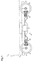
Fig. 3 is a plan view of the caliper device. -
Fig. 4A is a side view of a caliper device andFig. 4B is a side view of a caliper device disposed opposite to the caliper device ofFig. 4A . -
Fig. 5 is an exploded perspective view of a drive-side friction mechanism and components therearound in the caliper device. -
Fig. 6 is a sectional view of the drive-side friction mechanism and components therearound. -
Fig. 7 is an exploded perspective view of a brake-side friction mechanism and components therearound disposed closer to a first brake arm in the caliper device. -
Fig. 8 is a sectional view of the brake-side friction mechanism and components therearound. -
Figs. 9A-9D are schematic sectional views of the drive-side friction mechanism and components therearound illustrating assembling steps of the drive-side friction mechanism. -
Figs. 10A-10D are plan views illustrating an action of the caliper device. -
Fig. 11 is a sectional view of the drive-side friction mechanism and components therearound in the caliper device of Modification Example 7(A). -
Fig. 12 is a sectional view of the drive-side friction mechanism and components therearound in the caliper device of Modification Example 7(B). -
Fig. 13A is a plan view of an insertion portion of a second drive arm and components therearound in the caliper device of Modification Example 7(C) andFig. 13B is a sectional view of the insertion portion along theline 13B-13B inFig. 13A . -
Fig. 14 is a sectional view of the drive-side friction mechanism and components therearound in the caliper device of Modification Example 7(D). -
Fig. 15 is a sectional view of the drive-side friction mechanism and components therearound in the caliper device of Modification Example 7(E). -
Fig. 16 is a sectional view of the drive-side friction mechanism and components therearound in the caliper device of Modification Example 8(A). -
Fig. 17 is a sectional view of the drive-side friction mechanism and components therearound in the caliper device of Modification Example 8(B). -
Fig. 18 is a sectional view of the drive-side friction mechanism and components therearound in the caliper device of Modification Example 8(C). -
Fig. 19 is a sectional view of the drive-side friction mechanism and components therearound in the caliper device of Modification Example 8(D). -
Fig. 20 is a sectional view of the drive-side friction mechanism and components therearound in the caliper device of Modification Example 8(E). - One embodiment of a railway disc brake device will be now described with reference to the accompanying drawings.
- Referring to
Fig. 1 , adisc brake device 10 may be attached to atruck 3 that supports a chassis 2 of arailroad car 1. Thedisc brake device 10 is forced against adisc rotor 6 rotating together with an axle 5 that rotates a wheel 4 of thetruck 3. In this manner, a braking force is applied to the wheel 4. - The
disc brake device 10 may include anair ventilation unit 11 as a fluid system, and at least onecaliper device 20 that is fluidically coupled to theair ventilation unit 11. Theair ventilation unit 11 may be attached to, for example, thetruck 3 to provide compressed air to thecaliper device 20. Thecaliper device 20 presses thedisc rotor 6 attached to, for example, the axle 5 with the compressed air. A singleair ventilation unit 11 may be fluidically coupled to a plurality of thecaliper devices 20. When a braking force is applied to the wheel 4, theair ventilation unit 11 provides compressed air to the caliper device(s) 20. Whereas when the braking force that has been applied to the wheel 4 is canceled and no braking force is applied, theair ventilation unit 11 exhausts the compressed air from the caliper device(s) 20. Thedisc brake device 10 may operate the caliper device(s) 20 by providing a gas other than the compressed air or other fluid such as hydraulic fluid to the caliper device(s) 20, instead of the compressed air provided by theair ventilation unit 11. - Referring to
Fig. 2 , thecaliper device 20 may include amain body 30 attached to the truck 3 (seeFig. 1 ), and afirst brake arm 40 and asecond brake arm 50 that are provided swingably with respect to themain body 30. - The
main body 30 may include an bottom 31 A and anarm support portion 31. Thearm support portion 31 may include first andsecond arm portions portion 32 where is to be attached to thetruck 3 with four bolts (not shown) and that extends opposite to the first andsecond arm portions second arm portions - The
first brake arm 40 may be coupled to thefirst arm portion 31 B with anarm pivot shaft 21A that has a pivot axis CD1. Thearm pivot shaft 21A may be able to revolve relative to thefirst arm portion 31 B but not able to revolve relative to thefirst brake arm 40. - A pair of
arms 41 of thefirst brake arm 40 may be separated from each other in the axial direction of thearm pivot shaft 21A and extend such that thearms 41 face to each other. Aninsertion portion 42 through which thearm pivot shaft 21A is inserted may be formed in eacharm 41. Akey member 27A may be inserted between thearm pivot shaft 21A and one of theinsertion portions 42. In this manner, a relative rotation between thearm pivot shaft 21A and thefirst brake arm 40 may be inhibited. Awasher 28A that covers an end face of thearm pivot shaft 21 A in its axial direction and an end face of theinsertion portion 42 may be fixed to thearm pivot shaft 21A with abolt 29A. Thereby it is possible to prevent thekey member 27A from falling off between thearm pivot shaft 21A and theinsertion portion 42. - Each
arm 41 may include anoutput portion 43 that extends from theinsertion portion 42, and aninput portion 44 that extends from theinsertion portion 42 in a direction different from the output portion 43 (the opposite direction in the embodiment). At a tip of theoutput portion 43, atip coupling portion 45 that couples the pair ofarms 41 to each other may be formed. - A first
brake shoe mount 60 may be coupled at the tip portion of theoutput portion 43 with a brakeshoe pivot shaft 22A that has a pivot axis CB1 such that it moves swingably with respect to theoutput portion 43. The brakeshoe pivot shaft 22A may be inserted into a pair of supportingportions 62 of the firstbrake shoe mount 60 and thetip coupling portion 45 of thefirst brake arm 40. The brakeshoe pivot shaft 22A may be fixed to thetip coupling portion 45 with abolt 23A such that theshaft 22A is unrotatable with respect to thetip coupling portion 45 and theshaft 22A may be also supported by a pair of supportingportions 62 such that it is rotatable with respect to the supportingportions 62. - The
second brake arm 50 may be coupled to thesecond arm portion 31C with anarm pivot shaft 21 B that has a pivot axis CD2. Thearm pivot shaft 21 B may be able to revolve relative to thesecond arm portion 31C but not able to revolve relative to thesecond brake arm 50. - A pair of
arms 51 of thesecond brake arm 50 may have the same configuration as the pair ofarms 41 of thefirst brake arm 40, and components of thesecond brake arm 50 are designated by the like reference numerals of the corresponding components of thefirst brake arm 40 such that the digit "4" in the tens place is replaced by "5". - Like the
first brake arm 40 and thearm pivot shaft 21A, akey member 27B may be inserted between thearm pivot shaft 21 B and aninsertion portion 52 of thesecond brake arm 50. In this manner, a relative rotation between thearm pivot shaft 21 B and thesecond brake arm 50 may be inhibited. Awasher 28B may be fixed to the end portion of thearm pivot shaft 21 B in the axial direction with abolt 29B. Thereby it is possible to prevent thekey member 27B from falling off between thearm pivot shaft 21B and theinsertion portion 52. - A second
brake shoe mount 70 may be coupled at the tip portion of theoutput portion 53 with a brakeshoe pivot shaft 22B that has a pivot axis CB2 such that it moves swingably with respect to theoutput portion 53. The brakeshoe pivot shaft 22B may be inserted into a pair of supportingportions 72 of the secondbrake shoe mount 70 and thetip coupling portion 55 of thesecond brake arm 50. The brakeshoe pivot shaft 22B may be fixed to thetip coupling portion 55 with abolt 23B such that theshaft 22B is unrotatable with respect to thetip coupling portion 55 and theshaft 22A may be also supported by a pair of supportingportions 72 such that it is rotatable with respect to the supportingportions 72. - Referring to
Fig. 3 , thefirst brake arm 40 and thesecond brake arm 50 may be disposed at each side of thedisc rotor 6 in the thickness direction of thedisc rotor 6. The firstbrake shoe mount 60 and the secondbrake shoe mount 70 may be disposed to face thedisc rotor 6 respectively in the thickness direction of thedisc rotor 6.Brake shoes disc rotor 6 may be attached to thebrake shoe mount - A
driving mechanism 80 may be attached to the tip portions of theinput portions brake arms shafts shafts input portions driving mechanism 80. Accordingly thebrake arms driving mechanism 80. - The
driving mechanism 80 may impart a driving force to theinput portions Fig. 1 ) such that the tip portions of theinput portions 44, 54 (fixingshafts driving mechanism 80 may include a return spring (not shown) that imparts, to theinput portions brake shoe 61 from thedisc rotor 6. When theair ventilation unit 11 exhausts the air while thebrake shoes disc rotor 6, the force applied to theinput portion 44 by the return spring becomes larger than the force applied to theinput portion 44 by thedriving mechanism 80 based on the compressed air so that thebrake shoe 61 moves away from thedisc rotor 6. - Referring to
Fig. 4A , in themain body 30, a drive-side friction mechanism 90 may be provided on thesecond arm portion 31C of thesecond brake arm 50. However, referring toFig. 4B , the drive-side friction mechanism 90 is not provided on thefirst arm 31 B of thefirst brake arm 40 in themain body 30. The drive-side friction mechanism 90 shown inFig. 4A may restrict the swinging movement of thesecond brake arm 50 with respect to the main body 30 (thearm pivot shaft 21B) by applying friction force to thearm pivot shaft 21 B. The drive-side friction mechanism 90 may be disposed closer to theinput portion 54 with reference to thearm pivot shaft 21 B (on the drive mechanism side) and between the pair ofarms 51 in the axial direction of thearm pivot shaft 21 B. - Referring to
Fig. 4A , a brake-side friction mechanism 100 may be provided on one of the two supportingportions 72 of the secondbrake shoe mount 70. Referring toFig. 4B , another brake-side friction mechanism 100 may be provided on one of the two supportingportions 62 of the firstbrake shoe mount 60. - Referring again to
Fig. 4A , the brake-side friction mechanism 100 provided on the secondbrake shoe mount 70 may apply a friction force to the brakeshoe pivot shaft 22B to limit the swinging movement of the secondbrake shoe mount 70 with respect to the brakeshoe pivot shaft 22B (the output portion 53). In like wise manner, referring again toFig. 4B , the brake-side friction mechanism 100 provided on the firstbrake shoe mount 60 may apply a friction force to the brakeshoe pivot shaft 22A to limit the swinging movement of the firstbrake shoe mount 60 with respect to the brakeshoe pivot shaft 22A (the output portion 43). The brake-side friction mechanisms 100 may be disposed closer to theinsertion portions brake arms shoe pivot shafts Figs. 4A and 4B . More specifically, the brake-side friction mechanisms 100 may be disposed outside the pairs ofarms brake arms - Structure of the drive-
side friction mechanism 90 and components therearound, and structure of the brake-side friction mechanisms 100 and components therearound will be now described in detail with reference toFigs. 5-8 . Here, the structure of the brake-side friction mechanism 100 provided on the firstbrake shoe mount 60 is same as the brake-side friction mechanism 100 provided on the secondbrake shoe mount 70 so that the structure of the brake-side friction mechanism 100 provided on the firstbrake shoe mount 60 will be mainly described and the description of the brake-side friction mechanism 100 provided on the secondbrake shoe mount 70 will be omitted. - Referring to
Fig. 5 , the driving-side friction mechanism 90 may include aplug 91 that is attached to thesecond arm portion 31C of themain body 30. Afriction member 93 that has a friction surface, and at least one (for example, three) pressing member(s) 93 may be attached to theplug 91. Thefriction member 93 may have a bottomed cylindrical shape. The pressingmember 94 may be, for example, a disc spring and sandwiched between theplug 91 and thefriction member 93. The number of thepressing members 94 provided may be one, two, four or more. - On the
plug 91, acylindrical screw portion 91A, acolumnar sealing portion 91B and acolumnar attachment portion 91C may be sequentially formed. As shown inFig. 5 , the diameters of these portions sequentially decrease from thescrew portion 91 A, the sealingportion 91 B and theattachment portion 91C in the stated order. Moreover, afirst step portion 91D may be formed between the sealingportion 91 B and thescrew portion 91A, and asecond step portion 91 E may be formed between the sealingportion 91 B and theattachment portion 91C. A male thread (not shown inFig. 5 ) may be formed on the outer circumferential surface of thescrew portion 91A. Aseal 92 may be attached to the periphery of the sealingportion 91 B. Theseal 92 may be an O-ring. - Referring to
Fig. 6 , afirst housing portion 34 that houses thearm pivot shaft 21 B may be formed in thesecond arm portion 31C of themain body 30. Thefirst housing portion 34 may extend in the radial direction of the arm pivot shaft 21 B. At the center of thefirst housing portion 34 in the axial direction of thearm pivot shaft 21 B, asecond housing portion 35 that houses the drive-side friction mechanism 90 may be formed. Thesecond housing portion 35 may extend from thefirst housing portion 34 toward the driving mechanism with reference to thearm pivot shaft 21B (seeFig. 4A ). Thefirst housing portion 34 and thesecond housing portion 35 may each have an internal space that communicates with each other. - A portion of the
arm pivot shaft 21B housed in thefirst housing portion 34 may have a pair ofseals 25 at each end of the portion. Theseals 25 may be, for example, O-rings. An area of thearm pivot shaft 21 B between the pair ofseals 25 may be filled with grease which is one type of lubricant. - The
second housing portion 35 may include athread portion 35A on which a female thread is formed, and a sealingportion 35B that is configured to have an inner diameter smaller than that of thethread portion 35A. Astep portion 35C may be formed between thethread portion 35A and the sealingportion 35B. - When the drive-
side friction mechanism 90 is attached to thesecond arm portion 31C of themain body 30, theplug 91 plugs the opening of thesecond housing portion 35 when thescrew portion 91A is screwed to thethread portion 35A of thesecond housing portion 35. At this point, thefirst step portion 91 D contacts thestep portion 35C of thesecond housing portion 35. The sealingportion 91 B of theplug 91 may be inserted into the sealingportion 35B of thesecond housing portion 35 and the gap between the sealingportion 91 B and the sealingportion 35B is sealed with theseal 92. As for thefirst housing portion 34, the gap between thefirst housing portion 34 and thearm pivot shaft 21 B may be sealed with the pair ofseals 25 so that the internal spaces defined by the pair ofseals 25 and theseal 92 of theplug 91 are sealed in the first andsecond housing portions friction member 93 and the pressing member(s) 94 are disposed within the sealed internal spaces. Thefriction member 93 may be disposed closer to the arm pivot shaft with reference to the pressing member(s) 94. - The pressing member closest to the sealing
portion 91 B among the plurality of pressingmembers 94 may contact thesecond step portion 91 E, and the pressing member closest to thefriction member 93 among the plurality of pressingmembers 94 may contact the end face of acylindrical portion 93A of thefriction member 93. - Since the plurality of pressing
members 94 are sandwiched between theplug 91 and thefriction member 93 as shown inFig. 6 , the plurality of pressingmembers 94 are compressed. The plurality of pressingmembers 94 may push thefriction member 93 toward thearm pivot shaft 21B so that thefriction member 93 may be pressed against the arm pivot shaft 21 B. A friction force generated by sliding contact between the friction surface of thefriction member 93 and thearm pivot shaft 21 B may be referred to as an arm holding friction force. The position to fix thefriction member 93 and the magnitude of the arm holding friction force may be adjustable incrementally or non-incrementally depending on the number of thepressing members 94, the size and material of thepressing members 94, and/or the insertion depth of theplug 91 and the like. In the embodiment, thescrew portion 91A of theplug 91 and/or thepressing members 94 are one example of an adjustment means to adjust the position where thefriction member 93 is fixed. - Referring to
Fig. 7 , similarly to the drive-side friction mechanism 90, the brake-side friction mechanism 100 may include aplug 101, afriction member 103, and at least one (for example, three) pressing member(s) 104. Theplug 101, thefriction member 103, and the pressing member(s) 104 may have the same configuration as theplug 91, thefriction member 93, and the pressing member(s) 94 of the drive-side friction mechanism 90 respectively (seeFig. 5 ). The number of thepressing members 104 provided may be one, two, four or more. - Referring to
Fig. 8 , a pair ofseals 26 may be attached to portions of the brakeshoe pivot shaft 22A where are inserted into the pair of supportingportions 62 respectively. Between the pair ofseals 26 of the brakeshoe pivot shaft 22A and the portions of the supportingportion 62 corresponding to the pair ofseals 26, grease which is one type of lubricant may be provided. - A
housing portion 63 where the brake-side friction mechanism 100 is housed may be formed on the supportingportion 62. Thehousing portion 63 may include athread portion 63A on which a female thread is formed,and a sealingportion 63B that is configured to have an inner diameter smaller than that of thethread portion 63A. Astep portion 63C may be formed between thethread portion 63A and the sealingportion 63B. - Referring to
Fig. 8 , ascrew portion 101 A, a sealingportion 101 B and anattachment portion 101C may be sequentially formed on theplug 101. Theplug 101 plugs the opening of thehousing portion 63 when thescrew portion 101 A is screwed to thethread portion 63A of thehousing portion 63. At this point, afirst step portion 101 D contacts thestep portion 63C of thehousing portion 63. The sealingportion 101 B of theplug 101 may be inserted into the sealingportion 63B of thehousing portion 63 and the gap between the sealingportion 101 B and the sealingportion 63B is sealed with aseal 102 provided on the sealingportion 101B. The gap between the supportingportion 62 and the brakeshoe pivot shaft 22A may be sealed with the pair ofseals 26 so that the internal spaces defined by the pair ofseals 26 and theseal 102 of theplug 101 are sealed in thehousing portion 63 and the supportingportion 62. Thefriction member 103 and the pressing member(s) 104 are disposed within the sealed internal spaces. Thefriction member 103 may be disposed closer to the brakeshoe pivot shaft 22A with reference to the pressing member(s) 104. - Since the three
pressing members 104 are sandwiched between theplug 101 and thefriction member 103 as shown inFig. 8 , the threepressing members 104 are compressed therebetween. Thepressing members 104 may push thefriction member 103 toward the brakeshoe pivot shaft 22A so that thefriction member 103 may be pressed against the brakeshoe pivot shaft 22A. - How to attach the drive-
side friction mechanism 90 to themain body 30 will be now described with reference toFig. 9 . Since how to attach the brake-side friction mechanism 100 to the brake shoe mounts 60, 70 respectively is same as how to attach the drive-side friction mechanism 90 to themain body 30, the description of the former will be hereunder omitted. Note that thethread portion 35A of thesecond housing portion 35 is schematically illustrated inFig. 9 for the sake of simplicity. - Attachment of the drive-
side friction mechanism 90 to themain body 30 may be performed after themain body 30 has been attached to the second brake arm 50 (seeFig. 2 ) through thearm pivot shaft 21 B. The attachment process may include a friction member disposing step, a pressing member attaching step, and a plug attaching step. - Referring to
Fig. 9A , in the friction member disposing step, thefriction member 93 may be inserted into the sealingportion 35B of thesecond housing portion 35 in themain body 30. - Referring to
Fig. 9B , in the pressing member attaching step, the threepressing members 94 may be attached to theattachment portion 91C of theplug 91. At this point, a worker who performs the attachment process of the drive-side friction mechanism 90 to themain body 30 may check the number ofpressing members 94 attached to theplug 91. In the state where the threepressing members 94 have been attached to theattachment portion 91C, theattachment portion 91C may protrude out from the threepressing members 94. In this way, it is possible to prevent thepressing members 94 from falling out of theattachment portion 91C. - Finally in the plug attaching step, the
screw portion 91A of theplug 91 to which thepressing members 94 have been attached may be screwed to thethread portion 35A of thesecond housing portion 35 as shown inFig. 9C . In this manner, theplug 91 may be inserted in the direction indicated by the arrow inFig. 9C into thesecond housing portion 35. When thescrew portion 91 A is screwed into thethread portion 35A, the tip of theattachment portion 91C of theplug 91 is inserted into thecylindrical portion 93A of thefriction member 93 and the pressingmember 94 contacts thecylindrical portion 93A of thefriction member 93. In this way, thefriction member 93 moves toward thearm pivot shaft 21 B together with theplug 91. Thefriction member 93 contacts thearm pivot shaft 21B and any further movement of thefriction member 93 toward thearm pivot shaft 21 B is stopped but theplug 91 continues to move toward thearm pivot shaft 21 B so that the threepressing members 94 are compressed. When thefirst step portion 91 D of theplug 91 contacts thestep portion 35C of thesecond housing portion 35 as illustrated inFig. 9D , the worker stops screwing of theplug 91 into thesecond housing portion 35. Alternatively theplug 91 may be attached to thesecond housing portion 35 by press fitting, adhesive bonding or welding instead of screwing. As long as theplug 91 is adequately attached to thesecond housing portion 35, any attaching method may be adopted in addition to screwing. A method to attach theplug 101 to thehousing portion 63 is also not limited to screwing. - Operation of the
caliper device 20 will be described with reference toFig. 10 . In the following description, a swing direction of thebrake arms disc rotor 6 will be referred to as a "swing direction R1," whereas a swing direction of thebrake arms disc rotor 6 will be referred to as a "swing direction R2." In the illustrated example, thedriving mechanism 80 may include a movable structure, which may be a piston rod, and a fixed structure, which may be a cylinder. Thebrake arm 40 may be coupled to the movable structure of thedriving mechanism 80 and thebrake arm 50 may be coupled to the fixed structure of thedriving mechanism 80. The fixed structure (for example, the cylinder) of thedriving mechanism 80 may have a weight larger than that of the movable structure (for example, the piston rod) and have an inertia force larger than that of the movable structure. - Referring to
Fig. 10A , thedriving mechanism 80 drives thefirst brake arm 40 to swing in the swing direction R1 around the pivot axis CD1 of thearm pivot shaft 21A, and thedriving mechanism 80 moves in the direction indicated by the arrow Y1 inFig. 10A . Consequently thesecond brake arm 50 swings in the swing direction R1 around the pivot axis CD2 of the arm pivot shaft 21 B. As a result, the distance between the tip of theinput portion 44 and the tip of the input portion 54 (the distance between the fixingshaft 24A and the fixingshaft 24B) is increased. In this way the first and second brake shoe mounts 60, 70 move closer to the thedisc rotor 6, and thebrake shoes disc rotor 6. - When the driving of the
driving mechanism 80 is stopped and compressed air is exhausted from thedriving mechanism 80 as illustrated inFig. 10B , thefirst brake arm 40 swings in the swing direction R2 around the pivot axis CD1 of thearm pivot shaft 21A by the action of the return spring (not shown), and thedriving mechanism 80 returns to the position where thedriving mechanism 80 was situated before thefirst brake arm 40 was driven. Consequently, the firstbrake shoe mount 60 moves away from thedisc rotor 6 and thebrake shoe 61 moves away from thedisc rotor 6. On the other hand, thesecond brake arm 50 does not swing in the swing direction R2 around the pivot axis CD2 of thearm pivot shaft 21 B by the drive-side friction mechanism 90. Consequently thebrake shoe 71 of the secondbrake shoe mount 70 keeps contacting with thedisc rotor 6. - While the railroad car 1 (see
Fig. 1 ) travels, the wheel 4 and the truck 3 (seeFig. 1 ) move relative to each other in the axle direction (the thickness direction of the disc rotor 6), the vertical direction and the front-rear direction due to the vibration generated when therailroad car 1 travels. Especially when the wheel 4 and thetruck 3 move relatively in the axle direction, thebrake arms main body 30 attached to thetruck 3 move closer to and away from thedisc rotor 6 so that the brake shoe mounts 60, 70 move closer to and away from thedisc rotor 6. - For example, when the
disc rotor 6 moves in the direction indicated by the arrow Y2 as shown inFig. 10C due to the vibration generated while therailroad car 1 travels, thebrake shoe 71 of the secondbrake shoe mount 70 is pushed by thedisc rotor 6. Thesecond brake arm 50 swings in the swing direction R2 around the pivot axis CD2 of thearm pivot shaft 21 B due to the force which the secondbrake shoe mount 70 receives from thedisc rotor 6 through thebrake shoe 71. - Moreover, the
second brake arm 50 is restricted from swinging around the pivot axis CD2 of thearm pivot shaft 21 B because of the drive-side friction mechanism 90. Therefore even when the vibration is generated while therailroad car 1 travels, thesecond brake arm 50 is maintained in the state illustrated inFig. 10C . - For example, when the
disc rotor 6 moves in the direction indicated by the arrow Y3 as shown inFig. 10D due to the vibration generated while therailroad car 1 travels, and thendisc rotor 6 returns to the position ofFig. 10A , thebrake shoe 71 of the secondbrake shoe mount 70 moves away from thedisc rotor 6. At the same time, thebrake shoe 61 of the firstbrake shoe mount 60 moves closer to thedisc rotor 6 but does not contact thedisc rotor 6. In this manner, thebrake shoes disc rotor 6. - According to the embodiment, the following advantageous effects can be obtained.
- (1) In the
caliper device 20, the swinging movements of thebrake arms friction mechanism 90 and thereby it is possible to hold thebrake shoes brake arms brake shoes disc rotor 6 or the wheel 4 when braking is not performed. Thecaliper device 20 preferably includes the drive-side friction mechanism 90 and the brake-side friction mechanism 100. In addition to the restriction of the relative movement between thebrake arms side friction mechanism 100, the swinging movement of thesecond brake arm 50 is restricted by the friction force imparted by the drive-side friction mechanism 90. In this way it is possible to restrict the swinging movement of thesecond brake arm 50 around the pivot axis CD2 of thearm pivot shaft 21 B due to the vibration caused while therailroad car 1 travels, and it is also possible to restrict the swinging movement of the brake shoe mounts 60, 70 around the pivot axes CB1, CB2 of the brakeshoe pivot shafts brake shoes disc rotor 6 repeatedly due to the vibration caused while therailroad car 1 travels. Therefore the frequency of thebrake shoes disc rotor 6 can be reduced. - (2) In the
caliper device 20, the drive-side friction mechanism 90 is provided on thesecond brake arm 50 but not provided on thefirst brake arm 40. This means that the drive-side friction mechanism 90 does not impart the friction force to thefirst brake arm 40 and thearm pivot shaft 21A so that the swinging movement of thefirst brake arm 40 is not restricted. Because the drive-side friction mechanism 90 does not applies the friction force to thefirst brake arm 40, excessive limitation of the swinging movements of the first andsecond brake arms arm pivot shafts side friction mechanism 90 will be prevented. Therefore thebrake shoes brake shoes disc rotor 6 to the state where thebrake shoes disc rotor 6. - (3) In a reference example where the drive-
side friction mechanism 90 is disposed closer to the output section with reference to thearm pivot shaft 21 B, a sufficient distance between thedisc rotor 6 and thearm pivot shaft 21 B needs to be secured for a space where the drive-side friction mechanism 90 is disposed in order to avoid interference between the drive-side friction mechanism 90 and thedisc rotor 6. Consequently the size of the caliper device may be increased for the reference example.
In this respect, the drive-side friction mechanism 90 according to the embodiment is disposed closer to the input portion of thesecond brake arm 50 with reference to the arm pivot shaft 21 B. Therefore the distance between thedisc rotor 6 and thearm pivot shaft 21 B is not increased. Consequently it is possible to prevent the increase in the size of thecaliper device 20, - (4) The friction mechanism disclosed in the '183 Publication is supported by a supporting shaft attached to a pair of arms. This means that a component for supporting the friction mechanism is provided, which will be nothing to do with the function of the caliper device, and the number of components relating to the friction mechanism is increased.
In this respect, in thecaliper device 20 according to the embodiment, the drive-side friction mechanism 90 is supported by thesecond housing portion 35 formed in themain body 30, and the brake-side friction mechanism 100 is supported by the supportingportions side friction mechanism 90 and the brake-side friction mechanism 100 are not necessary. Consequently it is possible to prevent increase of the number of components relating to the drive-side friction mechanism 90 and the brake-side friction mechanism 100. - (5) The
friction member 93 of the drive-side friction mechanism 90 is pressed against the arm pivot shaft 21 B. Therefore, compared to the reference example where thefriction member 93 is pressed against themain body 30 and thesecond brake arm 50, themain body 30 and thesecond brake arm 50 do not necessarily have configurations where thefriction member 93 is pressed on. Accordingly, it is possible to prevent complication of the configurations of themain body 30 and thesecond brake arm 50. - (6) The
friction member 93 may be pressed against thearm pivot shaft 21 B by the pressingmembers 94. Therefore, the frequency of thefriction member 93 moving away from thearm pivot shaft 21 B is decreased and consequently it is possible to impart the friction force to thearm pivot shaft 21 B in the stable manner. Moreover, since thefriction member 103 of the brake-side friction mechanism 100 is also pressed against the brakeshoe pivot shafts pressing members 104, the advantageous effect same as the drive-side friction mechanism 90 can be obtained for the brake-side friction mechanism 100. - (7) When a foreign substance exists between the
friction member 93 and thearm pivot shaft 21B, the friction force generated with thefriction member 93 becomes unstable.
However, in the drive-side friction mechanism 90 according to the embodiment, thefriction member 93 is disposed in the sealed internal space within the first andsecond housing portions main body 30 so that it is possible to prevent foreign substances from entering between thefriction member 93 and thearm pivot shaft 21B. As a result, the friction force generated with thefriction member 93 can be stabilized. Moreover, in the brake-side friction mechanism 100, thefriction member 103 is also disposed in the sealed internal space within the supportingportions housing portions side friction mechanism 90 can be obtained. - (8) To attach the drive-
side friction mechanism 90, after the threepressing members 94 have been attached to theattachment portion 91C of theplug 91, theplug 91 is screwed into thesecond housing portion 35. Therefore a worker who performs the attachment can easily check the number of thepressing members 94, which was three in the above-described embodiment. Consequently it is possible to prevent the drive-side friction mechanism 90 in which an improper number of thepressing members 94 are provided from being attached to thesecond housing portion 35. Moreover, since the brake-side friction mechanism 100 is attached in the same manner as the drive-side friction mechanism 90, the same advantageous effect as the drive-side friction mechanism 90 can be obtained. - (9) The
plug 91 is disposed in thesecond housing portion 35 at the position where thefirst step portion 91 D of theplug 91 contacts thestep portion 35C of thesecond housing portion 35. Consequently a worker who performs the assembling does not have to perform adjustment of the position of theplug 91 relative to thesecond housing portion 35 and therefore it is possible to enhance the assembling efficiency of the drive-side friction mechanism 90. The relationship between theplug 101 of the brake-side friction mechanism 100 and thehousing portion 63 is same as the relationship between theplug 91 of the drive-side friction mechanism 90 and thesecond housing portion 35 so that the same advantageous effect as the drive-side friction mechanism 90 can be obtained for the brake-side friction mechanism 100. - (10) The brake-
side friction mechanism 100 is disposed closer to theinsertion portions brake arms side friction mechanisms 100 are disposed on the opposite side to the insertion portion with reference to the brakeshoe pivot shafts side friction mechanisms 100 according to the embodiment can be placed on the inner side of thecaliper device 20. Consequently it is possible to prevent the size increase of thecaliper device 20. - (11) The
friction members 103 of the brake-side friction mechanism 100 are pressed against the brakeshoe pivot shafts friction members 103 are pressed against the brake shoe mounts 60, 70 and/or thefirst brake arm 40, thefriction members 103 according to the embodiment do not necessarily have a configuration to be pressed so that complication of the configurations of the brake shoe mounts 60, 70 and/or thefirst brake arm 40 is prevented. - (12) The
driving mechanism 80 swings thefirst brake arm 40 around thearm pivot shaft 21A. Thesecond brake arm 50 swings around thearm pivot shaft 21B as thedriving mechanism 80 moves. The drive-side friction mechanism 90 is provided in thesecond brake arm 50. Since the drive-side friction mechanism 90 is not provided in thefirst brake arm 40 that swings easily compared to thesecond brake arm 50, thefirst brake arm 40 can smoothly swing. Therefore thebrake shoes brake shoes disc rotor 6 to the state where thebrake shoes disc rotor 6. - (13) The drive-
side friction mechanism 90 is disposed between the pair ofarms 51. Compared to a reference example where the drive-side friction mechanism 90 is disposed outside the pair ofarms 51, it is possible to reduce the size of thecaliper device 20. - (14) In the pressing member attaching step of the drive-
side friction mechanism 90 attachment process, theattachment portion 91C protrudes out from the threepressing members 94 when the threepressing members 94 are attached to theattachment portion 91C. Therefore the threepressing members 94 are readily supported by theattachment portion 91C, and consequently a worker who performs the plug attaching step does not have to hold the threepressing members 94 when theplug 91 is attached to thesecond housing portion 35. Accordingly, it is possible to improve the efficiency of the attachment process of the drive-side friction mechanism 90. The structure and attachment process of the brake-side friction mechanism 100 are same as the drive-side friction mechanism 90 so that the same advantageous effects as the drive-side friction mechanism 90 can be obtained for the brake-side friction mechanism 100. - (15) After the drive-
side friction mechanism 90 has been attached to thesecond housing portion 35, theattachment portion 91C is inserted into thecylindrical portion 93A of thefriction member 93. Therefore the threepressing members 94 can be adequately compressed by theplug 91 and thefriction member 93. The structure of the brake-side friction mechanism 100 is same as the drive-side friction mechanism 90 so that the same advantageous effects as the drive-side friction mechanism 90 can be obtained for the brake-side friction mechanism 100. - The above-described embodiment is a merely example of the caliper device according to the invention and the disc brake including the same and the description of the embodiment does not intend to limit the invention to the embodiment. As for the caliper device according to the invention and the disc brake including the same, various modifications which will be described below and combinations of two or more modifications which are not contradict to each other will be possible in addition to the above-described embodiment.
- In the above-described embodiment, the drive-
side friction mechanism 90 is disposed closer to the input portion with reference to theinsertion portion 52 of thesecond brake arm 50. However the position of the drive-side friction mechanism 90 is not limited to this. Alternatively the drive-side friction mechanism 90 may be disposed closer to the second brake shoe mount 70 (the disc rotor 6) with reference to theinsertion portion 52, closer to thefirst arm 31 B, or on the opposite side to thefirst arm 31 B. Alternatively the drive-side friction mechanism 90 may be disposed outside the pair ofarms 51 in the axial direction of thearm pivot shaft 21 B. - In the above-described embodiment, a single drive-
side friction mechanism 90 is provided in thesecond arm portion 31C of themain body 30. Alternatively more than one drive-side friction mechanism 90 may be provided in thesecond arm portion 31C. - In the above-described embodiment, the brake-
side friction mechanism 100 is provided at one of the pair of the supportingportions 62 and one of the pair of the supportingportions 72 respectively of the brake shoe mounts 60, 70. Alternatively the brake-side friction mechanism 100 may be provided at the other of the pair of the supportingportions 62 and the other of the pair of the supportingportions 72, or at the both of the pair of the supportingportions 62 and the both of the pair of the supportingportions 72. Alternatively the brake-side friction mechanism 100 may be disposed on thetip coupling portions - In the above-described embodiment, the brake-
side friction mechanism 100 is disposed closer to the insertion portion of thebrake arms shoe pivot shafts side friction mechanism 100 is not limited to this. For instance, the brake-side friction mechanism 100 may be disposed on the opposite side to the insertion portions of thebrake arms shoe pivot shafts side friction mechanism 100 may be disposed opposite to the brake shoe with reference to the brakeshoe pivot shafts side friction mechanism 100 may be disposed between the pair ofarms 41 and the pair ofarms 51 in the axial direction of the brakeshoe pivot shafts - In the above-described embodiment, a single brake-
side friction mechanism 100 is respectively provided in the brake shoe mounts 60, 70. Alternatively more than one brake-side friction mechanism 100 may be provided in the brake shoe mounts 60, 70 respectively. - Although the
pressing members friction members pressing members pressing members attachment portion plugs friction members friction members - In the above-embodiment, the magnitude of the friction force generated by the friction mechanism is always increased irrespective of the position of the brake shoe (in other words, a brake position and a non-brake position). In the drive-
side friction mechanism 90 and the brake-side friction mechanism 100 described in the embodiment, thefriction members pressing members friction members - The drive-
side friction mechanism 90 described in the above-embodiment is attached to thesecond arm portion 31C of themain body 30 to apply the friction force to the arm pivot shaft 21 B. However the position where the drive-side friction mechanism 90 is attached and the member to which the friction force is applied from the drive-side friction mechanism 90 are not limited to these. Alternatively, for example, the following features (A)-(E) are possible. Furthermore, the features (A)-(E) may be appropriately combined to each other. - (A) Referring to
Fig. 11 , the drive-side friction mechanism 90 that is a first drive-side friction mechanism may be attached to athird housing portion 36 that is formed in parallel to the longitudinal direction of thefirst housing portion 34 at the end portion of thefirst housing portion 34 in the axial direction of thearm pivot shaft 21 B, instead of the second housing portion 35 (seeFig. 6 ) of thesecond arm portion 31C of themain body 30. The configuration of the internal space of thethird housing portion 36 may be same as that of the second housing portion 35 (seeFig. 6 ). In this case, thefriction member 93 of the drive-side friction mechanism 90 is pressed against theinput portion 54 of thesecond brake arm 50.
Alternatively the drive-side friction mechanism 90 may be disposed on the opposite side (closer to the disc rotor 6 (seeFig. 3 )) to the input portion with reference to the arm pivot shaft 21 B. In this case, thefriction member 93 of the drive-side friction mechanism 90 is pressed against theoutput portion 53 of the second brake arm 50 (seeFig. 3 ). A friction force generated by sliding contact between the friction surface of thefriction member 93 and a portion of the brake arm 50 (for example, theinput portion 54 or the output portion 53) may be referred to as an arm holding friction force. - (B) Referring to
Fig. 12 , the drive-side friction mechanism 90 that is the second drive-side friction mechanism may be attached to a housing portion 110 formed at the end portion of thearm pivot shaft 21 B in the axial direction. The configuration of the internal space of the housing portion 110 may be same as that of the second housing portion 35 (seeFig. 6 ). At each side of the housing portion 110 in the axial direction in thearm pivot shaft 21B, aseal 111 may be provided. Theseals 111 may be, for example, O-rings. In this way, the internal space of the housing portion 110 may be sealed. Furthermore, thearm pivot shaft 21B may be unable to revolve relative to thesecond arm portion 31C (seeFig. 6 ) and able to revolve relative to theinsertion portion 52 of thesecond brake arm 50. Thefriction member 93 is pressed against theinsertion portion 52 of thesecond brake arm 50. - (C) Referring to
Fig. 13A , the drive-side friction mechanism 90 that is a second drive-side friction mechanism may be attached to ahousing portion 56 formed in theinsertion portion 52 of thesecond brake arm 50. Thehousing portion 56 may be disposed on the outer side of thecaliper device 20 with reference to thearm pivot shaft 21B. Referring toFig. 13B , theseals 111 may be provided on thearm pivot shaft 21 B. Theseals 111 may be disposed on each side of thefriction member 93 on thearm pivot shaft 21 B. The configuration of the internal space of thehousing portion 56 may be same as that of the second housing portion 35 (seeFig. 6 ). Furthermore, thearm pivot shaft 21 B may be unable to revolve relative to thesecond arm portion 31C (seeFig. 6 ) and able to revolve relative to theinsertion portion 52 of thesecond brake arm 50. Thefriction member 93 is pressed against thearm pivot shaft 21 B. - (D) Referring to
Fig. 14 , the drive-side friction mechanism 90 that is a third drive-side friction mechanism may be attached to ahousing portion 57 formed in theinput portion 54 of thesecond brake arm 50. Thehousing portion 57 may be formed such that it penetrates theinput portion 54 in the direction along the axial direction of thearm pivot shaft 21 B. The configuration of the internal space of thehousing portion 57 may be same as that of the second housing portion 35 (seeFig. 6 ). An opposingportion 37 that extends toward thehousing portion 57 may be formed in thesecond arm portion 31C. The opposingportion 37 may contact thehousing portion 57. Thefriction member 93 is pressed against the opposingportion 37 of thesecond arm portion 31C. Alternatively, thehousing portion 57 may be formed in the output portion 53 (seeFig. 2 ). In this case, the opposingportion 37 of themain device 30 extends toward theoutput portion 53 and contacts thehousing portion 57. - (E) Referring to
Fig. 15 , the drive-side friction mechanism 90 that is the third drive-side friction mechanism may be attached to ahousing portion 112 that is formed in an intermediate portion of of thearm pivot shaft 21 B in the axial direction (an axially center portion of of thearm pivot shaft 21 B inFig. 15 ). The configuration of the internal space of thehousing portion 112 may be same as that of the housing portion 110 (seeFig. 12 ). Thefriction member 93 is pressed against thesecond arm portion 31C of themain body 30. Thearm pivot shaft 21 B may be able to revolve relative to thesecond arm portion 31C of themain body 30 but not able to revolve relative to thesecond brake arm 50. - The brake-
side friction mechanism 100 described in the above-embodiment is attached to the brake shoe mounts 60, 70 to apply the friction force to the brakeshoe pivot shafts side friction mechanism 100 is attached and the member to which the friction force is applied from the brake-side friction mechanism 100 are not limited to these. Alternatively, for example, the following features (A)-(E) are possible. Furthermore, the features (A)-(E) may be appropriately combined to each other. - Here, the structure of the brake-
side friction mechanism 100 provided on the firstbrake shoe mount 60 is similar to the brake-side friction mechanism 100 provided on the secondbrake shoe mount 70 so that the brake-side friction mechanism 100 provided on the firstbrake shoe mount 60 will be mainly described and the description of the brake-side friction mechanism 100 provided on the secondbrake shoe mount 70 will be omitted. For the sake of simplicity, illustration of thebrake shoe mount 60 may be partially omitted in the drawings referred in the following description. - (A) Referring to
Fig. 16 , the brake-side friction mechanism 100 that is a first brake-side friction mechanism may be attached to ahousing portion 120 formed at the end portion of the brakeshoe pivot shaft 22A in the axial direction. The configuration of the internal space of thehousing portion 120 may be same as that of the housing portion 63 (seeFig. 8 ). In this case, thefriction member 103 of the brake-side friction mechanism 100 is pressed against the supportingportion 62 of the firstbrake shoe mount 60. - (B) Referring to
Fig. 17 , the brake-side friction mechanism 100 that is a second brake-side friction mechanism may be attached to ahousing portion 64 formed at the end portion of the brakeshoe pivot shaft 22A in the axial direction. Thehousing portion 64 contacts theoutput portion 43 of thefirst brake arm 40. Thehousing portion 64 may be formed in the direction along the axial direction of the brakeshoe pivot shaft 22A and the configuration of thehousing portion 64 may be same as the housing portion 63 (seeFig. 8 ). In this case, thefriction member 103 of the brake-side friction mechanism 100 is pressed against theoutput portion 43 of thefirst brake arm 40. - (C) Referring to
Fig. 18 , the brake-side friction mechanism 100 that is the second brake-side friction mechanism may be attached to ahousing portion 48 formed in theoutput portion 43 of thefirst brake arm 40. Thehousing portion 48 may be formed such that it penetrates theoutput portion 43 in the direction along the axial direction of the brakeshoe pivot shaft 22A and the configuration of thehousing portion 48 may be same as the housing portion 63 (seeFig. 8 ). An opposingportion 65 that extends toward theoutput portion 43 may be formed in the supportingportion 62. The opposingportion 65 contacts theoutput portion 43. In this case, thefriction member 103 of the brake-side friction mechanism 100 is pressed against the opposingportion 65. - (D) Referring to
Fig. 19 , the brake-side friction mechanism 100 that is a third brake-side friction mechanism may be attached to ahousing portion 49 formed in theoutput portion 43 of thefirst brake arm 40. The configuration of the internal space of thehousing portion 49 may be same as that of the housing portion 63 (seeFig. 8 ). In this case, the brakeshoe pivot shaft 22A may be unable to revolve relative to the supportingportion 62 and able to revolve relative to theoutput portion 43. In this case, thefriction member 103 of the brake-side friction mechanism 100 is pressed against the brakeshoe pivot shaft 22A. - (E) Referring to
Fig. 20 , the brake-side friction mechanism 100 that is a third brake-side friction mechanism may be attached to ahousing portion 121 formed at a portion of the brakeshoe pivot shaft 22A that faces theoutput portion 43. The configuration of thehousing portion 121 may be same as that of the housing portion 120 (seeFig. 16 ). In this case, the brakeshoe pivot shaft 22A may be unable to revolve relative to the supportingportion 62 and able to revolve relative to theoutput portion 43. Thefriction member 103 is pressed against theoutput portion 43. Alternatively thehousing portion 121 may be formed in a portion of thepivot shaft 22A that faces thetip coupling portion 45 of thefirst brake arm 40. In this case, thefriction member 103 is pressed against thetip coupling portion 45. - Instead of the drive-
side friction mechanism 90 and the brake-side friction mechanism 100 described in the above embodiment, the friction mechanism described in the'183 Publication may be provided on thesecond arm portion 31C of themain body 30 and the brake shoe mounts 60, 70. In this case, in theinput portion 54 of thesecond brake arm 50, a drive-side supporting shaft that supports the friction mechanism may be provided such that it extends in parallel with thearm pivot shaft 21B and couples the pair ofarms 51. Moreover, in theoutput portions brake arms shoe pivot shaft arms 41 and the pair ofarms 51 respectively. - The
pressing members side friction mechanism 90 and the brake-side friction mechanism 100 described in the above embodiment. In this case, theplugs friction members - In the above-described embodiment and Modification Examples 1-7 and 9, the drive-
side friction mechanism 90 may be provided on thefirst brake arm 40 instead of thesecond brake arm 50. - The brake-
side friction mechanism 100 may be omitted. - The
brake arm 40 generates a braking force by pressing thebrake shoe 61 against a rotor in order to retard the rotation of the rotor. The rotor may be thedisc rotor 6 or the wheel 4. The same applies to thebrake arm 50. - This disclosure further encompasses various embodiments described below.
- [Clause 1] In some implementations, the brake-side friction mechanism (100) is disposed closer to the insertion portion (42/52) with reference to the brake shoe pivot shaft (22A/22B).
- [Clause 2] In some implementations, the brake-side friction mechanism (100) includes a friction member (103) attached to one of the brake shoe mount (60/70) and the brake shoe pivot shaft (22A/22B) and pressed against other of the brake shoe mount and the brake shoe pivot shaft.
- [Clause 3] In some implementations, the brake-side friction mechanism (100) includes a friction member (103) attached to one of the brake shoe mount (60/70) and the output portion (45/53) and pressed against other of the brake shoe mount and the output portion.
- [Clause 4] In some implementations, the brake-side friction mechanism (100) includes a friction member (103) attached to one of the output portion (43/53) and the brake shoe pivot shaft (22A/22B) and pressed against other of the output portion and the brake shoe pivot shaft.
- [Clause 5] In some implementations, the brake-side friction mechanism (100) includes a friction member (103) that is pressed against the brake shoe pivot shaft (22A/22B).
- [Clause 6] In some implementations, the brake-side friction mechanism (100) further includes a pressing member (104) that presses the friction member (103) of the brake-side friction mechanism (100) against the brake shoe pivot shaft (22A/22B).
- [Clause 7] In some implementations, the friction member (103) of the brake-side friction mechanism (100) is supported and housed in a housing portion (63/73) formed in the brake shoe mount (60/70) or the brake arm (40/50), and the brake-side friction mechanism (100) further includes a plug (101) that plugs the housing portion (63/73).
- (Clause 8] In some implementations, the brake-side friction mechanism (100) further includes a pressing member (104) that presses the friction member (103) of the brake-side friction mechanism (100) against the brake shoe pivot shaft (22A/22B), and the plug (101) of the brake-side friction mechanism (100) has an attachment portion (101C) where the pressing member (104) of the brake-side friction mechanism (100) is attached.
- [Clause 9] In some implementations, the housing portion (63/73) of the brake-side friction mechanism (100) includes a step portion (63C) that contacts the plug (101) in a direction in which the plug (101) is inserted.
- It should be apparent to those skilled in the art that the present invention may be embodied in many other specific forms without departing from the scope of the invention. For example, some of the components may be omitted from the components described in the embodiments (or one or more aspects thereof). Further, components in different embodiments may be appropriately combined. The scope of the present invention and equivalence of the present invention are to be understood with reference to the appended claims.
Claims (18)
- A caliper device used together with a brake shoe to retard rotation of a rotor, comprising:a brake arm configured to be swung relative to a main body by a driving mechanism and move the brake shoe between a brake position and a non-brake position; anda friction mechanism arranged to increase friction against a swinging movement of the brake arm relative to the main body.
- The caliper device of claim 1, wherein the friction mechanism includes a friction member arranged to generate an arm holding friction force to impede the swinging movement of the brake arm relative to the main body.
- The caliper device of claim 2, wherein the friction mechanism is configured to adjust the magnitude of the arm holding friction force incrementally or non-incrementally.
- The caliper device of claim 2, further comprising:an adjustment means configured to adjust a position where the friction member is fixed in order to adjust the magnitude of the arm holding friction force.
- The caliper device of claim 2, further comprising:an arm pivot shaft coupling the brake arm swingably to the main body,wherein the friction member of the friction mechanism is arranged to sliding-contact one of the arm pivot shaft, the main body or the brake arm to generate the arm holding friction force.
- The caliper device of claim 2, wherein the brake shoe is one of first and second brake shoes that sandwich the rotor, the brake arm is one of first and second arms coupled to the first and second brake shoes respectively, and the friction mechanism is configured to increase only the friction against the swinging movement of the one of the first and second brake arms relative to the main body.
- The caliper device of claim 6, further comprising:the driving mechanism supported by the main body, the driving mechanism including a fixed structure and a movable structure,wherein the one of the first and second brake arms is coupled to the fixed structure of the driving mechanism, and other of the first and second brake arms is coupled to the movable structure of the driving mechanism.
- The caliper device of claim 1, wherein
the brake arm includes an insertion portion into which an arm pivot shaft supported by the main body is inserted, an input portion that extends from the insertion portion, and an output portion that extends from the insertion portion in a direction different from a direction in which the input portion extends,
the driving mechanism is coupled to input portion to impart a drive force to the input portion,
the output portion is coupled to a brake shoe mount through a brake shoe pivot shaft that has a pivot axis, the brake shoe is attached to the brake shoe mount,
the friction mechanism is a drive-side friction mechanism that applies a friction force to at least one selected from the group consisting of the input portion, the insertion portion, the output portion, the main body and the arm pivot shaft,
the caliper device further comprising:a brake-side friction mechanism different from the drive-side friction mechanism and configured to apply a friction force to at least one selected from the group consisting of the output portion, the brake shoe pivot shaft, and the brake shoe mount. - The caliper device of claim 5, wherein the friction mechanism is disposed closer to an input portion with reference to the arm pivot shaft.
- The caliper device of claim 5, wherein the friction member is attached to the main body and has a friction surface that is pressed against the brake arm or the arm pivot shaft.
- The caliper device of claim 5, wherein the friction member is attached to one of the brake arm and the arm pivot shaft and the friction member has a friction surface that is pressed against other of the brake arm and the arm pivot shaft.
- The caliper device of claim 5, wherein the friction member is attached to the brake arm or the arm pivot shaft, and has a friction surface that is pressed against the main body.
- The caliper device of claim 5, wherein the friction member has a friction surface that is pressed against the arm pivot shaft.
- The caliper device of claim 13, wherein the friction mechanism further includes a pressing member that presses the friction member against the arm pivot shaft.
- The caliper device of claim 14, whereinthe friction member and the pressing member are supported and housed in a housing portion formed in the main body or the brake arm, andthe friction mechanism further includes a plug that plugs the housing portion.
- The caliper device of claim 15, wherein the plug has an attachment portion where the pressing member is attached.
- The caliper device of claim 16, wherein the housing portion includes a step portion that contacts the plug in a direction in which the plug is inserted.
- A disc brake device comprising the caliper device according to any one of claims 1 to 17 configured to apply a braking force to the rotor when fluid is supplied from a fluid system.
Applications Claiming Priority (2)
| Application Number | Priority Date | Filing Date | Title |
|---|---|---|---|
| JP2015164989 | 2015-08-24 | ||
| JP2016154805A JP6803170B2 (en) | 2015-08-24 | 2016-08-05 | Caliper device and disc brake device with this device |
Publications (2)
| Publication Number | Publication Date |
|---|---|
| EP3135946A1 true EP3135946A1 (en) | 2017-03-01 |
| EP3135946B1 EP3135946B1 (en) | 2022-01-05 |
Family
ID=56787374
Family Applications (1)
| Application Number | Title | Priority Date | Filing Date |
|---|---|---|---|
| EP16185318.9A Active EP3135946B1 (en) | 2015-08-24 | 2016-08-23 | Caliper device and disc brake device including the same |
Country Status (2)
| Country | Link |
|---|---|
| US (1) | US11098775B2 (en) |
| EP (1) | EP3135946B1 (en) |
Families Citing this family (3)
| Publication number | Priority date | Publication date | Assignee | Title |
|---|---|---|---|---|
| JP6396721B2 (en) * | 2014-08-22 | 2018-09-26 | 曙ブレーキ工業株式会社 | Disc brake device and disc brake for railway |
| JP7444755B2 (en) * | 2020-10-28 | 2024-03-06 | ナブテスコ株式会社 | brake caliper device |
| CN115158390B (en) * | 2022-07-29 | 2024-03-01 | 中国铁道科学研究院集团有限公司 | Lightweight braking clamp unit |
Citations (3)
| Publication number | Priority date | Publication date | Assignee | Title |
|---|---|---|---|---|
| DE29613732U1 (en) * | 1995-09-07 | 1996-09-26 | Jenbacher Energiesysteme Ag | Disc brake, in particular for rail vehicles |
| EP1270980A1 (en) * | 2001-06-20 | 2003-01-02 | Sime-Stromag SA | Disc brake, in particular for industrial use |
| JP2010164183A (en) | 2009-01-19 | 2010-07-29 | Mitsubishi Heavy Ind Ltd | Disk brake device |
Family Cites Families (9)
| Publication number | Priority date | Publication date | Assignee | Title |
|---|---|---|---|---|
| IT1019374B (en) * | 1973-09-28 | 1977-11-10 | Knorr Bremse Gmbh | DISC BRAKE FOR RAILWAY VEHICLES |
| US4019608A (en) * | 1975-05-06 | 1977-04-26 | Norman Allen Johnson | Lever actuated caliper brake |
| FR2317158A1 (en) * | 1975-07-11 | 1977-02-04 | Lauzier Rene | IMPROVEMENT OF SHOE BRAKES FOR CYCLES AND SIMILAR |
| US4263990A (en) * | 1978-03-23 | 1981-04-28 | Yoshigai Kikai Kinzoku Kabushiki Kaisha | Caliper brake apparatus of the side-pull type |
| DE4407293C1 (en) | 1994-03-04 | 1995-10-05 | Knorr Bremse Systeme | Brake callipers for disc brakes of rail vehicle |
| US5547047A (en) * | 1995-01-25 | 1996-08-20 | New York Air Brake Corporation | Brake caliper shock and vibration isolation system |
| KR200288461Y1 (en) * | 2002-05-17 | 2002-09-10 | 민경한 | An oil pressure - cylinder |
| JP4939444B2 (en) | 2008-01-09 | 2012-05-23 | 曙ブレーキ工業株式会社 | Brake torque receiving mechanism with anti-vibration rubber for disc brake |
| US8151945B2 (en) * | 2010-05-25 | 2012-04-10 | Tektro Technology Corporation | Bicycle brake with a mechanism for quickly loosening brake cable |
-
2016
- 2016-08-23 EP EP16185318.9A patent/EP3135946B1/en active Active
- 2016-08-23 US US15/244,454 patent/US11098775B2/en active Active
Patent Citations (3)
| Publication number | Priority date | Publication date | Assignee | Title |
|---|---|---|---|---|
| DE29613732U1 (en) * | 1995-09-07 | 1996-09-26 | Jenbacher Energiesysteme Ag | Disc brake, in particular for rail vehicles |
| EP1270980A1 (en) * | 2001-06-20 | 2003-01-02 | Sime-Stromag SA | Disc brake, in particular for industrial use |
| JP2010164183A (en) | 2009-01-19 | 2010-07-29 | Mitsubishi Heavy Ind Ltd | Disk brake device |
Also Published As
| Publication number | Publication date |
|---|---|
| US20170058977A1 (en) | 2017-03-02 |
| US11098775B2 (en) | 2021-08-24 |
| EP3135946B1 (en) | 2022-01-05 |
Similar Documents
| Publication | Publication Date | Title |
|---|---|---|
| US8596394B2 (en) | Brake structure for wheel rotating device | |
| EP3135946B1 (en) | Caliper device and disc brake device including the same | |
| JP4396611B2 (en) | Suspension cylinder device for vehicle | |
| JP4816093B2 (en) | Friction transmission | |
| US8499903B2 (en) | Suspension device | |
| JP6803170B2 (en) | Caliper device and disc brake device with this device | |
| KR20210027177A (en) | Segmented spring for a ball screw | |
| CN104442783A (en) | Initiative brakeage regulating system with failure backup of motor drive liquid chamber | |
| TWI686318B (en) | Caliper device | |
| CN203460857U (en) | Driving braking force adjusting system with failure backup function for motor driving hydraulic cavity | |
| JP7233936B2 (en) | disc brake device | |
| JP2006193148A (en) | Corner part assembly for vehicle | |
| JP4708392B2 (en) | Electromagnetic shock absorber | |
| JP6269283B2 (en) | Vehicle differential | |
| JP2001526356A (en) | Drive | |
| JP5315067B2 (en) | Variable damping force damper | |
| JP2006342941A (en) | Mounting structure for driving force transmission device | |
| JP6641881B2 (en) | Vehicle brakes | |
| JP2008151168A (en) | Disk brake device | |
| JPH0266327A (en) | Fluid frictional clutch | |
| JP2016037980A (en) | Ball screw device | |
| JP2016098837A (en) | Brake device | |
| JP4798147B2 (en) | Brake structure | |
| JP2018501422A (en) | Hydraulic device with sleeve insert | |
| JP2011017395A (en) | Torque transmission device |
Legal Events
| Date | Code | Title | Description |
|---|---|---|---|
| PUAI | Public reference made under article 153(3) epc to a published international application that has entered the european phase |
Free format text: ORIGINAL CODE: 0009012 |
|
| STAA | Information on the status of an ep patent application or granted ep patent |
Free format text: STATUS: REQUEST FOR EXAMINATION WAS MADE |
|
| 17P | Request for examination filed |
Effective date: 20160823 |
|
| AK | Designated contracting states |
Kind code of ref document: A1 Designated state(s): AL AT BE BG CH CY CZ DE DK EE ES FI FR GB GR HR HU IE IS IT LI LT LU LV MC MK MT NL NO PL PT RO RS SE SI SK SM TR |
|
| AX | Request for extension of the european patent |
Extension state: BA ME |
|
| STAA | Information on the status of an ep patent application or granted ep patent |
Free format text: STATUS: EXAMINATION IS IN PROGRESS |
|
| 17Q | First examination report despatched |
Effective date: 20200828 |
|
| STAA | Information on the status of an ep patent application or granted ep patent |
Free format text: STATUS: EXAMINATION IS IN PROGRESS |
|
| GRAP | Despatch of communication of intention to grant a patent |
Free format text: ORIGINAL CODE: EPIDOSNIGR1 |
|
| STAA | Information on the status of an ep patent application or granted ep patent |
Free format text: STATUS: GRANT OF PATENT IS INTENDED |
|
| INTG | Intention to grant announced |
Effective date: 20210729 |
|
| GRAS | Grant fee paid |
Free format text: ORIGINAL CODE: EPIDOSNIGR3 |
|
| GRAA | (expected) grant |
Free format text: ORIGINAL CODE: 0009210 |
|
| STAA | Information on the status of an ep patent application or granted ep patent |
Free format text: STATUS: THE PATENT HAS BEEN GRANTED |
|
| AK | Designated contracting states |
Kind code of ref document: B1 Designated state(s): AL AT BE BG CH CY CZ DE DK EE ES FI FR GB GR HR HU IE IS IT LI LT LU LV MC MK MT NL NO PL PT RO RS SE SI SK SM TR |
|
| REG | Reference to a national code |
Ref country code: GB Ref legal event code: FG4D |
|
| REG | Reference to a national code |
Ref country code: CH Ref legal event code: EP |
|
| REG | Reference to a national code |
Ref country code: AT Ref legal event code: REF Ref document number: 1460854 Country of ref document: AT Kind code of ref document: T Effective date: 20220115 |
|
| REG | Reference to a national code |
Ref country code: DE Ref legal event code: R096 Ref document number: 602016068011 Country of ref document: DE |
|
| REG | Reference to a national code |
Ref country code: IE Ref legal event code: FG4D |
|
| REG | Reference to a national code |
Ref country code: LT Ref legal event code: MG9D |
|
| REG | Reference to a national code |
Ref country code: NL Ref legal event code: MP Effective date: 20220105 |
|
| REG | Reference to a national code |
Ref country code: AT Ref legal event code: MK05 Ref document number: 1460854 Country of ref document: AT Kind code of ref document: T Effective date: 20220105 |
|
| PG25 | Lapsed in a contracting state [announced via postgrant information from national office to epo] |
Ref country code: NL Free format text: LAPSE BECAUSE OF FAILURE TO SUBMIT A TRANSLATION OF THE DESCRIPTION OR TO PAY THE FEE WITHIN THE PRESCRIBED TIME-LIMIT Effective date: 20220105 |
|
| PG25 | Lapsed in a contracting state [announced via postgrant information from national office to epo] |
Ref country code: SE Free format text: LAPSE BECAUSE OF FAILURE TO SUBMIT A TRANSLATION OF THE DESCRIPTION OR TO PAY THE FEE WITHIN THE PRESCRIBED TIME-LIMIT Effective date: 20220105 Ref country code: RS Free format text: LAPSE BECAUSE OF FAILURE TO SUBMIT A TRANSLATION OF THE DESCRIPTION OR TO PAY THE FEE WITHIN THE PRESCRIBED TIME-LIMIT Effective date: 20220105 Ref country code: PT Free format text: LAPSE BECAUSE OF FAILURE TO SUBMIT A TRANSLATION OF THE DESCRIPTION OR TO PAY THE FEE WITHIN THE PRESCRIBED TIME-LIMIT Effective date: 20220505 Ref country code: NO Free format text: LAPSE BECAUSE OF FAILURE TO SUBMIT A TRANSLATION OF THE DESCRIPTION OR TO PAY THE FEE WITHIN THE PRESCRIBED TIME-LIMIT Effective date: 20220405 Ref country code: LT Free format text: LAPSE BECAUSE OF FAILURE TO SUBMIT A TRANSLATION OF THE DESCRIPTION OR TO PAY THE FEE WITHIN THE PRESCRIBED TIME-LIMIT Effective date: 20220105 Ref country code: HR Free format text: LAPSE BECAUSE OF FAILURE TO SUBMIT A TRANSLATION OF THE DESCRIPTION OR TO PAY THE FEE WITHIN THE PRESCRIBED TIME-LIMIT Effective date: 20220105 Ref country code: ES Free format text: LAPSE BECAUSE OF FAILURE TO SUBMIT A TRANSLATION OF THE DESCRIPTION OR TO PAY THE FEE WITHIN THE PRESCRIBED TIME-LIMIT Effective date: 20220105 Ref country code: BG Free format text: LAPSE BECAUSE OF FAILURE TO SUBMIT A TRANSLATION OF THE DESCRIPTION OR TO PAY THE FEE WITHIN THE PRESCRIBED TIME-LIMIT Effective date: 20220405 |
|
| PG25 | Lapsed in a contracting state [announced via postgrant information from national office to epo] |
Ref country code: PL Free format text: LAPSE BECAUSE OF FAILURE TO SUBMIT A TRANSLATION OF THE DESCRIPTION OR TO PAY THE FEE WITHIN THE PRESCRIBED TIME-LIMIT Effective date: 20220105 Ref country code: LV Free format text: LAPSE BECAUSE OF FAILURE TO SUBMIT A TRANSLATION OF THE DESCRIPTION OR TO PAY THE FEE WITHIN THE PRESCRIBED TIME-LIMIT Effective date: 20220105 Ref country code: GR Free format text: LAPSE BECAUSE OF FAILURE TO SUBMIT A TRANSLATION OF THE DESCRIPTION OR TO PAY THE FEE WITHIN THE PRESCRIBED TIME-LIMIT Effective date: 20220406 Ref country code: FI Free format text: LAPSE BECAUSE OF FAILURE TO SUBMIT A TRANSLATION OF THE DESCRIPTION OR TO PAY THE FEE WITHIN THE PRESCRIBED TIME-LIMIT Effective date: 20220105 Ref country code: AT Free format text: LAPSE BECAUSE OF FAILURE TO SUBMIT A TRANSLATION OF THE DESCRIPTION OR TO PAY THE FEE WITHIN THE PRESCRIBED TIME-LIMIT Effective date: 20220105 |
|
| PG25 | Lapsed in a contracting state [announced via postgrant information from national office to epo] |
Ref country code: IS Free format text: LAPSE BECAUSE OF FAILURE TO SUBMIT A TRANSLATION OF THE DESCRIPTION OR TO PAY THE FEE WITHIN THE PRESCRIBED TIME-LIMIT Effective date: 20220505 |
|
| REG | Reference to a national code |
Ref country code: DE Ref legal event code: R097 Ref document number: 602016068011 Country of ref document: DE |
|
| PG25 | Lapsed in a contracting state [announced via postgrant information from national office to epo] |
Ref country code: SM Free format text: LAPSE BECAUSE OF FAILURE TO SUBMIT A TRANSLATION OF THE DESCRIPTION OR TO PAY THE FEE WITHIN THE PRESCRIBED TIME-LIMIT Effective date: 20220105 Ref country code: SK Free format text: LAPSE BECAUSE OF FAILURE TO SUBMIT A TRANSLATION OF THE DESCRIPTION OR TO PAY THE FEE WITHIN THE PRESCRIBED TIME-LIMIT Effective date: 20220105 Ref country code: RO Free format text: LAPSE BECAUSE OF FAILURE TO SUBMIT A TRANSLATION OF THE DESCRIPTION OR TO PAY THE FEE WITHIN THE PRESCRIBED TIME-LIMIT Effective date: 20220105 Ref country code: EE Free format text: LAPSE BECAUSE OF FAILURE TO SUBMIT A TRANSLATION OF THE DESCRIPTION OR TO PAY THE FEE WITHIN THE PRESCRIBED TIME-LIMIT Effective date: 20220105 Ref country code: DK Free format text: LAPSE BECAUSE OF FAILURE TO SUBMIT A TRANSLATION OF THE DESCRIPTION OR TO PAY THE FEE WITHIN THE PRESCRIBED TIME-LIMIT Effective date: 20220105 Ref country code: CZ Free format text: LAPSE BECAUSE OF FAILURE TO SUBMIT A TRANSLATION OF THE DESCRIPTION OR TO PAY THE FEE WITHIN THE PRESCRIBED TIME-LIMIT Effective date: 20220105 |
|
| PGFP | Annual fee paid to national office [announced via postgrant information from national office to epo] |
Ref country code: GB Payment date: 20220822 Year of fee payment: 7 Ref country code: DE Payment date: 20220819 Year of fee payment: 7 |
|
| PLBE | No opposition filed within time limit |
Free format text: ORIGINAL CODE: 0009261 |
|
| STAA | Information on the status of an ep patent application or granted ep patent |
Free format text: STATUS: NO OPPOSITION FILED WITHIN TIME LIMIT |
|
| PG25 | Lapsed in a contracting state [announced via postgrant information from national office to epo] |
Ref country code: AL Free format text: LAPSE BECAUSE OF FAILURE TO SUBMIT A TRANSLATION OF THE DESCRIPTION OR TO PAY THE FEE WITHIN THE PRESCRIBED TIME-LIMIT Effective date: 20220105 |
|
| PGFP | Annual fee paid to national office [announced via postgrant information from national office to epo] |
Ref country code: FR Payment date: 20220823 Year of fee payment: 7 |
|
| 26N | No opposition filed |
Effective date: 20221006 |
|
| PG25 | Lapsed in a contracting state [announced via postgrant information from national office to epo] |
Ref country code: SI Free format text: LAPSE BECAUSE OF FAILURE TO SUBMIT A TRANSLATION OF THE DESCRIPTION OR TO PAY THE FEE WITHIN THE PRESCRIBED TIME-LIMIT Effective date: 20220105 |
|
| PG25 | Lapsed in a contracting state [announced via postgrant information from national office to epo] |
Ref country code: MC Free format text: LAPSE BECAUSE OF FAILURE TO SUBMIT A TRANSLATION OF THE DESCRIPTION OR TO PAY THE FEE WITHIN THE PRESCRIBED TIME-LIMIT Effective date: 20220105 |
|
| REG | Reference to a national code |
Ref country code: CH Ref legal event code: PL |
|
| PG25 | Lapsed in a contracting state [announced via postgrant information from national office to epo] |
Ref country code: LU Free format text: LAPSE BECAUSE OF NON-PAYMENT OF DUE FEES Effective date: 20220823 Ref country code: LI Free format text: LAPSE BECAUSE OF NON-PAYMENT OF DUE FEES Effective date: 20220831 Ref country code: CH Free format text: LAPSE BECAUSE OF NON-PAYMENT OF DUE FEES Effective date: 20220831 |
|
| REG | Reference to a national code |
Ref country code: BE Ref legal event code: MM Effective date: 20220831 |
|
| PG25 | Lapsed in a contracting state [announced via postgrant information from national office to epo] |
Ref country code: IT Free format text: LAPSE BECAUSE OF FAILURE TO SUBMIT A TRANSLATION OF THE DESCRIPTION OR TO PAY THE FEE WITHIN THE PRESCRIBED TIME-LIMIT Effective date: 20220105 Ref country code: IE Free format text: LAPSE BECAUSE OF NON-PAYMENT OF DUE FEES Effective date: 20220823 |
|
| PG25 | Lapsed in a contracting state [announced via postgrant information from national office to epo] |
Ref country code: BE Free format text: LAPSE BECAUSE OF NON-PAYMENT OF DUE FEES Effective date: 20220831 |
|
| PG25 | Lapsed in a contracting state [announced via postgrant information from national office to epo] |
Ref country code: HU Free format text: LAPSE BECAUSE OF FAILURE TO SUBMIT A TRANSLATION OF THE DESCRIPTION OR TO PAY THE FEE WITHIN THE PRESCRIBED TIME-LIMIT; INVALID AB INITIO Effective date: 20160823 |