EP3135906A1 - Vorrichtung mit eigenständiger stromerzeugung - Google Patents
Vorrichtung mit eigenständiger stromerzeugung Download PDFInfo
- Publication number
- EP3135906A1 EP3135906A1 EP15783571.1A EP15783571A EP3135906A1 EP 3135906 A1 EP3135906 A1 EP 3135906A1 EP 15783571 A EP15783571 A EP 15783571A EP 3135906 A1 EP3135906 A1 EP 3135906A1
- Authority
- EP
- European Patent Office
- Prior art keywords
- shaft
- power
- power generating
- driving shaft
- self
- Prior art date
- Legal status (The legal status is an assumption and is not a legal conclusion. Google has not performed a legal analysis and makes no representation as to the accuracy of the status listed.)
- Withdrawn
Links
Images


Classifications
-
- F—MECHANICAL ENGINEERING; LIGHTING; HEATING; WEAPONS; BLASTING
- F03—MACHINES OR ENGINES FOR LIQUIDS; WIND, SPRING, OR WEIGHT MOTORS; PRODUCING MECHANICAL POWER OR A REACTIVE PROPULSIVE THRUST, NOT OTHERWISE PROVIDED FOR
- F03G—SPRING, WEIGHT, INERTIA OR LIKE MOTORS; MECHANICAL-POWER PRODUCING DEVICES OR MECHANISMS, NOT OTHERWISE PROVIDED FOR OR USING ENERGY SOURCES NOT OTHERWISE PROVIDED FOR
- F03G5/00—Devices for producing mechanical power from muscle energy
- F03G5/06—Devices for producing mechanical power from muscle energy other than of endless-walk type
- F03G5/062—Devices for producing mechanical power from muscle energy other than of endless-walk type driven by humans
- F03G5/065—Devices for producing mechanical power from muscle energy other than of endless-walk type driven by humans operated by the hand
-
- F—MECHANICAL ENGINEERING; LIGHTING; HEATING; WEAPONS; BLASTING
- F03—MACHINES OR ENGINES FOR LIQUIDS; WIND, SPRING, OR WEIGHT MOTORS; PRODUCING MECHANICAL POWER OR A REACTIVE PROPULSIVE THRUST, NOT OTHERWISE PROVIDED FOR
- F03G—SPRING, WEIGHT, INERTIA OR LIKE MOTORS; MECHANICAL-POWER PRODUCING DEVICES OR MECHANISMS, NOT OTHERWISE PROVIDED FOR OR USING ENERGY SOURCES NOT OTHERWISE PROVIDED FOR
- F03G5/00—Devices for producing mechanical power from muscle energy
- F03G5/06—Devices for producing mechanical power from muscle energy other than of endless-walk type
-
- F—MECHANICAL ENGINEERING; LIGHTING; HEATING; WEAPONS; BLASTING
- F03—MACHINES OR ENGINES FOR LIQUIDS; WIND, SPRING, OR WEIGHT MOTORS; PRODUCING MECHANICAL POWER OR A REACTIVE PROPULSIVE THRUST, NOT OTHERWISE PROVIDED FOR
- F03G—SPRING, WEIGHT, INERTIA OR LIKE MOTORS; MECHANICAL-POWER PRODUCING DEVICES OR MECHANISMS, NOT OTHERWISE PROVIDED FOR OR USING ENERGY SOURCES NOT OTHERWISE PROVIDED FOR
- F03G5/00—Devices for producing mechanical power from muscle energy
- F03G5/086—Devices for producing mechanical power from muscle energy using flywheels
-
- F—MECHANICAL ENGINEERING; LIGHTING; HEATING; WEAPONS; BLASTING
- F03—MACHINES OR ENGINES FOR LIQUIDS; WIND, SPRING, OR WEIGHT MOTORS; PRODUCING MECHANICAL POWER OR A REACTIVE PROPULSIVE THRUST, NOT OTHERWISE PROVIDED FOR
- F03G—SPRING, WEIGHT, INERTIA OR LIKE MOTORS; MECHANICAL-POWER PRODUCING DEVICES OR MECHANISMS, NOT OTHERWISE PROVIDED FOR OR USING ENERGY SOURCES NOT OTHERWISE PROVIDED FOR
- F03G5/00—Devices for producing mechanical power from muscle energy
- F03G5/095—Devices for producing mechanical power from muscle energy with potential energy storage
-
- F—MECHANICAL ENGINEERING; LIGHTING; HEATING; WEAPONS; BLASTING
- F16—ENGINEERING ELEMENTS AND UNITS; GENERAL MEASURES FOR PRODUCING AND MAINTAINING EFFECTIVE FUNCTIONING OF MACHINES OR INSTALLATIONS; THERMAL INSULATION IN GENERAL
- F16H—GEARING
- F16H19/00—Gearings comprising essentially only toothed gears or friction members and not capable of conveying indefinitely-continuing rotary motion
- F16H19/02—Gearings comprising essentially only toothed gears or friction members and not capable of conveying indefinitely-continuing rotary motion for interconverting rotary or oscillating motion and reciprocating motion
- F16H19/06—Gearings comprising essentially only toothed gears or friction members and not capable of conveying indefinitely-continuing rotary motion for interconverting rotary or oscillating motion and reciprocating motion comprising flexible members, e.g. an endless flexible member
-
- F—MECHANICAL ENGINEERING; LIGHTING; HEATING; WEAPONS; BLASTING
- F16—ENGINEERING ELEMENTS AND UNITS; GENERAL MEASURES FOR PRODUCING AND MAINTAINING EFFECTIVE FUNCTIONING OF MACHINES OR INSTALLATIONS; THERMAL INSULATION IN GENERAL
- F16H—GEARING
- F16H31/00—Other gearings with freewheeling members or other intermittently driving members
- F16H31/001—Mechanisms with freewheeling members
-
- F—MECHANICAL ENGINEERING; LIGHTING; HEATING; WEAPONS; BLASTING
- F16—ENGINEERING ELEMENTS AND UNITS; GENERAL MEASURES FOR PRODUCING AND MAINTAINING EFFECTIVE FUNCTIONING OF MACHINES OR INSTALLATIONS; THERMAL INSULATION IN GENERAL
- F16H—GEARING
- F16H37/00—Combinations of mechanical gearings, not provided for in groups F16H1/00 - F16H35/00
- F16H37/02—Combinations of mechanical gearings, not provided for in groups F16H1/00 - F16H35/00 comprising essentially only toothed or friction gearings
-
- H—ELECTRICITY
- H02—GENERATION; CONVERSION OR DISTRIBUTION OF ELECTRIC POWER
- H02K—DYNAMO-ELECTRIC MACHINES
- H02K7/00—Arrangements for handling mechanical energy structurally associated with dynamo-electric machines, e.g. structural association with mechanical driving motors or auxiliary dynamo-electric machines
-
- F—MECHANICAL ENGINEERING; LIGHTING; HEATING; WEAPONS; BLASTING
- F05—INDEXING SCHEMES RELATING TO ENGINES OR PUMPS IN VARIOUS SUBCLASSES OF CLASSES F01-F04
- F05B—INDEXING SCHEME RELATING TO WIND, SPRING, WEIGHT, INERTIA OR LIKE MOTORS, TO MACHINES OR ENGINES FOR LIQUIDS COVERED BY SUBCLASSES F03B, F03D AND F03G
- F05B2260/00—Function
- F05B2260/40—Transmission of power
- F05B2260/403—Transmission of power through the shape of the drive components
Definitions
- the present invention relates to a self-power generating apparatus, and more particularly to a self-power generating apparatus capable of generating power by converting external forces alternately applied in forward and reverse directions into a one-direction force, and capable of generating power as a user winds a wire around a pulley coupled to a driving shaft and applies an external force to the wire with both hands of the user to rotate the pulley in a forward or reverse direction, thereby enhancing power generation efficiency.
- the battery since the battery has a limitation in use time, if power is fully discharged from the battery, the battery must be charged with power for the re-use thereof. However, when a user is moving or is outdoors, the battery may not be charged with power.
- the self-power generating apparatus according to the related art is configured with portability, power generation efficiency is weak, so that power is generated in small amount. Accordingly, the self-power generating apparatus according to the related art has a difficulty in generating power in amount required by the user.
- an object of the present invention is to provide a self-power generating apparatus capable of generating power by converting external forces alternately applied in forward and reverse directions into a one-direction force, and of generating power as a user winds a wire around a pulley shaft-coupled to a driving shaft and applies an external force to the wire with both hands of the user to rotate the pulley in a forward or reverse direction, thereby enhancing power generation efficiency.
- a self-power generating apparatus including a driving shaft alternately rotated in a forward direction or a reverse direction by an external force, a forward power transmission unit to transmit only a forward rotational force of the driving shaft to a power generating shaft, a reverse power transmission unit to transmit only a reverse rotation force of the driving shaft to the power generating shaft, and a power generator to generate power using a one-direction rotational force of the power generating shaft.
- a pulley may be coupled to the driving shaft, and the driving shaft may be alternately rotated in the forward direction or the reverse direction as a wire wound around the pulley of the driving shaft alternately reciprocates.
- the pulley may be coupled to a center of the driving shaft.
- the self-power generating apparatus may further include a cooperation shaft that is mounted perpendicularly to the driving shaft, has one end coupled to a first bevel gear, and is coupled to a pulley.
- a second bevel gear engaged with the first bevel gear may be coupled to one end of the driving shaft, and the cooperation shaft may be alternately rotated in the forward direction or the reverse direction as a wire wound around the pulley of the cooperation shaft alternately reciprocates, such that the driving shaft is alternately rotated in the forward direction or the reverse direction.
- one or both of the forward power transmission unit and the reverse power transmission unit may include a clutch driving part to transmit only one-direction power of the driving shaft, and a driven part to transmit power of the clutch driving part to the power generating shaft.
- the clutch driving part may include a first disc-shaped body, into which one of the driving shaft and the power generating shaft is inserted, such that the first disc-shaped body is rotatable relatively to the inserted shaft, a first spur gear formed on an outer circumferential surface of the first disc-shaped body, a first circular step difference groove coaxially formed in one surface of the first disc-shaped body, a first latch gear formed in one direction on an inner circumferential surface of the first circular step difference groove to transmit only one-direction rotation movement, and a first latch coupled to the shaft inserted into the first disc-shaped body to be engaged with the first latch gear.
- the driven part may include a second spur gear coupled to a remaining one of the driving shaft and the power generating shaft and engaged with the first spur gear, the first latch gear and the first latch may be formed to transmit a driving force only in the forward direction when applied to the forward power transmission unit, and the first latch gear and the first latch may be formed to transmit the driving force only in the reverse direction when applied to the reverse power transmission unit.
- one or both of the forward power transmission unit and the reverse power transmission unit may include a clutch driving part to transmit only one-direction power of the driving shaft, and a driven part to transmit power of the clutch driving part to the power generating shaft through a belt.
- the clutch driving part may include a third disc-shaped body, into which one of the driving shaft and the power generating shaft is inserted, such that the third disc-shaped body is rotatable relatively to the inserted shaft, a third circular step difference groove coaxially formed in one surface of the third disc-shaped body, a third latch gear formed on an inner circumferential surface of the third circular step difference groove, and a third latch coupled to the shaft inserted into the third disc-shaped body to be engaged with the third latch gear.
- the driven part may include a fourth disc-shaped body coupled to a remaining one of the driving shaft and the power generating shaft and linked with the third disc-shaped body through the belt.
- the third latch gear and the third latch may be formed to transmit a driving force only in the forward direction when applied to the forward power transmission unit, and the third latch gear and the third latch may be formed to transmit the driving force only in the reverse direction when applied to the reverse power transmission unit.
- the self-power generating apparatus may further include at least one flywheel coupled to the power generating shaft.
- the self-power generating apparatus may further include a rechargeable battery to store electrical energy generated from the power generator.
- the self-power generating apparatus may further include a housing that rotatably supports both ends of the driving shaft and both ends of the power generating shaft and has the power generator therein.
- a pulley may be coupled to the driving shaft, and the driving shaft and the power generating shaft may be arranged in parallel to each other.
- the power can be generated by converting the external force, which is alternately applied in the forward and reverse directions, into a one-direction force.
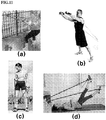
- a user winds the wire around the pulley coupled to the driving shaft and applies the external force to the wire with both hands to rotate the pulley in the forward and reverse directions so that the power can be generated. Accordingly, the power can be efficiently generated. Therefore, the self-power generation can be achieved together with various types of workouts.
- the flywheel is provided, so that the power generation efficiency can be more enhanced.
- the rechargeable battery is provided to store the electrical energy generated from the power generator, so that the user can use the electrical energy if necessary.
- the apparatus can generate power without the excessive vibration when the user applies the external force.
- the power can generated in the state that the apparatus is mounted on a fixed position, such as a tree, using the tow ring provided at one point of the housing.
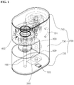
- FIG. 1 is a perspective view showing a self-power generating apparatus according to one embodiment of the present invention.
- FIG. 2 is a perspective view showing an inner part of the self-power generating apparatus according to one embodiment of the present invention.
- FIG. 3 is an exploded perspective view showing the self-power generating apparatus according to one embodiment of the present invention.
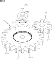
- FIG. 4 is an enlarged perspective view showing a rotation unit of a reverse power transmission unit of the self-power generating apparatus according to one embodiment of the present invention.
- FIG. 5 is an enlarged perspective view showing a rotation unit of a forward power transmission unit of the self-power generating apparatus according to one embodiment of the present invention.
- the self-power generating apparatus includes a driving shaft 100, a power generating shaft 200, a power generator 300, a power transmission unit 400, a rechargeable battery 600, and a housing 700 as shown in FIGS. 1 to 5 .
- the driving shaft 100 is a shaft that transmits a driving force to the power generating shaft 200 to generate electricity, and is alternately rotated in a forward or reverse direction by an external force applied thereto by a user
- a pulley P is fixedly shaft-coupled to the center of the driving shaft 100, and a wire W is wound around the pulley P.
- the user pulls both ends of the wire W to keep the wire W tightening.
- the user pulls one end of the wire W to rotate the pulley P in the forward direction, and then pulls the other end of the wire W to rotate the pulley P in the reverse direction.
- the driving shaft 100 is alternately rotated in the forward or reverse direction.
- a groove of the pulley P making contact with the wire W may be subject to surface treatment through sandblast or may be formed therein with protrusions to increase a frictional force.
- the power generating shaft 200 is a shaft that is rotated only in one direction by receiving an alternating rotational force of the driving shaft 100 through the power transmission unit 400.
- the driving shaft 100 and the power generating shaft 200 are arranged in parallel to each other, and the power transmission unit 400 converts the alternating rotational force of the driving shaft 100 into a one-direction rotational force to be transmitted to the power generating shaft 200.
- the power transmission unit 400 will be described later.
- the power generator 300 is provided to generate power using the one-direction rotational force of the power generating shaft 200.
- the power generator 300 may include a gearbox generator. To this end, a geared motor may be provided to be reversely operated.
- the shaft of the geared motor is rotated by the one-direction rotational force of the power generating shaft 200 to generate electricity.
- the geared motor includes a reduction gear
- the geared motor may rotate the power generating shaft 200 more rapidly than the force of the user, so that power can be generated.
- the geared motor may generate electricity using the one-direction rotational force of the power generating shaft 200.
- the rechargeable battery 600 may be provided to store electrical energy generated from the power generator 300.
- the rechargeable battery 600 may store the electrical energy generated from the power generator 300 and supply the electrical energy at the time point at which a user needs the electrical energy.
- the rechargeable battery 600 may include a secondary cell.
- the power transmission unit 400 converts the alternating rotational force of the driving shaft 100 into the one-direction rotational force to be transmitted to the power generating shaft 200, and includes a forward power transmission unit 410 and a reverse power transmission unit 420.
- the forward power transmission unit 410 transmits only forward rotational force of the driving shaft 100 to the power generating shaft 200
- the reverse power transmission unit 420 transmits only reverse rotational force of the driving shaft 100 to the power generating shaft 200.
- the forward power transmission unit 410 includes a clutch driving part A1 to transmit only forward power of the driving shaft 100 and a driven part A3 to transmit the power of the clutch driving part A1 to the power generating shaft 200.
- the clutch driving part A1 includes a first disc-shaped body A1-1 into which the driving shaft 100 is inserted so that the first disc-shaped body A1-1 is rotatable relatively to the driving shaft 100, a first spur gear A1-2 formed on the outer circumferential surface of the first disc-shaped body A1-1, a first circular step difference groove A1-3 coaxially formed in one surface of the first disc-shaped body A1-1, a first latch gear A1-4 formed in one direction on an inner circumferential surface of the first circular step difference groove A1-3 to transmit only forward rotation movement, and a first latch A1-5 engaged with the first latch gear A1-4 and coupled to the shaft inserted into the first disc-shaped body A1-1.
- the driven part A3 includes a second spur gear A3-1 shaft-coupled to the power generating shaft 200 and engaged with the first spur gear A1-2.
- the first latch A1-5 becomes engaged with the first latch gear A1-4, so that the first spur gear A1-2 of the first disc-shaped body A1-1 is rotated in the forward direction, and a second disc-shaped body A3-1 is rotated in the reverse direction by the second spur gear A3-1 engaged with the first spur gear A1-2, so that the power generating shaft 200 is rotated in the reverse direction.
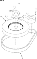
- the reverse power transmission unit 420 includes a clutch driving part B2 to transmit only reverse power of the driving shaft 100 and a driven part B4 to transmit the power of the clutch driving part B2 to the power generating shaft 200 through a belt bt.
- the clutch driving part B2 includes a third disc-shaped body B2-1 into which the driving shaft 100 is inserted so that the third disc-shaped body B2-1 is rotatable relatively to the driving shaft 100, a third circular step difference groove B2-2 coaxially formed in one surface of the third disc-shaped body B2-1, a third latch gear B2-3 formed in one direction on an inner circumferential surface of the third circular step difference groove B2-2 to transmit only reverse rotation movement, and a third latch B2-4 coupled to the shaft inserted into the third disc-shaped body B2-1 so that the third latch B2-4 is engaged with the third latch gear B2-3.
- the driven part B4 includes a fourth disc-shaped body B4-1 coupled to the power generating shaft 200 and linked with the third disc-shaped body B2-1 through the belt bt.
- the third latch B2-4 becomes engaged with the third latch gear B2-3, so that the third disc-shaped body B2-1 is rotated in the reverse direction. Therefore, the belt bt is rotated in the reverse direction. As the belt bt is rotated in the reverse direction, the fourth disc-shaped body B4-1 is rotated in the reverse direction.
- the power generating shaft 200 is rotated in the reverse direction by the forward power transmission unit 410.
- the power generating shaft 200 is rotated in the reverse direction by the reverse power transmission unit 420. In this case, the power generating shaft 200 is continuously rotated in one direction (reverse direction).
- the forward power transmission unit 410 and the reverse power transmission unit 420 include a one-way clutch or a one-way bearing that transmits power only in one direction, and do not transmit the power in an opposite direction.
- the forward power transmission unit 410 transmits power by the first spur gear A1-2 and the second spur gear A3-1
- the reverse power transmission unit 420 transmits power through the belt bt as configured above for the illustrative purpose
- various one-way clutches or various one-way bearings are applicable for the forward power transmission unit 410 and the reverse power transmission unit 420.
- the first latch gear A1-4 and the first latch A1-5 are formed to transmit only the forward rotation force of the driving shaft 100 to the power generating shaft 200, the first latch gear A1-4 and the first latch A1-5 are applicable for the forward power transmission unit 410. If the first latch gear A1-4 and the first latch A1-5 are formed to transmit only the reverse rotation force of the driving shaft 100 to the power generating shaft 200, the first latch gear A1-4 and the first latch A1-5 are applicable for the reverse power transmission unit 420. To this end, various types of one-way clutches or one-way bearings are applicable.
- At least one flywheel f may be coupled to the power generating shaft 200.
- the flywheel f may more effectively generate power by an inertia force.
- the housing 700 rotatably supports both ends of the driving shaft 100 and both ends of the power generating shaft 200, and is provided therein with the driving shaft 100, the power generating shaft 200, the power transmission unit 400, the power generator 300, and the rechargeable battery 600.
- the housing 700 rotatably supports both ends of the driving shaft 100 and both ends of the power generating shaft 200 and is provided therein with the power generator 300.
- the pulley P is exposed to the outside of the housing 700 so that the wire W is wound around the pulley P.
- the housing 700 includes upper and lower plates 710 and 720 mounted in parallel to each other in order to rotatably support both ends of the driving shaft 100 and both ends of the power generating shaft 200, and a main body 730 which connects the upper plate 710 with the lower plate 720 to close housing, and has an exposed part 730a formed at the center of one side thereof to expose the pulley P to the outside.
- the upper and lower plates 710 and 720 are mounted on both ends of the main body 730 in parallel to each other in order to rotatably support both ends of the driving shaft 100 and both ends of the power generating shaft 200.
- the main body 730 connects the upper plate 710 with the lower plate 720 to close the housing and to form a space in which the driving shaft 100, the power generating shaft 200, the power transmission unit 400, the power generator 300, and the rechargeable battery 600 are received.
- the user may wind the wire W around the pulley P exposed to the outside to generate power.
- the exposed part 730a is formed in a groove shape at one side of the main body 730 so that the pulley P fixedly coupled to the driving shaft 100 may be exposed, and a tow ring 701 is provided at one point of the main body 730.
- bearings br may be assembled with holes 730h formed in top and bottom surfaces of the exposed part 730a of the main body 730 to rotatably support the driving shaft 100.
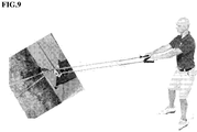
- the self-power generating apparatus is fixedly hanged on a fixed article, such as a tree, using the tow ring 701 provided at one point of the main body 730 of the housing 700.
- the tow ring 701 is hanged in the state a string is wound around the tree as shown in FIG. 9 .
- the driving shaft 100 is rotated in the reverse direction.
- the reverse power transmission unit 420 of the power transmission unit 400 transmits only the reverse rotational force to the power generating shaft 200.
- FIG. 6 is a perspective view showing a self-power generating apparatus according to another embodiment of the present invention.
- FIG. 7 is a perspective view showing an inner part of the self-power generating apparatus according to another embodiment of the present invention.
- FIG. 8 is a plan view showing the inner part of the self-power generating apparatus according to another embodiment of the present invention.
- FIGS. 6 to 8 a self-power generating apparatus according to another embodiment of the present invention will be described with reference to FIGS. 6 to 8 .
- the self-power generating apparatus includes a driving shaft 100, a power generating shaft 200, a power generator 300, a power transmission unit 400, a cooperation shaft 500, a rechargeable battery 600, and a housing 700.
- the power generating shaft 200, the power generator 300, the power transmission unit 400, and the rechargeable battery 600 have configurations the same as or similar to those of the previous embodiment, the details thereof will be omitted. The following description will be made while focusing on the cooperation relationship between the driving shaft 100 and the cooperation shaft 500 and the housing 700.
- a second bevel gear bg2 engaged with the first bevel gear bg1 is coupled to one end of the driving shaft 100.
- the cooperation shaft 500 is alternately rotated in forward and reverse directions, so that the driving shaft 100 may be alternately rotated in the forward and reverse directions.
- the alternating rotational force of the driving shaft 100 in the forward and reverse directions is converted into a one-direction rotational force to be transmitted to the power generating shaft 200 through the power transmission unit 400.
- Electricity may be generated from the power generator 300 by the one-direction rotational force of the power generating shaft 200.
- the electricity generated from the power generator 300 may be stored in the rechargeable battery 600.
- the housing 700' rotatably supports both ends of the driving shaft 100, both ends of the power generating shaft 200, and both ends of the cooperation shaft 500, and is provided therein with the power transmission unit 400, the power generator 300, and the rechargeable battery 600.
- the pulley P is exposed from the housing 700' so that the wire W may be wound around the pulley P.
- the housing 700' includes a base body 710' provided therein with the power transmission unit 400, the power generator 300, and the rechargeable battery 600 and having a substantially clockwise direction-half turned "L" shape, an axillary body 720' extending from one side of a top surface of the base body 710' to receive one end of the driving shaft 100 and one end of the cooperation shaft 500, and a support flange 730' extending from the opposite side of the top surface of the base body 710' to rotatably support the opposite end of the cooperation shaft 500.
- the cooperation shaft 500 is rotated in the forward direction, so that the driving shaft 100 is rotated in the forward direction.
- the forward power transmission unit 410 of the power transmission unit 400 transmits only the forward rotational force to the power generating shaft 200.
- the cooperation shaft 500 is rotated in the reverse direction, so that the driving shaft 100 is rotated in the reverse direction.
- the reverse power transmission unit 420 of the power transmission unit 400 transmits only the reverse rotational force to the power generating shaft 200.
- the power generating shaft 200 may be continuously rotated in the reverse direction, and power may be generated by the one-direction rotational force of the power generating shaft 200.
- the self-power generating apparatus is applicable for various types of workouts to generate power while allowing the user to work out.
Landscapes
- Engineering & Computer Science (AREA)
- General Engineering & Computer Science (AREA)
- Chemical & Material Sciences (AREA)
- Combustion & Propulsion (AREA)
- Mechanical Engineering (AREA)
- Power Engineering (AREA)
- Health & Medical Sciences (AREA)
- Toxicology (AREA)
- Connection Of Motors, Electrical Generators, Mechanical Devices, And The Like (AREA)
- Toys (AREA)
- Transmission Devices (AREA)
Applications Claiming Priority (2)
| Application Number | Priority Date | Filing Date | Title |
|---|---|---|---|
| KR1020140049967A KR101596430B1 (ko) | 2014-04-25 | 2014-04-25 | 자가 발전장치 |
| PCT/KR2015/004039 WO2015163700A1 (ko) | 2014-04-25 | 2015-04-23 | 자가 발전장치 |
Publications (2)
| Publication Number | Publication Date |
|---|---|
| EP3135906A1 true EP3135906A1 (de) | 2017-03-01 |
| EP3135906A4 EP3135906A4 (de) | 2018-01-03 |
Family
ID=54332789
Family Applications (1)
| Application Number | Title | Priority Date | Filing Date |
|---|---|---|---|
| EP15783571.1A Withdrawn EP3135906A4 (de) | 2014-04-25 | 2015-04-23 | Vorrichtung mit eigenständiger stromerzeugung |
Country Status (9)
| Country | Link |
|---|---|
| US (1) | US20170051727A1 (de) |
| EP (1) | EP3135906A4 (de) |
| JP (1) | JP2017515451A (de) |
| KR (1) | KR101596430B1 (de) |
| CN (1) | CN106232985A (de) |
| AU (1) | AU2015250413B2 (de) |
| CA (1) | CA2946998C (de) |
| TW (1) | TWI577887B (de) |
| WO (1) | WO2015163700A1 (de) |
Families Citing this family (11)
| Publication number | Priority date | Publication date | Assignee | Title |
|---|---|---|---|---|
| WO2017115021A1 (fr) * | 2015-12-30 | 2017-07-06 | Maurice Granger | Mecanisme equilibre pour economie d'energie, machine tournante et procede de mise en oeuvre |
| KR101872400B1 (ko) | 2017-01-20 | 2018-06-28 | 주식회사 나스켐 | 휴대용 자가발전 장치 및 이를 구비한 모듈 |
| KR101967141B1 (ko) | 2017-12-28 | 2019-04-09 | 주식회사 나스켐 | 휴대용 자가발전 장치 및 이를 구비한 모듈 |
| KR101967139B1 (ko) | 2017-12-28 | 2019-04-09 | 주식회사 나스켐 | 휴대용 자가발전 장치 및 이를 구비한 모듈 |
| JP2019201535A (ja) * | 2018-05-17 | 2019-11-21 | 長司 古川 | フライホイールの定回転数を維持し発電するシステム |
| KR102071434B1 (ko) | 2018-06-21 | 2020-01-30 | 주식회사 나스켐 | 휴대용 자가발전 장치 |
| CN109066945B (zh) * | 2018-10-05 | 2024-06-04 | 厦门兴卓科技有限公司 | 单向联动发电充电器 |
| KR102098393B1 (ko) | 2019-02-07 | 2020-04-08 | 우석대학교 산학협력단 | 무한당김 발전 방식의 팔운동 기구 |
| KR102066270B1 (ko) | 2019-02-07 | 2020-01-14 | 우석대학교 산학협력단 | 소형발전기를 탑재한 운동기구 |
| CN110388306A (zh) * | 2019-06-14 | 2019-10-29 | 赵乐天 | 一种基于漫步机的运动发电装置 |
| CN113952689A (zh) * | 2021-10-31 | 2022-01-21 | 浙江师范大学行知学院 | 便携式多功能健身器材 |
Family Cites Families (19)
| Publication number | Priority date | Publication date | Assignee | Title |
|---|---|---|---|---|
| US2340155A (en) * | 1942-04-11 | 1944-01-25 | Clarence L Tanner | Booster wind for spring motors |
| US3760905A (en) * | 1971-02-01 | 1973-09-25 | G Dower | Human body power converter |
| US4550623A (en) * | 1983-10-24 | 1985-11-05 | Hewlett Packard Company | Motorized cable mechanism for positioning tractors in a printer |
| CN1245305C (zh) * | 2002-06-17 | 2006-03-15 | 钱祖凡 | 牵动式直线往复驱动器 |
| CN1683785A (zh) | 2005-02-23 | 2005-10-19 | 石为民 | 双向做功传动机构及便携自助式发电、照明装置 |
| DE112006003797B4 (de) * | 2006-03-07 | 2015-10-22 | Flowserve Management Company | Energieerzeugung für Ventilbetätiger |
| US20080157635A1 (en) | 2006-11-07 | 2008-07-03 | Potenco, Inc | Motor powered string retraction for a human power generator |
| US20100300223A1 (en) * | 2007-12-03 | 2010-12-02 | Daniel Farb | Systems for reciprocal motion in wave turbines |
| TWM351548U (en) * | 2008-07-17 | 2009-02-21 | Wistron Corp | Oscillating power generator with a ratchet mechanism |
| CN201818448U (zh) * | 2010-10-09 | 2011-05-04 | 廖岳威 | 一种轴单向旋转传动的发电装置 |
| US8525357B2 (en) * | 2010-11-30 | 2013-09-03 | Hsin-Jen Li | Pedal power generating device |
| KR101312055B1 (ko) | 2011-12-15 | 2013-09-25 | 정영곤 | 정역회전에 의한 자가발전형 기어구동장치 |
| CN103182157A (zh) | 2011-12-27 | 2013-07-03 | 上海市向明中学 | 拉动发电器 |
| CN102748199A (zh) * | 2012-06-20 | 2012-10-24 | 山东省科学院海洋仪器仪表研究所 | 一种海波能量收集装置 |
| CN203051009U (zh) * | 2013-02-22 | 2013-07-10 | 河北联合大学 | 健身器发电系统 |
| US9890654B2 (en) * | 2013-03-15 | 2018-02-13 | Marc Weber | Gas driven motor |
| JP6324022B2 (ja) * | 2013-10-30 | 2018-05-16 | キヤノン株式会社 | 駆動伝達装置、定着装置、及び画像形成装置 |
| CN105940176B (zh) * | 2014-01-27 | 2018-03-02 | 株式会社美姿把 | 驱动单元 |
| US9724153B2 (en) * | 2014-11-17 | 2017-08-08 | Covidien Lp | Deployment mechanisms for surgical instruments |
-
2014
- 2014-04-25 KR KR1020140049967A patent/KR101596430B1/ko active IP Right Grant
-
2015
- 2015-04-23 AU AU2015250413A patent/AU2015250413B2/en not_active Ceased
- 2015-04-23 JP JP2017507661A patent/JP2017515451A/ja active Pending
- 2015-04-23 US US15/306,707 patent/US20170051727A1/en not_active Abandoned
- 2015-04-23 EP EP15783571.1A patent/EP3135906A4/de not_active Withdrawn
- 2015-04-23 CN CN201580021808.0A patent/CN106232985A/zh active Pending
- 2015-04-23 CA CA2946998A patent/CA2946998C/en not_active Expired - Fee Related
- 2015-04-23 WO PCT/KR2015/004039 patent/WO2015163700A1/ko active Application Filing
- 2015-04-27 TW TW104113375A patent/TWI577887B/zh not_active IP Right Cessation
Also Published As
| Publication number | Publication date |
|---|---|
| KR101596430B1 (ko) | 2016-02-23 |
| TWI577887B (zh) | 2017-04-11 |
| AU2015250413B2 (en) | 2018-05-31 |
| KR20150133867A (ko) | 2015-12-01 |
| AU2015250413A1 (en) | 2016-11-10 |
| US20170051727A1 (en) | 2017-02-23 |
| TW201546368A (zh) | 2015-12-16 |
| CA2946998C (en) | 2019-06-18 |
| CA2946998A1 (en) | 2015-10-29 |
| WO2015163700A1 (ko) | 2015-10-29 |
| EP3135906A4 (de) | 2018-01-03 |
| CN106232985A (zh) | 2016-12-14 |
| JP2017515451A (ja) | 2017-06-08 |
Similar Documents
| Publication | Publication Date | Title |
|---|---|---|
| CA2946998C (en) | Self-power generating apparatus | |
| US11967886B2 (en) | Portable self-power-generating apparatus | |
| JP2017515451A5 (de) | ||
| KR101964664B1 (ko) | 자가 발전장치 | |
| US11387704B2 (en) | Portable private power generation apparatus and module equipped with same | |
| US20160248311A1 (en) | Rotational Inertia Electricity Generator | |
| KR20070110655A (ko) | 수동식 충전기 | |
| JP2005230327A (ja) | 運動機器 | |
| TWI691150B (zh) | 可攜式自發電裝置及具備其的模組 | |
| KR200423988Y1 (ko) | 수동식 충전기 | |
| CN203537038U (zh) | 齿轮转动式拉力健身充电装置 | |
| TW201931739A (zh) | 可攜式自發電裝置及具備其的模組 | |
| RU206085U1 (ru) | Устройство преобразования возвратно-поступательного движения во вращательное с функцией выработки электроэнергии | |
| KR102018033B1 (ko) | 풀림 방식 자가 발전장치 | |
| RU2394333C2 (ru) | Портативный электрогенератор | |
| JP2008061463A (ja) | 発電装置 | |
| CN105310204A (zh) | 压动手柄 | |
| KR20130136860A (ko) | 휴대용 소형발전기 | |
| KR20120137671A (ko) | 수동발전기 | |
| KR20010010665A (ko) | 태엽(판)스프링의 저장 장치에 의한 발전 시스템. | |
| CN1971040A (zh) | 机体旋转手摇发电机 |
Legal Events
| Date | Code | Title | Description |
|---|---|---|---|
| PUAI | Public reference made under article 153(3) epc to a published international application that has entered the european phase |
Free format text: ORIGINAL CODE: 0009012 |
|
| 17P | Request for examination filed |
Effective date: 20161024 |
|
| AK | Designated contracting states |
Kind code of ref document: A1 Designated state(s): AL AT BE BG CH CY CZ DE DK EE ES FI FR GB GR HR HU IE IS IT LI LT LU LV MC MK MT NL NO PL PT RO RS SE SI SK SM TR |
|
| AX | Request for extension of the european patent |
Extension state: BA ME |
|
| DAV | Request for validation of the european patent (deleted) | ||
| DAX | Request for extension of the european patent (deleted) | ||
| A4 | Supplementary search report drawn up and despatched |
Effective date: 20171130 |
|
| RIC1 | Information provided on ipc code assigned before grant |
Ipc: H02K 7/00 20060101ALI20171124BHEP Ipc: F03G 5/00 20060101AFI20171124BHEP Ipc: F16H 37/02 20060101ALI20171124BHEP |
|
| 17Q | First examination report despatched |
Effective date: 20191128 |
|
| STAA | Information on the status of an ep patent application or granted ep patent |
Free format text: STATUS: THE APPLICATION IS DEEMED TO BE WITHDRAWN |
|
| 18D | Application deemed to be withdrawn |
Effective date: 20200603 |