EP3135889A1 - Engine - Google Patents
Engine Download PDFInfo
- Publication number
- EP3135889A1 EP3135889A1 EP15782343.6A EP15782343A EP3135889A1 EP 3135889 A1 EP3135889 A1 EP 3135889A1 EP 15782343 A EP15782343 A EP 15782343A EP 3135889 A1 EP3135889 A1 EP 3135889A1
- Authority
- EP
- European Patent Office
- Prior art keywords
- cover
- crankcase
- opening
- engine
- crank shaft
- Prior art date
- Legal status (The legal status is an assumption and is not a legal conclusion. Google has not performed a legal analysis and makes no representation as to the accuracy of the status listed.)
- Granted
Links
Images








Classifications
-
- F—MECHANICAL ENGINEERING; LIGHTING; HEATING; WEAPONS; BLASTING
- F01—MACHINES OR ENGINES IN GENERAL; ENGINE PLANTS IN GENERAL; STEAM ENGINES
- F01P—COOLING OF MACHINES OR ENGINES IN GENERAL; COOLING OF INTERNAL-COMBUSTION ENGINES
- F01P1/00—Air cooling
- F01P1/02—Arrangements for cooling cylinders or cylinder heads, e.g. ducting cooling-air from its pressure source to cylinders or along cylinders
-
- F—MECHANICAL ENGINEERING; LIGHTING; HEATING; WEAPONS; BLASTING
- F01—MACHINES OR ENGINES IN GENERAL; ENGINE PLANTS IN GENERAL; STEAM ENGINES
- F01P—COOLING OF MACHINES OR ENGINES IN GENERAL; COOLING OF INTERNAL-COMBUSTION ENGINES
- F01P1/00—Air cooling
- F01P1/06—Arrangements for cooling other engine or machine parts
-
- F—MECHANICAL ENGINEERING; LIGHTING; HEATING; WEAPONS; BLASTING
- F01—MACHINES OR ENGINES IN GENERAL; ENGINE PLANTS IN GENERAL; STEAM ENGINES
- F01P—COOLING OF MACHINES OR ENGINES IN GENERAL; COOLING OF INTERNAL-COMBUSTION ENGINES
- F01P5/00—Pumping cooling-air or liquid coolants
- F01P5/02—Pumping cooling-air; Arrangements of cooling-air pumps, e.g. fans or blowers
-
- F—MECHANICAL ENGINEERING; LIGHTING; HEATING; WEAPONS; BLASTING
- F01—MACHINES OR ENGINES IN GENERAL; ENGINE PLANTS IN GENERAL; STEAM ENGINES
- F01P—COOLING OF MACHINES OR ENGINES IN GENERAL; COOLING OF INTERNAL-COMBUSTION ENGINES
- F01P5/00—Pumping cooling-air or liquid coolants
- F01P5/02—Pumping cooling-air; Arrangements of cooling-air pumps, e.g. fans or blowers
- F01P5/06—Guiding or ducting air to, or from, ducted fans
-
- F—MECHANICAL ENGINEERING; LIGHTING; HEATING; WEAPONS; BLASTING
- F02—COMBUSTION ENGINES; HOT-GAS OR COMBUSTION-PRODUCT ENGINE PLANTS
- F02F—CYLINDERS, PISTONS OR CASINGS, FOR COMBUSTION ENGINES; ARRANGEMENTS OF SEALINGS IN COMBUSTION ENGINES
- F02F1/00—Cylinders; Cylinder heads
- F02F1/02—Cylinders; Cylinder heads having cooling means
- F02F1/04—Cylinders; Cylinder heads having cooling means for air cooling
- F02F1/06—Shape or arrangement of cooling fins; Finned cylinders
-
- F—MECHANICAL ENGINEERING; LIGHTING; HEATING; WEAPONS; BLASTING
- F02—COMBUSTION ENGINES; HOT-GAS OR COMBUSTION-PRODUCT ENGINE PLANTS
- F02F—CYLINDERS, PISTONS OR CASINGS, FOR COMBUSTION ENGINES; ARRANGEMENTS OF SEALINGS IN COMBUSTION ENGINES
- F02F7/00—Casings, e.g. crankcases
- F02F7/0065—Shape of casings for other machine parts and purposes, e.g. utilisation purposes, safety
- F02F7/007—Adaptations for cooling
-
- F—MECHANICAL ENGINEERING; LIGHTING; HEATING; WEAPONS; BLASTING
- F01—MACHINES OR ENGINES IN GENERAL; ENGINE PLANTS IN GENERAL; STEAM ENGINES
- F01P—COOLING OF MACHINES OR ENGINES IN GENERAL; COOLING OF INTERNAL-COMBUSTION ENGINES
- F01P1/00—Air cooling
- F01P1/02—Arrangements for cooling cylinders or cylinder heads, e.g. ducting cooling-air from its pressure source to cylinders or along cylinders
- F01P2001/023—Cooling cylinders
-
- F—MECHANICAL ENGINEERING; LIGHTING; HEATING; WEAPONS; BLASTING
- F01—MACHINES OR ENGINES IN GENERAL; ENGINE PLANTS IN GENERAL; STEAM ENGINES
- F01P—COOLING OF MACHINES OR ENGINES IN GENERAL; COOLING OF INTERNAL-COMBUSTION ENGINES
- F01P1/00—Air cooling
- F01P1/02—Arrangements for cooling cylinders or cylinder heads, e.g. ducting cooling-air from its pressure source to cylinders or along cylinders
- F01P2001/026—Cooling cylinder heads
Definitions
- the present invention relates to engines, and more specifically to an engine used in machinery such as mowing equipment.
- Patent Literature 1 discloses an example of the engines of this type.
- Patent Literature 1 discloses an air-cooled engine wherein an engine main body supports a crank shaft, at an end of which, a cooling fan is attached.
- An air inlet faces a front surface of the cooling fan, and in order to introduce cooling air sucked from the air inlet to a cylinder block of the engine main body, there is provided a shroud which covers a side of the engine main body; and a screen grid which covers the air inlet is fixed to the cooling fan.
- Patent Literature 1 JP-A H10-169445
- Patent Literature 1 requires time-consuming removal of the shroud itself at times of maintenance activities such as cleaning the vicinity of fins which are formed on an outer circumference of the cylinder block for example. Especially, if a fuel pump is near the shroud, the fuel pump must also be removed, which means that a longer time is required. As understood, the engine according to Patent Literature 1 has poor operation efficiency in maintenance activities.
- a primary object of the present invention is to provide an engine which is capable of improving operation efficiency in maintenance activities.
- an engine which includes: a crankcase; a cylinder provided in the crankcase and having an outer circumference formed with fins; a crank shaft provided inside the crankcase and penetrating the crankcase; a cooling fan provided on an outer side of the crankcase coaxially with the crank shaft, for introduction of cooling air from the outer side of the crankcase; a first cover provided in such a fashion to cover an outer side of the cylinder and the crankcase, and the cooling fan; and a second cover provided attachably to/detachably from the first cover.
- the first cover includes a first opening provided at a position to face the cooling fan and a second opening provided at a position to face the fins
- the second cover includes an air inlet provided at a position to face the first opening, and is attached to the first cover in such a fashion to cover the first opening and the second opening.
- the present invention by only removing the second cover, it becomes possible to use the first opening and the second opening in the first cover to remove debris such as turf grass and other plants easily from areas of the cooling fan and the fins of the cylinder, therefore it is possible to improve operation efficiency in maintenance activities.
- the first cover further includes a wall portion erected between the first opening and the second opening.
- the wall portion it is possible with the wall portion to decrease chances for debris such as turf grass and other plants to enter from the air inlet into the second opening.
- the wall portion is at an edge region of the second opening. In this case, it is possible with the wall portion to further decrease chances for debris such as turf grass and other plants to enter from the air inlet into the second opening.
- the second cover is attached to the first cover in such a fashion to form an outlet for the cooling air near the wall portion between the first cover and the second cover.
- the second cover is attached to the first cover in such a fashion to form an outlet for the cooling air near the wall portion between the first cover and the second cover.
- an engine 10 is a vertical, narrow-angle (less than 90 degrees), V-type, two-cylinder, OHV engine (Over Head Valve Engine).
- the engine 10 includes a crankcase 12.
- Two cylinders 14, 16 are provided in a V-shape on a side surface of the crankcase 12.
- An oil pan 18 is provided below the crankcase 12.
- a crank shaft 20 is provided inside the crankcase 12 and the oil pan 18 so that its axis direction is in an up-down direction (see Fig. 7 ). The crank shaft 20 penetrates the crankcase 12 and the oil pan 18 in the up-down direction.
- a cooling fan 22 is provided coaxially with the crank shaft 20.
- the cooling fan 22 is driven by the crank shaft 20, and introduces cooling air from above the crankcase 12.
- a cover portion 24 is provided to cover above the cylinders 14, 16 and the crankcase 12, and the cooling fan 22.
- the cover portion 24 includes a first cover 26 and a second cover 28 which is attached onto the first cover 26.
- the second cover 28 has an air inlet 30 at a place facing the cooling fan 22, for introducing outside air.
- a grass screen 32 which has a mesh structure. Therefore, even if impurities such as grass happen to pass through the air inlet 30, they are caught by the grass screen 32 and their entry to near the cooling fan 22 is reduced. Therefore, it is possible to take outside air via the second cover 28 and the grass screen 32, into the first cover 26.
- the outside air introduced from the air inlet 30 by driving the cooling fan 22 cools the engine 10.
- the first cover 26 and the second cover 28 will be described later.
- the crankcase 12 has a through-hole 34 penetrated by the crank shaft 20.
- the crankcase 12 has an upper surface formed with an upward opening, generally gourd-shaped recess 36.
- a first gas/liquid separating chamber 38 and a second gas/liquid separating chamber 40 In the recess 36, there are provided a first gas/liquid separating chamber 38 and a second gas/liquid separating chamber 40.
- the first gas/liquid separating chamber 38 and a hollow portion 48 (which will be described later) of the crankcase 12 communicate with each other via a through-hole 42.
- the through-hole 42 is opened/closed by a reed valve 44 provided in the first gas/liquid separating chamber 38.
- the hollow portion 48 is formed with a downward opening.
- the hollow portion 48 serves as an oil chamber.
- a third gas/liquid separating chamber 50 is provided in the hollow portion 48.
- the second gas/liquid separating chamber 40 and the third gas/liquid separating chamber 50 communicate with each other via an oil return hole 52;
- the first gas/liquid separating chamber 38 and the third gas/liquid separating chamber 50 communicate with each other via an oil return hole 54;
- the third gas/liquid separating chamber 50 and the oil pan 18 communicate with each other via an oil return channel 56 provided in the crankcase 12 and an oil return channel (not illustrated) provided in the oil pan 18.
- the first gas/liquid separating chamber 38 and the second gas/liquid separating chamber 40 have their upper surfaces provided with a lid 58.
- the third gas/liquid separating chamber 50 has its lower surface provided with a lid 60.
- the lid 58 has a lower surface formed with a wall portion 62, which reduces gas flow from the first gas/liquid separating chamber 38 to the second gas/liquid separating chamber 40. Blowby gas from the hollow portion 48 of the crankcase 12 is separated into gas and liquid in the first gas/liquid separating chamber 38 and the second gas/liquid separating chamber 40, and further in the third gas/liquid separating chamber 50. As indicated by white arrows in Fig.
- blowby gas is sent from the hollow portion 48, through the first gas/liquid separating chamber 38, the second gas/liquid separating chamber 40, the third gas/liquid separating chamber 50, a gas tube 64, etc. , to an upstream location in an air intake system.
- Lubricant oil separated in the first gas/liquid separating chamber 38, the second gas/liquid separating chamber 40 and the third gas/liquid separating chamber 50 is returned from the third gas/liquid separating chamber 50, through the oil return channel 56 and so on, to the oil pan 18.
- lubricant oil from the first gas/liquid separating chamber 38 is returned to the oil pan 18 via a generally V-shaped oil return channel 66. As described, depending on whether the engine 18 is mounted vertically or horizontally, a different oil return channel is used to return lubricant oil to the oil pan 18.
- the support member 68 has a through-hole 70 for the crank shaft 20, a through-hole 72 for a cam shaft 106 (which will be described later), and a through-hole (not illustrated) for a governor shaft 116 (which will be described later).
- the support member 68 is attached to the crankcase 12 with unillustrated fasteners such as bolts for example.
- the support member 68 has dimensions to form a gap between an outer circumference of the support member 68 and an end edge of the crankcase 12, and a gap between the outer circumference of the support member 68 and an end edge of the oil pan 18. This allows communication between the crankcase 12 and the oil pan 18.
- crank shaft 20 penetrates the crankcase 12 and the support member 68 in an up-down direction; the support member 68 supports one side of the crank shaft 20 pivotably; and the crankcase 12 supports another side of the crank shaft 20 pivotably.
- the crankcase 12 and the oil pan 18 are fixed to each other with unillustrated fasteners.
- the upper surface opening oil pan 18 is formed with a through-hole 78 to be penetrated by the crank shaft 20.
- An oil seal 80 is placed between the crank shaft 20 and the through-hole 78.
- the oil pan 18 stores lubricant oil for supply to various parts of the engine 10.
- the cylinder 14 includes a cylinder body 82, a cylinder head 84 and a cylinder head cover 86.
- the cylinder 16 includes a cylinder body 88, a cylinder head 90 and a cylinder head cover 92.
- the cylinder bodies 82, 88 are formed integrally with the crankcase 12.
- Each of the cylinder bodies 82, 88 has fins 94, 96 on its outer circumference.
- pistons 98, 100 are provided slidably inside the cylinder bodies 82, 88 respectively. Each of the pistons 98, 100 is connected by a corresponding one of connecting rods 102, 104 to the crank shaft 20 inside the crankcase 12. Reciprocating movement of the pistons 98, 100 is converted into rotating movement by the crank shaft 20.
- the crankcase 12 incorporates the cam shaft 106 which moves together with the crank shaft 20.
- the cam shaft 106 has an end region supported pivotably in the bearing hole 46 by the crankcase 12 via a film of oil.
- the cam shaft 106 has the other end region supported pivotably by the support member 68 via a ball bearing 108 placed in the through-hole 72.
- the crank shaft 20 is provided with a driving gear 110, whereas the cam shaft 106 is provided with a driven gear 112 which rotates as the driving gear 110 rotates.
- a governor 114 is provided inside the crankcase 12.
- the governor 114 is a system for maintaining the number of rotations of the engine 10 within a predetermined range even if there is load fluctuation.
- the governor 114 has the governor shaft 116, which is pressed in an unillustrated through-hole of the support member 68.
- the governor 114 has a governor gear 118, which is attached pivotably to the governor shaft 116, engaged with the driven gear 112, and is rotated as the driven gear 112 rotates.
- the crank shaft 20, the cam shaft 106 and the governor shaft 116 which are supported by the support member 68 are disposed in parallel (substantially in parallel) to each other.
- a push rod 120 and a tappet 122 provided at an end region of the push rod 120 are inserted into the communication path.
- the tappet 122 has its tip portion contacted onto an air intake cam 124 of the cam shaft 106 inside the crankcase 12.
- the push rod 120 has the other end region, which is connected to a rocker arm 126 provided inside the rocker arm chamber.
- Air intake valves 132, 134 which are constantly urged by valve springs 128, 130 in a closing direction, are driven by the rocker arm 126.
- the air intake valves 132, 134 open/close two air intake ports (not illustrated).
- a push rod 136 and a tappet 138 provided at an end region of the push rod 136 are inserted into the communication path.
- the tappet 138 has its tip portion contacted onto an exhaust cam 140 of the cam shaft 106 inside the crankcase 12.
- the push rod 136 has the other end region, which is connected to a rocker arm 142 provided inside the rocker arm chamber.
- An exhaust valve 146 which is constantly urged by a valve spring 144 in a closing direction, is driven by the rocker arm 142.
- the exhaust valve 146 opens/closes an exhaust port 148 (see Fig. 4 ).
- a push rod 150 and a tappet 152 provided at an end region of the push rod 150 are inserted into the communication path.
- the tappet 152 has its tip portion contacted onto an air intake cam 154 of the cam shaft 106 inside the crankcase 12.
- the push rod 150 has the other end region, which is connected to a rocker arm 156 provided inside the rocker arm chamber.
- Air intake valves 162, 164 which are constantly urged by valve springs 158, 160 in a closing direction, are driven by the rocker arm 156.
- the air intake valves 162, 164 open/close two air intake ports (not illustrated).
- a push rod 166 and a tappet 168 provided at an end region of the push rod 166 are inserted into the communication path.
- the tappet 168 has its tip portion contacted onto an exhaust cam 170 of the cam shaft 106 inside the crankcase 12.
- the push rod 166 has the other end region, which is connected to a rocker arm 172 provided inside the rocker arm chamber.
- An exhaust valve 176 which is constantly urged by a valve spring 174 in a closing direction, is driven by the rocker arm 172.
- the exhaust valve 176 opens/closes an exhaust port 178 (see Fig. 4 ).
- an air filter 182 is attached to each air intake port of the cylinders 14, 16 via an air intake pipe 180 and so on (see Fig. 1 , Fig. 2 ).
- a muffler 188 is connected to the exhaust ports 148, 178 of the cylinders 14, 16 via respective exhaust pipes 184, 186 (see Fig. 14 ). Exhaust gas from the engine 10 is discharged outside via the muffler 188.
- the engine 10 is supplied with fuel from an unillustrated fuel tank.
- a starter motor 190 rotates the crank shaft 20 to start the engine 10.
- the first cover 26 is formed at a downward opening, and has a first main body portion 192 which covers mainly an outer side of the crankcase 12, and first protruding portions 194, 196 which cover mainly an outer side of the cylinders 14, 16.
- the first main body portion 192 and the first protruding portions 194, 196 are formed integrally with each other.
- the first main body portion 192 includes a generally circular first opening 198 (see Fig. 7 ) provided at a position to face the cooling fan 22.
- the first protruding portion 194 includes a second opening 200 provided at a position to face the fins 94.
- the first protruding portion 196 includes a second opening 202 provided at a position to face the fins 96.
- the first opening 198 is provided with the grass screen 32.
- the first cover 26 further includes a wall portion 204 erected between the first opening 198 and the second opening 200, and a wall portion 206 erected between the first opening 198 and the second opening 202.
- the wall portion 204 is on an edge region of the second opening 200
- the wall portion 206 is on an edge region of the second opening 202.
- the first cover 26 further includes a wall portion 207 erected between the wall portion 204 and the wall portion 206.
- the wall portion 207 is disposed along an edge region of the first opening 198, connecting an end portion of the wall portion 204 and an end portion of the wall portion 206 to each other. Therefore, the wall portion 204, the wall portion 206 and the wall portion 207 are continuous along the first opening 198.
- the second cover 28 includes a platy second main body portion 208 for covering the first opening 198 of the first cover 26, and platy second protruding portions 210, 212 for covering the second openings 200, 202 of the first cover 26.
- the second main body portion 208 and the second protruding portions 210, 212 are formed integrally with each other.
- the air inlet 30 is positioned in the second main body portion 208 to face the first opening 198.
- the second cover 28 is attached to the first cover 26 so that the second protruding portions 210, 212 cover the second openings 200, 202 and the second main body portion 208 covers the first opening 198.
- the first cover 26 has a plurality (six, in the present embodiment) of mounting portions 214
- the second cover 28 has a plurality (six, in the present embodiment) of mounting portions 216.
- Each mounting portion 214 in the first cover 26 is fixed to a corresponding one of the mounting portions 216 in the second cover 28 with fasteners 218 such as bolts (see Fig. 1 ), whereby the second cover 28 is attached to the first cover 26.
- fasteners 218 such as bolts (see Fig. 1 )
- attaching the second cover 28 to the first cover 26 forms outlets 220, 222, 224 for the cooling air in three ways between the first cover 26 and the second cover 28.
- the outlet 220 is between the outlets 222 and 224, and in a plan view, the outlets 222 and 224 are at positions to sandwich the air inlet 30.
- the outlet 222 is near the wall portion 204, whereas the outlet 224 is near the wall portion 206.
- the outlets 220, 222, 224 are provided by forming recesses in the second cover 28.
- the outlets 220, 222, 224 may be provided by forming recesses in the first cover 26.
- the engine 10 by only removing the second cover 28, it becomes possible to blow from the first opening 198 and the second openings 200, 202 in the first cover 26 with compressed air for example, to remove debris such as turf grass and other plants easily from areas of the cooling fan 22 and fins 94, 96 of the cylinders 14, 16; therefore it is possible to improve operation efficiency in maintenance activities.
- first cover 26 has the wall portions 204, 206 erected between the first opening 198 and the second openings 200, 202, it is possible, with the wall portions 204, 206, to decrease chances for debris such as turf grass and other plants to enter from the air inlet 30 into the second openings 200, 202.
- the wall portions 204, 206 are provided at edge portions of the second openings 200, 202, it is possible, with the wall portions 204, 206, to further decrease chances for debris such as turf grass and other plants to enter from the air inlet 30 into the second openings 200, 202.
- the second cover 28 is attached to the first cover 26 in such a fashion to form the outlets 222, 224 for the cooling air near the wall portions 204, 206 between the first cover 26 and the second cover 28. Therefore, even if debris such as turf grass and other plants enter from the air inlet 30 to between the first cover 26 and the second cover 28, it is possible to remove the debris out of the outlets 222, 224 along the wall portions 204, 206.
Landscapes
- Engineering & Computer Science (AREA)
- Chemical & Material Sciences (AREA)
- Combustion & Propulsion (AREA)
- Mechanical Engineering (AREA)
- General Engineering & Computer Science (AREA)
- Cylinder Crankcases Of Internal Combustion Engines (AREA)
Abstract
Description
- The present invention relates to engines, and more specifically to an engine used in machinery such as mowing equipment.
-
Patent Literature 1 discloses an example of the engines of this type.Patent Literature 1 discloses an air-cooled engine wherein an engine main body supports a crank shaft, at an end of which, a cooling fan is attached. An air inlet faces a front surface of the cooling fan, and in order to introduce cooling air sucked from the air inlet to a cylinder block of the engine main body, there is provided a shroud which covers a side of the engine main body; and a screen grid which covers the air inlet is fixed to the cooling fan. - Patent Literature 1:
JP-A H10-169445 - The engine disclosed in
Patent Literature 1 requires time-consuming removal of the shroud itself at times of maintenance activities such as cleaning the vicinity of fins which are formed on an outer circumference of the cylinder block for example. Especially, if a fuel pump is near the shroud, the fuel pump must also be removed, which means that a longer time is required. As understood, the engine according toPatent Literature 1 has poor operation efficiency in maintenance activities. - Therefore, a primary object of the present invention is to provide an engine which is capable of improving operation efficiency in maintenance activities.
- According to an aspect of the present invention, there is provided an engine which includes: a crankcase; a cylinder provided in the crankcase and having an outer circumference formed with fins; a crank shaft provided inside the crankcase and penetrating the crankcase; a cooling fan provided on an outer side of the crankcase coaxially with the crank shaft, for introduction of cooling air from the outer side of the crankcase; a first cover provided in such a fashion to cover an outer side of the cylinder and the crankcase, and the cooling fan; and a second cover provided attachably to/detachably from the first cover. With the above arrangement, the first cover includes a first opening provided at a position to face the cooling fan and a second opening provided at a position to face the fins, and the second cover includes an air inlet provided at a position to face the first opening, and is attached to the first cover in such a fashion to cover the first opening and the second opening.
- According to the present invention, by only removing the second cover, it becomes possible to use the first opening and the second opening in the first cover to remove debris such as turf grass and other plants easily from areas of the cooling fan and the fins of the cylinder, therefore it is possible to improve operation efficiency in maintenance activities.
- Preferably, the first cover further includes a wall portion erected between the first opening and the second opening. In this case, it is possible with the wall portion to decrease chances for debris such as turf grass and other plants to enter from the air inlet into the second opening.
- Further preferably, the wall portion is at an edge region of the second opening. In this case, it is possible with the wall portion to further decrease chances for debris such as turf grass and other plants to enter from the air inlet into the second opening.
- Further, preferably, the second cover is attached to the first cover in such a fashion to form an outlet for the cooling air near the wall portion between the first cover and the second cover. In this case, even if debris such as turf grass and other plants enter from the air inlet to between the first cover and the second cover, it is possible to remove the debris out of the outlet along the wall portion.
- The above-described object and other objects, characteristics, aspects and advantages of the present invention will become clearer from the following detailed description of embodiments of the present invention to be made with reference to the attached drawings.
-
-
Fig. 1 is a top perspective view of an engine according to an embodiment of the present invention. -
Fig. 2 is a bottom perspective view of the engine according to the embodiment of the present invention. -
Fig. 3 is a plan view of the engine according to the embodiment of the present invention. -
Fig, 4 is a bottom view of the engine according to the embodiment of the present invention. -
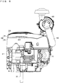
Fig. 5 is a side view (taken from left) of the engine according to the embodiment of the present invention. -
Fig. 6 is a side view (taken from right) of the engine according to the embodiment of the present invention. -
Fig. 7 is a vertical (taken in line A-A inFig. 8 ) sectional view of the engine according to the embodiment of the present invention. -
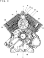
Fig. 8 is a plan view showing a crankcase and a cylinder body. -
Fig. 9 is a bottom view showing the crankcase and the cylinder body. -
Fig. 10 is a plan view showing a crank shaft, pistons and their surrounds. -
Fig. 11 is a view showing the crank shaft, the pistons and their surrounds. -
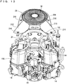
Fig. 12 is an exploded perspective view (from a crankcase side) showing the engine in a state where a second cover is separated from a first cover. -
Fig. 13 is an exploded perspective view (from a cylinder side) showing the engine in a state where the second cover is separated from the first cover. -
Fig. 14(a) is a plan view showing the second cover;Fig. 14(b) is a plan view showing the engine with the second cover removed. - Hereinafter, embodiments of the present invention will be described with reference to the drawings.
- Referring to
Fig. 1 through Fig. 6 , anengine 10 according to an embodiment of the present invention is a vertical, narrow-angle (less than 90 degrees), V-type, two-cylinder, OHV engine (Over Head Valve Engine). Theengine 10 includes acrankcase 12. Twocylinders crankcase 12. Anoil pan 18 is provided below thecrankcase 12. Acrank shaft 20 is provided inside thecrankcase 12 and theoil pan 18 so that its axis direction is in an up-down direction (seeFig. 7 ). Thecrank shaft 20 penetrates thecrankcase 12 and theoil pan 18 in the up-down direction. Referring toFig. 7 , above thecrankcase 12, acooling fan 22 is provided coaxially with thecrank shaft 20. Thecooling fan 22 is driven by thecrank shaft 20, and introduces cooling air from above thecrankcase 12. Acover portion 24 is provided to cover above thecylinders crankcase 12, and thecooling fan 22. Thecover portion 24 includes afirst cover 26 and asecond cover 28 which is attached onto thefirst cover 26. Thesecond cover 28 has anair inlet 30 at a place facing thecooling fan 22, for introducing outside air. Inside thesecond cover 28, there is provided agrass screen 32 which has a mesh structure. Therefore, even if impurities such as grass happen to pass through theair inlet 30, they are caught by thegrass screen 32 and their entry to near thecooling fan 22 is reduced. Therefore, it is possible to take outside air via thesecond cover 28 and thegrass screen 32, into thefirst cover 26. The outside air introduced from theair inlet 30 by driving thecooling fan 22 cools theengine 10. Thefirst cover 26 and thesecond cover 28 will be described later. - Referring to
Fig. 7 through Fig. 9 , thecrankcase 12 has a through-hole 34 penetrated by thecrank shaft 20. Thecrankcase 12 has an upper surface formed with an upward opening, generally gourd-shaped recess 36. In therecess 36, there are provided a first gas/liquid separating chamber 38 and a second gas/liquid separating chamber 40. The first gas/liquid separating chamber 38 and a hollow portion 48 (which will be described later) of thecrankcase 12 communicate with each other via a through-hole 42. The through-hole 42 is opened/closed by areed valve 44 provided in the first gas/liquid separating chamber 38. In a generally center region of the first gas/liquid separating chamber 38, there is provided abearing hole 46 for a cam shaft 106 (which will be described later). In thecrankcase 12, thehollow portion 48 is formed with a downward opening. Thehollow portion 48 serves as an oil chamber. In thehollow portion 48, a third gas/liquid separating chamber 50 is provided. The second gas/liquid separating chamber 40 and the third gas/liquid separating chamber 50 communicate with each other via anoil return hole 52; the first gas/liquid separating chamber 38 and the third gas/liquid separating chamber 50 communicate with each other via anoil return hole 54; and the third gas/liquid separating chamber 50 and theoil pan 18 communicate with each other via anoil return channel 56 provided in thecrankcase 12 and an oil return channel (not illustrated) provided in theoil pan 18. The first gas/liquid separating chamber 38 and the second gas/liquid separating chamber 40 have their upper surfaces provided with alid 58. The third gas/liquid separating chamber 50 has its lower surface provided with alid 60. Thelid 58 has a lower surface formed with awall portion 62, which reduces gas flow from the first gas/liquid separating chamber 38 to the second gas/liquid separating chamber 40. Blowby gas from thehollow portion 48 of thecrankcase 12 is separated into gas and liquid in the first gas/liquid separating chamber 38 and the second gas/liquid separating chamber 40, and further in the third gas/liquid separating chamber 50. As indicated by white arrows inFig. 7 , blowby gas is sent from thehollow portion 48, through the first gas/liquid separating chamber 38, the second gas/liquid separating chamber 40, the third gas/liquid separating chamber 50, agas tube 64, etc. , to an upstream location in an air intake system. Lubricant oil separated in the first gas/liquid separating chamber 38, the second gas/liquid separating chamber 40 and the third gas/liquid separating chamber 50 is returned from the third gas/liquid separating chamber 50, through theoil return channel 56 and so on, to theoil pan 18. - Referring to
Fig. 8 , if theengine 10 is mounted horizontally, lubricant oil from the first gas/liquid separating chamber 38 is returned to theoil pan 18 via a generally V-shapedoil return channel 66. As described, depending on whether theengine 18 is mounted vertically or horizontally, a different oil return channel is used to return lubricant oil to theoil pan 18. - Referring to
Fig. 7 , thesupport member 68 has a through-hole 70 for thecrank shaft 20, a through-hole 72 for a cam shaft 106 (which will be described later), and a through-hole (not illustrated) for a governor shaft 116 (which will be described later). Thesupport member 68 is attached to thecrankcase 12 with unillustrated fasteners such as bolts for example. Thesupport member 68 has dimensions to form a gap between an outer circumference of thesupport member 68 and an end edge of thecrankcase 12, and a gap between the outer circumference of thesupport member 68 and an end edge of theoil pan 18. This allows communication between thecrankcase 12 and theoil pan 18. With the above, an upper region of thecrank shaft 20 is supported by thecrankcase 12 via abearing 74 provided in the through-hole 34 whereas a lower region of thecrank shaft 20 is supported by thesupport member 68 via aball bearing 76 provided in the through-hole 70. In this arrangement, thecrank shaft 20 penetrates thecrankcase 12 and thesupport member 68 in an up-down direction; thesupport member 68 supports one side of thecrank shaft 20 pivotably; and thecrankcase 12 supports another side of thecrank shaft 20 pivotably. Thecrankcase 12 and theoil pan 18 are fixed to each other with unillustrated fasteners. The upper surface openingoil pan 18 is formed with a through-hole 78 to be penetrated by thecrank shaft 20. Anoil seal 80 is placed between thecrank shaft 20 and the through-hole 78. Theoil pan 18 stores lubricant oil for supply to various parts of theengine 10. - Returning to
Fig. 2 andFig. 4 , thecylinder 14 includes acylinder body 82, acylinder head 84 and acylinder head cover 86. Thecylinder 16 includes acylinder body 88, acylinder head 90 and acylinder head cover 92. Referring toFig. 8 andFig. 9 , thecylinder bodies crankcase 12. Each of thecylinder bodies fins - Referring to
Fig. 8 through Fig. 11 ,pistons cylinder bodies pistons rods crank shaft 20 inside thecrankcase 12. Reciprocating movement of thepistons crank shaft 20. Thecrankcase 12 incorporates thecam shaft 106 which moves together with thecrank shaft 20. Referring toFig. 7 , thecam shaft 106 has an end region supported pivotably in thebearing hole 46 by thecrankcase 12 via a film of oil. Thecam shaft 106 has the other end region supported pivotably by thesupport member 68 via aball bearing 108 placed in the through-hole 72. Thecrank shaft 20 is provided with adriving gear 110, whereas thecam shaft 106 is provided with a drivengear 112 which rotates as thedriving gear 110 rotates. Also, agovernor 114 is provided inside thecrankcase 12. Thegovernor 114 is a system for maintaining the number of rotations of theengine 10 within a predetermined range even if there is load fluctuation. Thegovernor 114 has thegovernor shaft 116, which is pressed in an unillustrated through-hole of thesupport member 68. Thegovernor 114 has agovernor gear 118, which is attached pivotably to thegovernor shaft 116, engaged with the drivengear 112, and is rotated as the drivengear 112 rotates. Thecrank shaft 20, thecam shaft 106 and thegovernor shaft 116 which are supported by thesupport member 68 are disposed in parallel (substantially in parallel) to each other. - In the
respective cylinders cylinder bodies crankcase 12 and rocker arm chambers (not illustrated) inside the cylinder head covers 86, 92. - In the
cylinder 14, apush rod 120 and atappet 122 provided at an end region of thepush rod 120 are inserted into the communication path. Thetappet 122 has its tip portion contacted onto anair intake cam 124 of thecam shaft 106 inside thecrankcase 12. Thepush rod 120 has the other end region, which is connected to arocker arm 126 provided inside the rocker arm chamber.Air intake valves rocker arm 126. Theair intake valves push rod 136 and atappet 138 provided at an end region of thepush rod 136 are inserted into the communication path. Thetappet 138 has its tip portion contacted onto anexhaust cam 140 of thecam shaft 106 inside thecrankcase 12. Thepush rod 136 has the other end region, which is connected to arocker arm 142 provided inside the rocker arm chamber. Anexhaust valve 146, which is constantly urged by avalve spring 144 in a closing direction, is driven by therocker arm 142. Theexhaust valve 146 opens/closes an exhaust port 148 (seeFig. 4 ). - Likewise, in the
cylinder 16, apush rod 150 and atappet 152 provided at an end region of thepush rod 150 are inserted into the communication path. Thetappet 152 has its tip portion contacted onto anair intake cam 154 of thecam shaft 106 inside thecrankcase 12. Thepush rod 150 has the other end region, which is connected to arocker arm 156 provided inside the rocker arm chamber.Air intake valves rocker arm 156. Theair intake valves push rod 166 and atappet 168 provided at an end region of thepush rod 166 are inserted into the communication path. Thetappet 168 has its tip portion contacted onto anexhaust cam 170 of thecam shaft 106 inside thecrankcase 12. Thepush rod 166 has the other end region, which is connected to arocker arm 172 provided inside the rocker arm chamber. Anexhaust valve 176, which is constantly urged by avalve spring 174 in a closing direction, is driven by therocker arm 172. Theexhaust valve 176 opens/closes an exhaust port 178 (seeFig. 4 ). - It should be noted here that an
air filter 182 is attached to each air intake port of thecylinders air intake pipe 180 and so on (seeFig. 1 ,Fig. 2 ). Amuffler 188 is connected to theexhaust ports cylinders respective exhaust pipes 184, 186 (seeFig. 14 ). Exhaust gas from theengine 10 is discharged outside via themuffler 188. Theengine 10 is supplied with fuel from an unillustrated fuel tank. Astarter motor 190 rotates thecrank shaft 20 to start theengine 10. - Referring to
Fig. 7 , andFigs. 12 through 14 , thefirst cover 26 and thesecond cover 28 will be described. - The
first cover 26 is formed at a downward opening, and has a firstmain body portion 192 which covers mainly an outer side of thecrankcase 12, and first protrudingportions cylinders main body portion 192 and the first protrudingportions main body portion 192 includes a generally circular first opening 198 (seeFig. 7 ) provided at a position to face the coolingfan 22. The first protrudingportion 194 includes asecond opening 200 provided at a position to face thefins 94. The first protrudingportion 196 includes asecond opening 202 provided at a position to face thefins 96. Thefirst opening 198 is provided with thegrass screen 32. - The
first cover 26 further includes awall portion 204 erected between thefirst opening 198 and thesecond opening 200, and awall portion 206 erected between thefirst opening 198 and thesecond opening 202. Thewall portion 204 is on an edge region of thesecond opening 200, whereas thewall portion 206 is on an edge region of thesecond opening 202. Thefirst cover 26 further includes awall portion 207 erected between thewall portion 204 and thewall portion 206. Thewall portion 207 is disposed along an edge region of thefirst opening 198, connecting an end portion of thewall portion 204 and an end portion of thewall portion 206 to each other. Therefore, thewall portion 204, thewall portion 206 and thewall portion 207 are continuous along thefirst opening 198. - The
second cover 28 includes a platy secondmain body portion 208 for covering thefirst opening 198 of thefirst cover 26, and platy second protrudingportions second openings first cover 26. The secondmain body portion 208 and the second protrudingportions air inlet 30 is positioned in the secondmain body portion 208 to face thefirst opening 198. Thesecond cover 28 is attached to thefirst cover 26 so that the second protrudingportions second openings main body portion 208 covers thefirst opening 198. - The
first cover 26 has a plurality (six, in the present embodiment) of mountingportions 214, whereas thesecond cover 28 has a plurality (six, in the present embodiment) of mountingportions 216. Each mountingportion 214 in thefirst cover 26 is fixed to a corresponding one of the mountingportions 216 in thesecond cover 28 withfasteners 218 such as bolts (seeFig. 1 ), whereby thesecond cover 28 is attached to thefirst cover 26. By attaching/removing thefasteners 218, thesecond cover 28 can be attached to/removed from thefirst cover 26. - Referring also to
Fig. 1 , andFigs. 5 through 7 , attaching thesecond cover 28 to thefirst cover 26forms outlets first cover 26 and thesecond cover 28. In other words, along an outer circumference of thesecond cover 28, theoutlet 220 is between theoutlets outlets air inlet 30. Theoutlet 222 is near thewall portion 204, whereas theoutlet 224 is near thewall portion 206. In the present embodiment, theoutlets second cover 28. However, the invention is not limited to this. Theoutlets first cover 26. - According to the
engine 10, by only removing thesecond cover 28, it becomes possible to blow from thefirst opening 198 and thesecond openings first cover 26 with compressed air for example, to remove debris such as turf grass and other plants easily from areas of the coolingfan 22 andfins cylinders - Since the
first cover 26 has thewall portions first opening 198 and thesecond openings wall portions air inlet 30 into thesecond openings - Since the
wall portions second openings wall portions air inlet 30 into thesecond openings - The
second cover 28 is attached to thefirst cover 26 in such a fashion to form theoutlets wall portions first cover 26 and thesecond cover 28. Therefore, even if debris such as turf grass and other plants enter from theair inlet 30 to between thefirst cover 26 and thesecond cover 28, it is possible to remove the debris out of theoutlets wall portions - It should be noted here that in the embodiment described above, description was made for a case where the present invention is applied to a two-cylinder engine. However, the invention is not limited to this. The present invention is also applicable to a single-cylinder engine or an engine having three or more cylinders.
- The present invention being thus far described in terms of preferred embodiments, it is obvious that these may be varied in many ways within the scope and the spirit of the present invention. The scope of the present invention is only limited by the accompanied claims.
-
- 10
- Engine
- 12
- Crankcase
- 14, 16
- Cylinders
- 20
- Crank shaft
- 22
- Cooling fan
- 26
- First cover
- 28
- Second cover
- 30
- Air inlet
- 94, 96
- Fins
- 198
- First opening
- 200, 202
- Second openings
- 204, 206, 207
- Wall portions
- 220, 222, 224
- Outlets
Claims (4)
- An engine comprising:a crankcase;a cylinder provided in the crankcase and having an outer circumference formed with fins;a crank shaft provided inside the crankcase and penetrating the crankcase;a cooling fan provided on an outer side of the crankcase coaxially with the crank shaft, for introduction of cooling air from the outer side of the crankcase;a first cover provided in such a fashion to cover an outer side of the cylinder and the crankcase, and the cooling fan; anda second cover provided attachably to/detachably from the first cover; whereinthe first cover includes a first opening provided at a position to face the cooling fan and a second opening provided at a position to face the fins; and
the second cover includes an air inlet provided at a position to face the first opening, and is attached to the first cover in such a fashion to cover the first opening and the second opening. - The engine according to Claim 1, wherein the first cover further includes a wall portion erected between the first opening and the second opening.
- The engine according to Claim 2, wherein the wall portion is at an edge region of the second opening.
- The engine according to Claim 2 or 3, wherein the second cover is attached to the first cover in such a fashion to form an outlet for the cooling air near the wall portion between the first cover and the second cover.
Applications Claiming Priority (2)
| Application Number | Priority Date | Filing Date | Title |
|---|---|---|---|
| JP2014091966 | 2014-04-25 | ||
| PCT/JP2015/062619 WO2015163476A1 (en) | 2014-04-25 | 2015-04-24 | Engine |
Publications (3)
| Publication Number | Publication Date |
|---|---|
| EP3135889A1 true EP3135889A1 (en) | 2017-03-01 |
| EP3135889A4 EP3135889A4 (en) | 2018-01-17 |
| EP3135889B1 EP3135889B1 (en) | 2021-07-14 |
Family
ID=54332634
Family Applications (1)
| Application Number | Title | Priority Date | Filing Date |
|---|---|---|---|
| EP15782343.6A Active EP3135889B1 (en) | 2014-04-25 | 2015-04-24 | Engine |
Country Status (6)
| Country | Link |
|---|---|
| US (1) | US10240509B2 (en) |
| EP (1) | EP3135889B1 (en) |
| JP (1) | JP6200074B2 (en) |
| CN (1) | CN106232971B (en) |
| CA (1) | CA2946983A1 (en) |
| WO (1) | WO2015163476A1 (en) |
Families Citing this family (8)
| Publication number | Priority date | Publication date | Assignee | Title |
|---|---|---|---|---|
| US11384711B2 (en) * | 2018-03-30 | 2022-07-12 | Honda Motor Co., Ltd. | Engine |
| US11143099B2 (en) * | 2018-06-15 | 2021-10-12 | Champion Power Equipment, Inc. | Backplate for engine-alternator coupling in standby generator |
| US20220193250A1 (en) | 2018-08-02 | 2022-06-23 | Dyne Therapeutics, Inc. | Muscle targeting complexes and uses thereof for treating facioscapulohumeral muscular dystrophy |
| US12018087B2 (en) | 2018-08-02 | 2024-06-25 | Dyne Therapeutics, Inc. | Muscle-targeting complexes comprising an anti-transferrin receptor antibody linked to an oligonucleotide and methods of delivering oligonucleotide to a subject |
| CN108894886B (en) * | 2018-08-14 | 2024-05-14 | 重庆万虎机电有限责任公司 | Engine of motor tricycle, cylinder head and cooling system thereof |
| USD890210S1 (en) * | 2019-01-16 | 2020-07-14 | Wacker Neuson Produktion GmbH & Co. KG | Internal combustion engine cover |
| JP7593842B2 (en) | 2021-03-17 | 2024-12-03 | 本田技研工業株式会社 | Internal combustion engine |
| USD1076981S1 (en) * | 2022-10-17 | 2025-05-27 | Kawasaki Motors, Ltd. | Internal combustion engine |
Family Cites Families (17)
| Publication number | Priority date | Publication date | Assignee | Title |
|---|---|---|---|---|
| JPS472981Y1 (en) * | 1969-10-27 | 1972-02-01 | ||
| JPS5637058Y2 (en) * | 1976-03-19 | 1981-08-31 | ||
| JPS5924862Y2 (en) * | 1979-03-09 | 1984-07-23 | 株式会社共立 | carburetor intake device |
| JP3140231B2 (en) | 1992-12-28 | 2001-03-05 | 本田技研工業株式会社 | Shroud opening structure for cooling air intake of air-cooled internal combustion engine for vehicles |
| JP3382479B2 (en) * | 1996-12-05 | 2003-03-04 | 本田技研工業株式会社 | Air-cooled engine cooling system |
| US5813384A (en) * | 1997-08-20 | 1998-09-29 | Briggs & Stratton Corporation | Intake system arrangement for V-type engine |
| JP4280345B2 (en) | 1999-01-19 | 2009-06-17 | 本田技研工業株式会社 | General-purpose V-type internal combustion engine |
| JP2001241325A (en) * | 2000-02-29 | 2001-09-07 | Yamaha Motor Co Ltd | Cooling structure of forced air-cooled 4-cycle engine |
| US20040025827A1 (en) | 2002-08-12 | 2004-02-12 | Davis Steven T. | Air cleaner systemwith clear covers for internal combustion engines |
| US6889635B2 (en) | 2003-02-11 | 2005-05-10 | Briggs & Stratton Corporation | Blower housing for internal combustion engine |
| CN100480497C (en) | 2003-07-10 | 2009-04-22 | 雅马哈发动机株式会社 | Engine |
| JP4726766B2 (en) | 2006-11-27 | 2011-07-20 | 本田技研工業株式会社 | Forced air cooling engine |
| TW200827542A (en) | 2006-12-20 | 2008-07-01 | Kwang Yang Motor Co | The structure improvement of the wind guide cover for an engine |
| US7958855B2 (en) * | 2008-05-30 | 2011-06-14 | Kawasaki Jukogyo Kabushiki Kaisha | Air-cooled V-type combustion engine |
| US8656883B2 (en) * | 2011-07-20 | 2014-02-25 | Briggs & Stratton Corporation | Recoil starter assembly for an engine |
| US9500117B2 (en) * | 2013-03-12 | 2016-11-22 | Briggs & Stratton Corporation | Cooling system for air-cooled engine |
| US9964065B2 (en) * | 2015-12-03 | 2018-05-08 | Kawasaki Jukogyo Kabushiki Kaisha | General purpose engine |
-
2015
- 2015-04-24 US US15/306,141 patent/US10240509B2/en active Active
- 2015-04-24 EP EP15782343.6A patent/EP3135889B1/en active Active
- 2015-04-24 CN CN201580022014.6A patent/CN106232971B/en not_active Expired - Fee Related
- 2015-04-24 WO PCT/JP2015/062619 patent/WO2015163476A1/en not_active Ceased
- 2015-04-24 CA CA2946983A patent/CA2946983A1/en not_active Abandoned
- 2015-04-24 JP JP2016515244A patent/JP6200074B2/en active Active
Also Published As
| Publication number | Publication date |
|---|---|
| CA2946983A1 (en) | 2015-10-29 |
| EP3135889A4 (en) | 2018-01-17 |
| JP6200074B2 (en) | 2017-09-20 |
| JPWO2015163476A1 (en) | 2017-04-20 |
| US10240509B2 (en) | 2019-03-26 |
| WO2015163476A1 (en) | 2015-10-29 |
| US20170045015A1 (en) | 2017-02-16 |
| CN106232971A (en) | 2016-12-14 |
| CN106232971B (en) | 2019-09-20 |
| EP3135889B1 (en) | 2021-07-14 |
Similar Documents
| Publication | Publication Date | Title |
|---|---|---|
| EP3135889B1 (en) | Engine | |
| CN102428255B (en) | Four-cycle engine, bush cutter and engine-driven tool having same | |
| US7201132B2 (en) | Combustion engine of vertical shaft type | |
| KR100988442B1 (en) | Camshaft Support Structure for Internal Combustion Engine | |
| JP6207725B2 (en) | engine | |
| JP5393125B2 (en) | Engine lubricating oil cooling structure | |
| CN100348855C (en) | Internal combustion engine inverted crankcase with accessories | |
| JP2009203977A (en) | Breather device for internal combustion engine | |
| US7219629B2 (en) | Breathing system in combustion engine | |
| EP2592243B1 (en) | Lubrication apparatus for four-stroke engine | |
| US10598122B2 (en) | Cylinder head cooling structure | |
| JP5943978B2 (en) | Breather equipment | |
| JPS6141932Y2 (en) | ||
| CA2979032C (en) | Oil mist separation mechanism for internal combustion engine | |
| JP4549871B2 (en) | Internal combustion engine provided with dry sump type lubrication device | |
| JP2011058430A (en) | Engine | |
| JP7081976B2 (en) | Engine with blow-by gas recirculation device | |
| JP2005054702A (en) | Oil return passage structure for internal combustion engine | |
| JP2022083665A (en) | Engine hood and internal combustion engine including the same | |
| WO2015085854A1 (en) | Four-stroke engine | |
| CN103511115B (en) | Engine Fuel Injection System | |
| JP2011043133A (en) | Blow-by gas reducing device for engine | |
| JPH09296735A (en) | Engine for outboard motor |
Legal Events
| Date | Code | Title | Description |
|---|---|---|---|
| STAA | Information on the status of an ep patent application or granted ep patent |
Free format text: STATUS: THE INTERNATIONAL PUBLICATION HAS BEEN MADE |
|
| PUAI | Public reference made under article 153(3) epc to a published international application that has entered the european phase |
Free format text: ORIGINAL CODE: 0009012 |
|
| STAA | Information on the status of an ep patent application or granted ep patent |
Free format text: STATUS: REQUEST FOR EXAMINATION WAS MADE |
|
| 17P | Request for examination filed |
Effective date: 20161026 |
|
| AK | Designated contracting states |
Kind code of ref document: A1 Designated state(s): AL AT BE BG CH CY CZ DE DK EE ES FI FR GB GR HR HU IE IS IT LI LT LU LV MC MK MT NL NO PL PT RO RS SE SI SK SM TR |
|
| AX | Request for extension of the european patent |
Extension state: BA ME |
|
| DAV | Request for validation of the european patent (deleted) | ||
| DAX | Request for extension of the european patent (deleted) | ||
| A4 | Supplementary search report drawn up and despatched |
Effective date: 20171215 |
|
| RIC1 | Information provided on ipc code assigned before grant |
Ipc: F01P 5/06 20060101ALI20171211BHEP Ipc: F02F 7/00 20060101AFI20171211BHEP Ipc: F02F 1/04 20060101ALI20171211BHEP Ipc: F01P 1/02 20060101ALI20171211BHEP |
|
| STAA | Information on the status of an ep patent application or granted ep patent |
Free format text: STATUS: EXAMINATION IS IN PROGRESS |
|
| 17Q | First examination report despatched |
Effective date: 20200609 |
|
| GRAP | Despatch of communication of intention to grant a patent |
Free format text: ORIGINAL CODE: EPIDOSNIGR1 |
|
| STAA | Information on the status of an ep patent application or granted ep patent |
Free format text: STATUS: GRANT OF PATENT IS INTENDED |
|
| INTG | Intention to grant announced |
Effective date: 20210203 |
|
| GRAS | Grant fee paid |
Free format text: ORIGINAL CODE: EPIDOSNIGR3 |
|
| GRAA | (expected) grant |
Free format text: ORIGINAL CODE: 0009210 |
|
| STAA | Information on the status of an ep patent application or granted ep patent |
Free format text: STATUS: THE PATENT HAS BEEN GRANTED |
|
| AK | Designated contracting states |
Kind code of ref document: B1 Designated state(s): AL AT BE BG CH CY CZ DE DK EE ES FI FR GB GR HR HU IE IS IT LI LT LU LV MC MK MT NL NO PL PT RO RS SE SI SK SM TR |
|
| REG | Reference to a national code |
Ref country code: GB Ref legal event code: FG4D |
|
| REG | Reference to a national code |
Ref country code: IE Ref legal event code: FG4D |
|
| REG | Reference to a national code |
Ref country code: DE Ref legal event code: R096 Ref document number: 602015071319 Country of ref document: DE |
|
| REG | Reference to a national code |
Ref country code: AT Ref legal event code: REF Ref document number: 1410846 Country of ref document: AT Kind code of ref document: T Effective date: 20210815 |
|
| REG | Reference to a national code |
Ref country code: LT Ref legal event code: MG9D |
|
| REG | Reference to a national code |
Ref country code: NL Ref legal event code: MP Effective date: 20210714 |
|
| REG | Reference to a national code |
Ref country code: AT Ref legal event code: MK05 Ref document number: 1410846 Country of ref document: AT Kind code of ref document: T Effective date: 20210714 |
|
| PG25 | Lapsed in a contracting state [announced via postgrant information from national office to epo] |
Ref country code: NL Free format text: LAPSE BECAUSE OF FAILURE TO SUBMIT A TRANSLATION OF THE DESCRIPTION OR TO PAY THE FEE WITHIN THE PRESCRIBED TIME-LIMIT Effective date: 20210714 Ref country code: PT Free format text: LAPSE BECAUSE OF FAILURE TO SUBMIT A TRANSLATION OF THE DESCRIPTION OR TO PAY THE FEE WITHIN THE PRESCRIBED TIME-LIMIT Effective date: 20211115 Ref country code: NO Free format text: LAPSE BECAUSE OF FAILURE TO SUBMIT A TRANSLATION OF THE DESCRIPTION OR TO PAY THE FEE WITHIN THE PRESCRIBED TIME-LIMIT Effective date: 20211014 Ref country code: FI Free format text: LAPSE BECAUSE OF FAILURE TO SUBMIT A TRANSLATION OF THE DESCRIPTION OR TO PAY THE FEE WITHIN THE PRESCRIBED TIME-LIMIT Effective date: 20210714 Ref country code: ES Free format text: LAPSE BECAUSE OF FAILURE TO SUBMIT A TRANSLATION OF THE DESCRIPTION OR TO PAY THE FEE WITHIN THE PRESCRIBED TIME-LIMIT Effective date: 20210714 Ref country code: LT Free format text: LAPSE BECAUSE OF FAILURE TO SUBMIT A TRANSLATION OF THE DESCRIPTION OR TO PAY THE FEE WITHIN THE PRESCRIBED TIME-LIMIT Effective date: 20210714 Ref country code: AT Free format text: LAPSE BECAUSE OF FAILURE TO SUBMIT A TRANSLATION OF THE DESCRIPTION OR TO PAY THE FEE WITHIN THE PRESCRIBED TIME-LIMIT Effective date: 20210714 Ref country code: BG Free format text: LAPSE BECAUSE OF FAILURE TO SUBMIT A TRANSLATION OF THE DESCRIPTION OR TO PAY THE FEE WITHIN THE PRESCRIBED TIME-LIMIT Effective date: 20211014 Ref country code: RS Free format text: LAPSE BECAUSE OF FAILURE TO SUBMIT A TRANSLATION OF THE DESCRIPTION OR TO PAY THE FEE WITHIN THE PRESCRIBED TIME-LIMIT Effective date: 20210714 Ref country code: SE Free format text: LAPSE BECAUSE OF FAILURE TO SUBMIT A TRANSLATION OF THE DESCRIPTION OR TO PAY THE FEE WITHIN THE PRESCRIBED TIME-LIMIT Effective date: 20210714 Ref country code: HR Free format text: LAPSE BECAUSE OF FAILURE TO SUBMIT A TRANSLATION OF THE DESCRIPTION OR TO PAY THE FEE WITHIN THE PRESCRIBED TIME-LIMIT Effective date: 20210714 |
|
| PG25 | Lapsed in a contracting state [announced via postgrant information from national office to epo] |
Ref country code: PL Free format text: LAPSE BECAUSE OF FAILURE TO SUBMIT A TRANSLATION OF THE DESCRIPTION OR TO PAY THE FEE WITHIN THE PRESCRIBED TIME-LIMIT Effective date: 20210714 Ref country code: LV Free format text: LAPSE BECAUSE OF FAILURE TO SUBMIT A TRANSLATION OF THE DESCRIPTION OR TO PAY THE FEE WITHIN THE PRESCRIBED TIME-LIMIT Effective date: 20210714 Ref country code: GR Free format text: LAPSE BECAUSE OF FAILURE TO SUBMIT A TRANSLATION OF THE DESCRIPTION OR TO PAY THE FEE WITHIN THE PRESCRIBED TIME-LIMIT Effective date: 20211015 |
|
| REG | Reference to a national code |
Ref country code: DE Ref legal event code: R097 Ref document number: 602015071319 Country of ref document: DE |
|
| PG25 | Lapsed in a contracting state [announced via postgrant information from national office to epo] |
Ref country code: DK Free format text: LAPSE BECAUSE OF FAILURE TO SUBMIT A TRANSLATION OF THE DESCRIPTION OR TO PAY THE FEE WITHIN THE PRESCRIBED TIME-LIMIT Effective date: 20210714 |
|
| PLBE | No opposition filed within time limit |
Free format text: ORIGINAL CODE: 0009261 |
|
| STAA | Information on the status of an ep patent application or granted ep patent |
Free format text: STATUS: NO OPPOSITION FILED WITHIN TIME LIMIT |
|
| PG25 | Lapsed in a contracting state [announced via postgrant information from national office to epo] |
Ref country code: SM Free format text: LAPSE BECAUSE OF FAILURE TO SUBMIT A TRANSLATION OF THE DESCRIPTION OR TO PAY THE FEE WITHIN THE PRESCRIBED TIME-LIMIT Effective date: 20210714 Ref country code: SK Free format text: LAPSE BECAUSE OF FAILURE TO SUBMIT A TRANSLATION OF THE DESCRIPTION OR TO PAY THE FEE WITHIN THE PRESCRIBED TIME-LIMIT Effective date: 20210714 Ref country code: RO Free format text: LAPSE BECAUSE OF FAILURE TO SUBMIT A TRANSLATION OF THE DESCRIPTION OR TO PAY THE FEE WITHIN THE PRESCRIBED TIME-LIMIT Effective date: 20210714 Ref country code: EE Free format text: LAPSE BECAUSE OF FAILURE TO SUBMIT A TRANSLATION OF THE DESCRIPTION OR TO PAY THE FEE WITHIN THE PRESCRIBED TIME-LIMIT Effective date: 20210714 Ref country code: CZ Free format text: LAPSE BECAUSE OF FAILURE TO SUBMIT A TRANSLATION OF THE DESCRIPTION OR TO PAY THE FEE WITHIN THE PRESCRIBED TIME-LIMIT Effective date: 20210714 Ref country code: AL Free format text: LAPSE BECAUSE OF FAILURE TO SUBMIT A TRANSLATION OF THE DESCRIPTION OR TO PAY THE FEE WITHIN THE PRESCRIBED TIME-LIMIT Effective date: 20210714 |
|
| 26N | No opposition filed |
Effective date: 20220419 |
|
| PG25 | Lapsed in a contracting state [announced via postgrant information from national office to epo] |
Ref country code: IT Free format text: LAPSE BECAUSE OF FAILURE TO SUBMIT A TRANSLATION OF THE DESCRIPTION OR TO PAY THE FEE WITHIN THE PRESCRIBED TIME-LIMIT Effective date: 20210714 |
|
| REG | Reference to a national code |
Ref country code: DE Ref legal event code: R119 Ref document number: 602015071319 Country of ref document: DE |
|
| REG | Reference to a national code |
Ref country code: CH Ref legal event code: PL |
|
| GBPC | Gb: european patent ceased through non-payment of renewal fee |
Effective date: 20220424 |
|
| REG | Reference to a national code |
Ref country code: BE Ref legal event code: MM Effective date: 20220430 |
|
| PG25 | Lapsed in a contracting state [announced via postgrant information from national office to epo] |
Ref country code: MC Free format text: LAPSE BECAUSE OF FAILURE TO SUBMIT A TRANSLATION OF THE DESCRIPTION OR TO PAY THE FEE WITHIN THE PRESCRIBED TIME-LIMIT Effective date: 20210714 Ref country code: LU Free format text: LAPSE BECAUSE OF NON-PAYMENT OF DUE FEES Effective date: 20220424 Ref country code: LI Free format text: LAPSE BECAUSE OF NON-PAYMENT OF DUE FEES Effective date: 20220430 Ref country code: GB Free format text: LAPSE BECAUSE OF NON-PAYMENT OF DUE FEES Effective date: 20220424 Ref country code: FR Free format text: LAPSE BECAUSE OF NON-PAYMENT OF DUE FEES Effective date: 20220430 Ref country code: DE Free format text: LAPSE BECAUSE OF NON-PAYMENT OF DUE FEES Effective date: 20221103 Ref country code: CH Free format text: LAPSE BECAUSE OF NON-PAYMENT OF DUE FEES Effective date: 20220430 |
|
| PG25 | Lapsed in a contracting state [announced via postgrant information from national office to epo] |
Ref country code: BE Free format text: LAPSE BECAUSE OF NON-PAYMENT OF DUE FEES Effective date: 20220430 |
|
| PG25 | Lapsed in a contracting state [announced via postgrant information from national office to epo] |
Ref country code: IE Free format text: LAPSE BECAUSE OF NON-PAYMENT OF DUE FEES Effective date: 20220424 |
|
| PG25 | Lapsed in a contracting state [announced via postgrant information from national office to epo] |
Ref country code: HU Free format text: LAPSE BECAUSE OF FAILURE TO SUBMIT A TRANSLATION OF THE DESCRIPTION OR TO PAY THE FEE WITHIN THE PRESCRIBED TIME-LIMIT; INVALID AB INITIO Effective date: 20150424 |
|
| PG25 | Lapsed in a contracting state [announced via postgrant information from national office to epo] |
Ref country code: MK Free format text: LAPSE BECAUSE OF FAILURE TO SUBMIT A TRANSLATION OF THE DESCRIPTION OR TO PAY THE FEE WITHIN THE PRESCRIBED TIME-LIMIT Effective date: 20210714 Ref country code: CY Free format text: LAPSE BECAUSE OF FAILURE TO SUBMIT A TRANSLATION OF THE DESCRIPTION OR TO PAY THE FEE WITHIN THE PRESCRIBED TIME-LIMIT Effective date: 20210714 |
|
| PG25 | Lapsed in a contracting state [announced via postgrant information from national office to epo] |
Ref country code: TR Free format text: LAPSE BECAUSE OF FAILURE TO SUBMIT A TRANSLATION OF THE DESCRIPTION OR TO PAY THE FEE WITHIN THE PRESCRIBED TIME-LIMIT Effective date: 20210714 |
|
| PG25 | Lapsed in a contracting state [announced via postgrant information from national office to epo] |
Ref country code: MT Free format text: LAPSE BECAUSE OF FAILURE TO SUBMIT A TRANSLATION OF THE DESCRIPTION OR TO PAY THE FEE WITHIN THE PRESCRIBED TIME-LIMIT Effective date: 20210714 |