EP3135825A1 - Apparatus for calculating operational time of hybrid construction machine and method therefor - Google Patents
Apparatus for calculating operational time of hybrid construction machine and method therefor Download PDFInfo
- Publication number
- EP3135825A1 EP3135825A1 EP14890182.0A EP14890182A EP3135825A1 EP 3135825 A1 EP3135825 A1 EP 3135825A1 EP 14890182 A EP14890182 A EP 14890182A EP 3135825 A1 EP3135825 A1 EP 3135825A1
- Authority
- EP
- European Patent Office
- Prior art keywords
- converter
- inverter
- ess
- current
- operation time
- Prior art date
- Legal status (The legal status is an assumption and is not a legal conclusion. Google has not performed a legal analysis and makes no representation as to the accuracy of the status listed.)
- Granted
Links
Images

Classifications
-
- B—PERFORMING OPERATIONS; TRANSPORTING
- B60—VEHICLES IN GENERAL
- B60W—CONJOINT CONTROL OF VEHICLE SUB-UNITS OF DIFFERENT TYPE OR DIFFERENT FUNCTION; CONTROL SYSTEMS SPECIALLY ADAPTED FOR HYBRID VEHICLES; ROAD VEHICLE DRIVE CONTROL SYSTEMS FOR PURPOSES NOT RELATED TO THE CONTROL OF A PARTICULAR SUB-UNIT
- B60W20/00—Control systems specially adapted for hybrid vehicles
- B60W20/10—Controlling the power contribution of each of the prime movers to meet required power demand
-
- B—PERFORMING OPERATIONS; TRANSPORTING
- B60—VEHICLES IN GENERAL
- B60K—ARRANGEMENT OR MOUNTING OF PROPULSION UNITS OR OF TRANSMISSIONS IN VEHICLES; ARRANGEMENT OR MOUNTING OF PLURAL DIVERSE PRIME-MOVERS IN VEHICLES; AUXILIARY DRIVES FOR VEHICLES; INSTRUMENTATION OR DASHBOARDS FOR VEHICLES; ARRANGEMENTS IN CONNECTION WITH COOLING, AIR INTAKE, GAS EXHAUST OR FUEL SUPPLY OF PROPULSION UNITS IN VEHICLES
- B60K6/00—Arrangement or mounting of plural diverse prime-movers for mutual or common propulsion, e.g. hybrid propulsion systems comprising electric motors and internal combustion engines
- B60K6/20—Arrangement or mounting of plural diverse prime-movers for mutual or common propulsion, e.g. hybrid propulsion systems comprising electric motors and internal combustion engines the prime-movers consisting of electric motors and internal combustion engines, e.g. HEVs
- B60K6/22—Arrangement or mounting of plural diverse prime-movers for mutual or common propulsion, e.g. hybrid propulsion systems comprising electric motors and internal combustion engines the prime-movers consisting of electric motors and internal combustion engines, e.g. HEVs characterised by apparatus, components or means specially adapted for HEVs
- B60K6/26—Arrangement or mounting of plural diverse prime-movers for mutual or common propulsion, e.g. hybrid propulsion systems comprising electric motors and internal combustion engines the prime-movers consisting of electric motors and internal combustion engines, e.g. HEVs characterised by apparatus, components or means specially adapted for HEVs characterised by the motors or the generators
-
- B—PERFORMING OPERATIONS; TRANSPORTING
- B60—VEHICLES IN GENERAL
- B60K—ARRANGEMENT OR MOUNTING OF PROPULSION UNITS OR OF TRANSMISSIONS IN VEHICLES; ARRANGEMENT OR MOUNTING OF PLURAL DIVERSE PRIME-MOVERS IN VEHICLES; AUXILIARY DRIVES FOR VEHICLES; INSTRUMENTATION OR DASHBOARDS FOR VEHICLES; ARRANGEMENTS IN CONNECTION WITH COOLING, AIR INTAKE, GAS EXHAUST OR FUEL SUPPLY OF PROPULSION UNITS IN VEHICLES
- B60K6/00—Arrangement or mounting of plural diverse prime-movers for mutual or common propulsion, e.g. hybrid propulsion systems comprising electric motors and internal combustion engines
- B60K6/20—Arrangement or mounting of plural diverse prime-movers for mutual or common propulsion, e.g. hybrid propulsion systems comprising electric motors and internal combustion engines the prime-movers consisting of electric motors and internal combustion engines, e.g. HEVs
- B60K6/22—Arrangement or mounting of plural diverse prime-movers for mutual or common propulsion, e.g. hybrid propulsion systems comprising electric motors and internal combustion engines the prime-movers consisting of electric motors and internal combustion engines, e.g. HEVs characterised by apparatus, components or means specially adapted for HEVs
- B60K6/28—Arrangement or mounting of plural diverse prime-movers for mutual or common propulsion, e.g. hybrid propulsion systems comprising electric motors and internal combustion engines the prime-movers consisting of electric motors and internal combustion engines, e.g. HEVs characterised by apparatus, components or means specially adapted for HEVs characterised by the electric energy storing means, e.g. batteries or capacitors
-
- E—FIXED CONSTRUCTIONS
- E02—HYDRAULIC ENGINEERING; FOUNDATIONS; SOIL SHIFTING
- E02F—DREDGING; SOIL-SHIFTING
- E02F9/00—Component parts of dredgers or soil-shifting machines, not restricted to one of the kinds covered by groups E02F3/00 - E02F7/00
- E02F9/20—Drives; Control devices
- E02F9/2058—Electric or electro-mechanical or mechanical control devices of vehicle sub-units
- E02F9/2062—Control of propulsion units
- E02F9/2075—Control of propulsion units of the hybrid type
-
- E—FIXED CONSTRUCTIONS
- E02—HYDRAULIC ENGINEERING; FOUNDATIONS; SOIL SHIFTING
- E02F—DREDGING; SOIL-SHIFTING
- E02F9/00—Component parts of dredgers or soil-shifting machines, not restricted to one of the kinds covered by groups E02F3/00 - E02F7/00
- E02F9/20—Drives; Control devices
- E02F9/2058—Electric or electro-mechanical or mechanical control devices of vehicle sub-units
- E02F9/2091—Control of energy storage means for electrical energy, e.g. battery or capacitors
-
- E—FIXED CONSTRUCTIONS
- E02—HYDRAULIC ENGINEERING; FOUNDATIONS; SOIL SHIFTING
- E02F—DREDGING; SOIL-SHIFTING
- E02F9/00—Component parts of dredgers or soil-shifting machines, not restricted to one of the kinds covered by groups E02F3/00 - E02F7/00
- E02F9/26—Indicating devices
- E02F9/267—Diagnosing or detecting failure of vehicles
-
- H—ELECTRICITY
- H01—ELECTRIC ELEMENTS
- H01M—PROCESSES OR MEANS, e.g. BATTERIES, FOR THE DIRECT CONVERSION OF CHEMICAL ENERGY INTO ELECTRICAL ENERGY
- H01M10/00—Secondary cells; Manufacture thereof
- H01M10/42—Methods or arrangements for servicing or maintenance of secondary cells or secondary half-cells
- H01M10/48—Accumulators combined with arrangements for measuring, testing or indicating the condition of cells, e.g. the level or density of the electrolyte
-
- B—PERFORMING OPERATIONS; TRANSPORTING
- B60—VEHICLES IN GENERAL
- B60K—ARRANGEMENT OR MOUNTING OF PROPULSION UNITS OR OF TRANSMISSIONS IN VEHICLES; ARRANGEMENT OR MOUNTING OF PLURAL DIVERSE PRIME-MOVERS IN VEHICLES; AUXILIARY DRIVES FOR VEHICLES; INSTRUMENTATION OR DASHBOARDS FOR VEHICLES; ARRANGEMENTS IN CONNECTION WITH COOLING, AIR INTAKE, GAS EXHAUST OR FUEL SUPPLY OF PROPULSION UNITS IN VEHICLES
- B60K25/00—Auxiliary drives
- B60K25/02—Auxiliary drives directly from an engine shaft
-
- B—PERFORMING OPERATIONS; TRANSPORTING
- B60—VEHICLES IN GENERAL
- B60K—ARRANGEMENT OR MOUNTING OF PROPULSION UNITS OR OF TRANSMISSIONS IN VEHICLES; ARRANGEMENT OR MOUNTING OF PLURAL DIVERSE PRIME-MOVERS IN VEHICLES; AUXILIARY DRIVES FOR VEHICLES; INSTRUMENTATION OR DASHBOARDS FOR VEHICLES; ARRANGEMENTS IN CONNECTION WITH COOLING, AIR INTAKE, GAS EXHAUST OR FUEL SUPPLY OF PROPULSION UNITS IN VEHICLES
- B60K6/00—Arrangement or mounting of plural diverse prime-movers for mutual or common propulsion, e.g. hybrid propulsion systems comprising electric motors and internal combustion engines
- B60K6/20—Arrangement or mounting of plural diverse prime-movers for mutual or common propulsion, e.g. hybrid propulsion systems comprising electric motors and internal combustion engines the prime-movers consisting of electric motors and internal combustion engines, e.g. HEVs
- B60K6/42—Arrangement or mounting of plural diverse prime-movers for mutual or common propulsion, e.g. hybrid propulsion systems comprising electric motors and internal combustion engines the prime-movers consisting of electric motors and internal combustion engines, e.g. HEVs characterised by the architecture of the hybrid electric vehicle
- B60K6/46—Series type
-
- B—PERFORMING OPERATIONS; TRANSPORTING
- B60—VEHICLES IN GENERAL
- B60Y—INDEXING SCHEME RELATING TO ASPECTS CROSS-CUTTING VEHICLE TECHNOLOGY
- B60Y2200/00—Type of vehicle
- B60Y2200/40—Special vehicles
- B60Y2200/41—Construction vehicles, e.g. graders, excavators
-
- B—PERFORMING OPERATIONS; TRANSPORTING
- B60—VEHICLES IN GENERAL
- B60Y—INDEXING SCHEME RELATING TO ASPECTS CROSS-CUTTING VEHICLE TECHNOLOGY
- B60Y2200/00—Type of vehicle
- B60Y2200/90—Vehicles comprising electric prime movers
- B60Y2200/92—Hybrid vehicles
-
- B—PERFORMING OPERATIONS; TRANSPORTING
- B60—VEHICLES IN GENERAL
- B60Y—INDEXING SCHEME RELATING TO ASPECTS CROSS-CUTTING VEHICLE TECHNOLOGY
- B60Y2300/00—Purposes or special features of road vehicle drive control systems
- B60Y2300/60—Control of electric machines, e.g. problems related to electric motors or generators
-
- B—PERFORMING OPERATIONS; TRANSPORTING
- B60—VEHICLES IN GENERAL
- B60Y—INDEXING SCHEME RELATING TO ASPECTS CROSS-CUTTING VEHICLE TECHNOLOGY
- B60Y2300/00—Purposes or special features of road vehicle drive control systems
- B60Y2300/91—Battery charging
-
- B—PERFORMING OPERATIONS; TRANSPORTING
- B60—VEHICLES IN GENERAL
- B60Y—INDEXING SCHEME RELATING TO ASPECTS CROSS-CUTTING VEHICLE TECHNOLOGY
- B60Y2400/00—Special features of vehicle units
- B60Y2400/11—Electric energy storages
- B60Y2400/112—Batteries
-
- B—PERFORMING OPERATIONS; TRANSPORTING
- B60—VEHICLES IN GENERAL
- B60Y—INDEXING SCHEME RELATING TO ASPECTS CROSS-CUTTING VEHICLE TECHNOLOGY
- B60Y2400/00—Special features of vehicle units
- B60Y2400/60—Electric Machines, e.g. motors or generators
-
- Y—GENERAL TAGGING OF NEW TECHNOLOGICAL DEVELOPMENTS; GENERAL TAGGING OF CROSS-SECTIONAL TECHNOLOGIES SPANNING OVER SEVERAL SECTIONS OF THE IPC; TECHNICAL SUBJECTS COVERED BY FORMER USPC CROSS-REFERENCE ART COLLECTIONS [XRACs] AND DIGESTS
- Y02—TECHNOLOGIES OR APPLICATIONS FOR MITIGATION OR ADAPTATION AGAINST CLIMATE CHANGE
- Y02E—REDUCTION OF GREENHOUSE GAS [GHG] EMISSIONS, RELATED TO ENERGY GENERATION, TRANSMISSION OR DISTRIBUTION
- Y02E60/00—Enabling technologies; Technologies with a potential or indirect contribution to GHG emissions mitigation
- Y02E60/10—Energy storage using batteries
-
- Y—GENERAL TAGGING OF NEW TECHNOLOGICAL DEVELOPMENTS; GENERAL TAGGING OF CROSS-SECTIONAL TECHNOLOGIES SPANNING OVER SEVERAL SECTIONS OF THE IPC; TECHNICAL SUBJECTS COVERED BY FORMER USPC CROSS-REFERENCE ART COLLECTIONS [XRACs] AND DIGESTS
- Y10—TECHNICAL SUBJECTS COVERED BY FORMER USPC
- Y10S—TECHNICAL SUBJECTS COVERED BY FORMER USPC CROSS-REFERENCE ART COLLECTIONS [XRACs] AND DIGESTS
- Y10S903/00—Hybrid electric vehicles, HEVS
- Y10S903/902—Prime movers comprising electrical and internal combustion motors
- Y10S903/903—Prime movers comprising electrical and internal combustion motors having energy storing means, e.g. battery, capacitor
- Y10S903/904—Component specially adapted for hev
- Y10S903/906—Motor or generator
-
- Y—GENERAL TAGGING OF NEW TECHNOLOGICAL DEVELOPMENTS; GENERAL TAGGING OF CROSS-SECTIONAL TECHNOLOGIES SPANNING OVER SEVERAL SECTIONS OF THE IPC; TECHNICAL SUBJECTS COVERED BY FORMER USPC CROSS-REFERENCE ART COLLECTIONS [XRACs] AND DIGESTS
- Y10—TECHNICAL SUBJECTS COVERED BY FORMER USPC
- Y10S—TECHNICAL SUBJECTS COVERED BY FORMER USPC CROSS-REFERENCE ART COLLECTIONS [XRACs] AND DIGESTS
- Y10S903/00—Hybrid electric vehicles, HEVS
- Y10S903/902—Prime movers comprising electrical and internal combustion motors
- Y10S903/903—Prime movers comprising electrical and internal combustion motors having energy storing means, e.g. battery, capacitor
- Y10S903/904—Component specially adapted for hev
- Y10S903/907—Electricity storage, e.g. battery, capacitor
Definitions
- the present invention relates to an apparatus for calculating operational time of hybrid construction machine and method therefor.
- an operation time of a machine is calculated using an output from an alternator connected mechanically with an engine. That is, a conventional construction machine recognizes the operation of a machine only when an engine is operated, and sends the operation time of the machine to a display. An operator confirms the operation time displayed as described above for the maintenance of the components of the machine.
- a conventional technique makes it difficult to predict the individual operation time of the respective main component and manage the maintenance period of the respective component. Accordingly, a conventional technique makes it difficult for an operator to efficiently maintain the components, and an operator may miss the proper time of replacing the components. This causes the operator the unnecessary maintenance costs, and the machine that has not been properly maintained causes trouble or requires the additional maintenance, which lowers the operational efficiency of the machine.
- the present invention has been made to solve the aforementioned problems occurring in the related art, and it is an object of the present invention to improve the productivity of a hybrid construction machine by minimizing the down time and the additionally required maintenance time for the main components of the hybrid construction machine, which is enabled by calculating the accurate operation time of the respective component, and thereby maximizing the operation period of the machine.
- a hybrid construction machine having at least one of electric work device in which the current flow of the respective work device is measured and the operation time is calculated as it recognizes that the corresponding work device is under operation when the current flow of the respective work device exceeds a certain value.
- the operator can confirm the operation time of the respective component, and according to the embodiment of the present invention, the maintenance alert can be reported when the operation time of the respective component gets close to the predetermined maintenance period. This facilitates the maintenance of the respective work device (component) embedded in the hybrid construction machine, further improves the operability of the machine and contributes to the increased productivity of the hybrid construction machine.
- the problem can be solved that could occur when the conventional calculation technique is applied for calculating the operation time of the electric hybrid construction machine.
- the hybrid construction machine in order to assess the actual operation time of the respective work device, the current flowing between the respective EM (Electric Motor) and inverter is measured and thereby the individual operation time of the work device connected with EM can be calculated.
- the hybrid construction machine according to the embodiment of the present invention can calculate the operation time of the respective work device, and can report the result to the operator so that the operator can maintain the work devices properly in time.
- the maintenance alert can be reported to the operator so that the operator can take the maintenance action when the calculated operation time gets close to the maintenance period.
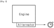
- Fig. 1 represents the diagram illustrating the conventional measurement method of the operation time by the alternator connected to the engine.
- a construction machine uses the power generated only by an engine as a power source. Accordingly, in order to obtain the operation time of the construction machine, the output generated by the alternator connected with the engine has been measured.
- this technique is difficult to be applied for the hybrid scheme utilizing ESS (Energy Storage System) and all sorts of the electric motor.
- ESS Electronicgy Storage System
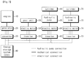
- Fig. 2 is a schematic diagram of a hybrid construction machine according to an embodiment of the present invention.
- the hybrid construction machine according to Fig. 2 comprises at least one of work device operated by a generator and an electric motor which are mechanically connected with an engine, and may further comprise at least one of ESS for storing the energy generated by the generator and the work device, which supply the energy to the electric motor for the operation of the work device.
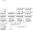
- Fig. 3 is a mimetic diagram to calculate the operation time of the respective component embedded in a hybrid construction machine according to an embodiment of the present invention.
- a hybrid construction machine comprises an engine (10), a generator (20) connected to the engine, and a converter (30) that converts the energy generated by the generator for allowing the energy to be stored in ESS (40).
- the engine (10) and the generator (20) is connected mechanically with each other, while the connection between the generator (20) and the converter (30) as well as the connection between the converter (30) and ESS (40) are made electrically so that the current over a certain level can flow between the respective components when the respective component is operated.
- the operation time of the respective component can be calculated by measuring the current generated in the operation.
- a converter current detector (32) detects the current flowing between the generator and the converter.
- the electric lines (converter lines) flowing through the converter can exist in a plurality, and can be joined at around the ESS, in which the current sensors may be arranged in a plurality of converter lines.
- the converter current detector (32) can be positioned either between the converter (30) and the generator (20) or between the converter (30) and ESS.
- ESS current detector is positioned between the converter (30) and ESS, and detects the current flowing between the converter (30) and ESS.
- a hybrid construction machine comprises a processing unit (80) that receives the currents detected from the converter current detector (32) as well as ESS current detector (42) and calculates the operation time of the respective component; and a display unit (90) displaying the operation time of the respective component.
- the processing unit calculates the RMS (root mean square) of the currents considering the currents of opposite directions, and sets the predetermined dead zone to ignore the line noise and the measurement error.
- the processing unit sets the dead zone as 'a', and counts the operation time as the time for which the current (i) is kept above 0+a.
- the processing unit sets the current level of 'a' that can be generated by the line noise and the error, which also may be set by the operator, manager, or repair man.
- the processing unit When RMS value of the current detected by the converter current detector is more than 0+a, the processing unit recognizes that the converter is under operation and counts the operation time of the converter. In other words, if RMS(i1) > 0+a is satisfied assuming that the current flowing in the converter current detector is i1, the processing unit recognizes that the converter is under operation.
- a hybrid construction machine comprises further an inverter (50) connected to ESS, and an electric motor (54) connected to the inverter, wherein a gear unit (56) may be connected to the electric motor for the driving and turning of the construction machine.
- An inverter current detector (52) is positioned between the inverter and the electric motor and detects the current flowing between the inverter and the electric motor, while the processing unit (80) receives the current detected from the inverter current detector and calculates the operation time of the respective component.
- the hybrid construction machine may comprise a display unit (90) displaying the operation time of the respective component.
- the processing unit sets the current level of 'a' that can be generated by the line noise and the error, and when RMS value of the current detected by the inverter current detector is more than 0+a, the processing unit recognizes that inverter is under operation and counts the operation times of inverter, electric motor and gear unit.
- a hybrid construction machine may comprise further at least one of the inverter (60, 70) connected to ESS, at least one of the electric motor (64, 74) connected respectively to the inverter, at least one of the hydraulic pump (66, 76) connected respectively to the electric motor and at least one of the cylinder (68, 78) respectively connected to the hydraulic pump.
- the inverter current detectors (62, 72) are positioned between the at least one of the inverter and the at least one of the electric motor, respectively, and detect the current flowing between the respective inverter and the respective electric motor.
- the processing unit (80) receives the current detected from the inverter current detector and calculates the operation time of the respective component, and a display unit (90) displays the operation time of the respective component.
- the operation times of the work components such as arm or bucket of the construction machine that are connected to the hydraulic pump can be calculated by measuring the current flowing between the inverter and the electric motor. This is made possible because the hydraulic pump and the cylinder are operated with each other when the electric motor is operated by the inverter.
- the processing unit sets the current level of 'a' that can be generated by the line noise and the error, and when RMS value of the current detected by the inverter current detector is more than 0+a, the processing unit recognizes that inverter is under operation and can count the operation times of inverter, electric motor, hydraulic pump and cylinder.
- Fig. 4 is a schematic diagram to process the operation time of the component in the processing unit according to an embodiment of the present invention.
- a processing unit of a hybrid construction machine keeps monitoring the current detected by the detector, stores the calculated operation time (t), and calculates the accumulated operation time (t). Also, if RMS of the detected current (i) is less than 0+a, the calculation of the operation time (t) is stopped. At this time, the detected currents of the respective component can be denoted as i1, i2, 13,...in, and the operation times of the respective component can be denoted as t1, t2, t3,...tn.
- the operation time can be received by the processing unit on the operator input and the operation times of the main components (elements) can be displayed as the operator wants to.
- the processing unit may either display the maintenance alert on the display or transmit the maintenance alert to the management server by using the wireline or wireless communication devices. This efficiently helps managing the maintenance period of the respective component.
- the maintenance period can be predetermined for the respective component by the manager or the repair man.
Landscapes
- Engineering & Computer Science (AREA)
- Mining & Mineral Resources (AREA)
- Structural Engineering (AREA)
- General Engineering & Computer Science (AREA)
- Civil Engineering (AREA)
- Chemical & Material Sciences (AREA)
- Transportation (AREA)
- Mechanical Engineering (AREA)
- Combustion & Propulsion (AREA)
- General Chemical & Material Sciences (AREA)
- Electrochemistry (AREA)
- Chemical Kinetics & Catalysis (AREA)
- Power Engineering (AREA)
- Manufacturing & Machinery (AREA)
- Automation & Control Theory (AREA)
- Operation Control Of Excavators (AREA)
- Component Parts Of Construction Machinery (AREA)
- Inverter Devices (AREA)
- Control Of Electric Motors In General (AREA)
Abstract
Description
- The present invention relates to an apparatus for calculating operational time of hybrid construction machine and method therefor.
- As shown in
Fig. 1 in case of the general construction machine, an operation time of a machine is calculated using an output from an alternator connected mechanically with an engine. That is, a conventional construction machine recognizes the operation of a machine only when an engine is operated, and sends the operation time of the machine to a display. An operator confirms the operation time displayed as described above for the maintenance of the components of the machine. - When such a system is applied for an electric hybrid construction machine as shown in
Fig 2 , it is impossible to calculate accurately the operation time of component which is not directly associated with an engine, since the electric hybrid construction machine can be operated only by an energy stored in ESS (Energy Storage System) that is independent of the operation state of the engine. For example, in case of the single operation of driving only EMI (Electrical Motor), it is impossible to calculate the operation time of the individual work device (component) using the general calculation method ofFig. 1 . - Consequently, a conventional technique makes it difficult to predict the individual operation time of the respective main component and manage the maintenance period of the respective component. Accordingly, a conventional technique makes it difficult for an operator to efficiently maintain the components, and an operator may miss the proper time of replacing the components. This causes the operator the unnecessary maintenance costs, and the machine that has not been properly maintained causes trouble or requires the additional maintenance, which lowers the operational efficiency of the machine.
- Accordingly, the present invention has been made to solve the aforementioned problems occurring in the related art, and it is an object of the present invention to improve the productivity of a hybrid construction machine by minimizing the down time and the additionally required maintenance time for the main components of the hybrid construction machine, which is enabled by calculating the accurate operation time of the respective component, and thereby maximizing the operation period of the machine.
- To achieve the above and other objects, in accordance with an embodiment of the present invention, there is provided a hybrid construction machine having at least one of electric work device in which the current flow of the respective work device is measured and the operation time is calculated as it recognizes that the corresponding work device is under operation when the current flow of the respective work device exceeds a certain value. The operator can confirm the operation time of the respective component, and according to the embodiment of the present invention, the maintenance alert can be reported when the operation time of the respective component gets close to the predetermined maintenance period. This facilitates the maintenance of the respective work device (component) embedded in the hybrid construction machine, further improves the operability of the machine and contributes to the increased productivity of the hybrid construction machine.
- According to the embodiment of the present invention, the problem can be solved that could occur when the conventional calculation technique is applied for calculating the operation time of the electric hybrid construction machine. For example, in order to assess the actual operation time of the respective work device, the current flowing between the respective EM (Electric Motor) and inverter is measured and thereby the individual operation time of the work device connected with EM can be calculated. As a result, the hybrid construction machine according to the embodiment of the present invention can calculate the operation time of the respective work device, and can report the result to the operator so that the operator can maintain the work devices properly in time.
- Furthermore, by comparing the calculated operation time of the respective component with the predetermined maintenance period of the component, the maintenance alert can be reported to the operator so that the operator can take the maintenance action when the calculated operation time gets close to the maintenance period.
-
-
Fig. 1 represents the diagram illustrating the conventional measurement method of the operation time by the alternator connected to the engine. -
Fig. 2 is a schematic diagram of a hybrid construction machine according to an embodiment of the present invention. -
Fig. 3 is a mimetic diagram to calculate the operation time of the respective component embedded in a hybrid construction machine according to an embodiment of the present invention. -
Fig. 4 is a schematic diagram to process the operation time of the component in the processing unit according to an embodiment of the present invention. - Hereinafter, the present invention will be described in detail with reference to the accompanying drawings.
- Although the present invention has been described with reference to the preferred embodiment in the attached figures, it is to be understood that various equivalent modifications and variations of the embodiments can be made by a person having an ordinary skill in the art without departing from the spirit and scope of the present invention as recited in the claims.
- In order to explain clearly the present invention, the irrelevant parts have been omitted, and like reference numerals designate like elements throughout the specification.
- Throughout the specification, unless explicitly described to the contrary, the "comprise" will be understood to imply the inclusion of stated elements but not the exclusion of any other elements.
-
Fig. 1 represents the diagram illustrating the conventional measurement method of the operation time by the alternator connected to the engine. In the conventional technique, it has been common that a construction machine uses the power generated only by an engine as a power source. Accordingly, in order to obtain the operation time of the construction machine, the output generated by the alternator connected with the engine has been measured. However, this technique is difficult to be applied for the hybrid scheme utilizing ESS (Energy Storage System) and all sorts of the electric motor. -
Fig. 2 is a schematic diagram of a hybrid construction machine according to an embodiment of the present invention. The hybrid construction machine according toFig. 2 comprises at least one of work device operated by a generator and an electric motor which are mechanically connected with an engine, and may further comprise at least one of ESS for storing the energy generated by the generator and the work device, which supply the energy to the electric motor for the operation of the work device. -
Fig. 3 is a mimetic diagram to calculate the operation time of the respective component embedded in a hybrid construction machine according to an embodiment of the present invention. - A hybrid construction machine according to an embodiment of the present invention comprises an engine (10), a generator (20) connected to the engine, and a converter (30) that converts the energy generated by the generator for allowing the energy to be stored in ESS (40). The engine (10) and the generator (20) is connected mechanically with each other, while the connection between the generator (20) and the converter (30) as well as the connection between the converter (30) and ESS (40) are made electrically so that the current over a certain level can flow between the respective components when the respective component is operated. Thus, the operation time of the respective component can be calculated by measuring the current generated in the operation.
- According to an embodiment, a converter current detector (32) detects the current flowing between the generator and the converter. The electric lines (converter lines) flowing through the converter can exist in a plurality, and can be joined at around the ESS, in which the current sensors may be arranged in a plurality of converter lines. Accordingly, the converter current detector (32) can be positioned either between the converter (30) and the generator (20) or between the converter (30) and ESS. ESS current detector is positioned between the converter (30) and ESS, and detects the current flowing between the converter (30) and ESS. A hybrid construction machine according to an embodiment of the present invention comprises a processing unit (80) that receives the currents detected from the converter current detector (32) as well as ESS current detector (42) and calculates the operation time of the respective component; and a display unit (90) displaying the operation time of the respective component.
- However, since the noise generated along the electric line and the error associated with the current always exist, the simple measurement of current does not allow the accurate calculation of the operation time of component, and also it needs to be considered that the current may flow in the opposite directions. Accordingly, when the current (i) is measured in the detector, the processing unit calculates the RMS (root mean square) of the currents considering the currents of opposite directions, and sets the predetermined dead zone to ignore the line noise and the measurement error. In a hybrid construction machine according to an embodiment of the present invention, the processing unit sets the dead zone as 'a', and counts the operation time as the time for which the current (i) is kept above 0+a.
- That is, the processing unit sets the current level of 'a' that can be generated by the line noise and the error, which also may be set by the operator, manager, or repair man.
- When RMS value of the current detected by the converter current detector is more than 0+a, the processing unit recognizes that the converter is under operation and counts the operation time of the converter. In other words, if RMS(i1) > 0+a is satisfied assuming that the current flowing in the converter current detector is i1, the processing unit recognizes that the converter is under operation.
- This can be applied to ESS current detector as well, in which the processing unit sets the current level of 'a' that can be generated by the line noise and the error, and when RMS value of the current detected by the ESS current detector is more than 0+a, the processing unit recognizes that ESS is under operation and counts the operation time of ESS.
- A hybrid construction machine according to another embodiment of the present invention comprises further an inverter (50) connected to ESS, and an electric motor (54) connected to the inverter, wherein a gear unit (56) may be connected to the electric motor for the driving and turning of the construction machine. An inverter current detector (52) is positioned between the inverter and the electric motor and detects the current flowing between the inverter and the electric motor, while the processing unit (80) receives the current detected from the inverter current detector and calculates the operation time of the respective component. Also, the hybrid construction machine may comprise a display unit (90) displaying the operation time of the respective component.
- In this embodiment, the processing unit sets the current level of 'a' that can be generated by the line noise and the error, and when RMS value of the current detected by the inverter current detector is more than 0+a, the processing unit recognizes that inverter is under operation and counts the operation times of inverter, electric motor and gear unit..
- A hybrid construction machine according to another embodiment of the present invention may comprise further at least one of the inverter (60, 70) connected to ESS, at least one of the electric motor (64, 74) connected respectively to the inverter, at least one of the hydraulic pump (66, 76) connected respectively to the electric motor and at least one of the cylinder (68, 78) respectively connected to the hydraulic pump. The inverter current detectors (62, 72) are positioned between the at least one of the inverter and the at least one of the electric motor, respectively, and detect the current flowing between the respective inverter and the respective electric motor. The processing unit (80) receives the current detected from the inverter current detector and calculates the operation time of the respective component, and a display unit (90) displays the operation time of the respective component.
- In this embodiment, since the electric motor is connected to the hydraulic pump and the cylinder, the operation times of the work components such as arm or bucket of the construction machine that are connected to the hydraulic pump can be calculated by measuring the current flowing between the inverter and the electric motor. This is made possible because the hydraulic pump and the cylinder are operated with each other when the electric motor is operated by the inverter.
- In such embodiment, the processing unit sets the current level of 'a' that can be generated by the line noise and the error, and when RMS value of the current detected by the inverter current detector is more than 0+a, the processing unit recognizes that inverter is under operation and can count the operation times of inverter, electric motor, hydraulic pump and cylinder.
-
Fig. 4 is a schematic diagram to process the operation time of the component in the processing unit according to an embodiment of the present invention. - A processing unit of a hybrid construction machine according to an embodiment of the present invention keeps monitoring the current detected by the detector, stores the calculated operation time (t), and calculates the accumulated operation time (t). Also, if RMS of the detected current (i) is less than 0+a, the calculation of the operation time (t) is stopped. At this time, the detected currents of the respective component can be denoted as i1, i2, 13,...in, and the operation times of the respective component can be denoted as t1, t2, t3,...tn. The operation time can be received by the processing unit on the operator input and the operation times of the main components (elements) can be displayed as the operator wants to.
- If the operation time exceeds the maintenance period, the processing unit may either display the maintenance alert on the display or transmit the maintenance alert to the management server by using the wireline or wireless communication devices. This efficiently helps managing the maintenance period of the respective component. The maintenance period can be predetermined for the respective component by the manager or the repair man.
Claims (15)
- A hybrid construction machine comprising an engine, an generator connected to the engine, a converter connected to the generator, and an ESS connected to the converter, wherein, a converter current detector that is positioned either between the converter and the generator or between the converter and the ESS, and detects the current flowing between the converter and the generator;
an ESS current detector that is positioned between the converter and the ESS, and detects the current flowing between the converter and the ESS; and
a processing unit that receives the currents detected by the converter current detector as well as the ESS current detector, and calculates the operation time of the respective component are further comprised. - The hybrid construction machine of claim 1, wherein the processing unit sets the current level of 'a' that can be generated by the electric line noise and the error, and when RMS (Root Mean Square) value of the current detected by the converter current detector is more than 0+a, the processing unit recognizes that the converter is under operation and counts the operation time of the converter.
- The hybrid construction machine of claim 1, wherein the processing unit sets the current level of 'a' that can be generated by the electric line noise and the error, and when RMS (Root Mean Square) value of the current detected by the ESS current detector is more than 0+a, the processing unit recognizes that the ESS is under operation and counts the operation time of the ESS.
- The hybrid construction machine of claim 1 comprising further a display unit displaying the operation time of the respective component.
- A hybrid construction machine comprising the engine, the generator connected to the engine, the converter connected to the generator, and the ESS connected to the converter, wherein an electric motor connected to the inverter;
an inverter current detector that is positioned between the inverter and the electric motor, and detects the current flowing between the inverter and the electric motor; and
a processing unit that receives the current detected by the inverter current detector, and calculates the operation time of the respective component; are further comprised. - The hybrid construction machine of claim 5, wherein the processing unit sets the current level of 'a' that can be generated by the electric line noise and the error, and when RMS (Root Mean Square) value of the current detected by the inverter current detector is more than 0+a, the processing unit recognizes that the inverter is under operation and counts the operation times of the inverter, the electric motor and a gear unit.
- The hybrid construction machine of claim 5 comprising further the display unit displaying the operation time of the respective component.
- A hybrid construction machine comprising the engine, the generator connected to the engine, the converter connected to the generator, and the ESS connected to the converter, wherein at least one of inverter connected to the ESS; as least one of the electric motor connected respectively to the inverter; at least one of the hydraulic pump connected respectively to the electric motor; at least one of the cylinder connected respectively to the hydraulic pump; at least one of the inverter current detector that are positioned between the at least one of the inverter and the at least one of the electric motor, respectively, and detect the current flowing between the respective inverter and the respective electric motor; and a processing unit that receives the current detected from the inverter current detector and calculates the operation time of the respective component; are further comprised.
- The hybrid construction machine of claim 8, wherein the processing unit sets the current level of 'a' that can be generated by the electric line noise and the error, and when RMS (Root Mean Square) value of the current detected by the inverter current detector is more than 0+a, the processing unit recognizes that the inverter is under operation and counts the operation times of the inverter, the electric motor, the hydraulic pump and the cylinder.
- The hybrid construction machine of claim 8 comprising further the display unit displaying the operation time of the respective component.
- The hybrid construction machine of any of claims of 1 to 10, wherein, if the operation time exceeds the maintenance period, the processing unit either displays the maintenance alert on the display or transmits the maintenance alert to the management server by using the wireline or wireless communication devices.
- A method of calculating the operation time of the component of the hybrid construction machine comprising the engine, the generator connected to the engine, the converter connected to the generator, and the ESS connected to the converter, wherein a step of the converter current detector detecting the current flowing between the converter and the generator; and a step of the processing unit receiving the current detected from the converter current detector, setting the current level of 'a' that can be generated by the electric line noise and the error, recognizing that the converter is under operation when RMS(Root Mean Square) value of the current detected by the converter current detector is more than 0+a, and counting the operation time of the converter; are comprised.
- A method of calculating the operation time of the component of the hybrid construction machine comprising the engine, the generator connected to the engine, the converter connected to the generator, and the ESS connected to the converter, wherein a step of the ESS current detector detecting the current flowing between the converter and the ESS; and a step of the processing unit receiving the current detected from the ESS current detector, setting the current level of 'a' that can be generated by the electric line noise and the error, recognizing that ESS is under operation when RMS(Root Mean Square) value of the current detected by the ESS current detector is more than 0+a, and counting the operation time of the converter; are comprised.
- A method of calculating the operation time of the component of the hybrid construction machine comprising the engine, the generator connected to the engine, the converter connected to the generator, and the ESS connected to the converter, wherein a step of the inverter current detector detecting the current flowing between the inverter and the electric motor; and a step of the processing unit receiving the current detected from the inverter current detector, setting the current level of 'a' that can be generated by the electric line noise and the error, recognizing that the inverter is under operation when RMS(Root Mean Square) value of the current detected by the inverter current detector is more than 0+a, and counting the operation time of the inverter; are comprised.
- The method of calculating the operation time of the component of the hybrid construction machine of claim 14, wherein the electric motor is connected to the gear unit or the hydraulic pump, and the processing unit can count all of the operation time of the electric motor connected to the inverter, the operation time of the gear unit connected to the electric motor and the operation time of the hydraulic pump connected to the electric motor.
Applications Claiming Priority (1)
| Application Number | Priority Date | Filing Date | Title |
|---|---|---|---|
| PCT/KR2014/003620 WO2015163498A1 (en) | 2014-04-24 | 2014-04-24 | Apparatus for calculating operational time of hybrid construction machine and method therefor |
Publications (3)
| Publication Number | Publication Date |
|---|---|
| EP3135825A1 true EP3135825A1 (en) | 2017-03-01 |
| EP3135825A4 EP3135825A4 (en) | 2017-12-06 |
| EP3135825B1 EP3135825B1 (en) | 2019-06-12 |
Family
ID=54332651
Family Applications (1)
| Application Number | Title | Priority Date | Filing Date |
|---|---|---|---|
| EP14890182.0A Active EP3135825B1 (en) | 2014-04-24 | 2014-04-24 | Apparatus for calculating operational time of hybrid construction machine and method therefor |
Country Status (4)
| Country | Link |
|---|---|
| US (1) | US10144410B2 (en) |
| EP (1) | EP3135825B1 (en) |
| CN (1) | CN106255782B (en) |
| WO (1) | WO2015163498A1 (en) |
Families Citing this family (5)
| Publication number | Priority date | Publication date | Assignee | Title |
|---|---|---|---|---|
| JP7216549B2 (en) * | 2016-09-29 | 2023-02-01 | 住友建機株式会社 | Excavator |
| CN109635962A (en) * | 2018-12-17 | 2019-04-16 | 广州甘来信息科技有限公司 | Based on repair time prediction technique, device, equipment and the storage medium from the machine of dealer |
| CN111114302A (en) * | 2020-01-02 | 2020-05-08 | 中联重科股份有限公司 | Construction machine |
| JP7423565B2 (en) * | 2021-02-24 | 2024-01-29 | ヤンマーホールディングス株式会社 | electric work machine |
| JP7495910B2 (en) * | 2021-08-06 | 2024-06-05 | 株式会社竹内製作所 | Work vehicles |
Family Cites Families (33)
| Publication number | Priority date | Publication date | Assignee | Title |
|---|---|---|---|---|
| US5461292A (en) * | 1994-07-18 | 1995-10-24 | Zondlo; Robert | Remote controlled guidance system for working vehicle |
| JP3373955B2 (en) * | 1994-10-04 | 2003-02-04 | 日立機電工業株式会社 | Crane operating time recording device |
| US5704440A (en) * | 1995-05-31 | 1998-01-06 | New York Institute Of Technology | Energy distribution method for hydrid electric vehicle |
| US5667029A (en) * | 1995-05-31 | 1997-09-16 | New York Institute Of Technology | Drive system for hybrid electric vehicle |
| US5937013A (en) * | 1997-01-03 | 1999-08-10 | The Hong Kong University Of Science & Technology | Subharmonic quadrature sampling receiver and design |
| JPH11160467A (en) * | 1997-11-28 | 1999-06-18 | Hitachi Constr Mach Co Ltd | Display device of cumulative run hour of excavator |
| JP3127209B2 (en) * | 1998-05-14 | 2001-01-22 | 住友建機株式会社 | Engine operating time display device for construction machinery |
| WO2001073224A1 (en) | 2000-03-31 | 2001-10-04 | Hitachi Construction Machinery Co., Ltd. | Failure measure outputting method, output system, and output device |
| JP4001708B2 (en) * | 2000-04-28 | 2007-10-31 | 松下電器産業株式会社 | Replacing the secondary battery |
| US7378808B2 (en) | 2004-05-25 | 2008-05-27 | Caterpillar Inc. | Electric drive system having DC bus voltage control |
| US20060206246A1 (en) * | 2004-10-28 | 2006-09-14 | Walker Richard C | Second national / international management and security system for responsible global resourcing through technical management to brige cultural and economic desparity |
| KR101263948B1 (en) * | 2005-10-07 | 2013-05-13 | 두산인프라코어 주식회사 | Apparatus and method for calculating working available time of construction device |
| JP2007228765A (en) * | 2006-02-24 | 2007-09-06 | Fuji Electric Fa Components & Systems Co Ltd | Inverter device with time counting function |
| JP4284335B2 (en) | 2006-06-01 | 2009-06-24 | 株式会社竹内製作所 | Work vehicle |
| US7551109B1 (en) * | 2007-03-14 | 2009-06-23 | Ashmore Jr Benjamin H | Method, system and apparatus for dual mode operation of a converter |
| US8049460B2 (en) * | 2007-07-18 | 2011-11-01 | Tesla Motors, Inc. | Voltage dividing vehicle heater system and method |
| US7994798B2 (en) * | 2007-11-30 | 2011-08-09 | Caterpillar Inc. | Power converter current sensor testing method |
| KR20090077657A (en) * | 2008-01-11 | 2009-07-15 | 에스케이에너지 주식회사 | Method and device for measuring SOC of battery in battery management system |
| CN102224426B (en) * | 2008-11-20 | 2014-05-14 | 香港大学 | Apparatus for estimating remaining life of power converter and method thereof |
| WO2010104881A2 (en) * | 2009-03-10 | 2010-09-16 | Bradley Nelson | 3d stereoscopic display system for large format led displays |
| US8616312B2 (en) * | 2009-08-28 | 2013-12-31 | Eaton Corporation | Hybrid electric vehicle battery thermal management |
| JP5204150B2 (en) | 2010-05-21 | 2013-06-05 | 日立建機株式会社 | Hybrid construction machine |
| KR101763279B1 (en) | 2010-07-21 | 2017-07-31 | 볼보 컨스트럭션 이큅먼트 에이비 | Emergency stop system for a hybrid excavator |
| JP5817196B2 (en) * | 2010-09-29 | 2015-11-18 | ブラザー工業株式会社 | Portable device program and portable device control method |
| JP5879735B2 (en) * | 2010-09-29 | 2016-03-08 | ブラザー工業株式会社 | Portable device program, portable device, and portable device control method |
| JP5699598B2 (en) | 2010-12-28 | 2015-04-15 | コベルコ建機株式会社 | Construction machinery |
| US20120170325A1 (en) * | 2010-12-31 | 2012-07-05 | Norman Luwei Jin | High Efficiency Solar Wind Inverter With Hybrid DCDC Converter |
| US8692471B2 (en) * | 2011-09-15 | 2014-04-08 | Analog Devices, Inc. | LED driving system and method |
| WO2013183496A1 (en) | 2012-06-04 | 2013-12-12 | 住友重機械工業株式会社 | Working machine and method for controlling same |
| US9139078B2 (en) * | 2012-08-31 | 2015-09-22 | Bae Systems Controls, Inc. | Integrated hydraulic supply pump |
| US9246378B2 (en) * | 2013-07-19 | 2016-01-26 | Supertex, Inc. | Method and apparatus for extending the power output range of a power converter used for a lighting system |
| US10124789B2 (en) * | 2013-08-30 | 2018-11-13 | Ford Global Technologies, Llc | In-range current sensor fault detection |
| JP6070855B2 (en) * | 2013-10-10 | 2017-02-08 | 日産自動車株式会社 | Control device for hybrid vehicle |
-
2014
- 2014-04-24 EP EP14890182.0A patent/EP3135825B1/en active Active
- 2014-04-24 CN CN201480078231.2A patent/CN106255782B/en not_active Expired - Fee Related
- 2014-04-24 US US15/305,701 patent/US10144410B2/en active Active
- 2014-04-24 WO PCT/KR2014/003620 patent/WO2015163498A1/en not_active Ceased
Also Published As
| Publication number | Publication date |
|---|---|
| CN106255782B (en) | 2019-04-05 |
| CN106255782A (en) | 2016-12-21 |
| EP3135825A4 (en) | 2017-12-06 |
| EP3135825B1 (en) | 2019-06-12 |
| US20170043758A1 (en) | 2017-02-16 |
| WO2015163498A1 (en) | 2015-10-29 |
| US10144410B2 (en) | 2018-12-04 |
Similar Documents
| Publication | Publication Date | Title |
|---|---|---|
| EP3135825B1 (en) | Apparatus for calculating operational time of hybrid construction machine and method therefor | |
| CN107297703B (en) | System and method for bolt installation | |
| WO2011143455A1 (en) | Predictive analysis for remote machine monitoring | |
| US20160335391A1 (en) | Method and system for interacting rail transit vehicle commissioning task information | |
| CN104349560B (en) | Fault detection device for street lamp lighting system and operation method thereof | |
| KR101940633B1 (en) | Real time monitoring system for railway vehicles | |
| US9811144B2 (en) | Industrial machine having a power control system | |
| KR20190075745A (en) | Monitering method and devise of pull cord switch, and belt conveyor comprising the monitering devise of pull cord switch | |
| JP3184828U (en) | Monitoring equipment for photovoltaic power generation facilities | |
| CN107680520A (en) | The diagnostic method of Precise Diagnosis LED failure on a kind of intelligent APP lines | |
| WO2014045395A1 (en) | Operation management device of self-propelled mining equipment | |
| KR20230005863A (en) | Display system, display device and display method | |
| KR20130102278A (en) | Apparatus and method for monitoring equipments | |
| CN105201537A (en) | Wireless self-numbering method and device of hydraulic support electric hydraulic control system | |
| CN102841287B (en) | Three-phase power circuit detection method and three-phase power circuit detection system | |
| KR20190001203U (en) | Bus duct temperature monitoring system having warning light | |
| KR20110129097A (en) | Crane condition monitoring system | |
| CN110763938A (en) | Intelligent state monitoring type traction control interface module | |
| KR101409486B1 (en) | Condition monitoring system having virtual sencor and condition monitoring method | |
| KR20150068512A (en) | Integrated Management System and method for Digital welding machine | |
| KR20140114143A (en) | Automatic control and management system for plating equipment | |
| KR20180126233A (en) | Photovoltaic panel management system | |
| TWI479162B (en) | Method of Life Test for Solar Module | |
| CN209657148U (en) | A kind of fault detection means of the automatically controlled PLC input terminal of drilling well | |
| KR100967061B1 (en) | Fault Information Notification and Handling System |
Legal Events
| Date | Code | Title | Description |
|---|---|---|---|
| STAA | Information on the status of an ep patent application or granted ep patent |
Free format text: STATUS: THE INTERNATIONAL PUBLICATION HAS BEEN MADE |
|
| PUAI | Public reference made under article 153(3) epc to a published international application that has entered the european phase |
Free format text: ORIGINAL CODE: 0009012 |
|
| STAA | Information on the status of an ep patent application or granted ep patent |
Free format text: STATUS: REQUEST FOR EXAMINATION WAS MADE |
|
| 17P | Request for examination filed |
Effective date: 20161017 |
|
| AK | Designated contracting states |
Kind code of ref document: A1 Designated state(s): AL AT BE BG CH CY CZ DE DK EE ES FI FR GB GR HR HU IE IS IT LI LT LU LV MC MK MT NL NO PL PT RO RS SE SI SK SM TR |
|
| AX | Request for extension of the european patent |
Extension state: BA ME |
|
| DAX | Request for extension of the european patent (deleted) | ||
| A4 | Supplementary search report drawn up and despatched |
Effective date: 20171107 |
|
| RIC1 | Information provided on ipc code assigned before grant |
Ipc: E02F 9/20 20060101AFI20171030BHEP Ipc: B60K 6/20 20071001ALN20171030BHEP Ipc: B60W 20/10 20160101ALI20171030BHEP Ipc: E02F 9/26 20060101ALI20171030BHEP |
|
| GRAP | Despatch of communication of intention to grant a patent |
Free format text: ORIGINAL CODE: EPIDOSNIGR1 |
|
| STAA | Information on the status of an ep patent application or granted ep patent |
Free format text: STATUS: GRANT OF PATENT IS INTENDED |
|
| RIC1 | Information provided on ipc code assigned before grant |
Ipc: B60W 20/10 20160101ALI20180906BHEP Ipc: E02F 9/26 20060101ALI20180906BHEP Ipc: E02F 9/20 20060101AFI20180906BHEP Ipc: B60K 6/20 20071001ALN20180906BHEP |
|
| RIC1 | Information provided on ipc code assigned before grant |
Ipc: E02F 9/20 20060101AFI20180910BHEP Ipc: B60W 20/10 20160101ALI20180910BHEP Ipc: B60K 6/20 20071001ALN20180910BHEP Ipc: E02F 9/26 20060101ALI20180910BHEP |
|
| RIC1 | Information provided on ipc code assigned before grant |
Ipc: B60W 20/10 20160101ALI20180914BHEP Ipc: E02F 9/20 20060101AFI20180914BHEP Ipc: E02F 9/26 20060101ALI20180914BHEP Ipc: B60K 6/20 20071001ALN20180914BHEP |
|
| INTG | Intention to grant announced |
Effective date: 20181002 |
|
| GRAJ | Information related to disapproval of communication of intention to grant by the applicant or resumption of examination proceedings by the epo deleted |
Free format text: ORIGINAL CODE: EPIDOSDIGR1 |
|
| RIC1 | Information provided on ipc code assigned before grant |
Ipc: B60K 6/20 20071001ALN20180914BHEP Ipc: E02F 9/26 20060101ALI20180914BHEP Ipc: B60W 20/10 20160101ALI20180914BHEP Ipc: E02F 9/20 20060101AFI20180914BHEP |
|
| STAA | Information on the status of an ep patent application or granted ep patent |
Free format text: STATUS: REQUEST FOR EXAMINATION WAS MADE |
|
| INTC | Intention to grant announced (deleted) | ||
| RIC1 | Information provided on ipc code assigned before grant |
Ipc: E02F 9/20 20060101AFI20190215BHEP Ipc: B60W 20/10 20160101ALI20190215BHEP Ipc: B60K 6/20 20071001ALN20190215BHEP Ipc: E02F 9/26 20060101ALI20190215BHEP |
|
| GRAR | Information related to intention to grant a patent recorded |
Free format text: ORIGINAL CODE: EPIDOSNIGR71 |
|
| GRAS | Grant fee paid |
Free format text: ORIGINAL CODE: EPIDOSNIGR3 |
|
| STAA | Information on the status of an ep patent application or granted ep patent |
Free format text: STATUS: GRANT OF PATENT IS INTENDED |
|
| INTG | Intention to grant announced |
Effective date: 20190327 |
|
| GRAA | (expected) grant |
Free format text: ORIGINAL CODE: 0009210 |
|
| STAA | Information on the status of an ep patent application or granted ep patent |
Free format text: STATUS: THE PATENT HAS BEEN GRANTED |
|
| AK | Designated contracting states |
Kind code of ref document: B1 Designated state(s): AL AT BE BG CH CY CZ DE DK EE ES FI FR GB GR HR HU IE IS IT LI LT LU LV MC MK MT NL NO PL PT RO RS SE SI SK SM TR |
|
| REG | Reference to a national code |
Ref country code: GB Ref legal event code: FG4D |
|
| REG | Reference to a national code |
Ref country code: CH Ref legal event code: EP |
|
| REG | Reference to a national code |
Ref country code: AT Ref legal event code: REF Ref document number: 1142700 Country of ref document: AT Kind code of ref document: T Effective date: 20190615 |
|
| REG | Reference to a national code |
Ref country code: DE Ref legal event code: R096 Ref document number: 602014048448 Country of ref document: DE |
|
| REG | Reference to a national code |
Ref country code: IE Ref legal event code: FG4D |
|
| REG | Reference to a national code |
Ref country code: NL Ref legal event code: MP Effective date: 20190612 |
|
| REG | Reference to a national code |
Ref country code: LT Ref legal event code: MG4D |
|
| PG25 | Lapsed in a contracting state [announced via postgrant information from national office to epo] |
Ref country code: FI Free format text: LAPSE BECAUSE OF FAILURE TO SUBMIT A TRANSLATION OF THE DESCRIPTION OR TO PAY THE FEE WITHIN THE PRESCRIBED TIME-LIMIT Effective date: 20190612 Ref country code: NO Free format text: LAPSE BECAUSE OF FAILURE TO SUBMIT A TRANSLATION OF THE DESCRIPTION OR TO PAY THE FEE WITHIN THE PRESCRIBED TIME-LIMIT Effective date: 20190912 Ref country code: LT Free format text: LAPSE BECAUSE OF FAILURE TO SUBMIT A TRANSLATION OF THE DESCRIPTION OR TO PAY THE FEE WITHIN THE PRESCRIBED TIME-LIMIT Effective date: 20190612 Ref country code: HR Free format text: LAPSE BECAUSE OF FAILURE TO SUBMIT A TRANSLATION OF THE DESCRIPTION OR TO PAY THE FEE WITHIN THE PRESCRIBED TIME-LIMIT Effective date: 20190612 Ref country code: SE Free format text: LAPSE BECAUSE OF FAILURE TO SUBMIT A TRANSLATION OF THE DESCRIPTION OR TO PAY THE FEE WITHIN THE PRESCRIBED TIME-LIMIT Effective date: 20190612 Ref country code: AL Free format text: LAPSE BECAUSE OF FAILURE TO SUBMIT A TRANSLATION OF THE DESCRIPTION OR TO PAY THE FEE WITHIN THE PRESCRIBED TIME-LIMIT Effective date: 20190612 |
|
| PG25 | Lapsed in a contracting state [announced via postgrant information from national office to epo] |
Ref country code: BG Free format text: LAPSE BECAUSE OF FAILURE TO SUBMIT A TRANSLATION OF THE DESCRIPTION OR TO PAY THE FEE WITHIN THE PRESCRIBED TIME-LIMIT Effective date: 20190912 Ref country code: RS Free format text: LAPSE BECAUSE OF FAILURE TO SUBMIT A TRANSLATION OF THE DESCRIPTION OR TO PAY THE FEE WITHIN THE PRESCRIBED TIME-LIMIT Effective date: 20190612 Ref country code: LV Free format text: LAPSE BECAUSE OF FAILURE TO SUBMIT A TRANSLATION OF THE DESCRIPTION OR TO PAY THE FEE WITHIN THE PRESCRIBED TIME-LIMIT Effective date: 20190612 Ref country code: GR Free format text: LAPSE BECAUSE OF FAILURE TO SUBMIT A TRANSLATION OF THE DESCRIPTION OR TO PAY THE FEE WITHIN THE PRESCRIBED TIME-LIMIT Effective date: 20190913 |
|
| REG | Reference to a national code |
Ref country code: AT Ref legal event code: MK05 Ref document number: 1142700 Country of ref document: AT Kind code of ref document: T Effective date: 20190612 |
|
| PG25 | Lapsed in a contracting state [announced via postgrant information from national office to epo] |
Ref country code: SK Free format text: LAPSE BECAUSE OF FAILURE TO SUBMIT A TRANSLATION OF THE DESCRIPTION OR TO PAY THE FEE WITHIN THE PRESCRIBED TIME-LIMIT Effective date: 20190612 Ref country code: PT Free format text: LAPSE BECAUSE OF FAILURE TO SUBMIT A TRANSLATION OF THE DESCRIPTION OR TO PAY THE FEE WITHIN THE PRESCRIBED TIME-LIMIT Effective date: 20191014 Ref country code: AT Free format text: LAPSE BECAUSE OF FAILURE TO SUBMIT A TRANSLATION OF THE DESCRIPTION OR TO PAY THE FEE WITHIN THE PRESCRIBED TIME-LIMIT Effective date: 20190612 Ref country code: EE Free format text: LAPSE BECAUSE OF FAILURE TO SUBMIT A TRANSLATION OF THE DESCRIPTION OR TO PAY THE FEE WITHIN THE PRESCRIBED TIME-LIMIT Effective date: 20190612 Ref country code: NL Free format text: LAPSE BECAUSE OF FAILURE TO SUBMIT A TRANSLATION OF THE DESCRIPTION OR TO PAY THE FEE WITHIN THE PRESCRIBED TIME-LIMIT Effective date: 20190612 Ref country code: RO Free format text: LAPSE BECAUSE OF FAILURE TO SUBMIT A TRANSLATION OF THE DESCRIPTION OR TO PAY THE FEE WITHIN THE PRESCRIBED TIME-LIMIT Effective date: 20190612 Ref country code: CZ Free format text: LAPSE BECAUSE OF FAILURE TO SUBMIT A TRANSLATION OF THE DESCRIPTION OR TO PAY THE FEE WITHIN THE PRESCRIBED TIME-LIMIT Effective date: 20190612 |
|
| PG25 | Lapsed in a contracting state [announced via postgrant information from national office to epo] |
Ref country code: IT Free format text: LAPSE BECAUSE OF FAILURE TO SUBMIT A TRANSLATION OF THE DESCRIPTION OR TO PAY THE FEE WITHIN THE PRESCRIBED TIME-LIMIT Effective date: 20190612 Ref country code: ES Free format text: LAPSE BECAUSE OF FAILURE TO SUBMIT A TRANSLATION OF THE DESCRIPTION OR TO PAY THE FEE WITHIN THE PRESCRIBED TIME-LIMIT Effective date: 20190612 Ref country code: IS Free format text: LAPSE BECAUSE OF FAILURE TO SUBMIT A TRANSLATION OF THE DESCRIPTION OR TO PAY THE FEE WITHIN THE PRESCRIBED TIME-LIMIT Effective date: 20191012 Ref country code: SM Free format text: LAPSE BECAUSE OF FAILURE TO SUBMIT A TRANSLATION OF THE DESCRIPTION OR TO PAY THE FEE WITHIN THE PRESCRIBED TIME-LIMIT Effective date: 20190612 |
|
| REG | Reference to a national code |
Ref country code: DE Ref legal event code: R097 Ref document number: 602014048448 Country of ref document: DE |
|
| PG25 | Lapsed in a contracting state [announced via postgrant information from national office to epo] |
Ref country code: TR Free format text: LAPSE BECAUSE OF FAILURE TO SUBMIT A TRANSLATION OF THE DESCRIPTION OR TO PAY THE FEE WITHIN THE PRESCRIBED TIME-LIMIT Effective date: 20190612 |
|
| PLBE | No opposition filed within time limit |
Free format text: ORIGINAL CODE: 0009261 |
|
| STAA | Information on the status of an ep patent application or granted ep patent |
Free format text: STATUS: NO OPPOSITION FILED WITHIN TIME LIMIT |
|
| PG25 | Lapsed in a contracting state [announced via postgrant information from national office to epo] |
Ref country code: PL Free format text: LAPSE BECAUSE OF FAILURE TO SUBMIT A TRANSLATION OF THE DESCRIPTION OR TO PAY THE FEE WITHIN THE PRESCRIBED TIME-LIMIT Effective date: 20190612 Ref country code: DK Free format text: LAPSE BECAUSE OF FAILURE TO SUBMIT A TRANSLATION OF THE DESCRIPTION OR TO PAY THE FEE WITHIN THE PRESCRIBED TIME-LIMIT Effective date: 20190612 |
|
| 26N | No opposition filed |
Effective date: 20200313 |
|
| PG25 | Lapsed in a contracting state [announced via postgrant information from national office to epo] |
Ref country code: SI Free format text: LAPSE BECAUSE OF FAILURE TO SUBMIT A TRANSLATION OF THE DESCRIPTION OR TO PAY THE FEE WITHIN THE PRESCRIBED TIME-LIMIT Effective date: 20190612 Ref country code: IS Free format text: LAPSE BECAUSE OF FAILURE TO SUBMIT A TRANSLATION OF THE DESCRIPTION OR TO PAY THE FEE WITHIN THE PRESCRIBED TIME-LIMIT Effective date: 20200224 |
|
| PG2D | Information on lapse in contracting state deleted |
Ref country code: IS |
|
| PG25 | Lapsed in a contracting state [announced via postgrant information from national office to epo] |
Ref country code: MC Free format text: LAPSE BECAUSE OF FAILURE TO SUBMIT A TRANSLATION OF THE DESCRIPTION OR TO PAY THE FEE WITHIN THE PRESCRIBED TIME-LIMIT Effective date: 20190612 |
|
| REG | Reference to a national code |
Ref country code: CH Ref legal event code: PL |
|
| PG25 | Lapsed in a contracting state [announced via postgrant information from national office to epo] |
Ref country code: CH Free format text: LAPSE BECAUSE OF NON-PAYMENT OF DUE FEES Effective date: 20200430 Ref country code: LI Free format text: LAPSE BECAUSE OF NON-PAYMENT OF DUE FEES Effective date: 20200430 Ref country code: LU Free format text: LAPSE BECAUSE OF NON-PAYMENT OF DUE FEES Effective date: 20200424 |
|
| REG | Reference to a national code |
Ref country code: BE Ref legal event code: MM Effective date: 20200430 |
|
| PG25 | Lapsed in a contracting state [announced via postgrant information from national office to epo] |
Ref country code: BE Free format text: LAPSE BECAUSE OF NON-PAYMENT OF DUE FEES Effective date: 20200430 |
|
| GBPC | Gb: european patent ceased through non-payment of renewal fee |
Effective date: 20200424 |
|
| PG25 | Lapsed in a contracting state [announced via postgrant information from national office to epo] |
Ref country code: GB Free format text: LAPSE BECAUSE OF NON-PAYMENT OF DUE FEES Effective date: 20200424 Ref country code: IE Free format text: LAPSE BECAUSE OF NON-PAYMENT OF DUE FEES Effective date: 20200424 |
|
| PG25 | Lapsed in a contracting state [announced via postgrant information from national office to epo] |
Ref country code: MT Free format text: LAPSE BECAUSE OF FAILURE TO SUBMIT A TRANSLATION OF THE DESCRIPTION OR TO PAY THE FEE WITHIN THE PRESCRIBED TIME-LIMIT Effective date: 20190612 Ref country code: CY Free format text: LAPSE BECAUSE OF FAILURE TO SUBMIT A TRANSLATION OF THE DESCRIPTION OR TO PAY THE FEE WITHIN THE PRESCRIBED TIME-LIMIT Effective date: 20190612 |
|
| PG25 | Lapsed in a contracting state [announced via postgrant information from national office to epo] |
Ref country code: MK Free format text: LAPSE BECAUSE OF FAILURE TO SUBMIT A TRANSLATION OF THE DESCRIPTION OR TO PAY THE FEE WITHIN THE PRESCRIBED TIME-LIMIT Effective date: 20190612 |
|
| PGFP | Annual fee paid to national office [announced via postgrant information from national office to epo] |
Ref country code: FR Payment date: 20240430 Year of fee payment: 11 |
|
| PGFP | Annual fee paid to national office [announced via postgrant information from national office to epo] |
Ref country code: DE Payment date: 20250428 Year of fee payment: 12 |
|
| PG25 | Lapsed in a contracting state [announced via postgrant information from national office to epo] |
Ref country code: FR Free format text: LAPSE BECAUSE OF NON-PAYMENT OF DUE FEES Effective date: 20250430 |