EP3135822A1 - Self-propelled construction machine and method for displaying the area surrounding same - Google Patents
Self-propelled construction machine and method for displaying the area surrounding same Download PDFInfo
- Publication number
- EP3135822A1 EP3135822A1 EP16180895.1A EP16180895A EP3135822A1 EP 3135822 A1 EP3135822 A1 EP 3135822A1 EP 16180895 A EP16180895 A EP 16180895A EP 3135822 A1 EP3135822 A1 EP 3135822A1
- Authority
- EP
- European Patent Office
- Prior art keywords
- camera
- image
- machine frame
- transport device
- construction machine
- Prior art date
- Legal status (The legal status is an assumption and is not a legal conclusion. Google has not performed a legal analysis and makes no representation as to the accuracy of the status listed.)
- Granted
Links
- 238000010276 construction Methods 0.000 title claims abstract description 81
- 238000000034 method Methods 0.000 title claims abstract description 19
- 235000004522 Pentaglottis sempervirens Nutrition 0.000 claims abstract description 20
- 240000004050 Pentaglottis sempervirens Species 0.000 claims abstract description 14
- 238000001514 detection method Methods 0.000 claims description 11
- 239000000463 material Substances 0.000 claims description 9
- 239000002689 soil Substances 0.000 claims description 4
- 238000003801 milling Methods 0.000 abstract description 18
- 238000001454 recorded image Methods 0.000 description 2
- 235000002918 Fraxinus excelsior Nutrition 0.000 description 1
- 230000004075 alteration Effects 0.000 description 1
- 239000002956 ash Substances 0.000 description 1
- 230000000712 assembly Effects 0.000 description 1
- 238000000429 assembly Methods 0.000 description 1
- 230000002950 deficient Effects 0.000 description 1
- 230000001419 dependent effect Effects 0.000 description 1
- 238000006073 displacement reaction Methods 0.000 description 1
- 230000012447 hatching Effects 0.000 description 1
- 238000003384 imaging method Methods 0.000 description 1
- 229910052500 inorganic mineral Inorganic materials 0.000 description 1
- 239000011707 mineral Substances 0.000 description 1
- 238000005065 mining Methods 0.000 description 1
Images


Classifications
-
- B—PERFORMING OPERATIONS; TRANSPORTING
- B60—VEHICLES IN GENERAL
- B60R—VEHICLES, VEHICLE FITTINGS, OR VEHICLE PARTS, NOT OTHERWISE PROVIDED FOR
- B60R1/00—Optical viewing arrangements; Real-time viewing arrangements for drivers or passengers using optical image capturing systems, e.g. cameras or video systems specially adapted for use in or on vehicles
- B60R1/20—Real-time viewing arrangements for drivers or passengers using optical image capturing systems, e.g. cameras or video systems specially adapted for use in or on vehicles
- B60R1/22—Real-time viewing arrangements for drivers or passengers using optical image capturing systems, e.g. cameras or video systems specially adapted for use in or on vehicles for viewing an area outside the vehicle, e.g. the exterior of the vehicle
- B60R1/23—Real-time viewing arrangements for drivers or passengers using optical image capturing systems, e.g. cameras or video systems specially adapted for use in or on vehicles for viewing an area outside the vehicle, e.g. the exterior of the vehicle with a predetermined field of view
- B60R1/27—Real-time viewing arrangements for drivers or passengers using optical image capturing systems, e.g. cameras or video systems specially adapted for use in or on vehicles for viewing an area outside the vehicle, e.g. the exterior of the vehicle with a predetermined field of view providing all-round vision, e.g. using omnidirectional cameras
-
- E—FIXED CONSTRUCTIONS
- E01—CONSTRUCTION OF ROADS, RAILWAYS, OR BRIDGES
- E01C—CONSTRUCTION OF, OR SURFACES FOR, ROADS, SPORTS GROUNDS, OR THE LIKE; MACHINES OR AUXILIARY TOOLS FOR CONSTRUCTION OR REPAIR
- E01C23/00—Auxiliary devices or arrangements for constructing, repairing, reconditioning, or taking-up road or like surfaces
- E01C23/06—Devices or arrangements for working the finished surface; Devices for repairing or reconditioning the surface of damaged paving; Recycling in place or on the road
- E01C23/09—Devices or arrangements for working the finished surface; Devices for repairing or reconditioning the surface of damaged paving; Recycling in place or on the road for forming cuts, grooves, or recesses, e.g. for making joints or channels for markings, for cutting-out sections to be removed; for cleaning, treating, or filling cuts, grooves, recesses, or fissures; for trimming paving edges
-
- B—PERFORMING OPERATIONS; TRANSPORTING
- B60—VEHICLES IN GENERAL
- B60R—VEHICLES, VEHICLE FITTINGS, OR VEHICLE PARTS, NOT OTHERWISE PROVIDED FOR
- B60R1/00—Optical viewing arrangements; Real-time viewing arrangements for drivers or passengers using optical image capturing systems, e.g. cameras or video systems specially adapted for use in or on vehicles
- B60R1/20—Real-time viewing arrangements for drivers or passengers using optical image capturing systems, e.g. cameras or video systems specially adapted for use in or on vehicles
- B60R1/22—Real-time viewing arrangements for drivers or passengers using optical image capturing systems, e.g. cameras or video systems specially adapted for use in or on vehicles for viewing an area outside the vehicle, e.g. the exterior of the vehicle
- B60R1/23—Real-time viewing arrangements for drivers or passengers using optical image capturing systems, e.g. cameras or video systems specially adapted for use in or on vehicles for viewing an area outside the vehicle, e.g. the exterior of the vehicle with a predetermined field of view
-
- E—FIXED CONSTRUCTIONS
- E01—CONSTRUCTION OF ROADS, RAILWAYS, OR BRIDGES
- E01C—CONSTRUCTION OF, OR SURFACES FOR, ROADS, SPORTS GROUNDS, OR THE LIKE; MACHINES OR AUXILIARY TOOLS FOR CONSTRUCTION OR REPAIR
- E01C23/00—Auxiliary devices or arrangements for constructing, repairing, reconditioning, or taking-up road or like surfaces
- E01C23/06—Devices or arrangements for working the finished surface; Devices for repairing or reconditioning the surface of damaged paving; Recycling in place or on the road
- E01C23/08—Devices or arrangements for working the finished surface; Devices for repairing or reconditioning the surface of damaged paving; Recycling in place or on the road for roughening or patterning; for removing the surface down to a predetermined depth high spots or material bonded to the surface, e.g. markings; for maintaining earth roads, clay courts or like surfaces by means of surface working tools, e.g. scarifiers, levelling blades
- E01C23/085—Devices or arrangements for working the finished surface; Devices for repairing or reconditioning the surface of damaged paving; Recycling in place or on the road for roughening or patterning; for removing the surface down to a predetermined depth high spots or material bonded to the surface, e.g. markings; for maintaining earth roads, clay courts or like surfaces by means of surface working tools, e.g. scarifiers, levelling blades using power-driven tools, e.g. vibratory tools
- E01C23/088—Rotary tools, e.g. milling drums
-
- E—FIXED CONSTRUCTIONS
- E02—HYDRAULIC ENGINEERING; FOUNDATIONS; SOIL SHIFTING
- E02F—DREDGING; SOIL-SHIFTING
- E02F3/00—Dredgers; Soil-shifting machines
- E02F3/04—Dredgers; Soil-shifting machines mechanically-driven
- E02F3/18—Dredgers; Soil-shifting machines mechanically-driven with digging wheels turning round an axis, e.g. bucket-type wheels
- E02F3/181—Dredgers; Soil-shifting machines mechanically-driven with digging wheels turning round an axis, e.g. bucket-type wheels including a conveyor
-
- E—FIXED CONSTRUCTIONS
- E02—HYDRAULIC ENGINEERING; FOUNDATIONS; SOIL SHIFTING
- E02F—DREDGING; SOIL-SHIFTING
- E02F3/00—Dredgers; Soil-shifting machines
- E02F3/04—Dredgers; Soil-shifting machines mechanically-driven
- E02F3/18—Dredgers; Soil-shifting machines mechanically-driven with digging wheels turning round an axis, e.g. bucket-type wheels
- E02F3/183—Dredgers; Soil-shifting machines mechanically-driven with digging wheels turning round an axis, e.g. bucket-type wheels with digging unit shiftable relative to the frame
-
- E—FIXED CONSTRUCTIONS
- E02—HYDRAULIC ENGINEERING; FOUNDATIONS; SOIL SHIFTING
- E02F—DREDGING; SOIL-SHIFTING
- E02F3/00—Dredgers; Soil-shifting machines
- E02F3/04—Dredgers; Soil-shifting machines mechanically-driven
- E02F3/18—Dredgers; Soil-shifting machines mechanically-driven with digging wheels turning round an axis, e.g. bucket-type wheels
- E02F3/188—Dredgers; Soil-shifting machines mechanically-driven with digging wheels turning round an axis, e.g. bucket-type wheels with the axis being horizontal and transverse to the direction of travel
-
- E—FIXED CONSTRUCTIONS
- E02—HYDRAULIC ENGINEERING; FOUNDATIONS; SOIL SHIFTING
- E02F—DREDGING; SOIL-SHIFTING
- E02F3/00—Dredgers; Soil-shifting machines
- E02F3/04—Dredgers; Soil-shifting machines mechanically-driven
- E02F3/18—Dredgers; Soil-shifting machines mechanically-driven with digging wheels turning round an axis, e.g. bucket-type wheels
- E02F3/20—Dredgers; Soil-shifting machines mechanically-driven with digging wheels turning round an axis, e.g. bucket-type wheels with tools that only loosen the material, i.e. mill-type wheels
-
- E—FIXED CONSTRUCTIONS
- E02—HYDRAULIC ENGINEERING; FOUNDATIONS; SOIL SHIFTING
- E02F—DREDGING; SOIL-SHIFTING
- E02F5/00—Dredgers or soil-shifting machines for special purposes
- E02F5/02—Dredgers or soil-shifting machines for special purposes for digging trenches or ditches
- E02F5/08—Dredgers or soil-shifting machines for special purposes for digging trenches or ditches with digging wheels turning round an axis
-
- E—FIXED CONSTRUCTIONS
- E02—HYDRAULIC ENGINEERING; FOUNDATIONS; SOIL SHIFTING
- E02F—DREDGING; SOIL-SHIFTING
- E02F9/00—Component parts of dredgers or soil-shifting machines, not restricted to one of the kinds covered by groups E02F3/00 - E02F7/00
- E02F9/24—Safety devices, e.g. for preventing overload
-
- E—FIXED CONSTRUCTIONS
- E02—HYDRAULIC ENGINEERING; FOUNDATIONS; SOIL SHIFTING
- E02F—DREDGING; SOIL-SHIFTING
- E02F9/00—Component parts of dredgers or soil-shifting machines, not restricted to one of the kinds covered by groups E02F3/00 - E02F7/00
- E02F9/26—Indicating devices
- E02F9/261—Surveying the work-site to be treated
-
- E—FIXED CONSTRUCTIONS
- E21—EARTH DRILLING; MINING
- E21C—MINING OR QUARRYING
- E21C47/00—Machines for obtaining or the removal of materials in open-pit mines
-
- G—PHYSICS
- G06—COMPUTING; CALCULATING OR COUNTING
- G06V—IMAGE OR VIDEO RECOGNITION OR UNDERSTANDING
- G06V20/00—Scenes; Scene-specific elements
- G06V20/50—Context or environment of the image
- G06V20/56—Context or environment of the image exterior to a vehicle by using sensors mounted on the vehicle
-
- H—ELECTRICITY
- H04—ELECTRIC COMMUNICATION TECHNIQUE
- H04N—PICTORIAL COMMUNICATION, e.g. TELEVISION
- H04N23/00—Cameras or camera modules comprising electronic image sensors; Control thereof
- H04N23/60—Control of cameras or camera modules
- H04N23/698—Control of cameras or camera modules for achieving an enlarged field of view, e.g. panoramic image capture
-
- H—ELECTRICITY
- H04—ELECTRIC COMMUNICATION TECHNIQUE
- H04N—PICTORIAL COMMUNICATION, e.g. TELEVISION
- H04N23/00—Cameras or camera modules comprising electronic image sensors; Control thereof
- H04N23/90—Arrangement of cameras or camera modules, e.g. multiple cameras in TV studios or sports stadiums
-
- H—ELECTRICITY
- H04—ELECTRIC COMMUNICATION TECHNIQUE
- H04N—PICTORIAL COMMUNICATION, e.g. TELEVISION
- H04N5/00—Details of television systems
- H04N5/222—Studio circuitry; Studio devices; Studio equipment
- H04N5/262—Studio circuits, e.g. for mixing, switching-over, change of character of image, other special effects ; Cameras specially adapted for the electronic generation of special effects
- H04N5/265—Mixing
-
- H—ELECTRICITY
- H04—ELECTRIC COMMUNICATION TECHNIQUE
- H04N—PICTORIAL COMMUNICATION, e.g. TELEVISION
- H04N7/00—Television systems
- H04N7/18—Closed-circuit television [CCTV] systems, i.e. systems in which the video signal is not broadcast
- H04N7/181—Closed-circuit television [CCTV] systems, i.e. systems in which the video signal is not broadcast for receiving images from a plurality of remote sources
-
- B—PERFORMING OPERATIONS; TRANSPORTING
- B60—VEHICLES IN GENERAL
- B60R—VEHICLES, VEHICLE FITTINGS, OR VEHICLE PARTS, NOT OTHERWISE PROVIDED FOR
- B60R2300/00—Details of viewing arrangements using cameras and displays, specially adapted for use in a vehicle
- B60R2300/10—Details of viewing arrangements using cameras and displays, specially adapted for use in a vehicle characterised by the type of camera system used
- B60R2300/105—Details of viewing arrangements using cameras and displays, specially adapted for use in a vehicle characterised by the type of camera system used using multiple cameras
-
- B—PERFORMING OPERATIONS; TRANSPORTING
- B60—VEHICLES IN GENERAL
- B60R—VEHICLES, VEHICLE FITTINGS, OR VEHICLE PARTS, NOT OTHERWISE PROVIDED FOR
- B60R2300/00—Details of viewing arrangements using cameras and displays, specially adapted for use in a vehicle
- B60R2300/30—Details of viewing arrangements using cameras and displays, specially adapted for use in a vehicle characterised by the type of image processing
- B60R2300/303—Details of viewing arrangements using cameras and displays, specially adapted for use in a vehicle characterised by the type of image processing using joined images, e.g. multiple camera images
-
- B—PERFORMING OPERATIONS; TRANSPORTING
- B60—VEHICLES IN GENERAL
- B60R—VEHICLES, VEHICLE FITTINGS, OR VEHICLE PARTS, NOT OTHERWISE PROVIDED FOR
- B60R2300/00—Details of viewing arrangements using cameras and displays, specially adapted for use in a vehicle
- B60R2300/60—Details of viewing arrangements using cameras and displays, specially adapted for use in a vehicle characterised by monitoring and displaying vehicle exterior scenes from a transformed perspective
- B60R2300/607—Details of viewing arrangements using cameras and displays, specially adapted for use in a vehicle characterised by monitoring and displaying vehicle exterior scenes from a transformed perspective from a bird's eye viewpoint
-
- B—PERFORMING OPERATIONS; TRANSPORTING
- B60—VEHICLES IN GENERAL
- B60R—VEHICLES, VEHICLE FITTINGS, OR VEHICLE PARTS, NOT OTHERWISE PROVIDED FOR
- B60R2300/00—Details of viewing arrangements using cameras and displays, specially adapted for use in a vehicle
- B60R2300/80—Details of viewing arrangements using cameras and displays, specially adapted for use in a vehicle characterised by the intended use of the viewing arrangement
- B60R2300/802—Details of viewing arrangements using cameras and displays, specially adapted for use in a vehicle characterised by the intended use of the viewing arrangement for monitoring and displaying vehicle exterior blind spot views
Definitions
- the invention relates to a self-propelled construction machine having a transport device extending beyond the machine frame in the working direction, in particular a road milling machine or surface miner, which has an image display device for displaying an image of the surroundings of the construction machine. Moreover, the invention relates to a method for displaying an image of the surroundings of a self-propelled construction machine.
- the known construction machines have a machine frame, which is supported by a chassis, which has front and rear drives, and arranged on the machine frame working device for removing the soil, for example, for removing defective road layers (road milling machine) or mining of mineral resources (surface miner) ,
- the working device may have a milling and / or cutting roller.
- the individual drives of the construction machine are associated with lifting devices, which can each be extended or retracted so that the machine frame can be lowered or raised together with the working device relative to the ground surface or the inclination to the ground surface can be changed.
- the removed material is conveyed by a transport device to a transport vehicle, which precedes or follows the construction machine.
- the transport device has a boom which extends beyond the machine frame and is pivotably arranged on the machine frame about an axis perpendicular to the plane of the machine frame.
- the boom is also pivotable about an axis parallel to the plane of the machine frame and transverse to the longitudinal axis of the construction machine. Consequently, the boom can be both swung on both sides and adjusted in height.
- the boom extends in the working direction far beyond the machine frame to the front and in rear loader construction machines to the rear.
- Known road milling machines have, for example, a camera which takes a picture of a rear area of the construction machine, which is displayed on a control unit arranged on the display unit. This makes it easier for the operator to reset the construction machine.
- the DE 10 2013 002 079 A1 describes an excavator having multiple surveillance cameras located on different sides of the machine frame at different elevations above the ground surface.
- the individual cameras which may be slidably or rotatably mounted on the machine frame for adjustment, pick up sub-images of the environment, which are combined by means of an image processing system to form an overall image of a specific area of the environment.
- driver assistance systems which provide the driver of the motor vehicle with a complete picture of the vehicle surroundings from a virtual viewpoint that lies above the vehicle.
- a surround-view of the environment is also referred to as a bird's eye view.
- the DE 10 2011 077 143 A1 describes a driver assistance system for motor vehicles, which has a front camera in the grille, each side camera in the two exterior mirrors and a rear camera at the rear of the vehicle in the grip of the trunk lid.
- the front camera captures a front image area and the rear camera a rear image area, while the side cameras take lateral image areas, which are transformed with a suitable imaging model to form a total of four image sections total image.
- a complete coverage of the entire vehicle environment is to be achieved in that the cameras are equipped with an optics that allows a horizontal opening angle of more than 180 ° (fish-eye optics), so that the individual image areas overlap each other.
- the DE 10 2011 088 332 A1 describes a method for improving object detection in multi-camera systems for motor vehicles.
- the document deals with the problem of detecting raised objects in critical areas of an overall bird's eye view.
- the method provides for the recording of a front and rear and two lateral viewing areas, which are joined together to form a bird's-eye view of the overall picture.
- the critical areas for the object detection should lie in the area of the stitching (stitching).
- stitching stitching
- the known method provides for a displacement of the interface such that the proximity does not lie in the region of raised objects. This is to avoid that objects are in the critical for the object detection area of the interface.
- a method for merging several image recordings into an overall bird's-eye view is also from the DE 10 2006 003 538 B3 known.
- the known method should also own for use in trucks, buses or construction vehicles.
- the DE 2014 013 155 A1 describes an image display system for mobile work machines such as earth transport trucks, wheel bearings or excavators that the Detection of objects located in the restricted field of vision of the driver allowed.
- the image display system also provides a bird's-eye view.
- the type of representation depends on a particular state of the work machine, which is detected by sensors. As a state of the work machine, in a preferred embodiment, the direction of movement and speed of the work machine is detected in order to be able to monitor the spatial relationship between machine and object. For example, an object should not be displayed if it is outside of the machine's motion range.
- the invention has for its object to provide a self-propelled construction machine with in the longitudinal direction of the construction machine on the machine frame forward or rear out extending transport device for conveying abraded material, in particular a road milling machine or a surface miner, the machine operator a high Ease of use offers.
- the construction machine has an image display device for displaying an image of the surroundings of the construction machine in a bird's-eye view, comprising a camera system with a plurality of cameras for recording individual overlapping image areas of the construction machine environment from different image pickup positions and an image processing system.
- the image processing system is designed in such a way that image sections of the individual image areas are combined to form an overall bird's-eye view image.
- the camera system has at least one camera which is arranged on the transport device such that the viewing direction of the camera is directed essentially in the direction of the machine frame, and at least one further camera which is arranged on the machine frame such that the viewing direction of the camera in the Essentially away from the machine frame.
- the viewing direction points to the machine frame
- the viewing direction is not points to the machine frame.
- the viewing direction of the at least one camera arranged on the transport device in the direction of the machine frame permits display of an image of the camera entire front area of the construction machine, which would not be possible due to the cover by the transport device with a machine frame arranged on the camera, which is directed away from the machine frame.
- the machine operator obtains a complete all-round view, which encloses the area covered by the transport device in the working direction in front of or behind the construction machine.
- the invention provides at least one camera whose viewing direction is not directed away from the machine frame, but rather towards the machine frame. Therefore, the invention goes a long way in solving the problem of limited visibility in construction machinery.
- the at least one camera is arranged on the transport device such that a part of the image area captured by the at least one camera lies below the machine frame. Consequently, the at least one camera with the rearward viewing direction allows not only an all-round view, but also a 360-degree view encompassing the portion below the machine frame.
- the portion below the machine frame is preferably in the area of at least one front drive of the construction machine, so that the operator can also recognize how the drive moves toward an object immediately in front of the drive. In a rear-loader construction machine analogous conditions arise.
- the transport device preferably has a boom on which a conveyor belt is arranged, wherein the at least one camera arranged on the transport device is arranged on the underside of the delivery arm.
- the at least one camera can in principle be arranged at an attachment point over the entire length of the jib. However, the camera should be located during the loading process of the construction machine above the ground, but not above the loading area of the transport vehicle.
- the at least one camera can be arranged at different angles with respect to the machine frame and thus with respect to the ground surface.
- Advantageous is when the camera is as far away as possible from the front of the construction machine, so that the image area taken by the camera is as large as possible. It is also advantageous that with increasing distance of the camera from the front of the construction machine, the height of the camera relative to the ground surface increases, since the transport device is inclined in the working direction upwards.
- the camera system has a camera arranged on the underside of the delivery arm of the transport device, wherein the camera axis extends in the longitudinal direction of the delivery
- an alternative embodiment provides two cameras arranged on the underside of the delivery, whose camera axes are oblique to the longitudinal direction of the delivery run.
- the embodiment with two cameras has the advantage that the cameras can have a smaller viewing angle (focal length) in order to be able to record the same image area or with the same viewing angle (focal length) a larger image area can be recorded.
- a left and right image area a left camera on the left in the machine direction longitudinal side of the machine frame and a right camera on the right in the working direction longitudinal side of the machine frame and for receiving a rear image area in Working direction rear camera has.
- the left camera and the right camera and the at least one arranged on the transport device camera are arranged on the machine frame and the transport device that the image area of the right camera and the image area of the left camera with the at least one image area of at least one camera arranged on the transport device in an area on the left and right longitudinal sides of the camera Machine frame overlap.
- the image areas of the left and right camera overlap with the image area of the rear camera.
- the image processing system is preferably configured in such a way that in the image area of the left camera, the image area of the right camera and the image area of the at least one camera arranged on the transport device image sections are defined which are combined to form an overall bird's-eye view, one on the left and a right longitudinal side of the machine frame section, a section lying below the machine frame and a section lying in front of the machine frame. This provides the machine operator with a complete all-round view.
- the transport device of a construction machine on the machine frame is generally arranged pivotable about an axis perpendicular to the plane of the machine frame axis.
- the image area recorded by the at least one camera arranged on the transport device changes.
- a further particularly preferred embodiment therefore has a position detection device which detects the pivoting position of the transport device, the image processing system being configured such that the course of the seams between the image sections is determined as a function of the pivoting position of the transport device.
- the determination of the course of the seams as a function of the pivot position of the transport device allows a relatively simple assembly of the individual images with a relatively low computational effort, so that the image data required for the display of the overall image can be generated in real time.
- the attitude detection means is preferably configured to generate position data describing the pivot position. It is irrelevant How the position data is determined.
- the pivot position can be detected for example with angle encoders, distance sensors or the like.
- the image area captured by the camera changes, with the outline of the image area shifting.
- different overlapping areas result.
- the spatial location and extent of the overlapping areas determines the dimensions of the image sections to be selected, which are combined to form the overall image in bird's-eye view. This also determines the course of the seams between the image sections.
- the image processing system is preferably configured to determine, based on the positional data, the course of the seams between the image sections such that the seams within the overlapping areas of the left and right image areas coincide with the front image area and within the overlap areas of the left and right image areas lie with the rear image area.
- the spatial arrangement of the seam i. H. understood the line along which the seam runs.
- the determination of the course of the seams can be done with the known algorithms, which calculates a shift of the seam line in dependence on the pivot position of the transport device.
- the transport device is also generally pivotally mounted on the machine frame about an axis parallel to the plane of the machine frame and transverse to the longitudinal axis of the construction machine.
- the transport device can also be adjusted in height.
- the viewing angle of the at least one camera on the transport device also changes, as a result of which the outline of the recorded image area shifts.
- the attitude detection device may be configured such that not only the pivotal position but also the angle of attack of the transporting device are opposite position data describing the plane of the machine frame, the image processing system being configured such that the course of the seams between the image sections is also determined as a function of the angle of attack of the transport device.
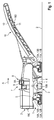
- FIGS. 1 and 2 show in side and top view as an example of a self-propelled construction machine, a road milling machine for milling of road surfaces, which is a front-loading road milling machine.
- the road milling machine can also be a rear-loading road milling machine.
- the construction machine has a machine frame 2 carried by a chassis 1, on which a working device 3 is arranged.
- the working device 3 has a work roll, which is a milling drum.
- a work roll which is a milling drum.
- milling drum 4 is arranged in a Fräswalzengephaseuse 5.
- the milling drum housing 5 is closed by an edge guard 6.
- the milling drum housing 5 is closed by a hold-down device and at the rear side by a scraper, which in Fig. 1 are not recognizable.
- Above the milling drum housing 5 is located on the machine frame of the control station 7 with a control panel 8 for the operator.
- a display unit 9 with a display 9A.
- the milled material to be milled is removed with a transport device 10 that extends far beyond the machine frame 2 in the working direction A.
- the transport device 10 has an elongated arm 11, which is pivotable about an axis extending perpendicularly on the plane of the machine frame to both sides on the machine frame 2 in the working direction in front of the control station 7 is attached.
- the boom 11 is pivotable about an axis parallel to the plane of the machine frame 2 extending axis, so that the boom is moved up and down.
- a conveyor belt 12 for conveying the milled material.
- the construction machine has in the working direction A a front left drive 11A and a front right drive 11B and a rear left drive 12A and a rear right drive 12B, which in the working direction A front, left and right lifting device 13 A, B and a rear, left and right lifting device 14 A, B are assigned, so that the height and inclination of the machine frame 2 relative to the bottom surface B can be changed by retracting or extending the lifting devices.
- the drives of the construction machine can be both chain drives and wheels.
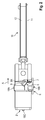
- Fig. 3 shows the essential components of the invention of the construction machine according to the invention in a simplified schematic representation.
- the construction machine has a position detection device 15 for detecting the pivot position of the transport device 10 in the horizontal plane, which may be part of a central control and processing unit 16 of the construction machine.
- the horizontal pivoting position of the transport device 10 may with suitable sensors, for. As angle encoders, distance sensors, etc., are detected or determined from data from the drive means, not shown, for pivoting the transport device, for. B. the stroke position of piston / cylinder assemblies are obtained.
- the position detection device 15 has a computing unit 15B which receives the data of the sensor 15A and configures such that the angle in the horizontal plane between the longitudinal axis of the transport device 10 and the longitudinal axis of the machine frame 2 is determined from the data of, for example, the angle sensor 15 ( pivot position).
- the position detection device 15 can also detect the angle in the vertical plane between the longitudinal axis of the transport device 10 and the longitudinal axis of the machine frame 2 (height).
- the construction machine has an image display device 17 for displaying an image of the surroundings of the construction machine in bird's-eye view, which has a camera system 18 and an image processing system 19.
- the image is displayed on the display 9A of the display unit 9 on the control station 7 in the field of vision of the machine operator.
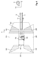
- FIGS. 4 and 5 show a first embodiment and the FIGS. 8 and 9 A second embodiment of the construction machine, which differ only in the number of cameras of the camera system from each other.
- the image display device 17 of the construction machine has a camera system 18 with a plurality of cameras 18A, 18B, 18C, 18D in the first embodiment and 18A, 18B, 18C, 18D ', 18D "in the second embodiment for receiving individual image areas of the surroundings of the construction machine
- the cameras each record a specific image area of the ground surface B.
- the position and size of the image area captured by the camera depends on the arrangement and orientation of the camera and the camera optics, in particular the focal length of the camera lens are arranged and formed such that the image areas captured by the cameras overlap.
- a center-left camera 18A is located midway between the left, front, and rear corner regions of the machine frame 2, and preferably a center-right camera 18B midway between the right, front, and rear corner regions of the machine frame 2, and preferably midway between the rear corner regions of the machine frame, a rear camera 18C. There are no cameras at the front corners of the machine frame.
- each camera 18 A, B, C would receive a substantially rectangular image section of the ground surface B when the Viewing direction of the camera (camera axis) would be orthogonal on the ground surface. Due to the angle of attack, however, a trapezoidal image area of the ground surface is picked up by the camera, ie the area of the terrain outside the trapezoidal area is not detected by the camera.
- the cameras 18 A, B, C on the machine frame 2 are arranged such that the viewing directions 29 of the cameras are directed away from the machine frame 2.
- the camera axes 29 (view directions) of the side cameras 18A and 18B and the rear camera 18C are preferably orthogonal to the long sides of the machine frame 2, with the side cameras 18A, B having a trapezoidal side image area 20A, 20B and the rear camera 18C record a trapezoidal rear image area 20C.
- the camera axes 29 may also be directed forward or backward to capture a larger front or rear terrain area. Then the image areas can be described in a parallel alignment of the machine frame to the ground surface B but not by isosceles trapezoids.
- Fig. 6 shows the viewing direction (camera axis 29) of a camera 18 A, B, C on the machine frame 2, which is directed away from the machine frame 2.
- the camera system 18 of the first embodiment has a front camera 18D disposed on the underside of the boom 11 of the conveyor 10.
- the camera 18D is fixed at a point on the longitudinal axis of the cantilever 11 which lies in an area of the middle third between the two ends of the cantilever.
- the attachment point can also be in the range of the front or rear third of the boom.
- the attachment point should not be in the region of the free end of the boom, since the free end of the boom during operation of the construction machine is temporarily above the loading area of the transport vehicle.
- the front camera 18D is arranged on the underside of the transport device 10 such that the camera axis lies on the longitudinal axis of the transport device and that the viewing direction of the camera is directed in the direction of the machine frame 2.
- the front camera 18D is therefore a backward-looking camera.
- Fig. 7 shows the viewing direction (camera axis 29) of the camera 18D on the transport device 10, which is directed in the direction of the machine frame 2.
- the angle between the camera axis 29 of the front camera 18D and the plane of the machine frame 2 is preferably dimensioned in such a way that the camera receives a working-direction image area which extends into a section below the machine frame 2 ( Fig. 7 ).
- the front camera 18D thus receives a terrain portion 21 which could be seamlessly detected from a bird's-eye view if this area were not covered by the conveyor 10, and a portion 22 of the viewpoint from above a machine frame 2 can not be detected. Since the transport device 10 is adjustable in height, and the angle between the camera axis 29 and the plane of the machine frame 2 changes. The angle of attack of the front camera 18 D is therefore such that in a predetermined position of the transport device 10, the usual operating position corresponds, the two image sections 21, 22 include the desired areas ( Fig. 7 ).
- FIG. 4 shows the construction machine, wherein the longitudinal axis of the transport device 10 is located on the longitudinal axis of the machine frame 2, while Fig. 5 shows the construction machine, wherein the transport device 10 is pivoted to the operating position, for example, to the left side.
- the FIGS. 4 and 5 show that the position of the image area 20D picked up by the front camera 18D also changes with the pivoting position of the transport device.
- the image area 20D of the front camera 18D overlaps with the image area 20A of the lateral, left camera 18A and the image area 20B of the lateral right camera 18B, and the image area 20A of the left camera 18A and the image area 20B of the right camera 18B overlap with the one Image area 20C of the rear camera 18C.
- a rear left overlap area 24A of the image areas 20A, 20C of the left camera 18A and the rear camera 18C and a rear right overlap area 24B of the image areas 20B, 20C of the right camera 18B and the rear camera 18C are provided.
- the image processing system 19 is preferably a data processing unit (CPU) running a data processing program (software).
- the position detecting means 15 is connected to the image processing system 19 via a data line 25 so that the image processing system 19 can receive the position data of the position detecting means.
- the image processing system 19 determines the position of the dotted lines shown in dotted lines of the image area 20D of the front camera 18D, whose position changes during a pivoting movement of the transport device, depending on the pivot position of the transport device 10. Moreover, the image processing system 19 determines the position of the dotted lines of the image areas 20A, 20B, 20C of the left and right cameras 18A, 18B and the rear camera 18C.
- the position of the straight contour lines can be described in a Cartesian X / Y coordinate system lying on the surface of the bottom B by their start and end points. The coordinates of these points are calculated in the image processing system 19 according to an algorithm which takes into account the pivoting position of the transport device.
- the location of the image areas 20 A, B, C, D is known, which are described by the coordinates of the start and end points of the contours, this determines Image processing system 19, the location of the overlapping areas 23A, 23B, 24A, 24B of the adjacent image areas 20A, B, C, D.
- the overlapping areas 23A, 23B, 24A, 24B may be determined, for example, by calculating an intersection of adjacent image areas 20A, B, C, D.
- the image processing system 19 is configured such that image sections are defined in the individual image areas 20A, 20B, 20C, 20D, i. H. matching sections of the recorded image areas 20A, B, C, D of the bottom surface B, which can be combined to form an overall image 27 in bird's eye view without gaps.
- seams stitching
- d. H Border lines between the image sections or cut lines of the image areas. The course of the seams depends on the position of the overlapping trapezoidal image sections.
- the image processing system determines in the X / Y coordinate system the coordinates of the start and end points of the outlines of the front left overlap area 23A, the front right overlap area 23B, the rear left overlap area 24A, and the rear right overlap area 24B.
- the overlap areas are in the FIGS. 4 and 5 represented by hatching.
- the image processing system 19 determines the course of the stitching (stitching), taking into account the following criteria.
- the course of the rear seams in the working direction is determined by the image processing system 19 such that the seams between the left and right image areas 20A, 20B and the rear image area 20C extend within the rear, left and right overlap areas 24A, 24B.
- the image processing system 19 determines the course of the seams such that the seams extend from the back, left and right corners of the machine frame 2 to the intersections of the contours of the adjacent image areas 20A, 20C and 20B, 20C, respectively. This results in a rear left seam 25A and a rear right 25B seam, which in Fig. 5 are shown.
- the image processing system 19 sets a front left seam 25C inside the front left overlap area 23A and a front right seam inside the front right overlap area 23B depending on the pivot position of the conveyor 20 25D stuck.
- the front left seam 25C extends between the intersections S 1 and S 2 of the contours of the front image area 20D and the left image area 20A
- the front right seam 25D extends between the intersections S 3 and S 4 of the contours of the front image area 20D and of the right image area 20B.
- the image section 26C of the front image area 20D is joined to the associated image sections 26A and 26B of the left and right image areas 20A, 20B.
- the outer portions of the front image area 20D are cut along the seams 25C and 25D
- the inner portions of the left and right image areas 20A, 20B are cut along the seams 25C and 25D.
- the location of the beginning and end points of the seams are determined in the X / Y coordinate system by coordinates of the beginning and end points of the seams.
- the image processing system 19 generates a bird's-eye view of the overall image 27 by merging all the image sections. It can be seen that the overall image 27 comprises a portion 27A located on the left longitudinal side of the machine frame 2 and a portion 27B located on the right longitudinal side of the machine frame 2. In addition, the overall image 27 comprises a section 27C lying below the machine frame 2 and a section 20D located in front of the machine frame 2 and a section 20E located behind the machine frame 2.
- the seams for the front image area 20D and the left and right image areas 20A, 20B may also be set such that single or all seams do not run within but along the contour lines or overlapping areas. For example, instead of the left front seam 25C within the Overlap area 25C a between the intersections S 1 and S 2 along the outer contour of the front image area 20D extending seam 25C 'are set. For example, instead of the right front seam 25D within the overlapping area 25D, a seam 25D 'extending between the intersections S 3 and S 4 along the outer contour of the right image area 20B may be defined. It is also possible to specify the seams for the rear image area and the left and right image areas taking into account other criteria.
- FIGS. 8 and 9 show an alternative embodiment, different from that with reference to the FIGS. 4 and 5 in that the camera system 18 has two front cameras 18D 'and 18D "which are arranged on the transport device 10. The corresponding parts are therefore provided with the same reference numerals
- the left front camera 18D' is at the bottom the left longitudinal side and the right front camera 18D "attached to the underside of the right longitudinal side of the cantilever 11 such that the viewing direction of the left camera 18D 'in the left direction and the viewing direction of the right camera 18D" toward the right side of the machine frame 2 is directed when the longitudinal axis of the transport device 10 is located on the longitudinal axis of the machine frame 2 ( Fig. 8 ).
- Both cameras 18D ', 18D are mounted in a portion of the cantilever 11 located in the middle third of the cantilever 16.
- the image areas 20D' and 20D" of the front left and right cameras 18D ', 18D overlap in a front middle overlap area 28
- the image processing system 19 detects the contours of the front left overlap area 23A, the front right overlap area 23B, the rear left overlap area 24A, and the rear right overlap area 24B.
- the rear, left and right seams 24A, 24B are fixed, the seams for the front image areas 20D 'and 20D "of the two cameras 18D', 18D” and the left and right Image areas 20A, 20B are de-rated according to the same criteria determines that the individual image areas can be combined to form a complete overall picture.
- the image processing system 19 can determine the course of the seams and thus the position and size of the image sections which are combined to form the overall image in such a way that the largest possible area of the environment is detected completely with all the cameras.
- the view can be extended to the front at the expense of the view to the rear, or vice versa. But it can also be the view to the left side at the expense of the view to the right side be expanded or vice versa.
- the overall image can then be displayed in full size on the display 9 of the display unit 8. But it is also possible to display only a portion of the overall picture, for example, a rectangular image detail.
Abstract
Die Erfindung betrifft eine selbstfahrende Baumaschine mit einer sich in Arbeitsrichtung A über den Maschinenrahmen 2 hinaus erstreckenden Transporteinrichtung 10, insbesondere Straßenfräsmaschine oder Surface-Miner. Darüber hinaus betrifft die Erfindung ein Verfahren zur Anzeige eines Bildes der Umgebung einer selbstfahrenden Baumaschine. Die eifindungsgemäße Baumaschine verfügt über eine Bildanzeigeeinrichtung 17 zur Anzeige eines Bildes der Umgebung der Baumaschine in der Vogelperspektive, die ein Kamerasystem 18 mit mehreren Kameras 18A,B,C,D zur Aufnahme von einzelnen sich überlappenden Bildbereichen 20A, 20B, 20C, 20D der Baumaschinenumgebung aus unterschiedlichen Bildaufnahmepositionen und ein Bildverarbeitungssystem 19 aufweist. Das Bildverarbeitungssystem 19 ist derart ausgebildet, dass Bildausschnitte der einzelnen Bildbereiche 20A, 20B, 20C, 20D zu einem Gesamtbild 27 in der Vogelperspektive zusammengefügt werden. Das Kamerasystem 18 verfügt über mindestens eine Kamera 18D, 18D', 18D", die derart an der Transporteinrichtung 10 angeordnet ist, dass die Blickrichtung der Kamera in Richtung des Maschinenrahmens 2 gerichtet ist, und mindestens eine weitere Kamera 18A, 18B, 18C, die derart an dem Maschinenrahmen 2 angeordnet ist, dass die Blickrichtung der Kamera von dem Maschinenrahmen 2 weg gerichtet ist. Mit den in und von dem Maschinenrahmen weg gerichteten Kameras erhält der Maschinenführer eine lückenlose Rundumsicht, die den von der Transporteinrichtung abgedeckten Bereich in Arbeitsrichtung vor der Baumaschine einschließt.The invention relates to a self-propelled construction machine with a in the working direction A on the machine frame 2 addition extending transport device 10, in particular road milling machine or surface miner. Moreover, the invention relates to a method for displaying an image of the surroundings of a self-propelled construction machine. The construction machine according to the invention has an image display device 17 for displaying an image of the surroundings of the construction machine in a bird's-eye view, a camera system 18 with a plurality of cameras 18A, B, C, D for receiving individual overlapping image areas 20A, 20B, 20C, 20D of the construction machine environment from different image pickup positions and an image processing system 19. The image processing system 19 is designed such that image sections of the individual image regions 20A, 20B, 20C, 20D are combined to form an overall image 27 in bird's eye view. The camera system 18 has at least one camera 18D, 18D ', 18D ", which is arranged on the transport device 10 such that the viewing direction of the camera is directed in the direction of the machine frame 2, and at least one further camera 18A, 18B, 18C, the is arranged on the machine frame 2 so that the viewing direction of the camera is directed away from the machine frame 2. With the cameras directed in and away from the machine frame, the machine operator obtains a complete all-round view which covers the area covered by the transport device in the working direction in front of the construction machine includes.
Description
Die Erfindung betrifft eine selbstfahrende Baumaschine mit einer sich in Arbeitsrichtung über den Maschinenrahmen hinaus erstreckenden Transporteinrichtung, insbesondere Straßenfräsmaschine oder Surface-Miner, die eine Bildanzeigeeinrichtung zur Anzeige eines Bildes der Umgebung der Baumaschine aufweist. Darüber hinaus betrifft die Erfindung ein Verfahren zur Anzeige eines Bildes der Umgebung einer selbstfahrenden Baumaschine.The invention relates to a self-propelled construction machine having a transport device extending beyond the machine frame in the working direction, in particular a road milling machine or surface miner, which has an image display device for displaying an image of the surroundings of the construction machine. Moreover, the invention relates to a method for displaying an image of the surroundings of a self-propelled construction machine.
Die bekannten Baumaschinen verfügen über einen Maschinenrahmen, der von einem Fahrwerk getragen wird, das vordere und hintere Laufwerke aufweist, und eine am Maschinenrahmen angeordnete Arbeitseinrichtung zum Abtragen des Bodens, beispielsweise zum Abtragen schadhafter Straßenschichten (Straßenfräsmaschine) oder Abbau von Bodenschätzen (Surface-Miner). Die Arbeitseinrichtung kann eine Fräs- und/oder Schneidwalze aufweisen. Den einzelnen Laufwerken der Baumaschine sind Hubeinrichtungen zugeordnet, die jeweils ein- bzw. ausgefahren werden können, so dass der Maschinenrahmen zusammen mit der Arbeitseinrichtung gegenüber der Bodenoberfläche abgesenkt bzw. angehoben oder die Neigung zur Bodenoberfläche verändert werden kann. Das abgetragene Material wird mit einer Transporteinrichtung zu einem Transportfahrzeug gefördert, das der Baumaschine vorausfährt oder folgt. Die Transporteinrichtung weist einen sich über den Maschinenrahmen hinaus erstreckenden Ausleger auf, der am Maschinenrahmen um eine senkrecht zu der Ebene des Maschinenrahmens verlaufende Achse schwenkbar angeordnet ist. Der Ausleger ist auch um eine parallel zu der Ebene des Maschinenrahmens und quer zu der Längsachse der Baumaschine verlaufende Achse schwenkbar. Folglich kann der Ausleger sowohl zu beiden Seiten geschwenkt als auch in der Höhe verstellt werden. Bei Frontlader-Baumaschinen erstreckt sich der Ausleger in Arbeitsrichtung weit über den Maschinenrahmen nach vorne und bei Hecklader-Baumaschinen nach hinten hinaus.The known construction machines have a machine frame, which is supported by a chassis, which has front and rear drives, and arranged on the machine frame working device for removing the soil, for example, for removing defective road layers (road milling machine) or mining of mineral resources (surface miner) , The working device may have a milling and / or cutting roller. The individual drives of the construction machine are associated with lifting devices, which can each be extended or retracted so that the machine frame can be lowered or raised together with the working device relative to the ground surface or the inclination to the ground surface can be changed. The removed material is conveyed by a transport device to a transport vehicle, which precedes or follows the construction machine. The transport device has a boom which extends beyond the machine frame and is pivotably arranged on the machine frame about an axis perpendicular to the plane of the machine frame. The boom is also pivotable about an axis parallel to the plane of the machine frame and transverse to the longitudinal axis of the construction machine. Consequently, the boom can be both swung on both sides and adjusted in height. In the case of front loader construction machines, the boom extends in the working direction far beyond the machine frame to the front and in rear loader construction machines to the rear.
Für den Maschinenführer stellt sich das Problem, dass die Umgebung der Baumaschine vom Fahrstand aus nur beschränkt einsehbar ist. Bei Frontlader- und Hecklader-Baumaschinen kommt erschwerend hinzu, dass die Sicht des Maschinenführers durch die weit ausladende Transporteinrichtung nach vorne bzw. hinten beschränkt wird. Folglich kann der Maschinenführer einer Straßenfräsmaschine Objekte vom Fahrstand aus nicht erkennen, die in seinem Sichtbereich von der Transporteinrichtung verdeckt werden. In Abhängigkeit von der Position des Fahrers auf dem sich über die gesamte Breite der Maschine erstreckenden Fahrstand und dem großen Schwenkbereich der Transporteinrichtung können nicht nur unmittelbar unterhalb, sondern auch neben oder vor und hinter der Transporteinrichtung befindliche Objekte verdeckt sein.For the machine operator, there is the problem that the surroundings of the construction machine can only be viewed from the control station to a limited extent. For front-loader and rear-loader construction machinery is aggravating added that the view of the machine operator is limited by the far-reaching transport forward or backward. Consequently, the operator of a road milling machine can not detect objects from the control station, which are hidden in his field of view of the transport device. Depending on the position of the driver on the extending over the entire width of the machine control station and the large pivoting range of the transport device not only immediately below, but also adjacent or in front of and behind the transport device located objects may be covered.
Wegen der beschränkten Sicht sind Baumaschinen bekannt, die mit einer oder mehreren Kameras ausgestattet sind. Bekannte Straßenfräsmaschinen verfügen beispielsweise über eine Kamera, die ein Bild von einem rückwärtigen Bereich der Baumaschine aufnimmt, das auf einer am Fahrstand angeordneten Anzeigeeinheit angezeigt wird. Dadurch wird für den Maschinenführer das Zurücksetzen der Baumaschine erleichtert.Because of the limited view of construction machines are known that are equipped with one or more cameras. Known road milling machines have, for example, a camera which takes a picture of a rear area of the construction machine, which is displayed on a control unit arranged on the display unit. This makes it easier for the operator to reset the construction machine.
Die
Für Kraftfahrzeuge, insbesondere Personenkraftfahrzeuge, sind Vorrichtungen bekannt, die den Fahrer beim Einparken des Fahrzeugs unterstützen. Derartige Vorrichtungen werden auch als Fahrerassistenzsysteme bezeichnet, die dem Fahrer des Kraftfahrzeuges ein lückenloses Bild der Fahrzeugumgebung aus einem virtuellen Sichtpunkt liefern, der oberhalb des Fahrzeugs liegt. Eine derartige Rundumansicht der Umgebung (surround-view) wird auch als eine Ansicht in der Vogelperspektive (bird-view) bezeichnet.For motor vehicles, in particular passenger vehicles, devices are known which assist the driver when parking the vehicle. Such devices are also referred to as driver assistance systems, which provide the driver of the motor vehicle with a complete picture of the vehicle surroundings from a virtual viewpoint that lies above the vehicle. Such a surround-view of the environment (surround-view) is also referred to as a bird's eye view.
Die
Die
Ein Verfahren zum Zusammenfügen mehrerer Bildaufnahmen zu einem Gesamtbild in der Vogelperspektive ist auch aus der
Die
Obwohl sich im druckschriftlichen Stand der Technik vereinzelte Hinweise auf die Verwendung der bekannten Fahrerassistenzsysteme auch bei Baumaschinen finden lassen, werden die bekannten vorzugsweise für Personen- oder Lastkraftwagen bestimmten Fahrerassistenzsysteme aber den besonderen Anforderungen, die selbstfahrende Baumaschinen mit einer sich weit nach vorne hinaus erstreckenden Transporteinrichtung, insbesondere Straßenfräsmaschine oder Surface-Miner, an Fahrerassistenzsysteme stellen, im Allgemeinen nicht gerecht, da sich diese Baumaschinen von Kraftfahrzeugen insofern grundlegend voneinander unterscheiden, als ein Kraftfahrzeug weder über eine Arbeitseinrichtung zum Abtragen von Bodenmaterial noch über eine Transporteinrichtung verfügt.Although isolated references in the printed prior art to the use of the known driver assistance systems can also be found in construction machines, the known driver assistance systems, which are preferably intended for passenger cars or lorries, but the special requirements, the self-propelled construction machines with a transport device extending far to the front, In particular, road milling machine or surface miner to provide driver assistance systems, generally not fair, since these construction vehicles of motor vehicles fundamentally different insofar as a motor vehicle has neither a working device for removing soil material nor a transport device.
Die bekannten Lösungen für Fahrerassistenzsysteme zur Anzeige eines Bildes der Umgebung eines Fahrzeugs in der Vogelperspektive machen ausschließlich von Kameras Gebrauch, deren Blickrichtung von dem Fahrzeug weg gerichtet ist bzw. von Kameras, deren Blickrichtungen voneinander weg gerichtet sind, d. h. die Systeme sehen keine Kameras vor, die einander zugewandt sind. So hat sich die Meinung festgefahren, die Verlängerungen der Achsen sämtlicher Kameras entgegen der Blickrichtung müssten sich in einem gemeinsamen Zentrum treffen. Die Fachleute waren der Ansicht, dass nicht der Maschinenrahmen, sondern die Umgebung des Fahrzeuges erfasst werden soll, um eine lückenlose Rundumsicht zu ermöglichen. Daher sind bei sämtlichen Fahrzeugen Kameras vorgesehen, die von dem Fahrzeug bzw. von einem gemeinsamen Zentrum wegweisen. Dies gilt auch für die Kameras, die an Anbauteilen des Fahrzeuges, beispielsweise an den Rückspiegeln eines Kraftfahrzeuges, angebracht sind.The known solutions for driver assistance systems for displaying an image of the surroundings of a vehicle in a bird's-eye view only use cameras whose viewing direction is directed away from the vehicle or from cameras whose viewing directions are directed away from one another, ie the systems do not provide cameras. which are facing each other. Thus, the opinion has become deadlocked, the extensions of the axes of all cameras against the line of sight would have to meet in a common center. The experts were of the opinion that not the machine frame, but the environment of the vehicle should be recorded to allow a complete visibility. Therefore, cameras are provided in all vehicles, which point away from the vehicle or from a common center. This also applies to the cameras, which are attached to attachments of the vehicle, for example, to the rear-view mirrors of a motor vehicle.
Der Erfindung liegt die Aufgabe zugrunde, eine selbstfahrende Baumaschine mit einer sich in Längsrichtung der Baumaschine über den Maschinenrahmen nach vorne oder hinten hinaus erstreckenden Transporteinrichtung zum Fördern von abgetragenem Material, insbesondere eine Straßenfräsmaschine oder einen Surface-Miner, zu schaffen, die dem Maschinenführer einen hohen Bedienkomfort bietet. Darüber hinaus ist eine Aufgabe der Erfindung, ein Verfahren zur Verbesserung des Bedienkomforts anzugeben.The invention has for its object to provide a self-propelled construction machine with in the longitudinal direction of the construction machine on the machine frame forward or rear out extending transport device for conveying abraded material, in particular a road milling machine or a surface miner, the machine operator a high Ease of use offers. In addition, it is an object of the invention to provide a method for improving the ease of use.
Die Lösung dieser Aufgaben erfolgt mit den Merkmalen der unabhängigen Patentansprüche. Die abhängigen Ansprüche betreffen vorteilhafte Ausführungsformen der Erfindung.The solution of these objects is achieved with the features of the independent claims. The dependent claims relate to advantageous embodiments of the invention.
Die erfindungsgemäße Baumaschine verfügt über eine Bildanzeigeeinrichtung zur Anzeige eines Bildes der Umgebung der Baumaschine in der Vogelperspektive, die ein Kamerasystem mit mehreren Kameras zur Aufnahme von einzelnen sich überlappenden Bildbereichen der Baumaschinenumgebung aus unterschiedlichen Bildaufnahmepositionen und ein Bildverarbeitungssystem aufweist. Das Bildverarbeitungssystem ist derart ausgebildet, dass Bildausschnitte der einzelnen Bildbereiche zu einem Gesamtbild in der Vogelperspektive zusammengefügt werden.The construction machine according to the invention has an image display device for displaying an image of the surroundings of the construction machine in a bird's-eye view, comprising a camera system with a plurality of cameras for recording individual overlapping image areas of the construction machine environment from different image pickup positions and an image processing system. The image processing system is designed in such a way that image sections of the individual image areas are combined to form an overall bird's-eye view image.
Das Kamerasystem verfügt über mindestens eine Kamera, die derart an der Transporteinrichtung angeordnet ist, dass die Blickrichtung der Kamera im Wesentlichen in Richtung des Maschinenrahmens gerichtet ist, und mindestens eine weitere Kamera, die derart an dem Maschinenrahmen angeordnet ist, dass die Blickrichtung der Kamera im Wesentlichen von dem Maschinenrahmen weg gerichtet ist. Unter einer Kamera, die im Wesentlichen in Richtung des Maschinenrahmens gerichtet ist, wird also eine Kamera verstanden, deren Blickrichtung auf den Maschinenrahmen weist, während unter einer Kamera, die im Wesentlichen von dem Maschinenrahmen weg gerichtet ist, eine Kamera verstanden wird, deren Blickrichtung nicht auf den Maschinenrahmen weist.The camera system has at least one camera which is arranged on the transport device such that the viewing direction of the camera is directed essentially in the direction of the machine frame, and at least one further camera which is arranged on the machine frame such that the viewing direction of the camera in the Essentially away from the machine frame. Under a camera, which is directed substantially in the direction of the machine frame, so a camera is understood, the viewing direction points to the machine frame, while under a camera, which is directed away from the machine frame substantially, a camera is understood, the viewing direction is not points to the machine frame.
Die in Richtung des Maschinenrahmens gerichtete Blickrichtung der mindestens einen an der Transporteinrichtung angeordneten Kamera erlaubt eine Anzeige eines Bildes des gesamten vorderen Bereichs der Baumaschine, was aufgrund der Abdeckung durch die Transporteinrichtung mit einer am Maschinenrahmen angeordneten Kamera, die von dem Maschinenrahmen weg gerichtet ist, nicht möglich wäre. Mit den in Richtung des Maschinenrahmens gerichteten und von dem Maschinenrahmen weg gerichteten Kameras erhält der Maschinenführer eine lückenlose Rundumsicht, die den von der Transporteinrichtung abgedeckten Bereich in Arbeitsrichtung vor oder hinter der Baumaschine einschließt.The viewing direction of the at least one camera arranged on the transport device in the direction of the machine frame permits display of an image of the camera entire front area of the construction machine, which would not be possible due to the cover by the transport device with a machine frame arranged on the camera, which is directed away from the machine frame. With the cameras directed in the direction of the machine frame and directed away from the machine frame, the machine operator obtains a complete all-round view, which encloses the area covered by the transport device in the working direction in front of or behind the construction machine.
Im Gegensatz zu den bekannten Systemen sieht die Erfindung mindestens eine Kamera vor, deren Blickrichtung nicht von dem Maschinenrahmen weg, sondern auf den Maschinenrahmen zu gerichtet ist. Daher geht die Erfindung bei der Lösung des Problems einer eingeschränkten Sicht bei Baumaschinen einen neuen Weg.In contrast to the known systems, the invention provides at least one camera whose viewing direction is not directed away from the machine frame, but rather towards the machine frame. Therefore, the invention goes a long way in solving the problem of limited visibility in construction machinery.
Bei einer bevorzugten Ausführungsform ist die mindestens eine Kamera derart an der Transporteinrichtung angeordnet, dass ein Teil des von der mindestens einen Kamera aufgenommenen Bildbereichs unterhalb des Maschinenrahmens liegt. Folglich erlaubt die mindestens eine Kamera mit der rückwärtigen Blickrichtung nicht nur eine den Abschnitt vor, sondern auch einen den Abschnitt unterhalb des Maschinenrahmens umfassende Rundumsicht. Bei einer Frontlader-Baumaschine liegt der Abschnitt unterhalb des Maschinenrahmens vorzugsweise im Bereich mindestens eines vorderen Laufwerks der Baumaschine, so dass der Maschinenführer auch erkennen kann, wie sich das Laufwerk auf ein Objekt zubewegt, das unmittelbar vor dem Laufwerk liegt. Bei einer Hecklader-Baumaschine ergeben sich analoge Verhältnisse.In a preferred embodiment, the at least one camera is arranged on the transport device such that a part of the image area captured by the at least one camera lies below the machine frame. Consequently, the at least one camera with the rearward viewing direction allows not only an all-round view, but also a 360-degree view encompassing the portion below the machine frame. In a front loader construction machine, the portion below the machine frame is preferably in the area of at least one front drive of the construction machine, so that the operator can also recognize how the drive moves toward an object immediately in front of the drive. In a rear-loader construction machine analogous conditions arise.
Die Transporteinrichtung weist vorzugsweise einen Ausleger auf, an dem ein Förderband angeordnet ist, wobei die mindestens eine an der Transporteinrichtung angeordnete Kamera an der Unterseite des Auslegers angeordnet ist. Die mindestens eine Kamera kann grundsätzlich an einem Befestigungspunkt über die gesamte Länge des Auslegers angeordnet sein. Die Kamera sollte aber während des Verladevorgangs der Baumaschine oberhalb des Bodens, nicht aber oberhalb der Ladefläche des Transportfahrzeuges liegen. Die mindestens eine Kamera kann unter unterschiedlichen Blickwinkeln gegenüber dem Maschinenrahmen und somit gegenüber der Bodenoberfläche angeordnet sein. Von Vorteil ist, wenn die Kamera möglichst weit von der Frontseite der Baumaschine entfernt ist, so dass der von der Kamera aufgenommene Bildbereich möglichst groß ist. Dabei ist auch vorteilhaft, dass mit zunehmender Entfernung der Kamera von der Frontseite der Baumaschine die Höhe der Kamera gegenüber der Bodenoberfläche zunimmt, da die Transporteinrichtung in Arbeitsrichtung nach oben geneigt ist.The transport device preferably has a boom on which a conveyor belt is arranged, wherein the at least one camera arranged on the transport device is arranged on the underside of the delivery arm. The at least one camera can in principle be arranged at an attachment point over the entire length of the jib. However, the camera should be located during the loading process of the construction machine above the ground, but not above the loading area of the transport vehicle. The at least one camera can be arranged at different angles with respect to the machine frame and thus with respect to the ground surface. Advantageous is when the camera is as far away as possible from the front of the construction machine, so that the image area taken by the camera is as large as possible. It is also advantageous that with increasing distance of the camera from the front of the construction machine, the height of the camera relative to the ground surface increases, since the transport device is inclined in the working direction upwards.
Eine Ausführungsform sieht vor, dass das Kamerasystem eine an der Unterseite des Auslegers der Transporteinrichtung angeordnete Kamera aufweist, wobei die Kameraachse in Längsrichtung des Auslegers verläuft, während eine alternative Ausführungsform zwei an der Unterseite des Auslegers angeordnete Kameras vorsieht, deren Kameraachsen schräg zur Längsrichtung des Auslegers verlaufen. Dabei ist die Blickrichtung der einen Kamera in Richtung der einen Seite des Maschinenrahmens und die Blickrichtung der anderen Kamera in Richtung der anderen Seite des Maschinenrahmens gerichtet, wenn der Ausleger nicht auf die eine oder andere Seite geschwenkt ist. Die Ausführungsform mit zwei Kameras hat den Vorteil, dass die Kameras einen kleineren Blickwinkel (Brennweite) haben können, um den gleichen Bildbereich aufnehmen zu können bzw. mit dem gleichen Blickwinkel (Brennweite) ein größerer Bildbereich aufgenommen werden kann.One embodiment provides that the camera system has a camera arranged on the underside of the delivery arm of the transport device, wherein the camera axis extends in the longitudinal direction of the delivery, while an alternative embodiment provides two cameras arranged on the underside of the delivery, whose camera axes are oblique to the longitudinal direction of the delivery run. In this case, the viewing direction of the one camera in the direction of one side of the machine frame and the viewing direction of the other camera in the direction of the other side of the machine frame, when the boom is not pivoted to one side or the other. The embodiment with two cameras has the advantage that the cameras can have a smaller viewing angle (focal length) in order to be able to record the same image area or with the same viewing angle (focal length) a larger image area can be recorded.
Für eine lückenlose Rundumsicht ist im Allgemeinen ausreichend, wenn das Kamerasystem zur Aufnahme eines linken und rechten Bildbereichs eine linke Kamera an der in Arbeitsrichtung linken Längsseite des Maschinenrahmens und eine rechte Kamera an der in Arbeitsrichtung rechten Längsseite des Maschinenrahmens und zur Aufnahme eines hinteren Bildbereichs eine in Arbeitsrichtung hintere Kamera aufweist. An den Längsseiten und/oder der Rückseite der Baumaschine können aber auch mehrerer Kameras vorgesehen sein.For a complete all-round view is generally sufficient when the camera system for receiving a left and right image area a left camera on the left in the machine direction longitudinal side of the machine frame and a right camera on the right in the working direction longitudinal side of the machine frame and for receiving a rear image area in Working direction rear camera has. On the long sides and / or the back of the construction machine but also several cameras can be provided.
Bei einer besonders bevorzugten Ausführungsform sind die linke Kamera und die rechte Kamera und die mindestens eine an der Transporteinrichtung angeordnete Kamera derart an dem Maschinenrahmen und der Transporteinrichtung angeordnet, dass sich der Bildbereich der rechten Kamera und der Bildbereich der linken Kamera mit dem mindestens einen Bildbereich der mindestens einen an der Transporteinrichtung angeordneten Kamera in einem Bereich auf der linken und rechten Längsseite des Maschinenrahmens überlappen. Vorzugsweise überlappen sich auch die Bildbereiche der linken und rechten Kamera mit dem Bildbereich der rückwärtigen Kamera.In a particularly preferred embodiment, the left camera and the right camera and the at least one arranged on the transport device camera are arranged on the machine frame and the transport device that the image area of the right camera and the image area of the left camera with the at least one image area of at least one camera arranged on the transport device in an area on the left and right longitudinal sides of the camera Machine frame overlap. Preferably, the image areas of the left and right camera overlap with the image area of the rear camera.
Das Bildverarbeitungssystem ist vorzugsweise derart konfiguriert, dass in dem Bildbereich der linken Kamera, dem Bildbereich der rechten Kamera und dem Bildbereich der mindestens einen an der Transporteinrichtung angeordneten Kamera Bildausschnitte festgelegt werden, die zu einem Gesamtbild in der Vogelperspektive zusammengefügt werden, das einen auf der linken und rechten Längsseite des Maschinenrahmens liegenden Abschnitt, einen unterhalb des Maschinenrahmens liegenden Abschnitt und einen vor dem Maschinenrahmen liegenden Abschnitt umfasst. Damit ist für den Maschinenführer eine lückenlose Rundumsicht gegeben.The image processing system is preferably configured in such a way that in the image area of the left camera, the image area of the right camera and the image area of the at least one camera arranged on the transport device image sections are defined which are combined to form an overall bird's-eye view, one on the left and a right longitudinal side of the machine frame section, a section lying below the machine frame and a section lying in front of the machine frame. This provides the machine operator with a complete all-round view.
Zur Ausrichtung der Transporteinrichtung auf die Ladefläche des Transportfahrzeugs ist die Transporteinrichtung einer Baumaschine an dem Maschinenrahmen im Allgemeinen um eine senkrecht auf der Ebene des Maschinenrahmens verlaufende Achse schwenkbar angeordnet. Wenn die Transporteinrichtung auf die eine oder andere Seite geschwenkt wird, ändert sich der von der mindestens einen an der Transporteinrichtung angeordneten Kamera aufgenommene Bildbereich.For aligning the transport device on the loading surface of the transport vehicle, the transport device of a construction machine on the machine frame is generally arranged pivotable about an axis perpendicular to the plane of the machine frame axis. When the transport device is pivoted to one side or the other, the image area recorded by the at least one camera arranged on the transport device changes.
Eine weitere besonders bevorzugte Ausführungsform weist daher eine die Schwenkstellung der Transporteinrichtung erfassende Lageerfassungs-Einrichtung auf, wobei das Bildverarbeitungssystem derart konfiguriert ist, dass der Verlauf der Nähte zwischen den Bildausschnitten in Abhängigkeit von der Schwenkstellung der Transporteinrichtung festgelegt wird.A further particularly preferred embodiment therefore has a position detection device which detects the pivoting position of the transport device, the image processing system being configured such that the course of the seams between the image sections is determined as a function of the pivoting position of the transport device.
Die Festlegung des Verlaufs der Nähte in Abhängigkeit von der Schwenkstellung der Transporteinrichtung erlaubt ein relativ einfaches Zusammenfügen der einzelnen Bilder mit einem verhältnismäßig geringen Rechenaufwand, so dass die für die Anzeige des Gesamtbildes erforderlichen Bilddaten in Echtzeit generiert werden können.
Die Lageerfassungs-Einrichtung ist vorzugsweise derart konfiguriert, dass die Schwenkstellung beschreibende Positions-Daten erzeugt werden. Dabei ist unerheblich, wie die Positions-Daten ermittelt werden. Die Schwenkstellung kann beispielsweise mit Winkelgebern, Abstandssensoren oder dergleichen erfasst werden.The determination of the course of the seams as a function of the pivot position of the transport device allows a relatively simple assembly of the individual images with a relatively low computational effort, so that the image data required for the display of the overall image can be generated in real time.
The attitude detection means is preferably configured to generate position data describing the pivot position. It is irrelevant How the position data is determined. The pivot position can be detected for example with angle encoders, distance sensors or the like.
Bei einer Schwenkbewegung der Transporteinrichtung verändert sich der von der Kamera erfasste Bildbereich, wobei sich die Umrisslinie des Bildbereichs verschiebt. In Abhängigkeit von der Schwenkstellung der Transporteinrichtung ergeben sich unterschiedliche Überlappungsbereiche. Die räumliche Lage und Ausdehnung der Überlappungsbereiche bestimmt die Abmessungen der auszuwählenden Bildausschnitte, die zu dem Gesamtbild in der Vogelperspektive zusammengefügt werden. Dadurch wird auch der Verlauf der Nähte zwischen den Bildausschnitten bestimmt.During a pivoting movement of the transport device, the image area captured by the camera changes, with the outline of the image area shifting. Depending on the pivot position of the transport device, different overlapping areas result. The spatial location and extent of the overlapping areas determines the dimensions of the image sections to be selected, which are combined to form the overall image in bird's-eye view. This also determines the course of the seams between the image sections.
Das Bildverarbeitungssystem ist vorzugsweise derart konfiguriert, dass auf der Basis der Positions-Daten der Verlauf der Nähte zwischen den Bildausschnitten derart festgelegt wird, dass die Nähte innerhalb der Überlappungsbereiche des linken und rechten Bildbereichs mit dem vorderen Bildbereich und innerhalb der Überlappungsbereiche des linken und rechten Bildbereichs mit dem hinteren Bildbereich liegen. Dadurch können Objekte im Bereich der Nahtstellen, die aufgrund von Abbildungsfehlern möglicherweise doppelt oder überhaupt nicht wiedergegeben werden, besser erfasst werden.The image processing system is preferably configured to determine, based on the positional data, the course of the seams between the image sections such that the seams within the overlapping areas of the left and right image areas coincide with the front image area and within the overlap areas of the left and right image areas lie with the rear image area. As a result, objects in the region of the seams, which may be reproduced twice or not at all due to aberrations, can be better detected.
In diesem Zusammenhang wird unter dem Verlauf der Naht die räumliche Anordnung der Naht, d. h. die Linie verstanden, entlang der die Naht verläuft. Die Festlegung des Verlaufs der Nähte kann mit den bekannten Algorithmen erfolgen, die eine Verschiebung der Nahtlinie in Abhängigkeit von der Schwenkstellung der Transporteinrichtung berechnet.In this context, under the course of the seam, the spatial arrangement of the seam, i. H. understood the line along which the seam runs. The determination of the course of the seams can be done with the known algorithms, which calculates a shift of the seam line in dependence on the pivot position of the transport device.
Die Transporteinrichtung ist im Allgemeinen auch um eine parallel zu der Ebene des Maschinenrahmens und quer zu der Längsachse der Baumaschine verlaufende Achse schwenkbar an dem Maschinenrahmen angeordnet. Dadurch kann die Transporteinrichtung auch in der Höhe verstellt werden. Mit einer Höhenverstellung der Transporteinrichtung ändert sich auch der Blickwinkel der mindestens einen Kamera an der Transporteinrichtung, wodurch sich die Umrisslinie des aufgenommenen Bildbereichs verschiebt. Die Lageerfassungs-Einrichtung kann derart konfiguriert sein, dass nicht nur die Schwenkstellung, sondern auch den Anstellwinkel der Transporteinrichtung gegenüber der Ebene des Maschinenrahmens beschreibende Positions-Daten erzeugt werden, wobei das Bildverarbeitungssystem derart konfiguriert ist, dass der Verlauf der Nähte zwischen den Bildausschnitten auch in Abhängigkeit von dem Anstellwinkel der Transporteinrichtung festgelegt wird.The transport device is also generally pivotally mounted on the machine frame about an axis parallel to the plane of the machine frame and transverse to the longitudinal axis of the construction machine. As a result, the transport device can also be adjusted in height. With a height adjustment of the transport device, the viewing angle of the at least one camera on the transport device also changes, as a result of which the outline of the recorded image area shifts. The attitude detection device may be configured such that not only the pivotal position but also the angle of attack of the transporting device are opposite position data describing the plane of the machine frame, the image processing system being configured such that the course of the seams between the image sections is also determined as a function of the angle of attack of the transport device.
Eine Schrägstellung der Kameraachsen zur Bodenoberfläche führt zwangsläufig zu Verzerrungen bei der Darstellung des Kamerabildes in der rechteckförmigen Bildebene. Diese Verzerrungen können aber mit den bekannten Verfahren der Bildverarbeitung zumindest teilweise ausgeglichen werden.An inclination of the camera axes to the ground surface inevitably leads to distortions in the representation of the camera image in the rectangular image plane. However, these distortions can be at least partially compensated with the known methods of image processing.
Im Folgenden werden Ausführungsbeispiele der Erfindung unter Bezugnahme auf die Figuren im Einzelnen erläutert.In the following, embodiments of the invention will be explained in detail with reference to the figures.
Es zeigen:
-
Fig. 1 ein Ausführungsbeispiel einer selbstfahrenden Baumaschine in der Seitenansicht, -
Fig. 2 die Baumaschine vonFig. 1 in der Draufsicht, -
Fig. 3 die für die Erfindung wesentlichen Komponenten der Bildanzeigeeinrichtung der erfindungsgemäßen Baumaschine in vereinfachter schematischer Darstellung, -
Fig. 4 eine Ausführungsform der Baumaschine mit einer an der Transporteinrichtung angeordneten Kamera, deren Kameraachse in Längsrichtung der Transporteinrichtung verläuft, wobei die Längsachse der Transporteinrichtung auf der Längsachse des Maschinenrahmens liegt, -
Fig. 5 die Baumaschine vonFig. 4 , wobei die Transporteinrichtung zu einer Seite des Maschinenrahmens geschwenkt ist, -
Fig. 6 der Blickwinkel einer an dem Maschinenrahmen angeordneten Kamera, -
Fig. 7 der Blickwinkel einer an der Transporteinrichtung angeordneten Kamera, -
Fig. 8 eine Ausführungsform der Baumaschine mit zwei an der Transporteinrichtung angeordneten Kameras, deren Kameraaschen schräg zu der Längsachse der Transporteinrichtung, wobei die Längsachse der Transporteinrichtung auf der Längsachse des Maschinenrahmens liegt, und -
Fig. 9 die Baumaschine vonFig.8 , wobei die Transporteinrichtung zu einer Seite des Maschinenrahmens geschwenkt ist.
-
Fig. 1 an embodiment of a self-propelled construction machine in side view, -
Fig. 2 the construction machine ofFig. 1 in the plan view, -
Fig. 3 the essential components of the image display device of the construction machine according to the invention in a simplified schematic representation, -
Fig. 4 an embodiment of the construction machine with a camera arranged on the transport device, whose camera axis extends in the longitudinal direction of the transport device, wherein the longitudinal axis of the transport device lies on the longitudinal axis of the machine frame, -
Fig. 5 the construction machine ofFig. 4 wherein the transport device is pivoted to one side of the machine frame, -
Fig. 6 the viewing angle of a camera arranged on the machine frame, -
Fig. 7 the angle of view of a camera arranged on the transport device, -
Fig. 8 an embodiment of the construction machine with two arranged on the transport device cameras, the camera ashes obliquely to the longitudinal axis of the transport device, wherein the longitudinal axis of the transport device lies on the longitudinal axis of the machine frame, and -
Fig. 9 the construction machine ofFigure 8 , wherein the transport device is pivoted to one side of the machine frame.
Die
Die Baumaschine verfügt über einen von einem Fahrwerk 1 getragenen Maschinenrahmen 2, an dem eine Arbeitseinrichtung 3 angeordnet ist. Die Arbeitseinrichtung 3 weist eine Arbeitswalze auf, bei der es sich um eine Fräswalze handelt. Die in
Die Baumaschine weist in Arbeitsrichtung A ein vorderes linkes Laufwerk 11A und ein vorderes rechtes Laufwerk 11B und ein hinteres linkes Laufwerk 12A und ein hinteres rechtes Laufwerk 12B auf, denen eine in Arbeitsrichtung A vordere, linke und rechte Hubeinrichtung 13 A,B und eine hintere, linke und rechte Hubeinrichtung 14 A,B zugeordnet sind, so dass durch Einfahren bzw. Ausfahren der Hubeinrichtungen die Höhe und Neigung des Maschinenrahmens 2 gegenüber der Bodenoberfläche B verändert werden kann. Die Laufwerke der Baumaschine können sowohl Kettenlaufwerke als auch Räder sein.The construction machine has in the working direction A a front
Die Lageerfassungs-Einrichtung 15 weist eine die Daten des Sensors 15A empfangende Recheneinheit 15B auf, die derart konfiguriert, dass aus den Daten beispielsweise des Winkelgebers 15A der Winkel in der horizontalen Ebene zwischen der Längsachse der Transporteinrichtung 10 und der Längsachse des Maschinenrahmens 2 bestimmt wird (Schwenkstellung). Die Lageerfassungs-Einrichtung 15 kann auch den Winkel in der vertikalen Ebene zwischen der Längsachse der Transporteinrichtung 10 und der Längsachse des Maschinenrahmens 2 erfassen (Höhe).The
Darüber hinaus verfügt die Baumaschine über eine Bildanzeigeeinrichtung 17 zur Anzeige eines Bildes der Umgebung der Baumaschine in der Vogelperspektive, die ein Kamerasystem 18 und ein Bildverarbeitungssystem 19 aufweist. Die Anzeige des Bildes erfolgt auf dem Display 9A der Anzeigeeinheit 9 am Fahrstand 7 im Sichtfeld des Maschinenführers.In addition, the construction machine has an
Nachfolgend werden Aufbau und Funktion der Bildanzeigeeinrichtung 17 im Einzelnen beschrieben. Die
Die Bildanzeigeeinrichtung 17 der Baumaschine verfügt über ein Kamerasystem 18 mit mehreren Kamers 18A, 18B, 18C, 18D bei dem ersten Ausführungsbeispiel bzw. 18A, 18B, 18C, 18D', 18D" bei dem zweiten Ausführungsbeispiel zur Aufnahme von einzelnen Bildbereichen der Umgebung der Baumaschine aus unterschiedlichen Bildaufnahmepositionen. Die Kameras nehmen jeweils einen bestimmten Bildbereich der Bodenoberfläche B auf. Die Lage und Größe des von der Kamera aufgenommen Bildbereiches ist von der Anordnung und Ausrichtung der Kamera und der Kameraoptik, insbesondere der Brennweite des Objektives der Kamera, abhängig. Die Kameras sind derart angeordnet und ausgebildet, dass sich die von den Kameras aufgenommen Bildbereiche überlappen.The
Bei dem vorliegenden Ausführungsbeispielen befinden sich vorzugsweise mittig zwischen den linken, vorderen und hinteren Eckbereichen des Maschinenrahmens 2 eine seitliche linke Kamera 18A und vorzugsweise mittig zwischen den rechten, vorderen und hinteren Eckbereichen des Maschinenrahmens 2 eine seitliche rechte Kamera 18B und vorzugsweise mittig zwischen den hinteren Eckbereichen des Maschinenrahmens eine hintere Kamera 18C. An den vorderen Eckbereichen des Maschinenrahmens befinden sich keine Kameras.In the present embodiments, preferably a center-left
Es wird angenommen, dass jede Kamera 18 A, B, C einen im Wesentlichen rechteckförmigen Bildausschnitt der Bodenoberfläche B aufnehmen würde, wenn die Blickrichtung der Kamera (Kameraachse) orthogonal auf der Bodenoberfläche stünde. Aufgrund des Anstellwinkels wird von der Kamera aber ein trapezförmiger Bildbereich der Bodenoberfläche aufgenommen, d. h. der außerhalb des trapezförmigen Bereichs liegende Bereich des Geländes wird von der Kamera nicht erfasst.It is assumed that each
Die Kameras 18 A, B, C an dem Maschinenrahmen 2 sind derart angeordnet, dass die Blickrichtungen 29 der Kameras von dem Maschinenrahmen 2 weg gerichtet sind. Die Kameraachsen 29 (Blickrichtungen) der seitlichen Kameras 18A und 18B und der hinteren Kamera 18C stehen vorzugsweise orthogonal zu den Längsseiten bzw. der Schmalseite des Maschinenrahmens 2, wobei die seitlichen Kameras 18A,B einen trapezförmigen, seitlichen Bildbereich 20A, 20B und die hintere Kamera 18C einen trapezförmigen, hinteren Bildbereich 20C aufnehmen. Die Kameraachsen 29 können aber auch nach vorne oder hinten gerichtet sein, um einen größeren vorderen bzw. hinteren Geländebereich zu erfassen. Dann können die Bildbereiche bei einer parallelen Ausrichtung des Maschinenrahmens zur Bodenoberfläche B aber nicht durch gleichschenklige Trapeze beschrieben werden.
Anstelle von zwei Kameras an den vorderen Eckbereichen des Maschinenrahmens weist das Kamerasystem 18 des ersten Ausführungsbeispiels eine vordere Kamera 18D auf, die an der Unterseite des Auslegers 11 der Transporteinrichtung 10 angeordnet ist. Die Kamera 18D ist an einem Punkt auf der Längsachse des Auslegers 11 befestigt, der in einem Bereich des mittleren Drittels zwischen den beiden Enden des Auslegers liegt. Der Befestigungspunkt kann aber auch im Bereich des vorderen oder hinteren Drittels des Auslegers liegen. Allerdings sollte der Befestigungspunkt nicht im Bereich des freien Endes des Auslegers liegen, da sich das freie Ende des Auslegers während des Betriebs der Baumaschine zeitweise über der Ladefläche des Transportfahrzeugs befindet. Bei einer Befestigung der Kamera am freien Ende des Auslegers ist aber nur während des Verladevorgangs mit einer zeitweise eingeschränkten Sicht zu rechnen, nicht aber während des Umsetzens der Baumaschine.Instead of two cameras at the front corners of the machine frame, the
Die vordere Kamera 18D ist derart an der Unterseite der Transporteinrichtung 10 angeordnet, dass die Kameraachse auf der Längsachse der Transporteinrichtung liegt und dass die Blickrichtung der Kamera in Richtung des Maschinenrahmens 2 gerichtet ist. Die vordere Kamera 18D ist daher eine rückwärts blickende Kamera.
Der Winkel zwischen der Kameraachse 29 der vorderen Kamera 18D und der Ebene des Maschinenrahmens 2ist vorzugsweise derart bemessen, dass die Kamera einen in Arbeitsrichtung vorderen Bildbereich aufnimmt, der sich bis in einen Abschnitt unterhalb des Maschinenrahmens 2 erstreckt (
Der Bildbereich 20D der vorderen Kamera 18D überlappt sich mit dem Bildbereich 20A der seitlichen, linken Kamera 18A und dem Bildbereich 20B der seitlichen, rechten Kamera 18B, und der Bildbereich 20A der linken Kamera 18A und der Bildbereich 20B der rechten Kamera 18B überlappt sich mit dem Bildbereich 20C der hinteren Kamera 18C. Es ergeben sich ein vorderer, linker Überlappungsbereich 23A der Bildbereiche 20A, 20D der linken Kamera 18A und der vorderen Kamera 18D und ein vorderer rechter Überlappungsbereich 23B der Bildbereiche 20B, 20D der rechten Kamera 18D und der vorderen Kamera 18D. Des Weiteren ergeben sich ein hinterer linker Überlappungsbereich 24A der Bildbereiche 20A, 20C der linken Kamera 18A und der hinteren Kamera 18C und ein hinterer rechter Überlappungsbereich 24B der Bildbereiche 20B, 20C der rechten Kamera 18B und der hinteren Kamera 18C.The
Das Bildverarbeitungssystem 19 ist vorzugsweise eine Datenverarbeitungseinheit (CPU), auf der ein Datenverarbeitungsprogramm (Software) läuft. Die Lageerfassungs-Einrichtung 15 ist mit dem Bildverarbeitungssystem 19 über eine Datenleitung 25 verbunden, so dass das Bildverarbeitungssystem 19 die Positions-Daten der Lageerfassungs-Einrichtung empfangen kann.The
Zur Vereinfachung wird angenommen, dass sich der Maschinenrahmen 2 in einer zu der Oberfläche des Bodens parallelen Ausrichtung befindet bzw. die Neigung des Maschinenrahmens gegenüber der Geländeoberfläche zu vernachlässigen ist.For simplicity, it is assumed that the
Das Bildverarbeitungssystem 19 bestimmt in Abhängigkeit von der Schwenkstellung der Transporteinrichtung 10 die Lage der in gepunkteten Linien dargestellten Umrisslinien des Bildbereichs 20D der vorderen Kamera 18D, dessen Lage sich bei einer Schwenkbewegung der Transporteinrichtung ändert. Darüber hinaus bestimmt das Bildverarbeitungssystem 19 die Lage der in gepunkteten Linien dargestellten Umrisslinien der Bildbereiche 20A, 20B, 20C der linken und rechten Kamera 18A, 18B und der hinteren Kamera 18C. Die Lage der geraden Umrisslinien kann in einem kartesischen X/Y-Koordinatensystem, das auf der Oberfläche des Bodens B liegt, durch deren Anfangs- und Endpunkte beschrieben werden. Die Koordinaten dieser Punkte werden in dem Bildverarbeitungssystem 19 nach einem Algorithmus berechnet, der die Schwenkstellung der Transporteinrichtung berücksichtigt.The
Nachdem die Lage der Bildbereiche 20 A,B,C,D bekannt ist, die durch die Koordinaten der Anfangs- und Endpunkte der Umrisslinien beschrieben werden, bestimmt das Bildverarbeitungssystem 19 die Lage der Überlappungsbereiche 23A, 23B, 24A, 24B der einander angrenzenden Bildbereiche 20A,B,C,D. Die Überlappungsbereiche 23A, 23B, 24A, 24B können beispielsweise durch Berechnung einer Schnittmenge benachbarter Bildbereiche 20A,B,C,D bestimmt werden.After the location of the
Das Bildverarbeitungssystem 19 ist derart konfiguriert, dass in den einzelnen Bildbereichen 20A, 20B, 20C, 20D Bildausschnitte festgelegt werden, d. h. passende Ausschnitte aus den aufgenommenen Bildbereichen 20A,B,C,D der Bodenoberfläche B, die sich zu einem Gesamtbild 27 in der Vogelperspektive lückenlos zusammenfügen lassen. Beim Zusammenfügen der Bildausschnitte ergeben sich Nähte (Stitching), d. h. Grenzlinien zwischen den Bildausschnitten bzw. Schnittlinien der Bildbereiche. Der Verlauf der Nähte ist von der Lage der sich überlappenden trapezförmigen Bildausschnitte abhängig.The
Das Bildverarbeitungssystem bestimmt in dem X/Y-Koordinatensystem die Koordinaten der Anfangs- und Endpunkte der Umrisslinien des vorderen linken Überlappungsbereichs 23A, des vorderen rechten Überlappungsbereichs 23B, des hinteren linken Überlappungsbereichs 24A und des hinteren rechten Überlappungsbereichs 24B. Die Überlappungsbereiche sind in den
Der Verlauf der in Arbeitsrichtung hinteren Nähte wird von dem Bildverarbeitungssystem 19 derart bestimmt, dass die Nähte zwischen den linken und rechten Bildbereichen 20A , 20B und dem hinteren Bildbereich 20C innerhalb der hinteren, linken und rechten Überlappungsbereiche 24A, 24B verlaufen. Das Bildverarbeitungssystem 19 legt den Verlauf der Nähte derart fest, dass die Nähte sich von dem hinteren, linken und rechten Eckpunkten des Maschinenrahmens 2 bis zu den Schnittpunkten der Umrisslinien der angrenzenden Bildbereiche 20A, 20C bzw. 20B, 20C erstrecken. Es ergeben sich eine hintere linke Naht 25A und eine hintere rechte 25B Naht, die in
Für den vorderen Bildbereich 20D und die linken und rechten Bildbereiche 20A, 20B legt das Bildverarbeitungssystem 19 in Abhängigkeit von der Schwenkstellung der Transporteinrichtung 20 eine innerhalb des vorderen linken Überlappungsbereichs 23A verlaufende vordere linke Naht 25C und eine innerhalb des vorderen rechten Überlappungsbereichs 23B verlaufende vordere rechte Naht 25D fest.For the
Die vordere linke Naht 25C erstreckt sich zwischen den Schnittpunkten S1 und S2 der Umrisslinien des vorderen Bildbereichs 20D und des linken Bildbereichs 20A, und die vordere rechte Naht 25D erstreckt sich zwischen den Schnittpunkten S3 und S4 der Umrisslinien des vorderen Bildbereichs 20D und des rechten Bildbereichs 20B. Zwischen den beiden Nähte 25C und 25D liegt der Bildausschnitt 26C des vorderen Bildbereichs 20D, der mit den zugehörigen Bildausschnitten 26A und 26B des linken und rechten Bildbereichs 20A, 20B zusammengefügt wird. Hierzu werden die außen liegenden Abschnitte des vorderen Bildbereichs 20D entlang der Nähte 25C und 25D abgeschnitten und die innen liegenden Abschnitte des linken und rechten Bildbereiche 20A, 20B werden entlang der Nähte 25C und 25D abgeschnitten.The front
Die Lage der Anfangs- und Endpunkte der Nähte werden in dem X/Y-Koordinatensystem durch Koordinaten der Anfangs- und Endpunkte der Nähte festgelegt.The location of the beginning and end points of the seams are determined in the X / Y coordinate system by coordinates of the beginning and end points of the seams.
Das Bildverarbeitungssystem 19 erzeugt ein Gesamtbild 27 in der Vogelperspektive durch Zusammenfügen sämtlicher Bildausschnitte. Es zeigt sich, dass das Gesamtbild 27 einen auf der linken Längsseite des Maschinenrahmens 2 liegenden Abschnitt 27A und einen auf der rechten Längsseite des Maschinenrahmens 2 liegenden Abschnitt 27B umfasst. Darüber hinaus umfasst das Gesamtbild 27 einen unterhalb des Maschinenrahmens 2 liegenden Abschnitt 27C und einen vor dem Maschinenrahmen 2 liegenden Abschnitt 20D und einen hinter dem Maschinenrahmen 2 liegenden Abschnitt 20E.The
Die Nähte für den vorderen Bildbereich 20D und die linken und rechten Bildbereiche 20A, 20B können auch derart festgelegt werden, dass einzelne oder sämtliche Nähte nicht innerhalb, sondern entlang der Umrisslinien oder Überlappungsbereiche verlaufen. Beispielsweise kann anstelle der linken vorderen Naht 25C innerhalb des Überlappungsbereichs 25C eine zwischen den Schnittpunkten S1 und S2 entlang der äußeren Umrisslinie des vorderen Bildbereichs 20D verlaufende Naht 25C'festgelegt werden. Anstelle der rechten vorderen Naht 25D innerhalb des Überlappungsbereichs 25D kann beispielsweise eine zwischen den Schnittpunkten S3 und S4 entlang der äußeren Umrisslinie des rechten Bildbereichs 20B verlaufende Naht 25D' festgelegt werden. Es ist auch möglich die Nähte für den hinteren Bildbereich und die linken und rechten Bildbereiche unter Berücksichtigung von anderen Kriterien festzulegen.The seams for the
Die
Das Bildverarbeitungssystem 19 kann den Verlauf der Nähte und somit Lage und Größe der Bildausschnitte, die zu dem Gesamtbild zusammengefügt werden, derart festlegen, dass ein möglichst großer Bereich der Umgebung mit sämtlichen Kameras lückenlos erfasst wird. Beispielsweise kann die Sicht nach vorne auf Kosten der Sicht nach hinten erweitert werden oder umgekehrt. Es kann aber auch die Sicht zur linken Seite auf Kosten der Sicht zur rechten Seite erweitert werden oder umgekehrt.The
Das Gesamtbild kann dann auf dem Display 9 der Anzeigeeinheit 8 in der vollen Größe angezeigt werden. Es ist aber auch möglich, nur einen Ausschnitt des Gesamtbildes, beispielsweise einen rechteckförmiger Bildausschnitt anzuzeigen.The overall image can then be displayed in full size on the
Claims (18)
einem Maschinenrahmen (2), der von einem Fahrwerk (1) getragen wird, das vordere und hintere Laufwerke (11A,B; 12A,B) aufweist,
einer am Maschinenrahmen (2) angeordneten Arbeitseinrichtung (3) zum Abtragen von Bodenmaterial,
einer in Arbeitsrichtung (A) sich nach vorne oder nach hinten über den Maschinenrahmen (2) hinaus erstreckenden Transporteinrichtung (10) zum Fördern von abgetragenem Material und
einer Bildanzeigeeimichtung (17) zur Anzeige eines Bildes der Umgebung der Baumaschine,
dadurch gekennzeichnet, dass
die Bildanzeigeeinrichtung (17) als eine Bildanzeigeeinrichtung zur Anzeige eines Bildes der Umgebung der Baumaschine in der Vogelperspektive ausgebildet ist, die ein Kamerasystem (18) mit mehreren Kameras (18A, 18B, 18C, 18D) zur Aufnahme von einzelnen sich überlappenden Bildbereichen (20A, 20B, 20C, 20D) der Umgebung der Baumaschine und ein Bildverarbeitungssystem (19) aufweist, das derart konfiguriert ist, dass Bildausschnitte der einzelnen Bildbereiche (20A, 20B, 20C, 20D) zu einem Gesamtbild (27) in der Vogelperspektive zusammengefügt werden, wobei
das Kamerasystem (18) mindestens eine an der Transporteinrichtung (10) angeordnete Kamera (18D; 18D', 18D") aufweist, die derart an der Transporteinrichtung (10) angeordnet ist, dass die Blickrichtung der Kamera im Wesentlichen in Richtung des Maschinenrahmens (2) gerichtet ist, und
das Kamerasystem (18) mindestens eine an dem Maschinenrahmen (2) angeordnete Kamera (18A, 18B, 18C) aufweist, die derart an dem Maschinenrahmen (2) angeordnet ist, dass die Blickrichtung der Kamera im Wesentlichen von dem Maschinenrahmen (2) weg gerichtet ist.Self-propelled construction machine with
a machine frame (2) supported by a chassis (1) having front and rear drives (11A, B; 12A, B),
a working device (3) arranged on the machine frame (2) for removing soil material,
an in the working direction (A) extending forward or back beyond the machine frame (2) addition transport means (10) for conveying abraded material and
an image display device (17) for displaying an image of the surroundings of the construction machine,
characterized in that
the image display device (17) is designed as an image display device for displaying an image of the surroundings of the construction machine in bird's eye view, comprising a camera system (18) with a plurality of cameras (18A, 18B, 18C, 18D) for recording individual overlapping image regions (20A, 20B, 20C, 20D) of the environment of the construction machine and an image processing system (19) configured to combine image sections of the individual image areas (20A, 20B, 20C, 20D) to form an overall bird's eye view (27)
the camera system (18) has at least one camera (18D, 18D ', 18D ") arranged on the transport device (10), which is arranged on the transport device (10) such that the viewing direction of the camera in the Directed substantially in the direction of the machine frame (2), and
the camera system (18) has at least one camera (18A, 18B, 18C) arranged on the machine frame (2), which is arranged on the machine frame (2) such that the viewing direction of the camera is directed substantially away from the machine frame (2) is.
einen Maschinenrahmen (2), der von einem Fahrwerk (1) getragen wird, das vordere und hintere Laufwerke (11A,B; 12A,B) aufweist,
eine am Maschinenrahmen (2) angeordnete Arbeitseinrichtung (3) zum Abtragen von Bodenmaterial,
eine in Arbeitsrichtung (A) sich über den Maschinenrahmen (2) hinaus erstreckende Transporteinrichtung (10) zum Fördern von abgetragenem Material, dadurch gekennzeichnet, dass
mit mehreren Kameras (18A, 18B, 18C, 18D) einzelne sich überlappende Bildbereiche (20A, 20B, 20C, 20D) der Umgebung der Baumaschine aufgenommen werden, und Bildausschnitte der einzelnen Bildbereiche (20A, 20B, 20C, 20D) zu einem Gesamtbild (27) in der Vogelperspektive zusammengefügt werden,
mindestens eine Kamera (18D; 18D', 18D") an der Transporteinrichtung (10) angeordnet wird, und die Blickrichtung der an der Transporteinrichtung (10) angeordneten Kamera in Richtung des Maschinenrahmens (2) gerichtet wird, und
mindestens eine Kamera (18A, 18B, 18C) an dem Maschinenrahmen (2) angeordnet wird, und die Blickrichtung der an dem Maschinenrahmen (2) angeordneten Kamera von dem Maschinenrahmen (2) weg gerichtet wird.A method of displaying an image of the environment of a self-propelled construction machine comprising
a machine frame (2) supported by a chassis (1) having front and rear drives (11A, B; 12A, B),
a working device (3) arranged on the machine frame (2) for removing soil material,
an in the working direction (A) beyond the machine frame (2) also extending transport means (10) for conveying abraded material, characterized in that
with a plurality of cameras (18A, 18B, 18C, 18D), individual overlapping image areas (20A, 20B, 20C, 20D) of the surroundings of the construction machine are recorded, and image sections of the individual image areas (20A, 20B, 20C, 20D) into an overall image (FIG. 27) are assembled in bird's-eye view,
at least one camera (18D; 18D ', 18D ") is arranged on the transport device (10), and the viewing direction of the camera arranged on the transport device (10) is directed in the direction of the machine frame (2), and
at least one camera (18A, 18B, 18C) is placed on the machine frame (2) and the viewing direction of the camera (2) is directed away from the machine frame (2).
Applications Claiming Priority (1)
| Application Number | Priority Date | Filing Date | Title |
|---|---|---|---|
| DE102015010011.4A DE102015010011B4 (en) | 2015-08-05 | 2015-08-05 | Self-propelled construction machine and method for displaying the environment of a self-propelled construction machine |
Publications (2)
| Publication Number | Publication Date |
|---|---|
| EP3135822A1 true EP3135822A1 (en) | 2017-03-01 |
| EP3135822B1 EP3135822B1 (en) | 2020-12-16 |
Family
ID=56511418
Family Applications (1)
| Application Number | Title | Priority Date | Filing Date |
|---|---|---|---|
| EP16180895.1A Active EP3135822B1 (en) | 2015-08-05 | 2016-07-22 | Self-propelled construction machine and method for displaying the area surrounding same |
Country Status (4)
| Country | Link |
|---|---|
| US (2) | US10086761B2 (en) |
| EP (1) | EP3135822B1 (en) |
| CN (2) | CN206204753U (en) |
| DE (1) | DE102015010011B4 (en) |
Families Citing this family (13)
| Publication number | Priority date | Publication date | Assignee | Title |
|---|---|---|---|---|
| DE102015010011B4 (en) * | 2015-08-05 | 2020-03-19 | Wirtgen Gmbh | Self-propelled construction machine and method for displaying the environment of a self-propelled construction machine |
| JP2017081238A (en) * | 2015-10-23 | 2017-05-18 | 株式会社小松製作所 | Display system and work vehicle |
| AT519075B1 (en) * | 2016-09-08 | 2021-12-15 | Layjet Micro Rohr Verlegegesellschaft M B H | Method and device for laying cables and/or the like. |
| US10198841B2 (en) | 2016-11-30 | 2019-02-05 | Gopro, Inc. | Map view |
| EP3584120B1 (en) * | 2017-02-17 | 2021-04-14 | Sumitomo Heavy Industries, Ltd. | Work machine surroundings monitoring system |
| JP6926039B2 (en) * | 2018-08-30 | 2021-08-25 | 日立建機株式会社 | Construction machinery |
| JP7160606B2 (en) * | 2018-09-10 | 2022-10-25 | 株式会社小松製作所 | Working machine control system and method |
| WO2020080538A1 (en) * | 2018-10-19 | 2020-04-23 | 住友建機株式会社 | Excavator |
| CN110158693B (en) * | 2019-05-23 | 2024-03-01 | 江苏徐工工程机械研究院有限公司 | Milling cutter tooth assembly and double-wheel milling wheel |
| US11619012B2 (en) | 2020-06-18 | 2023-04-04 | Caterpillar Paving Products Inc. | Rotor depth visual indication zones |
| JP7462520B2 (en) | 2020-09-02 | 2024-04-05 | ヤンマーホールディングス株式会社 | Work vehicle and notification method |
| DE102020216135A1 (en) | 2020-12-17 | 2022-06-23 | Robert Bosch Gesellschaft mit beschränkter Haftung | Method for outputting a signal to a unit of a device, in particular a mobile work machine |
| US11680387B1 (en) | 2022-04-21 | 2023-06-20 | Deere & Company | Work vehicle having multi-purpose camera for selective monitoring of an area of interest |
Citations (8)
| Publication number | Priority date | Publication date | Assignee | Title |
|---|---|---|---|---|
| DE102006003538B3 (en) | 2006-01-24 | 2007-07-19 | Daimlerchrysler Ag | Image acquisitions merging method for bird`s eye perspective, involves selecting image sections such that shadowing effects produced by moved objects are projected during transition in overall image from image section to other section |
| DE202007005756U1 (en) * | 2007-04-19 | 2008-08-28 | Wirtgen Gmbh | Self-propelled construction machine |
| JP2010241548A (en) * | 2009-04-03 | 2010-10-28 | Kansai Electric Power Co Inc:The | Safety confirmation device of crane |
| DE102011077143A1 (en) | 2011-06-07 | 2012-12-13 | Robert Bosch Gmbh | A vehicle camera system and method for providing a seamless image of the vehicle environment |
| DE102011088332A1 (en) | 2011-12-13 | 2013-06-13 | Robert Bosch Gmbh | Method for improving object detection in multi-camera systems |
| JP2013253402A (en) * | 2012-06-06 | 2013-12-19 | Hitachi Constr Mach Co Ltd | Surrounding monitoring device for work machine |
| DE102013002079A1 (en) | 2013-02-06 | 2014-08-07 | Volvo Construction Equipment Germany GmbH | Construction machinery |
| DE102014013155A1 (en) | 2013-09-06 | 2015-03-12 | Caterpillar Inc. | Image display system |
Family Cites Families (12)
| Publication number | Priority date | Publication date | Assignee | Title |
|---|---|---|---|---|
| US20080030978A1 (en) * | 2004-07-23 | 2008-02-07 | Hume Stuart J | Stud for Roads |
| WO2007027559A2 (en) * | 2005-08-29 | 2007-03-08 | Shashoua Victor E | Neuroprotective and neurorestorative methods and compositions |
| JP4859652B2 (en) | 2006-12-15 | 2012-01-25 | アルパイン株式会社 | Image display device |
| JP2008312004A (en) * | 2007-06-15 | 2008-12-25 | Sanyo Electric Co Ltd | Camera system and mechanical apparatus |
| KR20120053713A (en) | 2010-11-18 | 2012-05-29 | 에스엘 주식회사 | Apparatus and method for controlling a vehicle camera |
| JP5750344B2 (en) * | 2011-09-16 | 2015-07-22 | 日立建機株式会社 | Ambient monitoring device for work equipment |
| CN103890282A (en) | 2011-10-18 | 2014-06-25 | 日立建机株式会社 | Device for monitoring surroundings of machinery |
| JP5888956B2 (en) * | 2011-12-13 | 2016-03-22 | 住友建機株式会社 | Excavator and surrounding image display method of the excavator |
| DE102013006464B4 (en) * | 2012-04-16 | 2020-03-19 | Bomag Gmbh | Construction machine with a maneuvering device, method for facilitating maneuvering of a construction machine and maneuvering device for a construction machine |
| US9254640B2 (en) * | 2012-07-25 | 2016-02-09 | Nike, Inc. | Projector assisted alignment and printing |
| US20140183003A1 (en) * | 2012-12-31 | 2014-07-03 | Caterpillar Inc. | Cold Planer with Aligned Transition Zone |
| DE102015010011B4 (en) * | 2015-08-05 | 2020-03-19 | Wirtgen Gmbh | Self-propelled construction machine and method for displaying the environment of a self-propelled construction machine |
-
2015
- 2015-08-05 DE DE102015010011.4A patent/DE102015010011B4/en active Active
-
2016
- 2016-07-22 EP EP16180895.1A patent/EP3135822B1/en active Active
- 2016-07-26 US US15/219,620 patent/US10086761B2/en active Active
- 2016-08-05 CN CN201620845193.5U patent/CN206204753U/en not_active Withdrawn - After Issue
- 2016-08-05 CN CN201610640116.0A patent/CN106436545B/en active Active
-
2018
- 2018-09-24 US US16/139,940 patent/US10377311B2/en active Active
Patent Citations (8)
| Publication number | Priority date | Publication date | Assignee | Title |
|---|---|---|---|---|
| DE102006003538B3 (en) | 2006-01-24 | 2007-07-19 | Daimlerchrysler Ag | Image acquisitions merging method for bird`s eye perspective, involves selecting image sections such that shadowing effects produced by moved objects are projected during transition in overall image from image section to other section |
| DE202007005756U1 (en) * | 2007-04-19 | 2008-08-28 | Wirtgen Gmbh | Self-propelled construction machine |
| JP2010241548A (en) * | 2009-04-03 | 2010-10-28 | Kansai Electric Power Co Inc:The | Safety confirmation device of crane |
| DE102011077143A1 (en) | 2011-06-07 | 2012-12-13 | Robert Bosch Gmbh | A vehicle camera system and method for providing a seamless image of the vehicle environment |
| DE102011088332A1 (en) | 2011-12-13 | 2013-06-13 | Robert Bosch Gmbh | Method for improving object detection in multi-camera systems |
| JP2013253402A (en) * | 2012-06-06 | 2013-12-19 | Hitachi Constr Mach Co Ltd | Surrounding monitoring device for work machine |
| DE102013002079A1 (en) | 2013-02-06 | 2014-08-07 | Volvo Construction Equipment Germany GmbH | Construction machinery |
| DE102014013155A1 (en) | 2013-09-06 | 2015-03-12 | Caterpillar Inc. | Image display system |
Also Published As
| Publication number | Publication date |
|---|---|
| DE102015010011A1 (en) | 2017-02-09 |
| EP3135822B1 (en) | 2020-12-16 |
| US10086761B2 (en) | 2018-10-02 |
| US20170036602A1 (en) | 2017-02-09 |
| CN206204753U (en) | 2017-05-31 |
| CN106436545A (en) | 2017-02-22 |
| DE102015010011B4 (en) | 2020-03-19 |
| US10377311B2 (en) | 2019-08-13 |
| US20190084478A1 (en) | 2019-03-21 |
| CN106436545B (en) | 2019-10-18 |
Similar Documents
| Publication | Publication Date | Title |
|---|---|---|
| EP3135822B1 (en) | Self-propelled construction machine and method for displaying the area surrounding same | |
| EP3135823B1 (en) | Self-propelled front- or rearloader construction machine and method for displaying the area surrounding same | |
| DE112016000127B4 (en) | Environmental monitoring device for working machine | |
| DE112015001236B4 (en) | Device for monitoring the surroundings of a crawler-type working machine | |
| DE112016000115B4 (en) | Environmental monitoring device for working machine | |
| DE112013002543B4 (en) | Display device for self-propelled industrial machines | |
| DE112017000133B4 (en) | Earth moving machine and imaging system | |
| EP2954120B1 (en) | Construction machine having a monitoring device | |
| DE112013000873T5 (en) | Peripheral monitoring device for transport vehicle | |
| DE112012004354T5 (en) | Device for monitoring the environment of machinery | |
| DE102018123216A1 (en) | Working machine vision system | |
| DE102014216763A1 (en) | Self-propelled milling machine, as well as method for unloading milled material | |
| DE112015006349T5 (en) | working vehicle | |
| DE102019119008A1 (en) | SYSTEM FOR OBJECT DETECTION AND WORK TITLE POSITION DETECTION | |
| DE112015006343T5 (en) | Method for generating image data | |
| DE112015006347T5 (en) | Imaging device | |
| DE102018132546A1 (en) | SYSTEM AND METHOD FOR VISUAL CUTTING TOOL PROCESSING | |
| EP3794927A1 (en) | Agricultural machine | |
| DE112020007380T5 (en) | FOLDABLE MACHINE, PANORAMIC ALL-ROUND VIEW SYSTEM AND CALIBRATION PROCEDURE FOR SUCH SYSTEM | |
| DE102021201728A1 (en) | SYSTEM AND PROCEDURE FOR COMMUNICATING THE PRESENCE OF NEARBY OBJECTS IN A WORK AREA | |
| WO2021078711A1 (en) | Method for outputting a control signal to a unit of a vehicle | |
| DE102022203042A1 (en) | SYSTEM AND METHOD OF LOADING ASSISTANCE FOR WORK MACHINERY | |
| DE102022202296A1 (en) | SYSTEM AND METHOD FOR SELECTIVE AUTOMATION OF LOADING PROCESS PHASES FOR SELF-PROPELLED WORK VEHICLES | |
| DE112021000258B4 (en) | Hydraulic excavator, working machine and control method of working machine | |
| DE102021208874A1 (en) | WORK VEHICLE |
Legal Events
| Date | Code | Title | Description |
|---|---|---|---|
| PUAI | Public reference made under article 153(3) epc to a published international application that has entered the european phase |
Free format text: ORIGINAL CODE: 0009012 |
|
| STAA | Information on the status of an ep patent application or granted ep patent |
Free format text: STATUS: THE APPLICATION HAS BEEN PUBLISHED |
|
| AK | Designated contracting states |
Kind code of ref document: A1 Designated state(s): AL AT BE BG CH CY CZ DE DK EE ES FI FR GB GR HR HU IE IS IT LI LT LU LV MC MK MT NL NO PL PT RO RS SE SI SK SM TR |
|
| AX | Request for extension of the european patent |
Extension state: BA ME |
|
| STAA | Information on the status of an ep patent application or granted ep patent |
Free format text: STATUS: REQUEST FOR EXAMINATION WAS MADE |
|
| 17P | Request for examination filed |
Effective date: 20170221 |
|
| RBV | Designated contracting states (corrected) |
Designated state(s): AL AT BE BG CH CY CZ DE DK EE ES FI FR GB GR HR HU IE IS IT LI LT LU LV MC MK MT NL NO PL PT RO RS SE SI SK SM TR |
|
| RIC1 | Information provided on ipc code assigned before grant |
Ipc: E02F 3/20 20060101ALI20200508BHEP Ipc: E01C 23/088 20060101ALI20200508BHEP Ipc: E02F 9/26 20060101ALI20200508BHEP Ipc: E02F 3/18 20060101AFI20200508BHEP Ipc: E02F 9/24 20060101ALI20200508BHEP Ipc: E02F 5/08 20060101ALI20200508BHEP |
|
| GRAP | Despatch of communication of intention to grant a patent |
Free format text: ORIGINAL CODE: EPIDOSNIGR1 |
|
| STAA | Information on the status of an ep patent application or granted ep patent |
Free format text: STATUS: GRANT OF PATENT IS INTENDED |
|
| INTG | Intention to grant announced |
Effective date: 20200623 |
|
| GRAS | Grant fee paid |
Free format text: ORIGINAL CODE: EPIDOSNIGR3 |
|
| GRAA | (expected) grant |
Free format text: ORIGINAL CODE: 0009210 |
|
| STAA | Information on the status of an ep patent application or granted ep patent |
Free format text: STATUS: THE PATENT HAS BEEN GRANTED |
|
| AK | Designated contracting states |
Kind code of ref document: B1 Designated state(s): AL AT BE BG CH CY CZ DE DK EE ES FI FR GB GR HR HU IE IS IT LI LT LU LV MC MK MT NL NO PL PT RO RS SE SI SK SM TR |
|
| REG | Reference to a national code |
Ref country code: GB Ref legal event code: FG4D Free format text: NOT ENGLISH |
|
| REG | Reference to a national code |
Ref country code: IE Ref legal event code: FG4D Free format text: LANGUAGE OF EP DOCUMENT: GERMAN |
|
| REG | Reference to a national code |
Ref country code: DE Ref legal event code: R096 Ref document number: 502016011963 Country of ref document: DE |
|
| REG | Reference to a national code |
Ref country code: AT Ref legal event code: REF Ref document number: 1345722 Country of ref document: AT Kind code of ref document: T Effective date: 20210115 |
|
| PG25 | Lapsed in a contracting state [announced via postgrant information from national office to epo] |
Ref country code: NO Free format text: LAPSE BECAUSE OF FAILURE TO SUBMIT A TRANSLATION OF THE DESCRIPTION OR TO PAY THE FEE WITHIN THE PRESCRIBED TIME-LIMIT Effective date: 20210316 Ref country code: RS Free format text: LAPSE BECAUSE OF FAILURE TO SUBMIT A TRANSLATION OF THE DESCRIPTION OR TO PAY THE FEE WITHIN THE PRESCRIBED TIME-LIMIT Effective date: 20201216 Ref country code: GR Free format text: LAPSE BECAUSE OF FAILURE TO SUBMIT A TRANSLATION OF THE DESCRIPTION OR TO PAY THE FEE WITHIN THE PRESCRIBED TIME-LIMIT Effective date: 20210317 Ref country code: FI Free format text: LAPSE BECAUSE OF FAILURE TO SUBMIT A TRANSLATION OF THE DESCRIPTION OR TO PAY THE FEE WITHIN THE PRESCRIBED TIME-LIMIT Effective date: 20201216 |
|
| REG | Reference to a national code |
Ref country code: NL Ref legal event code: MP Effective date: 20201216 |
|
| PG25 | Lapsed in a contracting state [announced via postgrant information from national office to epo] |
Ref country code: BG Free format text: LAPSE BECAUSE OF FAILURE TO SUBMIT A TRANSLATION OF THE DESCRIPTION OR TO PAY THE FEE WITHIN THE PRESCRIBED TIME-LIMIT Effective date: 20210316 Ref country code: LV Free format text: LAPSE BECAUSE OF FAILURE TO SUBMIT A TRANSLATION OF THE DESCRIPTION OR TO PAY THE FEE WITHIN THE PRESCRIBED TIME-LIMIT Effective date: 20201216 Ref country code: SE Free format text: LAPSE BECAUSE OF FAILURE TO SUBMIT A TRANSLATION OF THE DESCRIPTION OR TO PAY THE FEE WITHIN THE PRESCRIBED TIME-LIMIT Effective date: 20201216 |
|
| PG25 | Lapsed in a contracting state [announced via postgrant information from national office to epo] |
Ref country code: HR Free format text: LAPSE BECAUSE OF FAILURE TO SUBMIT A TRANSLATION OF THE DESCRIPTION OR TO PAY THE FEE WITHIN THE PRESCRIBED TIME-LIMIT Effective date: 20201216 Ref country code: NL Free format text: LAPSE BECAUSE OF FAILURE TO SUBMIT A TRANSLATION OF THE DESCRIPTION OR TO PAY THE FEE WITHIN THE PRESCRIBED TIME-LIMIT Effective date: 20201216 |
|
| REG | Reference to a national code |
Ref country code: LT Ref legal event code: MG9D |
|
| PG25 | Lapsed in a contracting state [announced via postgrant information from national office to epo] |
Ref country code: PT Free format text: LAPSE BECAUSE OF FAILURE TO SUBMIT A TRANSLATION OF THE DESCRIPTION OR TO PAY THE FEE WITHIN THE PRESCRIBED TIME-LIMIT Effective date: 20210416 Ref country code: RO Free format text: LAPSE BECAUSE OF FAILURE TO SUBMIT A TRANSLATION OF THE DESCRIPTION OR TO PAY THE FEE WITHIN THE PRESCRIBED TIME-LIMIT Effective date: 20201216 Ref country code: SK Free format text: LAPSE BECAUSE OF FAILURE TO SUBMIT A TRANSLATION OF THE DESCRIPTION OR TO PAY THE FEE WITHIN THE PRESCRIBED TIME-LIMIT Effective date: 20201216 Ref country code: CZ Free format text: LAPSE BECAUSE OF FAILURE TO SUBMIT A TRANSLATION OF THE DESCRIPTION OR TO PAY THE FEE WITHIN THE PRESCRIBED TIME-LIMIT Effective date: 20201216 Ref country code: EE Free format text: LAPSE BECAUSE OF FAILURE TO SUBMIT A TRANSLATION OF THE DESCRIPTION OR TO PAY THE FEE WITHIN THE PRESCRIBED TIME-LIMIT Effective date: 20201216 Ref country code: SM Free format text: LAPSE BECAUSE OF FAILURE TO SUBMIT A TRANSLATION OF THE DESCRIPTION OR TO PAY THE FEE WITHIN THE PRESCRIBED TIME-LIMIT Effective date: 20201216 Ref country code: LT Free format text: LAPSE BECAUSE OF FAILURE TO SUBMIT A TRANSLATION OF THE DESCRIPTION OR TO PAY THE FEE WITHIN THE PRESCRIBED TIME-LIMIT Effective date: 20201216 |
|
| PG25 | Lapsed in a contracting state [announced via postgrant information from national office to epo] |
Ref country code: PL Free format text: LAPSE BECAUSE OF FAILURE TO SUBMIT A TRANSLATION OF THE DESCRIPTION OR TO PAY THE FEE WITHIN THE PRESCRIBED TIME-LIMIT Effective date: 20201216 |
|
| REG | Reference to a national code |
Ref country code: DE Ref legal event code: R097 Ref document number: 502016011963 Country of ref document: DE |
|
| PG25 | Lapsed in a contracting state [announced via postgrant information from national office to epo] |
Ref country code: IS Free format text: LAPSE BECAUSE OF FAILURE TO SUBMIT A TRANSLATION OF THE DESCRIPTION OR TO PAY THE FEE WITHIN THE PRESCRIBED TIME-LIMIT Effective date: 20210416 |
|
| PLBE | No opposition filed within time limit |
Free format text: ORIGINAL CODE: 0009261 |
|
| STAA | Information on the status of an ep patent application or granted ep patent |
Free format text: STATUS: NO OPPOSITION FILED WITHIN TIME LIMIT |
|
| PG25 | Lapsed in a contracting state [announced via postgrant information from national office to epo] |
Ref country code: AL Free format text: LAPSE BECAUSE OF FAILURE TO SUBMIT A TRANSLATION OF THE DESCRIPTION OR TO PAY THE FEE WITHIN THE PRESCRIBED TIME-LIMIT Effective date: 20201216 |
|
| 26N | No opposition filed |
Effective date: 20210917 |
|
| PG25 | Lapsed in a contracting state [announced via postgrant information from national office to epo] |
Ref country code: ES Free format text: LAPSE BECAUSE OF FAILURE TO SUBMIT A TRANSLATION OF THE DESCRIPTION OR TO PAY THE FEE WITHIN THE PRESCRIBED TIME-LIMIT Effective date: 20201216 Ref country code: DK Free format text: LAPSE BECAUSE OF FAILURE TO SUBMIT A TRANSLATION OF THE DESCRIPTION OR TO PAY THE FEE WITHIN THE PRESCRIBED TIME-LIMIT Effective date: 20201216 |
|
| PG25 | Lapsed in a contracting state [announced via postgrant information from national office to epo] |
Ref country code: SI Free format text: LAPSE BECAUSE OF FAILURE TO SUBMIT A TRANSLATION OF THE DESCRIPTION OR TO PAY THE FEE WITHIN THE PRESCRIBED TIME-LIMIT Effective date: 20201216 |
|
| REG | Reference to a national code |
Ref country code: CH Ref legal event code: PL |
|
| PG25 | Lapsed in a contracting state [announced via postgrant information from national office to epo] |
Ref country code: MC Free format text: LAPSE BECAUSE OF FAILURE TO SUBMIT A TRANSLATION OF THE DESCRIPTION OR TO PAY THE FEE WITHIN THE PRESCRIBED TIME-LIMIT Effective date: 20201216 |
|
| REG | Reference to a national code |
Ref country code: BE Ref legal event code: MM Effective date: 20210731 |
|
| PG25 | Lapsed in a contracting state [announced via postgrant information from national office to epo] |
Ref country code: LI Free format text: LAPSE BECAUSE OF NON-PAYMENT OF DUE FEES Effective date: 20210731 Ref country code: CH Free format text: LAPSE BECAUSE OF NON-PAYMENT OF DUE FEES Effective date: 20210731 |
|
| PG25 | Lapsed in a contracting state [announced via postgrant information from national office to epo] |
Ref country code: IS Free format text: LAPSE BECAUSE OF FAILURE TO SUBMIT A TRANSLATION OF THE DESCRIPTION OR TO PAY THE FEE WITHIN THE PRESCRIBED TIME-LIMIT Effective date: 20210416 Ref country code: LU Free format text: LAPSE BECAUSE OF NON-PAYMENT OF DUE FEES Effective date: 20210722 |
|
| PG25 | Lapsed in a contracting state [announced via postgrant information from national office to epo] |
Ref country code: IE Free format text: LAPSE BECAUSE OF NON-PAYMENT OF DUE FEES Effective date: 20210722 Ref country code: BE Free format text: LAPSE BECAUSE OF NON-PAYMENT OF DUE FEES Effective date: 20210731 |
|
| REG | Reference to a national code |
Ref country code: AT Ref legal event code: MM01 Ref document number: 1345722 Country of ref document: AT Kind code of ref document: T Effective date: 20210722 |
|
| PG25 | Lapsed in a contracting state [announced via postgrant information from national office to epo] |
Ref country code: AT Free format text: LAPSE BECAUSE OF NON-PAYMENT OF DUE FEES Effective date: 20210722 |
|
| PG25 | Lapsed in a contracting state [announced via postgrant information from national office to epo] |
Ref country code: HU Free format text: LAPSE BECAUSE OF FAILURE TO SUBMIT A TRANSLATION OF THE DESCRIPTION OR TO PAY THE FEE WITHIN THE PRESCRIBED TIME-LIMIT; INVALID AB INITIO Effective date: 20160722 |
|
| PG25 | Lapsed in a contracting state [announced via postgrant information from national office to epo] |
Ref country code: CY Free format text: LAPSE BECAUSE OF FAILURE TO SUBMIT A TRANSLATION OF THE DESCRIPTION OR TO PAY THE FEE WITHIN THE PRESCRIBED TIME-LIMIT Effective date: 20201216 |
|
| P01 | Opt-out of the competence of the unified patent court (upc) registered |
Effective date: 20230525 |
|
| PGFP | Annual fee paid to national office [announced via postgrant information from national office to epo] |
Ref country code: IT Payment date: 20230731 Year of fee payment: 8 Ref country code: GB Payment date: 20230724 Year of fee payment: 8 |
|
| PGFP | Annual fee paid to national office [announced via postgrant information from national office to epo] |
Ref country code: FR Payment date: 20230724 Year of fee payment: 8 Ref country code: DE Payment date: 20230720 Year of fee payment: 8 |