EP3135589A1 - Flight data recorder streaming (fdrs) solution - Google Patents
Flight data recorder streaming (fdrs) solution Download PDFInfo
- Publication number
- EP3135589A1 EP3135589A1 EP16185888.1A EP16185888A EP3135589A1 EP 3135589 A1 EP3135589 A1 EP 3135589A1 EP 16185888 A EP16185888 A EP 16185888A EP 3135589 A1 EP3135589 A1 EP 3135589A1
- Authority
- EP
- European Patent Office
- Prior art keywords
- antenna
- flight data
- streaming
- fdrs
- server
- Prior art date
- Legal status (The legal status is an assumption and is not a legal conclusion. Google has not performed a legal analysis and makes no representation as to the accuracy of the status listed.)
- Granted
Links
Images



Classifications
-
- H—ELECTRICITY
- H04—ELECTRIC COMMUNICATION TECHNIQUE
- H04L—TRANSMISSION OF DIGITAL INFORMATION, e.g. TELEGRAPHIC COMMUNICATION
- H04L65/00—Network arrangements, protocols or services for supporting real-time applications in data packet communication
- H04L65/60—Network streaming of media packets
- H04L65/61—Network streaming of media packets for supporting one-way streaming services, e.g. Internet radio
-
- H—ELECTRICITY
- H04—ELECTRIC COMMUNICATION TECHNIQUE
- H04B—TRANSMISSION
- H04B7/00—Radio transmission systems, i.e. using radiation field
- H04B7/14—Relay systems
- H04B7/15—Active relay systems
- H04B7/185—Space-based or airborne stations; Stations for satellite systems
- H04B7/18502—Airborne stations
- H04B7/18506—Communications with or from aircraft, i.e. aeronautical mobile service
-
- B—PERFORMING OPERATIONS; TRANSPORTING
- B64—AIRCRAFT; AVIATION; COSMONAUTICS
- B64D—EQUIPMENT FOR FITTING IN OR TO AIRCRAFT; FLIGHT SUITS; PARACHUTES; ARRANGEMENT OR MOUNTING OF POWER PLANTS OR PROPULSION TRANSMISSIONS IN AIRCRAFT
- B64D45/00—Aircraft indicators or protectors not otherwise provided for
-
- B—PERFORMING OPERATIONS; TRANSPORTING
- B64—AIRCRAFT; AVIATION; COSMONAUTICS
- B64D—EQUIPMENT FOR FITTING IN OR TO AIRCRAFT; FLIGHT SUITS; PARACHUTES; ARRANGEMENT OR MOUNTING OF POWER PLANTS OR PROPULSION TRANSMISSIONS IN AIRCRAFT
- B64D45/00—Aircraft indicators or protectors not otherwise provided for
- B64D45/0015—Devices specially adapted for the protection against criminal attack, e.g. anti-hijacking systems
- B64D45/0059—Devices specially adapted for the protection against criminal attack, e.g. anti-hijacking systems by communicating emergency situations to ground control or between crew members
-
- G—PHYSICS
- G07—CHECKING-DEVICES
- G07C—TIME OR ATTENDANCE REGISTERS; REGISTERING OR INDICATING THE WORKING OF MACHINES; GENERATING RANDOM NUMBERS; VOTING OR LOTTERY APPARATUS; ARRANGEMENTS, SYSTEMS OR APPARATUS FOR CHECKING NOT PROVIDED FOR ELSEWHERE
- G07C5/00—Registering or indicating the working of vehicles
- G07C5/008—Registering or indicating the working of vehicles communicating information to a remotely located station
-
- G—PHYSICS
- G07—CHECKING-DEVICES
- G07C—TIME OR ATTENDANCE REGISTERS; REGISTERING OR INDICATING THE WORKING OF MACHINES; GENERATING RANDOM NUMBERS; VOTING OR LOTTERY APPARATUS; ARRANGEMENTS, SYSTEMS OR APPARATUS FOR CHECKING NOT PROVIDED FOR ELSEWHERE
- G07C5/00—Registering or indicating the working of vehicles
- G07C5/08—Registering or indicating performance data other than driving, working, idle, or waiting time, with or without registering driving, working, idle or waiting time
-
- G—PHYSICS
- G07—CHECKING-DEVICES
- G07C—TIME OR ATTENDANCE REGISTERS; REGISTERING OR INDICATING THE WORKING OF MACHINES; GENERATING RANDOM NUMBERS; VOTING OR LOTTERY APPARATUS; ARRANGEMENTS, SYSTEMS OR APPARATUS FOR CHECKING NOT PROVIDED FOR ELSEWHERE
- G07C5/00—Registering or indicating the working of vehicles
- G07C5/08—Registering or indicating performance data other than driving, working, idle, or waiting time, with or without registering driving, working, idle or waiting time
- G07C5/0841—Registering performance data
- G07C5/085—Registering performance data using electronic data carriers
-
- H—ELECTRICITY
- H04—ELECTRIC COMMUNICATION TECHNIQUE
- H04B—TRANSMISSION
- H04B7/00—Radio transmission systems, i.e. using radiation field
- H04B7/14—Relay systems
- H04B7/15—Active relay systems
- H04B7/185—Space-based or airborne stations; Stations for satellite systems
- H04B7/18502—Airborne stations
- H04B7/18506—Communications with or from aircraft, i.e. aeronautical mobile service
- H04B7/18508—Communications with or from aircraft, i.e. aeronautical mobile service with satellite system used as relay, i.e. aeronautical mobile satellite service
-
- H—ELECTRICITY
- H04—ELECTRIC COMMUNICATION TECHNIQUE
- H04L—TRANSMISSION OF DIGITAL INFORMATION, e.g. TELEGRAPHIC COMMUNICATION
- H04L67/00—Network arrangements or protocols for supporting network services or applications
- H04L67/01—Protocols
- H04L67/12—Protocols specially adapted for proprietary or special-purpose networking environments, e.g. medical networks, sensor networks, networks in vehicles or remote metering networks
-
- B—PERFORMING OPERATIONS; TRANSPORTING
- B64—AIRCRAFT; AVIATION; COSMONAUTICS
- B64D—EQUIPMENT FOR FITTING IN OR TO AIRCRAFT; FLIGHT SUITS; PARACHUTES; ARRANGEMENT OR MOUNTING OF POWER PLANTS OR PROPULSION TRANSMISSIONS IN AIRCRAFT
- B64D45/00—Aircraft indicators or protectors not otherwise provided for
- B64D2045/0065—Black boxes, devices automatically broadcasting distress signals
Definitions
- the present disclosure relates to flight data recorders.
- it relates to flight data recorder streaming (FDRS) solutions.
- FDRS flight data recorder streaming
- a method for streaming flight data from an aircraft involves transmitting, from at least one flight data unit, the flight data to a flight data recorder streaming (FDRS) server.
- the method further involves determining, by the FDRS server, at least one antenna to use for streaming the flight data by analyzing the flight data.
- at least one antenna comprises a first antenna and/or a second antenna.
- the method involves generating, by the FDRS server, an antenna selection signal according to at least one antenna to use for streaming the flight data.
- the method involves transmitting, by the FDRS server, an antenna selection signal to an antenna switch unit.
- the method involves selecting, by the antenna switch unit, at least one antenna to use for streaming the flight data according to the antenna selection signal. Further, the method involves streaming, by at least one antenna to use for streaming the flight data, the flight data to at least one satellite. In one or more embodiments, the flight data is then transmitted from at least one satellite to at least one ground station.
- At least one flight data unit is at least one of a flight data recorder (FDR) and/or a cockpit voice recorder / flight data recorder (CVR/FDR) combination recorder.
- FDR flight data recorder
- CVR/FDR cockpit voice recorder / flight data recorder
- the flight data is transmitted to the FDRS server via a digital flight data acquisition unit (DFDAU) playback bus or a FDR playback bus.
- DFDAU digital flight data acquisition unit
- FDR flight data acquisition unit
- the flight data is transmitted to the FDRS server via an Ethernet hub or a CVR/FDR combination recorder playback bus.
- the first antenna is a crown antenna
- the second antenna is an undercarriage antenna.
- the first antenna is a left saddlebag antenna
- the second antenna is a right saddlebag antenna.
- the FDRS server is configured to determine at least one antenna to use for streaming the flight data by analyzing the flight data to determine at least one antenna that has visibility to at least one satellite.
- the FDRS server determines at least one antenna to use for streaming the flight data by analyzing the flight data to determine whether at least one triggering condition has occurred. In some embodiments, when the FDRS server determines that at least one triggering condition has occurred, the FDRS server determines that both of the antennas are to be used for streaming the flight data.
- the method further involves determining, by the FDRS server, a data rate of transmission for streaming the flight data by analyzing the flight data to determine whether at least one triggering condition has occurred.
- the triggering condition is at least one of following: a rate of descent threshold has been exceeded, an attitude threshold has been crossed, a collision warning threshold has been exceeded, the aircraft has been sabotaged, the aircraft is flying in an unexpected matter, an adverse security condition exists onboard the aircraft, and a deviation from a flight plan threshold has been exceeded.
- the FDRS server determines that at least one triggering condition has occurred, sets the data rate of transmission for streaming to a fast stream data rate of transmission.
- the FDRS server determines that at least one triggering condition has not occurred, the FDRS server sets the data rate of transmission for streaming to a slow stream data rate of transmission.
- a system for a streaming flight data from an aircraft involves at least one flight data unit configured to transmit the flight data to a flight data recorder streaming (FDRS) server.
- the system further involves the FDRS server configured to determine at least one antenna to use for streaming the flight data by analyzing the flight data (where at least one antenna comprises a first antenna and/or a second antenna); to generate an antenna selection signal according to at least one antenna to use for streaming the flight data; and to transmit an antenna selection signal to an antenna switch unit.
- the system involves the antenna switch unit configured to select at least one antenna to use for streaming the flight data according to the antenna selection signal.
- the system involves at least one antenna configured to be used for streaming the flight data to stream the flight data to at least one satellite. In one or more embodiments, the flight data is then transmitted from at least one satellite to at least one ground station.
- the FDRS server is further to determine a data rate of transmission for streaming the flight data by analyzing the flight data to determine whether at least one triggering condition has occurred.
- the methods and apparatus disclosed herein provide an operative system for flight data recorder streaming (FDRS) solutions.
- FDRS flight data recorder streaming
- the system of the present disclosure teaches a streaming solution that employs a dual antenna configuration on the aircraft for streaming of the flight data to at least one satellite, where it is then transmitted to at least one ground station.
- the system utilizes varied data rates for streaming of the flight data depending upon the occurrence of at least one triggering condition.
- the disclosed system utilizes at least one geostationary earth orbit (GEO) satellite (e.g., Inmarsat).
- GEO geostationary earth orbit
- the disclosed system utilizes at least one low earth orbit (LEO) satellite and/or at least one medium earth orbit (MEO) satellite.
- LEO low earth orbit
- MEO medium earth orbit
- the disclosed system utilizes at least one satellite in a circular orbit and/or at least one satellite in an elliptical orbit.
- the disclosed system can be installed on production commercial aircraft to stream selected FDR parameters to capture anomalous events (e.g., the flight data includes information relating to inflight equipment issues) and safety incidents and to geolocate a crash site (e.g., the flight data includes tracking information) in a timely manner.
- the disclosed system can be installed on production commercial aircraft to stream information from a cockpit voice recorder (CVR) onboard the aircraft. While the disclosed system is related to safety, the implementation of the disclosed system will not encumber the safety critical systems and interfaces of the aircraft. To speed deployment, the system will require little regulatory approval or industry-wide coordination, and be developed as a non-standardized unique solution. It should be noted that the disclosed system is neither a replacement for current flight data recorders (FDRs) nor a solution for streaming cockpit voice recorders (CVRs).
- FDRs current flight data recorders
- CVRs streaming cockpit voice recorders
- the disclosed system employs a triggering solution.
- the disclosed system utilizes a slow stream (i.e. a slow data rate) of a minimum set of parameters continuously during flight; with the exception of the latitude, longitude, and altitude parameters, which will be streamed at a fast stream (i.e. a fast data rate, which is a faster data rate than the slow data rate).
- a fast stream i.e. a fast data rate
- the disclosed system utilizes a fast stream (i.e. a fast data rate) of a full set of parameters continuously during flight.
- the disclosed system employs a dual antenna configuration for the streaming of the flight data.
- the FDRS server determines, by analyzing the flight data, whether to employ a first antenna and/or a second antenna of the dual antenna configuration for the streaming of the flight data depending upon the visibility of at least one satellite to the antennas and/or depending upon whether a triggering condition has occurred.
- Embodiments of the present disclosure may be described herein in terms of functional and/or logical components and various processing steps. It should be appreciated that such components may be realized by any number of hardware, software, and/or firmware components configured to perform the specified functions. For example, an embodiment of the present disclosure may employ various integrated circuit components (e.g., memory elements, digital signal processing elements, logic elements, look-up tables, or the like), which may carry out a variety of functions under the control of one or more processors, microprocessors, or other control devices.
- integrated circuit components e.g., memory elements, digital signal processing elements, logic elements, look-up tables, or the like
- FIG. 1 is a diagram 100 depicting the disclosed system for streaming flight data from an aircraft, in accordance with at least one embodiment of the present disclosure.
- at least one antenna (not shown) on an aircraft 105 is transmitting (i.e. streaming) 110 flight data to a satellite 115.
- the satellite 115 is a member of a constellation of satellites (e.g., the constellation contains satellites 115, 120, 125).
- the satellites 115, 120, 125 may be geostationary earth orbit (GEO) satellites, medium earth orbit (MEO) satellites, and/or lower earth orbit (LEO) satellites.
- the satellites 115, 120, 125 are only GEO satellites, such as Inmarsat satellites.
- satellite 115 is transmitting 130 the flight data to at least one satellite ground station 135.
- the satellite ground station(s) 135 transmits the flight data via the internet 140 to airlines operations centers 145, to the aircraft manufacturer 150, to the government 155, to a secure server and portal device 160, and/or to a backup secure server and portal 165.
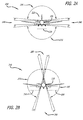
- FIG. 2A is a diagram 200 showing a dual antenna crown / undercarriage mounting that may be utilized for the antennas 225, 230 employed by the disclosed system for streaming flight data from an aircraft 205, in accordance with at least one embodiment of the present disclosure.
- an aircraft 205 is shown to have a crown antenna 225 and an undercarriage antenna 230.
- This figure shows the field of view 235 for each of these antennas 225, 230, and the blind spots 240 for this antenna configuration.
- the five (5) degree fields of views are example values.
- FIG. 2B is a diagram 210 showing a dual antenna saddlebag mounting that may be utilized for the antennas 245, 250 employed by the disclosed system for streaming flight data from an aircraft 215, in accordance with at least one embodiment of the present disclosure.
- an aircraft 215 is shown to have a left saddlebag antenna 250 and a right saddlebag antenna 245.
- This figure shows the field of view 255 for each of these antennas 245, 250, and the blind spots 260 for this antenna configuration.
- the five (5) degree fields of views are example values.
- the disclosed system for streaming flight data from an aircraft may utilize various different antenna configurations than the ones specifically disclosed in the present disclosure.
- the disclosed system for streaming flight data from an aircraft may employ various different types of aircraft including, but not limited to, commercial aircraft, helicopters, drones, and various different types of military aircraft.
- FIG. 3 is a diagram 300 illustrating a cut-away view of an aircraft 305 with an Aeronautical Radio Incorporated (ARINC) 717 interface employing the disclosed system for streaming flight data from an aircraft, in accordance with at least one embodiment of the present disclosure.
- the aircraft 305 is shown to include a flight data recorder (FDR), located towards the aft section of the aircraft 305.
- the aircraft 305 is also shown to include a digital flight data acquisition unit (DFDAU) 315 located towards the forward section of the aircraft 305.
- the aircraft 305 is shown to include a flight data recorder streaming (FDRS) server 320 and an antenna switch unit 325.
- FDR flight data recorder
- DAU digital flight data acquisition unit
- FDRS flight data recorder streaming
- the aircraft 305 is shown to employ a dual antenna crown / undercarriage mounting having a crown antenna 330 (e.g., a first antenna) and an undercarriage antenna 335 (e.g., a second antenna).
- a dual antenna saddlebag mounting having a left saddlebag antenna (e.g., a first antenna) and a right saddlebag antenna (e.g., a second antenna).
- the DFDAU 315 sends flight data to the FDR 310 via a FDR ARINC 717 interface 340.
- the FDR 310 sends playback flight data back to the DFDAU 315 via an FDR playback bus 345.
- the DFDAU 315 also sends the flight data to the FDRS server 320 via a DFDAU playback bus 350.
- the FDR 310 sends the playback flight data to the FDRS server 320 via the FDR playback bus 345.
- the FDRS server 320 After the FDRS server 320 has received the flight data from the DFDAU 315, the FDRS server 320 analyzes the flight data to determine which (or both) of the antennas 330, 335 to use for streaming of the flight data depending upon which antenna 330, 335 has visibility to at least one satellite, and/or depending upon whether at least one triggering condition has occurred. When the FDRS server 320 analyzes the flight data to determine which (or both) of the antennas 330, 335 to use for streaming of the flight data depending upon which antenna 330, 335 has visibility to at least one satellite; the FDRS server 320 will choose the antenna 330, 335 that has visibility to a satellite to stream the flight data.
- the FDRS server 320 analyzes the flight data to determine which (or both) of the antennas 330, 335 to use for streaming of the flight data depending upon which antenna 330, 335 has visibility to at least one satellite, and if the FDRS server 320 determines that antenna 330 has visibility to a satellite and antenna 335 does not have visibility to a satellite; the FDRS server 320 will determine to use antenna 330 for the streaming of the flight data.
- the FDRS server 320 When the FDRS server 320 analyzes the flight data to determine which (or both) of the antennas 330, 335 to use for streaming of the flight data depending upon whether at least one triggering condition has occurred; the FDRS server 320 will choose both antennas 330, 335 to stream the flight data when the FDRS server 320 determines that at least one triggering condition has occurred.
- Types of triggering conditions that may be employed by the disclosed system include, but are not limited to, a rate of descent threshold has been exceeded (e.g., the aircraft 305 is descending at a rate faster than the rate of descent threshold), an attitude threshold has been crossed (i.e.
- the aircraft 305 has an attitude outside of the expected attitude range), attitude and/or rate constraints have been violated (e.g., the aircraft is flying in an unstable or unexpected manner), the aircraft has been tampered with (e.g., the cockpit door, the electronic /electrical bay door, or particular onboard equipment has been sabotaged), a security alarm has gone off (e.g., an automatic alarm or an indication from a crew member or air marshal), specific crew alerts have been raised (e.g., engine out), a collision warning threshold has been exceeded (e.g., the aircraft 305 is closer to a foreign object than the threshold for safe distance), and/or a deviation from a flight plan threshold has been exceeded (e.g., the aircraft 305 has deviated from the flight plan more than an acceptable Circular Error Probability (CEP)).
- CEP Circular Error Probability
- the FDRS server 320 analyzes the flight data to determine which (or both) of the antennas 330, 335 to use for streaming of the flight data depending upon whether a triggering condition has occurred, and if the FDRS server 320 determines that at least one triggering condition has occurred (e.g., the aircraft 305 has deviated from the flight plan more than the deviation from a flight plan threshold distance); the FDRS server 320 will choose both antennas 330, 335 to stream the flight data.
- the FDRS server 320 analyzes the flight data to determine a data rate of transmission for streaming the flight data depending upon whether at least one triggering condition has occurred. If the FDRS server 320 determines that at least one triggering condition has occurred, the FDRS server 320 will set the data rate of transmission for streaming to a fast stream data rate of transmission (i.e. a fast data rate) of a full set of parameters continuously during flight. However, if the FDRS server 320 determines that at least one triggering condition has not occurred, the FDRS server 320 will set the data rate of transmission for streaming to a slow stream data rate of transmission (i.e.
- slow data rate is a data rate that is slower than the fast data rate
- the slow data rate is a data rate that is slower than the fast data rate
- the FDRS server 320 After the FDRS server 320 determines which (or both) antenna 330, 335 to use for streaming the flight data, the FDRS server 320 generates an antenna selection signal according to which (or both) antenna 330, 335 to use for streaming the flight data. The FDRS server 320 transmits the antenna selection signal to the antenna switch unit 325.
- the antenna switch unit 325 After the antenna switch unit 325 receives the antenna selection signal, the antenna switch unit 325 selects the antenna(s) 330, 335 to use for streaming the flight data according to the antenna selection signal. After the antenna(s) 330, 335 is selected by the antenna switch unit 325 to stream the flight data, the selected antenna(s) 330, 335 streams the flight data to at least one satellite (not shown).
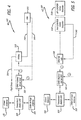
- FIG. 4 is a detailed diagram 400 showing the disclosed system for streaming flight data from an aircraft, where the aircraft employs an ARINC 717 interface, in accordance with at least one embodiment of the present disclosure.
- this figure shows a more detailed diagram than FIG. 3 of the interconnections between the various units employed by the disclosed system that employs an aircraft utilizing an ARINC 717 interface.
- the flight data is shown to be transmitted to the FDRS server 320 via (1) the DFDAU playback bus 350 (from the DFDAU 315) and/or (2) the FDR playback bus 345 (from the FDR 310).
- the operation of the units depicted in this figure is discussed in the description of FIG. 3 .
- FIG. 5 is a detailed diagram 500 showing the disclosed system for streaming flight data from an aircraft, where the aircraft employs an Ethernet interface, in accordance with at least one embodiment of the present disclosure.
- the aircraft (not shown) includes a forward cockpit voice recorder / flight data recorder (CVR/FDR) combination recorder 510f, located towards the forward section of the aircraft, and includes an aft CVR/FDR combination recorder 510a, located towards the aft section of the aircraft.
- the aircraft also includes an Ethernet hub 540.
- the aircraft includes a FDRS server 520 and an antenna switch unit 525.
- the aircraft employs a dual antenna crown / undercarriage mounting having a crown antenna 530 (e.g., a first antenna) and an undercarriage antenna 535 (e.g., a second antenna).
- a dual antenna saddlebag mounting having a left saddlebag antenna (e.g., a first antenna) and a right saddlebag antenna (e.g., a second antenna).
- the Ethernet hub 540 sends flight data to the forward CVR/FDR combination recorder 510f and the aft CVR/FDR combination recorder 510a.
- the forward CVR/FDR combination recorder 510f and the aft CVR/FDR combination recorder 510a send playback flight data back to the Ethernet hub 540 via a CVR/FDR combination recorder playback bus 545.
- the flight data is shown to be transmitted from the forward CVR/FDR combination recorder 510f and the aft CVR/FDR combination recorder 510a to the FDRS server 520 via (1) the Ethernet hub 540 and/or (2) the CVR/FDR combination recorder playback bus 545.
- the FDRS server 520 analyzes the flight data to determine which (or both) of the antennas 530, 535 to use for streaming of the flight data depending upon which antenna 530, 535 has visibility to at least one satellite, and/or depending upon whether at least one triggering condition has occurred.
- the FDRS server 520 analyzes the flight data to determine which (or both) of the antennas 530, 535 to use for streaming of the flight data depending upon which antenna 530, 535 has visibility to at least one satellite; the FDRS server 520 will choose the antenna 330, 335 that has visibility to a satellite to stream the flight data.
- the FDRS server 520 analyzes the flight data to determine which (or both) of the antennas 530, 535 to use for streaming of the flight data depending upon whether at least one triggering condition has occurred; the FDRS server 520 will choose both antennas 530, 535 to stream the flight data when the FDRS server 520 determines that at least one triggering condition has occurred.
- the FDRS server 520 analyzes the flight data to determine a data rate of transmission for streaming the flight data depending upon whether at least one triggering condition has occurred. If the FDRS server 520 determines that at least one triggering condition has occurred, the FDRS server 520 will set the data rate of transmission for streaming to a fast stream data rate of transmission (i.e. a fast data rate) of a full set of parameters continuously during flight. However, if the FDRS server 520 determines that at least one triggering condition has not occurred, the FDRS server 520 will set the data rate of transmission for streaming to a slow stream data rate of transmission (i.e.
- slow data rate is a data rate that is slower than the fast data rate
- the slow data rate is a data rate that is slower than the fast data rate
- the FDRS server 520 After the FDRS server 520 determines which (or both) antenna 530, 535 to use for streaming the flight data, the FDRS server 520 generates an antenna selection signal according to which (or both) antenna 530, 535 to use for streaming the flight data. The FDRS server 520 transmits the antenna selection signal to the antenna switch unit 525.
- the antenna switch unit 525 After the antenna switch unit 525 receives the antenna selection signal, the antenna switch unit 525 selects the antenna(s) 530, 535 to use for streaming the flight data according to the antenna selection signal. After the antenna(s) 530, 535 is selected by the antenna switch unit 525 to stream the flight data, the selected antenna(s) 530, 535 streams the flight data to at least one satellite (not shown).
- FIG. 6 is a flow chart depicting the disclosed method 600 for streaming flight data from an aircraft, in accordance with at least one embodiment of the present disclosure.
- at least one flight data unit transmits flight data to a flight data recorder streaming (FDRS) server 620.
- the FDRS server determines at least one antenna to use for streaming the flight data by analyzing the flight data 630.
- the FDRS server generates an antenna selection signal according to at least one antenna to use for streaming the flight data 640.
- the FDRS server transmits the antenna selection signal to an antenna switch unit 650.
- the antenna switch unit selects at least one antenna to use for streaming the flight data according to the antenna selection signal 660.
- At least one antenna to use for streaming the flight data streams the flight data to at least one satellite, where it is then transmitted to at least one ground station 670.
- the method 600 ends 680.
- embodiments may involve a FDRS application or algorithm (which may be run on a FDRS server onboard the aircraft or may be run on another computer at the operational center or elsewhere) that is a stand alone application, which may contain one or more programs, or that is part of another system or program.
- a FDRS application or algorithm which may be run on a FDRS server onboard the aircraft or may be run on another computer at the operational center or elsewhere
- a stand alone application which may contain one or more programs, or that is part of another system or program.
Landscapes
- Engineering & Computer Science (AREA)
- Physics & Mathematics (AREA)
- General Physics & Mathematics (AREA)
- Aviation & Aerospace Engineering (AREA)
- Signal Processing (AREA)
- Computer Networks & Wireless Communication (AREA)
- Astronomy & Astrophysics (AREA)
- Multimedia (AREA)
- Emergency Management (AREA)
- Business, Economics & Management (AREA)
- General Health & Medical Sciences (AREA)
- Computing Systems (AREA)
- Medical Informatics (AREA)
- Health & Medical Sciences (AREA)
- Radio Relay Systems (AREA)
- Variable-Direction Aerials And Aerial Arrays (AREA)
- Mobile Radio Communication Systems (AREA)
- Details Of Aerials (AREA)
Abstract
Description
- The present disclosure relates to flight data recorders. In particular, it relates to flight data recorder streaming (FDRS) solutions.
- Currently, with very few exceptions, flight data recorder (FDR) data is accessed on the ground. This is a problem because aircraft operations centers must depend on very infrequent Aircraft Communication Addressing and Reporting System (ACARS) messaging of position and failures for accident prevention as well as crash location and investigation, and even then, ACARS is only currently deployed on newer aircraft. Currently, there is no significant deployment of an FDR streaming solution from the air. It is not a basic provision on commercial airplanes. However, the national transportation safety board (NTSB) is now recommending FDRS capability for long flights over water. As such, there is need for FDRS solutions.
- The present disclosure relates to a method, system, and apparatus for flight data recorder streaming (FDRS) solutions. In one or more embodiments, a method for streaming flight data from an aircraft involves transmitting, from at least one flight data unit, the flight data to a flight data recorder streaming (FDRS) server. The method further involves determining, by the FDRS server, at least one antenna to use for streaming the flight data by analyzing the flight data. In one or more embodiments, at least one antenna comprises a first antenna and/or a second antenna. Also, the method involves generating, by the FDRS server, an antenna selection signal according to at least one antenna to use for streaming the flight data. In addition, the method involves transmitting, by the FDRS server, an antenna selection signal to an antenna switch unit. Additionally, the method involves selecting, by the antenna switch unit, at least one antenna to use for streaming the flight data according to the antenna selection signal. Further, the method involves streaming, by at least one antenna to use for streaming the flight data, the flight data to at least one satellite. In one or more embodiments, the flight data is then transmitted from at least one satellite to at least one ground station.
- In one or more embodiments, at least one flight data unit is at least one of a flight data recorder (FDR) and/or a cockpit voice recorder / flight data recorder (CVR/FDR) combination recorder. In at least one embodiment, when at least one flight data unit is a FDR, the flight data is transmitted to the FDRS server via a digital flight data acquisition unit (DFDAU) playback bus or a FDR playback bus. In some embodiments, when at least one flight data unit is a CVR/FDR combination recorder, the flight data is transmitted to the FDRS server via an Ethernet hub or a CVR/FDR combination recorder playback bus.
- In at least one embodiment, the first antenna is a crown antenna, and the second antenna is an undercarriage antenna. In some embodiments, the first antenna is a left saddlebag antenna, and the second antenna is a right saddlebag antenna.
- In one or more embodiments, the FDRS server is configured to determine at least one antenna to use for streaming the flight data by analyzing the flight data to determine at least one antenna that has visibility to at least one satellite.
- In at least one embodiment, the FDRS server determines at least one antenna to use for streaming the flight data by analyzing the flight data to determine whether at least one triggering condition has occurred. In some embodiments, when the FDRS server determines that at least one triggering condition has occurred, the FDRS server determines that both of the antennas are to be used for streaming the flight data.
- In one or more embodiments, the method further involves determining, by the FDRS server, a data rate of transmission for streaming the flight data by analyzing the flight data to determine whether at least one triggering condition has occurred. In at least one embodiment, the triggering condition is at least one of following: a rate of descent threshold has been exceeded, an attitude threshold has been crossed, a collision warning threshold has been exceeded, the aircraft has been sabotaged, the aircraft is flying in an unexpected matter, an adverse security condition exists onboard the aircraft, and a deviation from a flight plan threshold has been exceeded. In some embodiments, when the FDRS server determines that at least one triggering condition has occurred, the FDRS server sets the data rate of transmission for streaming to a fast stream data rate of transmission. In one or more embodiments, when the FDRS server determines that at least one triggering condition has not occurred, the FDRS server sets the data rate of transmission for streaming to a slow stream data rate of transmission.
- In at least one embodiment, a system for a streaming flight data from an aircraft involves at least one flight data unit configured to transmit the flight data to a flight data recorder streaming (FDRS) server. The system further involves the FDRS server configured to determine at least one antenna to use for streaming the flight data by analyzing the flight data (where at least one antenna comprises a first antenna and/or a second antenna); to generate an antenna selection signal according to at least one antenna to use for streaming the flight data; and to transmit an antenna selection signal to an antenna switch unit. Also, the system involves the antenna switch unit configured to select at least one antenna to use for streaming the flight data according to the antenna selection signal. Further, the system involves at least one antenna configured to be used for streaming the flight data to stream the flight data to at least one satellite. In one or more embodiments, the flight data is then transmitted from at least one satellite to at least one ground station.
- In one or more embodiments, the FDRS server is further to determine a data rate of transmission for streaming the flight data by analyzing the flight data to determine whether at least one triggering condition has occurred.
- The features, functions, and advantages can be achieved independently in various embodiments of the present disclosure or may be combined in yet other embodiments.
- These and other features, aspects, and advantages of the present disclosure will become better understood with regard to the following description, appended claims, and accompanying drawings where:
-
FIG. 1 is a diagram depicting the disclosed system for streaming flight data from an aircraft, in accordance with at least one embodiment of the present disclosure. -
FIG. 2A is a diagram showing a dual antenna crown / undercarriage mounting that may be utilized for the antennas employed by the disclosed system for streaming flight data from an aircraft, in accordance with at least one embodiment of the present disclosure. -
FIG. 2B is a diagram showing a dual antenna saddlebag mounting that may be utilized for the antennas employed by the disclosed system for streaming flight data from an aircraft, in accordance with at least one embodiment of the present disclosure. -
FIG. 3 is a diagram illustrating a cut-away view of an aircraft with an Aeronautical Radio Incorporated (ARINC) 717 interface employing the disclosed system for streaming flight data from an aircraft, in accordance with at least one embodiment of the present disclosure. -
FIG. 4 is a detailed diagram showing the disclosed system for streaming flight data from an aircraft, where the aircraft employs an ARINC 717 interface, in accordance with at least one embodiment of the present disclosure. -
FIG. 5 is a detailed diagram showing the disclosed system for streaming flight data from an aircraft, where the aircraft employs an Ethernet interface, in accordance with at least one embodiment of the present disclosure. -
FIG. 6 is a flow chart depicting the disclosed method for streaming flight data from an aircraft, in accordance with at least one embodiment of the present disclosure. - The methods and apparatus disclosed herein provide an operative system for flight data recorder streaming (FDRS) solutions. The system of the present disclosure teaches a streaming solution that employs a dual antenna configuration on the aircraft for streaming of the flight data to at least one satellite, where it is then transmitted to at least one ground station. In addition, the system utilizes varied data rates for streaming of the flight data depending upon the occurrence of at least one triggering condition.
- In one or more embodiments, the disclosed system utilizes at least one geostationary earth orbit (GEO) satellite (e.g., Inmarsat). In some embodiments, the disclosed system utilizes at least one low earth orbit (LEO) satellite and/or at least one medium earth orbit (MEO) satellite. Also, in some embodiments, the disclosed system utilizes at least one satellite in a circular orbit and/or at least one satellite in an elliptical orbit. The disclosed system can be installed on production commercial aircraft to stream selected FDR parameters to capture anomalous events (e.g., the flight data includes information relating to inflight equipment issues) and safety incidents and to geolocate a crash site (e.g., the flight data includes tracking information) in a timely manner. In some embodiments, the disclosed system can be installed on production commercial aircraft to stream information from a cockpit voice recorder (CVR) onboard the aircraft. While the disclosed system is related to safety, the implementation of the disclosed system will not encumber the safety critical systems and interfaces of the aircraft. To speed deployment, the system will require little regulatory approval or industry-wide coordination, and be developed as a non-standardized unique solution. It should be noted that the disclosed system is neither a replacement for current flight data recorders (FDRs) nor a solution for streaming cockpit voice recorders (CVRs).
- In at least one embodiment, the disclosed system employs a triggering solution. For the triggering solution, the disclosed system utilizes a slow stream (i.e. a slow data rate) of a minimum set of parameters continuously during flight; with the exception of the latitude, longitude, and altitude parameters, which will be streamed at a fast stream (i.e. a fast data rate, which is a faster data rate than the slow data rate). When a FDRS server determines that a triggering condition has occurred, the disclosed system utilizes a fast stream (i.e. a fast data rate) of a full set of parameters continuously during flight.
- In one or more embodiments, the disclosed system employs a dual antenna configuration for the streaming of the flight data. The FDRS server determines, by analyzing the flight data, whether to employ a first antenna and/or a second antenna of the dual antenna configuration for the streaming of the flight data depending upon the visibility of at least one satellite to the antennas and/or depending upon whether a triggering condition has occurred.
- In the following description, numerous details are set forth in order to provide a more thorough description of the system. It will be apparent, however, to one skilled in the art, that the disclosed system may be practiced without these specific details. In the other instances, well known features have not been described in detail so as not to unnecessarily obscure the system.
- Embodiments of the present disclosure may be described herein in terms of functional and/or logical components and various processing steps. It should be appreciated that such components may be realized by any number of hardware, software, and/or firmware components configured to perform the specified functions. For example, an embodiment of the present disclosure may employ various integrated circuit components (e.g., memory elements, digital signal processing elements, logic elements, look-up tables, or the like), which may carry out a variety of functions under the control of one or more processors, microprocessors, or other control devices. In addition, those skilled in the art will appreciate that embodiments of the present disclosure may be practiced in conjunction with other components, and that the system described herein is merely one example embodiment of the present disclosure.
- For the sake of brevity, conventional techniques and components related to streaming flight data, and other functional aspects of the system (and the individual operating components of the systems) may not be described in detail herein. Furthermore, the connecting lines shown in the various figures contained herein are intended to represent example functional relationships and/or physical couplings between the various elements. It should be noted that many alternative or additional functional relationships or physical connections may be present in an embodiment of the present disclosure.
-
FIG. 1 is a diagram 100 depicting the disclosed system for streaming flight data from an aircraft, in accordance with at least one embodiment of the present disclosure. In this figure, at least one antenna (not shown) on anaircraft 105 is transmitting (i.e. streaming) 110 flight data to asatellite 115. Thesatellite 115 is a member of a constellation of satellites (e.g., the constellation containssatellites satellites satellites - Also in this figure,
satellite 115 is transmitting 130 the flight data to at least onesatellite ground station 135. The satellite ground station(s) 135 transmits the flight data via theinternet 140 toairlines operations centers 145, to theaircraft manufacturer 150, to thegovernment 155, to a secure server andportal device 160, and/or to a backup secure server andportal 165. -
FIG. 2A is a diagram 200 showing a dual antenna crown / undercarriage mounting that may be utilized for theantennas aircraft 205, in accordance with at least one embodiment of the present disclosure. In this figure, anaircraft 205 is shown to have acrown antenna 225 and anundercarriage antenna 230. This figure shows the field ofview 235 for each of theseantennas blind spots 240 for this antenna configuration. The five (5) degree fields of views are example values. -
FIG. 2B is a diagram 210 showing a dual antenna saddlebag mounting that may be utilized for theantennas aircraft 215, in accordance with at least one embodiment of the present disclosure. In this figure, anaircraft 215 is shown to have aleft saddlebag antenna 250 and aright saddlebag antenna 245. This figure shows the field ofview 255 for each of theseantennas blind spots 260 for this antenna configuration. The five (5) degree fields of views are example values. - It should be noted that in other embodiments, the disclosed system for streaming flight data from an aircraft may utilize various different antenna configurations than the ones specifically disclosed in the present disclosure. In addition, it should be noted that the disclosed system for streaming flight data from an aircraft may employ various different types of aircraft including, but not limited to, commercial aircraft, helicopters, drones, and various different types of military aircraft.
-
FIG. 3 is a diagram 300 illustrating a cut-away view of anaircraft 305 with an Aeronautical Radio Incorporated (ARINC) 717 interface employing the disclosed system for streaming flight data from an aircraft, in accordance with at least one embodiment of the present disclosure. In this figure, theaircraft 305 is shown to include a flight data recorder (FDR), located towards the aft section of theaircraft 305. Theaircraft 305 is also shown to include a digital flight data acquisition unit (DFDAU) 315 located towards the forward section of theaircraft 305. Also, theaircraft 305 is shown to include a flight data recorder streaming (FDRS)server 320 and anantenna switch unit 325. - In this figure, the
aircraft 305 is shown to employ a dual antenna crown / undercarriage mounting having a crown antenna 330 (e.g., a first antenna) and an undercarriage antenna 335 (e.g., a second antenna). However, it should be noted that in other embodiments, the aircraft may employ a dual antenna saddlebag mounting having a left saddlebag antenna (e.g., a first antenna) and a right saddlebag antenna (e.g., a second antenna). - During operation of the disclosed system, during flight, the
DFDAU 315 sends flight data to theFDR 310 via a FDR ARINC 717interface 340. TheFDR 310 sends playback flight data back to theDFDAU 315 via anFDR playback bus 345. TheDFDAU 315 also sends the flight data to theFDRS server 320 via aDFDAU playback bus 350. In some embodiments, theFDR 310 sends the playback flight data to theFDRS server 320 via theFDR playback bus 345. - After the
FDRS server 320 has received the flight data from theDFDAU 315, theFDRS server 320 analyzes the flight data to determine which (or both) of theantennas antenna FDRS server 320 analyzes the flight data to determine which (or both) of theantennas antenna FDRS server 320 will choose theantenna FDRS server 320 analyzes the flight data to determine which (or both) of theantennas antenna FDRS server 320 determines thatantenna 330 has visibility to a satellite andantenna 335 does not have visibility to a satellite; theFDRS server 320 will determine to useantenna 330 for the streaming of the flight data. - When the
FDRS server 320 analyzes the flight data to determine which (or both) of theantennas FDRS server 320 will choose bothantennas FDRS server 320 determines that at least one triggering condition has occurred. Types of triggering conditions that may be employed by the disclosed system include, but are not limited to, a rate of descent threshold has been exceeded (e.g., theaircraft 305 is descending at a rate faster than the rate of descent threshold), an attitude threshold has been crossed (i.e. theaircraft 305 has an attitude outside of the expected attitude range), attitude and/or rate constraints have been violated (e.g., the aircraft is flying in an unstable or unexpected manner), the aircraft has been tampered with (e.g., the cockpit door, the electronic /electrical bay door, or particular onboard equipment has been sabotaged), a security alarm has gone off (e.g., an automatic alarm or an indication from a crew member or air marshal), specific crew alerts have been raised (e.g., engine out), a collision warning threshold has been exceeded (e.g., theaircraft 305 is closer to a foreign object than the threshold for safe distance), and/or a deviation from a flight plan threshold has been exceeded (e.g., theaircraft 305 has deviated from the flight plan more than an acceptable Circular Error Probability (CEP)). For example, if theFDRS server 320 analyzes the flight data to determine which (or both) of theantennas FDRS server 320 determines that at least one triggering condition has occurred (e.g., theaircraft 305 has deviated from the flight plan more than the deviation from a flight plan threshold distance); theFDRS server 320 will choose bothantennas - Also, after the
FDRS server 320 has received the flight data from theDFDAU 315, theFDRS server 320 analyzes the flight data to determine a data rate of transmission for streaming the flight data depending upon whether at least one triggering condition has occurred. If theFDRS server 320 determines that at least one triggering condition has occurred, theFDRS server 320 will set the data rate of transmission for streaming to a fast stream data rate of transmission (i.e. a fast data rate) of a full set of parameters continuously during flight. However, if theFDRS server 320 determines that at least one triggering condition has not occurred, theFDRS server 320 will set the data rate of transmission for streaming to a slow stream data rate of transmission (i.e. a slow data rate, where the slow data rate is a data rate that is slower than the fast data rate) of a minimum set of parameters continuously during flight, with the exception of the latitude, longitude, and altitude parameters, which will be streamed at a fast stream data rate of transmission. - After the
FDRS server 320 determines which (or both)antenna FDRS server 320 generates an antenna selection signal according to which (or both)antenna FDRS server 320 transmits the antenna selection signal to theantenna switch unit 325. - After the
antenna switch unit 325 receives the antenna selection signal, theantenna switch unit 325 selects the antenna(s) 330, 335 to use for streaming the flight data according to the antenna selection signal. After the antenna(s) 330, 335 is selected by theantenna switch unit 325 to stream the flight data, the selected antenna(s) 330, 335 streams the flight data to at least one satellite (not shown). -
FIG. 4 is a detailed diagram 400 showing the disclosed system for streaming flight data from an aircraft, where the aircraft employs an ARINC 717 interface, in accordance with at least one embodiment of the present disclosure. In particular, this figure shows a more detailed diagram thanFIG. 3 of the interconnections between the various units employed by the disclosed system that employs an aircraft utilizing an ARINC 717 interface. In this figure, the flight data is shown to be transmitted to theFDRS server 320 via (1) the DFDAU playback bus 350 (from the DFDAU 315) and/or (2) the FDR playback bus 345 (from the FDR 310). The operation of the units depicted in this figure is discussed in the description ofFIG. 3 . -
FIG. 5 is a detailed diagram 500 showing the disclosed system for streaming flight data from an aircraft, where the aircraft employs an Ethernet interface, in accordance with at least one embodiment of the present disclosure. In this figure, the aircraft (not shown) includes a forward cockpit voice recorder / flight data recorder (CVR/FDR)combination recorder 510f, located towards the forward section of the aircraft, and includes an aft CVR/FDR combination recorder 510a, located towards the aft section of the aircraft. The aircraft also includes anEthernet hub 540. Also, the aircraft includes aFDRS server 520 and anantenna switch unit 525. - In this figure, the aircraft employs a dual antenna crown / undercarriage mounting having a crown antenna 530 (e.g., a first antenna) and an undercarriage antenna 535 (e.g., a second antenna). However, it should be noted that in other embodiments, the aircraft may employ a dual antenna saddlebag mounting having a left saddlebag antenna (e.g., a first antenna) and a right saddlebag antenna (e.g., a second antenna).
- During operation of the disclosed system, during flight, the
Ethernet hub 540 sends flight data to the forward CVR/FDR combination recorder 510f and the aft CVR/FDR combination recorder 510a. The forward CVR/FDR combination recorder 510f and the aft CVR/FDR combination recorder 510a send playback flight data back to theEthernet hub 540 via a CVR/FDR combinationrecorder playback bus 545. In this figure, the flight data is shown to be transmitted from the forward CVR/FDR combination recorder 510f and the aft CVR/FDR combination recorder 510a to theFDRS server 520 via (1) theEthernet hub 540 and/or (2) the CVR/FDR combinationrecorder playback bus 545. - After the
FDRS server 520 has received the flight data, theFDRS server 520 analyzes the flight data to determine which (or both) of theantennas antenna FDRS server 520 analyzes the flight data to determine which (or both) of theantennas antenna FDRS server 520 will choose theantenna - When the
FDRS server 520 analyzes the flight data to determine which (or both) of theantennas FDRS server 520 will choose bothantennas FDRS server 520 determines that at least one triggering condition has occurred. - Also, after the
FDRS server 520 has received the flight data, theFDRS server 520 analyzes the flight data to determine a data rate of transmission for streaming the flight data depending upon whether at least one triggering condition has occurred. If theFDRS server 520 determines that at least one triggering condition has occurred, theFDRS server 520 will set the data rate of transmission for streaming to a fast stream data rate of transmission (i.e. a fast data rate) of a full set of parameters continuously during flight. However, if theFDRS server 520 determines that at least one triggering condition has not occurred, theFDRS server 520 will set the data rate of transmission for streaming to a slow stream data rate of transmission (i.e. a slow data rate, where the slow data rate is a data rate that is slower than the fast data rate) of a minimum set of parameters continuously during flight, with the exception of the latitude, longitude, and altitude parameters, which will be streamed at a fast stream data rate of transmission. - After the
FDRS server 520 determines which (or both)antenna FDRS server 520 generates an antenna selection signal according to which (or both)antenna FDRS server 520 transmits the antenna selection signal to theantenna switch unit 525. - After the
antenna switch unit 525 receives the antenna selection signal, theantenna switch unit 525 selects the antenna(s) 530, 535 to use for streaming the flight data according to the antenna selection signal. After the antenna(s) 530, 535 is selected by theantenna switch unit 525 to stream the flight data, the selected antenna(s) 530, 535 streams the flight data to at least one satellite (not shown). -
FIG. 6 is a flow chart depicting the disclosedmethod 600 for streaming flight data from an aircraft, in accordance with at least one embodiment of the present disclosure. At thestart 610 of themethod 600, at least one flight data unit transmits flight data to a flight data recorder streaming (FDRS)server 620. The FDRS server determines at least one antenna to use for streaming the flight data by analyzing the flight data 630. The FDRS server generates an antenna selection signal according to at least one antenna to use for streaming theflight data 640. The FDRS server transmits the antenna selection signal to anantenna switch unit 650. The antenna switch unit selects at least one antenna to use for streaming the flight data according to the antenna selection signal 660. At least one antenna to use for streaming the flight data streams the flight data to at least one satellite, where it is then transmitted to at least oneground station 670. Then, themethod 600 ends 680. - Although particular embodiments have been shown and described, it should be understood that the above discussion is not intended to limit the scope of these embodiments. While embodiments and variations of the many aspects of the invention have been disclosed and described herein, such disclosure is provided for purposes of explanation and illustration only. Thus, various changes and modifications may be made without departing from the scope of the claims.
- As a further example, embodiments may involve a FDRS application or algorithm (which may be run on a FDRS server onboard the aircraft or may be run on another computer at the operational center or elsewhere) that is a stand alone application, which may contain one or more programs, or that is part of another system or program.
- Although particular embodiments have been shown and described, it should be understood that the above discussion is not intended to limit the scope of these embodiments. While embodiments and variations of the many aspects of the present disclosure have been disclosed and described herein, such disclosure is provided for purposes of explanation and illustration only. Thus, various changes and modifications may be made without departing from the scope of the claims.
- Where methods described above indicate certain events occurring in certain order, those of ordinary skill in the art having the benefit of this disclosure would recognize that the ordering may be modified and that such modifications are in accordance with the variations of the present disclosure. Additionally, parts of methods may be performed concurrently in a parallel process when possible, as well as performed sequentially. In addition, more parts or less part of the methods may be performed.
- Accordingly, embodiments are intended to exemplify alternatives, modifications, and equivalents that may fall within the scope of the claims.
- Although certain illustrative embodiments and methods have been disclosed herein, it can be apparent from the foregoing disclosure to those skilled in the art that variations and modifications of such embodiments and methods can be made without departing from the true spirit and scope of the art disclosed. Many other examples of the art disclosed exist, each differing from others in matters of detail only. Accordingly, it is intended that the art disclosed shall be limited only to the extent required by the appended claims and the rules and principles of applicable law.
Claims (15)
- A method for a streaming flight data from an aircraft, the method comprising:transmitting, from at least one flight data unit, the flight data to a flight data recorder streaming (FDRS) server;determining, by the FDRS server, at least one antenna to use for streaming the flight data by analyzing the flight data, wherein the at least one antenna comprises at least one of a first antenna and a second antenna;generating, by the FDRS server, an antenna selection signal according to the at least one antenna to use for streaming the flight data;transmitting, by the FDRS server, the antenna selection signal to an antenna switch unit;selecting, by the antenna switch unit, the at least one antenna to use for streaming the flight data according to the antenna selection signal; andstreaming, by the at least one antenna to use for streaming the flight data, the flight data to at least one of at least one satellite.
- The method of claim 1, wherein the FDRS server determines the at least one antenna to use for streaming the flight data by analyzing the flight data to determine the at least one antenna that has visibility to at least one of the at least one satellite.
- The method of claim 1 or 2, wherein the FDRS server determines the at least one antenna to use for streaming the flight data by analyzing the flight data to determine whether at least one triggering condition has occurred.
- The method of claim 3, wherein when the FDRS server determines that at least one of the at least one triggering condition has occurred, the FDRS server determines that both of the at least one antenna are to be used for streaming the flight data.
- The method any one of the preceding claims, wherein the method further comprises determining, by the FDRS server, a data rate of transmission for streaming the flight data by analyzing the flight data to determine whether at least one triggering condition has occurred.
- The method of any one of claims 3-5, wherein the at least one triggering condition is at least one of a rate of descent threshold has been exceeded, an attitude threshold has been crossed, a collision warning threshold has been exceeded, the aircraft has been sabotaged, the aircraft is flying in an unexpected matter, an adverse security condition exists onboard the aircraft, and a deviation from a flight plan threshold has been exceeded.
- The method of any one of claims 3-6, wherein when the FDRS server determines that at least one of the at least one triggering condition has occurred, the FDRS server sets the data rate of transmission for streaming to a fast stream data rate of transmission.
- The method of any one of claims 3-6, wherein when the FDRS server determines that at least one of the at least one triggering condition has not occurred, the FDRS server sets the data rate of transmission for streaming to a slow stream data rate of transmission.
- A system for a streaming flight data from an aircraft, the system comprising:at least one flight data unit to transmit the flight data to a flight data recorder streaming (FDRS) server;the FDRS server to determine at least one antenna to use for streaming the flight data by analyzing the flight data, wherein the at least one antenna comprises at least one of a first antenna and a second antenna, to generate an antenna selection signal according to the at least one antenna to use for streaming the flight data, and to transmit the antenna selection signal to an antenna switch unit;the antenna switch unit to select the at least one antenna to use for streaming the flight data according to the antenna selection signal; andthe at least one antenna to use for streaming the flight data to stream the flight data to at least one of at least one satellite.
- The system of claim 9, wherein the at least one flight data unit is at least one of a flight data recorder (FDR) and a cockpit voice recorder / flight data recorder (CVR/FDR) combination recorder.
- The system of claim 10, wherein when the at least one flight data unit is a FDR, the flight data is transmitted to the FDRS server via one of a digital flight data acquisition unit (DFDAU) playback bus or a FDR playback bus.
- The system of claim 10, wherein when the at least one flight data unit is a CVR/FDR combination recorder, the flight data is transmitted to the FDRS server via one of an Ethernet hub or a CVR/FDR combination recorder playback bus.
- The system of any one of claims 9-12, wherein the first antenna is a crown antenna and the second antenna is an undercarriage antenna.
- The system of any one of claims 9-12, wherein the first antenna is a left saddlebag antenna and the second antenna is a right saddlebag antenna.
- The system of ane one of claims 9-14, wherein the FDRS server determines the at least one antenna to use for streaming the flight data by analyzing the flight data to determine the at least one antenna that has visibility to at least one of the at least one satellite.
Applications Claiming Priority (1)
| Application Number | Priority Date | Filing Date | Title |
|---|---|---|---|
| US14/838,113 US10348787B2 (en) | 2015-08-27 | 2015-08-27 | Flight data recorder streaming (FDRS) solution |
Publications (2)
| Publication Number | Publication Date |
|---|---|
| EP3135589A1 true EP3135589A1 (en) | 2017-03-01 |
| EP3135589B1 EP3135589B1 (en) | 2019-11-06 |
Family
ID=56936254
Family Applications (1)
| Application Number | Title | Priority Date | Filing Date |
|---|---|---|---|
| EP16185888.1A Active EP3135589B1 (en) | 2015-08-27 | 2016-08-26 | Flight data recorder streaming (fdrs) solution |
Country Status (4)
| Country | Link |
|---|---|
| US (1) | US10348787B2 (en) |
| EP (1) | EP3135589B1 (en) |
| JP (1) | JP6842259B2 (en) |
| CN (1) | CN106487439B (en) |
Cited By (3)
| Publication number | Priority date | Publication date | Assignee | Title |
|---|---|---|---|---|
| EP3296977A1 (en) * | 2016-09-19 | 2018-03-21 | Honeywell International Inc. | Dynamic flight tracking system using airborne communications and ground data services |
| DE102017202494A1 (en) | 2017-02-16 | 2018-08-16 | Airbus Operations Gmbh | Communication method, communication system and aerospace vehicle |
| US10524094B2 (en) | 2017-02-16 | 2019-12-31 | Airbus Operations Gmbh | Communication system, aircraft/spacecraft and communication method |
Families Citing this family (12)
| Publication number | Priority date | Publication date | Assignee | Title |
|---|---|---|---|---|
| IL246554B (en) | 2016-06-30 | 2021-10-31 | Israel Aerospace Ind Ltd | Depolyable emergency situation awareness support system |
| CN107231185B (en) * | 2017-06-06 | 2020-06-02 | 北京邮电大学 | Machine-ground wireless communication device and method based on ADS-B signals |
| US10355773B1 (en) * | 2018-01-02 | 2019-07-16 | Talal Awad | Connectivity system and method for high speed aircraft internet |
| US10748433B2 (en) * | 2018-01-05 | 2020-08-18 | Ge Aviation Systems Llc | Systems and methods for autonomous distress tracking in aerial vehicles |
| US10748359B2 (en) | 2018-01-24 | 2020-08-18 | Honeywell International Inc. | Method and system for data reporting using customized triggers |
| US11100726B2 (en) | 2018-06-01 | 2021-08-24 | Honeywell International Inc. | Systems and methods for real-time streaming of flight data |
| WO2020077105A1 (en) * | 2018-10-11 | 2020-04-16 | L3 Technologies, Inc. | Systems and methods for using flight data recorder data |
| US11044177B2 (en) * | 2018-12-24 | 2021-06-22 | Panasonic Avionics Corporation | Secure wireless vehicle parameter streaming |
| US12492008B2 (en) * | 2022-03-08 | 2025-12-09 | Textron Innovations Inc. | Cockpit voice recorder decoder |
| US12333872B2 (en) | 2022-09-23 | 2025-06-17 | The Boeing Company | Vehicle control usage monitoring |
| US12488697B2 (en) * | 2022-09-28 | 2025-12-02 | The Boeing Company | Methods and apparatus for monitoring aircraft descent rates |
| EP4601215A1 (en) * | 2024-02-09 | 2025-08-13 | Airbus S.A.S. | Method, control unit and communication system for providing a data connection, and vehicle comprising same |
Citations (3)
| Publication number | Priority date | Publication date | Assignee | Title |
|---|---|---|---|---|
| US6385513B1 (en) * | 1998-12-08 | 2002-05-07 | Honeywell International, Inc. | Satellite emergency voice/data downlink |
| US20030135311A1 (en) * | 2002-01-17 | 2003-07-17 | Levine Howard B. | Aircraft flight and voice data recorder system and method |
| US20130158751A1 (en) * | 2011-12-15 | 2013-06-20 | The Boeing Company | Stand Alone Aircraft Flight Data Transmitter |
Family Cites Families (50)
| Publication number | Priority date | Publication date | Assignee | Title |
|---|---|---|---|---|
| US5469472A (en) | 1993-10-29 | 1995-11-21 | House; Robert W. | Message substitution in a digital communication system |
| US5469471A (en) | 1994-02-01 | 1995-11-21 | Qualcomm Incorporated | Method and apparatus for providing a communication link quality indication |
| US5712712A (en) | 1995-06-01 | 1998-01-27 | Rapidata Systems, Inc. | Rapid delivery of facsimile or other data sets to a massive number of recipients |
| FR2786645B1 (en) | 1998-11-26 | 2000-12-29 | Cit Alcatel | MANAGEMENT OF PRIORITIES FOR ROUTING CALLS IN A TELECOMMUNICATIONS NETWORK |
| FR2806167B1 (en) | 2000-03-10 | 2003-12-12 | Architecture Et Conception De | TIME AND SPECTRAL SPREAD UNDERWATER LOCATION TRANSMITTER, AND METHOD AND INSTALLATION USING SUCH TRANSMITTERS |
| US6549162B1 (en) * | 2001-06-12 | 2003-04-15 | Qualcomm, Inc. | Method and apparatus for transmitting real time data from aircraft to ground stations using a data protocol over a satellite system |
| CN1167296C (en) * | 2001-09-28 | 2004-09-15 | 华为技术有限公司 | Method and device for controlling transmission rate in communication system |
| US20030152145A1 (en) * | 2001-11-15 | 2003-08-14 | Kevin Kawakita | Crash prevention recorder (CPR)/video-flight data recorder (V-FDR)/cockpit-cabin voice recorder for light aircraft with an add-on option for large commercial jets |
| US20030225492A1 (en) * | 2002-05-29 | 2003-12-04 | Cope Gary G. | Flight data transmission via satellite link and ground storage of data |
| US7042392B2 (en) | 2003-05-30 | 2006-05-09 | The Boeing Company | GPS access system and method |
| US7489926B2 (en) | 2004-01-15 | 2009-02-10 | The Boeing Company | LEO-based positioning system for indoor and stand-alone navigation |
| US7904243B2 (en) | 2004-01-15 | 2011-03-08 | The Boeing Company | Real-time data aiding for enhanced GPS performance |
| US7652594B2 (en) | 2005-04-08 | 2010-01-26 | Trigger California, Inc. | Architecture for creating, organizing, editing, management and delivery of locationally-specific information to a user in the field |
| US7372400B2 (en) | 2005-11-07 | 2008-05-13 | The Boeing Company | Methods and apparatus for a navigation system with reduced susceptibility to interference and jamming |
| US20070268914A1 (en) | 2006-02-16 | 2007-11-22 | Broadops, Llc | Tenant network controller apparatus and method |
| US7619559B2 (en) | 2006-03-15 | 2009-11-17 | The Boeing Company | Method and system for all-in-view coherent GPS signal PRN codes acquisition and navigation solution determination |
| US7579986B2 (en) | 2006-03-15 | 2009-08-25 | The Boeing Company | Method and system for all-in-view coherent GPS signal PRN codes acquisition and navigation solution determination |
| US7688261B2 (en) | 2006-03-15 | 2010-03-30 | The Boeing Company | Global position system (GPS) user receiver and geometric surface processing for all-in-view coherent GPS signal PRN codes acquisition and navigation solution |
| US20090254392A1 (en) | 2006-03-30 | 2009-10-08 | Zander Van S | Method and system for enterprise network access control and management for government and corporate entities |
| US7554481B2 (en) | 2006-05-18 | 2009-06-30 | The Boeing Company | Localized jamming of navigation signals |
| US7583225B2 (en) | 2006-05-18 | 2009-09-01 | The Boeing Company | Low earth orbit satellite data uplink |
| US8296051B2 (en) | 2006-05-18 | 2012-10-23 | The Boeing Company | Generalized high performance navigation system |
| US7579987B2 (en) | 2006-05-18 | 2009-08-25 | The Boeing Company | Low earth orbit satellite providing navigation signals |
| CN101178833B (en) * | 2006-11-10 | 2011-03-23 | 中兴通讯股份有限公司 | High efficient low false alarming rate remote monitoring system and method |
| US7468696B2 (en) | 2006-12-14 | 2008-12-23 | The Boeing Company | Method and device for trilateration using LOS link prediction and pre-measurement LOS path filtering |
| US7701393B2 (en) | 2006-12-19 | 2010-04-20 | The Boeing Company | Radio frequency navigation using frequency response matching |
| US7783301B2 (en) | 2006-12-19 | 2010-08-24 | The Boeing Company | Method and device for determining a location of a communications device |
| US20080291113A1 (en) * | 2007-05-21 | 2008-11-27 | Cheng-Yi Ou-Yang | Antenna switching system and related method for switching between first and second antennas having different gains |
| US20090228210A1 (en) | 2007-06-28 | 2009-09-10 | The Boeing Company | Navigation system based on neutrino detection |
| US7969352B2 (en) | 2008-01-08 | 2011-06-28 | The Boeing Company | Global positioning system accuracy enhancement |
| CN101527622A (en) * | 2008-03-07 | 2009-09-09 | 富士通株式会社 | MIMO-HARQ communication system and communication method |
| US9009796B2 (en) | 2010-11-18 | 2015-04-14 | The Boeing Company | Spot beam based authentication |
| US7952518B2 (en) | 2008-05-30 | 2011-05-31 | The Boeing Company | Internet hotspots localization using satellite systems |
| US8035558B2 (en) | 2008-05-30 | 2011-10-11 | The Boeing Company | Precise absolute time transfer from a satellite system |
| US7859455B2 (en) | 2009-01-06 | 2010-12-28 | The Boeing Company | Local clock frequency calibration using low earth orbit (LEO) satellites |
| US8238346B2 (en) | 2009-07-09 | 2012-08-07 | The Boeing Company | Queuing architectures for orthogonal requirements in quality of service (QoS) |
| US8752142B2 (en) | 2009-07-17 | 2014-06-10 | American Express Travel Related Services Company, Inc. | Systems, methods, and computer program products for adapting the security measures of a communication network based on feedback |
| JP5498074B2 (en) * | 2009-07-21 | 2014-05-21 | 株式会社Ihiエアロスペース | Antenna device |
| WO2011017812A1 (en) * | 2009-08-11 | 2011-02-17 | Aeromechanical Services Ltd. | Automated aircraft flight data delivery and management system with demand mode |
| US20120072990A1 (en) | 2010-09-22 | 2012-03-22 | The Boeing Company | Cost function for data transmission |
| WO2012073763A1 (en) * | 2010-11-29 | 2012-06-07 | オリンパスメディカルシステムズ株式会社 | Reception device and capsule-type endoscope system |
| US20130155450A1 (en) * | 2011-12-19 | 2013-06-20 | Brother Kogyo Kabushiki Kaisha | Recording apparatus having a plurality of antennas |
| CN102608636B (en) * | 2012-03-16 | 2013-06-19 | 中国民航大学 | A step-by-step interrogation-response positioning system for flight data recorders |
| US9069070B2 (en) * | 2012-06-01 | 2015-06-30 | Honeywell International Inc. | Systems and methods for the selection of antennas in aircraft navigation systems |
| CN102750758A (en) * | 2012-07-06 | 2012-10-24 | 陈国平 | Flight recording system with high safety |
| US9030348B2 (en) * | 2012-07-10 | 2015-05-12 | Honeywell International Inc. | Systems and methods for providing diversity-distance-measuring equipment |
| CN104521155B (en) * | 2012-07-31 | 2018-11-30 | 三星电子株式会社 | The communication means and equipment of beam forming are used in a wireless communication system |
| KR102180573B1 (en) * | 2013-10-22 | 2020-11-18 | 삼성전자주식회사 | Method for receiving signals and an electronic device |
| US9718557B2 (en) * | 2014-01-17 | 2017-08-01 | The Research Foundation For The State University Of New York | Flight data tracker |
| FR3019414B1 (en) * | 2014-03-31 | 2017-09-08 | Sagem Defense Securite | METHOD FOR THE FLIGHT TRANSMISSION OF BLACKBOX TYPE DATA |
-
2015
- 2015-08-27 US US14/838,113 patent/US10348787B2/en active Active
-
2016
- 2016-08-22 CN CN201610701672.4A patent/CN106487439B/en active Active
- 2016-08-23 JP JP2016162453A patent/JP6842259B2/en active Active
- 2016-08-26 EP EP16185888.1A patent/EP3135589B1/en active Active
Patent Citations (3)
| Publication number | Priority date | Publication date | Assignee | Title |
|---|---|---|---|---|
| US6385513B1 (en) * | 1998-12-08 | 2002-05-07 | Honeywell International, Inc. | Satellite emergency voice/data downlink |
| US20030135311A1 (en) * | 2002-01-17 | 2003-07-17 | Levine Howard B. | Aircraft flight and voice data recorder system and method |
| US20130158751A1 (en) * | 2011-12-15 | 2013-06-20 | The Boeing Company | Stand Alone Aircraft Flight Data Transmitter |
Cited By (4)
| Publication number | Priority date | Publication date | Assignee | Title |
|---|---|---|---|---|
| EP3296977A1 (en) * | 2016-09-19 | 2018-03-21 | Honeywell International Inc. | Dynamic flight tracking system using airborne communications and ground data services |
| US10417915B2 (en) | 2016-09-19 | 2019-09-17 | Honeywell International Inc. | Dynamic flight tracking system using airborne communications and ground data services |
| DE102017202494A1 (en) | 2017-02-16 | 2018-08-16 | Airbus Operations Gmbh | Communication method, communication system and aerospace vehicle |
| US10524094B2 (en) | 2017-02-16 | 2019-12-31 | Airbus Operations Gmbh | Communication system, aircraft/spacecraft and communication method |
Also Published As
| Publication number | Publication date |
|---|---|
| JP6842259B2 (en) | 2021-03-17 |
| US20170063944A1 (en) | 2017-03-02 |
| US10348787B2 (en) | 2019-07-09 |
| EP3135589B1 (en) | 2019-11-06 |
| CN106487439B (en) | 2021-06-18 |
| JP2017095080A (en) | 2017-06-01 |
| CN106487439A (en) | 2017-03-08 |
Similar Documents
| Publication | Publication Date | Title |
|---|---|---|
| EP3135589B1 (en) | Flight data recorder streaming (fdrs) solution | |
| JP6623136B2 (en) | Aircraft tracker controller | |
| CN107074375B (en) | Fail-safe aircraft monitoring and tracking | |
| US10451743B2 (en) | Integrated interface architecture and control logic for enhanced emergency location functionality | |
| US4675675A (en) | Automatic fault reporting system | |
| US7006032B2 (en) | Integrated traffic surveillance apparatus | |
| US20130244588A1 (en) | Method for transmitting aircraft flight data | |
| EP1733363A2 (en) | A system and process for providing improved aircraft operational safety | |
| US10071819B2 (en) | Systems and methods for providing emergency location functionality | |
| RU2005103593A (en) | AERONAUTICAL ELECTRONICS SYSTEM AND A TERRESTRIAL STATION FOR MANAGING DEPARTURED FROM THE ROUTE BY THE AIRCRAFT AND FOR SECURING AN EMERGENCY COMMUNICATION | |
| WO2003101831A2 (en) | Flight data transmission via satellite link and ground storage of data | |
| US7383124B1 (en) | ADS-B broadcast monitoring system and method | |
| US9824595B1 (en) | Aircraft monitoring and analysis using edge computing | |
| EP3480563A1 (en) | System and method for enhancing the interactive transmission and visualization of flight data in real-time | |
| US10450084B2 (en) | Emergency locator transmitter activation device for enhanced emergency location performance | |
| US10182065B1 (en) | Distributed vetronics intrustion detection system and device | |
| DE102005031439A1 (en) | Satellite linked simulation system is used to provide aircraft flight management to prevent mid air collisions | |
| EP3808010A1 (en) | Timeline analysis of network connectivity for trip phases of mobile vehicles | |
| KR102549424B1 (en) | Controller for an aircraft tracker | |
| Levine | The remote aircraft flight recorder and advisory telemetry system-RAFT (patent pending) and its application to unifying the total digital avionics system | |
| Han et al. | A research and implementation on real time tracking for abnormal flight using ACARS | |
| Santangelo | QuickSAT/Autonomy-an open Autonomy Framework for Cubesats and Small Satellites | |
| Benning et al. | Avionics Systems for the SST Era | |
| Locke et al. | Identifying the location of flight data recorders using a Smart Electronic Location Flare (SELF) following a maritime aviation accident | |
| US20180211261A1 (en) | Apparatus and method for qualifying data automatically generated from an unqualified system |
Legal Events
| Date | Code | Title | Description |
|---|---|---|---|
| PUAI | Public reference made under article 153(3) epc to a published international application that has entered the european phase |
Free format text: ORIGINAL CODE: 0009012 |
|
| STAA | Information on the status of an ep patent application or granted ep patent |
Free format text: STATUS: REQUEST FOR EXAMINATION WAS MADE |
|
| 17P | Request for examination filed |
Effective date: 20160826 |
|
| AK | Designated contracting states |
Kind code of ref document: A1 Designated state(s): AL AT BE BG CH CY CZ DE DK EE ES FI FR GB GR HR HU IE IS IT LI LT LU LV MC MK MT NL NO PL PT RO RS SE SI SK SM TR |
|
| AX | Request for extension of the european patent |
Extension state: BA ME |
|
| GRAP | Despatch of communication of intention to grant a patent |
Free format text: ORIGINAL CODE: EPIDOSNIGR1 |
|
| STAA | Information on the status of an ep patent application or granted ep patent |
Free format text: STATUS: GRANT OF PATENT IS INTENDED |
|
| RIC1 | Information provided on ipc code assigned before grant |
Ipc: G07C 5/00 20060101ALI20190425BHEP Ipc: G05D 1/00 20060101ALI20190425BHEP Ipc: H04L 29/06 20060101ALI20190425BHEP Ipc: G08G 5/00 20060101ALI20190425BHEP Ipc: G07C 5/08 20060101ALI20190425BHEP Ipc: B64D 45/00 20060101AFI20190425BHEP Ipc: H04B 7/185 20060101ALI20190425BHEP |
|
| INTG | Intention to grant announced |
Effective date: 20190515 |
|
| GRAS | Grant fee paid |
Free format text: ORIGINAL CODE: EPIDOSNIGR3 |
|
| GRAA | (expected) grant |
Free format text: ORIGINAL CODE: 0009210 |
|
| STAA | Information on the status of an ep patent application or granted ep patent |
Free format text: STATUS: THE PATENT HAS BEEN GRANTED |
|
| AK | Designated contracting states |
Kind code of ref document: B1 Designated state(s): AL AT BE BG CH CY CZ DE DK EE ES FI FR GB GR HR HU IE IS IT LI LT LU LV MC MK MT NL NO PL PT RO RS SE SI SK SM TR |
|
| REG | Reference to a national code |
Ref country code: GB Ref legal event code: FG4D |
|
| REG | Reference to a national code |
Ref country code: CH Ref legal event code: EP Ref country code: AT Ref legal event code: REF Ref document number: 1198443 Country of ref document: AT Kind code of ref document: T Effective date: 20191115 |
|
| REG | Reference to a national code |
Ref country code: IE Ref legal event code: FG4D |
|
| REG | Reference to a national code |
Ref country code: DE Ref legal event code: R096 Ref document number: 602016023643 Country of ref document: DE |
|
| REG | Reference to a national code |
Ref country code: NL Ref legal event code: MP Effective date: 20191106 |
|
| REG | Reference to a national code |
Ref country code: LT Ref legal event code: MG4D |
|
| PG25 | Lapsed in a contracting state [announced via postgrant information from national office to epo] |
Ref country code: NL Free format text: LAPSE BECAUSE OF FAILURE TO SUBMIT A TRANSLATION OF THE DESCRIPTION OR TO PAY THE FEE WITHIN THE PRESCRIBED TIME-LIMIT Effective date: 20191106 Ref country code: LV Free format text: LAPSE BECAUSE OF FAILURE TO SUBMIT A TRANSLATION OF THE DESCRIPTION OR TO PAY THE FEE WITHIN THE PRESCRIBED TIME-LIMIT Effective date: 20191106 Ref country code: SE Free format text: LAPSE BECAUSE OF FAILURE TO SUBMIT A TRANSLATION OF THE DESCRIPTION OR TO PAY THE FEE WITHIN THE PRESCRIBED TIME-LIMIT Effective date: 20191106 Ref country code: PL Free format text: LAPSE BECAUSE OF FAILURE TO SUBMIT A TRANSLATION OF THE DESCRIPTION OR TO PAY THE FEE WITHIN THE PRESCRIBED TIME-LIMIT Effective date: 20191106 Ref country code: GR Free format text: LAPSE BECAUSE OF FAILURE TO SUBMIT A TRANSLATION OF THE DESCRIPTION OR TO PAY THE FEE WITHIN THE PRESCRIBED TIME-LIMIT Effective date: 20200207 Ref country code: NO Free format text: LAPSE BECAUSE OF FAILURE TO SUBMIT A TRANSLATION OF THE DESCRIPTION OR TO PAY THE FEE WITHIN THE PRESCRIBED TIME-LIMIT Effective date: 20200206 Ref country code: LT Free format text: LAPSE BECAUSE OF FAILURE TO SUBMIT A TRANSLATION OF THE DESCRIPTION OR TO PAY THE FEE WITHIN THE PRESCRIBED TIME-LIMIT Effective date: 20191106 Ref country code: PT Free format text: LAPSE BECAUSE OF FAILURE TO SUBMIT A TRANSLATION OF THE DESCRIPTION OR TO PAY THE FEE WITHIN THE PRESCRIBED TIME-LIMIT Effective date: 20200306 Ref country code: BG Free format text: LAPSE BECAUSE OF FAILURE TO SUBMIT A TRANSLATION OF THE DESCRIPTION OR TO PAY THE FEE WITHIN THE PRESCRIBED TIME-LIMIT Effective date: 20200206 Ref country code: FI Free format text: LAPSE BECAUSE OF FAILURE TO SUBMIT A TRANSLATION OF THE DESCRIPTION OR TO PAY THE FEE WITHIN THE PRESCRIBED TIME-LIMIT Effective date: 20191106 |
|
| PG25 | Lapsed in a contracting state [announced via postgrant information from national office to epo] |
Ref country code: HR Free format text: LAPSE BECAUSE OF FAILURE TO SUBMIT A TRANSLATION OF THE DESCRIPTION OR TO PAY THE FEE WITHIN THE PRESCRIBED TIME-LIMIT Effective date: 20191106 Ref country code: RS Free format text: LAPSE BECAUSE OF FAILURE TO SUBMIT A TRANSLATION OF THE DESCRIPTION OR TO PAY THE FEE WITHIN THE PRESCRIBED TIME-LIMIT Effective date: 20191106 Ref country code: IS Free format text: LAPSE BECAUSE OF FAILURE TO SUBMIT A TRANSLATION OF THE DESCRIPTION OR TO PAY THE FEE WITHIN THE PRESCRIBED TIME-LIMIT Effective date: 20200306 |
|
| PG25 | Lapsed in a contracting state [announced via postgrant information from national office to epo] |
Ref country code: AL Free format text: LAPSE BECAUSE OF FAILURE TO SUBMIT A TRANSLATION OF THE DESCRIPTION OR TO PAY THE FEE WITHIN THE PRESCRIBED TIME-LIMIT Effective date: 20191106 |
|
| PG25 | Lapsed in a contracting state [announced via postgrant information from national office to epo] |
Ref country code: CZ Free format text: LAPSE BECAUSE OF FAILURE TO SUBMIT A TRANSLATION OF THE DESCRIPTION OR TO PAY THE FEE WITHIN THE PRESCRIBED TIME-LIMIT Effective date: 20191106 Ref country code: DK Free format text: LAPSE BECAUSE OF FAILURE TO SUBMIT A TRANSLATION OF THE DESCRIPTION OR TO PAY THE FEE WITHIN THE PRESCRIBED TIME-LIMIT Effective date: 20191106 Ref country code: EE Free format text: LAPSE BECAUSE OF FAILURE TO SUBMIT A TRANSLATION OF THE DESCRIPTION OR TO PAY THE FEE WITHIN THE PRESCRIBED TIME-LIMIT Effective date: 20191106 Ref country code: ES Free format text: LAPSE BECAUSE OF FAILURE TO SUBMIT A TRANSLATION OF THE DESCRIPTION OR TO PAY THE FEE WITHIN THE PRESCRIBED TIME-LIMIT Effective date: 20191106 Ref country code: RO Free format text: LAPSE BECAUSE OF FAILURE TO SUBMIT A TRANSLATION OF THE DESCRIPTION OR TO PAY THE FEE WITHIN THE PRESCRIBED TIME-LIMIT Effective date: 20191106 |
|
| REG | Reference to a national code |
Ref country code: DE Ref legal event code: R097 Ref document number: 602016023643 Country of ref document: DE |
|
| REG | Reference to a national code |
Ref country code: AT Ref legal event code: MK05 Ref document number: 1198443 Country of ref document: AT Kind code of ref document: T Effective date: 20191106 |
|
| PG25 | Lapsed in a contracting state [announced via postgrant information from national office to epo] |
Ref country code: SK Free format text: LAPSE BECAUSE OF FAILURE TO SUBMIT A TRANSLATION OF THE DESCRIPTION OR TO PAY THE FEE WITHIN THE PRESCRIBED TIME-LIMIT Effective date: 20191106 Ref country code: SM Free format text: LAPSE BECAUSE OF FAILURE TO SUBMIT A TRANSLATION OF THE DESCRIPTION OR TO PAY THE FEE WITHIN THE PRESCRIBED TIME-LIMIT Effective date: 20191106 |
|
| PLBE | No opposition filed within time limit |
Free format text: ORIGINAL CODE: 0009261 |
|
| STAA | Information on the status of an ep patent application or granted ep patent |
Free format text: STATUS: NO OPPOSITION FILED WITHIN TIME LIMIT |
|
| 26N | No opposition filed |
Effective date: 20200807 |
|
| PG25 | Lapsed in a contracting state [announced via postgrant information from national office to epo] |
Ref country code: SI Free format text: LAPSE BECAUSE OF FAILURE TO SUBMIT A TRANSLATION OF THE DESCRIPTION OR TO PAY THE FEE WITHIN THE PRESCRIBED TIME-LIMIT Effective date: 20191106 Ref country code: AT Free format text: LAPSE BECAUSE OF FAILURE TO SUBMIT A TRANSLATION OF THE DESCRIPTION OR TO PAY THE FEE WITHIN THE PRESCRIBED TIME-LIMIT Effective date: 20191106 |
|
| PG25 | Lapsed in a contracting state [announced via postgrant information from national office to epo] |
Ref country code: IT Free format text: LAPSE BECAUSE OF FAILURE TO SUBMIT A TRANSLATION OF THE DESCRIPTION OR TO PAY THE FEE WITHIN THE PRESCRIBED TIME-LIMIT Effective date: 20191106 |
|
| PG25 | Lapsed in a contracting state [announced via postgrant information from national office to epo] |
Ref country code: MC Free format text: LAPSE BECAUSE OF FAILURE TO SUBMIT A TRANSLATION OF THE DESCRIPTION OR TO PAY THE FEE WITHIN THE PRESCRIBED TIME-LIMIT Effective date: 20191106 |
|
| REG | Reference to a national code |
Ref country code: CH Ref legal event code: PL |
|
| PG25 | Lapsed in a contracting state [announced via postgrant information from national office to epo] |
Ref country code: CH Free format text: LAPSE BECAUSE OF NON-PAYMENT OF DUE FEES Effective date: 20200831 Ref country code: LI Free format text: LAPSE BECAUSE OF NON-PAYMENT OF DUE FEES Effective date: 20200831 Ref country code: LU Free format text: LAPSE BECAUSE OF NON-PAYMENT OF DUE FEES Effective date: 20200826 |
|
| REG | Reference to a national code |
Ref country code: BE Ref legal event code: MM Effective date: 20200831 |
|
| PG25 | Lapsed in a contracting state [announced via postgrant information from national office to epo] |
Ref country code: IE Free format text: LAPSE BECAUSE OF NON-PAYMENT OF DUE FEES Effective date: 20200826 Ref country code: BE Free format text: LAPSE BECAUSE OF NON-PAYMENT OF DUE FEES Effective date: 20200831 |
|
| PG25 | Lapsed in a contracting state [announced via postgrant information from national office to epo] |
Ref country code: TR Free format text: LAPSE BECAUSE OF FAILURE TO SUBMIT A TRANSLATION OF THE DESCRIPTION OR TO PAY THE FEE WITHIN THE PRESCRIBED TIME-LIMIT Effective date: 20191106 Ref country code: MT Free format text: LAPSE BECAUSE OF FAILURE TO SUBMIT A TRANSLATION OF THE DESCRIPTION OR TO PAY THE FEE WITHIN THE PRESCRIBED TIME-LIMIT Effective date: 20191106 Ref country code: CY Free format text: LAPSE BECAUSE OF FAILURE TO SUBMIT A TRANSLATION OF THE DESCRIPTION OR TO PAY THE FEE WITHIN THE PRESCRIBED TIME-LIMIT Effective date: 20191106 |
|
| PG25 | Lapsed in a contracting state [announced via postgrant information from national office to epo] |
Ref country code: MK Free format text: LAPSE BECAUSE OF FAILURE TO SUBMIT A TRANSLATION OF THE DESCRIPTION OR TO PAY THE FEE WITHIN THE PRESCRIBED TIME-LIMIT Effective date: 20191106 |
|
| P01 | Opt-out of the competence of the unified patent court (upc) registered |
Effective date: 20230516 |
|
| PGFP | Annual fee paid to national office [announced via postgrant information from national office to epo] |
Ref country code: DE Payment date: 20250827 Year of fee payment: 10 |
|
| PGFP | Annual fee paid to national office [announced via postgrant information from national office to epo] |
Ref country code: GB Payment date: 20250827 Year of fee payment: 10 |
|
| PGFP | Annual fee paid to national office [announced via postgrant information from national office to epo] |
Ref country code: FR Payment date: 20250825 Year of fee payment: 10 |