EP3135542A1 - An airbag assembly - Google Patents
An airbag assembly Download PDFInfo
- Publication number
- EP3135542A1 EP3135542A1 EP16192067.3A EP16192067A EP3135542A1 EP 3135542 A1 EP3135542 A1 EP 3135542A1 EP 16192067 A EP16192067 A EP 16192067A EP 3135542 A1 EP3135542 A1 EP 3135542A1
- Authority
- EP
- European Patent Office
- Prior art keywords
- airbag
- deployed
- seat
- assembly
- curtain
- Prior art date
- Legal status (The legal status is an assumption and is not a legal conclusion. Google has not performed a legal analysis and makes no representation as to the accuracy of the status listed.)
- Granted
Links
Images


Classifications
-
- B—PERFORMING OPERATIONS; TRANSPORTING
- B60—VEHICLES IN GENERAL
- B60R—VEHICLES, VEHICLE FITTINGS, OR VEHICLE PARTS, NOT OTHERWISE PROVIDED FOR
- B60R21/00—Arrangements or fittings on vehicles for protecting or preventing injuries to occupants or pedestrians in case of accidents or other traffic risks
- B60R21/02—Occupant safety arrangements or fittings, e.g. crash pads
- B60R21/16—Inflatable occupant restraints or confinements designed to inflate upon impact or impending impact, e.g. air bags
- B60R21/23—Inflatable members
- B60R21/231—Inflatable members characterised by their shape, construction or spatial configuration
- B60R21/232—Curtain-type airbags deploying mainly in a vertical direction from their top edge
-
- B—PERFORMING OPERATIONS; TRANSPORTING
- B60—VEHICLES IN GENERAL
- B60N—SEATS SPECIALLY ADAPTED FOR VEHICLES; VEHICLE PASSENGER ACCOMMODATION NOT OTHERWISE PROVIDED FOR
- B60N2/00—Seats specially adapted for vehicles; Arrangement or mounting of seats in vehicles
- B60N2/90—Details or parts not otherwise provided for
-
- B—PERFORMING OPERATIONS; TRANSPORTING
- B60—VEHICLES IN GENERAL
- B60R—VEHICLES, VEHICLE FITTINGS, OR VEHICLE PARTS, NOT OTHERWISE PROVIDED FOR
- B60R21/00—Arrangements or fittings on vehicles for protecting or preventing injuries to occupants or pedestrians in case of accidents or other traffic risks
- B60R21/02—Occupant safety arrangements or fittings, e.g. crash pads
- B60R21/16—Inflatable occupant restraints or confinements designed to inflate upon impact or impending impact, e.g. air bags
- B60R21/20—Arrangements for storing inflatable members in their non-use or deflated condition; Arrangement or mounting of air bag modules or components
- B60R21/214—Arrangements for storing inflatable members in their non-use or deflated condition; Arrangement or mounting of air bag modules or components in roof panels
-
- B—PERFORMING OPERATIONS; TRANSPORTING
- B60—VEHICLES IN GENERAL
- B60R—VEHICLES, VEHICLE FITTINGS, OR VEHICLE PARTS, NOT OTHERWISE PROVIDED FOR
- B60R21/00—Arrangements or fittings on vehicles for protecting or preventing injuries to occupants or pedestrians in case of accidents or other traffic risks
- B60R21/02—Occupant safety arrangements or fittings, e.g. crash pads
- B60R21/16—Inflatable occupant restraints or confinements designed to inflate upon impact or impending impact, e.g. air bags
- B60R21/23—Inflatable members
- B60R21/231—Inflatable members characterised by their shape, construction or spatial configuration
- B60R21/23138—Inflatable members characterised by their shape, construction or spatial configuration specially adapted for side protection
-
- B—PERFORMING OPERATIONS; TRANSPORTING
- B60—VEHICLES IN GENERAL
- B60R—VEHICLES, VEHICLE FITTINGS, OR VEHICLE PARTS, NOT OTHERWISE PROVIDED FOR
- B60R21/00—Arrangements or fittings on vehicles for protecting or preventing injuries to occupants or pedestrians in case of accidents or other traffic risks
- B60R21/02—Occupant safety arrangements or fittings, e.g. crash pads
- B60R21/16—Inflatable occupant restraints or confinements designed to inflate upon impact or impending impact, e.g. air bags
- B60R21/23—Inflatable members
- B60R21/235—Inflatable members characterised by their material
-
- B—PERFORMING OPERATIONS; TRANSPORTING
- B60—VEHICLES IN GENERAL
- B60R—VEHICLES, VEHICLE FITTINGS, OR VEHICLE PARTS, NOT OTHERWISE PROVIDED FOR
- B60R21/00—Arrangements or fittings on vehicles for protecting or preventing injuries to occupants or pedestrians in case of accidents or other traffic risks
- B60R21/02—Occupant safety arrangements or fittings, e.g. crash pads
- B60R21/16—Inflatable occupant restraints or confinements designed to inflate upon impact or impending impact, e.g. air bags
- B60R21/23—Inflatable members
- B60R21/235—Inflatable members characterised by their material
- B60R2021/23571—Inflatable members characterised by their material characterised by connections between panels
- B60R2021/23576—Sewing
Definitions
- the present disclosure relates to a curtain airbag assembly and in particular to an improved curtain airbag assembly for a motor vehicle.
- each of the airbags having a straight edge that, when the airbags are deployed, forms a vertical edge that abuts the corresponding vertical edge of the adjacent airbag.
- the location of the join between the two airbags is normally located in front of a vertical window frame member, such as a B-post or C-post, and the join is often held together by tethers.
- the present disclosure seeks to address these issues.
- a curtain airbag assembly for a vehicle, such as a motor vehicle, the curtain airbag assembly having one or more airbags, wherein the airbags comprise one or more shaped portions that are shaped to complement, e.g. engage, at least an engaging portion of a seat of the vehicle when the airbag is deployed, e.g. inflated.
- the shaped portions may be configured such that when the airbag is deployed the shaped portions engage the engaging portion of the seat to assist in securing the airbag in place.
- the shaped portions may form a receiving portion when the airbag is deployed.
- the receiving portion may be configured to receive the seat engaging portion.
- the shaped portions may form an opening in a surface of the airbag.
- the opening may be configured to engage the engaging portion of the seat when the airbag is deployed.
- the opening may extend from a first side of the airbag to a second side of the airbag.
- the opening may extend partially from a first side of the airbag to a second side of the airbag.
- the opening may have one or more sidewalls to ensure that the airbag remains substantially airtight.
- the shaped portions may be shaped in a pre-deployed state.
- the airbags may comprise one or more panels. The panels may be shaped so as to form the one or more shaped portions.
- the shaped portions may be configured to engage a hook portion provided on the seat, e.g. on the seat back.
- the curtain airbag assembly may comprise the engaging portion of the seat.
- the curtain airbag assembly may comprise the hook portion.
- One or more of the airbags may comprise supplementary material in at least a region of the airbag that may be adjacent to the seat when the airbag is deployed.
- One or more layers of the airbags may comprise the supplementary material.
- the supplementary material may be configured such that the supplementary material may clamp the seat when the airbag is deployed.
- One or more of the airbags may comprise overlapping portions that overlap when the airbag is deflated.
- the overlapping portions may form the shaped portions.
- the overlapping portions may be configured to clamp the seat when the airbag is deployed.
- the shaped portions may be configured to engage a back of the seat.
- the shaped portions may be provided at or towards a bottom end of the airbag when deployed.
- an engaging portion for a seat of a vehicle the engaging portion being configured to complement one or more shaped portions of an airbag when the airbag is deployed, the engaging portion being configured such that when the airbag is deployed the engaging portion engages the shaped portions to assist in securing the airbag in place.
- a seat for a vehicle may comprise the engaging portion configured to complement one or more shaped portions of an airbag.
- the engaging portion may comprise a hook portion configured to engage an opening formed by the one or more shaped portions.
- the engaging portion may be configured to engage the above-mentioned curtain airbag assembly.
- a vehicle may comprise the above-mentioned curtain airbag assembly.
- a vehicle may comprise the above-mentioned engaging portion.
- a method of deploying a curtain airbag assembly for a vehicle having one or more airbags, wherein the airbags comprise one or more shaped portions that are shaped to complement at least an engaging portion of a seat of the vehicle when the airbag is deployed, the method comprising deploying the airbag and engaging the engaging portion of the seat with the shaped portions to assist in securing the airbag in place.
- the present disclosure relates to a curtain airbag assembly 10 for a vehicle, such as a motor vehicle.
- the curtain airbag assembly 10 has one or more airbags 20.
- the one or more airbags 20 may form a side air curtain, which is provided between a seat 2 and a side trim 4 of the vehicle.
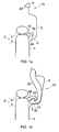
- Figure 1 a shows the curtain airbag assembly 10 in a pre-deployed state with the airbags concealed in a compartment 8.
- the compartment 8 may be provided at an upper end of the trim 4, e.g. above a window 6.
- Figure 1b shows the curtain airbag assembly 10 in a deployed state with the airbags inflated and extending over the window 6, thereby protecting occupants from side impact and preventing egress through the window.
- the airbag 20 may be activated and expelled, e.g. inflated, from the compartment 8 in a conventional manner.
- the airbags 20 comprise one or more shaped portions 22 that are shaped to complement, e.g. engage, at least an engaging portion 40 of the seat 2 when the airbag is deployed.
- the shaped portions 22 may be configured such that when the airbag 20 is deployed the shaped portions 22 engage the engaging portion 40 of the seat 2 to assist in securing the airbag in place.
- Each airbag 20 may comprise one or more shaped portions 22 for engaging with the engaging portion 40.
- a single airbag 20 may be provided for a plurality of seats 2, e.g. where the seats are arranged one behind the other.
- the airbag may be provided with a plurality of shaped portions 22, with at least one shaped portion for each seat. In either case, the airbags 20 may extend across one or more windows 6.
- the shaped portions 22 may form a receiving portion when the airbag 20 is deployed.
- the receiving portion may be configured to receive the seat engaging portion 40.
- the engaging portion 40 may be in the form of a hook 42 and the airbag shaped portions 22 may be shaped to conform to the engaging portion hook 42.
- the shaped portions 22 of the airbag may comprise an upward extending portion 23 when the airbag is deployed.
- the hook 42 may be received between the upward extending portion 23 and the remainder of the airbag 20.
- the upward extending portion 23 may be received in a recess 44 defined by the hook 42.
- the shaped portions 22 and engaging portion 40 may interlock when the airbag is deployed so that the airbag is held in place over the window 6 and egress of an occupant through the window is prevented.
- the shaped portions 22 may be provided at or towards a bottom end of the airbag 20 when deployed. Similarly, the shaped portions 22 may be provided on an inward facing side of the airbag, e.g. a side of the airbag that faces away from the window 6 and towards the seat 2, when the airbag is deployed.
- the curtain airbag assembly 10 or the seat 2 may comprise the engaging portion 40.
- the engaging portion 40 may be provided at or towards the top of a back rest 2' of the seat 2. (The seat 2 may also comprise a head rest 2".)
- the engaging portion 40 may be provided at a location above a sill 6' associated with the window 6.
- the engaging portion 40 may extend from one side of the seat 2, in particular on a side of the seat facing the adjacent window 6. Accordingly, the engaging portion 40 may extend in the direction of the window 6.
- the engaging portion 40 may also extend in a direction with a component in the upwards direction.
- the engaging portion 40 may be mounted on a seat belt guide associated with the seat 2.
- the engaging portion 40 may be integral with the seat belt guide.
- the shaped portions 22 in the deployed state may be enabled by the shape of the airbag 20 in the pre-deployed state.
- the material forming the airbag may be shaped in the pre-deployed state so as to form the shaped portions 22 when deployed.
- the airbags 20 may comprise one or more panels or layers of material. The panels may be shaped so as to form the one or more shaped portions 22.
- the panels of material may be joined together, e.g. by one or more seams. The location of the joins may assist in forming the shaped portions in the deployed state.
- the airbag 20 When the airbag 20 is deployed, the airbag may unfurl along the window 6 and a lower end of the airbag may be guided by the trim 4, e.g. the window sill 6', towards the engaging portion 40.
- the airbag 20 may unwrap along the window 6 and trim 4 so as to deliver the shaped portion 22 to the engaging portion 40.
- the trim 4 may be shaped to aid the unfurling of the airbag 20 towards the engaging portion 40.
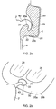
- the shaped portions 22 may then engage the engaging portion 40 to assist in securing the airbag 20 in place.
- the one or more shaped portions 22 may form an opening 24 in a surface of the airbag and the opening 24 may be configured to engage the engaging portion 40 when the airbag 20 is deployed.
- the opening 24 may extend partially from a first side 26a of the airbag to a second side 26b of the airbag. In other words, the opening 24 may not extend to the second side 26b.
- the opening 24 may or may not extend across the full width of the airbag, e.g. in the fore-aft direction.
- the opening 24 may extend from the first side 26a of the airbag to the second side 26b of the airbag, e.g. through the thickness of the airbag.
- the opening 24 may have one or more sidewalls 25 to ensure that the airbag 20 remains substantially airtight.
- the opening 24 may be provided in a substantially tubular portion 30 of the airbag 20.
- the airbag 20 may comprise one or more head protection chambers 28.
- the tubular portion 30 may surround the head protection chambers 28.
- Reinforcements, such as reinforcing stitching 32, may be provided around the opening 24 to ensure the structural integrity of the opening 24 and/or to ensure that the airbag 20 remains substantially airtight.
- the one or more airbags 20 may comprise supplementary material 50 in at least a region of the airbag adjacent to the seat 2 when the airbag is deployed.
- the supplementary material 50 may be configured such that the supplementary material may clamp the seat 2 when the airbag 20 is deployed.
- the supplementary material 50 may form the one or more shaped portions 22.
- Figure 3 shows a previously proposed airbag arrangement 120 and this is contrasted by Figure 4 , which shows an airbag arrangement according to the third example of the present disclosure with the supplementary material 50.
- Figures 3a and 3b show the previously-proposed curtain airbag arrangement 120 in a pre-deployed and deployed state respectively and Figures 4a and 4b show the airbag arrangement according to the third example of the present disclosure in the pre-deployed and deployed states respectively.
- the supplementary material 50 may be provided in a region of the airbag that is adjacent to the seat 2 when deployed.
- the supplementary material 50 may be provided adjacent to a join 52 in the airbag 20.
- the join 52 may be between first and second layers 54, 56 forming the airbag 20.
- the join 52 may be provided between neighbouring chambers 58a, 58b configured for receiving gas during deployment of the airbag.
- the join 52 may be elongate and may be orientated in a direction that substantially follows an edge of the seat back 2' when the airbag is deployed.
- the join 52 between the first and second layers 54, 56 may be formed by weaving, stitching, cross-tethering or any other joining technique.
- the supplementary material 50 may be continuous with the surrounding material of the airbag, e.g. the supplementary material and the surrounding material may be unitary.
- One or both layers 54, 56 of the airbags may comprise the supplementary material 50.
- the layer 54 adjacent to the seat 2 may be provided with the supplementary material 50.
- the layer 56 adjacent to the trim 4 may also be provided with the supplementary material 50.
- the supplementary material 50 may also be provided either side of the join 52, e.g. fore or aft of the join in the deployed state. However, as depicted the supplementary material 50 may be provided on both sides of the join 52.
- the supplementary material 50 may grip the seat back 2' when the airbag 20 is deployed.
- the lack of any supplementary material with the previously-proposed airbag arrangement does not permit the seat to be clamped by the airbag 120.
- Figure 5 shows further views of the airbag 20 according to the third example in a deployed state.
- the supplementary material 50 increases the space in which the airbag 20 expands into and permits the airbag to clamp around the seat back 2'.
- the supplementary material 50 may form the shaped portions 22 of the airbag.
- the engaging portion 40 may be a portion of the seat 2, e.g. a portion of the seat back 2'.
- the airbag 20 may comprise a web or sail 60.
- the sail 60 may comprise a layer of material that is not inflatable.
- the sail 60 may be provided between and/or below chambers 58a, 58b.
- the sail 60 may help to retain the structure of the airbag 20 when deployed.
- the one or more airbags 20 may comprise overlapping portions 34 that overlap when the airbag is deflated.
- Figures 6a and 6b show side and bottom views respectively of the airbag in the pre-deployed state
- Figures 6c and 6d show side and bottom views respectively of the airbag 20 in the deployed state.
- the overlapping portions 34 may overlap before the airbag is deployed and when the airbag is substantially flat.
- the overlapping portions 34 are formed by airbag portions 38, which are wider (in the fore-aft direction of the vehicle) at the bottom end of the airbag 20 so as to overlap.
- the airbag portions 38 may be separate airbags or they may be portions of the same airbag.
- the overlapping portions 34 may engage, e.g. clamp, either side of the seat back 2' when the airbag is deployed. It will be appreciated that the overlapping portions 34 may form the shaped portions 22 of the airbag.
- the engaging portion 40 may be a portion of the seat 2, e.g. a portion of the seat back 2'.
- the overlapping portions 34 may be formed by slits 36 in or between one or more panels making up the airbag 20.
- One or more slits 36 may extend from a lower end of the airbag 20 (when the airbag is deployed).
- a plurality of slits 36 may be provided in a single airbag 20.
- Supplementary material 50 may form the overlaps that define the overlapping portions 34.
- the airbag 20 may be positioned in the vehicle such that the slits 36 line up with the seat backs 2' when the airbag is deployed.
- the airbag 20 When the overlapping portions 34 are inflated, the airbag 20 will want to occupy the space between the overlaps. This tendency serves to clamp the airbag 20 around the seat back 2' and thus hold the airbag 20 in place.
- a curtain airbag assembly for a vehicle having one or more airbags, wherein the airbags comprise one or more shaped portions that are shaped to complement at least an engaging portion of a seat of the vehicle when the airbag is deployed, the shaped portions being configured such that when the airbag is deployed the shaped portions engage the engaging portion of the seat to assist in securing the airbag in place.
- Statement 2 The curtain airbag assembly of statement 1, wherein the shaped portions form a receiving portion when the airbag is deployed, the receiving portion being configured to receive the seat engaging portion.
- Statement 3 The curtain airbag assembly of statement 1 or 2, wherein the shaped portions form an opening in a surface of the airbag, the opening being configured to engage the engaging portion of the seat when the airbag is deployed.
- Statement 4 The curtain airbag assembly of statement 3, wherein the opening extends from a first side of the airbag to a second side of the airbag or the opening extends partially from a first side of the airbag to a second side of the airbag.
- Statement 5 The curtain airbag assembly of statement 3 or 4, wherein the opening has one or more sidewalls to ensure that the airbag remains substantially airtight.
- An engaging portion for a seat of a vehicle being configured to complement one or more shaped portions of an airbag when the airbag is deployed, the engaging portion being configured such that when the airbag is deployed the engaging portion engages the shaped portions to assist in securing the airbag in place.
- Statement 13 The engaging portion of statement 12, wherein the engaging portion comprises a hook portion configured to engage an opening formed by the one or more shaped portions.
- Statement 14 The engaging portion of statement 12 or 13, wherein the engaging portion is configured to engage the curtain airbag assembly of any of statements 1 to 11.
- Statement 15 A vehicle comprising the curtain airbag assembly of any of statements 1 to 11 and/or the engaging portion of any of statements 12 to 14.
- a method of deploying a curtain airbag assembly for a vehicle having one or more airbags, wherein the airbags comprise one or more shaped portions that are shaped to complement at least an engaging portion of a seat of the vehicle when the airbag is deployed, the method comprising deploying the airbag and engaging the engaging portion of the seat with the shaped portions to assist in securing the airbag in place.
Landscapes
- Engineering & Computer Science (AREA)
- Mechanical Engineering (AREA)
- Aviation & Aerospace Engineering (AREA)
- Transportation (AREA)
- Air Bags (AREA)
Description
- The present disclosure relates to a curtain airbag assembly and in particular to an improved curtain airbag assembly for a motor vehicle.
- It is known to provide a motor vehicle with a curtain airbag to protect an occupant of a motor vehicle from contact with a side of the motor vehicle during an accident and to prevent a body part of an occupant from passing through a window aperture during a roll-over event.
- It is further known to provide two airbags arranged in a side by side relationship each of the airbags having a straight edge that, when the airbags are deployed, forms a vertical edge that abuts the corresponding vertical edge of the adjacent airbag. The location of the join between the two airbags is normally located in front of a vertical window frame member, such as a B-post or C-post, and the join is often held together by tethers.
- It is a problem with such curtain airbag arrangements that, when forces are applied to the two airbags by the impact of one or more occupants, the two vertical edges can separate unless there are many tethers holding the two airbags in place, and the tethers hold the two airbags tightly together which is technically difficult to achieve. Any such airbag separation risks exposure of the underlying structural member which is clearly not desirable. It is a further problem with such an arrangement that, if the forces applied to one airbag are considerably larger than those applied to the other airbag, the other airbag can be dragged across potentially causing the one airbag to move into an unstable position thereby reducing its effectiveness particularly in respect of extrusion of the airbag through an adjacent window aperture.
- The present disclosure seeks to address these issues.
- According to a first aspect of the present disclosure there is provided a curtain airbag assembly for a vehicle, such as a motor vehicle, the curtain airbag assembly having one or more airbags, wherein the airbags comprise one or more shaped portions that are shaped to complement, e.g. engage, at least an engaging portion of a seat of the vehicle when the airbag is deployed, e.g. inflated. The shaped portions may be configured such that when the airbag is deployed the shaped portions engage the engaging portion of the seat to assist in securing the airbag in place.
- The shaped portions may form a receiving portion when the airbag is deployed. The receiving portion may be configured to receive the seat engaging portion.
- The shaped portions may form an opening in a surface of the airbag. The opening may be configured to engage the engaging portion of the seat when the airbag is deployed. The opening may extend from a first side of the airbag to a second side of the airbag. The opening may extend partially from a first side of the airbag to a second side of the airbag. The opening may have one or more sidewalls to ensure that the airbag remains substantially airtight.
- The shaped portions may be shaped in a pre-deployed state. The airbags may comprise one or more panels. The panels may be shaped so as to form the one or more shaped portions.
- The shaped portions may be configured to engage a hook portion provided on the seat, e.g. on the seat back. The curtain airbag assembly may comprise the engaging portion of the seat. The curtain airbag assembly may comprise the hook portion.
- One or more of the airbags may comprise supplementary material in at least a region of the airbag that may be adjacent to the seat when the airbag is deployed. One or more layers of the airbags may comprise the supplementary material. The supplementary material may be configured such that the supplementary material may clamp the seat when the airbag is deployed.
- One or more of the airbags may comprise overlapping portions that overlap when the airbag is deflated. The overlapping portions may form the shaped portions. The overlapping portions may be configured to clamp the seat when the airbag is deployed. The shaped portions may be configured to engage a back of the seat.
- The shaped portions may be provided at or towards a bottom end of the airbag when deployed.
- According to a second aspect of the present disclosure there is provided an engaging portion for a seat of a vehicle, the engaging portion being configured to complement one or more shaped portions of an airbag when the airbag is deployed, the engaging portion being configured such that when the airbag is deployed the engaging portion engages the shaped portions to assist in securing the airbag in place. A seat for a vehicle may comprise the engaging portion configured to complement one or more shaped portions of an airbag. The engaging portion may comprise a hook portion configured to engage an opening formed by the one or more shaped portions. The engaging portion may be configured to engage the above-mentioned curtain airbag assembly.
- A vehicle may comprise the above-mentioned curtain airbag assembly. A vehicle may comprise the above-mentioned engaging portion.
- According to a third aspect of the present disclosure there is provided a method of deploying a curtain airbag assembly for a vehicle, the curtain airbag assembly having one or more airbags, wherein the airbags comprise one or more shaped portions that are shaped to complement at least an engaging portion of a seat of the vehicle when the airbag is deployed, the method comprising deploying the airbag and engaging the engaging portion of the seat with the shaped portions to assist in securing the airbag in place.
- For a better understanding of the present disclosure, and to show more clearly how it may be carried into effect, reference will now be made, by way of example, to the accompanying drawings, in which:
-
Figures 1 a and 1 b show front views of a curtain airbag assembly according to a first example of the present disclosure in whichFigure 1 a shows the curtain airbag assembly in a pre-deployed state andFigure 1b shows the curtain airbag assembly in a deployed state; -
Figures 2a and 2b show a sectional front view of the curtain airbag assembly in a deployed state according to the first example of the present disclosure and a perspective view of the curtain airbag assembly in a deployed state according to a second example of the present disclosure respectively; -
Figures 3a and 3b show top views of a previously-proposed curtain airbag assembly in a pre-deployed and deployed state respectively; -
Figures 4a and 4b show top views of the curtain airbag assembly according to a third example of the present disclosure in a pre-deployed and deployed state respectively; -
Figures 5a, 5b and 5c show side, back (section A-A) and top (section B-B) views of the curtain airbag assembly according to the third example of the present disclosure in a deployed state respectively; and -
Figures 6a, 6b, 6c and 6d show side views (Figures 6a and 6c ) and bottom views (Figures 6b and 6d ) of the curtain airbag assembly according to a fourth example of the present disclosure in a pre-deployed state (Figures 6a and 6b ) and a deployed state (Figures 6c and 6d ). - With reference to
Figure 1 , the present disclosure relates to acurtain airbag assembly 10 for a vehicle, such as a motor vehicle. Thecurtain airbag assembly 10 has one ormore airbags 20. As such, the one ormore airbags 20 may form a side air curtain, which is provided between aseat 2 and aside trim 4 of the vehicle.Figure 1 a shows thecurtain airbag assembly 10 in a pre-deployed state with the airbags concealed in acompartment 8. Thecompartment 8 may be provided at an upper end of thetrim 4, e.g. above awindow 6. By contrast,Figure 1b shows thecurtain airbag assembly 10 in a deployed state with the airbags inflated and extending over thewindow 6, thereby protecting occupants from side impact and preventing egress through the window. Theairbag 20 may be activated and expelled, e.g. inflated, from thecompartment 8 in a conventional manner. - The
airbags 20 comprise one or moreshaped portions 22 that are shaped to complement, e.g. engage, at least anengaging portion 40 of theseat 2 when the airbag is deployed. Theshaped portions 22 may be configured such that when theairbag 20 is deployed theshaped portions 22 engage theengaging portion 40 of theseat 2 to assist in securing the airbag in place. - There may be one
airbag 20 perseat 2. Eachairbag 20 may comprise one or moreshaped portions 22 for engaging with theengaging portion 40. Alternatively, asingle airbag 20 may be provided for a plurality ofseats 2, e.g. where the seats are arranged one behind the other. In the case of a single airbag being provided for a plurality of seats, the airbag may be provided with a plurality ofshaped portions 22, with at least one shaped portion for each seat. In either case, theairbags 20 may extend across one ormore windows 6. - As depicted in
Figure 1b , theshaped portions 22 may form a receiving portion when theairbag 20 is deployed. The receiving portion may be configured to receive theseat engaging portion 40. By way of example, the engagingportion 40 may be in the form of ahook 42 and the airbag shapedportions 22 may be shaped to conform to the engagingportion hook 42. The shapedportions 22 of the airbag may comprise an upward extendingportion 23 when the airbag is deployed. Thehook 42 may be received between the upward extendingportion 23 and the remainder of theairbag 20. Similarly, the upward extendingportion 23 may be received in arecess 44 defined by thehook 42. The shapedportions 22 and engagingportion 40 may interlock when the airbag is deployed so that the airbag is held in place over thewindow 6 and egress of an occupant through the window is prevented. - The shaped
portions 22 may be provided at or towards a bottom end of theairbag 20 when deployed. Similarly, the shapedportions 22 may be provided on an inward facing side of the airbag, e.g. a side of the airbag that faces away from thewindow 6 and towards theseat 2, when the airbag is deployed. - The
curtain airbag assembly 10 or theseat 2 may comprise the engagingportion 40. The engagingportion 40 may be provided at or towards the top of a back rest 2' of theseat 2. (Theseat 2 may also comprise ahead rest 2".) The engagingportion 40 may be provided at a location above a sill 6' associated with thewindow 6. The engagingportion 40 may extend from one side of theseat 2, in particular on a side of the seat facing theadjacent window 6. Accordingly, the engagingportion 40 may extend in the direction of thewindow 6. The engagingportion 40 may also extend in a direction with a component in the upwards direction. - The engaging
portion 40 may be mounted on a seat belt guide associated with theseat 2. The engagingportion 40 may be integral with the seat belt guide. - It will be appreciated that the shaped
portions 22 in the deployed state may be enabled by the shape of theairbag 20 in the pre-deployed state. For example, the material forming the airbag may be shaped in the pre-deployed state so as to form the shapedportions 22 when deployed. In particular, theairbags 20 may comprise one or more panels or layers of material. The panels may be shaped so as to form the one or moreshaped portions 22. The panels of material may be joined together, e.g. by one or more seams. The location of the joins may assist in forming the shaped portions in the deployed state. - When the
airbag 20 is deployed, the airbag may unfurl along thewindow 6 and a lower end of the airbag may be guided by thetrim 4, e.g. the window sill 6', towards the engagingportion 40. In other words, theairbag 20 may unwrap along thewindow 6 and trim 4 so as to deliver the shapedportion 22 to the engagingportion 40. Thetrim 4 may be shaped to aid the unfurling of theairbag 20 towards the engagingportion 40. The shapedportions 22 may then engage the engagingportion 40 to assist in securing theairbag 20 in place. - With reference to
Figure 2 , the one or moreshaped portions 22 may form anopening 24 in a surface of the airbag and theopening 24 may be configured to engage the engagingportion 40 when theairbag 20 is deployed. As depicted inFigure 2a , in a first example of the present disclosure, theopening 24 may extend partially from afirst side 26a of the airbag to asecond side 26b of the airbag. In other words, theopening 24 may not extend to thesecond side 26b. Theopening 24 may or may not extend across the full width of the airbag, e.g. in the fore-aft direction. - However, as depicted in
Figure 2b , in a second example of the present disclosure, theopening 24 may extend from thefirst side 26a of the airbag to thesecond side 26b of the airbag, e.g. through the thickness of the airbag. In either the first or second example, theopening 24 may have one or more sidewalls 25 to ensure that theairbag 20 remains substantially airtight. - As is shown in
Figure 2b , theopening 24 may be provided in a substantiallytubular portion 30 of theairbag 20. Theairbag 20 may comprise one or morehead protection chambers 28. Thetubular portion 30 may surround thehead protection chambers 28. Reinforcements, such as reinforcingstitching 32, may be provided around theopening 24 to ensure the structural integrity of theopening 24 and/or to ensure that theairbag 20 remains substantially airtight. - With reference to
Figures 4 and5 , in a third example of the present disclosure, the one ormore airbags 20 may comprisesupplementary material 50 in at least a region of the airbag adjacent to theseat 2 when the airbag is deployed. Thesupplementary material 50 may be configured such that the supplementary material may clamp theseat 2 when theairbag 20 is deployed. Thesupplementary material 50 may form the one or moreshaped portions 22. -
Figure 3 shows a previously proposedairbag arrangement 120 and this is contrasted byFigure 4 , which shows an airbag arrangement according to the third example of the present disclosure with thesupplementary material 50. (Figures 3a and 3b show the previously-proposedcurtain airbag arrangement 120 in a pre-deployed and deployed state respectively andFigures 4a and 4b show the airbag arrangement according to the third example of the present disclosure in the pre-deployed and deployed states respectively.) - The
supplementary material 50 may be provided in a region of the airbag that is adjacent to theseat 2 when deployed. Thesupplementary material 50 may be provided adjacent to ajoin 52 in theairbag 20. Thejoin 52 may be between first andsecond layers airbag 20. Thejoin 52 may be provided betweenneighbouring chambers join 52 may be elongate and may be orientated in a direction that substantially follows an edge of the seat back 2' when the airbag is deployed. Thejoin 52 between the first andsecond layers - The
supplementary material 50 may be continuous with the surrounding material of the airbag, e.g. the supplementary material and the surrounding material may be unitary. One or bothlayers supplementary material 50. However, thelayer 54 adjacent to theseat 2 may be provided with thesupplementary material 50. Thelayer 56 adjacent to thetrim 4 may also be provided with thesupplementary material 50. Thesupplementary material 50 may also be provided either side of thejoin 52, e.g. fore or aft of the join in the deployed state. However, as depicted thesupplementary material 50 may be provided on both sides of thejoin 52. As depicted inFigure 4b , thesupplementary material 50 may grip the seat back 2' when theairbag 20 is deployed. By contrast, as shown inFigure 3b , the lack of any supplementary material with the previously-proposed airbag arrangement does not permit the seat to be clamped by theairbag 120. -
Figure 5 shows further views of theairbag 20 according to the third example in a deployed state. As is depicted, thesupplementary material 50 increases the space in which theairbag 20 expands into and permits the airbag to clamp around the seat back 2'. It will be appreciated that thesupplementary material 50 may form the shapedportions 22 of the airbag. Furthermore, the engagingportion 40 may be a portion of theseat 2, e.g. a portion of the seat back 2'. - As shown in
Figures 5a and 5b , theairbag 20 may comprise a web orsail 60. Thesail 60 may comprise a layer of material that is not inflatable. Thesail 60 may be provided between and/or belowchambers sail 60 may help to retain the structure of theairbag 20 when deployed. - With reference to
Figure 6 , in a fourth example of the present disclosure, the one ormore airbags 20 may comprise overlappingportions 34 that overlap when the airbag is deflated.Figures 6a and 6b show side and bottom views respectively of the airbag in the pre-deployed state, whereasFigures 6c and 6d show side and bottom views respectively of theairbag 20 in the deployed state. - As depicted in
Figures 6a and 6b , the overlappingportions 34 may overlap before the airbag is deployed and when the airbag is substantially flat. The overlappingportions 34 are formed byairbag portions 38, which are wider (in the fore-aft direction of the vehicle) at the bottom end of theairbag 20 so as to overlap. Theairbag portions 38 may be separate airbags or they may be portions of the same airbag. - As shown in
Figures 6c and 6d , the overlappingportions 34 may engage, e.g. clamp, either side of the seat back 2' when the airbag is deployed. It will be appreciated that the overlappingportions 34 may form the shapedportions 22 of the airbag. - Furthermore, as for the third example, the engaging
portion 40 may be a portion of theseat 2, e.g. a portion of the seat back 2'. - The overlapping
portions 34 may be formed byslits 36 in or between one or more panels making up theairbag 20. One ormore slits 36 may extend from a lower end of the airbag 20 (when the airbag is deployed). A plurality ofslits 36 may be provided in asingle airbag 20.Supplementary material 50 may form the overlaps that define the overlappingportions 34. Theairbag 20 may be positioned in the vehicle such that theslits 36 line up with the seat backs 2' when the airbag is deployed. - When the overlapping
portions 34 are inflated, theairbag 20 will want to occupy the space between the overlaps. This tendency serves to clamp theairbag 20 around the seat back 2' and thus hold theairbag 20 in place. - The present application is a divisional application of
EP14183677.5 EP14183677.5 - Statement 1. A curtain airbag assembly for a vehicle, the curtain airbag assembly having one or more airbags, wherein the airbags comprise one or more shaped portions that are shaped to complement at least an engaging portion of a seat of the vehicle when the airbag is deployed, the shaped portions being configured such that when the airbag is deployed the shaped portions engage the engaging portion of the seat to assist in securing the airbag in place.
-
Statement 2. The curtain airbag assembly of statement 1, wherein the shaped portions form a receiving portion when the airbag is deployed, the receiving portion being configured to receive the seat engaging portion. - Statement 3. The curtain airbag assembly of
statement 1 or 2, wherein the shaped portions form an opening in a surface of the airbag, the opening being configured to engage the engaging portion of the seat when the airbag is deployed. -
Statement 4. The curtain airbag assembly of statement 3, wherein the opening extends from a first side of the airbag to a second side of the airbag or the opening extends partially from a first side of the airbag to a second side of the airbag. - Statement 5. The curtain airbag assembly of
statement 3 or 4, wherein the opening has one or more sidewalls to ensure that the airbag remains substantially airtight. -
Statement 6. The curtain airbag assembly of any of the preceding statements, wherein the shaped portions are shaped in a pre-deployed state. - Statement 7. The curtain airbag assembly of any of the preceding statements, wherein the airbag comprises one or more panels, the panels being shaped so as to form the one or more shaped portions.
-
Statement 8. The curtain airbag assembly of any of the preceding statements, wherein one or more of the airbags comprise supplementary material in at least a region of the airbag adjacent to the seat when the airbag is deployed, the supplementary material being configured such that the supplementary material clamps the seat when the airbag is deployed. - Statement 9. The curtain airbag assembly of any of the preceding statements, wherein the shaped portions are configured to engage a hook portion provided on the seat and/or engage a back of the seat.
-
Statement 10. The curtain airbag assembly of any of the preceding statements, wherein one or more of the airbags comprise overlapping portions that overlap when the airbag is deflated, the overlapping portions forming the shaped portions and being configured to clamp the seat when the airbag is deployed. - Statement 11. The curtain airbag assembly of any of the preceding statements, wherein the shaped portions are provided at or towards a bottom end of the airbag when deployed.
- Statement 12. An engaging portion for a seat of a vehicle, the engaging portion being configured to complement one or more shaped portions of an airbag when the airbag is deployed, the engaging portion being configured such that when the airbag is deployed the engaging portion engages the shaped portions to assist in securing the airbag in place.
- Statement 13. The engaging portion of statement 12, wherein the engaging portion comprises a hook portion configured to engage an opening formed by the one or more shaped portions.
- Statement 14. The engaging portion of statement 12 or 13, wherein the engaging portion is configured to engage the curtain airbag assembly of any of statements 1 to 11.
- Statement 15. A vehicle comprising the curtain airbag assembly of any of statements 1 to 11 and/or the engaging portion of any of statements 12 to 14.
- Statement 16. A method of deploying a curtain airbag assembly for a vehicle, the curtain airbag assembly having one or more airbags, wherein the airbags comprise one or more shaped portions that are shaped to complement at least an engaging portion of a seat of the vehicle when the airbag is deployed, the method comprising deploying the airbag and engaging the engaging portion of the seat with the shaped portions to assist in securing the airbag in place.
- It will be appreciated by those skilled in the art that although the invention has been described by way of example with reference to one or more examples, it is not limited to the disclosed examples and that alternative examples could be constructed without departing from the scope of the invention as defined by the appended claims.
Claims (15)
- A curtain airbag assembly (10) for a vehicle, the curtain airbag assembly having one or more airbags (20), wherein the airbags comprise one or more shaped portions (22) that are shaped to complement at least an engaging portion of a seat (2) of the vehicle when the airbag is deployed, the shaped portions being configured such that when the airbag is deployed the shaped portions engage the engaging portion of the seat to assist in securing the airbag in place, wherein one or more of the airbags (20) comprise supplementary material (50) in at least a region of the airbag adjacent to the seat (2) when the airbag is deployed, the supplementary material being configured such that the supplementary material forms the shaped portions (22) and clamps the seat when the airbag is deployed.
- The curtain airbag assembly of claim 1, wherein the supplementary material (50) is provided adjacent to a join (52) in the airbag (20).
- The curtain airbag assembly of claim 2, wherein the join (52) is between first and second layers (54, 56) forming the airbag (20).
- The curtain airbag assembly of claim 2 or 3, wherein the join (52) is provided between neighbouring chambers (58a, 58b) configured for receiving gas during deployment of the airbag (20).
- The curtain airbag assembly of claim 4, further comprising a sail (60) comprising a non-inflatable layer of material provided between and/or below chambers (58a, 58b).
- The curtain airbag assembly of any of claims 2 to 5, wherein the join (52) is elongate and is orientated in a direction that substantially follows an edge of a seat back (2') of the seat when the airbag (20) is deployed.
- The curtain airbag assembly of any of the preceding claims, wherein the shaped portions (22) are shaped in a pre-deployed state.
- The curtain airbag assembly of any of the preceding claims, wherein the airbag (20) comprises one or more panels, the panels being shaped so as to form the one or more shaped portions.
- The curtain airbag assembly of any of the preceding claims, wherein one or more of the airbags (20) comprise overlapping portions (34) formed by the supplementary material (50) that overlap when the airbag (20) is deflated, the overlapping portions forming the shaped portions (22) and being configured to clamp the seat (2) when the airbag is deployed.
- The curtain airbag assembly of claim 9, wherein the overlapping portions (34) are formed by airbag portions (38) which are wider at a bottom end of the airbag so as to overlap.
- The curtain airbag assembly of claim 10, wherein the airbag portions (38) are separate airbags or portions of the same airbag.
- The curtain airbag assembly of any of claims 9 to 11, wherein the overlapping portions (34) are formed by slits (36) in or between one or more panels making up the airbag and wherein the slits are configured to line up with seat backs (2') when the airbag is deployed.
- The curtain airbag assembly of any of the preceding claims, wherein the shaped portions (22) are provided at or towards a bottom end of the airbag (20) when deployed.
- A vehicle comprising the curtain airbag assembly (10) of any of claims 1 to 13.
- A method of deploying a curtain airbag assembly (10) for a vehicle, the curtain airbag assembly having one or more airbags (20), wherein the airbags comprise one or more shaped portions (22) that are shaped to complement at least an engaging portion of a seat of the vehicle when the airbag is deployed wherein one or more of the airbags (20) comprise supplementary material (50) in at least a region of the airbag adjacent to the seat (2) when the airbag is deployed, the supplementary material being configured such that the supplementary material forms the shaped portions (22) and clamps the seat when the airbag is deployed, the method comprising deploying the airbag (20) and engaging the engaging portion of the seat with the shaped portions (22) to assist in securing the airbag in place.
Applications Claiming Priority (2)
| Application Number | Priority Date | Filing Date | Title |
|---|---|---|---|
| GB1319156.4A GB2519784A (en) | 2013-10-30 | 2013-10-30 | An Airbag Assembly |
| EP14183677.5A EP2868535B1 (en) | 2013-10-30 | 2014-09-05 | An airbag assembly |
Related Parent Applications (2)
| Application Number | Title | Priority Date | Filing Date |
|---|---|---|---|
| EP14183677.5A Division-Into EP2868535B1 (en) | 2013-10-30 | 2014-09-05 | An airbag assembly |
| EP14183677.5A Division EP2868535B1 (en) | 2013-10-30 | 2014-09-05 | An airbag assembly |
Publications (2)
| Publication Number | Publication Date |
|---|---|
| EP3135542A1 true EP3135542A1 (en) | 2017-03-01 |
| EP3135542B1 EP3135542B1 (en) | 2018-03-14 |
Family
ID=49767381
Family Applications (2)
| Application Number | Title | Priority Date | Filing Date |
|---|---|---|---|
| EP14183677.5A Active EP2868535B1 (en) | 2013-10-30 | 2014-09-05 | An airbag assembly |
| EP16192067.3A Active EP3135542B1 (en) | 2013-10-30 | 2014-09-05 | An airbag assembly |
Family Applications Before (1)
| Application Number | Title | Priority Date | Filing Date |
|---|---|---|---|
| EP14183677.5A Active EP2868535B1 (en) | 2013-10-30 | 2014-09-05 | An airbag assembly |
Country Status (6)
| Country | Link |
|---|---|
| US (1) | US9156429B2 (en) |
| EP (2) | EP2868535B1 (en) |
| CN (1) | CN204236412U (en) |
| ES (1) | ES2635128T3 (en) |
| GB (1) | GB2519784A (en) |
| RU (1) | RU2014142242A (en) |
Families Citing this family (4)
| Publication number | Priority date | Publication date | Assignee | Title |
|---|---|---|---|---|
| US20160082917A1 (en) * | 2014-09-22 | 2016-03-24 | Nissan North America, Inc. | Magnetic retention assembly for a curtain airbag |
| JP6537197B2 (en) * | 2017-03-31 | 2019-07-03 | 株式会社Subaru | Curtain airbag |
| FR3123855A1 (en) * | 2021-06-10 | 2022-12-16 | Psa Automobiles Sa | Motor vehicle with at least three rows of seats and incorporating curtain-type side airbags |
| JP7746907B2 (en) * | 2022-04-12 | 2025-10-01 | トヨタ自動車株式会社 | Vehicle side structure |
Citations (3)
| Publication number | Priority date | Publication date | Assignee | Title |
|---|---|---|---|---|
| JP2011111067A (en) * | 2009-11-27 | 2011-06-09 | Nippon Plast Co Ltd | Side air bag device |
| GB2482394A (en) * | 2010-07-29 | 2012-02-01 | Ford Global Tech Llc | A curtain airbag for a motor vehicle |
| DE102012023776A1 (en) * | 2012-12-05 | 2014-06-05 | GM Global Technology Operations LLC (n. d. Ges. d. Staates Delaware) | side airbags |
Family Cites Families (9)
| Publication number | Priority date | Publication date | Assignee | Title |
|---|---|---|---|---|
| JP3161820B2 (en) * | 1992-06-17 | 2001-04-25 | マツダ株式会社 | Automotive airbag equipment |
| US5636862A (en) * | 1995-09-07 | 1997-06-10 | General Motors Corporation | Air bag assembly with tether |
| US20020171233A1 (en) * | 2001-05-18 | 2002-11-21 | Grace Gregory B. | System and method for vehicle occupant protection |
| JP3986913B2 (en) * | 2002-07-17 | 2007-10-03 | 本田技研工業株式会社 | Side airbag device |
| US7641233B2 (en) * | 2004-02-05 | 2010-01-05 | Autoliv Development Ab | Occupant restraint device and occupant restraint system |
| US20060012155A1 (en) * | 2004-07-01 | 2006-01-19 | Ford Global Technologies, Llc | Vehicle side airbag apparatus and seat containing same |
| US7240915B2 (en) * | 2004-12-03 | 2007-07-10 | Ford Global Technologies, Llc | Vehicle seating system with airbag-based occupant reaction surface |
| DE102006061968A1 (en) * | 2006-12-21 | 2008-07-03 | Autoliv Development Ab | Curtain airbag |
| DE102009033181B3 (en) * | 2009-07-13 | 2010-12-30 | Autoliv Development Ab | Vehicle seat, side airbag device and safety device |
-
2013
- 2013-10-30 GB GB1319156.4A patent/GB2519784A/en not_active Withdrawn
-
2014
- 2014-09-05 EP EP14183677.5A patent/EP2868535B1/en active Active
- 2014-09-05 ES ES14183677.5T patent/ES2635128T3/en active Active
- 2014-09-05 EP EP16192067.3A patent/EP3135542B1/en active Active
- 2014-10-20 RU RU2014142242A patent/RU2014142242A/en not_active Application Discontinuation
- 2014-10-29 CN CN201420638025.XU patent/CN204236412U/en not_active Expired - Fee Related
- 2014-10-30 US US14/528,779 patent/US9156429B2/en active Active
Patent Citations (3)
| Publication number | Priority date | Publication date | Assignee | Title |
|---|---|---|---|---|
| JP2011111067A (en) * | 2009-11-27 | 2011-06-09 | Nippon Plast Co Ltd | Side air bag device |
| GB2482394A (en) * | 2010-07-29 | 2012-02-01 | Ford Global Tech Llc | A curtain airbag for a motor vehicle |
| DE102012023776A1 (en) * | 2012-12-05 | 2014-06-05 | GM Global Technology Operations LLC (n. d. Ges. d. Staates Delaware) | side airbags |
Also Published As
| Publication number | Publication date |
|---|---|
| GB2519784A (en) | 2015-05-06 |
| US20150158451A1 (en) | 2015-06-11 |
| RU2014142242A3 (en) | 2018-05-22 |
| CN204236412U (en) | 2015-04-01 |
| EP2868535A1 (en) | 2015-05-06 |
| ES2635128T3 (en) | 2017-10-02 |
| GB201319156D0 (en) | 2013-12-11 |
| EP2868535B1 (en) | 2017-04-26 |
| US9156429B2 (en) | 2015-10-13 |
| RU2014142242A (en) | 2016-05-20 |
| EP3135542B1 (en) | 2018-03-14 |
Similar Documents
| Publication | Publication Date | Title |
|---|---|---|
| EP2957467B1 (en) | Curtain airbag for vertical and angular motion of occupant in rollover | |
| JP6734880B2 (en) | Cost-effective use of integrally molded woven fabrics for curtain airbags | |
| US8967660B2 (en) | Vehicle curtain airbag device | |
| EP1291248B1 (en) | Protective cushion for protection of vehicle occupant's head | |
| US9771046B2 (en) | Curtain airbag apparatus | |
| US9776593B2 (en) | Curtain airbag apparatus | |
| US9669790B2 (en) | Roof headliner structure in which curtain airbag for vehicle is housed | |
| US9925949B2 (en) | Airbag module with internal frangible seam | |
| US9511737B2 (en) | Curtain airbag apparatus | |
| KR102157025B1 (en) | Cushion of curtain air bag device | |
| US11260821B2 (en) | Airbag mounting tab assembly | |
| EP3135542B1 (en) | An airbag assembly | |
| US7556286B2 (en) | Extended inflatable coverage of inflatable curtains | |
| JP5623526B2 (en) | Curtain airbag device for vehicle | |
| CN107618474A (en) | Side curtain air bag device | |
| US9145103B2 (en) | Head-protecting airbag device | |
| JP5071183B2 (en) | Side airbag for vehicle seat | |
| US9845066B2 (en) | Side curtain airbag assembly for a motor vehicle | |
| EP2910434B1 (en) | Mounting envelope | |
| US20150054262A1 (en) | Airbag device for vehicle | |
| JP2010083216A (en) | Interior structure of vehicle equipped with curtain airbag | |
| JP7524740B2 (en) | Partition device for vehicles | |
| JP7189497B2 (en) | Vehicle upper interior structure | |
| US20050263995A1 (en) | Airbag apparatus and method of manufacturing airbag | |
| JP5961093B2 (en) | Curtain airbag device for vehicle |
Legal Events
| Date | Code | Title | Description |
|---|---|---|---|
| PUAI | Public reference made under article 153(3) epc to a published international application that has entered the european phase |
Free format text: ORIGINAL CODE: 0009012 |
|
| STAA | Information on the status of an ep patent application or granted ep patent |
Free format text: STATUS: REQUEST FOR EXAMINATION WAS MADE |
|
| 17P | Request for examination filed |
Effective date: 20161223 |
|
| AC | Divisional application: reference to earlier application |
Ref document number: 2868535 Country of ref document: EP Kind code of ref document: P |
|
| AK | Designated contracting states |
Kind code of ref document: A1 Designated state(s): AL AT BE BG CH CY CZ DE DK EE ES FI FR GB GR HR HU IE IS IT LI LT LU LV MC MK MT NL NO PL PT RO RS SE SI SK SM TR |
|
| GRAP | Despatch of communication of intention to grant a patent |
Free format text: ORIGINAL CODE: EPIDOSNIGR1 |
|
| STAA | Information on the status of an ep patent application or granted ep patent |
Free format text: STATUS: GRANT OF PATENT IS INTENDED |
|
| INTG | Intention to grant announced |
Effective date: 20170927 |
|
| GRAS | Grant fee paid |
Free format text: ORIGINAL CODE: EPIDOSNIGR3 |
|
| GRAA | (expected) grant |
Free format text: ORIGINAL CODE: 0009210 |
|
| STAA | Information on the status of an ep patent application or granted ep patent |
Free format text: STATUS: THE PATENT HAS BEEN GRANTED |
|
| AC | Divisional application: reference to earlier application |
Ref document number: 2868535 Country of ref document: EP Kind code of ref document: P |
|
| AK | Designated contracting states |
Kind code of ref document: B1 Designated state(s): AL AT BE BG CH CY CZ DE DK EE ES FI FR GB GR HR HU IE IS IT LI LT LU LV MC MK MT NL NO PL PT RO RS SE SI SK SM TR |
|
| REG | Reference to a national code |
Ref country code: GB Ref legal event code: FG4D |
|
| REG | Reference to a national code |
Ref country code: CH Ref legal event code: EP Ref country code: AT Ref legal event code: REF Ref document number: 978550 Country of ref document: AT Kind code of ref document: T Effective date: 20180315 |
|
| REG | Reference to a national code |
Ref country code: IE Ref legal event code: FG4D |
|
| REG | Reference to a national code |
Ref country code: DE Ref legal event code: R096 Ref document number: 602014022481 Country of ref document: DE |
|
| REG | Reference to a national code |
Ref country code: NL Ref legal event code: MP Effective date: 20180314 |
|
| REG | Reference to a national code |
Ref country code: LT Ref legal event code: MG4D |
|
| PG25 | Lapsed in a contracting state [announced via postgrant information from national office to epo] |
Ref country code: LT Free format text: LAPSE BECAUSE OF FAILURE TO SUBMIT A TRANSLATION OF THE DESCRIPTION OR TO PAY THE FEE WITHIN THE PRESCRIBED TIME-LIMIT Effective date: 20180314 Ref country code: HR Free format text: LAPSE BECAUSE OF FAILURE TO SUBMIT A TRANSLATION OF THE DESCRIPTION OR TO PAY THE FEE WITHIN THE PRESCRIBED TIME-LIMIT Effective date: 20180314 Ref country code: NO Free format text: LAPSE BECAUSE OF FAILURE TO SUBMIT A TRANSLATION OF THE DESCRIPTION OR TO PAY THE FEE WITHIN THE PRESCRIBED TIME-LIMIT Effective date: 20180614 Ref country code: CY Free format text: LAPSE BECAUSE OF FAILURE TO SUBMIT A TRANSLATION OF THE DESCRIPTION OR TO PAY THE FEE WITHIN THE PRESCRIBED TIME-LIMIT Effective date: 20180314 Ref country code: FI Free format text: LAPSE BECAUSE OF FAILURE TO SUBMIT A TRANSLATION OF THE DESCRIPTION OR TO PAY THE FEE WITHIN THE PRESCRIBED TIME-LIMIT Effective date: 20180314 |
|
| REG | Reference to a national code |
Ref country code: AT Ref legal event code: MK05 Ref document number: 978550 Country of ref document: AT Kind code of ref document: T Effective date: 20180314 |
|
| PG25 | Lapsed in a contracting state [announced via postgrant information from national office to epo] |
Ref country code: RS Free format text: LAPSE BECAUSE OF FAILURE TO SUBMIT A TRANSLATION OF THE DESCRIPTION OR TO PAY THE FEE WITHIN THE PRESCRIBED TIME-LIMIT Effective date: 20180314 Ref country code: SE Free format text: LAPSE BECAUSE OF FAILURE TO SUBMIT A TRANSLATION OF THE DESCRIPTION OR TO PAY THE FEE WITHIN THE PRESCRIBED TIME-LIMIT Effective date: 20180314 Ref country code: LV Free format text: LAPSE BECAUSE OF FAILURE TO SUBMIT A TRANSLATION OF THE DESCRIPTION OR TO PAY THE FEE WITHIN THE PRESCRIBED TIME-LIMIT Effective date: 20180314 Ref country code: GR Free format text: LAPSE BECAUSE OF FAILURE TO SUBMIT A TRANSLATION OF THE DESCRIPTION OR TO PAY THE FEE WITHIN THE PRESCRIBED TIME-LIMIT Effective date: 20180615 Ref country code: BG Free format text: LAPSE BECAUSE OF FAILURE TO SUBMIT A TRANSLATION OF THE DESCRIPTION OR TO PAY THE FEE WITHIN THE PRESCRIBED TIME-LIMIT Effective date: 20180614 |
|
| PG25 | Lapsed in a contracting state [announced via postgrant information from national office to epo] |
Ref country code: ES Free format text: LAPSE BECAUSE OF FAILURE TO SUBMIT A TRANSLATION OF THE DESCRIPTION OR TO PAY THE FEE WITHIN THE PRESCRIBED TIME-LIMIT Effective date: 20180314 Ref country code: PL Free format text: LAPSE BECAUSE OF FAILURE TO SUBMIT A TRANSLATION OF THE DESCRIPTION OR TO PAY THE FEE WITHIN THE PRESCRIBED TIME-LIMIT Effective date: 20180314 Ref country code: AL Free format text: LAPSE BECAUSE OF FAILURE TO SUBMIT A TRANSLATION OF THE DESCRIPTION OR TO PAY THE FEE WITHIN THE PRESCRIBED TIME-LIMIT Effective date: 20180314 Ref country code: IT Free format text: LAPSE BECAUSE OF FAILURE TO SUBMIT A TRANSLATION OF THE DESCRIPTION OR TO PAY THE FEE WITHIN THE PRESCRIBED TIME-LIMIT Effective date: 20180314 Ref country code: NL Free format text: LAPSE BECAUSE OF FAILURE TO SUBMIT A TRANSLATION OF THE DESCRIPTION OR TO PAY THE FEE WITHIN THE PRESCRIBED TIME-LIMIT Effective date: 20180314 Ref country code: EE Free format text: LAPSE BECAUSE OF FAILURE TO SUBMIT A TRANSLATION OF THE DESCRIPTION OR TO PAY THE FEE WITHIN THE PRESCRIBED TIME-LIMIT Effective date: 20180314 Ref country code: RO Free format text: LAPSE BECAUSE OF FAILURE TO SUBMIT A TRANSLATION OF THE DESCRIPTION OR TO PAY THE FEE WITHIN THE PRESCRIBED TIME-LIMIT Effective date: 20180314 |
|
| PG25 | Lapsed in a contracting state [announced via postgrant information from national office to epo] |
Ref country code: AT Free format text: LAPSE BECAUSE OF FAILURE TO SUBMIT A TRANSLATION OF THE DESCRIPTION OR TO PAY THE FEE WITHIN THE PRESCRIBED TIME-LIMIT Effective date: 20180314 Ref country code: SM Free format text: LAPSE BECAUSE OF FAILURE TO SUBMIT A TRANSLATION OF THE DESCRIPTION OR TO PAY THE FEE WITHIN THE PRESCRIBED TIME-LIMIT Effective date: 20180314 Ref country code: CZ Free format text: LAPSE BECAUSE OF FAILURE TO SUBMIT A TRANSLATION OF THE DESCRIPTION OR TO PAY THE FEE WITHIN THE PRESCRIBED TIME-LIMIT Effective date: 20180314 Ref country code: SK Free format text: LAPSE BECAUSE OF FAILURE TO SUBMIT A TRANSLATION OF THE DESCRIPTION OR TO PAY THE FEE WITHIN THE PRESCRIBED TIME-LIMIT Effective date: 20180314 |
|
| REG | Reference to a national code |
Ref country code: DE Ref legal event code: R097 Ref document number: 602014022481 Country of ref document: DE |
|
| PG25 | Lapsed in a contracting state [announced via postgrant information from national office to epo] |
Ref country code: PT Free format text: LAPSE BECAUSE OF FAILURE TO SUBMIT A TRANSLATION OF THE DESCRIPTION OR TO PAY THE FEE WITHIN THE PRESCRIBED TIME-LIMIT Effective date: 20180716 |
|
| PLBE | No opposition filed within time limit |
Free format text: ORIGINAL CODE: 0009261 |
|
| STAA | Information on the status of an ep patent application or granted ep patent |
Free format text: STATUS: NO OPPOSITION FILED WITHIN TIME LIMIT |
|
| PG25 | Lapsed in a contracting state [announced via postgrant information from national office to epo] |
Ref country code: DK Free format text: LAPSE BECAUSE OF FAILURE TO SUBMIT A TRANSLATION OF THE DESCRIPTION OR TO PAY THE FEE WITHIN THE PRESCRIBED TIME-LIMIT Effective date: 20180314 |
|
| 26N | No opposition filed |
Effective date: 20181217 |
|
| PG25 | Lapsed in a contracting state [announced via postgrant information from national office to epo] |
Ref country code: SI Free format text: LAPSE BECAUSE OF FAILURE TO SUBMIT A TRANSLATION OF THE DESCRIPTION OR TO PAY THE FEE WITHIN THE PRESCRIBED TIME-LIMIT Effective date: 20180314 |
|
| PG25 | Lapsed in a contracting state [announced via postgrant information from national office to epo] |
Ref country code: MC Free format text: LAPSE BECAUSE OF FAILURE TO SUBMIT A TRANSLATION OF THE DESCRIPTION OR TO PAY THE FEE WITHIN THE PRESCRIBED TIME-LIMIT Effective date: 20180314 |
|
| REG | Reference to a national code |
Ref country code: CH Ref legal event code: PL |
|
| GBPC | Gb: european patent ceased through non-payment of renewal fee |
Effective date: 20180905 |
|
| REG | Reference to a national code |
Ref country code: BE Ref legal event code: MM Effective date: 20180930 |
|
| REG | Reference to a national code |
Ref country code: IE Ref legal event code: MM4A |
|
| PG25 | Lapsed in a contracting state [announced via postgrant information from national office to epo] |
Ref country code: LU Free format text: LAPSE BECAUSE OF NON-PAYMENT OF DUE FEES Effective date: 20180905 |
|
| PG25 | Lapsed in a contracting state [announced via postgrant information from national office to epo] |
Ref country code: IE Free format text: LAPSE BECAUSE OF NON-PAYMENT OF DUE FEES Effective date: 20180905 |
|
| PG25 | Lapsed in a contracting state [announced via postgrant information from national office to epo] |
Ref country code: BE Free format text: LAPSE BECAUSE OF NON-PAYMENT OF DUE FEES Effective date: 20180930 Ref country code: CH Free format text: LAPSE BECAUSE OF NON-PAYMENT OF DUE FEES Effective date: 20180930 Ref country code: LI Free format text: LAPSE BECAUSE OF NON-PAYMENT OF DUE FEES Effective date: 20180930 Ref country code: FR Free format text: LAPSE BECAUSE OF NON-PAYMENT OF DUE FEES Effective date: 20180930 |
|
| PG25 | Lapsed in a contracting state [announced via postgrant information from national office to epo] |
Ref country code: GB Free format text: LAPSE BECAUSE OF NON-PAYMENT OF DUE FEES Effective date: 20180905 |
|
| PG25 | Lapsed in a contracting state [announced via postgrant information from national office to epo] |
Ref country code: MT Free format text: LAPSE BECAUSE OF NON-PAYMENT OF DUE FEES Effective date: 20180905 |
|
| PG25 | Lapsed in a contracting state [announced via postgrant information from national office to epo] |
Ref country code: HU Free format text: LAPSE BECAUSE OF FAILURE TO SUBMIT A TRANSLATION OF THE DESCRIPTION OR TO PAY THE FEE WITHIN THE PRESCRIBED TIME-LIMIT; INVALID AB INITIO Effective date: 20140905 Ref country code: MK Free format text: LAPSE BECAUSE OF NON-PAYMENT OF DUE FEES Effective date: 20180314 |
|
| PG25 | Lapsed in a contracting state [announced via postgrant information from national office to epo] |
Ref country code: IS Free format text: LAPSE BECAUSE OF FAILURE TO SUBMIT A TRANSLATION OF THE DESCRIPTION OR TO PAY THE FEE WITHIN THE PRESCRIBED TIME-LIMIT Effective date: 20180714 |
|
| REG | Reference to a national code |
Ref country code: DE Ref legal event code: R082 Ref document number: 602014022481 Country of ref document: DE Representative=s name: HL KEMPNER PATENTANWAELTE, SOLICITORS (ENGLAND, DE Ref country code: DE Ref legal event code: R082 Ref document number: 602014022481 Country of ref document: DE Representative=s name: HL KEMPNER PATENTANWALT, RECHTSANWALT, SOLICIT, DE Ref country code: DE Ref legal event code: R082 Ref document number: 602014022481 Country of ref document: DE Representative=s name: HL KEMPNER PARTG MBB, DE |
|
| REG | Reference to a national code |
Ref country code: DE Ref legal event code: R084 Ref document number: 602014022481 Country of ref document: DE |
|
| P01 | Opt-out of the competence of the unified patent court (upc) registered |
Effective date: 20230620 |
|
| PG25 | Lapsed in a contracting state [announced via postgrant information from national office to epo] |
Ref country code: TR Free format text: LAPSE BECAUSE OF NON-PAYMENT OF DUE FEES Effective date: 20180905 |
|
| PGFP | Annual fee paid to national office [announced via postgrant information from national office to epo] |
Ref country code: DE Payment date: 20250808 Year of fee payment: 12 |