EP3135086B2 - Appareil de travail des sols et procede de production d'une carte pedologique comprenant un tel appareil de travail des sols - Google Patents
Appareil de travail des sols et procede de production d'une carte pedologique comprenant un tel appareil de travail des sols Download PDFInfo
- Publication number
- EP3135086B2 EP3135086B2 EP16401040.7A EP16401040A EP3135086B2 EP 3135086 B2 EP3135086 B2 EP 3135086B2 EP 16401040 A EP16401040 A EP 16401040A EP 3135086 B2 EP3135086 B2 EP 3135086B2
- Authority
- EP
- European Patent Office
- Prior art keywords
- soil
- cultivating
- gps
- tool
- measuring device
- Prior art date
- Legal status (The legal status is an assumption and is not a legal conclusion. Google has not performed a legal analysis and makes no representation as to the accuracy of the status listed.)
- Active
Links
Images


Classifications
-
- A—HUMAN NECESSITIES
- A01—AGRICULTURE; FORESTRY; ANIMAL HUSBANDRY; HUNTING; TRAPPING; FISHING
- A01B—SOIL WORKING IN AGRICULTURE OR FORESTRY; PARTS, DETAILS, OR ACCESSORIES OF AGRICULTURAL MACHINES OR IMPLEMENTS, IN GENERAL
- A01B79/00—Methods for working soil
- A01B79/005—Precision agriculture
-
- A—HUMAN NECESSITIES
- A01—AGRICULTURE; FORESTRY; ANIMAL HUSBANDRY; HUNTING; TRAPPING; FISHING
- A01B—SOIL WORKING IN AGRICULTURE OR FORESTRY; PARTS, DETAILS, OR ACCESSORIES OF AGRICULTURAL MACHINES OR IMPLEMENTS, IN GENERAL
- A01B61/00—Devices for, or parts of, agricultural machines or implements for preventing overstrain
Definitions
- the invention relates to a soil cultivation device according to the preamble of patent claim 1 and a method for creating a soil map with such a soil cultivation device.
- a soil cultivation device is already known in which an overload protection device for the soil cultivation tool has a sensor for registering the relative position of the soil cultivation tool, with a pressure control being in operative connection with the sensor and a microprocessor being present which ensures that the relative movements of the soil cultivation tool are minimized Reaction to different ground resistances is achievable.
- the tillage tool disclosed in this publication is a plow which is designed to be pivotable about a joint against a prestressing force generated by a hydraulic cylinder, so that the tillage tool has a uniform working position under normal soil conditions.
- the DE 42 32 067 C2 describes an overload protection device that automatically adapts to the respective soil conditions, whereby a certain degree of flexibility of the soil cultivation tool is quite permissible.
- a pressure sensor or a position sensor is used as the sensor.
- a sensor which is also referred to as a detector, measured variable recorder or measuring probe, is quite generally a technical component that can detect certain physical or chemical properties and / or the material nature of its environment qualitatively or quantitatively as a measured variable. These variables are converted into an electrical signal that can be processed further.
- the sensor is thus defined as that part of a measuring device that responds directly to a measured variable. This makes the sensor the first element in a measuring chain.
- the EP 0 749 677 B1 a method for determining data on the condition of an agricultural area, in which the required power requirement of a soil cultivation device is recorded at different points in time and is stored in a memory unit in connection with the respective location of the soil cultivation device.
- the power requirement can be determined by recording the drive and / or tractive power of the soil cultivation device or by determining the penetration depth or speed of the soil cultivation tool.
- the determined data are supplemented and / or updated by new measurements at intervals.
- a DGPS system by means of satellite navigation is used to determine the location of the soil cultivation device.
- GPS global positioning system
- the determined data are used in the solution according to the EP 0 749 677 B1 transmitted via suitable data lines to a terminal that has the memory unit.
- the recorded data is also assigned to the respective location. This type of data acquisition is intended to control or regulate the cultivation of the soil in the following year or it is possible to adapt a sowing that follows plowing to the soil conditions.
- the determination of the power requirement of the soil cultivation device leads to a relatively imprecise recording of the data of the soil area. This is due to the fact that when measuring the drive power, for example, values are also included in the assessment that are exclusively caused by the driving behavior of the driver, which can lead to misinterpretations.
- the method presented in this publication is also relatively imprecise because only the position of the soil cultivation device is determined, which corresponds to a relatively rough measurement.
- the invention is based on the object of providing a soil cultivation device which allows the soil to be cultivated to be mapped with the greatest possible accuracy.
- a procedure must be specified with which the data required and stored for this can be used.
- the object is achieved by a soil cultivation device according to claim 1.
- the means for data exchange with a global position detection system is to be understood as a transceiver system for GPS signals, which can be, for example, a navigation device whose signals are not output via voice control, but as a measurement signal in the sense of the invention get saved.
- GPS global position detection system
- the main advantage of the invention can be seen in the fact that sensors used for the measurement are arranged directly on several or on each soil cultivation tool and not, as is the case with the previously described, known solutions, on the soil cultivation device. Consequently, the idea of the solution is to provide such a sensor as possible on a large number or even on each soil cultivation tool.
- the acquisition of the measurement signals originating from the sensors, their storage in the storage unit and their merging with the GPS data consequently enables very precise, detailed mapping of the soil.
- the relative positions of the individual soil cultivation tools in relation to the GPS antenna are determined once. If the GPS antenna is on the soil cultivation device, these relative positions can also already be stored in a control unit. The determination of the relative positions of the soil cultivation tool and GPS antenna leads to a particularly precise mapping of the cultivated area.
- This mapping also makes it possible to divide the soil into areas that are easy, moderate or difficult to work with.
- the solution presented enables stones or other obstacles in the ground to be precisely positioned, so that damage to the soil cultivation tool can be effectively avoided because, for example, in the following year, the soil cultivation tool was lifted before the obstacle in the ground was reached and thus out of the Hazardous area can be removed.
- the measurement signals detected by the sensors of a force acting on the soil cultivation tool preferably measured on the soil cultivation tool or on a clamping device, and / or an acceleration and / or a speed and / or a force from the soil cultivation tool or the The distance covered by the clamping device.
- sensors are, for example, mechanical, resistive, piezoelectric, capacitive, inductive, optical or magnetic sensors.
- a manometer is an example of a mechanical sensor.
- a resistive sensor whose change in resistance can be detected is, for example, a strain gauge.
- a strain gauge When measuring with a strain gauge, this is attached directly to the soil cultivation tool or to the clamping means or integrated into it, the deformation occurring due to the action of force being recorded. As a result, the electrical resistance of the strain gauge changes with its expansion, which can be converted into an electrical voltage. This electrical voltage and thus the change in strain can be recorded and, based on the elastic properties of the component provided with the strain gauge, can be converted into a force measurement value.
- piezoceramic element as a sensor, however, the effect of the force creates a charge distribution that is proportional to the force introduced.
- pressure or shear forces can be measured. The latter can also be detected, for example, with a shear screw attached to the soil cultivation tool. Tensile forces can only be measured with pre-tension.
- Piezoelectric force transducers are usually designed to be very rigid and are also suitable for measuring highly dynamic forces (up to 60 kHz depending on the design).
- an acceleration sensor is a sensor that measures acceleration. This is mostly done by determining the inertial force acting on a test mass. It can thus be determined, for example, whether an increase or decrease in speed is taking place.
- a displacement sensor is used to measure the distance between an object and a reference point or changes in length. The change in the path is converted into a standard signal or transmitted to the control unit. Other terms for this are displacement measurement system, displacement transducer, distance sensor, position sensor or distance sensor.
- Optical sensors are based on the influence of visible or invisible light, for example in the infrared range, the change of which is converted into an electrical voltage, which in turn can be detected.
- each measurement signal recorded by the sensors is assigned to a corresponding GPS signal and stored in the memory unit in a reproducible manner.
- the corresponding GPS signal is first recorded and compared with a value for the resistance in the floor stored in the memory unit, so that starting from this position always exactly the one another correlating values of the background are available. If such an assignment and reproducibility of the signals were not given, the soil would always have to be worked on from the same starting point. This is not required by the invention.
- the energy required for the measuring process by the sensor is obtained by a generator responsible for this by means of energy harvesting, preferably from vibration energy and / or thermal energy and / or solar energy.
- energy harvesting is the general term used to describe the production of small amounts of electrical energy from sources such as ambient temperature, vibrations or air currents for mobile devices with low power.
- the structures used for this are also known as nanogenerators.
- This method can avoid restrictions caused by wired power supply or batteries.
- one or more generators on the soil cultivation device can be used to generate the energy independently, that is, independently of the towing vehicle. It is therefore within the meaning of the invention that a detailed map of the condition of the cultivated area can be created by means of the soil cultivation device according to the invention, although no wired line to the towing vehicle has to be kept for data transmission and energy transmission.
- the soil cultivation device can be, for example, a plow or cultivator.
- the tillage tools of these tillage devices are very heavily loaded during tillage and therefore require a solution as to how they can be protected from damage.
- the particular advantage of this method is the periodic repetition, the time interval preferably being adjustable so that the accuracy can be increased by reducing the time interval between two measurements.
- the recorded data from the individual sensors are then recorded together with the respective position signal within the storage unit and are therefore available for processing the soil at a later point in time.
- the measurement signals are only recorded and stored if the force and / or the torque and / or the pressure respectively acting on the soil cultivation tool exceeds a threshold value. In this way it can be achieved that only those measured values are recorded that potentially indicate a destructive effect on the soil cultivation tool. In this way, a map can be created which shows the position of obstacles in the ground.
- a matrix of the worked soil can be created in the sense of a map, which not only shows the different soil conditions, but also obstacles within the soil. Consequently, according to one embodiment of the method for determining the condition of the soil by means of the position signal and the measurement signal assigned to it, a cartographic representation of the worked soil is created and stored within the storage unit or with the aid of the storage unit.
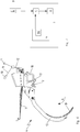
- the Fig. 1 shows, using the example of a cultivator, a soil cultivation device 1 which, in the example shown, is pulled by a towing vehicle 13.
- a tractor is used as the towing vehicle 13.
- the soil cultivation device 1 consists essentially of a frame 14 with a roller 16 at its end opposite the towing vehicle 13.
- the special feature according to the invention that the soil cultivation device 1 has a measuring device 5, which has a sensor 7 or 8 arranged on the soil cultivation tool 4, is explained below in connection with the description of FIG Figures 2 to 7 explained in more detail.
- the Fig. 1 shows, using the example of a cultivator, a soil cultivation device 1 which, in the example shown, is pulled by a towing vehicle 13.
- a tractor is used as the towing vehicle 13.
- the soil cultivation device 1 consists essentially of a frame 14 with a roller 16 at its end opposite the towing vehicle 13.
- FIG. 1 shows a part of a measuring device 5 which is embodied as a display and which visualizes the course of the measuring process for the driver of the towing vehicle 13.
- a measuring device 5 which is embodied as a display and which visualizes the course of the measuring process for the driver of the towing vehicle 13.
- the Fig. 1 Two satellites are indicated, which are components of a global position detection system (GPS) 9.
- GPS global position detection system
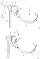
- a tool arrangement of a cultivator is shown as an example of a soil cultivation tool 4, at the lower end of which a cultivator coulter 19 is designed as a sharp-edged tip that penetrates the soil.
- the coulter support 15 is received in a flange 17 so as to be pivotable about a joint 2 and is fastened as a structural unit to the underside of the soil cultivation device 1 by means of the fastening clip 18, as described in connection with the description of FIG Fig. 1 has already been explained.
- the flange 17 of the in Fig. 2 The soil cultivation tool 4 shown also accommodates a tensioning means 3 which, in the example shown, is a tension spring.
- This tensioning means 3 acts on the coulter carrier 15 with a prestressing force which is sufficient to carry out normal tillage without the coulter carrier 15 deviating, that is to say without pivoting about the joint 2.
- the clamping means 3 is able to produce a To enable evasive movement of the coulter support 15 around the joint 2. Normally, the coulter support 15 only gives way when it comes into direct contact with a hardened section of the ground or with a stone during the cultivation of the soil.
- a sensor 7 is arranged, which in the example shown is a strain gauge.
- the deformation of the soil cultivation tool 4 caused by the action of force and the associated expansion of the strain gauge lead to a change in the electrical resistance.
- the conversion into an electrical voltage enables the conversion into a force measurement value, which is stored in a memory unit 6 and is thus available again at any time for later use.
- the acquisition of the position of the soil cultivation tool 4 via a GPS 9 and its assignment to the measured value acquired by the sensor 7 for this position value allows a very exact cartography of the cultivated soil.
- the first acceleration sensor 8 is used to generate a reference signal
- the second acceleration sensor 7 is used to record the acceleration of the coulter carrier 15 permanently and at the same time as the position signal recorded by the GPS 9. It it may be sufficient here to attach the first acceleration sensor 8 only at one point on the soil cultivating machine and to use its signal as a reference for all second acceleration sensors 7. Since all shares are articulated equally to the rigid frame, it should be sufficient to use the signal from this one sensor 8 as a reference.
- first sensors 8 can alternatively also be attached to several or all of the flanges 17, for example. As a result, every change in the position of the coulter carrier 15 can be determined very precisely by determining an increase or decrease in speed.
- the load on the cultivator coulter 19 or the coulter carrier 15 can also be measured using a displacement measuring device already described in more detail at the beginning, which can for example be arranged on the clamping means 3, with a solution with a cable pull for implementation the movement of the coulter support 15 leads to the same result.
- a cable pull can also be laid in the flange 17 in addition to the tensioning means 3.
- FIG. 5 A special embodiment of a soil cultivation tool 4 with an optical sensor 7 is shown in the representations in FIG Fig. 5 and 6th emerged.
- a reflector 12 is attached to the pivotable part of the coulter carrier 15, which is consequently moved along with evasive movements of the coulter carrier 15.
- FIG. 5 the normal processing state of the coulter support 15 is shown, in which the reflector 12 is consequently not deflected and is in its neutral position.
- a measuring transducer 10 in the form of a light source, permanently or periodically sends an optical signal 11 to the reflector 12, which is detected by the light-sensitive sensor 7 after its reflection.
- the transducer is a light source, the optical signal 11 being a laser beam.
- the light source for example infrared sources.
- the reflector 12 is deflected in the direction of the arrow A in synchronism with the movement of the coulter carrier 15 Fig. 6 .
- This change in the position of the reflector 12 is also recorded by measurement technology and is stored in the memory unit 6 in the same way as the previously stored signals.
- a soil cultivation device 1 which can be, for example, a cultivator for cultivating an arable area, has soil cultivation tools 4, that is to say for example a plurality of cultivator shares 19.
- At least one sensor 7 and / or 8 is arranged on each soil cultivation tool 4, which sensor generates a measurement signal defining the position of the soil cultivation tool 4 during the cultivation of the soil.
- This measurement signal is recorded in a periodically repeating manner and at the same time together with a position signal originating from a GPS 9.
- a measuring device 5 is available for this, which comprises both the at least one sensor 7, 8 and means for data exchange with the GPS 9.
- the position signal of the GPS 9 and the measurement signal of the sensor 7, 8 are stored as signals assigned to one another in a memory unit 6 and are thus available again for later use.
- This procedure makes it possible to process the condition of the soil cartographically, to save it and to use it in such a way that, in the case of subsequent processing of the soil, the processing tool 4 can be raised in good time before an obstacle is reached in the ground in order to thereby make contact with the obstacle avoid and the processing tool 4 to spare in this way overall.
- the service life of such a machining tool 4 can be increased considerably, since damage, even on a smaller scale, can thus be effectively avoided.
Landscapes
- Life Sciences & Earth Sciences (AREA)
- Engineering & Computer Science (AREA)
- Mechanical Engineering (AREA)
- Soil Sciences (AREA)
- Environmental Sciences (AREA)
- Lifting Devices For Agricultural Implements (AREA)
- Position Fixing By Use Of Radio Waves (AREA)
- Agricultural Machines (AREA)
- Management, Administration, Business Operations System, And Electronic Commerce (AREA)
Claims (10)
- Appareil destiné à travailler le sol (1) comportant une pluralité d'outils de travail du sol (4), un dispositif de mesure (5) et un module de mémoire (6) couplée au dispositif de mesure (5), destiné à mémoriser et à traiter les données en provenance du dispositif de mesure (5), dans lequel le dispositif de mesure (5) comporte des capteurs (7, 8) agencés sur une pluralité d'outils de travail du sol (4) ou sur chaque outil de travail du sol (4), les signaux de mesure desdits capteurs étant une mesure de variables de perturbation agissant sur l'outil de travail du sol (4), et des moyens pour échanger des données avec un système global d'identification de la position (GPS) (9),dans lequel chaque signal de mesure détecté par les capteurs (7, 8) est associé à un signal GPS correspondant respectif et est stocké de manière reproductible dans le module de mémoire (6), etdans lequel l'appareil destiné à travailler le sol (1) est conçu de telle sorte qu'une position relative des différents outils de travail du sol (4) par rapport à une antenne GPS, qui est située sur un véhicule de remorquage ou sur l'appareil destiné à travailler le sol (1), est déterminée une fois afin de combiner les signaux de mesure détectés avec les signaux GPS, etdans lequel l'appareil destiné à travailler le sol (1) est conçu pour cartographier une surface cultivée sur la base de la position relative et des signaux de mesure.
- Appareil destiné à travailler le sol selon la revendication 1, caractérisé en ce que les signaux de mesure détectés par les capteurs (7, 8) correspondent à une force agissant sur l'outil de travail du sol (4), mesurée de préférence sur l'outil de travail du sol (4) ou sur un moyen de serrage (3) et/ou à une accélération et/ou à une vitesse et/ou à un trajet parcouru par l'outil de travail du sol (4) ou le moyen de serrage (3).
- Appareil destiné à travailler le sol selon l'une quelconque des revendications précédentes, caractérisé en ce que les capteurs (7, 8) sont des capteurs mécaniques, résistifs, piézoélectriques, capacitifs, inductifs, optiques ou magnétiques.
- Appareil destiné à travailler le sol selon l'une quelconque des revendications précédentes, caractérisé en ce qu'au moins un système de transmission de données sans câble est prévu pour la transmission de données entre le dispositif de mesure (5) et le capteur (7, 8) et/ou entre le dispositif de mesure (5) et le module de mémoire (6) et/ou entre le dispositif de mesure (5) et le GPS (9).
- Appareil destiné à travailler le sol selon l'une quelconque des revendications précédentes, caractérisé en ce que l'énergie nécessaire au processus de mesure par le capteur (7, 8) est obtenue par un générateur affecté à cela, au moyen d'une récupération d'énergie, de préférence à partir d'énergie vibratoire et/ou d'énergie thermique et/ou d'énergie solaire.
- Appareil destiné à travailler le sol selon l'une quelconque des revendications précédentes, caractérisé en ce que l'appareil destiné à travailler le sol (1) est une charrue ou un cultivateur.
- Procédé destiné à établir une carte du sol à l'aide d'un appareil destiné à travailler le sol selon l'une quelconque des revendications précédentes, caractérisé en ce que des capteurs (7, 8) présents sur plusieurs ou sur chaque outil de travail du sol (4) d'un appareil destiné à travailler le sol (1), dont les signaux représentent chacun une mesure d'une grandeur perturbatrice agissant sur l'outil de travail de sol (4), génèrent des signaux de mesure qui sont détectés de façon périodiquement répétitive et simultanément avec un signal de position émanant du GPS (9) et, associés à ce dernier, sont mémorisés dans le module de mémoire (6),dans lequel, pour combiner les signaux de mesure détectés avec les signaux GPS, une position relative des outils individuels de culture du sol (4) par rapport à une antenne GPS, qui est située sur un véhicule tracteur ou sur l'appareil destiné à travailler le sol (1), est déterminée une fois, etdans lequel le procédé comprend en outre une cartographie d'une surface travaillée sur la base de la position relative et des signaux de mesure.
- Procédé selon la revendication 7, caractérisé en ce que les signaux de mesure ne sont détectés et mémorisés que si la force et/ou le couple et/ou la pression agissant sur l'outil de travail du sol (4) et détectée par le dispositif de mesure (5) dépassent une valeur de seuil.
- Procédé selon la revendication 7 ou 8, caractérisé en ce qu'une représentation cartographique du sol travaillé est établie et stockée au sein du module de mémoire (6) ou à l'aide du module de mémoire (6) pour déterminer la nature du sol au moyen du signal de position et du signal de mesure qui lui est associé.
- Procédé selon l'une quelconque des revendications 7 à 9, caractérisé en ce que les données d'une période mesure mémorisées dans le module de mémoire (6) sont utilisées en tant que données de référence pour un travail du sol qui doit être réalisé ultérieurement avec l'appareil destiné à travailler le sol (1).
Applications Claiming Priority (1)
| Application Number | Priority Date | Filing Date | Title |
|---|---|---|---|
| DE102015111518.2A DE102015111518A1 (de) | 2015-07-16 | 2015-07-16 | Bodenbearbeitungsgerät und Verfahren zur Erstellung einer Bodenkarte mit einem derartigen Bodenbearbeitungsgerät |
Publications (3)
| Publication Number | Publication Date |
|---|---|
| EP3135086A1 EP3135086A1 (fr) | 2017-03-01 |
| EP3135086B1 EP3135086B1 (fr) | 2018-10-03 |
| EP3135086B2 true EP3135086B2 (fr) | 2021-12-15 |
Family
ID=56511512
Family Applications (1)
| Application Number | Title | Priority Date | Filing Date |
|---|---|---|---|
| EP16401040.7A Active EP3135086B2 (fr) | 2015-07-16 | 2016-07-11 | Appareil de travail des sols et procede de production d'une carte pedologique comprenant un tel appareil de travail des sols |
Country Status (3)
| Country | Link |
|---|---|
| EP (1) | EP3135086B2 (fr) |
| DE (1) | DE102015111518A1 (fr) |
| DK (1) | DK3135086T4 (fr) |
Cited By (1)
| Publication number | Priority date | Publication date | Assignee | Title |
|---|---|---|---|---|
| RU2822739C1 (ru) * | 2024-02-16 | 2024-07-12 | федеральное государственное бюджетное образовательное учреждение высшего образования "Волгоградский государственный аграрный университет" (ФГБОУ ВО Волгоградский ГАУ) | Система изменения частоты собственных колебаний секций почвообрабатывающего орудия |
Families Citing this family (17)
| Publication number | Priority date | Publication date | Assignee | Title |
|---|---|---|---|---|
| US10617057B2 (en) | 2017-05-12 | 2020-04-14 | Deere & Company | Ground-engaging implement with lateral position adjustment |
| US11229152B2 (en) | 2017-05-12 | 2022-01-25 | Deere & Company | Ground-engaging implement with lateral position adjustment |
| US10492360B2 (en) | 2017-05-12 | 2019-12-03 | Deere & Company | Ground-engaging implement with lateral position adjustment |
| US10485161B2 (en) | 2017-05-12 | 2019-11-26 | Deere & Company | Ground-engaging implement with lateral position adjustment |
| US10485154B2 (en) | 2017-05-12 | 2019-11-26 | Deere & Company | Ground-engaging implement with lateral position adjustment |
| DE102017111688A1 (de) | 2017-05-30 | 2018-12-06 | Amazonen-Werke H. Dreyer Gmbh & Co. Kg | Landwirtschaftliche Maschine |
| DK3476188T3 (da) | 2017-10-30 | 2022-08-08 | Kverneland Group Les Landes Genusson | Fremgangsmåde og system til bestemmelse og lagring af overfladeforhold for en mark |
| EP3729932B1 (fr) * | 2019-04-25 | 2023-11-08 | CNH Industrial Sweden AB | Outil agricole |
| EP3729928A1 (fr) * | 2019-04-25 | 2020-10-28 | CNH Industrial Sweden AB | Charrue |
| EP3729930B1 (fr) | 2019-04-25 | 2025-02-19 | Overum Industries AB | Charrue agricole |
| US11805721B2 (en) | 2019-10-31 | 2023-11-07 | Deere & Company | Work machine control systems to monitor ground engagement tools and map obstacles |
| US12114587B2 (en) * | 2019-10-31 | 2024-10-15 | Deere & Company | Work machine control systems to monitor ground engagement tools and map obstacles |
| WO2021089813A2 (fr) * | 2019-11-08 | 2021-05-14 | Kverneland Group Operations Norway As | Système de mesure et d'interprétation d'une force |
| US12239038B2 (en) | 2020-07-02 | 2025-03-04 | Precision Planting Llc | Apparatus and methods for measuring soil conditions |
| RU207486U1 (ru) * | 2021-06-16 | 2021-10-29 | Федеральное государственное бюджетное образовательное учреждение высшего образования "Российский государственный аграрный университет-МСХА имени К.А. Тимирязева" (ФГБОУ ВО РГАУ-МСХА имени К.А. Тимирязева) | Плуг |
| CN113439498B (zh) * | 2021-06-17 | 2023-03-17 | 广西壮族自治区自然资源生态修复中心 | 岩溶石山地区耕作层剥离的方法 |
| DE102023130245A1 (de) * | 2023-11-02 | 2025-05-08 | Amazonen-Werke H. Dreyer SE & Co. KG | Verfahren zum Betreiben eines landwirtschaftlichen Bodenbearbeitungsgeräts |
Citations (11)
| Publication number | Priority date | Publication date | Assignee | Title |
|---|---|---|---|---|
| US5902343A (en) † | 1996-11-22 | 1999-05-11 | Case Corporation | Automatic scaling of GPS field maps |
| US6041582A (en) † | 1998-02-20 | 2000-03-28 | Case Corporation | System for recording soil conditions |
| US20030009286A1 (en) † | 2001-07-06 | 2003-01-09 | Sakae Shibusawa | Soil characteristics survey device and soil characteristics survey method |
| US6608672B1 (en) † | 1999-03-15 | 2003-08-19 | Omron Corporation | Soil survey device and system for precision agriculture |
| US6834550B2 (en) † | 2001-09-10 | 2004-12-28 | The Regents Of The University Of California | Soil profile force measurement using an instrumented tine |
| WO2006015463A2 (fr) † | 2004-08-13 | 2006-02-16 | K.U.Leuven Research And Development | Dispositif de prospection pedologique |
| US7028551B2 (en) † | 2004-06-18 | 2006-04-18 | Kavlico Corporation | Linearity semi-conductive pressure sensor |
| DE102004054749A1 (de) † | 2004-11-12 | 2006-06-22 | Bosch Rexroth Ag | Anbaugerät für eine mobile Arbeitsmaschine |
| US8204689B2 (en) † | 2007-10-24 | 2012-06-19 | Veris Technologies, Inc. | Mobile soil mapping system for collecting soil reflectance measurements |
| EP2529610A1 (fr) † | 2011-05-30 | 2012-12-05 | Agri-Esprit SAS | Procédé de surveillance de récolte |
| WO2014026183A2 (fr) † | 2012-08-10 | 2014-02-13 | Precision Planting Llc | Systèmes et procédés de commande, de surveillance et de cartographie d'applications agricoles |
Family Cites Families (4)
| Publication number | Priority date | Publication date | Assignee | Title |
|---|---|---|---|---|
| NO173311C (no) | 1991-09-24 | 1993-12-01 | Kverneland Klepp As | Stein- og overlastsikringsanordning for ploger |
| DE19522481A1 (de) | 1995-06-21 | 1997-01-02 | Amazonen Werke Dreyer H | Verfahren und Vorrichtung zum Ermitteln von Daten |
| DK1273216T3 (da) | 2001-07-05 | 2008-01-28 | Amazonen Werke Dreyer H | Jordbearbejdningsredskab |
| US7028554B2 (en) | 2003-07-11 | 2006-04-18 | Deere & Company | Instrumented deep tillage implement |
-
2015
- 2015-07-16 DE DE102015111518.2A patent/DE102015111518A1/de active Pending
-
2016
- 2016-07-11 EP EP16401040.7A patent/EP3135086B2/fr active Active
- 2016-07-11 DK DK16401040.7T patent/DK3135086T4/da active
Patent Citations (11)
| Publication number | Priority date | Publication date | Assignee | Title |
|---|---|---|---|---|
| US5902343A (en) † | 1996-11-22 | 1999-05-11 | Case Corporation | Automatic scaling of GPS field maps |
| US6041582A (en) † | 1998-02-20 | 2000-03-28 | Case Corporation | System for recording soil conditions |
| US6608672B1 (en) † | 1999-03-15 | 2003-08-19 | Omron Corporation | Soil survey device and system for precision agriculture |
| US20030009286A1 (en) † | 2001-07-06 | 2003-01-09 | Sakae Shibusawa | Soil characteristics survey device and soil characteristics survey method |
| US6834550B2 (en) † | 2001-09-10 | 2004-12-28 | The Regents Of The University Of California | Soil profile force measurement using an instrumented tine |
| US7028551B2 (en) † | 2004-06-18 | 2006-04-18 | Kavlico Corporation | Linearity semi-conductive pressure sensor |
| WO2006015463A2 (fr) † | 2004-08-13 | 2006-02-16 | K.U.Leuven Research And Development | Dispositif de prospection pedologique |
| DE102004054749A1 (de) † | 2004-11-12 | 2006-06-22 | Bosch Rexroth Ag | Anbaugerät für eine mobile Arbeitsmaschine |
| US8204689B2 (en) † | 2007-10-24 | 2012-06-19 | Veris Technologies, Inc. | Mobile soil mapping system for collecting soil reflectance measurements |
| EP2529610A1 (fr) † | 2011-05-30 | 2012-12-05 | Agri-Esprit SAS | Procédé de surveillance de récolte |
| WO2014026183A2 (fr) † | 2012-08-10 | 2014-02-13 | Precision Planting Llc | Systèmes et procédés de commande, de surveillance et de cartographie d'applications agricoles |
Cited By (1)
| Publication number | Priority date | Publication date | Assignee | Title |
|---|---|---|---|---|
| RU2822739C1 (ru) * | 2024-02-16 | 2024-07-12 | федеральное государственное бюджетное образовательное учреждение высшего образования "Волгоградский государственный аграрный университет" (ФГБОУ ВО Волгоградский ГАУ) | Система изменения частоты собственных колебаний секций почвообрабатывающего орудия |
Also Published As
| Publication number | Publication date |
|---|---|
| EP3135086A1 (fr) | 2017-03-01 |
| DK3135086T3 (da) | 2019-01-21 |
| EP3135086B1 (fr) | 2018-10-03 |
| DK3135086T4 (da) | 2022-03-21 |
| DE102015111518A1 (de) | 2017-01-19 |
Similar Documents
| Publication | Publication Date | Title |
|---|---|---|
| EP3135086B2 (fr) | Appareil de travail des sols et procede de production d'une carte pedologique comprenant un tel appareil de travail des sols | |
| EP4054305B1 (fr) | Machine agricole, de préférence pour le travail du sol et/ou le semis, et procédé de commande de la profondeur de travail d'une unité d'outil | |
| EP2944171B2 (fr) | Machine agricole | |
| DE10017572A1 (de) | Wälzlager mit fernabfragbaren Erfassungseinheiten | |
| DE102019109191A1 (de) | Verfahren zur Kurvenradiusermittlung | |
| WO2008064800A1 (fr) | Procédé et dispositif de commande d'un véhicule | |
| WO2019158454A1 (fr) | Dispositif et procédé de travail du sol | |
| DE102018221425A1 (de) | Objekterkennung und Dokumentationssystem für Bodenbearbeitungsgeräte | |
| CH682347A5 (fr) | ||
| DE60214077T2 (de) | Hybride Verarbeitungsverfahren und Vorrichtung, Navigationssystem und Rechnerprogramm | |
| EP0804744A1 (fr) | Procede de telemetrie sans contact | |
| DE102019104218A1 (de) | Arbeitszug, umfassend eine Bodenbearbeitungsmaschine und ein weiteres Fahrzeug sowie eine automatisierte Abstandsüberwachung | |
| DE102019114869A1 (de) | Steuersystem und Verfahren zum Betreiben einer landwirtschaftlichen Arbeitsmaschine sowie landwirtschaftliche Arbeitsmaschine | |
| DE4004247A1 (de) | Servo-geregeltes bearbeitungs-grundgeraet mit elektronischer pflanzenabtastung | |
| DE3723933A1 (de) | Verfahren zum erfassen einer kleinflaechigen, nahezu punktfoermigen und weitgehend kraeftefreien beruehrung zwischen einer sonde und einem festen gegenstand, sowie beruehrungsdetektor | |
| DE19858168B4 (de) | Vorrichtung und Verfahren zur berührungslosen Ermittlung des Pflanzenbewuchses eines Feldabschnittes | |
| EP3841380B1 (fr) | Système de mesure de compactage | |
| DE102021120759A1 (de) | Verfahren zur Messung einer absoluten Arbeitshöhe mehrerer landwirtschaftlicher Anbaugeräte | |
| DE102015117280A1 (de) | Ortung von mobilen Objekten | |
| DE102016208833A1 (de) | Verfahren und Vorrichtung zur Unterstützung eines Fahrmanövers eines Kraftfahrzeuges | |
| DE102019106568A1 (de) | Verfahren und Vorrichtung zum Bestimmen eines Sensoroffsets | |
| DE102019102303A1 (de) | Verfahren zum Einmessen eines verteilten Vibrationssensors und Kalibrierungssystem | |
| DE102019215322A1 (de) | Fallrohr zum Ausbringen von Saatgut und/oder Düngemittel mittels einer landwirtschaftliche Arbeitsmaschine | |
| EP4061585B1 (fr) | Étalonnage d'un réglage d'impédance d'un manipulateur de robot | |
| EP4161242A1 (fr) | Procédé de culture de récoltes en rangées |
Legal Events
| Date | Code | Title | Description |
|---|---|---|---|
| PUAI | Public reference made under article 153(3) epc to a published international application that has entered the european phase |
Free format text: ORIGINAL CODE: 0009012 |
|
| STAA | Information on the status of an ep patent application or granted ep patent |
Free format text: STATUS: THE APPLICATION HAS BEEN PUBLISHED |
|
| AK | Designated contracting states |
Kind code of ref document: A1 Designated state(s): AL AT BE BG CH CY CZ DE DK EE ES FI FR GB GR HR HU IE IS IT LI LT LU LV MC MK MT NL NO PL PT RO RS SE SI SK SM TR |
|
| AX | Request for extension of the european patent |
Extension state: BA ME |
|
| STAA | Information on the status of an ep patent application or granted ep patent |
Free format text: STATUS: REQUEST FOR EXAMINATION WAS MADE |
|
| 17P | Request for examination filed |
Effective date: 20170712 |
|
| RBV | Designated contracting states (corrected) |
Designated state(s): AL AT BE BG CH CY CZ DE DK EE ES FI FR GB GR HR HU IE IS IT LI LT LU LV MC MK MT NL NO PL PT RO RS SE SI SK SM TR |
|
| GRAP | Despatch of communication of intention to grant a patent |
Free format text: ORIGINAL CODE: EPIDOSNIGR1 |
|
| STAA | Information on the status of an ep patent application or granted ep patent |
Free format text: STATUS: GRANT OF PATENT IS INTENDED |
|
| INTG | Intention to grant announced |
Effective date: 20180517 |
|
| GRAS | Grant fee paid |
Free format text: ORIGINAL CODE: EPIDOSNIGR3 |
|
| GRAA | (expected) grant |
Free format text: ORIGINAL CODE: 0009210 |
|
| STAA | Information on the status of an ep patent application or granted ep patent |
Free format text: STATUS: THE PATENT HAS BEEN GRANTED |
|
| AK | Designated contracting states |
Kind code of ref document: B1 Designated state(s): AL AT BE BG CH CY CZ DE DK EE ES FI FR GB GR HR HU IE IS IT LI LT LU LV MC MK MT NL NO PL PT RO RS SE SI SK SM TR |
|
| REG | Reference to a national code |
Ref country code: GB Ref legal event code: FG4D Free format text: NOT ENGLISH |
|
| REG | Reference to a national code |
Ref country code: CH Ref legal event code: EP Ref country code: AT Ref legal event code: REF Ref document number: 1047601 Country of ref document: AT Kind code of ref document: T Effective date: 20181015 |
|
| REG | Reference to a national code |
Ref country code: IE Ref legal event code: FG4D Free format text: LANGUAGE OF EP DOCUMENT: GERMAN Ref country code: DE Ref legal event code: R096 Ref document number: 502016002157 Country of ref document: DE |
|
| REG | Reference to a national code |
Ref country code: NL Ref legal event code: FP |
|
| REG | Reference to a national code |
Ref country code: DK Ref legal event code: T3 Effective date: 20190108 |
|
| REG | Reference to a national code |
Ref country code: LT Ref legal event code: MG4D |
|
| PG25 | Lapsed in a contracting state [announced via postgrant information from national office to epo] |
Ref country code: CZ Free format text: LAPSE BECAUSE OF FAILURE TO SUBMIT A TRANSLATION OF THE DESCRIPTION OR TO PAY THE FEE WITHIN THE PRESCRIBED TIME-LIMIT Effective date: 20181003 Ref country code: ES Free format text: LAPSE BECAUSE OF FAILURE TO SUBMIT A TRANSLATION OF THE DESCRIPTION OR TO PAY THE FEE WITHIN THE PRESCRIBED TIME-LIMIT Effective date: 20181003 Ref country code: IS Free format text: LAPSE BECAUSE OF FAILURE TO SUBMIT A TRANSLATION OF THE DESCRIPTION OR TO PAY THE FEE WITHIN THE PRESCRIBED TIME-LIMIT Effective date: 20190203 Ref country code: NO Free format text: LAPSE BECAUSE OF FAILURE TO SUBMIT A TRANSLATION OF THE DESCRIPTION OR TO PAY THE FEE WITHIN THE PRESCRIBED TIME-LIMIT Effective date: 20190103 Ref country code: HR Free format text: LAPSE BECAUSE OF FAILURE TO SUBMIT A TRANSLATION OF THE DESCRIPTION OR TO PAY THE FEE WITHIN THE PRESCRIBED TIME-LIMIT Effective date: 20181003 Ref country code: LT Free format text: LAPSE BECAUSE OF FAILURE TO SUBMIT A TRANSLATION OF THE DESCRIPTION OR TO PAY THE FEE WITHIN THE PRESCRIBED TIME-LIMIT Effective date: 20181003 Ref country code: PL Free format text: LAPSE BECAUSE OF FAILURE TO SUBMIT A TRANSLATION OF THE DESCRIPTION OR TO PAY THE FEE WITHIN THE PRESCRIBED TIME-LIMIT Effective date: 20181003 Ref country code: BG Free format text: LAPSE BECAUSE OF FAILURE TO SUBMIT A TRANSLATION OF THE DESCRIPTION OR TO PAY THE FEE WITHIN THE PRESCRIBED TIME-LIMIT Effective date: 20190103 Ref country code: FI Free format text: LAPSE BECAUSE OF FAILURE TO SUBMIT A TRANSLATION OF THE DESCRIPTION OR TO PAY THE FEE WITHIN THE PRESCRIBED TIME-LIMIT Effective date: 20181003 Ref country code: LV Free format text: LAPSE BECAUSE OF FAILURE TO SUBMIT A TRANSLATION OF THE DESCRIPTION OR TO PAY THE FEE WITHIN THE PRESCRIBED TIME-LIMIT Effective date: 20181003 |
|
| PG25 | Lapsed in a contracting state [announced via postgrant information from national office to epo] |
Ref country code: AL Free format text: LAPSE BECAUSE OF FAILURE TO SUBMIT A TRANSLATION OF THE DESCRIPTION OR TO PAY THE FEE WITHIN THE PRESCRIBED TIME-LIMIT Effective date: 20181003 Ref country code: SE Free format text: LAPSE BECAUSE OF FAILURE TO SUBMIT A TRANSLATION OF THE DESCRIPTION OR TO PAY THE FEE WITHIN THE PRESCRIBED TIME-LIMIT Effective date: 20181003 Ref country code: RS Free format text: LAPSE BECAUSE OF FAILURE TO SUBMIT A TRANSLATION OF THE DESCRIPTION OR TO PAY THE FEE WITHIN THE PRESCRIBED TIME-LIMIT Effective date: 20181003 Ref country code: PT Free format text: LAPSE BECAUSE OF FAILURE TO SUBMIT A TRANSLATION OF THE DESCRIPTION OR TO PAY THE FEE WITHIN THE PRESCRIBED TIME-LIMIT Effective date: 20190203 Ref country code: GR Free format text: LAPSE BECAUSE OF FAILURE TO SUBMIT A TRANSLATION OF THE DESCRIPTION OR TO PAY THE FEE WITHIN THE PRESCRIBED TIME-LIMIT Effective date: 20190104 |
|
| REG | Reference to a national code |
Ref country code: DE Ref legal event code: R026 Ref document number: 502016002157 Country of ref document: DE |
|
| PLBI | Opposition filed |
Free format text: ORIGINAL CODE: 0009260 |
|
| PLBI | Opposition filed |
Free format text: ORIGINAL CODE: 0009260 |
|
| PLAX | Notice of opposition and request to file observation + time limit sent |
Free format text: ORIGINAL CODE: EPIDOSNOBS2 |
|
| PG25 | Lapsed in a contracting state [announced via postgrant information from national office to epo] |
Ref country code: IT Free format text: LAPSE BECAUSE OF FAILURE TO SUBMIT A TRANSLATION OF THE DESCRIPTION OR TO PAY THE FEE WITHIN THE PRESCRIBED TIME-LIMIT Effective date: 20181003 |
|
| 26 | Opposition filed |
Opponent name: AGCO LIMITED Effective date: 20190701 |
|
| 26 | Opposition filed |
Opponent name: KVERNELAND A/S Effective date: 20190702 |
|
| PG25 | Lapsed in a contracting state [announced via postgrant information from national office to epo] |
Ref country code: EE Free format text: LAPSE BECAUSE OF FAILURE TO SUBMIT A TRANSLATION OF THE DESCRIPTION OR TO PAY THE FEE WITHIN THE PRESCRIBED TIME-LIMIT Effective date: 20181003 Ref country code: SM Free format text: LAPSE BECAUSE OF FAILURE TO SUBMIT A TRANSLATION OF THE DESCRIPTION OR TO PAY THE FEE WITHIN THE PRESCRIBED TIME-LIMIT Effective date: 20181003 Ref country code: RO Free format text: LAPSE BECAUSE OF FAILURE TO SUBMIT A TRANSLATION OF THE DESCRIPTION OR TO PAY THE FEE WITHIN THE PRESCRIBED TIME-LIMIT Effective date: 20181003 Ref country code: SK Free format text: LAPSE BECAUSE OF FAILURE TO SUBMIT A TRANSLATION OF THE DESCRIPTION OR TO PAY THE FEE WITHIN THE PRESCRIBED TIME-LIMIT Effective date: 20181003 |
|
| PG25 | Lapsed in a contracting state [announced via postgrant information from national office to epo] |
Ref country code: SI Free format text: LAPSE BECAUSE OF FAILURE TO SUBMIT A TRANSLATION OF THE DESCRIPTION OR TO PAY THE FEE WITHIN THE PRESCRIBED TIME-LIMIT Effective date: 20181003 |
|
| PLBB | Reply of patent proprietor to notice(s) of opposition received |
Free format text: ORIGINAL CODE: EPIDOSNOBS3 |
|
| PG25 | Lapsed in a contracting state [announced via postgrant information from national office to epo] |
Ref country code: MC Free format text: LAPSE BECAUSE OF FAILURE TO SUBMIT A TRANSLATION OF THE DESCRIPTION OR TO PAY THE FEE WITHIN THE PRESCRIBED TIME-LIMIT Effective date: 20181003 |
|
| REG | Reference to a national code |
Ref country code: CH Ref legal event code: PL |
|
| PG25 | Lapsed in a contracting state [announced via postgrant information from national office to epo] |
Ref country code: TR Free format text: LAPSE BECAUSE OF FAILURE TO SUBMIT A TRANSLATION OF THE DESCRIPTION OR TO PAY THE FEE WITHIN THE PRESCRIBED TIME-LIMIT Effective date: 20181003 |
|
| REG | Reference to a national code |
Ref country code: BE Ref legal event code: MM Effective date: 20190731 |
|
| PG25 | Lapsed in a contracting state [announced via postgrant information from national office to epo] |
Ref country code: CH Free format text: LAPSE BECAUSE OF NON-PAYMENT OF DUE FEES Effective date: 20190731 Ref country code: BE Free format text: LAPSE BECAUSE OF NON-PAYMENT OF DUE FEES Effective date: 20190731 Ref country code: LI Free format text: LAPSE BECAUSE OF NON-PAYMENT OF DUE FEES Effective date: 20190731 Ref country code: LU Free format text: LAPSE BECAUSE OF NON-PAYMENT OF DUE FEES Effective date: 20190711 |
|
| PG25 | Lapsed in a contracting state [announced via postgrant information from national office to epo] |
Ref country code: IE Free format text: LAPSE BECAUSE OF NON-PAYMENT OF DUE FEES Effective date: 20190711 |
|
| GBPC | Gb: european patent ceased through non-payment of renewal fee |
Effective date: 20200711 |
|
| RAP4 | Party data changed (patent owner data changed or rights of a patent transferred) |
Owner name: AMAZONEN-WERK H. DREYER SE & CO. KG |
|
| PG25 | Lapsed in a contracting state [announced via postgrant information from national office to epo] |
Ref country code: GB Free format text: LAPSE BECAUSE OF NON-PAYMENT OF DUE FEES Effective date: 20200711 |
|
| REG | Reference to a national code |
Ref country code: DE Ref legal event code: R081 Ref document number: 502016002157 Country of ref document: DE Owner name: AMAZONEN-WERKE H. DREYER SE & CO. KG, DE Free format text: FORMER OWNER: AMAZONEN-WERKE H. DREYER GMBH & CO. KG, 49205 HASBERGEN, DE |
|
| RAP4 | Party data changed (patent owner data changed or rights of a patent transferred) |
Owner name: AMAZONEN-WERKE H. DREYER SE & CO. KG |
|
| PG25 | Lapsed in a contracting state [announced via postgrant information from national office to epo] |
Ref country code: CY Free format text: LAPSE BECAUSE OF FAILURE TO SUBMIT A TRANSLATION OF THE DESCRIPTION OR TO PAY THE FEE WITHIN THE PRESCRIBED TIME-LIMIT Effective date: 20181003 |
|
| PLAB | Opposition data, opponent's data or that of the opponent's representative modified |
Free format text: ORIGINAL CODE: 0009299OPPO |
|
| R26 | Opposition filed (corrected) |
Opponent name: AGCO LIMITED Effective date: 20190701 |
|
| PG25 | Lapsed in a contracting state [announced via postgrant information from national office to epo] |
Ref country code: HU Free format text: LAPSE BECAUSE OF FAILURE TO SUBMIT A TRANSLATION OF THE DESCRIPTION OR TO PAY THE FEE WITHIN THE PRESCRIBED TIME-LIMIT; INVALID AB INITIO Effective date: 20160711 Ref country code: MT Free format text: LAPSE BECAUSE OF FAILURE TO SUBMIT A TRANSLATION OF THE DESCRIPTION OR TO PAY THE FEE WITHIN THE PRESCRIBED TIME-LIMIT Effective date: 20181003 |
|
| PUAH | Patent maintained in amended form |
Free format text: ORIGINAL CODE: 0009272 |
|
| STAA | Information on the status of an ep patent application or granted ep patent |
Free format text: STATUS: PATENT MAINTAINED AS AMENDED |
|
| 27A | Patent maintained in amended form |
Effective date: 20211215 |
|
| AK | Designated contracting states |
Kind code of ref document: B2 Designated state(s): AL AT BE BG CH CY CZ DE DK EE ES FI FR GB GR HR HU IE IS IT LI LT LU LV MC MK MT NL NO PL PT RO RS SE SI SK SM TR |
|
| REG | Reference to a national code |
Ref country code: DE Ref legal event code: R102 Ref document number: 502016002157 Country of ref document: DE |
|
| REG | Reference to a national code |
Ref country code: NL Ref legal event code: FP |
|
| REG | Reference to a national code |
Ref country code: DK Ref legal event code: T4 Effective date: 20220315 |
|
| PG25 | Lapsed in a contracting state [announced via postgrant information from national office to epo] |
Ref country code: MK Free format text: LAPSE BECAUSE OF FAILURE TO SUBMIT A TRANSLATION OF THE DESCRIPTION OR TO PAY THE FEE WITHIN THE PRESCRIBED TIME-LIMIT Effective date: 20181003 |
|
| P01 | Opt-out of the competence of the unified patent court (upc) registered |
Effective date: 20230523 |
|
| PGFP | Annual fee paid to national office [announced via postgrant information from national office to epo] |
Ref country code: NL Payment date: 20250613 Year of fee payment: 10 |
|
| PGFP | Annual fee paid to national office [announced via postgrant information from national office to epo] |
Ref country code: FR Payment date: 20250610 Year of fee payment: 10 |
|
| PGFP | Annual fee paid to national office [announced via postgrant information from national office to epo] |
Ref country code: DE Payment date: 20250604 Year of fee payment: 10 Ref country code: DK Payment date: 20250714 Year of fee payment: 10 |
|
| PGFP | Annual fee paid to national office [announced via postgrant information from national office to epo] |
Ref country code: AT Payment date: 20250625 Year of fee payment: 10 |