EP3134933B1 - Method of producing electrolytic manganese dioxide with high compact density and electrolytic manganese dioxide produced therefrom - Google Patents
Method of producing electrolytic manganese dioxide with high compact density and electrolytic manganese dioxide produced therefrom Download PDFInfo
- Publication number
- EP3134933B1 EP3134933B1 EP15783473.0A EP15783473A EP3134933B1 EP 3134933 B1 EP3134933 B1 EP 3134933B1 EP 15783473 A EP15783473 A EP 15783473A EP 3134933 B1 EP3134933 B1 EP 3134933B1
- Authority
- EP
- European Patent Office
- Prior art keywords
- manganese dioxide
- particle size
- dioxide particles
- milled
- size distribution
- Prior art date
- Legal status (The legal status is an assumption and is not a legal conclusion. Google has not performed a legal analysis and makes no representation as to the accuracy of the status listed.)
- Revoked
Links
Images


Classifications
-
- C—CHEMISTRY; METALLURGY
- C01—INORGANIC CHEMISTRY
- C01G—COMPOUNDS CONTAINING METALS NOT COVERED BY SUBCLASSES C01D OR C01F
- C01G45/00—Compounds of manganese
- C01G45/02—Oxides
-
- B—PERFORMING OPERATIONS; TRANSPORTING
- B02—CRUSHING, PULVERISING, OR DISINTEGRATING; PREPARATORY TREATMENT OF GRAIN FOR MILLING
- B02C—CRUSHING, PULVERISING, OR DISINTEGRATING IN GENERAL; MILLING GRAIN
- B02C13/00—Disintegrating by mills having rotary beater elements ; Hammer mills
- B02C13/13—Disintegrating by mills having rotary beater elements ; Hammer mills with horizontal rotor shaft and combined with sifting devices, e.g. for making powdered fuel
-
- B—PERFORMING OPERATIONS; TRANSPORTING
- B02—CRUSHING, PULVERISING, OR DISINTEGRATING; PREPARATORY TREATMENT OF GRAIN FOR MILLING
- B02C—CRUSHING, PULVERISING, OR DISINTEGRATING IN GENERAL; MILLING GRAIN
- B02C23/00—Auxiliary methods or auxiliary devices or accessories specially adapted for crushing or disintegrating not provided for in preceding groups or not specially adapted to apparatus covered by a single preceding group
- B02C23/06—Selection or use of additives to aid disintegrating
-
- B—PERFORMING OPERATIONS; TRANSPORTING
- B02—CRUSHING, PULVERISING, OR DISINTEGRATING; PREPARATORY TREATMENT OF GRAIN FOR MILLING
- B02C—CRUSHING, PULVERISING, OR DISINTEGRATING IN GENERAL; MILLING GRAIN
- B02C23/00—Auxiliary methods or auxiliary devices or accessories specially adapted for crushing or disintegrating not provided for in preceding groups or not specially adapted to apparatus covered by a single preceding group
- B02C23/18—Adding fluid, other than for crushing or disintegrating by fluid energy
- B02C23/36—Adding fluid, other than for crushing or disintegrating by fluid energy the crushing or disintegrating zone being submerged in liquid
-
- C—CHEMISTRY; METALLURGY
- C01—INORGANIC CHEMISTRY
- C01P—INDEXING SCHEME RELATING TO STRUCTURAL AND PHYSICAL ASPECTS OF SOLID INORGANIC COMPOUNDS
- C01P2004/00—Particle morphology
- C01P2004/51—Particles with a specific particle size distribution
-
- C—CHEMISTRY; METALLURGY
- C01—INORGANIC CHEMISTRY
- C01P—INDEXING SCHEME RELATING TO STRUCTURAL AND PHYSICAL ASPECTS OF SOLID INORGANIC COMPOUNDS
- C01P2004/00—Particle morphology
- C01P2004/60—Particles characterised by their size
- C01P2004/61—Micrometer sized, i.e. from 1-100 micrometer
-
- C—CHEMISTRY; METALLURGY
- C01—INORGANIC CHEMISTRY
- C01P—INDEXING SCHEME RELATING TO STRUCTURAL AND PHYSICAL ASPECTS OF SOLID INORGANIC COMPOUNDS
- C01P2006/00—Physical properties of inorganic compounds
- C01P2006/11—Powder tap density
-
- C—CHEMISTRY; METALLURGY
- C25—ELECTROLYTIC OR ELECTROPHORETIC PROCESSES; APPARATUS THEREFOR
- C25B—ELECTROLYTIC OR ELECTROPHORETIC PROCESSES FOR THE PRODUCTION OF COMPOUNDS OR NON-METALS; APPARATUS THEREFOR
- C25B1/00—Electrolytic production of inorganic compounds or non-metals
- C25B1/01—Products
- C25B1/21—Manganese oxides
Definitions
- the present invention relates to a method of producing electrolytic manganese dioxide and the electrolytic manganese dioxide produced therefrom, and more specifically, a method of double milling electrolytic manganese dioxide to modify the particle distribution in order to provide higher compact density.
- Electrolytic manganese dioxide is commonly used as an active material for dry battery cells because it is an inexpensive and abundant material, and it provides excellent discharge and long-term storage performance.
- electrolytic manganese dioxide is used as a material in the positive electrode of a primary alkaline battery.
- Electrolytic manganese dioxide is typically prepared by passing a direct current through a plating cell containing an acidic solution of manganese sulfate and sulfuric acid.
- the positive electrode of this plating cell may include a plate of titanium onto which the electrolytic manganese dioxide is deposited.
- the negative electrode may be made of graphite or copper or a similar material.
- the deposited electrolytic manganese dioxide is mechanically removed from the titanium plate after it has reached a thickness of about 1 mm to about 75 mm and may be crushed to a maximum dimension of 25-100 mm, resulting in electrolytic manganese dioxide pieces for further processing. Electrolytic manganese dioxide pieces are further reduced in size to meet the requirements of the battery manufacturer using a grinding or milling process.
- the preparation of the electrolytic manganese dioxide generally requires a washing and/or caustic treatment of the electrolytic manganese dioxide to neutralize the residual acidity of the bath. This treatment may be performed before or after the milling of the electrolytic manganese dioxide. If the neutralization step occurs after the milling step, then the electrolytic manganese dioxide particles are typically suspended in an aqueous solution to which sodium hydroxide is added followed by dewatering to separate the aqueous solution from the solid electrolytic manganese dioxide particles once the acidity has been neutralized. The resulting material after this neutralization step is referred to as neutralized electrolytic manganese dioxide.
- the electrolytic manganese dioxide is dried to certain specifications.
- the drying step is generally mild, leaving behind physisorbed water, which may range from about 1% to about 3% of the product weight.
- the resulting material is the active material for primary alkaline batteries.
- Electrolytic manganese dioxide is an active material of the positive electrode in alkaline cells against a zinc anode.
- the electrolytic manganese dioxide is combined with other materials that make up the positive-electrode precursor, which is compacted by tools.
- the quantity of electrolytic manganese dioxide packed in a battery of a predetermined volume is an important factor that determines battery performance.
- Electrolytic manganese dioxide compact density is a parameter used to predict the quantity of electrolytic manganese dioxide which can be packed into a battery. High compact density is preferred by battery manufacturers because a battery having a given volume will have better performance when the electrolytic manganese dioxide is more densely compacted.
- JP 2011 251862 A describes a method for producing manganese oxide by reducing manganese dioxide.
- the manganese oxide produced by reducing the manganese dioxide, not the manganese dioxide raw material is disclosed as having high compact density (para. 0015).
- the particle size distribution for this high compact density manganese oxide is bimodal with peaks at about 10 ⁇ m and about 20 to 30 ⁇ m ( Fig.2 ). It is specifically stated that the particle size distribution contains substantially no particles having a particle size of 1 ⁇ m or les (para.0051), and Fig. 2 shows no particles with a size of 1 ⁇ m or less.
- US 2002/136955 A1 relates to a method for manufacturing a manganese compound to further produce a lithium manganese composite oxide for use as a positive cathode material of a lithium or lithium ion secondary battery (see paragraphs [0002] and [0010]).
- the method includes a thermo-mechanical treatment (MH treatment) of manganese dioxide to remove defects formed during the aggregation of manganese dioxide particles (paragraphs [0013] and [0036]).
- MH treatment thermo-mechanical treatment
- the trimodal particle size distribution of the manganese dioxide raw material is changed to a bimodal distribution (see Fig. 5 ).
- JP 2010 251221 A is directed to a manganese dioxide composition which contains fine manganese dioxide particles having a particle size of 0.1 to 10 ⁇ m (coated with an electrically conductive material) and coarse manganese dioxide particles having a particle size of 10 to 200 ⁇ m (see paragraph [00111]).
- This document provides information on how to increase the conductivity of electrolytic manganese dioxide by the addition of a conductive additive to the fine particle fraction only.
- KR 100 610 596 B1 describes a method for producing electrolytic manganese oxide with a high discharge capacity at a high discharge rate for use as cathode material in an alkaline battery (see page 1, lines 40-44). After electrolytic deposition, the manganese oxide is ground, screened, blended, and neutralized and has a particle size distribution of 9% greater than 200 mesh, 25% 200-325 mesh, and 66% less than 325 mesh (page 8, lines 37-40).
- US 2002/046955 A1 aims to provide an electrolytic manganese dioxide powder for use as the positive-electrode active material of an alkaline manganese dry cell, which has a high alkali potential in an alkaline electrolyte or has a high potential in an alkaline electrolyte and high packability (para.0010).
- the final manganese dioxide powder shall have properties such as a maximum particle diameter of 100 ⁇ m or smaller, a content of particles having a particle diameter of 1 ⁇ m and smaller of lower than 15% by number, a median diameter of from 20 to 60 ⁇ m and a potential of 270 mV or higher under the specific conditions described therein.
- US 2005/0227145 A1 teaches that particles having a particle size associated with the third peak at 0.1 to 1.0 ⁇ m should be minimized and states in paragraph [0020] that the particles must have a BET specific surface area of 40 to 100 m 2 /g and the particle size must have a volume fraction of particles having a particle size of 20 to 52 ⁇ m that is at least 50%. It informs in [0125] that when the particle size distribution did not meet this limitation, i.e. a volume fraction of particles having a particle size of 20 to 52 ⁇ m is 44% (comparative example 2), the battery did not maintain the sufficient strength of the molded body and had difficulty in handling during production. Further, when the BET specific surface area was not in the required range, i.e. 35 m 2 /g, the number of pulse discharges decreased (comparative example 1).
- the present invention is directed to a method for producing electrolytic manganese dioxide with high compact density. Electrolytic manganese dioxide pieces are milled in a classifying mill to produce first milled manganese dioxide particles having a first particle size distribution. The first milled manganese dioxide particles are then milled a second time to produce second milled manganese dioxide particles having a second particle size distribution.
- the electrolytic manganese dioxide pieces may have a maximum dimension that is less than 100 mm.
- the invention refers to a method for producing electrolytic manganese dioxide with high compact density comprising:
- a minimum of 70% of the first milled electrolytic manganese dioxide particles are smaller than 74 ⁇ m (200 mesh). In another aspect, a minimum of 85% of the first milled electrolytic manganese dioxide particles are smaller than 200 mesh. In one aspect, a maximum of 100% of the first milled electrolytic manganese dioxide particles are smaller than 200 mesh.
- a minimum of 50% of the first milled electrolytic manganese dioxide particles are smaller than 44 ⁇ m (325 mesh). In one aspect, a maximum of 95% of the first milled electrolytic manganese dioxide particles are smaller than 325 mesh. In another aspect, a maximum of 70% of the first milled electrolytic manganese dioxide particles are smaller than 325 mesh.
- a first peak is centered at a particle size greater than 45 ⁇ m and contributes a minimum of 45% of the area under the curve of the overall particle size distribution.
- the first peak may be centered at a particle size greater than 55 ⁇ m.
- a first peak is centered at a particle size from 40-100 ⁇ m and contributes a minimum of 20% of the area under the curve of the overall particle size distribution.
- the first peak may contribute a minimum of 30% of the area under the curve of the overall particle size distribution.
- the first peak may contribute a maximum of 45% of the area under the curve of the overall particle size distribution.
- the first peak may contribute a maximum of 40% of the area under the curve of the overall particle size distribution.
- the compact density of the second milled manganese dioxide particles may be at least 1% greater than a compact density of the first milled manganese dioxide particles.
- the alkaline potential of neutralized particles of the second milled manganese dioxide particles may be no more than 20 mV less than an alkaline potential of neutralized particles of the first milled manganese dioxide particles.
- the method may further comprise neutralizing and/or drying the first milled manganese dioxide particles before the second milling, neutralizing and/or drying the second milled manganese dioxide particles, or neutralizing the first milled manganese dioxide particles before the second milling and performing the second milling on neutralized, wet first-milled manganese dioxide particles and drying the second milled manganese dioxide particles.
- the present invention is also directed to an electrolytic manganese dioxide particle composition having a particle size distribution, wherein when the particle size distribution is measured by laser diffraction using a Micro Trac 3500 apparatus with the flow rate set to 60%; the transparency set to absorbing; particle shape set to irregular and with a fluid index of 1.333 and then plotted as a function of base-10 logarithm of the particle size, a first peak is centered at a particle size from 40-100 ⁇ m that contributes a minimum of 20% to 40% to the area under the curve of the overall particle size distribution, a second peak is centered at a particle size of 15-25 ⁇ m, and a third peak is centered at a particle size of 0.1-1 ⁇ m that has a contribution of maximum of 20% of the area under the curve of the overall particle size distribution.
- electrolytic manganese dioxide pieces are milled in a classifying mill.
- the manganese dioxide pieces may have a having a maximum dimension of less than 100 mm.
- a classifying mill is a mill that not only crushes and/or grinds the electrolytic manganese dioxide pieces but also classifies the resulting first milled electrolytic manganese dioxide particles to achieve a desired particle size.
- This first milling can be a wet or dry process and can be conducted using a ball mill, roller mill, Raymond mill, or any other suitable milling equipment having a classifier.
- the electrolytic manganese dioxide pieces are ground into first milled electrolytic manganese dioxide particles, and the classifying portion of the mill is set to allow only first milled electrolytic manganese dioxide particles within a certain size range to exit the mill for use in the next process step.
- the first milled electrolytic manganese dioxide particles may have a particle size distribution where less than 15% of the first milled manganese dioxide particles are larger than 200 mesh and up to 70% of the first milled manganese dioxide particles are smaller than 325 mesh.
- the first milled electrolytic manganese dioxide particles are mixed with water to create a slurry.
- Any suitable base including, but not limited to, sodium hydroxide is added to the slurry to neutralize the electrolytic manganese dioxide particles.
- the slurry is dewatered and dried to remove most of the water (which may be referred to collectively hereinafter as "a drying step"), leaving about 1 to 3% physisorbed water by weight in the first milled electrolytic manganese dioxide particles.
- the dewatering may be performed by filtering and the drying may use hot air.
- the first milled electrolytic manganese dioxide particles are then milled a second time.
- the second milling is conducted in a tumbling mill, for example, a ball mill, ajar mill, or a similar type of tumbling mill.
- the milling media can be balls, beads, cylinders, or rods made of a non-metallic compound including, but not limited to alumina or zirconia.
- the size of the milling media may be from about 5mm to about 100 mm.
- the second milling is conducted for a minimum of 2 minutes, such as 10 minutes, 30 minutes, or 60 minutes or more. In one aspect, the second milling may be conducted for a maximum of 720 minutes. In another aspect, the second milling may be conducted for a maximum of 480 minutes or less.
- the first milling and the second milling are dry processes, and neutralization and drying are performed on the second milled electrolytic manganese dioxide particles after both the first milling and the second milling have been completed instead of between the two millings.
- the first milling and the second milling are dry processes, and neutralization and drying are performed on the electrolytic manganese dioxide pieces before the first milling instead of between the two millings.
- the first milling is a dry process.
- the first milled electrolytic manganese dioxide particles are neutralized, and introduced wet into the second milling. Drying is performed on the second milled electrolytic manganese dioxide particles after the second milling.
- the second milling modifies the particle size distribution in a way that allows, during compaction, for more effective filling of the void space between particles with a particle of the same size as the void space.
- the compact density of the second milled manganese dioxide particles may be at least 1% greater than a compact density of the first milled manganese dioxide particles. In another aspect of the invention, the compact density of the second milled manganese dioxide particles may be at least 2% greater than a compact density of the first milled manganese dioxide particles. In further aspect of the invention, the compact density of the second milled manganese dioxide particles may be at least 3% greater than a compact density of the first milled manganese dioxide particles.
- the alkaline potential of neutralized particles of the second milled manganese dioxide particles may be no more than 20 mV less than an alkaline potential of neutralized particles of the first milled manganese dioxide particles. In another aspect of the invention, the alkaline potential of neutralized particles of the second milled manganese dioxide particles may be no more than 10 mV less than an alkaline potential of neutralized particles of the first milled manganese dioxide particles. In a further, aspect of the invention, the alkaline potential of neutralized particles of the second milled manganese dioxide particles may be no more than 5 mV less than an alkaline potential of neutralized particles of the first milled manganese dioxide particles.
- the particle size distribution of electrolytic manganese dioxide particles can be described as an overlap of three Gaussian distributions, when the particle size distribution is plotted as a function of base-10 logarithm of the particle size.
- a first peak is centered at a particle size below 100 ⁇ m
- a third peak is centered at a particle size in the range of 0.1-1.0 ⁇ m
- a second peak is located between the first peak and the third peak.
- the first peak when plotted as a function of base-10 logarithm of the particle size, the first peak is centered at a particle size greater than 45 ⁇ m and contributes a minimum of 45% of the area under the curve of the overall particle size distribution. In another aspect, the first peak may be centered at a particle size greater than 55 ⁇ m.
- the particle size distribution was measured by laser diffraction using a MicroTrac 3500.
- the flow rate was set to 60%, the transparency was set to absorbing, particle shape was set to irregular, and a fluid refractive index of 1.333 was used.
- the milled electrolytic manganese dioxide particles were introduced into the water-containing chamber of the instrument until the software determines that the loading factor was in the correct range. Then the milled electrolytic manganese dioxide particles inside the chamber were exposed to ultrasound at 25 mW for 60 seconds. Diffraction data was taken twice for 60 seconds with a 1 minute delay between the measurements. The average data was presented in a Geom8 Root progression with a lower edge of 0.0215 ⁇ m and an upper edge of 704 ⁇ m. As a result, 120 data points were collected.
- the volume percentage, ⁇ j of the milled electrolytic manganese dioxide particles having the size, d , of channel j , was determined.
- a i is the area under the curve of peak i and the sum, A, of A 1 + A 2 + A 3 is the total area under the curve of the overall particle size distribution.
- An apparatus comprising two cans, a plunger, a pelletizer die, and a canning die was used. Two circular pieces of weighing paper whose diameter was slightly smaller than the can diameter were cut. One circular piece of weighing paper was placed into each of the two cans. One can was labeled with a "0", and the other can was labeled with a "1". The can/paper combination labeled "1" was weighed and the weight was recorded as "Weight Can 1/Paper".
- the can/paper combination labeled "0" was placed into the canning die.
- the plunger was inserted into the can, and the can/paper were compressed at 4.448.222 kN (1000 lb. force) for 5 seconds using a Carver Press.
- the pressure was released, five seconds was allowed to pass, and the process was repeated.
- a 700 mg of sample (+/- 50 mg) was placed into the pelletizing die and compressed at 4.448.222 kN (1000 lb. force) for 5 seconds.
- the paper was removed from the can/paper combination labeled "1", and the can was placed in the canning die.
- the compressed pellet was transferred from the pelletizer die to the canning die so that it fits into the can.
- the paper was placed on top of the can/pellet and the plunger was inserted.
- the can/pellet/paper was compressed at 4.448.222 kN (1000 lb.) for 1 minute. The pressure was released, five seconds was allowed to pass, and the process was repeated. The can/pellet/paper were removed from the die.
- the can/paper labeled "0" were used to zero a digital micrometer.
- the pellet height of the can "1"/paper/pellet combination was measured with the digital micrometer and recorded as the "Micrometer Height”.
- the can "1"/paper/pellet combination was weighed on a Microbalance, and the weight was recorded as "Weight Can 1/Paper/Pellet”.
- the Individual Compact Density of each sample was measured 25 times, and the average of the 25 values was reported the Compact Density of the sample.
- the alkaline potential of the milled electrolytic manganese dioxide particles was determined by placing 350 ⁇ 50 mg of milled electrolytic manganese dioxide particles into a small nickel-coated can with an inner diameter of about 1.1 cm (0.435 inches) and a height of about 0.48 cm (0.19 inches). 100 ⁇ l of 45% KOH solution was pipetted into the can as electrolyte, then two paper disks were placed on top of the particle-electrolyte mixture and the content of the can was tapped down with a stainless steel rod. The same preparation was repeated two more times to create a total of three samples. The three cans were covered to minimize evaporation and set aside for 30-120 minutes to allow for proper wetting of the milled electrolytic manganese dioxide particles.
- the cans were placed on a metal mesh.
- the positive electrode of a voltmeter was connected to the metal mesh and the negative electrode was connected to a Hg/HgO reference electrode (commercially available from Koslow Scientific Company filled with 45% KOH solution).
- the tip of the reference electrode was placed on top of the paper inside the cans and the voltage measured by the voltmeter was recorded.
- the values for the three cans were averaged and referred to as a single value of alkaline potential, ⁇ .
- Electrolytic manganese dioxide pieces with a maximum dimension of less than 100 mm were fed into a 6-roll Raymond mill. The mill was controlled so that 89.2% of the resulting first milled electrolytic manganese dioxide particles smaller than 200 mesh (74 ⁇ m) and 61.4% of the resulting first milled electrolytic manganese dioxide particles were smaller than 325 mesh (44 ⁇ m). The first milled electrolytic manganese dioxide particles were neutralized and dried. The compact density of the neutralized and dried first milled electrolytic manganese dioxide particles was measured and is shown in Table 1.
- the neutralized and dried first milled electrolytic manganese dioxide particles prepared in Comparative Example 1 were fed into a jar mill for the second milling.
- the internal diameter of the jar was 12,2 cm (4.8 inches) and the internal height of the jar was 9.5 cm (3.75 inches).
- the volume of the jar was 173 cm 3 (68 cubic inches).
- the milling media was 12 mm Zirconia balls that occupied about 50% of the volume of the jar.
- the electrolytic manganese dioxide particles filled about 25% of the volume of the jar and weighed 400 grams.
- the cylindrical jar was placed on the rollers of the mill, and the rotation speed was set at 21 revolutions per minute.
- Second milled electrolytic manganese dioxide particles were prepared in this manner using second milling times of 240, 210, 180, 150, 120, and 90 minutes.
- the compact density of the second milled electrolytic manganese dioxide particles was measured and is shown in Table 1 along with the compact density as a percent increase over the compact density of Comparative Example 1.
- the effect of the second milling time on compact density is shown in FIG. 5 .
- Table 1 Compact density as a function of milling time when the second milling was conducted after neutralization and drying.
- Electrolytic manganese dioxide pieces with a size of less than 100 mm were fed into a 6-roll Raymond mill. The mill was controlled so that 90% of the resulting first milled electrolytic manganese dioxide particles were smaller than 200 mesh and 60% of the resulting first milled electrolytic manganese dioxide particles were smaller than 325 mesh. The first milled electrolytic manganese dioxide particles were neutralized and dried. The compact density of the neutralized and dried first milled electrolytic manganese dioxide particles was measured and is shown in Table 2.
- First milled electrolytic manganese dioxide particles prepared in Comparative Example 2 prior to neutralization and drying were fed into a jar mill for the second milling.
- the internal diameter of the jar was 4.8 inches and the internal height of the jar was 3.75 inches.
- the volume of the jar was 68 cubic inches.
- the milling media was 12 mm Zirconia balls that occupied about 50% of the volume of the jar.
- the electrolytic manganese dioxide particles filled about 25% of the volume of the jar and weighed 400 grams.
- the cylindrical jar was placed on the rollers of the mill, and the rotation speed was set at 21 revolutions per minute.
- Second milled electrolytic manganese dioxide particles were prepared in this manner using second milling times of 240, 180, 150, 120, and 90 minutes.
- Electrolytic manganese dioxide pieces with a size of less than 100 mm were fed into a 6-roll Raymond mill. The mill was controlled so that 90% of the resulting first milled electrolytic manganese dioxide particles were smaller than 74 ⁇ m (200 mesh) and 60% of the resulting first milled electrolytic manganese dioxide particles were smaller than 44 ⁇ m (325 mesh).
- the first milled electrolytic manganese dioxide particles were neutralized and dried. The compact density of the neutralized and dried first milled electrolytic manganese dioxide particles was measured and is shown in Table 4. In addition, the particle size distribution was determined and the results are given in Tables 3 and 4.
- Neutralized but not dried first milled electrolytic manganese dioxide particles prepared in Comparative Example 3 were filtered to obtain a wet cake of neutralized electrolytic manganese dioxide with 16% moisture.
- the wet cake was fed into a jar mill for the second milling.
- the internal diameter of the jar was 4.8 inches and the internal height of the jar was 9.53 cm (3.75 inches).
- the volume of the jar was 173 cm 3 (68 cubic inches).
- the milling media was 12 mm Zirconia balls that occupied about 50% of the volume of the jar.
- the wet cake of neutralized electrolytic manganese dioxide particles filled about 25% of the volume of the jar and weighed 475 gram. 40 ml of distilled water was added to the jar.
- Second milled electrolytic manganese dioxide particles were prepared in this manner using second milling times of 240, 180, and 120 minutes. The second milled electrolytic manganese dioxide particles were then dried. The compact density of the second milled electrolytic manganese dioxide particles was measured and is shown in Table 4 along with the compact density as a percent increase over the compact density of Comparative Example 3. The effect of the second milling time on compact density is shown in FIG. 7 . In addition, the particle size distribution was determined and the results are given in Tables 3 and 4. The particle size distribution for Example 12 is also shown graphically in FIG. 8 .
- Table 3 Particle size distribution results for examples where the second milling was conducted between the neutralization step and the drying step.
- First Peak Second Peak Third Peak i 1 2 3 Comparative A i 1.87 1.62 0.30
- Example 12 A i 1.34 2.04 0.41 x i 42 17 0.5 ⁇ i 0.15 0.48 0.24 ⁇ i A i / (A 1 + A 2 + A 3 ) ⁇ 100% 35% 54% 11%
- Example 13 A i 1.29 2.13 0.37 x i 49 20 0.5 ⁇ i 0.15 0.46 0.25 ⁇ i A i / (A 1 + A 2 + A 3 ) ⁇ 100% 34% 56% 10%
- Example 14 A i 1.41 2.08 0.30 x i 54 23 0.6 ⁇ i 0.15 0.45 0.29
- electrolytic manganese dioxide was prepared by a first milling step, a neutralization step, and a drying step. The particle size distribution of the first milled electrolytic manganese dioxide particles was then analyzed. Results are shown in Table 5. In addition, the alkaline potential ⁇ 0 of the first milled electrolytic manganese dioxide particles was determined and the results are shown in Table 5.
- Comparative Example 5 The second milling of Comparative Example 5 was continued for another 58 minutes for a total of about 60 minutes. About 5-10 g of electrolytic manganese dioxide was removed from the jar to determine the particle size distribution. The alkaline potential was also determined and compared to the alkaline potential of Comparative Example 4. The results are shown in Table 5. While the particle size distribution changed, no change in the alkaline potential was observed.
- Comparative Example 5 The second milling of Comparative Example 5 was continued for another 30 minutes for a total of about 90 minutes. About 5-10 g of electrolytic manganese dioxide was removed from the jar to determine the particle size distribution. The alkaline potential was also determined and compared to the alkaline potential of Comparative Example 4. The results are shown in Table 5. Again, while the particle size distribution changed, no change in the alkaline potential was observed.
- Comparative Example 5 The second milling of Comparative Example 5 was continued for another 30 minutes for a total of about 120 minutes. About 5-10 g of electrolytic manganese dioxide was removed from the jar to determine the particle size distribution. The alkaline potential was also determined and compared to the alkaline potential of Comparative Example 4. The results are shown in Table 5. Again, while the particle size distribution changed, no change in the alkaline potential was observed.
- Comparative Example 5 The second milling of Comparative Example 5 was continued for another 120 minutes for a total of about 240 minutes. About 5-10 g of electrolytic manganese dioxide was removed from the jar to determine the particle size distribution. The alkaline potential was also determined and compared to the alkaline potential of Comparative Example 4. The results are shown in Table 5. While the particle size distribution changed, only a small change in the alkaline potential was observed.
- Comparative Example 5 The second milling of Comparative Example 5 was continued for another 240 minutes for a total of about 480 minutes. About 5-10 g of electrolytic manganese dioxide was removed from the jar to determine the particle size distribution. The alkaline potential was also determined and compared to the alkaline potential of Comparative Example 4. Again, while the particle size distribution changed, only a small change in the alkaline potential was observed.
- the first milled electrolytic manganese dioxide particles of Comparative Example 4 were subjected to a second milling, similar to the one described in Example 1. The second milling was conducted for about 720 minutes. Then, the particle size distribution was measured. The alkaline potential was also determined and compared to the alkaline potential of Comparative Example 4. The results are shown in Table 5. With the additional milling, the amount of material with a size of less than 1 ⁇ m was increased as indicated by the percentage of area under the curve of the overall particle size distribution contributed by the third peak which is centered around a particle size of 0.1-1 ⁇ m.
- Example 19 The second milling step of Example 19 was continued for another 960 minutes for a total of 1440 minutes. Then, the particle size distribution was measured. The alkaline potential was also determined and compared to the alkaline potential of Comparative Example 4. The results are shown in Table 5. With the additional milling, the amount of material with a size of less than 1 ⁇ m was increased as indicated by the percentage of area under the curve of the overall particle size distribution contributed by the third peak which is centered around a particle size of 0.1-1 ⁇ m.
Landscapes
- Chemical & Material Sciences (AREA)
- Organic Chemistry (AREA)
- Engineering & Computer Science (AREA)
- Food Science & Technology (AREA)
- Inorganic Chemistry (AREA)
- Battery Electrode And Active Subsutance (AREA)
- Inorganic Compounds Of Heavy Metals (AREA)
- Electrolytic Production Of Non-Metals, Compounds, Apparatuses Therefor (AREA)
Description
- The present invention relates to a method of producing electrolytic manganese dioxide and the electrolytic manganese dioxide produced therefrom, and more specifically, a method of double milling electrolytic manganese dioxide to modify the particle distribution in order to provide higher compact density.
- Electrolytic manganese dioxide is commonly used as an active material for dry battery cells because it is an inexpensive and abundant material, and it provides excellent discharge and long-term storage performance. For example, electrolytic manganese dioxide is used as a material in the positive electrode of a primary alkaline battery. Electrolytic manganese dioxide is typically prepared by passing a direct current through a plating cell containing an acidic solution of manganese sulfate and sulfuric acid. The positive electrode of this plating cell may include a plate of titanium onto which the electrolytic manganese dioxide is deposited. The negative electrode may be made of graphite or copper or a similar material. The deposited electrolytic manganese dioxide is mechanically removed from the titanium plate after it has reached a thickness of about 1 mm to about 75 mm and may be crushed to a maximum dimension of 25-100 mm, resulting in electrolytic manganese dioxide pieces for further processing. Electrolytic manganese dioxide pieces are further reduced in size to meet the requirements of the battery manufacturer using a grinding or milling process.
- Because the electrolytic manganese dioxide is prepared in an acidic bath, the preparation of the electrolytic manganese dioxide generally requires a washing and/or caustic treatment of the electrolytic manganese dioxide to neutralize the residual acidity of the bath. This treatment may be performed before or after the milling of the electrolytic manganese dioxide. If the neutralization step occurs after the milling step, then the electrolytic manganese dioxide particles are typically suspended in an aqueous solution to which sodium hydroxide is added followed by dewatering to separate the aqueous solution from the solid electrolytic manganese dioxide particles once the acidity has been neutralized. The resulting material after this neutralization step is referred to as neutralized electrolytic manganese dioxide.
- In a final step, the electrolytic manganese dioxide is dried to certain specifications. For example, for primary alkaline-battery applications, the drying step is generally mild, leaving behind physisorbed water, which may range from about 1% to about 3% of the product weight. The resulting material is the active material for primary alkaline batteries.
- Battery manufacturers use the electrolytic manganese dioxide as an active material of the positive electrode in alkaline cells against a zinc anode. The electrolytic manganese dioxide is combined with other materials that make up the positive-electrode precursor, which is compacted by tools. The quantity of electrolytic manganese dioxide packed in a battery of a predetermined volume is an important factor that determines battery performance. Electrolytic manganese dioxide compact density is a parameter used to predict the quantity of electrolytic manganese dioxide which can be packed into a battery. High compact density is preferred by battery manufacturers because a battery having a given volume will have better performance when the electrolytic manganese dioxide is more densely compacted.
-
JP 2011 251862 A Fig.2 ). It is specifically stated that the particle size distribution contains substantially no particles having a particle size of 1 µm or les (para.0051), andFig. 2 shows no particles with a size of 1 µm or less.US 2002/136955 A1 relates to a method for manufacturing a manganese compound to further produce a lithium manganese composite oxide for use as a positive cathode material of a lithium or lithium ion secondary battery (see paragraphs [0002] and [0010]). The method includes a thermo-mechanical treatment (MH treatment) of manganese dioxide to remove defects formed during the aggregation of manganese dioxide particles (paragraphs [0013] and [0036]). During the MH treatment, the trimodal particle size distribution of the manganese dioxide raw material is changed to a bimodal distribution (seeFig. 5 ). Further, the MH-treated manganese dioxide is disclosed to have higher compact density because of the smooth shape of the manganese dioxide after the MH treatment (see paragraph [0037],Fig. 6 ).JP 2010 251221 A KR 100 610 596 B1 page 1, lines 40-44). After electrolytic deposition, the manganese oxide is ground, screened, blended, and neutralized and has a particle size distribution of 9% greater than 200 mesh, 25% 200-325 mesh, and 66% less than 325 mesh (page 8, lines 37-40).US 2002/046955 A1 aims to provide an electrolytic manganese dioxide powder for use as the positive-electrode active material of an alkaline manganese dry cell, which has a high alkali potential in an alkaline electrolyte or has a high potential in an alkaline electrolyte and high packability (para.0010). The final manganese dioxide powder shall have properties such as a maximum particle diameter of 100 µm or smaller, a content of particles having a particle diameter of 1 µm and smaller of lower than 15% by number, a median diameter of from 20 to 60 µm and a potential of 270 mV or higher under the specific conditions described therein.US 2005/0227145 A1 teaches that particles having a particle size associated with the third peak at 0.1 to 1.0 µm should be minimized and states in paragraph [0020] that the particles must have a BET specific surface area of 40 to 100 m2/g and the particle size must have a volume fraction of particles having a particle size of 20 to 52 µm that is at least 50%. It informs in [0125] that when the particle size distribution did not meet this limitation, i.e. a volume fraction of particles having a particle size of 20 to 52 µm is 44% (comparative example 2), the battery did not maintain the sufficient strength of the molded body and had difficulty in handling during production. Further, when the BET specific surface area was not in the required range, i.e. 35 m2/g, the number of pulse discharges decreased (comparative example 1). - The present invention is directed to a method for producing electrolytic manganese dioxide with high compact density. Electrolytic manganese dioxide pieces are milled in a classifying mill to produce first milled manganese dioxide particles having a first particle size distribution. The first milled manganese dioxide particles are then milled a second time to produce second milled manganese dioxide particles having a second particle size distribution.
- The electrolytic manganese dioxide pieces may have a maximum dimension that is less than 100 mm.
- Thus, the invention refers to a method for producing electrolytic manganese dioxide with high compact density comprising:
- producing first milled manganese dioxide particles from electrolytic manganese dioxide pieces in a classifying mill by a process comprising dry or wet milling in a ball mill, roller mill or Raymond mill and classification, such that the first milled manganese dioxide particles have a particle size distribution where less than 30% of the first milled manganese dioxide particles are larger than 200 mesh (74 µm) and up to 95% of the first milled manganese dioxide particles are smaller than 325 mesh (44 µm); and
- milling the first milled manganese dioxide particles in a tumbling mill with milling media of a size of 5 mm to 100 mm for a time of more than 2 minutes to less than 720 minutes to produce second milled manganese dioxide particles, wherein the second milled manganese dioxide particles have a second particle size distribution,
- wherein when the particle size distribution of the second milled manganese dioxide particles is plotted as a function of base-10 logarithm of the particle size, the particle size distribution comprises a first peak centered at a particle size of 40-100 µm and contributing 20-45 % to the area under the curve of the overall particle size distribution, a second peak centered at a particle size of 15-25 µm, and a third peak centered at a particle size of 0.1-1.0 µm and having a contribution of 20% maximum to the area under the curve of the overall particle size distribution,
- the particle size distribution was measured by laser diffraction using a Micro Trac 3500 apparatus, the flow rate was set to 60%, the transparency was set to absorbing, particle shape was set to irregular, and a fluid index of 1.333 was used.
- In one aspect, a minimum of 70% of the first milled electrolytic manganese dioxide particles are smaller than 74 µm (200 mesh). In another aspect, a minimum of 85% of the first milled electrolytic manganese dioxide particles are smaller than 200 mesh. In one aspect, a maximum of 100% of the first milled electrolytic manganese dioxide particles are smaller than 200 mesh.
- In one aspect, a minimum of 50% of the first milled electrolytic manganese dioxide particles are smaller than 44 µm (325 mesh). In one aspect, a maximum of 95% of the first milled electrolytic manganese dioxide particles are smaller than 325 mesh. In another aspect, a maximum of 70% of the first milled electrolytic manganese dioxide particles are smaller than 325 mesh.
- When the particle size distribution of the first milled manganese dioxide particles is plotted as a function of base-10 logarithm of the particle size, a first peak is centered at a particle size greater than 45 µm and contributes a minimum of 45% of the area under the curve of the overall particle size distribution. In another aspect, the first peak may be centered at a particle size greater than 55 µm.
- When the particle size distribution of the second milled electrolytic manganese dioxide particles is plotted as a function of base-10 logarithm of the particle size, a first peak is centered at a particle size from 40-100 µm and contributes a minimum of 20% of the area under the curve of the overall particle size distribution. In another aspect, the first peak may contribute a minimum of 30% of the area under the curve of the overall particle size distribution. The first peak may contribute a maximum of 45% of the area under the curve of the overall particle size distribution. In another aspect, the first peak may contribute a maximum of 40% of the area under the curve of the overall particle size distribution.
- The compact density of the second milled manganese dioxide particles may be at least 1% greater than a compact density of the first milled manganese dioxide particles.
- The alkaline potential of neutralized particles of the second milled manganese dioxide particles may be no more than 20 mV less than an alkaline potential of neutralized particles of the first milled manganese dioxide particles.
- The method may further comprise neutralizing and/or drying the first milled manganese dioxide particles before the second milling, neutralizing and/or drying the second milled manganese dioxide particles, or neutralizing the first milled manganese dioxide particles before the second milling and performing the second milling on neutralized, wet first-milled manganese dioxide particles and drying the second milled manganese dioxide particles.
- The present invention is also directed to an electrolytic manganese dioxide particle composition having a particle size distribution, wherein when the particle size distribution is measured by laser diffraction using a Micro Trac 3500 apparatus with the flow rate set to 60%; the transparency set to absorbing; particle shape set to irregular and with a fluid index of 1.333 and then plotted as a function of base-10 logarithm of the particle size, a first peak is centered at a particle size from 40-100 µm that contributes a minimum of 20% to 40% to the area under the curve of the overall particle size distribution, a second peak is centered at a particle size of 15-25 µm, and a third peak is centered at a particle size of 0.1-1 µm that has a contribution of maximum of 20% of the area under the curve of the overall particle size distribution.
-
-
FIG. 1 is a flowchart of a method of producing electrolytic manganese dioxide according to one aspect of the present invention; -
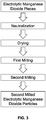
FIG. 2 is a flowchart of a method of producing electrolytic manganese dioxide according to one aspect of the present invention; -
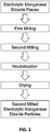
FIG. 3 is a flowchart of a method of producing electrolytic manganese dioxide according to one aspect of the present invention; -
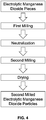
FIG. 4 is a flowchart of a method of producing electrolytic manganese dioxide according to one aspect of the present invention; -
FIG. 5 is a graph showing compact density as a function of milling time when the second milling is conducted after neutralization and drying; -
FIG. 6 is a graph showing compact density as a function of milling time when the second milling is conducted after the first milling step and before neutralization and drying; -
FIG. 7 is a graph showing compact density as a function of milling time when the second milling is conducted between the neutralization step and the drying step; and -
FIG. 8 is a graph showing the particle size distribution for the second milled electrolytic manganese dioxide produced in inventive Example 12. - In a first aspect of the present invention as shown in
FIG. 1 , electrolytic manganese dioxide pieces are milled in a classifying mill. The manganese dioxide pieces may have a having a maximum dimension of less than 100 mm. A classifying mill is a mill that not only crushes and/or grinds the electrolytic manganese dioxide pieces but also classifies the resulting first milled electrolytic manganese dioxide particles to achieve a desired particle size. This first milling can be a wet or dry process and can be conducted using a ball mill, roller mill, Raymond mill, or any other suitable milling equipment having a classifier. During the milling, the electrolytic manganese dioxide pieces are ground into first milled electrolytic manganese dioxide particles, and the classifying portion of the mill is set to allow only first milled electrolytic manganese dioxide particles within a certain size range to exit the mill for use in the next process step. - In another aspect, the first milled electrolytic manganese dioxide particles may have a particle size distribution where less than 15% of the first milled manganese dioxide particles are larger than 200 mesh and up to 70% of the first milled manganese dioxide particles are smaller than 325 mesh.
- The first milled electrolytic manganese dioxide particles are mixed with water to create a slurry. Any suitable base including, but not limited to, sodium hydroxide is added to the slurry to neutralize the electrolytic manganese dioxide particles. The slurry is dewatered and dried to remove most of the water (which may be referred to collectively hereinafter as "a drying step"), leaving about 1 to 3% physisorbed water by weight in the first milled electrolytic manganese dioxide particles. The dewatering may be performed by filtering and the drying may use hot air.
- The first milled electrolytic manganese dioxide particles are then milled a second time. The second milling is conducted in a tumbling mill, for example, a ball mill, ajar mill, or a similar type of tumbling mill. The milling media can be balls, beads, cylinders, or rods made of a non-metallic compound including, but not limited to alumina or zirconia. The size of the milling media may be from about 5mm to about 100 mm. The second milling is conducted for a minimum of 2 minutes, such as 10 minutes, 30 minutes, or 60 minutes or more. In one aspect, the second milling may be conducted for a maximum of 720 minutes. In another aspect, the second milling may be conducted for a maximum of 480 minutes or less.
- In another aspect, as shown in
FIG. 2 , the first milling and the second milling are dry processes, and neutralization and drying are performed on the second milled electrolytic manganese dioxide particles after both the first milling and the second milling have been completed instead of between the two millings. - In another aspect, as shown in
FIG. 3 , the first milling and the second milling are dry processes, and neutralization and drying are performed on the electrolytic manganese dioxide pieces before the first milling instead of between the two millings. - In another aspect, as shown in
FIG. 4 , the first milling is a dry process. The first milled electrolytic manganese dioxide particles are neutralized, and introduced wet into the second milling. Drying is performed on the second milled electrolytic manganese dioxide particles after the second milling. - Without being bound by theory, it is believed that the second milling modifies the particle size distribution in a way that allows, during compaction, for more effective filling of the void space between particles with a particle of the same size as the void space.
- In one aspect of the invention, the compact density of the second milled manganese dioxide particles may be at least 1% greater than a compact density of the first milled manganese dioxide particles. In another aspect of the invention, the compact density of the second milled manganese dioxide particles may be at least 2% greater than a compact density of the first milled manganese dioxide particles. In further aspect of the invention, the compact density of the second milled manganese dioxide particles may be at least 3% greater than a compact density of the first milled manganese dioxide particles.
- In one aspect of the invention, the alkaline potential of neutralized particles of the second milled manganese dioxide particles may be no more than 20 mV less than an alkaline potential of neutralized particles of the first milled manganese dioxide particles. In another aspect of the invention, the alkaline potential of neutralized particles of the second milled manganese dioxide particles may be no more than 10 mV less than an alkaline potential of neutralized particles of the first milled manganese dioxide particles. In a further, aspect of the invention, the alkaline potential of neutralized particles of the second milled manganese dioxide particles may be no more than 5 mV less than an alkaline potential of neutralized particles of the first milled manganese dioxide particles.
- In general, the particle size distribution of electrolytic manganese dioxide particles can be described as an overlap of three Gaussian distributions, when the particle size distribution is plotted as a function of base-10 logarithm of the particle size. A first peak is centered at a particle size below 100 µm, a third peak is centered at a particle size in the range of 0.1-1.0 µm, and a second peak is located between the first peak and the third peak.
- In the particle size distribution of the first milled electrolytic manganese dioxide particles, when plotted as a function of base-10 logarithm of the particle size, the first peak is centered at a particle size greater than 45 µm and contributes a minimum of 45% of the area under the curve of the overall particle size distribution. In another aspect, the first peak may be centered at a particle size greater than 55 µm.
- The following examples are presented to demonstrate the general principles of the invention. The invention should not be considered as limited to the specific examples presented.
- The following examples were tested for particle size distribution, compact density and alkaline potential as described below
- The particle size distribution was measured by laser diffraction using a MicroTrac 3500. The flow rate was set to 60%, the transparency was set to absorbing, particle shape was set to irregular, and a fluid refractive index of 1.333 was used. The milled electrolytic manganese dioxide particles were introduced into the water-containing chamber of the instrument until the software determines that the loading factor was in the correct range. Then the milled electrolytic manganese dioxide particles inside the chamber were exposed to ultrasound at 25 mW for 60 seconds. Diffraction data was taken twice for 60 seconds with a 1 minute delay between the measurements. The average data was presented in a Geom8 Root progression with a lower edge of 0.0215 µm and an upper edge of 704 µm. As a result, 120 data points were collected. The volume percentage, ƒj , of the milled electrolytic manganese dioxide particles having the size, d, of channel j, was determined.
- When plotting the data of ƒj as a function of size (on a logarithmic scale), two apparent peaks were observed, one centered about 55 µm and one centered about 0.4 µm. However, when fitting the observed particle distribution three overlapping Gaussian peaks, gi (x), were used such that the particle size distribution is fit with the following function:


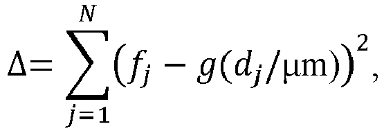
- For the three peaks, Ai is the area under the curve of peak i and the sum, A, of A 1+A 2+A 3 is the total area under the curve of the overall particle size distribution. The relative area under the curve contributed by each peak i is αi = Ai /A.
- An apparatus comprising two cans, a plunger, a pelletizer die, and a canning die was used. Two circular pieces of weighing paper whose diameter was slightly smaller than the can diameter were cut. One circular piece of weighing paper was placed into each of the two cans. One can was labeled with a "0", and the other can was labeled with a "1". The can/paper combination labeled "1" was weighed and the weight was recorded as "Weight Can 1/Paper".
- The can/paper combination labeled "0" was placed into the canning die. The plunger was inserted into the can, and the can/paper were compressed at 4.448.222 kN (1000 lb. force) for 5 seconds using a Carver Press. The pressure was released, five seconds was allowed to pass, and the process was repeated.
- A 700 mg of sample (+/- 50 mg) was placed into the pelletizing die and compressed at 4.448.222 kN (1000 lb. force) for 5 seconds.
- The paper was removed from the can/paper combination labeled "1", and the can was placed in the canning die. The compressed pellet was transferred from the pelletizer die to the canning die so that it fits into the can. The paper was placed on top of the can/pellet and the plunger was inserted.
- The can/pellet/paper was compressed at 4.448.222 kN (1000 lb.) for 1 minute. The pressure was released, five seconds was allowed to pass, and the process was repeated. The can/pellet/paper were removed from the die.
- The can/paper labeled "0" were used to zero a digital micrometer. The pellet height of the can "1"/paper/pellet combination was measured with the digital micrometer and recorded as the "Micrometer Height". The can "1"/paper/pellet combination was weighed on a Microbalance, and the weight was recorded as "Weight Can 1/Paper/Pellet".
- The individual compact density was calculated as

- The alkaline potential of the milled electrolytic manganese dioxide particles was determined by placing 350 ± 50 mg of milled electrolytic manganese dioxide particles into a small nickel-coated can with an inner diameter of about 1.1 cm (0.435 inches) and a height of about 0.48 cm (0.19 inches). 100 µl of 45% KOH solution was pipetted into the can as electrolyte, then two paper disks were placed on top of the particle-electrolyte mixture and the content of the can was tapped down with a stainless steel rod. The same preparation was repeated two more times to create a total of three samples. The three cans were covered to minimize evaporation and set aside for 30-120 minutes to allow for proper wetting of the milled electrolytic manganese dioxide particles. Finally, the cans were placed on a metal mesh. The positive electrode of a voltmeter was connected to the metal mesh and the negative electrode was connected to a Hg/HgO reference electrode (commercially available from Koslow Scientific Company filled with 45% KOH solution). The tip of the reference electrode was placed on top of the paper inside the cans and the voltage measured by the voltmeter was recorded. The values for the three cans were averaged and referred to as a single value of alkaline potential, Φ.
- Electrolytic manganese dioxide pieces with a maximum dimension of less than 100 mm were fed into a 6-roll Raymond mill. The mill was controlled so that 89.2% of the resulting first milled electrolytic manganese dioxide particles smaller than 200 mesh (74µm) and 61.4% of the resulting first milled electrolytic manganese dioxide particles were smaller than 325 mesh (44 µm). The first milled electrolytic manganese dioxide particles were neutralized and dried. The compact density of the neutralized and dried first milled electrolytic manganese dioxide particles was measured and is shown in Table 1.
- The neutralized and dried first milled electrolytic manganese dioxide particles prepared in Comparative Example 1 were fed into a jar mill for the second milling. The internal diameter of the jar was 12,2 cm (4.8 inches) and the internal height of the jar was 9.5 cm (3.75 inches). The volume of the jar was 173 cm3 (68 cubic inches). The milling media was 12 mm Zirconia balls that occupied about 50% of the volume of the jar. The electrolytic manganese dioxide particles filled about 25% of the volume of the jar and weighed 400 grams. The cylindrical jar was placed on the rollers of the mill, and the rotation speed was set at 21 revolutions per minute. Second milled electrolytic manganese dioxide particles were prepared in this manner using second milling times of 240, 210, 180, 150, 120, and 90 minutes. The compact density of the second milled electrolytic manganese dioxide particles was measured and is shown in Table 1 along with the compact density as a percent increase over the compact density of Comparative Example 1. The effect of the second milling time on compact density is shown in
FIG. 5 .Table 1: Compact density as a function of milling time when the second milling was conducted after neutralization and drying. Time of Second Milling (minutes) Compact Density (g/cm3) Change in Compact Density (%) Comparative Example 1 0 2.815 Example 1 240 2.883 2.4 Example 2 210 2.881 2.3 Example 3 180 2.874 2.1 Example 4 150 2.861 1.6 Example 5 120 2.847 1.1 Example 6 90 2.845 1.1 - Electrolytic manganese dioxide pieces with a size of less than 100 mm were fed into a 6-roll Raymond mill. The mill was controlled so that 90% of the resulting first milled electrolytic manganese dioxide particles were smaller than 200 mesh and 60% of the resulting first milled electrolytic manganese dioxide particles were smaller than 325 mesh. The first milled electrolytic manganese dioxide particles were neutralized and dried. The compact density of the neutralized and dried first milled electrolytic manganese dioxide particles was measured and is shown in Table 2.
- First milled electrolytic manganese dioxide particles prepared in Comparative Example 2 prior to neutralization and drying were fed into a jar mill for the second milling. The internal diameter of the jar was 4.8 inches and the internal height of the jar was 3.75 inches. The volume of the jar was 68 cubic inches. The milling media was 12 mm Zirconia balls that occupied about 50% of the volume of the jar. The electrolytic manganese dioxide particles filled about 25% of the volume of the jar and weighed 400 grams. The cylindrical jar was placed on the rollers of the mill, and the rotation speed was set at 21 revolutions per minute. Second milled electrolytic manganese dioxide particles were prepared in this manner using second milling times of 240, 180, 150, 120, and 90 minutes. The second milled electrolytic manganese dioxide particles were then neutralized and dried. The compact density of the second milled electrolytic manganese dioxide particles was measured and is shown in Table 2 along with the compact density as a percent increase over the compact density of Comparative Example 2. The effect of the second milling time on compact density is shown in
FIG. 6 .Table 2: Compact density as a function of milling time when the second milling was conducted after the first milling step and before neutralization and drying. Time of Second Milling (minutes) Compact Density (g/cm3) Change in Compact Density (%) Comparative Example 2 0 2.737 Example 7 240 2.865 4.7 Example 8 180 2.861 4.5 Example 9 150 2.851 4.2 Example 10 120 2.828 3.3 Example 11 90 2.794 2.1 - Electrolytic manganese dioxide pieces with a size of less than 100 mm were fed into a 6-roll Raymond mill. The mill was controlled so that 90% of the resulting first milled electrolytic manganese dioxide particles were smaller than 74 µm (200 mesh) and 60% of the resulting first milled electrolytic manganese dioxide particles were smaller than 44 µm (325 mesh). The first milled electrolytic manganese dioxide particles were neutralized and dried. The compact density of the neutralized and dried first milled electrolytic manganese dioxide particles was measured and is shown in Table 4. In addition, the particle size distribution was determined and the results are given in Tables 3 and 4.
- Neutralized but not dried first milled electrolytic manganese dioxide particles prepared in Comparative Example 3 were filtered to obtain a wet cake of neutralized electrolytic manganese dioxide with 16% moisture. The wet cake was fed into a jar mill for the second milling. The internal diameter of the jar was 4.8 inches and the internal height of the jar was 9.53 cm (3.75 inches). The volume of the jar was 173 cm3 (68 cubic inches). The milling media was 12 mm Zirconia balls that occupied about 50% of the volume of the jar. The wet cake of neutralized electrolytic manganese dioxide particles filled about 25% of the volume of the jar and weighed 475 gram. 40 ml of distilled water was added to the jar. The cylindrical jar was placed on the rollers of the mill, and the rotation speed was set at 21 revolutions per minute. Second milled electrolytic manganese dioxide particles were prepared in this manner using second milling times of 240, 180, and 120 minutes. The second milled electrolytic manganese dioxide particles were then dried. The compact density of the second milled electrolytic manganese dioxide particles was measured and is shown in Table 4 along with the compact density as a percent increase over the compact density of Comparative Example 3. The effect of the second milling time on compact density is shown in
FIG. 7 . In addition, the particle size distribution was determined and the results are given in Tables 3 and 4. The particle size distribution for Example 12 is also shown graphically inFIG. 8 .Table 3: Particle size distribution results for examples where the second milling was conducted between the neutralization step and the drying step. First Peak Second Peak Third Peak i 1 2 3 Comparative Ai 1.87 1.62 0.30 Example 3 xi 59 26 1.0 σ i 0.17 0.42 0.48 αi = Ai /(A 1+A 2+A 3) × 100% 49% 43% 8% Example 12 Ai 1.34 2.04 0.41 xi 42 17 0.5 σ i 0.15 0.48 0.24 αi Ai /(A 1+A 2+A 3) × 100% 35% 54% 11% Example 13 Ai 1.29 2.13 0.37 xi 49 20 0.5 σ i 0.15 0.46 0.25 αi = Ai /(A 1+A 2+A 3) × 100% 34% 56% 10% Example 14 Ai 1.41 2.08 0.30 xi 54 23 0.6 σ i 0.15 0.45 0.29 αi = Ai /(A 1+A 2+A 3) × 100% 37% 55% 8% Table 4: Results for examples where the second milling was conducted between the neutralization and the drying. Time in Second Milling (minutes) Compact Density (g/cm3) Change in Compact Density (%) First Peak (% of area) Third Peak (% of area) Center of First Peak (µm) Center of Second Peak (µm) Comparative Example 3 0 2.754 49% 8% 59 26 Example 12 240 2.863 4.0 35% 11% 42 17 Example 13 180 2.803 1.8 34% 10% 49 20 Example 14 120 2.773 0.7 37% 8% 54 23 - Similar to Comparative Example 1, electrolytic manganese dioxide was prepared by a first milling step, a neutralization step, and a drying step. The particle size distribution of the first milled electrolytic manganese dioxide particles was then analyzed. Results are shown in Table 5. In addition, the alkaline potential Φ0 of the first milled electrolytic manganese dioxide particles was determined and the results are shown in Table 5.
- The first milled electrolytic manganese dioxide particles of Comparative Example 4 were subjected to a second milling, similar to the one described in Example 1. The second milling was conducted for about 2 minutes. About 5-10 g of second milled electrolytic manganese dioxide particles were removed from the jar to determine the particle size distribution and the alkaline potential Φ2. Table 2 shows the difference in alkaline potential between this Comparative Example 4 and Comparative Example 4, i.e. ΔΦ= Φ2 - Φ0. After 2 minutes of secondary milling, the particle size distribution and the alkaline potential of the second milled electrolytic manganese dioxide particles are not substantially different from the first milled electrolytic manganese dioxide particles.
- The second milling of Comparative Example 5 was continued for another 58 minutes for a total of about 60 minutes. About 5-10 g of electrolytic manganese dioxide was removed from the jar to determine the particle size distribution. The alkaline potential was also determined and compared to the alkaline potential of Comparative Example 4. The results are shown in Table 5. While the particle size distribution changed, no change in the alkaline potential was observed.
- The second milling of Comparative Example 5 was continued for another 30 minutes for a total of about 90 minutes. About 5-10 g of electrolytic manganese dioxide was removed from the jar to determine the particle size distribution. The alkaline potential was also determined and compared to the alkaline potential of Comparative Example 4. The results are shown in Table 5. Again, while the particle size distribution changed, no change in the alkaline potential was observed.
- The second milling of Comparative Example 5 was continued for another 30 minutes for a total of about 120 minutes. About 5-10 g of electrolytic manganese dioxide was removed from the jar to determine the particle size distribution. The alkaline potential was also determined and compared to the alkaline potential of Comparative Example 4. The results are shown in Table 5. Again, while the particle size distribution changed, no change in the alkaline potential was observed.
- The second milling of Comparative Example 5 was continued for another 120 minutes for a total of about 240 minutes. About 5-10 g of electrolytic manganese dioxide was removed from the jar to determine the particle size distribution. The alkaline potential was also determined and compared to the alkaline potential of Comparative Example 4. The results are shown in Table 5. While the particle size distribution changed, only a small change in the alkaline potential was observed.
- The second milling of Comparative Example 5 was continued for another 240 minutes for a total of about 480 minutes. About 5-10 g of electrolytic manganese dioxide was removed from the jar to determine the particle size distribution. The alkaline potential was also determined and compared to the alkaline potential of Comparative Example 4. Again, while the particle size distribution changed, only a small change in the alkaline potential was observed.
- The first milled electrolytic manganese dioxide particles of Comparative Example 4 were subjected to a second milling, similar to the one described in Example 1. The second milling was conducted for about 720 minutes. Then, the particle size distribution was measured. The alkaline potential was also determined and compared to the alkaline potential of Comparative Example 4. The results are shown in Table 5. With the additional milling, the amount of material with a size of less than 1 µm was increased as indicated by the percentage of area under the curve of the overall particle size distribution contributed by the third peak which is centered around a particle size of 0.1-1 µm.
- The second milling step of Example 19 was continued for another 960 minutes for a total of 1440 minutes. Then, the particle size distribution was measured. The alkaline potential was also determined and compared to the alkaline potential of Comparative Example 4. The results are shown in Table 5. With the additional milling, the amount of material with a size of less than 1 µm was increased as indicated by the percentage of area under the curve of the overall particle size distribution contributed by the third peak which is centered around a particle size of 0.1-1 µm.
Table 5: Particle size evolution and alkaline potential where the second milling was conducted after neutralization and drying Time in Second Milling (minutes) First Peak (% of area) Third Peak (% of area) Center of First Peak (µm) Center of Second Peak (µm) ΔΦ (Φsample - Φ0) (mV) Comparative Example 4 0 52% 8% 64 29 Comparative Example 5 2 52% 8% 63 29 0 Example 15 60 42% 13% 58 27 0 Example 16 90 42% 13% 55 26 0 Example 17 120 41% 14% 53 24 0 Example 18 240 37% 19% 47 20 -3 Example 19 480 30% 27% 39 14 -4 Example 20 720 27% 29% 36 10 -10 Example21 1440 26% 32% 28 8 -17
Claims (13)
- A method for producing electrolytic manganese dioxide with high compact density comprising:producing first milled manganese dioxide particles in a classifying mill from electrolytic manganese dioxide pieces by a process comprising dry or wet milling in a ball mill, roller mill or Raymond mill and classification, such that the first milled manganese dioxide particles have a particle size distribution where less than 30% of the first milled manganese dioxide particles are larger than 74 µm (200 mesh) and up to 95% of the first milled manganese dioxide particles are smaller than 44 µm (325 mesh); andmilling the first milled manganese dioxide particles in a tumbling mill with milling media of a size of 5 mm to 100 mm for a time of more than 2 minutes to less than 720 minutes to produce second milled manganese dioxide particles, wherein the second milled manganese dioxide particles have a second particle size distribution,wherein when the particle size distribution of the second milled manganese dioxide particles is plotted as a function of base-10 logarithm of the particle size, the particle size distribution comprises a first peak centered at a particle size of 40-100 µm and contributing 20-45 % to the area under the curve of the overall particle size distribution, a second peak centered at a particle size of 15-25 µm, and a third peak centered at a particle size of 0.1-1.0 µm and having a contribution of 20% maximum to the area under the curve of the overall particle size distribution,the particle size distribution was measured by laser diffraction using a Micro Trac 3500 apparatus, the flow rate was set to 60%, the transparency was set to absorbing, particle shape was set to irregular, and a fluid index of 1.333 was used.
- The method of claim 1, wherein 50-95% of the first milled manganese dioxide particles are smaller than 325 mesh.
- The method of claim 1, wherein less than 15% of the first milled manganese dioxide particles are larger than 200 mesh and up to 70% of the first milled manganese dioxide particles are smaller than 325 mesh.
- The method of claim 3, wherein 85-95% of the first milled manganese dioxide particles are smaller than 200 mesh and 50-70% of the first milled manganese dioxide particles are smaller than 325 mesh.
- The method of claim 1, wherein when particle size distribution of the first milled manganese dioxide particles is plotted as a function of base-10 logarithm of the particle size, the particle size distribution comprises a peak centered at a particle size greater than 45 µm that contributes at least 45% to the area under the curve of the overall particle size distribution.
- The method of claim 5, wherein the first peak is centered at a particle size greater than 55 µm and contributes at least 45% to the area under the curve of the overall particle size distribution.
- The method of claim 1, wherein a compact density of the second milled manganese dioxide particles is at least 1% greater than a compact density of the first milled manganese dioxide particles.
- The method of claim 1, wherein an alkaline potential of neutralized particles of the second milled manganese dioxide particles is no more than 20 mV less than an alkaline potential of neutralized particles of the first milled manganese dioxide particles.
- The method of claim 1, further comprising neutralizing and/or drying the first milled manganese dioxide particles before the second milling.
- The method of claim 1, further comprising neutralizing and/or drying the second milled manganese dioxide particles.
- The method of claim 1, further comprising neutralizing the first milled manganese dioxide particles before the second milling and performing the second milling on neutralized, wet first-milled manganese dioxide particles.
- The method of claim 11, further comprising drying the second milled manganese dioxide particles.
- An electrolytic manganese dioxide particle composition having a particle size distribution, wherein when the particle size distribution is measured by laser diffraction using a Micro Trac 3500 apparatus with the flow rate set to 60%; the transparency set to absorbing; particle shape set to irregular; and with a fluid index of 1.333 and then plotted as a function of base-10 logarithm of the particle size, the particle size distribution comprises a first peak centered at a particle size of 40-100 µm that contributes 20%-40% to the area under the curve of the overall particle size distribution, a second peak centered at a particle size of 15-25 µm, and a third peak centered at a particle size of 0.1-1.0 µm that has a contribution of 20% maximum to the area under the curve of the overall particle size distribution.
Applications Claiming Priority (2)
| Application Number | Priority Date | Filing Date | Title |
|---|---|---|---|
| US201461981942P | 2014-04-21 | 2014-04-21 | |
| PCT/US2015/026641 WO2015164248A1 (en) | 2014-04-21 | 2015-04-20 | Method of producing electrolytic manganese dioxide with high compact density and electrolytic manganese dioxide produced therefrom |
Publications (3)
| Publication Number | Publication Date |
|---|---|
| EP3134933A1 EP3134933A1 (en) | 2017-03-01 |
| EP3134933A4 EP3134933A4 (en) | 2018-03-14 |
| EP3134933B1 true EP3134933B1 (en) | 2020-10-21 |
Family
ID=54321396
Family Applications (1)
| Application Number | Title | Priority Date | Filing Date |
|---|---|---|---|
| EP15783473.0A Revoked EP3134933B1 (en) | 2014-04-21 | 2015-04-20 | Method of producing electrolytic manganese dioxide with high compact density and electrolytic manganese dioxide produced therefrom |
Country Status (5)
| Country | Link |
|---|---|
| US (1) | US10099940B2 (en) |
| EP (1) | EP3134933B1 (en) |
| JP (1) | JP6749247B2 (en) |
| CN (1) | CN106604893B (en) |
| WO (1) | WO2015164248A1 (en) |
Families Citing this family (7)
| Publication number | Priority date | Publication date | Assignee | Title |
|---|---|---|---|---|
| JP6822067B2 (en) * | 2016-10-31 | 2021-01-27 | 東ソー株式会社 | Electrolyzed manganese dioxide and its uses |
| JP7039927B2 (en) * | 2016-10-31 | 2022-03-23 | 東ソー株式会社 | Electrolyzed manganese dioxide and its uses |
| CN107185426B (en) * | 2017-07-09 | 2023-06-20 | 贵州大学 | Raw material mixing device for beer production |
| CN108793256B (en) * | 2018-06-26 | 2022-10-11 | 普瑞斯矿业(中国)有限公司 | Electrolytic manganese dioxide powder and preparation method thereof |
| JP7243081B2 (en) * | 2018-08-29 | 2023-03-22 | 東ソー株式会社 | Electrolytic manganese dioxide, method for producing the same, and use thereof |
| CN110257851B (en) * | 2019-06-11 | 2020-08-21 | 湖南顺隆能源有限公司 | Special electrolytic manganese dioxide for lithium manganate battery and preparation method thereof |
| CN113171851B (en) * | 2021-04-20 | 2022-07-05 | 广西下田锰矿有限责任公司 | Preparation method and preparation device of electrolytic manganese dioxide |
Citations (11)
| Publication number | Priority date | Publication date | Assignee | Title |
|---|---|---|---|---|
| US4405419A (en) | 1979-12-13 | 1983-09-20 | Japan Metal And Chemical Co., Ltd. | Method for producing electrolytic manganese dioxide |
| US20020046955A1 (en) | 2000-09-01 | 2002-04-25 | Tosoh Corporation | Powder of electrolytic manganese dioxide and process for producing the same |
| US20020136955A1 (en) | 1999-12-15 | 2002-09-26 | Hong-Kyu Park | Method for preparing lithium manganese spinel oxide having improved electrochemical performance |
| JP2002348693A (en) | 2000-09-01 | 2002-12-04 | Tosoh Corp | Electrolytic manganese dioxide powder and method for producing the same |
| US20050227145A1 (en) * | 2004-04-09 | 2005-10-13 | Hitachi Maxwell, Ltd. | Alkaline battery |
| KR100610596B1 (en) | 1998-12-21 | 2006-08-09 | 트로녹스 엘엘씨 | Electrolytic Manganese Dioxide with Large Discharge Capacity and Manufacturing Method thereof |
| CN101774645A (en) | 2010-01-13 | 2010-07-14 | 彭天剑 | Sphere-like manganese dioxide and preparation method thereof |
| JP2010251221A (en) | 2009-04-20 | 2010-11-04 | Tosoh Corp | Electrolytic manganese dioxide composition having excellent high rate characteristics |
| WO2011085438A1 (en) | 2010-01-13 | 2011-07-21 | Galaxy Resources Limited | Process for the production of electrolytic manganese dioxide |
| JP2011251862A (en) | 2010-06-01 | 2011-12-15 | Tosoh Corp | Manganese oxide and method for producing the same |
| US20130330268A1 (en) | 2011-02-18 | 2013-12-12 | Tosoh Corporation | Electrolytic manganese dioxide and method for producing same, and method for producing lithium-manganese complex oxide |
Family Cites Families (11)
| Publication number | Priority date | Publication date | Assignee | Title |
|---|---|---|---|---|
| CA385405A (en) * | 1939-12-05 | Wallace Gibson William | Crushing, grinding and classifying mill | |
| US3888790A (en) * | 1971-11-24 | 1975-06-10 | Du Pont | Process for preparing a catalytically active ceramic coatings |
| US4697744A (en) * | 1984-10-16 | 1987-10-06 | Sumitomo Metal Industries, Ltd. | Process for the production of iron oxide fine powder |
| US4549943A (en) * | 1984-11-01 | 1985-10-29 | Union Carbide Corporation | Suspension bath and process for production of electrolytic manganese dioxide |
| US4989794A (en) * | 1986-07-16 | 1991-02-05 | Alcan International Limited | Method of producing fine particles |
| US6403257B1 (en) * | 2000-07-10 | 2002-06-11 | The Gillette Company | Mechanochemical synthesis of lithiated manganese dioxide |
| JP2002248693A (en) * | 2001-02-26 | 2002-09-03 | Toray Ind Inc | Frp long molded object and method for manufacturing the same |
| JP4773355B2 (en) * | 2003-05-19 | 2011-09-14 | キャボット コーポレイション | Niobium oxide and method for producing niobium oxide with reduced oxygen |
| BRPI0804694B1 (en) * | 2008-07-25 | 2018-11-21 | Vale Do Rio Doce Co | Manganese pellet production process from non-calcined manganese ore and manganese pellet obtained by such process |
| US8303840B2 (en) | 2010-03-12 | 2012-11-06 | The Gillette Company | Acid-treated manganese dioxide and methods of making thereof |
| CN102347479A (en) * | 2010-08-06 | 2012-02-08 | 无锡晶石新型能源有限公司 | Method and device for processing electrolytic manganese dioxide for lithium ion batteries |
-
2015
- 2015-04-20 WO PCT/US2015/026641 patent/WO2015164248A1/en not_active Ceased
- 2015-04-20 EP EP15783473.0A patent/EP3134933B1/en not_active Revoked
- 2015-04-20 JP JP2016564084A patent/JP6749247B2/en active Active
- 2015-04-20 CN CN201580029497.2A patent/CN106604893B/en active Active
- 2015-04-20 US US14/690,709 patent/US10099940B2/en active Active
Patent Citations (11)
| Publication number | Priority date | Publication date | Assignee | Title |
|---|---|---|---|---|
| US4405419A (en) | 1979-12-13 | 1983-09-20 | Japan Metal And Chemical Co., Ltd. | Method for producing electrolytic manganese dioxide |
| KR100610596B1 (en) | 1998-12-21 | 2006-08-09 | 트로녹스 엘엘씨 | Electrolytic Manganese Dioxide with Large Discharge Capacity and Manufacturing Method thereof |
| US20020136955A1 (en) | 1999-12-15 | 2002-09-26 | Hong-Kyu Park | Method for preparing lithium manganese spinel oxide having improved electrochemical performance |
| US20020046955A1 (en) | 2000-09-01 | 2002-04-25 | Tosoh Corporation | Powder of electrolytic manganese dioxide and process for producing the same |
| JP2002348693A (en) | 2000-09-01 | 2002-12-04 | Tosoh Corp | Electrolytic manganese dioxide powder and method for producing the same |
| US20050227145A1 (en) * | 2004-04-09 | 2005-10-13 | Hitachi Maxwell, Ltd. | Alkaline battery |
| JP2010251221A (en) | 2009-04-20 | 2010-11-04 | Tosoh Corp | Electrolytic manganese dioxide composition having excellent high rate characteristics |
| CN101774645A (en) | 2010-01-13 | 2010-07-14 | 彭天剑 | Sphere-like manganese dioxide and preparation method thereof |
| WO2011085438A1 (en) | 2010-01-13 | 2011-07-21 | Galaxy Resources Limited | Process for the production of electrolytic manganese dioxide |
| JP2011251862A (en) | 2010-06-01 | 2011-12-15 | Tosoh Corp | Manganese oxide and method for producing the same |
| US20130330268A1 (en) | 2011-02-18 | 2013-12-12 | Tosoh Corporation | Electrolytic manganese dioxide and method for producing same, and method for producing lithium-manganese complex oxide |
Non-Patent Citations (1)
| Title |
|---|
| ANONYMOUS: "BROCHURE MICROTRAC MRB Particle Characterization", 1 April 2020 (2020-04-01), pages 1 - 9, XP055828438 |
Also Published As
| Publication number | Publication date |
|---|---|
| US20150298989A1 (en) | 2015-10-22 |
| EP3134933A4 (en) | 2018-03-14 |
| JP6749247B2 (en) | 2020-09-02 |
| CN106604893B (en) | 2019-01-18 |
| CN106604893A (en) | 2017-04-26 |
| US10099940B2 (en) | 2018-10-16 |
| WO2015164248A1 (en) | 2015-10-29 |
| EP3134933A1 (en) | 2017-03-01 |
| JP2017522251A (en) | 2017-08-10 |
Similar Documents
| Publication | Publication Date | Title |
|---|---|---|
| EP3134933B1 (en) | Method of producing electrolytic manganese dioxide with high compact density and electrolytic manganese dioxide produced therefrom | |
| DE69907660T2 (en) | ACTIVE MATERIAL OF A POSITIVE ELECTRODE FOR NON-AQUEOUS ELECTRODE SECONDARY BATTERY AND METHOD FOR THE PRODUCTION THEREOF AND NON-AQUEOUS SECONDARY BATTERY USING THIS | |
| CZ342498A3 (en) | Process for producing powder of metallic tantalum with controlled distribution of particle size and products obtained in such a manner | |
| EP3027690A1 (en) | Method for size-reduction of silicon and use of the size-reduced silicon in a lithium-ion battery | |
| CN118610395B (en) | Positive electrode material and battery | |
| EP3032556B1 (en) | Method for producing electrode film for electric double layer capacitors | |
| EP1184919B1 (en) | Powder of electrolytic manganese dioxide and process for producing the same | |
| EP2645458B1 (en) | Alkaline storage battery | |
| JP6394645B2 (en) | Manufacturing method of negative electrode plate | |
| JP3341693B2 (en) | Active material powder for electrode of silver oxide battery, electrode material and production method thereof | |
| EP2768048B1 (en) | Alkaline cell | |
| JP6862766B2 (en) | Electrolyzed manganese dioxide, its manufacturing method and its uses | |
| EP3816110B1 (en) | Preparation method for electrolytic manganese dioxide powder | |
| EP2811556A1 (en) | Manganese dioxide, and alkaline dry cell using same | |
| EP3889322A1 (en) | Electrolytic manganese dioxide, method for manufacturing same, and use thereof | |
| CN101184568B (en) | Metal powder and manufacturing methods thereof | |
| DE4010811C1 (en) | ||
| JP5439924B2 (en) | Electrolytic manganese dioxide composition having excellent high rate characteristics | |
| JP7039927B2 (en) | Electrolyzed manganese dioxide and its uses | |
| EP4421895A1 (en) | Battery and electrical apparatus | |
| EP4406917A2 (en) | Acid treatment of linio2 to decrease gamma-niooh formation | |
| EP4403518A1 (en) | Silicon-based molded body and method for continuously preparing silicon oxide by using same | |
| JP2016186889A (en) | Recycle method for negative electrode for nickel hydrogen secondary battery | |
| EP2722913B1 (en) | Anode mixture, button cell with an anode comprising a metal particle and their preparation | |
| CN120513219A (en) | Method for reducing gamma-NiOOH in battery material |
Legal Events
| Date | Code | Title | Description |
|---|---|---|---|
| STAA | Information on the status of an ep patent application or granted ep patent |
Free format text: STATUS: THE INTERNATIONAL PUBLICATION HAS BEEN MADE |
|
| PUAI | Public reference made under article 153(3) epc to a published international application that has entered the european phase |
Free format text: ORIGINAL CODE: 0009012 |
|
| STAA | Information on the status of an ep patent application or granted ep patent |
Free format text: STATUS: REQUEST FOR EXAMINATION WAS MADE |
|
| 17P | Request for examination filed |
Effective date: 20161108 |
|
| AK | Designated contracting states |
Kind code of ref document: A1 Designated state(s): AL AT BE BG CH CY CZ DE DK EE ES FI FR GB GR HR HU IE IS IT LI LT LU LV MC MK MT NL NO PL PT RO RS SE SI SK SM TR |
|
| AX | Request for extension of the european patent |
Extension state: BA ME |
|
| RIN1 | Information on inventor provided before grant (corrected) |
Inventor name: KEEL, KEITH, A. Inventor name: SCHILLING, OLIVER Inventor name: BEI, XU |
|
| DAV | Request for validation of the european patent (deleted) | ||
| DAX | Request for extension of the european patent (deleted) | ||
| RAP1 | Party data changed (applicant data changed or rights of an application transferred) |
Owner name: PRINCE ERACHEM, INC. |
|
| REG | Reference to a national code |
Ref country code: DE Ref legal event code: R079 Ref document number: 602015060849 Country of ref document: DE Free format text: PREVIOUS MAIN CLASS: H01M0008040000 Ipc: C01G0045020000 |
|
| RIC1 | Information provided on ipc code assigned before grant |
Ipc: C01G 45/02 20060101AFI20180131BHEP Ipc: B02C 13/13 20060101ALI20180131BHEP Ipc: H01M 8/04 20160101ALI20180131BHEP Ipc: C25B 1/21 20060101ALI20180131BHEP |
|
| A4 | Supplementary search report drawn up and despatched |
Effective date: 20180209 |
|
| STAA | Information on the status of an ep patent application or granted ep patent |
Free format text: STATUS: EXAMINATION IS IN PROGRESS |
|
| 17Q | First examination report despatched |
Effective date: 20181220 |
|
| TPAC | Observations filed by third parties |
Free format text: ORIGINAL CODE: EPIDOSNTIPA |
|
| TPAC | Observations filed by third parties |
Free format text: ORIGINAL CODE: EPIDOSNTIPA |
|
| TPAC | Observations filed by third parties |
Free format text: ORIGINAL CODE: EPIDOSNTIPA |
|
| RAP1 | Party data changed (applicant data changed or rights of an application transferred) |
Owner name: PRINCE SPECIALTY PRODUCTS LLC |
|
| TPAC | Observations filed by third parties |
Free format text: ORIGINAL CODE: EPIDOSNTIPA |
|
| GRAP | Despatch of communication of intention to grant a patent |
Free format text: ORIGINAL CODE: EPIDOSNIGR1 |
|
| STAA | Information on the status of an ep patent application or granted ep patent |
Free format text: STATUS: GRANT OF PATENT IS INTENDED |
|
| INTG | Intention to grant announced |
Effective date: 20200603 |
|
| GRAS | Grant fee paid |
Free format text: ORIGINAL CODE: EPIDOSNIGR3 |
|
| GRAA | (expected) grant |
Free format text: ORIGINAL CODE: 0009210 |
|
| STAA | Information on the status of an ep patent application or granted ep patent |
Free format text: STATUS: THE PATENT HAS BEEN GRANTED |
|
| AK | Designated contracting states |
Kind code of ref document: B1 Designated state(s): AL AT BE BG CH CY CZ DE DK EE ES FI FR GB GR HR HU IE IS IT LI LT LU LV MC MK MT NL NO PL PT RO RS SE SI SK SM TR |
|
| REG | Reference to a national code |
Ref country code: GB Ref legal event code: FG4D |
|
| REG | Reference to a national code |
Ref country code: CH Ref legal event code: EP |
|
| REG | Reference to a national code |
Ref country code: IE Ref legal event code: FG4D |
|
| REG | Reference to a national code |
Ref country code: DE Ref legal event code: R096 Ref document number: 602015060849 Country of ref document: DE |
|
| REG | Reference to a national code |
Ref country code: AT Ref legal event code: REF Ref document number: 1325676 Country of ref document: AT Kind code of ref document: T Effective date: 20201115 |
|
| REG | Reference to a national code |
Ref country code: GR Ref legal event code: EP Ref document number: 20200403087 Country of ref document: GR Effective date: 20201215 |
|
| REG | Reference to a national code |
Ref country code: AT Ref legal event code: MK05 Ref document number: 1325676 Country of ref document: AT Kind code of ref document: T Effective date: 20201021 |
|
| REG | Reference to a national code |
Ref country code: NL Ref legal event code: MP Effective date: 20201021 |
|
| PG25 | Lapsed in a contracting state [announced via postgrant information from national office to epo] |
Ref country code: FI Free format text: LAPSE BECAUSE OF FAILURE TO SUBMIT A TRANSLATION OF THE DESCRIPTION OR TO PAY THE FEE WITHIN THE PRESCRIBED TIME-LIMIT Effective date: 20201021 Ref country code: RS Free format text: LAPSE BECAUSE OF FAILURE TO SUBMIT A TRANSLATION OF THE DESCRIPTION OR TO PAY THE FEE WITHIN THE PRESCRIBED TIME-LIMIT Effective date: 20201021 Ref country code: PT Free format text: LAPSE BECAUSE OF FAILURE TO SUBMIT A TRANSLATION OF THE DESCRIPTION OR TO PAY THE FEE WITHIN THE PRESCRIBED TIME-LIMIT Effective date: 20210222 Ref country code: NO Free format text: LAPSE BECAUSE OF FAILURE TO SUBMIT A TRANSLATION OF THE DESCRIPTION OR TO PAY THE FEE WITHIN THE PRESCRIBED TIME-LIMIT Effective date: 20210121 Ref country code: NL Free format text: LAPSE BECAUSE OF FAILURE TO SUBMIT A TRANSLATION OF THE DESCRIPTION OR TO PAY THE FEE WITHIN THE PRESCRIBED TIME-LIMIT Effective date: 20201021 |
|
| REG | Reference to a national code |
Ref country code: LT Ref legal event code: MG4D |
|
| PG25 | Lapsed in a contracting state [announced via postgrant information from national office to epo] |
Ref country code: IS Free format text: LAPSE BECAUSE OF FAILURE TO SUBMIT A TRANSLATION OF THE DESCRIPTION OR TO PAY THE FEE WITHIN THE PRESCRIBED TIME-LIMIT Effective date: 20210221 Ref country code: SE Free format text: LAPSE BECAUSE OF FAILURE TO SUBMIT A TRANSLATION OF THE DESCRIPTION OR TO PAY THE FEE WITHIN THE PRESCRIBED TIME-LIMIT Effective date: 20201021 Ref country code: LV Free format text: LAPSE BECAUSE OF FAILURE TO SUBMIT A TRANSLATION OF THE DESCRIPTION OR TO PAY THE FEE WITHIN THE PRESCRIBED TIME-LIMIT Effective date: 20201021 Ref country code: BG Free format text: LAPSE BECAUSE OF FAILURE TO SUBMIT A TRANSLATION OF THE DESCRIPTION OR TO PAY THE FEE WITHIN THE PRESCRIBED TIME-LIMIT Effective date: 20210121 Ref country code: AT Free format text: LAPSE BECAUSE OF FAILURE TO SUBMIT A TRANSLATION OF THE DESCRIPTION OR TO PAY THE FEE WITHIN THE PRESCRIBED TIME-LIMIT Effective date: 20201021 Ref country code: ES Free format text: LAPSE BECAUSE OF FAILURE TO SUBMIT A TRANSLATION OF THE DESCRIPTION OR TO PAY THE FEE WITHIN THE PRESCRIBED TIME-LIMIT Effective date: 20201021 |
|
| PG25 | Lapsed in a contracting state [announced via postgrant information from national office to epo] |
Ref country code: HR Free format text: LAPSE BECAUSE OF FAILURE TO SUBMIT A TRANSLATION OF THE DESCRIPTION OR TO PAY THE FEE WITHIN THE PRESCRIBED TIME-LIMIT Effective date: 20201021 |
|
| REG | Reference to a national code |
Ref country code: DE Ref legal event code: R026 Ref document number: 602015060849 Country of ref document: DE |
|
| PLBI | Opposition filed |
Free format text: ORIGINAL CODE: 0009260 |
|
| PG25 | Lapsed in a contracting state [announced via postgrant information from national office to epo] |
Ref country code: SM Free format text: LAPSE BECAUSE OF FAILURE TO SUBMIT A TRANSLATION OF THE DESCRIPTION OR TO PAY THE FEE WITHIN THE PRESCRIBED TIME-LIMIT Effective date: 20201021 Ref country code: EE Free format text: LAPSE BECAUSE OF FAILURE TO SUBMIT A TRANSLATION OF THE DESCRIPTION OR TO PAY THE FEE WITHIN THE PRESCRIBED TIME-LIMIT Effective date: 20201021 Ref country code: CZ Free format text: LAPSE BECAUSE OF FAILURE TO SUBMIT A TRANSLATION OF THE DESCRIPTION OR TO PAY THE FEE WITHIN THE PRESCRIBED TIME-LIMIT Effective date: 20201021 Ref country code: LT Free format text: LAPSE BECAUSE OF FAILURE TO SUBMIT A TRANSLATION OF THE DESCRIPTION OR TO PAY THE FEE WITHIN THE PRESCRIBED TIME-LIMIT Effective date: 20201021 Ref country code: SK Free format text: LAPSE BECAUSE OF FAILURE TO SUBMIT A TRANSLATION OF THE DESCRIPTION OR TO PAY THE FEE WITHIN THE PRESCRIBED TIME-LIMIT Effective date: 20201021 Ref country code: RO Free format text: LAPSE BECAUSE OF FAILURE TO SUBMIT A TRANSLATION OF THE DESCRIPTION OR TO PAY THE FEE WITHIN THE PRESCRIBED TIME-LIMIT Effective date: 20201021 |
|
| PLAX | Notice of opposition and request to file observation + time limit sent |
Free format text: ORIGINAL CODE: EPIDOSNOBS2 |
|
| 26 | Opposition filed |
Opponent name: MARKUS REINHARDT Effective date: 20210719 |
|
| PG25 | Lapsed in a contracting state [announced via postgrant information from national office to epo] |
Ref country code: DK Free format text: LAPSE BECAUSE OF FAILURE TO SUBMIT A TRANSLATION OF THE DESCRIPTION OR TO PAY THE FEE WITHIN THE PRESCRIBED TIME-LIMIT Effective date: 20201021 |
|
| PG25 | Lapsed in a contracting state [announced via postgrant information from national office to epo] |
Ref country code: IT Free format text: LAPSE BECAUSE OF FAILURE TO SUBMIT A TRANSLATION OF THE DESCRIPTION OR TO PAY THE FEE WITHIN THE PRESCRIBED TIME-LIMIT Effective date: 20201021 Ref country code: AL Free format text: LAPSE BECAUSE OF FAILURE TO SUBMIT A TRANSLATION OF THE DESCRIPTION OR TO PAY THE FEE WITHIN THE PRESCRIBED TIME-LIMIT Effective date: 20201021 |
|
| PG25 | Lapsed in a contracting state [announced via postgrant information from national office to epo] |
Ref country code: SI Free format text: LAPSE BECAUSE OF FAILURE TO SUBMIT A TRANSLATION OF THE DESCRIPTION OR TO PAY THE FEE WITHIN THE PRESCRIBED TIME-LIMIT Effective date: 20201021 Ref country code: MC Free format text: LAPSE BECAUSE OF FAILURE TO SUBMIT A TRANSLATION OF THE DESCRIPTION OR TO PAY THE FEE WITHIN THE PRESCRIBED TIME-LIMIT Effective date: 20201021 |
|
| PLBB | Reply of patent proprietor to notice(s) of opposition received |
Free format text: ORIGINAL CODE: EPIDOSNOBS3 |
|
| GBPC | Gb: european patent ceased through non-payment of renewal fee |
Effective date: 20210420 |
|
| PG25 | Lapsed in a contracting state [announced via postgrant information from national office to epo] |
Ref country code: LU Free format text: LAPSE BECAUSE OF NON-PAYMENT OF DUE FEES Effective date: 20210420 |
|
| PG25 | Lapsed in a contracting state [announced via postgrant information from national office to epo] |
Ref country code: CH Free format text: LAPSE BECAUSE OF NON-PAYMENT OF DUE FEES Effective date: 20210430 Ref country code: LI Free format text: LAPSE BECAUSE OF NON-PAYMENT OF DUE FEES Effective date: 20210430 Ref country code: FR Free format text: LAPSE BECAUSE OF NON-PAYMENT OF DUE FEES Effective date: 20210430 Ref country code: GB Free format text: LAPSE BECAUSE OF NON-PAYMENT OF DUE FEES Effective date: 20210420 |
|
| PG25 | Lapsed in a contracting state [announced via postgrant information from national office to epo] |
Ref country code: IE Free format text: LAPSE BECAUSE OF NON-PAYMENT OF DUE FEES Effective date: 20210420 |
|
| PG25 | Lapsed in a contracting state [announced via postgrant information from national office to epo] |
Ref country code: IS Free format text: LAPSE BECAUSE OF FAILURE TO SUBMIT A TRANSLATION OF THE DESCRIPTION OR TO PAY THE FEE WITHIN THE PRESCRIBED TIME-LIMIT Effective date: 20210221 |
|
| PG25 | Lapsed in a contracting state [announced via postgrant information from national office to epo] |
Ref country code: HU Free format text: LAPSE BECAUSE OF FAILURE TO SUBMIT A TRANSLATION OF THE DESCRIPTION OR TO PAY THE FEE WITHIN THE PRESCRIBED TIME-LIMIT; INVALID AB INITIO Effective date: 20150420 |
|
| PG25 | Lapsed in a contracting state [announced via postgrant information from national office to epo] |
Ref country code: CY Free format text: LAPSE BECAUSE OF FAILURE TO SUBMIT A TRANSLATION OF THE DESCRIPTION OR TO PAY THE FEE WITHIN THE PRESCRIBED TIME-LIMIT Effective date: 20201021 |
|
| PGFP | Annual fee paid to national office [announced via postgrant information from national office to epo] |
Ref country code: DE Payment date: 20230331 Year of fee payment: 9 |
|
| PG25 | Lapsed in a contracting state [announced via postgrant information from national office to epo] |
Ref country code: MK Free format text: LAPSE BECAUSE OF FAILURE TO SUBMIT A TRANSLATION OF THE DESCRIPTION OR TO PAY THE FEE WITHIN THE PRESCRIBED TIME-LIMIT Effective date: 20201021 |
|
| PGFP | Annual fee paid to national office [announced via postgrant information from national office to epo] |
Ref country code: GR Payment date: 20240429 Year of fee payment: 10 |
|
| PGFP | Annual fee paid to national office [announced via postgrant information from national office to epo] |
Ref country code: PL Payment date: 20240404 Year of fee payment: 10 |
|
| PGFP | Annual fee paid to national office [announced via postgrant information from national office to epo] |
Ref country code: BE Payment date: 20240429 Year of fee payment: 10 |
|
| PG25 | Lapsed in a contracting state [announced via postgrant information from national office to epo] |
Ref country code: MT Free format text: LAPSE BECAUSE OF FAILURE TO SUBMIT A TRANSLATION OF THE DESCRIPTION OR TO PAY THE FEE WITHIN THE PRESCRIBED TIME-LIMIT Effective date: 20201021 |
|
| RDAF | Communication despatched that patent is revoked |
Free format text: ORIGINAL CODE: EPIDOSNREV1 |
|
| REG | Reference to a national code |
Ref country code: DE Ref legal event code: R103 Ref document number: 602015060849 Country of ref document: DE Ref country code: DE Ref legal event code: R064 Ref document number: 602015060849 Country of ref document: DE |
|
| RDAG | Patent revoked |
Free format text: ORIGINAL CODE: 0009271 |
|
| STAA | Information on the status of an ep patent application or granted ep patent |
Free format text: STATUS: PATENT REVOKED |
|
| REG | Reference to a national code |
Ref country code: CH Ref legal event code: PL |
|
| 27W | Patent revoked |
Effective date: 20241206 |
|
| REG | Reference to a national code |
Ref country code: GR Ref legal event code: NF Ref document number: 20200403087 Country of ref document: GR Effective date: 20250514 |
|
| PG25 | Lapsed in a contracting state [announced via postgrant information from national office to epo] |
Ref country code: GR Free format text: THE PATENT HAS BEEN ANNULLED BY A DECISION OF A NATIONAL AUTHORITY Effective date: 20250407 |
|
| PG25 | Lapsed in a contracting state [announced via postgrant information from national office to epo] |
Ref country code: TR Free format text: LAPSE BECAUSE OF FAILURE TO SUBMIT A TRANSLATION OF THE DESCRIPTION OR TO PAY THE FEE WITHIN THE PRESCRIBED TIME-LIMIT Effective date: 20201021 |
|
| PG25 | Lapsed in a contracting state [announced via postgrant information from national office to epo] |
Ref country code: GR Free format text: LAPSE BECAUSE OF NON-PAYMENT OF DUE FEES Effective date: 20240430 |