EP3134340B1 - Foil removal device and a method for removing a foil from a tire tread - Google Patents
Foil removal device and a method for removing a foil from a tire tread Download PDFInfo
- Publication number
- EP3134340B1 EP3134340B1 EP15715500.3A EP15715500A EP3134340B1 EP 3134340 B1 EP3134340 B1 EP 3134340B1 EP 15715500 A EP15715500 A EP 15715500A EP 3134340 B1 EP3134340 B1 EP 3134340B1
- Authority
- EP
- European Patent Office
- Prior art keywords
- foil
- tape
- gripper
- collection unit
- winding
- Prior art date
- Legal status (The legal status is an assumption and is not a legal conclusion. Google has not performed a legal analysis and makes no representation as to the accuracy of the status listed.)
- Active
Links
Images


Classifications
-
- B—PERFORMING OPERATIONS; TRANSPORTING
- B60—VEHICLES IN GENERAL
- B60C—VEHICLE TYRES; TYRE INFLATION; TYRE CHANGING; CONNECTING VALVES TO INFLATABLE ELASTIC BODIES IN GENERAL; DEVICES OR ARRANGEMENTS RELATED TO TYRES
- B60C19/00—Tyre parts or constructions not otherwise provided for
-
- B—PERFORMING OPERATIONS; TRANSPORTING
- B65—CONVEYING; PACKING; STORING; HANDLING THIN OR FILAMENTARY MATERIAL
- B65H—HANDLING THIN OR FILAMENTARY MATERIAL, e.g. SHEETS, WEBS, CABLES
- B65H18/00—Winding webs
- B65H18/08—Web-winding mechanisms
- B65H18/10—Mechanisms in which power is applied to web-roll spindle
-
- B—PERFORMING OPERATIONS; TRANSPORTING
- B65—CONVEYING; PACKING; STORING; HANDLING THIN OR FILAMENTARY MATERIAL
- B65H—HANDLING THIN OR FILAMENTARY MATERIAL, e.g. SHEETS, WEBS, CABLES
- B65H19/00—Changing the web roll
- B65H19/22—Changing the web roll in winding mechanisms or in connection with winding operations
- B65H19/28—Attaching the leading end of the web to the replacement web-roll core or spindle
- B65H19/286—Attaching the leading end of the web to the replacement web-roll core or spindle by applying adhesive to the web
-
- B—PERFORMING OPERATIONS; TRANSPORTING
- B29—WORKING OF PLASTICS; WORKING OF SUBSTANCES IN A PLASTIC STATE IN GENERAL
- B29D—PRODUCING PARTICULAR ARTICLES FROM PLASTICS OR FROM SUBSTANCES IN A PLASTIC STATE
- B29D30/00—Producing pneumatic or solid tyres or parts thereof
- B29D30/06—Pneumatic tyres or parts thereof (e.g. produced by casting, moulding, compression moulding, injection moulding, centrifugal casting)
- B29D30/08—Building tyres
-
- B—PERFORMING OPERATIONS; TRANSPORTING
- B32—LAYERED PRODUCTS
- B32B—LAYERED PRODUCTS, i.e. PRODUCTS BUILT-UP OF STRATA OF FLAT OR NON-FLAT, e.g. CELLULAR OR HONEYCOMB, FORM
- B32B43/00—Operations specially adapted for layered products and not otherwise provided for, e.g. repairing; Apparatus therefor
- B32B43/006—Delaminating
-
- B—PERFORMING OPERATIONS; TRANSPORTING
- B65—CONVEYING; PACKING; STORING; HANDLING THIN OR FILAMENTARY MATERIAL
- B65H—HANDLING THIN OR FILAMENTARY MATERIAL, e.g. SHEETS, WEBS, CABLES
- B65H18/00—Winding webs
- B65H18/02—Supporting web roll
- B65H18/026—Cantilever type
-
- B—PERFORMING OPERATIONS; TRANSPORTING
- B65—CONVEYING; PACKING; STORING; HANDLING THIN OR FILAMENTARY MATERIAL
- B65H—HANDLING THIN OR FILAMENTARY MATERIAL, e.g. SHEETS, WEBS, CABLES
- B65H20/00—Advancing webs
- B65H20/16—Advancing webs by web-gripping means, e.g. grippers, clips
-
- B—PERFORMING OPERATIONS; TRANSPORTING
- B65—CONVEYING; PACKING; STORING; HANDLING THIN OR FILAMENTARY MATERIAL
- B65H—HANDLING THIN OR FILAMENTARY MATERIAL, e.g. SHEETS, WEBS, CABLES
- B65H2301/00—Handling processes for sheets or webs
- B65H2301/40—Type of handling process
- B65H2301/41—Winding, unwinding
- B65H2301/412—Roll
- B65H2301/4127—Roll with interleaf layer, e.g. liner
-
- B—PERFORMING OPERATIONS; TRANSPORTING
- B65—CONVEYING; PACKING; STORING; HANDLING THIN OR FILAMENTARY MATERIAL
- B65H—HANDLING THIN OR FILAMENTARY MATERIAL, e.g. SHEETS, WEBS, CABLES
- B65H2301/00—Handling processes for sheets or webs
- B65H2301/40—Type of handling process
- B65H2301/41—Winding, unwinding
- B65H2301/413—Supporting web roll
- B65H2301/41306—Slot arrangement, e.g. saddle shaft bearing
-
- B—PERFORMING OPERATIONS; TRANSPORTING
- B65—CONVEYING; PACKING; STORING; HANDLING THIN OR FILAMENTARY MATERIAL
- B65H—HANDLING THIN OR FILAMENTARY MATERIAL, e.g. SHEETS, WEBS, CABLES
- B65H2301/00—Handling processes for sheets or webs
- B65H2301/40—Type of handling process
- B65H2301/41—Winding, unwinding
- B65H2301/414—Winding
- B65H2301/41419—Starting winding process
- B65H2301/41427—Starting winding process involving arrangements for securing leading edge to core, e.g. adhesive tape
-
- B—PERFORMING OPERATIONS; TRANSPORTING
- B65—CONVEYING; PACKING; STORING; HANDLING THIN OR FILAMENTARY MATERIAL
- B65H—HANDLING THIN OR FILAMENTARY MATERIAL, e.g. SHEETS, WEBS, CABLES
- B65H2801/00—Application field
- B65H2801/93—Tyres
-
- Y—GENERAL TAGGING OF NEW TECHNOLOGICAL DEVELOPMENTS; GENERAL TAGGING OF CROSS-SECTIONAL TECHNOLOGIES SPANNING OVER SEVERAL SECTIONS OF THE IPC; TECHNICAL SUBJECTS COVERED BY FORMER USPC CROSS-REFERENCE ART COLLECTIONS [XRACs] AND DIGESTS
- Y10—TECHNICAL SUBJECTS COVERED BY FORMER USPC
- Y10T—TECHNICAL SUBJECTS COVERED BY FORMER US CLASSIFICATION
- Y10T156/00—Adhesive bonding and miscellaneous chemical manufacture
- Y10T156/11—Methods of delaminating, per se; i.e., separating at bonding face
- Y10T156/1168—Gripping and pulling work apart during delaminating
-
- Y—GENERAL TAGGING OF NEW TECHNOLOGICAL DEVELOPMENTS; GENERAL TAGGING OF CROSS-SECTIONAL TECHNOLOGIES SPANNING OVER SEVERAL SECTIONS OF THE IPC; TECHNICAL SUBJECTS COVERED BY FORMER USPC CROSS-REFERENCE ART COLLECTIONS [XRACs] AND DIGESTS
- Y10—TECHNICAL SUBJECTS COVERED BY FORMER USPC
- Y10T—TECHNICAL SUBJECTS COVERED BY FORMER US CLASSIFICATION
- Y10T156/00—Adhesive bonding and miscellaneous chemical manufacture
- Y10T156/19—Delaminating means
- Y10T156/1978—Delaminating bending means
Definitions
- the invention relates to a foil removal device and a method for removing a protective foil from a tire tread.
- Tire treads are usually provided with a protective foil on the application side.
- This protective foil needs to be removed prior to application of the tire tread to a tire carcass.
- the protective foil is manually removed. The removal is a time consuming process which dominates the tire tread application cycle time.
- the protective foil tears easily and is hard and heavy to be consistently removed by hand.
- any manual intervention during or after removal of the protective foil is likely to damage or contaminate the exposed application side of the tire tread.
- JP 2011 189678 A discloses a device according to the preamble of claims 1 and 13.
- the invention provides a foil removal device for removing a foil from a tire tread in a removal direction
- the foil removal device comprises a foil collection unit with a winding element for collecting the foil and a winding drive for driving the winding element in a winding rotation about a winding axis, wherein the winding element is arranged for receiving the foil at or near one of the ends of the foil
- the foil removal device further comprises a gripper that is arranged for engaging the foil in a gripping position at or near the one end of the foil prior to the removal of the foil and a gripper drive that is arranged for moving the gripper from the gripping position towards the foil collection unit to partially remove the foil from the tire tread, wherein the gripper is arranged for releasing the removed part of the foil when the foil collection unit has received the removed part of the foil at or near the one end of the foil, wherein, after receiving the removed part of the foil, the winding drive is arranged for driving the winding element over several revolutions to engage and
- Tire treads are typically sufficiently long such that a single length can be applied circumferentially and spliced around the circumference of a carcass. Removal of the foil by simply pulling the foil in the removal direction would require the foil to be pulled from one end of the tire tread until far beyond the other, opposite end of the tire tread. The increasing length of the part of the foil that is being removed would be subject to slacking, which could potentially cause the removed part of the foil to contact the remaining part of the foil that is still attached to the tire tread, thereby causing unpredictable behavior during the removal of the foil. To prevent the slack in the removed part of the foil from contacting the remaining part of the tire tread, the removed part of the foil would have to be lifted higher and higher into the air to provide enough clearance underneath the slack.
- the invention not only automates the removal of the foil, it also solves the abovementioned problem specifically related to the removal of foil from lengthy tire treads.
- the gripper according to the invention can engage and peel off a part of the foil, which removed part can subsequently be securely transferred from the gripper to the foil collection unit.
- the foil By winding the foil and simultaneously moving the foil collection unit in the removal direction or the tire tread in the opposite direction, the foil can be removed by pulling on the foil in the removal direction while at the same time, the length of the removed part of the foil can be collected at the foil collection unit to prevent or reduce slacking in the removed, uncollected part of the foil.
- the foil removal device further comprises a gripper that is arranged for engaging the foil in a gripping position at or near the one end of the foil prior to the removal of the foil and a gripper drive that is arranged for moving the gripper from the gripping position towards the foil collection unit to partially remove the foil from the tire tread, wherein the gripper is arranged for releasing the removed part of the foil when the foil collection unit has received the removed part of the foil at or near the one end of the foil.
- the gripper can engage and peel off a part of the foil, which removed part can subsequently be securely transferred from the gripper to the foil collection unit.
- the gripper drive during the movement of the gripper from the gripping position towards the foil collection unit, is arranged for rotating the gripper in a flipping rotation about a flipping axis transverse or perpendicular to the removal direction and/or parallel to the surface of the foil over an angle in the range of one-hundred to one-hundred-and-sixty degrees.
- the engaged, removed part of the foil is taken along and flipped or rotated about the same flipping axis, such that the removed part of the foil can subsequently be pulled in the removal direction by the foil collection unit.
- the gripper drive is arranged for moving the gripper in the removal direction beyond the foil collection unit and wherein the foil collection unit is arranged for engaging the removed part of the foil in the removal direction behind the gripper. With the foil collection unit engaging behind the gripper, the foil collection unit can securely engage the foil at the one end thereof, without the gripper hindering said engagement.
- the removal device further comprises a tape applicator and a tape applicator drive for driving the tape applicator in an application direction, wherein the tape applicator is arranged for applying a tape in the application direction with a first part thereof in adhesive contact with the one end of the foil and a second part thereof projecting freely from the foil, wherein the gripper is arranged for indirectly engaging the foil through gripping of the freely extending, second part of the tape.
- the application direction is transverse or perpendicular to the removal direction.
- the tape can be applied along the one end, transverse or perpendicular to the removal direction. This is typically parallel to the shortest, transverse side of the foil. Thus a minimum length of tape is required for the removal, thereby reducing the amount of waste during the removal.
- the tape applicator is arranged for holding a supply of tape that is substantially longer the length of the tape that is applied to the foil, wherein the foil removal device is provided with a cutter for cutting off the tape from the supply of tape.
- the tape applicator can thus provide a plurality of lengths of tape, for subsequent cycles of removal. As the tape is cut at a definitive length, the amount of tape used to remove the foil can be kept to a minimum, thereby reducing the amount of waste during the removal.
- the cutter is arranged for cutting off the tape from the supply of tape when the tape, in the application direction, is applied to a substantial part of the foil and preferably the entire foil.
- the gripper is provided with two opposing jaws which are arranged for gripping, in the application direction, a substantial part of the tape and preferably the entire tape.
- the foil collection unit is arranged for receiving the foil at or near the one end thereof that is adjacent to the tape.
- the combined weight of the foil and the tape can cause the one end of the foil to bend downwards on the opposite side of the winding element with respect to the remaining part of the foil, thereby reducing the chances that the foil releases from the winding element.
- the combined thickness of the tape and the foil may be greater than the distance between the pins of the winding element, thereby preventing the foil from being retracted backwards in a direction opposite to the removal direction.
- the tape applicator comprises a sensor for detecting the position of the one end of the foil and for sending signals indicative of the detected position to the tape applicator drive to control the tape applicator to move into an application position for the application along the application direction.
- the sensor can further automate the application of the tape, regardless of the possibly varying characteristics of the tire tread.
- the tape is arranged to be applied to the foil by adhesive bonding.
- the adhesive bonding allows for the tape to stick to the foil such that forces exerted on the tape by the gripper can be transferred to the foil.
- the displacement drive is arranged for moving the foil collection unit relative to the tire tread in the removal direction at least at the same velocity and preferably substantially at the same velocity at which the foil is wound on the winding element. In this manner, the length of the uncollected, removed part of the foil can be kept constant or can be reduced, thereby preventing or reducing slacking.
- the winding element comprises two mutually parallel pins, wherein the pins are spaced apart for receiving the foil in between the pins at or near the one end of the foil.
- the foil collection unit is movable in an entry direction transverse to the removal direction into a winding position in which the pins are slid over the foil on both sides of the main surface of the foil.
- the displacement drive preferably an XY-drive system, is arranged to move the foil collection unit.
- the displacement drive is a conveyor that is arranged for supporting and displacing the tire tread relative to the foil collection unit in a direction opposite to the removal direction.
- the invention provides a Method for removing a foil from a tire tread in a removal direction with the use of a foil removal device
- the foil removal device comprises a foil collection unit with a winding element for collecting the foil and a winding drive for driving the winding element in a winding rotation about a winding axis
- the foil removal device further comprises a gripper and a gripper drive
- the method comprises the steps of engaging the foil with the gripper in a gripping position at or near the one end of the foil prior to the removal of the foil, moving the gripper with the gripper drive from the gripping position towards the foil collection unit to partially remove the foil from the tire tread, receiving the foil at the winding element at or near one of the ends of the foil, releasing the removed part of the foil from the gripper when the foil collection unit has received the removed part of the foil at or near the one end of the foil, subsequently engaging and removing the foil by having the winding drive driving the winding element over several revolutions to engage and
- the gripper can engage and peel off a part of the foil, which removed part can subsequently be securely transferred from the gripper to the foil collection unit.
- the foil By winding the foil and simultaneously moving the foil collection unit in the removal direction or the tire tread in the opposite direction, the foil can be removed by pulling on the foil in the removal direction while at the same time, the length of the removed part of the foil can be collected at the foil collection unit to prevent or reduce slacking in the removed, uncollected part of the foil.
- the gripper drive during the movement of the gripper from the gripping position towards the foil collection unit, rotates the gripper in a flipping rotation about a flipping axis transverse or perpendicular to the removal direction and/or parallel to the surface of the foil over an angle in the range of one-hundred to one-hundred-and-sixty degrees.
- the engaged, removed part of the foil is taken along and flipped or rotated about the same flipping axis, such that the removed part of the foil can subsequently be pulled in the removal direction by the foil collection unit.
- the gripper drive moves the gripper in the removal direction beyond the foil collection unit, wherein the foil collection unit engages the removed part of the foil in the removal direction behind the gripper.
- the foil collection unit engages behind the gripper, the foil collection unit can securely engage the foil at the one end thereof, without the gripper hindering said engagement.
- the foil collection unit is moved in an entry direction transverse to the removal direction into a winding position in which the pins are slid over the foil on both sides of the main surface of the foil.
- the removal device further comprises a tape applicator and a tape applicator drive for driving the tape applicator in an application direction
- the method further comprises the steps of applying a tape with the tape applicator in the application direction with a first part of the tape in adhesive contact with the one end of the foil and a second part of the tape projecting freely from the foil, wherein the gripper is engages the foil through gripping of the freely extending, second part of the tape.
- the application direction is transverse or perpendicular to the removal direction.
- the tape can be applied along the one end, transverse or perpendicular to the removal direction. This is typically parallel to the shortest, transverse side of the foil. Thus a minimum length of tape is required for the removal, thereby reducing the amount of waste during the removal.
- the tape applicator holds a supply of tape that is substantially longer the length of the tape that is being applied to the foil, wherein the foil removal device is provided with a cutter, wherein the method comprises the step of cutting off the tape from the supply of tape after application to the foil.
- the tape applicator can thus provide a plurality of lengths of tape, for subsequent cycles of removal. As the tape is cut at a definitive length, the amount of tape used to remove the foil can be kept to a minimum, thereby reducing the amount of waste during the removal.
- the foil collection unit receives the foil at or near the one end thereof that is adjacent to the tape.
- the combined weight of the foil and the tape can cause the one end of the foil to bend downwards on the opposite side of the winding element with respect to the remaining part of the foil, thereby reducing the chances that the foil releases from the winding element.
- the combined thickness of the tape and the foil may be greater than the distance between the pins of the winding element, thereby preventing the foil from being retracted backwards in a direction opposite to the removal direction.
- the tape applicator comprises a sensor, wherein the method comprises the steps of detecting the position of the one end of the foil with the sensor, wherein the sensor sends signals indicative of the detected position to the tape applicator drive, wherein the tape applicator drive controls the tape applicator to move into an application position for the subsequent application along the application direction based on the signals.
- the sensor can further automate the application of the tape, regardless of the possibly varying characteristics of the tire tread.
- the displacement drive moves the foil collection unit relative to the tire tread in the removal direction at least at the same velocity and preferably substantially at the same velocity at which the foil is being wound on the winding element. In this manner, the length of the uncollected, removed part of the foil can be kept constant or can be reduced, thereby preventing or reducing slacking.
- Figure 1 shows an elongate tire tread 1 for circumferential application to or retreading of a tire or a tire carcass (not shown).
- the tire tread 1 comprises an outer surface or running surface 11 which, after application, is facing radially outwards to be in contact with a road.
- the tire tread 1 further comprises an application side 12 which, after application, faces radially inwards and is applied or attached to the tire carcass.
- the tire tread 1 is provided with two longitudinal sides 13, 14 defining a longitudinal direction L.
- the tire tread 1, considered in the longitudinal direction L has two transverse ends or edges that form the leading end and the trailing end of the tire tread 1 during application. Only one end 15 of the two ends is shown in figure 1 . It is observed that removal of the protective foil can start at any of the two ends.
- a foil in particular a protective film or protective foil 2 is provided on the application side 12 of the tire tread 1.
- the protective foil 2 protects the application side 12 of the tire tread 1 from contaminations, damage or unintended sticking to other (similar) tire components.
- the stickiness or tackiness of the uncured rubber material of the tire tread 1 prevents the protective foil 2 from being easily removed from the application side 12.
- the protective foil 2 has two longitudinal sides 21, 22 and two transverse ends. Similar to the ends of the tire tread 1, only one end 23 of the two ends of the protective foil 2 is shown in figure 1 .
- the protective foil 2 is arranged on the application side 12 in an orientation with its longitudinal sides 21, 22 parallel to and within the longitudinal sides 13, 14 of the tire tread 1.
- the one end 23 is arranged parallel to, alongside and/or close to the one end 15 of the tire tread.
- the surface area of the protective foil 2 covers at least 30-40% of the surface area of the application side 12 to optimize the protection thereof.
- the surface area of the protective foil 2 covers a substantial part, preferably at least 80% of the surface area of the application side 12
- Figures 2-7 show the foil removal device according to the invention, for removing the protective foil 2 from the tire tread 1 in a removal direction X.
- the foil removal device comprises a tape applicator 3 with a supply of tape 4.
- the tape applicator 3 is arranged to be movable with respect to the tire tread 1 via a tape applicator drive 31, e.g. an XY-drive system which is known per se, in a tape application direction B along the one end 23 of the protective foil 2, perpendicular to the longitudinal direction L of the tire tread 1 and the removal direction X.
- a tape applicator drive 31 e.g. an XY-drive system which is known per se
- the tape applicator 3 applies a length of tape 40 from the supply of tape 4 to said one end 23 of the protective foil 2.
- the tape applicator 3 is arranged for applying the length of tape 40 such that, when considered in the longitudinal direction L of the tire tread 1 and the removal direction X, a first part 41 of the length of tape 40 is applied to the one end 23 of the protective foil 2 and a remaining second part 42 of the length of tape 40 extends or projects freely beyond the contour or outside of the protective foil 2 at the one end 23 thereof.
- the remaining second part 42 of the length of tape 40 when considered in the longitudinal direction L of the tire tread 1 and the removal direction X, also extends or projects freely beyond the contour of or outside of the tire tread 1 at the one end 15 thereof.
- the length of tape 40 is provided with at least one adhesive side 43, which is adhesive at least at the first part 41 of the length of tape 40 that is in contact with the protective foil 2 at application.
- the length of tape 40 is adhesive on both sides.
- the tape applicator 3 is provided with a sensor 32 for detecting the position of the one end 23 of the protective foil 2 and for sending signals indicative of said detected position to the drive of the tape applicator 3 to control the tape applicator 3 to move into an application position for the aforementioned application along the application direction B.
- the length of tape 40 is cut off from the supply of the tape 4 by an automatic cutter (schematically shown by scissors C in figure 2 ).
- the length of tape 40 shall hereafter be referred to as the tape 40.
- the length of the tape 40, in the application direction B, substantially corresponds to the width of the protective foil 2 between the two longitudinal sides 21, 22 thereof.
- the foil removal device further comprises a gripper 5 for engaging the protective foil 2 through gripping of the tape 40 at the one end 23 of the protective foil 2.
- the gripper 5 is provided with two opposing claws or jaws 51, 52 which are reciprocally movable by a gripping mechanism 53 between a closed, gripping state as shown in figures 3 and 4 and an open, releasing state as shown in figure 6 .
- the gripping jaws 51, 52 are provided with a coating or surface texture that reduces the adhesive bonding of the tape 40 to the gripping jaws 51, 52.
- the opposing jaws 51, 52 extend, in the application direction B (as shown in figure 2 ) over a substantial part, and in this example the entire width of the tape 40 or of the protective foil 2 between the two longitudinal sides 21, 22 at the one end 23 thereof.
- the gripper 5 is arranged to be movable with respect to the tire tread 1 via a gripper drive 54, e.g. an XY-drive system with a rotatable mounting for the gripper 5, in a rotation in a flipping direction F about a flipping axis K.
- the flipping axis K extends parallel to or in the application side 12 of the tire tread 1, transverse or perpendicular to the longitudinal direction L of the tire tread 1.
- the tape applicator 3 and the gripper 5 are supported on and/or driven by the same XY-drive system.
- the gripper 5 is rotated in the flipping direction F over an angle in the range one-hundred degrees to one-hundred-and-sixty degrees with respect to the horizontal orientation of the gripper 5 as shown in figure 3 .
- the gripper 5 is not rotated over a full one-hundred-and-eighty degrees to prevent folding the protective foil 2 back onto itself.
- the foil removal device further comprises a foil collection unit 6 for removal and collection of the protective foil 2.
- the foil collection unit 6 comprises a winding element in the form of two mutually parallel pins 61, 62 horizontally extending in an entry direction D transverse or perpendicular to the longitudinal direction L of the tire tread 1 and the removal direction X.
- the pins 61, 62 are spaced apart to allow the protective foil 2 and/or the tape 40, and in particular the thickness thereof, to pass or to be received in between the two pins 61, 62.
- the foil collection unit 6 is provided with a winding drive 63 for driving the pins 61, 62 in a winding rotation R about a winding axis S parallel to and in the center between the pins 61, 62.
- the pins 61, 62 are movable towards each other to decrease their mutual spacing and to clamp the protective foil 2 and/or the tape 40 in between.
- the foil collection unit 6 is provided with or coupled to a displacement drive 64, preferably in the form of an XY- or XYZ-drive system which is known per se, which is arranged to move the foil collection unit 6 relative to the tire tread 1 in the entry direction D into a winding position as shown in figure 5 , and in the removal direction X as shown in figures 6 and 7 .
- the tire tread 1 is arranged on a displacement drive 9, preferably in the form of a conveyor (known per se), which is arranged to move the tire tread 1 relative to the foil collection unit 6 in a direction T opposite to the removal direction X, such that - in effect - the foil collection unit 6 is moved in the removal direction X with respect to the tire tread 1.
- FIG 2 the situation is shown in which the tape applicator 3 has been moved by the tape applicator drive in the application direction B along the one end 23 of the protective foil 2.
- the tape applicator 3 has applied a length of tape 40, which has been subsequently cut-off by cutter C.
- the resulting cut-off tape 40 has a first part 41 that is applied by adhesion to the one end 23 of the protective foil 2 and a second, remaining part 42 which extends or projects outside the protective foil 2 and the tire tread 1 at the respective ends 23, 15 thereof.
- the gripper 5 is introduced and driven by the corresponding gripper drive 54 into a substantially horizontal gripping position opposite to the projecting second part 42 of the tape 40.
- the gripping mechanism 53 of the gripper 5 has been actuated to move the gripping jaws 51, 52 together to clamp or grip the projecting, second part 42 of the tape 40 from opposite sides.
- the gripper 5 has now indirectly engaged the protective foil 2 through gripping of the tape 40.
- the gripper 5 is subsequently moved by the corresponding gripper drive 54 over a rotation in the flipping direction F about the flipping axis K into a flipped position as shown in figure 4 .
- the gripper 5 During the rotation in the flipping direction F, the gripper 5 has taken along, pulled, peeled or removed the gripped tape 40 and indirectly a part 24 of the protective foil 2 from the tire tread 1 in the removal direction X.
- the tape 40 and said removed part 24 of the protective foil 2 are flipped about the flipping axis K, thereby folding the removed part 24 of the protective foil 2 in the removal direction X and backwards with respect to the direction of the remaining part 25 of the protective foil 2 that is still applied to the tire tread 1.
- the rotation of the gripper 5 in the flipping direction F is stopped at a maximum angle of one-hundred-and-sixty degrees such that the slack in the removed part 24 of the protective foil 2 does not contact the remaining part 25 of the protective foil 2.
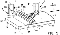
- Figure 5 shows the situation in which the gripper 5 is still in a gripping state, gripping the tape 40.
- the foil collection unit 6 With the gripper 5 holding the removed part 24 of the protective foil 2 stationary with respect to the tire tread 1, the foil collection unit 6 is positioned by its corresponding displacement drive 64 in the entry position at the protective foil 2 just behind or downstream of the one end 23 of the protective foil 2 and/or the tape 40 with respect to the removal direction X.
- the displacement drive 64 has moved the foil collection unit 6 from the entry position in the entry direction D into the winding position as shown in figure 5 .
- the pins 61, 62 are slid over and/or extend across the width of the protective foil 2 on both sides of the main surface of the protective foil 2.
- FIG 6 the situation is shown in which the gripping mechanism 53 has been operated to move the gripping jaws 51, 52 apart into the releasing state.
- the gripper drive 54 has subsequently moved the gripper 5 backwards in a retraction direction G away from the tape 40 and the protective foil 2.
- the forces exerted by the gripper 5 onto the tape 40 during the movement of the gripping jaws 51, 52 into the releasing state and/or the movement in the retraction direction G are greater than the adhesive bonding of the tape 40 to the gripping jaws 51, 52, thereby causing the tape 40 to detach from the gripping jaws 51, 52.
- the tape 40 is thus no longer gripped by the gripper 5 and the protective foil 2 is now supported and/or engaged by the foil collection unit 6.
- the winding drive 63 of the foil collection unit 6 may now be activated to rotate the pins 61, 62 in a winding rotation R about the winding axis S.
- Figure 7 shows the situation in which the winding drive 63 has rotated the pins 61, 62 over several revolutions or windings, thereby causing the tape 40 and the removed part 24 of the protective foil 2 to coil up or wind up around the pins 61, 62.
- the tape 40 is first wound against one of the pins 61, 62, after which the subsequent windings cause the downstream, still uncollected removed part 24 of the protective foil 2 to be wound up around the pins 61, 62 and the tape 40 already wound thereon.
- the subsequent windings of the protective foil 2 will stick to the tape 40, thereby ensuring that the downstream removed part 24 of the protective foil 2 sticks to and is wound onto the pins 61, 62.
- the protective foil 2 is securely engaged by the foil collection unit 6.
- the corresponding displacement drive 64 is arranged for moving the foil collection unit 6 in a removal direction X parallel to the longitudinal direction L of the tire tread 1 and/or perpendicular to the winding axis S, thereby gradually pulling and removing a greater part 24 of the protective foil 2 from the tire tread 1 in the removal direction X and reducing the remaining part 25 of the protective foil 2.
- the displacement drive 64 is arranged for moving the foil collection unit 6 in the removal direction X up to and/or a short distance beyond the other end of the protective foil 2 and/or the other end of the tire tread 1 to enable the foil collection unit 6 to collect and wind-up the entire protective foil 2.
- the foil collection unit 6 is moved at a velocity in the removal direction X that is sufficient to stay ahead or upstream of the fold at the transition from the removed part 24 and the remaining part 25 of the protective foil 2.
- the velocity in the removal direction X is chosen to be at least the same as, substantially the same as or dependent on the velocity at which the protective foil 2 is collected onto the foil collection unit 6.
- the distance that the foil collection unit 6 moves over time in the removal direction X is substantially equal to the circumferential length of each winding of the protective foil 2 on the foil collection unit 2 over the same amount of time. In this manner, the length of the uncollected, removed part 24 between the foil collection unit 6 and the remaining part 25 of the protective foil 2 remains substantially constant.
- slacking of the uncollected, removed part 24 between the foil collection unit 6 and the remaining part 25 of the protective foil 2 is to be reduced to an amount which does not allow the removed part 24 to contact the remaining part 25.
- the tire tread 1 can be moved relative to the foil collection unit 6 in the direction T opposite to the removal direction X on the conveyor 9, thereby effectively moving the foil collection unit 6 relative to the tire tread 1 in the removal direction X.
- the wound up protective foil 2 may be scraped off from the pins 61, 62.
- the protective foil 2 is disposed as waste and/or may be recycled.
Landscapes
- Engineering & Computer Science (AREA)
- Mechanical Engineering (AREA)
- Tyre Moulding (AREA)
- Folding Of Thin Sheet-Like Materials, Special Discharging Devices, And Others (AREA)
Description
- The invention relates to a foil removal device and a method for removing a protective foil from a tire tread.
- Tire treads are usually provided with a protective foil on the application side. This protective foil needs to be removed prior to application of the tire tread to a tire carcass. Currently, the protective foil is manually removed. The removal is a time consuming process which dominates the tire tread application cycle time. Furthermore, the protective foil tears easily and is hard and heavy to be consistently removed by hand. Finally, any manual intervention during or after removal of the protective foil is likely to damage or contaminate the exposed application side of the tire tread.
-
JP 2011 189678 A claims - It is an object of the present invention to provide a foil removal device and a method for removing a protective foil from a tire tread, which at least partially solves one or more of the aforementioned drawbacks of manual removal.
- According to a first aspect, the invention provides a foil removal device for removing a foil from a tire tread in a removal direction, wherein the foil removal device comprises a foil collection unit with a winding element for collecting the foil and a winding drive for driving the winding element in a winding rotation about a winding axis, wherein the winding element is arranged for receiving the foil at or near one of the ends of the foil, wherein the foil removal device further comprises a gripper that is arranged for engaging the foil in a gripping position at or near the one end of the foil prior to the removal of the foil and a gripper drive that is arranged for moving the gripper from the gripping position towards the foil collection unit to partially remove the foil from the tire tread, wherein the gripper is arranged for releasing the removed part of the foil when the foil collection unit has received the removed part of the foil at or near the one end of the foil, wherein, after receiving the removed part of the foil, the winding drive is arranged for driving the winding element over several revolutions to engage and subsequently remove the foil by winding the foil around the winding element over several revolutions about the winding axis, wherein the removal device comprises a displacement drive that is arranged for moving the foil collection unit relative to the tire tread in the removal direction simultaneously with the winding drive driving the winding element.
- Tire treads are typically sufficiently long such that a single length can be applied circumferentially and spliced around the circumference of a carcass. Removal of the foil by simply pulling the foil in the removal direction would require the foil to be pulled from one end of the tire tread until far beyond the other, opposite end of the tire tread. The increasing length of the part of the foil that is being removed would be subject to slacking, which could potentially cause the removed part of the foil to contact the remaining part of the foil that is still attached to the tire tread, thereby causing unpredictable behavior during the removal of the foil. To prevent the slack in the removed part of the foil from contacting the remaining part of the tire tread, the removed part of the foil would have to be lifted higher and higher into the air to provide enough clearance underneath the slack. The invention not only automates the removal of the foil, it also solves the abovementioned problem specifically related to the removal of foil from lengthy tire treads. The gripper according to the invention can engage and peel off a part of the foil, which removed part can subsequently be securely transferred from the gripper to the foil collection unit. By winding the foil and simultaneously moving the foil collection unit in the removal direction or the tire tread in the opposite direction, the foil can be removed by pulling on the foil in the removal direction while at the same time, the length of the removed part of the foil can be collected at the foil collection unit to prevent or reduce slacking in the removed, uncollected part of the foil.
- In an embodiment the foil removal device further comprises a gripper that is arranged for engaging the foil in a gripping position at or near the one end of the foil prior to the removal of the foil and a gripper drive that is arranged for moving the gripper from the gripping position towards the foil collection unit to partially remove the foil from the tire tread, wherein the gripper is arranged for releasing the removed part of the foil when the foil collection unit has received the removed part of the foil at or near the one end of the foil. The gripper can engage and peel off a part of the foil, which removed part can subsequently be securely transferred from the gripper to the foil collection unit.
- In an embodiment the gripper drive, during the movement of the gripper from the gripping position towards the foil collection unit, is arranged for rotating the gripper in a flipping rotation about a flipping axis transverse or perpendicular to the removal direction and/or parallel to the surface of the foil over an angle in the range of one-hundred to one-hundred-and-sixty degrees. During the flipping of the gripper, the engaged, removed part of the foil is taken along and flipped or rotated about the same flipping axis, such that the removed part of the foil can subsequently be pulled in the removal direction by the foil collection unit.
- In an embodiment the gripper drive is arranged for moving the gripper in the removal direction beyond the foil collection unit and wherein the foil collection unit is arranged for engaging the removed part of the foil in the removal direction behind the gripper. With the foil collection unit engaging behind the gripper, the foil collection unit can securely engage the foil at the one end thereof, without the gripper hindering said engagement.
- In an embodiment the removal device further comprises a tape applicator and a tape applicator drive for driving the tape applicator in an application direction, wherein the tape applicator is arranged for applying a tape in the application direction with a first part thereof in adhesive contact with the one end of the foil and a second part thereof projecting freely from the foil, wherein the gripper is arranged for indirectly engaging the foil through gripping of the freely extending, second part of the tape. By indirectly engaging the foil through gripping of the tape, it can be prevented that the gripper damages the tire tread and/or the foil.
- In a preferred embodiment the application direction is transverse or perpendicular to the removal direction. Thus, the tape can be applied along the one end, transverse or perpendicular to the removal direction. This is typically parallel to the shortest, transverse side of the foil. Thus a minimum length of tape is required for the removal, thereby reducing the amount of waste during the removal.
- In an embodiment the tape applicator is arranged for holding a supply of tape that is substantially longer the length of the tape that is applied to the foil, wherein the foil removal device is provided with a cutter for cutting off the tape from the supply of tape. The tape applicator can thus provide a plurality of lengths of tape, for subsequent cycles of removal. As the tape is cut at a definitive length, the amount of tape used to remove the foil can be kept to a minimum, thereby reducing the amount of waste during the removal.
- In an embodiment the cutter is arranged for cutting off the tape from the supply of tape when the tape, in the application direction, is applied to a substantial part of the foil and preferably the entire foil. By applying the tape along a substantial part of the foil, the forces exerted by the gripper on the tape can be equally distributed over the foil, thereby increasing the consistency of the removal and preventing tears in the foil and/or the tape.
- In an embodiment the gripper is provided with two opposing jaws which are arranged for gripping, in the application direction, a substantial part of the tape and preferably the entire tape. By having the opposing jaws of the gripper extend along and/or grip a substantial part of the foil, the forces exerted by the gripper on the tape can be equally distributed over the tape and indirectly over the foil, thereby increasing the consistency of the removal and preventing tears in the foil and/or the tape.
- In an embodiment the foil collection unit is arranged for receiving the foil at or near the one end thereof that is adjacent to the tape. The combined weight of the foil and the tape can cause the one end of the foil to bend downwards on the opposite side of the winding element with respect to the remaining part of the foil, thereby reducing the chances that the foil releases from the winding element. Furthermore, the combined thickness of the tape and the foil may be greater than the distance between the pins of the winding element, thereby preventing the foil from being retracted backwards in a direction opposite to the removal direction.
- In an embodiment the tape applicator comprises a sensor for detecting the position of the one end of the foil and for sending signals indicative of the detected position to the tape applicator drive to control the tape applicator to move into an application position for the application along the application direction. The sensor can further automate the application of the tape, regardless of the possibly varying characteristics of the tire tread.
- In an embodiment the tape is arranged to be applied to the foil by adhesive bonding. The adhesive bonding allows for the tape to stick to the foil such that forces exerted on the tape by the gripper can be transferred to the foil.
- In an embodiment the displacement drive is arranged for moving the foil collection unit relative to the tire tread in the removal direction at least at the same velocity and preferably substantially at the same velocity at which the foil is wound on the winding element. In this manner, the length of the uncollected, removed part of the foil can be kept constant or can be reduced, thereby preventing or reducing slacking.
- In a preferred embodiment the winding element comprises two mutually parallel pins, wherein the pins are spaced apart for receiving the foil in between the pins at or near the one end of the foil.
- In an embodiment the foil collection unit is movable in an entry direction transverse to the removal direction into a winding position in which the pins are slid over the foil on both sides of the main surface of the foil.
- In an embodiment the displacement drive, preferably an XY-drive system, is arranged to move the foil collection unit. In an alternative embodiment the displacement drive is a conveyor that is arranged for supporting and displacing the tire tread relative to the foil collection unit in a direction opposite to the removal direction.
- According to a second aspect, the invention provides a Method for removing a foil from a tire tread in a removal direction with the use of a foil removal device, wherein the foil removal device comprises a foil collection unit with a winding element for collecting the foil and a winding drive for driving the winding element in a winding rotation about a winding axis, wherein the foil removal device further comprises a gripper and a gripper drive, wherein the method comprises the steps of engaging the foil with the gripper in a gripping position at or near the one end of the foil prior to the removal of the foil, moving the gripper with the gripper drive from the gripping position towards the foil collection unit to partially remove the foil from the tire tread, receiving the foil at the winding element at or near one of the ends of the foil, releasing the removed part of the foil from the gripper when the foil collection unit has received the removed part of the foil at or near the one end of the foil, subsequently engaging and removing the foil by having the winding drive driving the winding element over several revolutions to engage and subsequently remove the foil by winding the foil around the winding element over several revolutions about the winding axis, wherein the removal device comprises a displacement drive, wherein the method further comprises the step of moving the foil collection unit relative to the tire tread in the removal direction simultaneously with the winding drive driving the winding element.
- The gripper can engage and peel off a part of the foil, which removed part can subsequently be securely transferred from the gripper to the foil collection unit. By winding the foil and simultaneously moving the foil collection unit in the removal direction or the tire tread in the opposite direction, the foil can be removed by pulling on the foil in the removal direction while at the same time, the length of the removed part of the foil can be collected at the foil collection unit to prevent or reduce slacking in the removed, uncollected part of the foil.
- In an embodiment the gripper drive, during the movement of the gripper from the gripping position towards the foil collection unit, rotates the gripper in a flipping rotation about a flipping axis transverse or perpendicular to the removal direction and/or parallel to the surface of the foil over an angle in the range of one-hundred to one-hundred-and-sixty degrees. During the flipping of the gripper, the engaged, removed part of the foil is taken along and flipped or rotated about the same flipping axis, such that the removed part of the foil can subsequently be pulled in the removal direction by the foil collection unit.
- In an embodiment the gripper drive moves the gripper in the removal direction beyond the foil collection unit, wherein the foil collection unit engages the removed part of the foil in the removal direction behind the gripper. With the foil collection unit engaging behind the gripper, the foil collection unit can securely engage the foil at the one end thereof, without the gripper hindering said engagement.
- In an embodiment the foil collection unit is moved in an entry direction transverse to the removal direction into a winding position in which the pins are slid over the foil on both sides of the main surface of the foil.
- In an embodiment the removal device further comprises a tape applicator and a tape applicator drive for driving the tape applicator in an application direction, wherein the method further comprises the steps of applying a tape with the tape applicator in the application direction with a first part of the tape in adhesive contact with the one end of the foil and a second part of the tape projecting freely from the foil, wherein the gripper is engages the foil through gripping of the freely extending, second part of the tape. By indirectly engaging the foil through gripping of the tape, it can be prevented that the gripper damages the tire tread and/or the foil.
- In a preferred embodiment the application direction is transverse or perpendicular to the removal direction. Thus, the tape can be applied along the one end, transverse or perpendicular to the removal direction. This is typically parallel to the shortest, transverse side of the foil. Thus a minimum length of tape is required for the removal, thereby reducing the amount of waste during the removal.
- In an embodiment the tape applicator holds a supply of tape that is substantially longer the length of the tape that is being applied to the foil, wherein the foil removal device is provided with a cutter, wherein the method comprises the step of cutting off the tape from the supply of tape after application to the foil. The tape applicator can thus provide a plurality of lengths of tape, for subsequent cycles of removal. As the tape is cut at a definitive length, the amount of tape used to remove the foil can be kept to a minimum, thereby reducing the amount of waste during the removal.
- In an embodiment the foil collection unit receives the foil at or near the one end thereof that is adjacent to the tape. The combined weight of the foil and the tape can cause the one end of the foil to bend downwards on the opposite side of the winding element with respect to the remaining part of the foil, thereby reducing the chances that the foil releases from the winding element. Furthermore, the combined thickness of the tape and the foil may be greater than the distance between the pins of the winding element, thereby preventing the foil from being retracted backwards in a direction opposite to the removal direction.
- In an embodiment the tape applicator comprises a sensor, wherein the method comprises the steps of detecting the position of the one end of the foil with the sensor, wherein the sensor sends signals indicative of the detected position to the tape applicator drive, wherein the tape applicator drive controls the tape applicator to move into an application position for the subsequent application along the application direction based on the signals. The sensor can further automate the application of the tape, regardless of the possibly varying characteristics of the tire tread.
- In an embodiment the displacement drive moves the foil collection unit relative to the tire tread in the removal direction at least at the same velocity and preferably substantially at the same velocity at which the foil is being wound on the winding element. In this manner, the length of the uncollected, removed part of the foil can be kept constant or can be reduced, thereby preventing or reducing slacking.
- The various aspects and features described and shown in the specification can be applied, individually, wherever possible. These individual aspects, in particular the aspects and features described in the attached dependent claims, can be made subject of divisional patent applications.
- The invention will be elucidated on the basis of an exemplary embodiment shown in the attached schematic drawings, in which:
-
figure 1 shows a view in perspective of a tire tread with a protective foil; -
figure 2 shows a view in perspective the tire tread according tofigure 1 and a tape applicator for applying a length of tape to the protective foil on the tire tread; -
figures 3 and 4 show a side view and a view in perspective, respectively, of the tire tread and the tape according tofigure 2 and a gripper for gripping the tape and for flipping and partially removing the protective foil from the tire tread; and -
figures 5 ,6 and 7 show a view in perspective and two side views, respectively, of the tire tread and the partially removed tape according tofigure 4 and a foil collection unit for removing and collection the remainder of the protective foil. -
Figure 1 shows anelongate tire tread 1 for circumferential application to or retreading of a tire or a tire carcass (not shown). Thetire tread 1 comprises an outer surface or runningsurface 11 which, after application, is facing radially outwards to be in contact with a road. Thetire tread 1 further comprises anapplication side 12 which, after application, faces radially inwards and is applied or attached to the tire carcass. Thetire tread 1 is provided with twolongitudinal sides tire tread 1, considered in the longitudinal direction L, has two transverse ends or edges that form the leading end and the trailing end of thetire tread 1 during application. Only oneend 15 of the two ends is shown infigure 1 . It is observed that removal of the protective foil can start at any of the two ends. - As shown in
figure 1 , a foil, in particular a protective film orprotective foil 2 is provided on theapplication side 12 of thetire tread 1. Theprotective foil 2 protects theapplication side 12 of thetire tread 1 from contaminations, damage or unintended sticking to other (similar) tire components. The stickiness or tackiness of the uncured rubber material of thetire tread 1 prevents theprotective foil 2 from being easily removed from theapplication side 12. Theprotective foil 2 has twolongitudinal sides tire tread 1, only oneend 23 of the two ends of theprotective foil 2 is shown infigure 1 . Theprotective foil 2 is arranged on theapplication side 12 in an orientation with itslongitudinal sides longitudinal sides tire tread 1. The oneend 23 is arranged parallel to, alongside and/or close to the oneend 15 of the tire tread. Preferably, the surface area of theprotective foil 2 covers at least 30-40% of the surface area of theapplication side 12 to optimize the protection thereof. In this example, the surface area of theprotective foil 2 covers a substantial part, preferably at least 80% of the surface area of theapplication side 12 -
Figures 2-7 show the foil removal device according to the invention, for removing theprotective foil 2 from thetire tread 1 in a removal direction X. - As shown in
figure 2 , the foil removal device comprises atape applicator 3 with a supply oftape 4. Thetape applicator 3 is arranged to be movable with respect to thetire tread 1 via atape applicator drive 31, e.g. an XY-drive system which is known per se, in a tape application direction B along the oneend 23 of theprotective foil 2, perpendicular to the longitudinal direction L of thetire tread 1 and the removal direction X. During the movement along the tape application direction B, thetape applicator 3 applies a length oftape 40 from the supply oftape 4 to said oneend 23 of theprotective foil 2. Thetape applicator 3 is arranged for applying the length oftape 40 such that, when considered in the longitudinal direction L of thetire tread 1 and the removal direction X, afirst part 41 of the length oftape 40 is applied to the oneend 23 of theprotective foil 2 and a remainingsecond part 42 of the length oftape 40 extends or projects freely beyond the contour or outside of theprotective foil 2 at the oneend 23 thereof. Preferably, the remainingsecond part 42 of the length oftape 40, when considered in the longitudinal direction L of thetire tread 1 and the removal direction X, also extends or projects freely beyond the contour of or outside of thetire tread 1 at the oneend 15 thereof. The length oftape 40 is provided with at least oneadhesive side 43, which is adhesive at least at thefirst part 41 of the length oftape 40 that is in contact with theprotective foil 2 at application. Preferably, the length oftape 40 is adhesive on both sides. - Optionally, the
tape applicator 3 is provided with asensor 32 for detecting the position of the oneend 23 of theprotective foil 2 and for sending signals indicative of said detected position to the drive of thetape applicator 3 to control thetape applicator 3 to move into an application position for the aforementioned application along the application direction B. - After application of the length of
tape 40 to theprotective foil 2 by thetape applicator 3, the length oftape 40 is cut off from the supply of thetape 4 by an automatic cutter (schematically shown by scissors C infigure 2 ). The length oftape 40 shall hereafter be referred to as thetape 40. The length of thetape 40, in the application direction B, substantially corresponds to the width of theprotective foil 2 between the twolongitudinal sides - As shown in
figures 3-6 , the foil removal device further comprises agripper 5 for engaging theprotective foil 2 through gripping of thetape 40 at the oneend 23 of theprotective foil 2. Thegripper 5 is provided with two opposing claws orjaws mechanism 53 between a closed, gripping state as shown infigures 3 and 4 and an open, releasing state as shown infigure 6 . Optionally, the grippingjaws tape 40 to the grippingjaws figures 4 and5 , the opposingjaws figure 2 ) over a substantial part, and in this example the entire width of thetape 40 or of theprotective foil 2 between the twolongitudinal sides end 23 thereof. As shown infigure 4 , thegripper 5 is arranged to be movable with respect to thetire tread 1 via agripper drive 54, e.g. an XY-drive system with a rotatable mounting for thegripper 5, in a rotation in a flipping direction F about a flipping axis K. The flipping axis K extends parallel to or in theapplication side 12 of thetire tread 1, transverse or perpendicular to the longitudinal direction L of thetire tread 1. Optionally, thetape applicator 3 and thegripper 5 are supported on and/or driven by the same XY-drive system. - Preferably, the
gripper 5 is rotated in the flipping direction F over an angle in the range one-hundred degrees to one-hundred-and-sixty degrees with respect to the horizontal orientation of thegripper 5 as shown infigure 3 . In particular, thegripper 5 is not rotated over a full one-hundred-and-eighty degrees to prevent folding theprotective foil 2 back onto itself. - As shown in
figures 5 ,6 and 7 , the foil removal device further comprises afoil collection unit 6 for removal and collection of theprotective foil 2. Thefoil collection unit 6 comprises a winding element in the form of two mutuallyparallel pins tire tread 1 and the removal direction X. Thepins protective foil 2 and/or thetape 40, and in particular the thickness thereof, to pass or to be received in between the twopins foil collection unit 6 is provided with a windingdrive 63 for driving thepins pins pins protective foil 2 and/or thetape 40 in between. - The
foil collection unit 6 is provided with or coupled to adisplacement drive 64, preferably in the form of an XY- or XYZ-drive system which is known per se, which is arranged to move thefoil collection unit 6 relative to thetire tread 1 in the entry direction D into a winding position as shown infigure 5 , and in the removal direction X as shown infigures 6 and 7 . Alternatively, thetire tread 1 is arranged on a displacement drive 9, preferably in the form of a conveyor (known per se), which is arranged to move thetire tread 1 relative to thefoil collection unit 6 in a direction T opposite to the removal direction X, such that - in effect - thefoil collection unit 6 is moved in the removal direction X with respect to thetire tread 1. - The method for removing the
protective foil 2 from thetire tread 1 with the use of the aforementioned foil removal device will be elucidated below with reference tofigures 2-7 . - In
figure 2 , the situation is shown in which thetape applicator 3 has been moved by the tape applicator drive in the application direction B along the oneend 23 of theprotective foil 2. During the movement of thetape applicator 3 along the oneend 23 of theprotective foil 2, thetape applicator 3 has applied a length oftape 40, which has been subsequently cut-off by cutter C. The resulting cut-offtape 40 has afirst part 41 that is applied by adhesion to the oneend 23 of theprotective foil 2 and a second, remainingpart 42 which extends or projects outside theprotective foil 2 and thetire tread 1 at the respective ends 23, 15 thereof. - Next, in
figure 3 , thegripper 5 is introduced and driven by the correspondinggripper drive 54 into a substantially horizontal gripping position opposite to the projectingsecond part 42 of thetape 40. In the situation as shown infigure 3 , the grippingmechanism 53 of thegripper 5 has been actuated to move the grippingjaws second part 42 of thetape 40 from opposite sides. Thegripper 5 has now indirectly engaged theprotective foil 2 through gripping of thetape 40. Thegripper 5 is subsequently moved by the correspondinggripper drive 54 over a rotation in the flipping direction F about the flipping axis K into a flipped position as shown infigure 4 . - During the rotation in the flipping direction F, the
gripper 5 has taken along, pulled, peeled or removed the grippedtape 40 and indirectly apart 24 of theprotective foil 2 from thetire tread 1 in the removal direction X. Thetape 40 and said removedpart 24 of theprotective foil 2 are flipped about the flipping axis K, thereby folding the removedpart 24 of theprotective foil 2 in the removal direction X and backwards with respect to the direction of the remainingpart 25 of theprotective foil 2 that is still applied to thetire tread 1. The rotation of thegripper 5 in the flipping direction F is stopped at a maximum angle of one-hundred-and-sixty degrees such that the slack in the removedpart 24 of theprotective foil 2 does not contact the remainingpart 25 of theprotective foil 2. -
Figure 5 shows the situation in which thegripper 5 is still in a gripping state, gripping thetape 40. With thegripper 5 holding the removedpart 24 of theprotective foil 2 stationary with respect to thetire tread 1, thefoil collection unit 6 is positioned by itscorresponding displacement drive 64 in the entry position at theprotective foil 2 just behind or downstream of the oneend 23 of theprotective foil 2 and/or thetape 40 with respect to the removal direction X. Thedisplacement drive 64 has moved thefoil collection unit 6 from the entry position in the entry direction D into the winding position as shown infigure 5 . In the winding position, thepins protective foil 2 on both sides of the main surface of theprotective foil 2. - In
figure 6 , the situation is shown in which thegripping mechanism 53 has been operated to move the grippingjaws gripper drive 54 has subsequently moved thegripper 5 backwards in a retraction direction G away from thetape 40 and theprotective foil 2. The forces exerted by thegripper 5 onto thetape 40 during the movement of the grippingjaws tape 40 to the grippingjaws tape 40 to detach from the grippingjaws tape 40 is thus no longer gripped by thegripper 5 and theprotective foil 2 is now supported and/or engaged by thefoil collection unit 6. The windingdrive 63 of thefoil collection unit 6 may now be activated to rotate thepins -
Figure 7 shows the situation in which the windingdrive 63 has rotated thepins tape 40 and the removedpart 24 of theprotective foil 2 to coil up or wind up around thepins tape 40 is first wound against one of thepins part 24 of theprotective foil 2 to be wound up around thepins tape 40 already wound thereon. Depending on the direction in which thetape 40 is wound, or if thetape 40 is adhesive on both sides, the subsequent windings of theprotective foil 2 will stick to thetape 40, thereby ensuring that the downstream removedpart 24 of theprotective foil 2 sticks to and is wound onto thepins protective foil 2 is securely engaged by thefoil collection unit 6. - During or simultaneously with the winding, the
corresponding displacement drive 64 is arranged for moving thefoil collection unit 6 in a removal direction X parallel to the longitudinal direction L of thetire tread 1 and/or perpendicular to the winding axis S, thereby gradually pulling and removing agreater part 24 of theprotective foil 2 from thetire tread 1 in the removal direction X and reducing the remainingpart 25 of theprotective foil 2. In particular, thedisplacement drive 64 is arranged for moving thefoil collection unit 6 in the removal direction X up to and/or a short distance beyond the other end of theprotective foil 2 and/or the other end of thetire tread 1 to enable thefoil collection unit 6 to collect and wind-up the entireprotective foil 2. Thefoil collection unit 6 is moved at a velocity in the removal direction X that is sufficient to stay ahead or upstream of the fold at the transition from the removedpart 24 and the remainingpart 25 of theprotective foil 2. Preferably, the velocity in the removal direction X is chosen to be at least the same as, substantially the same as or dependent on the velocity at which theprotective foil 2 is collected onto thefoil collection unit 6. Thus, the distance that thefoil collection unit 6 moves over time in the removal direction X is substantially equal to the circumferential length of each winding of theprotective foil 2 on thefoil collection unit 2 over the same amount of time. In this manner, the length of the uncollected, removedpart 24 between thefoil collection unit 6 and the remainingpart 25 of theprotective foil 2 remains substantially constant. In particular, slacking of the uncollected, removedpart 24 between thefoil collection unit 6 and the remainingpart 25 of theprotective foil 2 is to be reduced to an amount which does not allow the removedpart 24 to contact the remainingpart 25. - Instead of moving the
foil collection unit 6 in the removal direction X, thetire tread 1 can be moved relative to thefoil collection unit 6 in the direction T opposite to the removal direction X on the conveyor 9, thereby effectively moving thefoil collection unit 6 relative to thetire tread 1 in the removal direction X. - After the
protective foil 2 has been fully removed and collected fromtire tread 1, the wound upprotective foil 2 may be scraped off from thepins protective foil 2 is disposed as waste and/or may be recycled. - It is to be understood that the above description is included to illustrate the operation of the preferred embodiments and is not meant to limit the scope of the invention. From the above discussion, many variations will be apparent to one skilled in the art that would yet be encompassed by the scope of the present invention.
Claims (20)
- Foil removal device for removing a foil (2) from a tire tread (1) in a removal direction (X), wherein the foil removal device comprises a foil collection unit (6) with a winding element (61, 62) for collecting the foil (2) and a winding drive (63) for driving the winding element in a winding rotation (R) about a winding axis (S), characterized in that the winding element (61, 62) is arranged for receiving the foil (2) at or near one of the ends (23) of the foil (2), wherein the foil removal device further comprises a gripper (5) that is arranged for engaging the foil (2) in a gripping position at or near the one end (23) of the foil (2) prior to the removal of the foil (2) and a gripper drive (54) that is arranged for moving the gripper (5) from the gripping position towards the foil collection unit (6) to partially remove the foil (2) from the tire tread (1), wherein the gripper (5) is arranged for releasing the removed part of the foil (2) when the foil collection unit (6) has received the removed part of the foil (2) at or near the one end (23) of the foil (2), wherein, after receiving the removed part of the foil (2), the winding drive (63) is arranged for driving the winding element (61, 62) over several revolutions to engage and subsequently remove the foil (2) by winding the foil (2) around the winding element (61, 62) over several revolutions about the winding axis (S), wherein the removal device comprises a displacement drive (9, 64) that is arranged for moving the foil collection unit (6) relative to the tire tread (1) in the removal direction (X) simultaneously with the winding drive (63) driving the winding element (61, 62).
- Foil removal device according to claim 1, wherein the gripper drive (54), during the movement of the gripper (5) from the gripping position towards the foil collection unit (6), is arranged for rotating the gripper (5) in a flipping rotation (F) about a flipping axis (K) transverse or perpendicular to the removal direction (X) and/or parallel to the surface of the foil (2) over an angle in the range of one-hundred to one-hundred-and-sixty degrees.
- Foil removal device according to claim 1 or 2, wherein the gripper drive (54) is arranged for moving the gripper (5) in the removal direction (X) beyond the foil collection unit (6) and wherein the foil collection unit (6) is arranged for engaging the removed part of the foil (2) in the removal direction (X) behind the gripper (5).
- Foil removal device according to any one of the preceding claims, wherein the removal device further comprises a tape applicator (3) and a tape applicator drive (31) for driving the tape applicator (3) in an application direction (B), wherein the tape applicator (3) is arranged for applying a tape (40) in the application direction (B) with a first part (41) thereof in adhesive contact with the one end (23) of the foil (2) and a second part (42) thereof projecting freely from the foil (2), wherein the gripper (5) is arranged for indirectly engaging the foil (2) through gripping of the freely extending, second part (42) of the tape (40), preferably wherein the application direction is transverse or perpendicular to the removal direction.
- Foil removal device according to claim 4, wherein the tape applicator (3) is arranged for holding a supply of tape (40) that is substantially longer the length of the tape (40) that is applied to the foil (2), wherein the foil removal device is provided with a cutter (C) for cutting off the tape (40) from the supply of tape (40), preferably wherein the cutter (C) is arranged for cutting off the tape (40) from the supply of tape (40) when the tape (40), in the application direction (B), is applied to a substantial part of the foil (2) and preferably the entire foil (2), more preferably wherein the gripper (5) is provided with two opposing jaws (51, 52) which are arranged for gripping, in the application direction (B), a substantial part of the tape (40) and preferably the entire tape (40).
- Foil removal device according to claim 4 or 5, wherein the foil collection unit (6) is arranged for receiving the foil (2) at or near the one end (23) thereof that is adjacent to the tape (40).
- Foil removal device according to any one of claims 4-6, wherein the tape applicator (3) comprises a sensor (32) for detecting the position of the one end (23) of the foil (2) and for sending signals indicative of the detected position to the tape applicator drive (31) to control the tape applicator (3) to move into an application position for the application along the application direction (B).
- Foil removal device according to any one of claims 4-7, wherein the tape (40) is arranged to be applied to the foil (2) by adhesive bonding.
- Foil removal device according to anyone of the preceding claims, wherein the displacement drive (9, 64) is arranged for moving the foil collection unit (6) relative to the tire tread (1) in the removal direction (X) at least at the same velocity and preferably substantially at the same velocity at which the foil (2) is wound on the winding element (61, 62).
- Foil removal device according to any one of the preceding claims, wherein the winding element (61, 62) comprises two mutually parallel pins (61, 62), wherein the pins (61, 62) are spaced apart for receiving the foil (2) in between the pins (61, 62) at or near the one end (23) of the foil (2), preferably wherein the foil collection unit (6) is movable in an entry direction (D) transverse to the removal direction (X) into a winding position in which the pins (61, 62) are slid over the foil (2) on both sides of the main surface of the foil (2).
- Foil removal device according to any one of the preceding claims, wherein the displacement drive (9, 64), preferably an XY-drive system, is arranged to move the foil collection unit (6).
- Foil removal device according to any one of claims 1-10, wherein the displacement drive (9) is a conveyor (9) that is arranged for supporting and displacing the tire tread (1) relative to the foil collection unit (6) in a direction opposite to the removal direction (X).
- Method for removing a foil (2) from a tire tread (1) in a removal direction (X) with the use of a foil removal device, wherein the foil removal device comprises a foil collection unit (6) with a winding element (61, 62) for collecting the foil (2) and a winding drive (63) for driving the winding element (61, 62) in a winding rotation (R) about a winding axis (S), characterized in that the foil removal device further comprises a gripper (5) and a gripper drive (54), wherein the method comprises the steps of engaging the foil (2) with the gripper (5) in a gripping position at or near the one end (23) of the foil (2) prior to the removal of the foil (2), moving the gripper (5) with the gripper drive (54) from the gripping position towards the foil collection unit (6) to partially remove the foil (2) from the tire tread (1), receiving the foil (2) at the winding element (61, 62) at or near one of the ends (23) of the foil (2), releasing the removed part of the foil (2) from the gripper (5) when the foil collection unit (6) has received the removed part of the foil (2) at or near the one end (23) of the foil (2), subsequently engaging and removing the foil (2) by having the winding drive (63) driving the winding element (61, 62) over several revolutions to engage and subsequently remove the foil (2) by winding the foil (2) around the winding element (61, 62) over several revolutions about the winding axis (S), wherein the removal device comprises a displacement drive (64), wherein the method further comprises the step of moving the foil collection unit (6) relative to the tire tread (1) in the removal direction (X) simultaneously with the winding drive (64) driving the winding element (61, 62).
- Method according to claim 13, wherein the gripper drive (54), during the movement of the gripper (5) from the gripping position towards the foil collection unit (6), rotates the gripper (5) in a flipping rotation (F) about a flipping axis (K) transverse or perpendicular to the removal direction (X) and/or parallel to the surface of the foil (2) over an angle in the range of one-hundred to one-hundred-and-sixty degrees.
- Method according to claim 13 or 14, wherein the gripper drive (54) moves the gripper (5) in the removal direction (X) beyond the foil collection unit (6), wherein the foil collection unit (6) engages the removed part of the foil (2) in the removal direction (X) behind the gripper (5), preferably wherein the wherein the foil collection unit (6) is moved in an entry direction (D) transverse to the removal direction (X) into a winding position in which the pins (61, 62) are slid over the foil on both sides of the main surface of the foil (2).
- Method according to any one of claims 13-15, wherein the removal device further comprises a tape applicator (3) and a tape applicator drive (31) for driving the tape applicator (3) in an application direction (B), wherein the method further comprises the steps of applying a tape (40) with the tape applicator (3) in the application direction (B) with a first part (41) of the tape (40) in adhesive contact with the one end (23) of the foil (2) and a second part (42) of the tape (40) projecting freely from the foil (2), wherein the gripper (5) is engages the foil (2) through gripping of the freely extending, second part (42) of the tape (40), preferably wherein the application direction (B) is transverse or perpendicular to the removal direction (X).
- Method according to claim 16, wherein the tape applicator (3) holds a supply of tape (40) that is substantially longer the length of the tape (40) that is being applied to the foil (2), wherein the foil removal device is provided with a cutter (C), wherein the method comprises the step of cutting off the tape (40) from the supply of tape (40) after application to the foil (2).
- Method according to claim 16 or 17, wherein the foil collection unit (6) receives the foil (2) at or near the one end (23) thereof that is adjacent to the tape (40).
- Method according to any one of claims 16-18, wherein the tape applicator (3) comprises a sensor (32), wherein the method comprises the steps of detecting the position of the one end (23) of the foil (2) with the sensor (32), wherein the sensor (32) sends signals indicative of the detected position to the tape applicator drive (31), wherein the tape applicator drive (31) controls the tape applicator (3) to move into an application position for the subsequent application along the application direction (B) based on the signals.
- Method according to any one of claims 13-19, wherein the displacement drive (9, 64) moves the foil collection unit (6) relative to the tire tread (1) in the removal direction (X) at least at the same velocity and preferably substantially at the same velocity at which the foil (2) is being wound on the winding element (61, 62).
Priority Applications (2)
| Application Number | Priority Date | Filing Date | Title |
|---|---|---|---|
| RS20200760A RS60474B1 (en) | 2014-04-23 | 2015-03-19 | Foil removal device and a method for removing a foil from a tire tread |
| PL15715500T PL3134340T3 (en) | 2014-04-23 | 2015-03-19 | Foil removal device and a method for removing a foil from a tire tread |
Applications Claiming Priority (2)
| Application Number | Priority Date | Filing Date | Title |
|---|---|---|---|
| NL2012668A NL2012668B1 (en) | 2014-04-23 | 2014-04-23 | Foil removal device and a method for removing a foil from a tire tread. |
| PCT/NL2015/050179 WO2015163756A1 (en) | 2014-04-23 | 2015-03-19 | Foil removal device and a method for removing a foil from a tire tread |
Publications (2)
| Publication Number | Publication Date |
|---|---|
| EP3134340A1 EP3134340A1 (en) | 2017-03-01 |
| EP3134340B1 true EP3134340B1 (en) | 2020-04-29 |
Family
ID=51358032
Family Applications (1)
| Application Number | Title | Priority Date | Filing Date |
|---|---|---|---|
| EP15715500.3A Active EP3134340B1 (en) | 2014-04-23 | 2015-03-19 | Foil removal device and a method for removing a foil from a tire tread |
Country Status (13)
| Country | Link |
|---|---|
| US (1) | US9902584B2 (en) |
| EP (1) | EP3134340B1 (en) |
| JP (1) | JP6495935B2 (en) |
| KR (1) | KR102107047B1 (en) |
| CN (1) | CN106232396B (en) |
| BR (1) | BR112016021955B1 (en) |
| ES (1) | ES2790359T3 (en) |
| HU (1) | HUE050005T2 (en) |
| NL (1) | NL2012668B1 (en) |
| PL (1) | PL3134340T3 (en) |
| RS (1) | RS60474B1 (en) |
| RU (1) | RU2675487C2 (en) |
| WO (1) | WO2015163756A1 (en) |
Families Citing this family (24)
| Publication number | Priority date | Publication date | Assignee | Title |
|---|---|---|---|---|
| US10434683B2 (en) * | 2015-09-28 | 2019-10-08 | Converter Manufacturing, Llc | Apparatus for facilitating peeling of lined containers |
| IT201600078059A1 (en) * | 2016-07-26 | 2018-01-26 | I M A Industria Macch Automatiche S P A In Sigla Ima S P A | OPENING GROUP FOR PACKAGING |
| CN106865305B (en) * | 2017-04-27 | 2019-02-15 | 无锡百立德自动化有限公司 | High frequency start-stop trailer system |
| US10647102B2 (en) * | 2017-07-06 | 2020-05-12 | General Electric Company | System and method for removal of a layer |
| CN107265157B (en) * | 2017-08-02 | 2023-03-10 | 海安苏州大学先进机器人研究院 | Folding propelling movement all-in-one of filter bag |
| CN107585611B (en) * | 2017-08-25 | 2019-11-05 | 浙江汇锋塑胶科技有限公司 | A kind of cutting structure of film cutting winder |
| KR102424743B1 (en) * | 2017-10-13 | 2022-07-26 | 삼성디스플레이 주식회사 | Protecting film peeling device and peeling method for the same |
| CN107662835A (en) * | 2017-10-26 | 2018-02-06 | 天津天重中直科技工程有限公司 | A kind of strip automatic clip distribution apparatus |
| JP6916223B2 (en) * | 2019-01-30 | 2021-08-11 | 日機装株式会社 | Peeling device |
| KR102812431B1 (en) * | 2019-06-17 | 2025-05-27 | 삼성디스플레이 주식회사 | Apparatus of manufacturing for display device and method of manufacturing for display device |
| CN111689291A (en) * | 2020-06-30 | 2020-09-22 | 江苏海狮机械股份有限公司 | Moving platform for cloth spreading machine |
| IT202000015748A1 (en) * | 2020-06-30 | 2021-12-30 | Bridgestone Europe Nv Sa | METHOD AND APPLICATION UNIT FOR APPLYING A SOUNDPROOFING MATERIAL INTO AN INTERNAL CAVITY OF A TIRE |
| KR20220058688A (en) * | 2020-10-29 | 2022-05-10 | 삼성디스플레이 주식회사 | Apparatus for manufaturing display device and method for manufacturing display device |
| KR102895321B1 (en) | 2020-11-05 | 2025-12-05 | 삼성디스플레이 주식회사 | Film peeling device and method of peeling film |
| JP7609651B2 (en) * | 2021-02-16 | 2025-01-07 | 株式会社ディスコ | Peeling device |
| US20240075732A1 (en) * | 2021-02-23 | 2024-03-07 | Beijing Boe Sensor Technology Co., Ltd. | Peeling system and peeling method for flexible fingerprint component |
| CN113291906B (en) * | 2021-03-02 | 2022-12-06 | 阿里巴巴(中国)有限公司 | Garment web gripping device, component, placement table and related method |
| JP7576380B2 (en) * | 2021-04-15 | 2024-10-31 | エルジー エナジー ソリューション リミテッド | Roll-type material supply device |
| US11505457B2 (en) * | 2021-04-16 | 2022-11-22 | Xintec Inc. | Semiconductor removing apparatus and operation method thereof |
| KR102326503B1 (en) * | 2021-07-20 | 2021-11-15 | (주)도원위즈테크 | Material peeling device of winding type material roll |
| CN113911488B (en) * | 2021-10-21 | 2023-03-14 | 深圳市智显科技有限公司 | Novel LCD tears membrane mechanism again after pasting polaroid |
| NL2033183B1 (en) * | 2022-09-29 | 2024-04-08 | Firma Plat | Device for automatically rolling up and unrolling an elongated cloth |
| US12552572B2 (en) * | 2023-02-13 | 2026-02-17 | Parata Systems, Llc | Cutting and rolling device for use with pharmaceutical pouch packaging |
| CN119262919A (en) * | 2024-10-29 | 2025-01-07 | 宿迁奇瓦丽科技发展有限公司 | A packaging device for decorative paintings with cutting function |
Family Cites Families (33)
| Publication number | Priority date | Publication date | Assignee | Title |
|---|---|---|---|---|
| SU1367173A1 (en) * | 1985-09-17 | 1988-01-15 | Предприятие П/Я А-1507 | Device for removing protective film from flat backing |
| JPH08309880A (en) * | 1995-05-24 | 1996-11-26 | Bridgestone Corp | Molding method for raw tire for regenerated tire |
| JP3529197B2 (en) * | 1995-07-17 | 2004-05-24 | 横浜ゴム株式会社 | Sheet material bonding method and apparatus |
| JPH09123305A (en) * | 1995-11-02 | 1997-05-13 | Yokohama Rubber Co Ltd:The | Method for tearing protective sheet from rubber sheet material and apparatus therefor |
| JP3299462B2 (en) * | 1996-11-25 | 2002-07-08 | 住友ゴム工業株式会社 | Winding method and winding device for unvulcanized rubber body |
| US6149758A (en) * | 1997-06-20 | 2000-11-21 | Lintec Corporation | Sheet removing apparatus and method |
| JP2000063036A (en) * | 1998-08-26 | 2000-02-29 | Kansei Corp | Peeling method for protective film and device therefor |
| NL1016431C2 (en) * | 2000-10-18 | 2002-04-22 | Univ Nijmegen | Method for separating a film and a substrate. |
| JP3925183B2 (en) * | 2001-12-14 | 2007-06-06 | 日本ゼオン株式会社 | Automatic peeling apparatus and peeling method for packaging film for elastomer material |
| KR20080072183A (en) * | 2007-02-01 | 2008-08-06 | 삼성전자주식회사 | Film peeling apparatus and method |
| JP5305604B2 (en) * | 2007-03-16 | 2013-10-02 | 株式会社東芝 | Adhesive film peeling apparatus and liquid crystal panel manufacturing method |
| JP2008230717A (en) * | 2007-03-16 | 2008-10-02 | Toshiba Corp | Adhesive film peeling apparatus and liquid crystal panel manufacturing method |
| KR20080089730A (en) * | 2007-04-02 | 2008-10-08 | 삼성전자주식회사 | Apparatus and method for removing polarizer |
| US20110005660A1 (en) * | 2007-09-05 | 2011-01-13 | Yuichiro Ogawa | Method and apparatus for manufacturing unvulcanized tires |
| US20090273796A1 (en) * | 2008-04-30 | 2009-11-05 | Kodak Graphic Communications Canada Company | Peeling imaged media from a substrate |
| EP2200811A1 (en) * | 2007-10-19 | 2010-06-30 | Kodak Graphic Communications Canada Company | Peeling imaged media from a substrate |
| JP5076989B2 (en) * | 2008-03-17 | 2012-11-21 | 横浜ゴム株式会社 | Labeling method and labeling support for tire |
| JP4740296B2 (en) * | 2008-08-28 | 2011-08-03 | リンテック株式会社 | Sheet peeling apparatus and peeling method |
| JP4740298B2 (en) * | 2008-09-04 | 2011-08-03 | リンテック株式会社 | Sheet peeling apparatus and peeling method |
| JP5423498B2 (en) * | 2010-03-16 | 2014-02-19 | 横浜ゴム株式会社 | Unvulcanized rubber material supply system |
| JP5584554B2 (en) * | 2010-08-13 | 2014-09-03 | アイエス・テクノロジー・ジャパン株式会社 | Seal peeling device |
| US8756783B2 (en) * | 2011-11-29 | 2014-06-24 | Shenzhen China Star Optoelectronics Technology Co., Ltd. | Method of fully, automatically removing a polarizer of an LCD panel |
| KR101392588B1 (en) * | 2012-09-06 | 2014-05-08 | 금호타이어 주식회사 | Cutter for Trimming of Tire Tread |
| CN103707531B (en) * | 2012-10-02 | 2018-01-12 | 住友橡胶工业株式会社 | Manufacture device, manufacture method, sticker and the method for attaching of rubber strip |
| ITBO20120581A1 (en) * | 2012-10-25 | 2014-04-26 | Marchesini Group Spa | METHOD TO REMOVE THE SEALING FILM FROM A CONTAINER AND A DEVICE THAT ACTIVATES THIS METHOD |
| JP5778116B2 (en) * | 2012-11-05 | 2015-09-16 | 日東電工株式会社 | Adhesive sheet attaching method and adhesive sheet attaching apparatus |
| EP2926955A4 (en) * | 2012-11-30 | 2016-07-27 | Yaskawa Denki Seisakusho Kk | Robotic system |
| KR20150127709A (en) * | 2013-03-15 | 2015-11-17 | 브리지스톤 반닥, 엘엘씨 | Methods for retreading tires employing tread composites made with dry-transfer cement composite |
| KR102069851B1 (en) * | 2013-03-26 | 2020-01-28 | 삼성디스플레이 주식회사 | Delamination apparatus and inline thermal imaging system |
| KR101584440B1 (en) * | 2013-06-18 | 2016-01-11 | 주식회사 엘지화학 | Thin polarizer, manufacturing method thereof, polarizing plate and display device comprising the same |
| KR102130153B1 (en) * | 2013-10-15 | 2020-07-06 | 삼성디스플레이 주식회사 | Apparatus of peeling film |
| WO2015170210A1 (en) * | 2014-05-03 | 2015-11-12 | Semiconductor Energy Laboratory Co., Ltd. | Separation apparatus for thin film stacked body |
| JP5982431B2 (en) * | 2014-06-27 | 2016-08-31 | 株式会社岩崎製作所 | Film peeling and winding method and apparatus |
-
2014
- 2014-04-23 NL NL2012668A patent/NL2012668B1/en not_active IP Right Cessation
-
2015
- 2015-03-19 RS RS20200760A patent/RS60474B1/en unknown
- 2015-03-19 WO PCT/NL2015/050179 patent/WO2015163756A1/en not_active Ceased
- 2015-03-19 JP JP2016556312A patent/JP6495935B2/en active Active
- 2015-03-19 BR BR112016021955-4A patent/BR112016021955B1/en active IP Right Grant
- 2015-03-19 EP EP15715500.3A patent/EP3134340B1/en active Active
- 2015-03-19 US US15/129,780 patent/US9902584B2/en active Active
- 2015-03-19 RU RU2016141328A patent/RU2675487C2/en active
- 2015-03-19 CN CN201580020901.XA patent/CN106232396B/en active Active
- 2015-03-19 ES ES15715500T patent/ES2790359T3/en active Active
- 2015-03-19 HU HUE15715500A patent/HUE050005T2/en unknown
- 2015-03-19 PL PL15715500T patent/PL3134340T3/en unknown
- 2015-03-19 KR KR1020167027929A patent/KR102107047B1/en active Active
Non-Patent Citations (1)
| Title |
|---|
| None * |
Also Published As
| Publication number | Publication date |
|---|---|
| RU2675487C2 (en) | 2018-12-19 |
| US9902584B2 (en) | 2018-02-27 |
| JP6495935B2 (en) | 2019-04-03 |
| EP3134340A1 (en) | 2017-03-01 |
| BR112016021955A2 (en) | 2017-08-15 |
| NL2012668A (en) | 2016-02-03 |
| CN106232396B (en) | 2018-02-23 |
| JP2017513731A (en) | 2017-06-01 |
| BR112016021955B1 (en) | 2021-09-28 |
| ES2790359T3 (en) | 2020-10-27 |
| HUE050005T2 (en) | 2020-11-30 |
| KR20160145570A (en) | 2016-12-20 |
| RS60474B1 (en) | 2020-08-31 |
| NL2012668B1 (en) | 2016-07-04 |
| RU2016141328A3 (en) | 2018-10-25 |
| PL3134340T3 (en) | 2020-10-19 |
| WO2015163756A1 (en) | 2015-10-29 |
| CN106232396A (en) | 2016-12-14 |
| US20170158449A1 (en) | 2017-06-08 |
| KR102107047B1 (en) | 2020-05-08 |
| RU2016141328A (en) | 2018-05-23 |
Similar Documents
| Publication | Publication Date | Title |
|---|---|---|
| EP3134340B1 (en) | Foil removal device and a method for removing a foil from a tire tread | |
| RU2696455C2 (en) | Method and installation for automatic application of noise suppressing element on tire for wheels of vehicles | |
| JP6563509B2 (en) | Method and apparatus for installing and installing a strip in a tire | |
| US10833493B2 (en) | Device and method for removing a sheath of electrical conductors | |
| RU2751858C2 (en) | Method and apparatus for applying noise-reducing elements to a tyre for vehicle wheels | |
| US10913229B2 (en) | Method and installation for winding a rubber strip onto a form of revolution | |
| RS57404B1 (en) | Glazing panel removal device and method | |
| EP3052310B1 (en) | Method for picking up and placing tire components on a transfer drum | |
| WO2014204299A1 (en) | Apparatus and method for butt joining strip-shaped members | |
| EP3562772B1 (en) | Device for continuous production of coils of wound strips | |
| EP3619154B1 (en) | Device and method for winding and transferring a tape from a full reel onto an empty reel | |
| EP2747990B1 (en) | Tyre layer application assembly and method | |
| CN115042263A (en) | Steel wire rope core separation method for conveying belt | |
| JP4698370B2 (en) | Method for peeling ductile strip from release sheet and apparatus used therefor | |
| JP4590807B2 (en) | Method and apparatus for laminating sheet material | |
| JP4889527B2 (en) | Small roll device | |
| EP4622796A1 (en) | Machine for the automated transfer of a liner material from a first support to a second support | |
| JP5209104B2 (en) | Small roll device | |
| CN105460678A (en) | Adhesive piece supplying device and supplying method | |
| JP6324819B2 (en) | Apparatus and method for forming annular member | |
| JP6402039B2 (en) | Rubber strip unwinding device |
Legal Events
| Date | Code | Title | Description |
|---|---|---|---|
| STAA | Information on the status of an ep patent application or granted ep patent |
Free format text: STATUS: THE INTERNATIONAL PUBLICATION HAS BEEN MADE |
|
| PUAI | Public reference made under article 153(3) epc to a published international application that has entered the european phase |
Free format text: ORIGINAL CODE: 0009012 |
|
| STAA | Information on the status of an ep patent application or granted ep patent |
Free format text: STATUS: REQUEST FOR EXAMINATION WAS MADE |
|
| 17P | Request for examination filed |
Effective date: 20160906 |
|
| AK | Designated contracting states |
Kind code of ref document: A1 Designated state(s): AL AT BE BG CH CY CZ DE DK EE ES FI FR GB GR HR HU IE IS IT LI LT LU LV MC MK MT NL NO PL PT RO RS SE SI SK SM TR |
|
| AX | Request for extension of the european patent |
Extension state: BA ME |
|
| DAV | Request for validation of the european patent (deleted) | ||
| DAX | Request for extension of the european patent (deleted) | ||
| STAA | Information on the status of an ep patent application or granted ep patent |
Free format text: STATUS: EXAMINATION IS IN PROGRESS |
|
| 17Q | First examination report despatched |
Effective date: 20190305 |
|
| GRAP | Despatch of communication of intention to grant a patent |
Free format text: ORIGINAL CODE: EPIDOSNIGR1 |
|
| STAA | Information on the status of an ep patent application or granted ep patent |
Free format text: STATUS: GRANT OF PATENT IS INTENDED |
|
| INTG | Intention to grant announced |
Effective date: 20191024 |
|
| GRAS | Grant fee paid |
Free format text: ORIGINAL CODE: EPIDOSNIGR3 |
|
| GRAA | (expected) grant |
Free format text: ORIGINAL CODE: 0009210 |
|
| STAA | Information on the status of an ep patent application or granted ep patent |
Free format text: STATUS: THE PATENT HAS BEEN GRANTED |
|
| AK | Designated contracting states |
Kind code of ref document: B1 Designated state(s): AL AT BE BG CH CY CZ DE DK EE ES FI FR GB GR HR HU IE IS IT LI LT LU LV MC MK MT NL NO PL PT RO RS SE SI SK SM TR |
|
| REG | Reference to a national code |
Ref country code: GB Ref legal event code: FG4D |
|
| REG | Reference to a national code |
Ref country code: CH Ref legal event code: EP |
|
| REG | Reference to a national code |
Ref country code: AT Ref legal event code: REF Ref document number: 1262999 Country of ref document: AT Kind code of ref document: T Effective date: 20200515 |
|
| REG | Reference to a national code |
Ref country code: DE Ref legal event code: R096 Ref document number: 602015051597 Country of ref document: DE |
|
| REG | Reference to a national code |
Ref country code: IE Ref legal event code: FG4D Ref country code: NL Ref legal event code: FP |
|
| REG | Reference to a national code |
Ref country code: FI Ref legal event code: FGE |
|
| REG | Reference to a national code |
Ref country code: SK Ref legal event code: T3 Ref document number: E 34334 Country of ref document: SK |
|
| REG | Reference to a national code |
Ref country code: LT Ref legal event code: MG4D |
|
| REG | Reference to a national code |
Ref country code: ES Ref legal event code: FG2A Ref document number: 2790359 Country of ref document: ES Kind code of ref document: T3 Effective date: 20201027 |
|
| PG25 | Lapsed in a contracting state [announced via postgrant information from national office to epo] |
Ref country code: IS Free format text: LAPSE BECAUSE OF FAILURE TO SUBMIT A TRANSLATION OF THE DESCRIPTION OR TO PAY THE FEE WITHIN THE PRESCRIBED TIME-LIMIT Effective date: 20200829 Ref country code: PT Free format text: LAPSE BECAUSE OF FAILURE TO SUBMIT A TRANSLATION OF THE DESCRIPTION OR TO PAY THE FEE WITHIN THE PRESCRIBED TIME-LIMIT Effective date: 20200831 Ref country code: GR Free format text: LAPSE BECAUSE OF FAILURE TO SUBMIT A TRANSLATION OF THE DESCRIPTION OR TO PAY THE FEE WITHIN THE PRESCRIBED TIME-LIMIT Effective date: 20200730 Ref country code: LT Free format text: LAPSE BECAUSE OF FAILURE TO SUBMIT A TRANSLATION OF THE DESCRIPTION OR TO PAY THE FEE WITHIN THE PRESCRIBED TIME-LIMIT Effective date: 20200429 Ref country code: NO Free format text: LAPSE BECAUSE OF FAILURE TO SUBMIT A TRANSLATION OF THE DESCRIPTION OR TO PAY THE FEE WITHIN THE PRESCRIBED TIME-LIMIT Effective date: 20200729 Ref country code: SE Free format text: LAPSE BECAUSE OF FAILURE TO SUBMIT A TRANSLATION OF THE DESCRIPTION OR TO PAY THE FEE WITHIN THE PRESCRIBED TIME-LIMIT Effective date: 20200429 |
|
| REG | Reference to a national code |
Ref country code: AT Ref legal event code: MK05 Ref document number: 1262999 Country of ref document: AT Kind code of ref document: T Effective date: 20200429 |
|
| PG25 | Lapsed in a contracting state [announced via postgrant information from national office to epo] |
Ref country code: BG Free format text: LAPSE BECAUSE OF FAILURE TO SUBMIT A TRANSLATION OF THE DESCRIPTION OR TO PAY THE FEE WITHIN THE PRESCRIBED TIME-LIMIT Effective date: 20200729 Ref country code: LV Free format text: LAPSE BECAUSE OF FAILURE TO SUBMIT A TRANSLATION OF THE DESCRIPTION OR TO PAY THE FEE WITHIN THE PRESCRIBED TIME-LIMIT Effective date: 20200429 Ref country code: HR Free format text: LAPSE BECAUSE OF FAILURE TO SUBMIT A TRANSLATION OF THE DESCRIPTION OR TO PAY THE FEE WITHIN THE PRESCRIBED TIME-LIMIT Effective date: 20200429 |
|
| REG | Reference to a national code |
Ref country code: HU Ref legal event code: AG4A Ref document number: E050005 Country of ref document: HU |
|
| PG25 | Lapsed in a contracting state [announced via postgrant information from national office to epo] |
Ref country code: AL Free format text: LAPSE BECAUSE OF FAILURE TO SUBMIT A TRANSLATION OF THE DESCRIPTION OR TO PAY THE FEE WITHIN THE PRESCRIBED TIME-LIMIT Effective date: 20200429 |
|
| PG25 | Lapsed in a contracting state [announced via postgrant information from national office to epo] |
Ref country code: DK Free format text: LAPSE BECAUSE OF FAILURE TO SUBMIT A TRANSLATION OF THE DESCRIPTION OR TO PAY THE FEE WITHIN THE PRESCRIBED TIME-LIMIT Effective date: 20200429 Ref country code: SM Free format text: LAPSE BECAUSE OF FAILURE TO SUBMIT A TRANSLATION OF THE DESCRIPTION OR TO PAY THE FEE WITHIN THE PRESCRIBED TIME-LIMIT Effective date: 20200429 Ref country code: EE Free format text: LAPSE BECAUSE OF FAILURE TO SUBMIT A TRANSLATION OF THE DESCRIPTION OR TO PAY THE FEE WITHIN THE PRESCRIBED TIME-LIMIT Effective date: 20200429 Ref country code: AT Free format text: LAPSE BECAUSE OF FAILURE TO SUBMIT A TRANSLATION OF THE DESCRIPTION OR TO PAY THE FEE WITHIN THE PRESCRIBED TIME-LIMIT Effective date: 20200429 |
|
| REG | Reference to a national code |
Ref country code: DE Ref legal event code: R097 Ref document number: 602015051597 Country of ref document: DE |
|
| PLBE | No opposition filed within time limit |
Free format text: ORIGINAL CODE: 0009261 |
|
| STAA | Information on the status of an ep patent application or granted ep patent |
Free format text: STATUS: NO OPPOSITION FILED WITHIN TIME LIMIT |
|
| 26N | No opposition filed |
Effective date: 20210201 |
|
| PG25 | Lapsed in a contracting state [announced via postgrant information from national office to epo] |
Ref country code: SI Free format text: LAPSE BECAUSE OF FAILURE TO SUBMIT A TRANSLATION OF THE DESCRIPTION OR TO PAY THE FEE WITHIN THE PRESCRIBED TIME-LIMIT Effective date: 20200429 |
|
| PG25 | Lapsed in a contracting state [announced via postgrant information from national office to epo] |
Ref country code: MC Free format text: LAPSE BECAUSE OF FAILURE TO SUBMIT A TRANSLATION OF THE DESCRIPTION OR TO PAY THE FEE WITHIN THE PRESCRIBED TIME-LIMIT Effective date: 20200429 |
|
| REG | Reference to a national code |
Ref country code: CH Ref legal event code: PL |
|
| REG | Reference to a national code |
Ref country code: BE Ref legal event code: MM Effective date: 20210331 |
|
| PG25 | Lapsed in a contracting state [announced via postgrant information from national office to epo] |
Ref country code: CH Free format text: LAPSE BECAUSE OF NON-PAYMENT OF DUE FEES Effective date: 20210331 Ref country code: LI Free format text: LAPSE BECAUSE OF NON-PAYMENT OF DUE FEES Effective date: 20210331 Ref country code: IE Free format text: LAPSE BECAUSE OF NON-PAYMENT OF DUE FEES Effective date: 20210319 |
|
| PG25 | Lapsed in a contracting state [announced via postgrant information from national office to epo] |
Ref country code: BE Free format text: LAPSE BECAUSE OF NON-PAYMENT OF DUE FEES Effective date: 20210331 |
|
| P01 | Opt-out of the competence of the unified patent court (upc) registered |
Effective date: 20230517 |
|
| PG25 | Lapsed in a contracting state [announced via postgrant information from national office to epo] |
Ref country code: CY Free format text: LAPSE BECAUSE OF FAILURE TO SUBMIT A TRANSLATION OF THE DESCRIPTION OR TO PAY THE FEE WITHIN THE PRESCRIBED TIME-LIMIT Effective date: 20200429 |
|
| PG25 | Lapsed in a contracting state [announced via postgrant information from national office to epo] |
Ref country code: MK Free format text: LAPSE BECAUSE OF FAILURE TO SUBMIT A TRANSLATION OF THE DESCRIPTION OR TO PAY THE FEE WITHIN THE PRESCRIBED TIME-LIMIT Effective date: 20200429 |
|
| PG25 | Lapsed in a contracting state [announced via postgrant information from national office to epo] |
Ref country code: MT Free format text: LAPSE BECAUSE OF FAILURE TO SUBMIT A TRANSLATION OF THE DESCRIPTION OR TO PAY THE FEE WITHIN THE PRESCRIBED TIME-LIMIT Effective date: 20200429 |
|
| PGFP | Annual fee paid to national office [announced via postgrant information from national office to epo] |
Ref country code: LU Payment date: 20250204 Year of fee payment: 11 |
|
| PGFP | Annual fee paid to national office [announced via postgrant information from national office to epo] |
Ref country code: DE Payment date: 20250205 Year of fee payment: 11 |
|
| PGFP | Annual fee paid to national office [announced via postgrant information from national office to epo] |
Ref country code: NL Payment date: 20250304 Year of fee payment: 11 Ref country code: RO Payment date: 20250314 Year of fee payment: 11 Ref country code: FI Payment date: 20250210 Year of fee payment: 11 |
|
| PGFP | Annual fee paid to national office [announced via postgrant information from national office to epo] |
Ref country code: HU Payment date: 20250206 Year of fee payment: 11 |
|
| PGFP | Annual fee paid to national office [announced via postgrant information from national office to epo] |
Ref country code: CZ Payment date: 20250221 Year of fee payment: 11 Ref country code: PL Payment date: 20250122 Year of fee payment: 11 Ref country code: FR Payment date: 20250210 Year of fee payment: 11 |
|
| PGFP | Annual fee paid to national office [announced via postgrant information from national office to epo] |
Ref country code: SK Payment date: 20250123 Year of fee payment: 11 Ref country code: IT Payment date: 20250306 Year of fee payment: 11 Ref country code: GB Payment date: 20250205 Year of fee payment: 11 |
|
| PGFP | Annual fee paid to national office [announced via postgrant information from national office to epo] |
Ref country code: RS Payment date: 20250122 Year of fee payment: 11 |
|
| PGFP | Annual fee paid to national office [announced via postgrant information from national office to epo] |
Ref country code: TR Payment date: 20250210 Year of fee payment: 11 |
|
| PGFP | Annual fee paid to national office [announced via postgrant information from national office to epo] |
Ref country code: ES Payment date: 20250401 Year of fee payment: 11 |