EP3134270B1 - Mitigating damage to drop generators in a printing system - Google Patents
Mitigating damage to drop generators in a printing system Download PDFInfo
- Publication number
- EP3134270B1 EP3134270B1 EP14890282.8A EP14890282A EP3134270B1 EP 3134270 B1 EP3134270 B1 EP 3134270B1 EP 14890282 A EP14890282 A EP 14890282A EP 3134270 B1 EP3134270 B1 EP 3134270B1
- Authority
- EP
- European Patent Office
- Prior art keywords
- drop generators
- image
- drop
- section
- Prior art date
- Legal status (The legal status is an assumption and is not a legal conclusion. Google has not performed a legal analysis and makes no representation as to the accuracy of the status listed.)
- Active
Links
Images



Classifications
-
- B—PERFORMING OPERATIONS; TRANSPORTING
- B41—PRINTING; LINING MACHINES; TYPEWRITERS; STAMPS
- B41J—TYPEWRITERS; SELECTIVE PRINTING MECHANISMS, i.e. MECHANISMS PRINTING OTHERWISE THAN FROM A FORME; CORRECTION OF TYPOGRAPHICAL ERRORS
- B41J2/00—Typewriters or selective printing mechanisms characterised by the printing or marking process for which they are designed
- B41J2/005—Typewriters or selective printing mechanisms characterised by the printing or marking process for which they are designed characterised by bringing liquid or particles selectively into contact with a printing material
- B41J2/01—Ink jet
- B41J2/015—Ink jet characterised by the jet generation process
- B41J2/04—Ink jet characterised by the jet generation process generating single droplets or particles on demand
- B41J2/045—Ink jet characterised by the jet generation process generating single droplets or particles on demand by pressure, e.g. electromechanical transducers
- B41J2/04501—Control methods or devices therefor, e.g. driver circuits, control circuits
- B41J2/0451—Control methods or devices therefor, e.g. driver circuits, control circuits for detecting failure, e.g. clogging, malfunctioning actuator
-
- B—PERFORMING OPERATIONS; TRANSPORTING
- B41—PRINTING; LINING MACHINES; TYPEWRITERS; STAMPS
- B41J—TYPEWRITERS; SELECTIVE PRINTING MECHANISMS, i.e. MECHANISMS PRINTING OTHERWISE THAN FROM A FORME; CORRECTION OF TYPOGRAPHICAL ERRORS
- B41J29/00—Details of, or accessories for, typewriters or selective printing mechanisms not otherwise provided for
- B41J29/38—Drives, motors, controls or automatic cut-off devices for the entire printing mechanism
- B41J29/393—Devices for controlling or analysing the entire machine ; Controlling or analysing mechanical parameters involving printing of test patterns
-
- B—PERFORMING OPERATIONS; TRANSPORTING
- B41—PRINTING; LINING MACHINES; TYPEWRITERS; STAMPS
- B41J—TYPEWRITERS; SELECTIVE PRINTING MECHANISMS, i.e. MECHANISMS PRINTING OTHERWISE THAN FROM A FORME; CORRECTION OF TYPOGRAPHICAL ERRORS
- B41J2/00—Typewriters or selective printing mechanisms characterised by the printing or marking process for which they are designed
- B41J2/005—Typewriters or selective printing mechanisms characterised by the printing or marking process for which they are designed characterised by bringing liquid or particles selectively into contact with a printing material
- B41J2/01—Ink jet
- B41J2/015—Ink jet characterised by the jet generation process
- B41J2/04—Ink jet characterised by the jet generation process generating single droplets or particles on demand
- B41J2/045—Ink jet characterised by the jet generation process generating single droplets or particles on demand by pressure, e.g. electromechanical transducers
- B41J2/04501—Control methods or devices therefor, e.g. driver circuits, control circuits
- B41J2/04513—Control methods or devices therefor, e.g. driver circuits, control circuits for increasing lifetime
-
- B—PERFORMING OPERATIONS; TRANSPORTING
- B41—PRINTING; LINING MACHINES; TYPEWRITERS; STAMPS
- B41J—TYPEWRITERS; SELECTIVE PRINTING MECHANISMS, i.e. MECHANISMS PRINTING OTHERWISE THAN FROM A FORME; CORRECTION OF TYPOGRAPHICAL ERRORS
- B41J2/00—Typewriters or selective printing mechanisms characterised by the printing or marking process for which they are designed
- B41J2/005—Typewriters or selective printing mechanisms characterised by the printing or marking process for which they are designed characterised by bringing liquid or particles selectively into contact with a printing material
- B41J2/01—Ink jet
- B41J2/015—Ink jet characterised by the jet generation process
- B41J2/04—Ink jet characterised by the jet generation process generating single droplets or particles on demand
- B41J2/045—Ink jet characterised by the jet generation process generating single droplets or particles on demand by pressure, e.g. electromechanical transducers
- B41J2/04501—Control methods or devices therefor, e.g. driver circuits, control circuits
- B41J2/04536—Control methods or devices therefor, e.g. driver circuits, control circuits using history data
-
- B—PERFORMING OPERATIONS; TRANSPORTING
- B41—PRINTING; LINING MACHINES; TYPEWRITERS; STAMPS
- B41J—TYPEWRITERS; SELECTIVE PRINTING MECHANISMS, i.e. MECHANISMS PRINTING OTHERWISE THAN FROM A FORME; CORRECTION OF TYPOGRAPHICAL ERRORS
- B41J2/00—Typewriters or selective printing mechanisms characterised by the printing or marking process for which they are designed
- B41J2/005—Typewriters or selective printing mechanisms characterised by the printing or marking process for which they are designed characterised by bringing liquid or particles selectively into contact with a printing material
- B41J2/01—Ink jet
- B41J2/015—Ink jet characterised by the jet generation process
- B41J2/04—Ink jet characterised by the jet generation process generating single droplets or particles on demand
- B41J2/045—Ink jet characterised by the jet generation process generating single droplets or particles on demand by pressure, e.g. electromechanical transducers
- B41J2/04501—Control methods or devices therefor, e.g. driver circuits, control circuits
- B41J2/04573—Timing; Delays
-
- B—PERFORMING OPERATIONS; TRANSPORTING
- B41—PRINTING; LINING MACHINES; TYPEWRITERS; STAMPS
- B41J—TYPEWRITERS; SELECTIVE PRINTING MECHANISMS, i.e. MECHANISMS PRINTING OTHERWISE THAN FROM A FORME; CORRECTION OF TYPOGRAPHICAL ERRORS
- B41J2/00—Typewriters or selective printing mechanisms characterised by the printing or marking process for which they are designed
- B41J2/005—Typewriters or selective printing mechanisms characterised by the printing or marking process for which they are designed characterised by bringing liquid or particles selectively into contact with a printing material
- B41J2/01—Ink jet
- B41J2/015—Ink jet characterised by the jet generation process
- B41J2/04—Ink jet characterised by the jet generation process generating single droplets or particles on demand
- B41J2/045—Ink jet characterised by the jet generation process generating single droplets or particles on demand by pressure, e.g. electromechanical transducers
- B41J2/04501—Control methods or devices therefor, e.g. driver circuits, control circuits
- B41J2/0458—Control methods or devices therefor, e.g. driver circuits, control circuits controlling heads based on heating elements forming bubbles
-
- B—PERFORMING OPERATIONS; TRANSPORTING
- B41—PRINTING; LINING MACHINES; TYPEWRITERS; STAMPS
- B41J—TYPEWRITERS; SELECTIVE PRINTING MECHANISMS, i.e. MECHANISMS PRINTING OTHERWISE THAN FROM A FORME; CORRECTION OF TYPOGRAPHICAL ERRORS
- B41J2/00—Typewriters or selective printing mechanisms characterised by the printing or marking process for which they are designed
- B41J2/005—Typewriters or selective printing mechanisms characterised by the printing or marking process for which they are designed characterised by bringing liquid or particles selectively into contact with a printing material
- B41J2/01—Ink jet
- B41J2/015—Ink jet characterised by the jet generation process
- B41J2/04—Ink jet characterised by the jet generation process generating single droplets or particles on demand
- B41J2/045—Ink jet characterised by the jet generation process generating single droplets or particles on demand by pressure, e.g. electromechanical transducers
- B41J2/04501—Control methods or devices therefor, e.g. driver circuits, control circuits
- B41J2/04581—Control methods or devices therefor, e.g. driver circuits, control circuits controlling heads based on piezoelectric elements
-
- B—PERFORMING OPERATIONS; TRANSPORTING
- B41—PRINTING; LINING MACHINES; TYPEWRITERS; STAMPS
- B41J—TYPEWRITERS; SELECTIVE PRINTING MECHANISMS, i.e. MECHANISMS PRINTING OTHERWISE THAN FROM A FORME; CORRECTION OF TYPOGRAPHICAL ERRORS
- B41J2/00—Typewriters or selective printing mechanisms characterised by the printing or marking process for which they are designed
- B41J2/005—Typewriters or selective printing mechanisms characterised by the printing or marking process for which they are designed characterised by bringing liquid or particles selectively into contact with a printing material
- B41J2/01—Ink jet
- B41J2/015—Ink jet characterised by the jet generation process
- B41J2/04—Ink jet characterised by the jet generation process generating single droplets or particles on demand
- B41J2/045—Ink jet characterised by the jet generation process generating single droplets or particles on demand by pressure, e.g. electromechanical transducers
- B41J2/04501—Control methods or devices therefor, e.g. driver circuits, control circuits
- B41J2/04586—Control methods or devices therefor, e.g. driver circuits, control circuits controlling heads of a type not covered by groups B41J2/04575 - B41J2/04585, or of an undefined type
-
- B—PERFORMING OPERATIONS; TRANSPORTING
- B41—PRINTING; LINING MACHINES; TYPEWRITERS; STAMPS
- B41J—TYPEWRITERS; SELECTIVE PRINTING MECHANISMS, i.e. MECHANISMS PRINTING OTHERWISE THAN FROM A FORME; CORRECTION OF TYPOGRAPHICAL ERRORS
- B41J2/00—Typewriters or selective printing mechanisms characterised by the printing or marking process for which they are designed
- B41J2/005—Typewriters or selective printing mechanisms characterised by the printing or marking process for which they are designed characterised by bringing liquid or particles selectively into contact with a printing material
- B41J2/01—Ink jet
- B41J2/135—Nozzles
- B41J2/165—Prevention or detection of nozzle clogging, e.g. cleaning, capping or moistening for nozzles
- B41J2/16585—Prevention or detection of nozzle clogging, e.g. cleaning, capping or moistening for nozzles for paper-width or non-reciprocating print heads
-
- B—PERFORMING OPERATIONS; TRANSPORTING
- B41—PRINTING; LINING MACHINES; TYPEWRITERS; STAMPS
- B41J—TYPEWRITERS; SELECTIVE PRINTING MECHANISMS, i.e. MECHANISMS PRINTING OTHERWISE THAN FROM A FORME; CORRECTION OF TYPOGRAPHICAL ERRORS
- B41J2/00—Typewriters or selective printing mechanisms characterised by the printing or marking process for which they are designed
- B41J2/005—Typewriters or selective printing mechanisms characterised by the printing or marking process for which they are designed characterised by bringing liquid or particles selectively into contact with a printing material
- B41J2/01—Ink jet
- B41J2/21—Ink jet for multi-colour printing
- B41J2/2132—Print quality control characterised by dot disposition, e.g. for reducing white stripes or banding
- B41J2/2135—Alignment of dots
-
- B—PERFORMING OPERATIONS; TRANSPORTING
- B41—PRINTING; LINING MACHINES; TYPEWRITERS; STAMPS
- B41J—TYPEWRITERS; SELECTIVE PRINTING MECHANISMS, i.e. MECHANISMS PRINTING OTHERWISE THAN FROM A FORME; CORRECTION OF TYPOGRAPHICAL ERRORS
- B41J2/00—Typewriters or selective printing mechanisms characterised by the printing or marking process for which they are designed
- B41J2/005—Typewriters or selective printing mechanisms characterised by the printing or marking process for which they are designed characterised by bringing liquid or particles selectively into contact with a printing material
- B41J2/01—Ink jet
- B41J2/21—Ink jet for multi-colour printing
- B41J2/2132—Print quality control characterised by dot disposition, e.g. for reducing white stripes or banding
- B41J2/2146—Print quality control characterised by dot disposition, e.g. for reducing white stripes or banding for line print heads
Definitions
- Thermal ink-jet printing technology typically includes the repeated heating of resistors to fire ink through a plurality of nozzles onto a media.
- Piezoelectric printhead technology typically includes the repeated actuation of piezoelectric elements to fire ink through a plurality of nozzles onto a media.
- the firing elements e.g., resistors or piezoelectric elements, are arranged in printheads, in which the printheads are smaller in width than the media and are to be scanned across the media.
- the firing elements are activated at appropriate times as the printheads are scanned one or more times across the media to cause a desired image to be formed on the media.
- Printing during multiple scans across the media enables printing fluid to be deposited at their desired locations through any of a number of nozzles.
- an operational firing element may be used to deposit ink at a particular location in place of a defective firing element.
- the firing elements are arranged in printheads, in which the printheads are similar to or larger in width than the media.
- the firing elements are activated at appropriate times to cause printing fluid to be deposited at desired locations on the media during a single pass of either the printheads with respect to the media or the media with respect to the printheads.
- the printheads in page wide printers remain fixed while the media moves in a particular direction beneath the printheads.
- Document US5581284 discloses a method of extending the life of a printbar that comprises an error-hiding algorithm wherein, in case of failure of a nozzle, another nozzle is assigned to eject the drops to the nozzle in failure.
- data corresponding to an image to be printed on a media by the printing system may be accessed.
- the data may include data that has been processed for printing, e.g., processed through an imaging pipeline where the data is color mapped, halftoned, linearized, swath cut, etc.
- the plurality of drop generators may be controlled to print the image on the media while mitigating damage to the plurality of drop generators and without shifting placement of the image on the media or shifting the plurality of drop generators in a direction perpendicular to a feed direction of the media.
- Various manners in which damage to the plurality of drop generators may be mitigated are disclosed herein.
- a drop generator such as a piezoelectric element or a resistor
- a drop generator may be construed as being damaged if the drop generator has stopped functioning properly. That is, a drop generator may be construed as being damaged if the drop generator is unable to fire a drop of printing fluid through a nozzle or if the drop generator is only able to fire a drop of printing fluid that is relatively smaller than a nominally sized drop, i.e., a drop size corresponding to a properly functioning drop generator.
- a drop generator such as a resistor, may be construed as being damaged if the drop generator has been burned-in.
- burn-in of a drop generator may be defined as an uneven wearing of the drop generator as compared with other drop generators in the printing system, as may occur when the drop generator is used a significantly larger number of times as compared to the other drop generators to print portions of images. That is, a drop generator may experience "burn-in" or uneven wearing when that drop generator is activated much more often than neighboring drop generators.
- burn-in may be that the burnt-in drop generator(s) may be unable to eject a nominal or normal amount of printing fluid. This inability to cause a nominal amount of printing fluid to be ejected may cause the drop generator(s) to drop printing fluid that is sized differently than the printing fluids dropped by its neighboring drop generators.
- a burnt-in drop generator may drop a smaller sized drop of printing fluid or a larger sized drop of printing fluid than its neighboring drop generators.
- a burnt-in drop generator may drop a smaller sized drop of printing fluid or a larger sized drop of printing fluid than its neighboring drop generators.
- the same drop generators are responsible for printing along the same line in a feed direction of the media
- the drop generators are not a lighter or darker band
- the sections of an image printed by the damaged drop generators may appear as a lighter or darker band within the sections of the image printed by neighboring drop generators that have experienced a lesser degree of damage or are less worn.
- a set of drop generators may experience damage, e.g., burn-in, if the set of drop generators are employed to print relatively long lines in a feed direction of a media. This may occur in engineering drawings which often include long borders that extend from nearly one edge to an opposite edge of a media.
- damage to a plurality of drop generators may be mitigated through prevention or delay of the onset of the damage.
- the effects of the damage to the drop generators may be mitigated through drop generator control operations that may substantially avoid use of the damaged drop generators, for instance, to print filled in sections of images.
- the mitigation may be provided as an image processing pipeline solution in that the methods and the apparatuses disclosed herein may be implemented without shifting the placement of the image on the media or shifting a position of the drop generators in a direction that is perpendicular to the feed direction of the media. Instead, the mitigation may occur in the image processing pipeline of the printing system.
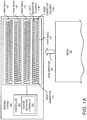
- FIG. 1A there is shown a simplified schematic diagram of a printing system 100, which may implement various aspects of the methods disclosed herein, according to an example. It should be understood that the printing system 100 depicted in FIG. 1A may include additional elements and that some of the elements depicted therein may be removed and/or modified without departing from a scope of the printing system 100.
- the printing system 100 may include a controller 102 and a number of print bars 106-112, which may equivalently be denoted as die, printheads, etc.
- the print bars 106-112 have been depicted as each including single components, the print bars 106-112 may instead be formed of multiple modules.
- Each of the print bars 106-112 may be supplied with different colored printing fluids, such as inks, dyes, etc., to be ejected from the print bars 106-112.
- a first print bar 106 may be supplied with a black colored printing fluid
- a second print bar 108 may be supplied with a cyan colored printing fluid
- a third print bar 110 may be supplied with a magenta colored printing fluid
- a fourth print bar 112 may be supplied with a yellow colored printing fluid.
- the printing system 100 may include additional print bars that are supplied with differently colored printing fluids and/or each of the print bars 106-112 may be formed of multiple modules.
- the printing system 100 may include a single print bar 106, for instance, that is to print a black colored printing fluid.
- Each of the print bars 106-112 is depicted as including a plurality of drop generators 114 arranged along two parallel columns.
- the drop generators 114 are depicted as being arranged along a first drop generator column 115a and a second drop generator column 115b.
- a relatively small number of drop generators 114 are shown for convenience, but it should be clearly understood that each of the print bars 106-112 may include much larger numbers of drop generators 114, for instance, to be able to print at 600 dpi or more across the width of a media 130.
- Each of the drop generators 114 may be a resistor (or equivalently, a heating element) or a piezoelectric element that may be individually activated or fired to cause drops of printing fluid to be ejected out of respective nozzles (an example is shown in FIG. 1B ).
- the drop generators 114 may be activated in any manner consistent with known heat generating or piezoelectric actuating drop generators and thus a detailed discussion of a manner in which the drop generators 114 may be activated to cause printing fluid to be ejected is not provided herein.
- the controller 102 also includes a damage mitigating apparatus 104 that is to mitigate damage to the drop generators 114.
- the damage mitigating apparatus 104 is to mitigate damage to the drop generators in printing an image on the media 130 while a file containing the image to be printed is in an image processing pipeline of the printing system 100.
- the damage mitigating apparatus 104 is to mitigate damage to the drop generators in printing the image without moving the drop generators 114 with respect to the media 130 in a direction perpendicular to the media 130 feed direction 132 or shifting placement of the image on the media 130.
- Various manners in which the damage mitigating apparatus 104 may mitigate damage to the drop generators 114 are discussed in detail below.
- the drop generators 114 are to drop printing fluid onto the media 130 as either the media 130 is fed past the print bars 106-112 in the feed direction 132 or the drop generators 114 are moved over the media 140 in a direction opposite the feed direction 132.
- any given location on the media 130 may receive printing fluid from the same drop generator 114 and thus, the printing system 100 may be a fixed printing system.
- the print bars 106-112 may not be scanned in a direction perpendicular to the feed direction 132.
- the print bars 106-112 may be moved slightly, e.g., half a nozzle width, during a printing operation to allow two-pass printing (one pass in each direction) at twice the resolution of single pass printing.
- the media 130 is fed in the feed direction 132
- the print bars 106-112 may equivalently be moved in the direction opposite the feed direction 132 without departing from a scope of the methods and apparatuses disclosed in the present disclosure.
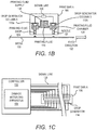
- FIG. 1B there is shown a simplified schematic diagram of a print bar 106, according to an example. It should be understood that the other print bars 108-112 may have similar configurations as the print bar 106 depicted in FIG. 1B . It should also be understood that the print bar 106 depicted in FIG. 1B may include additional elements and/or that the elements depicted therein may be removed and/or modified without departing from a scope of the print bar 106.
- the print bar 106 may include multiple drop generators 114, for instance, arranged along two substantially parallel columns 115a and 115b (two of the drop generators 114 are shown in FIG. 1B ).
- the drop generators 114 may receive printing fluid 116 from a printing fluid supply 118 that may be connected to a printing fluid reservoir (not shown).
- printing fluid 116 from the printing fluid supply 118 may be supplied into a printing fluid chamber (or equivalently, a firing chamber) 120 and activation of a drop generator 114 may cause a printing fluid drop 124 to be ejected through a nozzle 122 and onto the media 130.
- a printing fluid chamber or equivalently, a firing chamber
- the nozzles 122 on opposite sides of the printing fluid supply 118 may have approximately the same widths with respect to each other.
- the drop generator 114 is a resistor that is activated, e.g., heated, through receipt of an electrical signal through a signal line 126.
- the heating of the drop generator 114 may cause a bubble to be formed in the printing fluid 116 contained in the printing fluid chamber 120, which may cause a printing fluid drop 124 to be ejected through the nozzle 122.
- the drop generator 114 is a piezoelectric element that is activated through receipt of an electrical signal through a signal line 126.
- FIG. 1C A simplified example of a manner in which signal lines 126 may be connected between the controller 102 and the drop generators 114, according to an example, is depicted in FIG. 1C . It should, however, be understood that the controller 102 may control the transmission of electrical signals to each of the drop generators 114 through use of other mechanisms, for instance, multiplexers, etc.
- the controller 102 may selectively activate the drop generators 114 according to a proper sequence as the media 130 is fed in the feed direction 132 to cause printing fluid 116 to be dropped at the appropriate locations on the media 130 to form a desired image on the media 130.
- the desired image may include any of text, pictures, lines, drawings, filled-in drawings, etc.
- the controller 102, and particularly, the damage mitigating apparatus 104 may operate the drop generators 114 in any of a variety of manners to mitigate damage to the drop generators 114.
- FIG. 2 there is shown a simplified block diagram of the printing system 100, according to an example. It should be understood that the printing system 100 depicted in FIG. 2 may include additional elements and that some of the elements depicted therein may be removed and/or modified without departing from a scope of the printing system 100.
- the controller 102 is depicted as including, in addition to the damage mitigating apparatus 104, a processor 202, a signal line interface 204, and a data store 206.
- the damage mitigating apparatus 104 is also depicted as including a data accessing module 210, a damage mitigating module 212, and a drop generator controlling module 214.
- the controller 102 may further include an interface to a network connection, for instance, to enable the processor 202 to access data corresponding to images to be printed.
- the controller 102 may still further include an interface to an actuator (not shown) that is to control feeding of the media 130.
- the processor 202 which may be a microprocessor, a micro-controller, an application specific integrated circuit (ASIC), or the like, is to perform various processing functions in the controller 102.
- the processing functions may include invoking or implementing the damage mitigating apparatus 104 and particularly, the modules 210-214 of the damage mitigating apparatus 104, as discussed in greater detail herein below.
- the damage mitigating apparatus 104 is a hardware device on which is stored various sets of machine readable instructions.
- the damage mitigating apparatus 104 may be, for instance, a volatile or non-volatile memory, such as dynamic random access memory (DRAM), electrically erasable programmable read-only memory (EEPROM), magnetoresistive random access memory (MRAM), memristor, flash memory, floppy disk, a compact disc read only memory (CD-ROM), a digital video disc read only memory (DVD-ROM), or other optical or magnetic media, and the like, on which software may be stored.
- the modules 210-214 may be software modules, e.g., sets of machine readable instructions, stored in the damage mitigating apparatus 104.
- the damage mitigating apparatus 104 may be a hardware component, such as a chip, and the modules 210-214 may be hardware modules on the hardware component.
- the modules 210-214 may include a combination of software and hardware modules.
- the processor 202 may be an ASIC that is to perform the functions of the modules 210-214.
- the processor 202 and the damage mitigating apparatus 104 may be a single processing apparatus.
- the processor 202 may store data in the data store 206 and may use the data in implementing the modules 210-214. For instance, the processor 202 may store data pertaining to an image that is to be printed onto a medium 130.
- the data store 206 may be volatile and/or non-volatile memory, such as DRAM, EEPROM, MRAM, phase change RAM (PCRAM), memristor, flash memory, and the like.
- the data store 206 may be a device that may read from and write to a removable media, such as, a floppy disk, a CD-ROM, a DVD-ROM, or other optical or magnetic media.
- the signal line interface 204 may include hardware and/or software to enable the processor 202 to respectively send electrical signals to the drop generators 114 over signal lines 126. Although not shown, the signal line interface 204 may be connected to a power source from which the electrical signals may be transmitted to the respective drop generators 114. In addition, the processor 202 may be connected to an input/output interface (not shown) that may enable the processor 202 to access a network, such as an internal network, the Internet, etc., over which the processor 202 may receive files containing images to be printed.
- a network such as an internal network, the Internet, etc.
- the input/output interface may include a network interface card and/or may also include hardware and/or software to enable the processor 202 to communicate with various input and/or output devices, such as a keyboard, a mouse, a display, another computing device, etc., through which a user may input instructions into the printing system 100.
- various input and/or output devices such as a keyboard, a mouse, a display, another computing device, etc., through which a user may input instructions into the printing system 100.
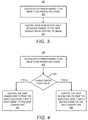
- FIGS. 3-9 depict flow diagrams of methods 300-900 for mitigating damage to a plurality of drop generators 114 in a printing system 100, according to various examples.
- the methods 300-900 may represent generalized illustrations and that other operations may be added or existing operations may be removed, modified, or rearranged without departing from the scopes of the methods 300-900.
- the processor 202 depicted in FIG. 2 may implement any of methods 300-900 through implementation of at least some of the modules 210-214.
- each of the methods 400-900 generally includes features that are more specific examples of the features contained in the method 300.
- data corresponding to an image to be printed on a media 130 may be accessed.
- data representing the image that has been processed for printing by the printing system to be printed may be stored in the data store 206.
- the data accessing module 210 may access the data from the data store 206.
- the data accessing module 210 may access the data from other sources, for instance, from an external data store over a local area network, over a wide area network, from an externally attached storage device, etc.
- the drop generators 114 may be controlled to print the image on the media while mitigating damage to the plurality of drop generators 114 and without shifting placement of the printed image on the media 130 or shifting the plurality of drop generators in a direction perpendicular to a feed direction of the media 130.
- the damage mitigating module 212 may determine how the drop generators 114 are to be operated to mitigate damage to the drop generators 114.
- the damage mitigating module 212 may determine which of the drop generators 114 are to be activated at which times for an image printing operation to cause the drop generators 114 to wear substantially evenly with respect to each other, without shifting placement of the printed image on the media 130 or shifting the drop generators 114 in a direction that is perpendicular to the feed of direction 132 of the media 130. That is, the damage mitigating module 212 may determine the timing at which selected drop generators 114 or groups of drop generators 114 are to be activated to print the image on the media 130 such that the margins between the edges of the media 130 and the printed image are sized as originally intended. In other words, therefore, the drop generator control while mitigating damage at block 304 may be achieved without printing the image with an entirely shifted set of drop generators 114.
- the drop generator controlling module 214 may control the drop generators 114 individually or in respective groups to drop printing fluid onto the media 130 at appropriate times while the media 130 is fed past the drop generators 114 to thus cause the image to be printed onto the media 130.
- the damage mitigating module 212 may make this determination and the drop generator controlling module 214 may control the drop generators 114 according to the determination are discussed in greater detail below with respect to the methods 400-900.
- the damage mitigating module 212 may determine that certain ones of the drop generators 114 are to be activated instead of other ones of the drop generators 114 in printing the image to thus cause the drop generators 114 to wear substantially evenly with respect to each other. In addition, the damage mitigating module 212 may make this determination such that the drop generators 114 wear substantially evenly with respect to each other over the course of printing a relatively large number of images, e.g., over more than 100 images.
- the damage mitigating apparatus 104 may implement a drop generator utilization technique, as disclosed herein, that substantially prevents a group of the drop generators 114 from being activated much more often than other groups of the drop generators 114 to thereby mitigate damage to the drop generators 114.
- an initial determination of which of the drop generators 114 are to be activated at which times to print the image may be made prior to the determination by the damage mitigating module 212.
- the initial determination may therefore be the order and timing (e.g., sequence) at which the drop generators 114 are to be activated under a nominal printing operation.
- the initial determination may identify a printing operation that would be performed if the damage mitigating operation disclosed herein were not implemented.
- the control of the drop generators at block 304 represents use of sets of drop generators 114 that differs from their use in a nominal printing operation.
- control of the drop generators 114 to mitigate damage at block 304 may be achieved without moving either the print bars 106-112 or the media 130 in a direction perpendicular to the feed direction 132, and thus the drop generators 114, with respect to the media 130.
- block 304 may be applied to the drop generators 114 in a single one of the print bars 106 or may be applied to the drop generators 114 respectively in multiple ones of the print bars 106-112.
- data corresponding to an image to be printed on a media 130 may be accessed.
- the data may be accessed in any of the manners discussed above with respect to block 302 in the method 300 depicted in FIG. 3 .
- a characteristic type of the image to be printed may be determined.
- the data accessing module 210 may determine a characteristic type of the image to be printed, in which the characteristic type may be, for instance, whether the image includes a section that is intended to be printed primarily by a particular set of drop generators 114 in a highly repetitive manner, e.g., a relatively long straight line, whether the image is intended to be printed by a relatively large set of drop generators 114 without causing any subset of the drop generators 114 to be activated substantially more often than any other subset of the drop generators 114, e.g., a filled in or solid section, etc.
- a characteristic type of the image to be printed may be that the image is an engineering drawing, which may include relatively long lines that extend near the edges of the media 130 to form borders around drawings contained within the borders and thus may require highly repetitive use of a set of drop generators 114 with respect to other drop generators 114.
- a characteristic type of the image to be printed may be that the image contains relatively large solid sections.
- a determination may be made as to whether the image to be printed has either a first characteristic type (A) or a second characteristic type (B).
- a first characteristic type may be that the image to be printed is an engineering drawing, e.g., a computer aided drawing
- a second characteristic type may be that the image to be printed is an image that contains relatively large solid sections.
- control of the drop generators 114 may include controlling the drop generators 114 to print the image exclusively with a first subset of the drop generators 114.
- control of the drop generators 114 may include controlling the drop generators 114 to print the image exclusively with a second subset of the drop generators 114.
- the first subset of drop generators 114 may be non-overlapping with the second subset of the plurality of drop generators 114.
- blocks 406 and 408 may be applied to the drop generators 114 in a single one of the print bars 106 or may be applied to the drop generators 114 respectively in multiple ones of the print bars 106-112.
- the first subset of drop generators 114 are the drop generators 114 located along one column 115a of a print bar 106 and the second subset of drop generators 114 are the drop generators 114 located along the other column 115b of the print bar 106, for instance, as shown in FIG. 1A .
- all of the lines of an engineering drawing which typically do not include large sections of filled areas, may be printed with the drop generators 114 located along a first column 115a of a print bar 106.
- all of the features of an image containing sections of filled areas may be printed with the drop generators 114 located along a second column 115b of the print bar 106.
- drop generators 114 located in the first column 115a of the print bar 106 may be used to print a large number of borders in engineering drawings, those drop generators 114 may be more likely to be damaged at a faster rate as compared with other drop generators 114.
- those drop generators 114 may be limited to printing engineering drawings and thus may not likely print filled areas, the effects of damage, e.g., burn-in, on those drop generators 114 may not be readily visible.
- the drop generators 114 located in the second column 115b may not be used to print the borders of engineering drawings, those drop generators 114 may be less likely to experience damage.
- the drop generators 114 located in the second column 115b may be used to print filled areas without causing detrimental effects, e.g., banding, in those filled areas of the image caused by damage to, e.g., burn-in of, the drop generators 114 located in the first column 115a.
- a bad drop generator 114 located along the first column 115a of a print bar 106 may be replaced with a drop generator 114 located across from the bad drop generator 114 in the second column 115b of the print bar 106 during printing operations.
- a bad drop generator may be a drop generator that has failed or is otherwise operating improperly.
- the method 400 may be implemented through consideration of any reasonably suitable number of characteristic types. That is, at block 404, for instance, a determination may be made as to whether the image to be printed is of any number of different characteristic types. In addition, blocks 406 and 408 may be implemented responsive to the image to be printed being any of the number of different characteristic types. Alternatively, the method 400 may include drop generator 114 control options in addition to blocks 406 and 408 depending upon the characteristic type of the image to be printed. The additional control options may include, for instance, control of other subsets of the drop generators 114.
- the drop generators 114 may be controlled to be activated in a manner other than through implementation of blocks 406 or 408. In other words, the drop generators 114 may be operated in a default manner in which the drop generators 114 are operated according to a nominal printing operation to print the image.
- data corresponding to an image to be printed on a media 130 may be accessed.
- the data may be accessed in any of the manners discussed above with respect to block 302 in the method 300 depicted in FIG. 3 .
- a first characteristic type of a first section and a second characteristic type of a second section of the image to printed may be determined.
- the image to be printed may include multiple sections in which at least two of the sections include different characteristic types from each other.
- the data accessing module 210 may determine the different characteristic types of the sections of the image to be printed.
- the characteristic types may include any of the characteristic types discussed above with respect to the method 400.
- a first subset of the drop generators 114 may be controlled to exclusively print the first section of the image and a second subset of the drop generators 114 may be controlled to exclusively print the second section of the image.
- the drop generator controlling module 214 may control the drop generators 114 in this manner.
- the first subset of drop generators 114 may be those drop generators 114 located along a first column 115a of a print bar 106 and the second subset of drop generators 114 may be those drop generators 114 located along a second column 115b of the print bar 106.
- the first subset of drop generators 114 may include a non-overlapping set of drop generators 114 as compared with the second subset of the plurality of drop generators 114.
- block 506 may be applied to the drop generators 114 in a single one of the print bars 106 or may be applied to the drop generators 114 respectively in multiple ones of the print bars 106-112.
- the first characteristic type is a line drawing section, e.g., an engineering drawing
- the second characteristic type is a filled area section of the image.
- printing of the image using the first subset of the drop generators 114 to exclusively print the first section and using the second subset of the drop generators to exclusively print the second section may mitigate effects of drop generator damage, such as burn-in, for at least the reasons discussed above with respect to the method 400.
- data corresponding to an image to be printed on a media 130 may be accessed.
- the data may be accessed in any of the manners discussed above with respect to block 302 in the method 300 depicted in FIG. 3 .
- a first characteristic type of a first section and a second characteristic type of a second section of the image to printed may be determined.
- the image to be printed may include multiple sections in which at least two of the sections include different characteristic types from each other.
- the data accessing module 210 may determine the different characteristic types of the sections of the image to be printed.
- the characteristic types may include any of the characteristic types discussed above with respect to the method 400.
- a first subset of the drop generators 114 may be controlled to exclusively print both the first section of the image and the second section of the image.
- the drop generator controlling module 214 may control the drop generators 114 in this manner.
- the first subset of drop generators 114 may be those drop generators 114 located along a first column 115a of a print bar 106 and the second subset of drop generators 114 may be those drop generators 114 located along a second column 115b of the print bar 106.
- the first subset of drop generators 114 may include a non-overlapping set of drop generators 114 as compared with the second subset of the plurality of drop generators 114.
- block 606 may be applied to the drop generators 114 in a single one of the print bars 106 or may be applied to the drop generators 114 respectively in multiple ones of the print bars 106-112.
- the first characteristic type is a line drawing section, e.g., an engineering drawing
- the second characteristic type is a filled area section of the image.
- printing of the image using the first subset of the drop generators 114 to exclusively print the first section and the second section may mitigate effects of drop generator damage, such as burn-in, for at least the reasons discussed above with respect to the method 400.
- data corresponding to an image to be printed on a media 130 may be accessed.
- the data may be accessed in any of the manners discussed above with respect to block 302 in the method 300 depicted in FIG. 3 .
- a determination may be made that a section of the image is to be printed in a black color.
- the section of the image may include a portion of the image or the entire image.
- the data accessing module 210 may make this determination based upon an analysis of the data corresponding to the image. This determination may also include a determination of the location in the image of the section of the image that is to be printed in the black color.
- the drop generators 114 appropriately located in each of the first print bar 106, the second print bar 108, the third print bar 110, and the fourth print bar 112 may be controlled to print the determined section. That is, instead of exclusively activating the drop generators 114 in the print bar 106 that is supplied with black colored printing fluid to be deposited, the drop generators 114 in the print bars 108-112 that are supplied with other colored printing fluids, e.g., yellow, cyan, and magenta, may be activated with the print bar 106 to print the determined section to have the black color.
- other colored printing fluids e.g., yellow, cyan, and magenta
- the appropriately located drop generators 114 may each drop printing fluid such that the combination of the printing fluids along common locations on the media 130 may have a black color.
- data corresponding to an image to be printed on a media 130 may be accessed.
- the data may be accessed in any of the manners discussed above with respect to block 302 in the method 300 depicted in FIG. 3 .
- a determination may be made of a tone of a section of the image.
- the section of the image may include a portion of the image or the entire image.
- the data accessing module 210 may make this determination based upon an analysis of the data corresponding to the image. This determination may also include a determination of the location in the image of the section of the image having the determined tone.
- appropriately located drop generators 114 in each of the second print bar 108, the third print bar 110, and the fourth print bar 112 may be controlled to print the determined section in response to the section being determined to be a midtone.
- a midtone may be defined as a tone between and not including approximately complete black and approximately complete white.
- the first print bar 106 may be supplied with a black colored printing fluid
- the second print bar 108 may be supplied with a cyan colored printing fluid
- the third print bar 110 may be supplied with a magenta colored printing fluid
- the fourth print bar 112 may be supplied with a yellow colored printing fluid.
- the appropriately located drop generators 114 in each of the print bars 108-112 other than the first print bar 106 may be implemented to print the section of the image containing a midtone.
- the section when it contains a midtone, may be printed using printing fluids having colors other than black.
- the drop generators 114 in the first print bar 106 which may be supplied with black colored printing fluid, may be exclusively used to print nearly complete black colors and nearly complete white colors.
- An example of the utilization of the different colored printing fluids for different tones is provided below in Table 1.
- the tone may increase from white to black and depending upon the tone, various amounts of the different colored printing fluids may be used in printing that tone of the color black.
- data corresponding to an image to be printed on a media 130 may be accessed.
- the data may be accessed in any of the manners discussed above with respect to block 302 in the method 300 depicted in FIG. 3 .
- an identification may be made of a first set of drop generators that have been activated a greater number of times than a second set of drop generators in a single print bar 106.
- the damage mitigating module 212 may make this identification based upon a profiling of the drop generators 114 in the print bar 106.
- the damage mitigating module 212 may count the number of times each of the drop generators 114 in the print bar 106 have been fired and may determine which of the drop generators 114 are likely to have a higher likelihood of damage, e.g., burn-in, as well as the severity of the damage based upon the count.
- the damage mitigating module 212 may identify the potentially damaged, e.g., burnt-in, drop generators 114 as those drop generators 114 that have been activated more than a predetermined number of times.
- the damage mitigating module 212 may identify the potentially damaged, e.g., burnt-in, drop generators 114 as those drop generators 114 that have been activated more than a predetermined number of times over the number of times that other drop generators 114 have been activated.
- the damage mitigating module 212 may determine a correction factor for the potentially damaged drop generators 114.
- the correction factor may be an increase in the number of times that the potentially damaged drop generators 114 are to be activated in comparison to other drop generators 114 for a given printing operation.
- the first set of drop generators which may be the drop generators that are potentially damaged, e.g., burnt-in, may be controlled to drop a different number of printing fluid drops than the second set of drop generators, which may be the drop generators that are not or are potentially less damaged, in printing features of the image having the same characteristics. That is, for instance, the drop generator controlling module 214 may activate the first set of drop generators a different number of times than the second set of drop generators to print the same color (e.g., RGB) value.
- RGB color
- the drop generator controlling module 214 may create an RGB value of 128, 128, 128 by using 1 black colored drop per 600 dpi pixel with the second set of drop generators but may use 1.1 black colored drops per 600 dpi pixel with the first set of drop generators.
- the drop generator controlling module 214 may create an RGB value of 128, 128, 128 by using 1 black colored drop per 600 dpi pixel with the second set of drop generators but may use 0.9 black colored drops per 600 dpi pixel with the first set of drop generators.
- the method 900 may substantially equalize the amount of printing fluid deposited from drop generators 114 that are damaged and those that are operating normally, thus mitigating the effects of the damage.
- the first set of drop generators may not overlap with the second set of the drop generators.
- block 906 may be applied to the drop generators 114 in a single one of the print bars 106 or may be applied to the drop generators 114 respectively in multiple ones of the print bars 106-112.
- a user may be notified that a set of drop generators may or may likely become damaged and may also be provided with instructions to manually delay and/or mitigate the damage.
- the damage mitigating apparatus 104 may output, e.g., display, a message for the user that repeated pattern printing will likely result in print bar degradation and that the user should thus rotate some of the print bars or modules of the print bars.
- Some or all of the operations set forth in the methods 300-900 may be contained as utilities, programs, or subprograms, in any desired computer accessible medium.
- the methods 300-900 may be embodied by computer programs, which may exist in a variety of forms both active and inactive. For example, they may exist as machine readable instructions, including source code, object code, executable code or other formats. Any of the above may be embodied on a non-transitory computer readable storage medium.
- non-transitory computer readable storage media include computer system RAM, ROM, EPROM, EEPROM, and magnetic or optical disks or tapes. It is therefore to be understood that any electronic device capable of executing the above-described functions may perform those functions enumerated above.
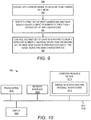
- the computing device 1000 may include a processor 1002, a display 1004, such as a monitor; a network interface 1008, such as a Local Area Network LAN, a wireless 802.11x LAN, a 3G mobile WAN or a WiMax WAN; and a computer-readable medium 1010.
- a bus 1012 may be an EISA, a PCI, a USB, a FireWire, a NuBus, or a PDS.
- the computer readable medium 1010 may be any suitable medium that participates in providing instructions to the processor 1002 for execution.
- the computer readable medium 1010 may be non-volatile media, such as an optical or a magnetic disk; volatile media, such as memory.
- the computer-readable medium 1010 may also store a damage mitigating machine readable instructions 1014, which may perform some or all of the methods 300-900 and may include the modules 210-214 of the damage mitigating apparatus 104 depicted in FIG. 2 .
- the damage mitigating machine readable instructions 1014 may include a data accessing module 210, a damage mitigating module 212, and a drop generator controlling module 214.
Landscapes
- Engineering & Computer Science (AREA)
- Quality & Reliability (AREA)
- Ink Jet (AREA)
Description
- Some commercial products such as printers, graphics plotters, copiers, and facsimile machines may employ thermal ink-jet printing or piezoelectric printhead technology. Thermal ink-jet printing technology typically includes the repeated heating of resistors to fire ink through a plurality of nozzles onto a media. Piezoelectric printhead technology typically includes the repeated actuation of piezoelectric elements to fire ink through a plurality of nozzles onto a media. In some products, the firing elements, e.g., resistors or piezoelectric elements, are arranged in printheads, in which the printheads are smaller in width than the media and are to be scanned across the media. In these types of products, the firing elements are activated at appropriate times as the printheads are scanned one or more times across the media to cause a desired image to be formed on the media. Printing during multiple scans across the media enables printing fluid to be deposited at their desired locations through any of a number of nozzles. In one regard, therefore, in scanning printhead type of products, an operational firing element may be used to deposit ink at a particular location in place of a defective firing element.
- In other products, such as page wide printers, the firing elements are arranged in printheads, in which the printheads are similar to or larger in width than the media. In these types of products, the firing elements are activated at appropriate times to cause printing fluid to be deposited at desired locations on the media during a single pass of either the printheads with respect to the media or the media with respect to the printheads. Typically, the printheads in page wide printers remain fixed while the media moves in a particular direction beneath the printheads.
- Document
US5581284 discloses a method of extending the life of a printbar that comprises an error-hiding algorithm wherein, in case of failure of a nozzle, another nozzle is assigned to eject the drops to the nozzle in failure. - Features of the present disclosure are illustrated by way of example and not limited in the following figure(s), in which like numerals indicate like elements, in which:
-
FIG. 1A is a simplified diagram of a printing system, which may implement various aspects of the methods disclosed herein, according to an example of the present disclosure; -
FIG. 1B is a simplified schematic diagram of a print bar depicted inFIG. 1A , according to an example of the present disclosure; -
FIG. 1C is a simplified schematic diagram of a manner in which signal lines shown inFIG. 1B may be connected between a controller and drop generators, according to an example of the present disclosure; -
FIG. 2 is a simplified block diagram of the printing system shown inFIG. 1A , according to an example of the present disclosure; -
FIGS. 3-9 , respectively, are flow diagrams of methods for mitigating damage to a plurality of drop generators, according to examples of the present disclosure; and -
FIG. 10 is schematic representation of a computing device, which may be employed to perform various functions of the controller depicted inFIG. 2 , according to an example of the present disclosure. - For simplicity and illustrative purposes, the present disclosure is described by referring mainly to an example thereof. In the following description, numerous specific details are set forth in order to provide a thorough understanding of the present disclosure. It will be readily apparent however, that the present disclosure may be practiced without limitation to these specific details. In other instances, some methods and structures have not been described in detail so as not to unnecessarily obscure the present disclosure. As used herein, the terms "a" and "an" are intended to denote at least one of a particular element, the term "includes" means includes but not limited to, the term "including" means including but not limited to, and the term "based on" means based at least in part on.
- Disclosed herein are methods for mitigating damage to a plurality of drop generators in a printing system and apparatuses for implementing the methods. In the methods, data corresponding to an image to be printed on a media by the printing system may be accessed. The data may include data that has been processed for printing, e.g., processed through an imaging pipeline where the data is color mapped, halftoned, linearized, swath cut, etc. In addition, the plurality of drop generators may be controlled to print the image on the media while mitigating damage to the plurality of drop generators and without shifting placement of the image on the media or shifting the plurality of drop generators in a direction perpendicular to a feed direction of the media. Various manners in which damage to the plurality of drop generators may be mitigated are disclosed herein.
- As discussed herein, a drop generator, such as a piezoelectric element or a resistor, may be construed as being damaged if the drop generator has stopped functioning properly. That is, a drop generator may be construed as being damaged if the drop generator is unable to fire a drop of printing fluid through a nozzle or if the drop generator is only able to fire a drop of printing fluid that is relatively smaller than a nominally sized drop, i.e., a drop size corresponding to a properly functioning drop generator. In addition, a drop generator, such as a resistor, may be construed as being damaged if the drop generator has been burned-in. As used herein, "burn-in" of a drop generator may be defined as an uneven wearing of the drop generator as compared with other drop generators in the printing system, as may occur when the drop generator is used a significantly larger number of times as compared to the other drop generators to print portions of images. That is, a drop generator may experience "burn-in" or uneven wearing when that drop generator is activated much more often than neighboring drop generators. One result of burn-in may be that the burnt-in drop generator(s) may be unable to eject a nominal or normal amount of printing fluid. This inability to cause a nominal amount of printing fluid to be ejected may cause the drop generator(s) to drop printing fluid that is sized differently than the printing fluids dropped by its neighboring drop generators. For instance, a burnt-in drop generator may drop a smaller sized drop of printing fluid or a larger sized drop of printing fluid than its neighboring drop generators. In addition, in printing systems in which the same drop generators are responsible for printing along the same line in a feed direction of the media, such as printing systems in which the drop generators are not a lighter or darker band may be printed by the damaged, e.g., burnt-in, drop generators as compared with their neighboring drop generators that are operating nominally. Thus, for instance, the sections of an image printed by the damaged drop generators may appear as a lighter or darker band within the sections of the image printed by neighboring drop generators that have experienced a lesser degree of damage or are less worn.
- By way of example, a set of drop generators may experience damage, e.g., burn-in, if the set of drop generators are employed to print relatively long lines in a feed direction of a media. This may occur in engineering drawings which often include long borders that extend from nearly one edge to an opposite edge of a media.
- Through implementation of the methods and apparatuses disclosed herein, damage to a plurality of drop generators may be mitigated through prevention or delay of the onset of the damage. In addition, or alternatively, the effects of the damage to the drop generators may be mitigated through drop generator control operations that may substantially avoid use of the damaged drop generators, for instance, to print filled in sections of images. Moreover, the mitigation may be provided as an image processing pipeline solution in that the methods and the apparatuses disclosed herein may be implemented without shifting the placement of the image on the media or shifting a position of the drop generators in a direction that is perpendicular to the feed direction of the media. Instead, the mitigation may occur in the image processing pipeline of the printing system.
- With reference first to
FIG. 1A , there is shown a simplified schematic diagram of aprinting system 100, which may implement various aspects of the methods disclosed herein, according to an example. It should be understood that theprinting system 100 depicted inFIG. 1A may include additional elements and that some of the elements depicted therein may be removed and/or modified without departing from a scope of theprinting system 100. - As shown in
FIG. 1A , theprinting system 100 may include acontroller 102 and a number of print bars 106-112, which may equivalently be denoted as die, printheads, etc. Although the print bars 106-112 have been depicted as each including single components, the print bars 106-112 may instead be formed of multiple modules. Each of the print bars 106-112 may be supplied with different colored printing fluids, such as inks, dyes, etc., to be ejected from the print bars 106-112. For instance, afirst print bar 106 may be supplied with a black colored printing fluid, asecond print bar 108 may be supplied with a cyan colored printing fluid, athird print bar 110 may be supplied with a magenta colored printing fluid, and afourth print bar 112 may be supplied with a yellow colored printing fluid. In other examples, theprinting system 100 may include additional print bars that are supplied with differently colored printing fluids and/or each of the print bars 106-112 may be formed of multiple modules. In yet other examples, theprinting system 100 may include asingle print bar 106, for instance, that is to print a black colored printing fluid. - Each of the print bars 106-112 is depicted as including a plurality of
drop generators 114 arranged along two parallel columns. Thedrop generators 114 are depicted as being arranged along a firstdrop generator column 115a and a seconddrop generator column 115b. A relatively small number ofdrop generators 114 are shown for convenience, but it should be clearly understood that each of the print bars 106-112 may include much larger numbers ofdrop generators 114, for instance, to be able to print at 600 dpi or more across the width of amedia 130. Each of thedrop generators 114 may be a resistor (or equivalently, a heating element) or a piezoelectric element that may be individually activated or fired to cause drops of printing fluid to be ejected out of respective nozzles (an example is shown inFIG. 1B ). Thedrop generators 114 may be activated in any manner consistent with known heat generating or piezoelectric actuating drop generators and thus a detailed discussion of a manner in which thedrop generators 114 may be activated to cause printing fluid to be ejected is not provided herein. - As discussed in greater detail herein below, the
controller 102 also includes adamage mitigating apparatus 104 that is to mitigate damage to thedrop generators 114. Particularly, thedamage mitigating apparatus 104 is to mitigate damage to the drop generators in printing an image on themedia 130 while a file containing the image to be printed is in an image processing pipeline of theprinting system 100. In other words, thedamage mitigating apparatus 104 is to mitigate damage to the drop generators in printing the image without moving thedrop generators 114 with respect to themedia 130 in a direction perpendicular to themedia 130feed direction 132 or shifting placement of the image on themedia 130. Various manners in which thedamage mitigating apparatus 104 may mitigate damage to thedrop generators 114 are discussed in detail below. - As also shown in
FIG. 1A , thedrop generators 114 are to drop printing fluid onto themedia 130 as either themedia 130 is fed past the print bars 106-112 in thefeed direction 132 or thedrop generators 114 are moved over the media 140 in a direction opposite thefeed direction 132. In either arrangement, any given location on themedia 130, may receive printing fluid from thesame drop generator 114 and thus, theprinting system 100 may be a fixed printing system. In other words, the print bars 106-112 may not be scanned in a direction perpendicular to thefeed direction 132. However, the print bars 106-112 may be moved slightly, e.g., half a nozzle width, during a printing operation to allow two-pass printing (one pass in each direction) at twice the resolution of single pass printing. In addition, although particular reference is made throughout the present disclosure that themedia 130 is fed in thefeed direction 132, it should be understood that the print bars 106-112 may equivalently be moved in the direction opposite thefeed direction 132 without departing from a scope of the methods and apparatuses disclosed in the present disclosure. - Turning now to
FIG. 1B , there is shown a simplified schematic diagram of aprint bar 106, according to an example. It should be understood that the other print bars 108-112 may have similar configurations as theprint bar 106 depicted inFIG. 1B . It should also be understood that theprint bar 106 depicted inFIG. 1B may include additional elements and/or that the elements depicted therein may be removed and/or modified without departing from a scope of theprint bar 106. - As shown in
FIG. 1B , theprint bar 106 may includemultiple drop generators 114, for instance, arranged along two substantiallyparallel columns drop generators 114 are shown inFIG. 1B ). In addition, thedrop generators 114 may receiveprinting fluid 116 from aprinting fluid supply 118 that may be connected to a printing fluid reservoir (not shown). Particularly, printing fluid 116 from theprinting fluid supply 118 may be supplied into a printing fluid chamber (or equivalently, a firing chamber) 120 and activation of adrop generator 114 may cause aprinting fluid drop 124 to be ejected through anozzle 122 and onto themedia 130. As shown inFIG. 1B , thenozzles 122 on opposite sides of theprinting fluid supply 118 may have approximately the same widths with respect to each other. According to an example, thedrop generator 114 is a resistor that is activated, e.g., heated, through receipt of an electrical signal through asignal line 126. In this example, the heating of thedrop generator 114 may cause a bubble to be formed in theprinting fluid 116 contained in theprinting fluid chamber 120, which may cause aprinting fluid drop 124 to be ejected through thenozzle 122. In another example, thedrop generator 114 is a piezoelectric element that is activated through receipt of an electrical signal through asignal line 126. A simplified example of a manner in which signallines 126 may be connected between thecontroller 102 and thedrop generators 114, according to an example, is depicted inFIG. 1C . It should, however, be understood that thecontroller 102 may control the transmission of electrical signals to each of thedrop generators 114 through use of other mechanisms, for instance, multiplexers, etc. - In any regard, the
controller 102 may selectively activate thedrop generators 114 according to a proper sequence as themedia 130 is fed in thefeed direction 132 to causeprinting fluid 116 to be dropped at the appropriate locations on themedia 130 to form a desired image on themedia 130. The desired image may include any of text, pictures, lines, drawings, filled-in drawings, etc. As discussed in greater detail herein, thecontroller 102, and particularly, thedamage mitigating apparatus 104, may operate thedrop generators 114 in any of a variety of manners to mitigate damage to thedrop generators 114. - Turning now to
FIG. 2 , there is shown a simplified block diagram of theprinting system 100, according to an example. It should be understood that theprinting system 100 depicted inFIG. 2 may include additional elements and that some of the elements depicted therein may be removed and/or modified without departing from a scope of theprinting system 100. - As shown in
FIG. 2 , thecontroller 102 is depicted as including, in addition to thedamage mitigating apparatus 104, aprocessor 202, asignal line interface 204, and a data store 206. Thedamage mitigating apparatus 104 is also depicted as including adata accessing module 210, adamage mitigating module 212, and a dropgenerator controlling module 214. Although not shown, thecontroller 102 may further include an interface to a network connection, for instance, to enable theprocessor 202 to access data corresponding to images to be printed. Thecontroller 102 may still further include an interface to an actuator (not shown) that is to control feeding of themedia 130. - The
processor 202, which may be a microprocessor, a micro-controller, an application specific integrated circuit (ASIC), or the like, is to perform various processing functions in thecontroller 102. The processing functions may include invoking or implementing thedamage mitigating apparatus 104 and particularly, the modules 210-214 of thedamage mitigating apparatus 104, as discussed in greater detail herein below. According to an example, thedamage mitigating apparatus 104 is a hardware device on which is stored various sets of machine readable instructions. Thedamage mitigating apparatus 104 may be, for instance, a volatile or non-volatile memory, such as dynamic random access memory (DRAM), electrically erasable programmable read-only memory (EEPROM), magnetoresistive random access memory (MRAM), memristor, flash memory, floppy disk, a compact disc read only memory (CD-ROM), a digital video disc read only memory (DVD-ROM), or other optical or magnetic media, and the like, on which software may be stored. In this example, the modules 210-214 may be software modules, e.g., sets of machine readable instructions, stored in thedamage mitigating apparatus 104. - In another example, the
damage mitigating apparatus 104 may be a hardware component, such as a chip, and the modules 210-214 may be hardware modules on the hardware component. In a further example, the modules 210-214 may include a combination of software and hardware modules. In a yet further example, theprocessor 202 may be an ASIC that is to perform the functions of the modules 210-214. In this example, theprocessor 202 and thedamage mitigating apparatus 104 may be a single processing apparatus. - The
processor 202 may store data in the data store 206 and may use the data in implementing the modules 210-214. For instance, theprocessor 202 may store data pertaining to an image that is to be printed onto a medium 130. In any regard, the data store 206 may be volatile and/or non-volatile memory, such as DRAM, EEPROM, MRAM, phase change RAM (PCRAM), memristor, flash memory, and the like. In addition, or alternatively, the data store 206 may be a device that may read from and write to a removable media, such as, a floppy disk, a CD-ROM, a DVD-ROM, or other optical or magnetic media. - The
signal line interface 204 may include hardware and/or software to enable theprocessor 202 to respectively send electrical signals to thedrop generators 114 over signal lines 126. Although not shown, thesignal line interface 204 may be connected to a power source from which the electrical signals may be transmitted to therespective drop generators 114. In addition, theprocessor 202 may be connected to an input/output interface (not shown) that may enable theprocessor 202 to access a network, such as an internal network, the Internet, etc., over which theprocessor 202 may receive files containing images to be printed. The input/output interface may include a network interface card and/or may also include hardware and/or software to enable theprocessor 202 to communicate with various input and/or output devices, such as a keyboard, a mouse, a display, another computing device, etc., through which a user may input instructions into theprinting system 100. - Various manners in which the
processor 202 in general, and the modules 210-214 in particular, may be implemented are discussed in greater detail with respect to the methods 300-900 respectively depicted inFIGS. 3-9 . Particularly,FIGS. 3-9 , respectively, depict flow diagrams of methods 300-900 for mitigating damage to a plurality ofdrop generators 114 in aprinting system 100, according to various examples. It should be apparent to those of ordinary skill in the art that the methods 300-900 may represent generalized illustrations and that other operations may be added or existing operations may be removed, modified, or rearranged without departing from the scopes of the methods 300-900. Generally speaking, theprocessor 202 depicted inFIG. 2 may implement any of methods 300-900 through implementation of at least some of the modules 210-214. In addition, each of the methods 400-900 generally includes features that are more specific examples of the features contained in themethod 300. - The descriptions of the methods 300-900 are made with reference to the
printing system 100 illustrated inFIGS. 1A-2 for purposes of illustration. It should, however, be clearly understood that printing systems having other configurations may be implemented to perform any of the methods 300-900 without departing from the scopes of the methods 300-900. - With reference first to the
method 300 depicted inFIG. 3 , atblock 302, data corresponding to an image to be printed on amedia 130 may be accessed. For instance, data representing the image that has been processed for printing by the printing system to be printed may be stored in the data store 206. In this example, thedata accessing module 210 may access the data from the data store 206. In other examples, thedata accessing module 210 may access the data from other sources, for instance, from an external data store over a local area network, over a wide area network, from an externally attached storage device, etc. - At
block 304, thedrop generators 114 may be controlled to print the image on the media while mitigating damage to the plurality ofdrop generators 114 and without shifting placement of the printed image on themedia 130 or shifting the plurality of drop generators in a direction perpendicular to a feed direction of themedia 130. For instance, thedamage mitigating module 212 may determine how thedrop generators 114 are to be operated to mitigate damage to thedrop generators 114. In other words, thedamage mitigating module 212 may determine which of thedrop generators 114 are to be activated at which times for an image printing operation to cause thedrop generators 114 to wear substantially evenly with respect to each other, without shifting placement of the printed image on themedia 130 or shifting thedrop generators 114 in a direction that is perpendicular to the feed ofdirection 132 of themedia 130. That is, thedamage mitigating module 212 may determine the timing at which selecteddrop generators 114 or groups ofdrop generators 114 are to be activated to print the image on themedia 130 such that the margins between the edges of themedia 130 and the printed image are sized as originally intended. In other words, therefore, the drop generator control while mitigating damage atblock 304 may be achieved without printing the image with an entirely shifted set ofdrop generators 114. - In addition, in accordance with the determination as to how the
drop generators 114 are to be operated, the dropgenerator controlling module 214 may control thedrop generators 114 individually or in respective groups to drop printing fluid onto themedia 130 at appropriate times while themedia 130 is fed past thedrop generators 114 to thus cause the image to be printed onto themedia 130. Various examples in which thedamage mitigating module 212 may make this determination and the dropgenerator controlling module 214 may control thedrop generators 114 according to the determination are discussed in greater detail below with respect to the methods 400-900. - According to an example, the
damage mitigating module 212 may determine that certain ones of thedrop generators 114 are to be activated instead of other ones of thedrop generators 114 in printing the image to thus cause thedrop generators 114 to wear substantially evenly with respect to each other. In addition, thedamage mitigating module 212 may make this determination such that thedrop generators 114 wear substantially evenly with respect to each other over the course of printing a relatively large number of images, e.g., over more than 100 images. Thus, for instance, although a set of thedrop generators 114 may be activated a substantially larger number of times than another set of thedrop generators 114 to print a particular image, thedamage mitigating apparatus 104 may implement a drop generator utilization technique, as disclosed herein, that substantially prevents a group of thedrop generators 114 from being activated much more often than other groups of thedrop generators 114 to thereby mitigate damage to thedrop generators 114. - According to an example, an initial determination of which of the
drop generators 114 are to be activated at which times to print the image may be made prior to the determination by thedamage mitigating module 212. The initial determination may therefore be the order and timing (e.g., sequence) at which thedrop generators 114 are to be activated under a nominal printing operation. In other words, the initial determination may identify a printing operation that would be performed if the damage mitigating operation disclosed herein were not implemented. As such, in one regard, the control of the drop generators atblock 304 represents use of sets ofdrop generators 114 that differs from their use in a nominal printing operation. - In addition, because the
printing system 100 may be a fixed printing system and thus, the print bars 106-112 on which thedrop generators 114 are positioned may not move in a direction perpendicular to thefeed direction 132 during a printing operation, control of thedrop generators 114 to mitigate damage atblock 304 may be achieved without moving either the print bars 106-112 or themedia 130 in a direction perpendicular to thefeed direction 132, and thus thedrop generators 114, with respect to themedia 130. Moreover, block 304 may be applied to thedrop generators 114 in a single one of the print bars 106 or may be applied to thedrop generators 114 respectively in multiple ones of the print bars 106-112. - With reference now to the
method 400 depicted inFIG. 4 , atblock 402, data corresponding to an image to be printed on amedia 130 may be accessed. The data may be accessed in any of the manners discussed above with respect to block 302 in themethod 300 depicted inFIG. 3 . - At
block 404, a characteristic type of the image to be printed may be determined. For instance, thedata accessing module 210 may determine a characteristic type of the image to be printed, in which the characteristic type may be, for instance, whether the image includes a section that is intended to be printed primarily by a particular set ofdrop generators 114 in a highly repetitive manner, e.g., a relatively long straight line, whether the image is intended to be printed by a relatively large set ofdrop generators 114 without causing any subset of thedrop generators 114 to be activated substantially more often than any other subset of thedrop generators 114, e.g., a filled in or solid section, etc. By way of particular example, a characteristic type of the image to be printed may be that the image is an engineering drawing, which may include relatively long lines that extend near the edges of themedia 130 to form borders around drawings contained within the borders and thus may require highly repetitive use of a set ofdrop generators 114 with respect toother drop generators 114. As another example, a characteristic type of the image to be printed may be that the image contains relatively large solid sections. - According to an example, and as shown in
FIG. 4 , atblock 404, a determination may be made as to whether the image to be printed has either a first characteristic type (A) or a second characteristic type (B). As discussed in the example above, a first characteristic type may be that the image to be printed is an engineering drawing, e.g., a computer aided drawing, and a second characteristic type may be that the image to be printed is an image that contains relatively large solid sections. - As indicated at block 406, in response to a determination being made at
block 404 that the image to be printed has a first characteristic type, control of thedrop generators 114 may include controlling thedrop generators 114 to print the image exclusively with a first subset of thedrop generators 114. Alternatively, as indicated atblock 408, in response to a determination being made atblock 404 that the image to be printed has a second characteristic type, control of thedrop generators 114 may include controlling thedrop generators 114 to print the image exclusively with a second subset of thedrop generators 114. The first subset ofdrop generators 114 may be non-overlapping with the second subset of the plurality ofdrop generators 114. In addition, blocks 406 and 408 may be applied to thedrop generators 114 in a single one of the print bars 106 or may be applied to thedrop generators 114 respectively in multiple ones of the print bars 106-112. - According to an example, the first subset of
drop generators 114 are thedrop generators 114 located along onecolumn 115a of aprint bar 106 and the second subset ofdrop generators 114 are thedrop generators 114 located along theother column 115b of theprint bar 106, for instance, as shown inFIG. 1A . By way of particular example, all of the lines of an engineering drawing, which typically do not include large sections of filled areas, may be printed with thedrop generators 114 located along afirst column 115a of aprint bar 106. In this example, all of the features of an image containing sections of filled areas may be printed with thedrop generators 114 located along asecond column 115b of theprint bar 106. As some of thedrop generators 114 located in thefirst column 115a of theprint bar 106, for instance, may be used to print a large number of borders in engineering drawings, thosedrop generators 114 may be more likely to be damaged at a faster rate as compared withother drop generators 114. However, because thosedrop generators 114 may be limited to printing engineering drawings and thus may not likely print filled areas, the effects of damage, e.g., burn-in, on thosedrop generators 114 may not be readily visible. In addition, because thedrop generators 114 located in thesecond column 115b may not be used to print the borders of engineering drawings, thosedrop generators 114 may be less likely to experience damage. As such, thedrop generators 114 located in thesecond column 115b may be used to print filled areas without causing detrimental effects, e.g., banding, in those filled areas of the image caused by damage to, e.g., burn-in of, thedrop generators 114 located in thefirst column 115a. - According to an example, a
bad drop generator 114 located along thefirst column 115a of aprint bar 106 may be replaced with adrop generator 114 located across from thebad drop generator 114 in thesecond column 115b of theprint bar 106 during printing operations. A bad drop generator may be a drop generator that has failed or is otherwise operating improperly. - Although the
method 400 is described with respect to two characteristic types, it should be understood that themethod 400 may be implemented through consideration of any reasonably suitable number of characteristic types. That is, atblock 404, for instance, a determination may be made as to whether the image to be printed is of any number of different characteristic types. In addition, blocks 406 and 408 may be implemented responsive to the image to be printed being any of the number of different characteristic types. Alternatively, themethod 400 may includedrop generator 114 control options in addition toblocks 406 and 408 depending upon the characteristic type of the image to be printed. The additional control options may include, for instance, control of other subsets of thedrop generators 114. - In other examples in which the image to be printed does not contain any of the characteristic types considered at
block 404, thedrop generators 114 may be controlled to be activated in a manner other than through implementation ofblocks 406 or 408. In other words, thedrop generators 114 may be operated in a default manner in which thedrop generators 114 are operated according to a nominal printing operation to print the image. - Turning now to the
method 500 depicted inFIG. 5 , atblock 502, data corresponding to an image to be printed on amedia 130 may be accessed. The data may be accessed in any of the manners discussed above with respect to block 302 in themethod 300 depicted inFIG. 3 . - At
block 504, a first characteristic type of a first section and a second characteristic type of a second section of the image to printed may be determined. For instance, the image to be printed may include multiple sections in which at least two of the sections include different characteristic types from each other. In addition, thedata accessing module 210 may determine the different characteristic types of the sections of the image to be printed. The characteristic types may include any of the characteristic types discussed above with respect to themethod 400. - At
block 506, a first subset of thedrop generators 114 may be controlled to exclusively print the first section of the image and a second subset of thedrop generators 114 may be controlled to exclusively print the second section of the image. Particularly, for instance, the dropgenerator controlling module 214 may control thedrop generators 114 in this manner. The first subset ofdrop generators 114 may be thosedrop generators 114 located along afirst column 115a of aprint bar 106 and the second subset ofdrop generators 114 may be thosedrop generators 114 located along asecond column 115b of theprint bar 106. In addition, the first subset ofdrop generators 114 may include a non-overlapping set ofdrop generators 114 as compared with the second subset of the plurality ofdrop generators 114. Moreover, block 506 may be applied to thedrop generators 114 in a single one of the print bars 106 or may be applied to thedrop generators 114 respectively in multiple ones of the print bars 106-112. - By way of particular example, the first characteristic type is a line drawing section, e.g., an engineering drawing, and the second characteristic type is a filled area section of the image. In this example, printing of the image using the first subset of the
drop generators 114 to exclusively print the first section and using the second subset of the drop generators to exclusively print the second section may mitigate effects of drop generator damage, such as burn-in, for at least the reasons discussed above with respect to themethod 400. - Turning now to the
method 600 depicted inFIG. 6 , atblock 602, data corresponding to an image to be printed on amedia 130 may be accessed. The data may be accessed in any of the manners discussed above with respect to block 302 in themethod 300 depicted inFIG. 3 . - At
block 604, a first characteristic type of a first section and a second characteristic type of a second section of the image to printed may be determined. For instance, the image to be printed may include multiple sections in which at least two of the sections include different characteristic types from each other. In addition, thedata accessing module 210 may determine the different characteristic types of the sections of the image to be printed. The characteristic types may include any of the characteristic types discussed above with respect to themethod 400. - At
block 606, a first subset of thedrop generators 114 may be controlled to exclusively print both the first section of the image and the second section of the image. Particularly, for instance, the dropgenerator controlling module 214 may control thedrop generators 114 in this manner. The first subset ofdrop generators 114 may be thosedrop generators 114 located along afirst column 115a of aprint bar 106 and the second subset ofdrop generators 114 may be thosedrop generators 114 located along asecond column 115b of theprint bar 106. In addition, the first subset ofdrop generators 114 may include a non-overlapping set ofdrop generators 114 as compared with the second subset of the plurality ofdrop generators 114. Moreover, block 606 may be applied to thedrop generators 114 in a single one of the print bars 106 or may be applied to thedrop generators 114 respectively in multiple ones of the print bars 106-112. - By way of particular example, the first characteristic type is a line drawing section, e.g., an engineering drawing, and the second characteristic type is a filled area section of the image. In this example, printing of the image using the first subset of the
drop generators 114 to exclusively print the first section and the second section may mitigate effects of drop generator damage, such as burn-in, for at least the reasons discussed above with respect to themethod 400. - With reference now to the
method 700 inFIG. 7 , atblock 702, data corresponding to an image to be printed on amedia 130 may be accessed. The data may be accessed in any of the manners discussed above with respect to block 302 in themethod 300 depicted inFIG. 3 . - At
block 704, a determination may be made that a section of the image is to be printed in a black color. The section of the image may include a portion of the image or the entire image. In addition, for instance, thedata accessing module 210 may make this determination based upon an analysis of the data corresponding to the image. This determination may also include a determination of the location in the image of the section of the image that is to be printed in the black color. - At
block 706, thedrop generators 114 appropriately located in each of thefirst print bar 106, thesecond print bar 108, thethird print bar 110, and thefourth print bar 112 may be controlled to print the determined section. That is, instead of exclusively activating thedrop generators 114 in theprint bar 106 that is supplied with black colored printing fluid to be deposited, thedrop generators 114 in the print bars 108-112 that are supplied with other colored printing fluids, e.g., yellow, cyan, and magenta, may be activated with theprint bar 106 to print the determined section to have the black color. That is, the appropriately locateddrop generators 114, for instance, thedrop generators 114 located along a common line extending in the direction in which themedia 130 is fed, may each drop printing fluid such that the combination of the printing fluids along common locations on themedia 130 may have a black color. - With reference now to the
method 800 inFIG. 8 , atblock 802, data corresponding to an image to be printed on amedia 130 may be accessed. The data may be accessed in any of the manners discussed above with respect to block 302 in themethod 300 depicted inFIG. 3 . - At
block 804, a determination may be made of a tone of a section of the image. The section of the image may include a portion of the image or the entire image. In addition, for instance, thedata accessing module 210 may make this determination based upon an analysis of the data corresponding to the image. This determination may also include a determination of the location in the image of the section of the image having the determined tone. - At
block 806, appropriately locateddrop generators 114 in each of thesecond print bar 108, thethird print bar 110, and thefourth print bar 112 may be controlled to print the determined section in response to the section being determined to be a midtone. A midtone may be defined as a tone between and not including approximately complete black and approximately complete white. In addition, as discussed above, thefirst print bar 106 may be supplied with a black colored printing fluid, thesecond print bar 108 may be supplied with a cyan colored printing fluid, thethird print bar 110 may be supplied with a magenta colored printing fluid, and thefourth print bar 112 may be supplied with a yellow colored printing fluid. As noted atblock 806, the appropriately locateddrop generators 114 in each of the print bars 108-112 other than thefirst print bar 106 may be implemented to print the section of the image containing a midtone. In other words, the section, when it contains a midtone, may be printed using printing fluids having colors other than black. In one regard, therefore, thedrop generators 114 in thefirst print bar 106, which may be supplied with black colored printing fluid, may be exclusively used to print nearly complete black colors and nearly complete white colors. An example of the utilization of the different colored printing fluids for different tones is provided below in Table 1.Table 1 Tone Black (K) % Cyan (C) % Magenta (M) % Yellow (Y) % White 5 2 2 2 Nearly White 3 8 8 8 Midtone 0 8 8 8 Midtone 0 15 15 15 Midtone 0 30 30 30 Nearly Black 0 40 40 40 Black 10 40 40 40 - As shown in Table 1, the tone may increase from white to black and depending upon the tone, various amounts of the different colored printing fluids may be used in printing that tone of the color black.
- With reference now to the
method 900 inFIG. 9 , atblock 902, data corresponding to an image to be printed on amedia 130 may be accessed. The data may be accessed in any of the manners discussed above with respect to block 302 in themethod 300 depicted inFIG. 3 . - At
block 904, an identification may be made of a first set of drop generators that have been activated a greater number of times than a second set of drop generators in asingle print bar 106. For instance, thedamage mitigating module 212 may make this identification based upon a profiling of thedrop generators 114 in theprint bar 106. Particularly, thedamage mitigating module 212 may count the number of times each of thedrop generators 114 in theprint bar 106 have been fired and may determine which of thedrop generators 114 are likely to have a higher likelihood of damage, e.g., burn-in, as well as the severity of the damage based upon the count. Thus, for instance, thedamage mitigating module 212 may identify the potentially damaged, e.g., burnt-in, dropgenerators 114 as thosedrop generators 114 that have been activated more than a predetermined number of times. As another example, thedamage mitigating module 212 may identify the potentially damaged, e.g., burnt-in, dropgenerators 114 as thosedrop generators 114 that have been activated more than a predetermined number of times over the number of times thatother drop generators 114 have been activated. - In addition, the
damage mitigating module 212 may determine a correction factor for the potentially damageddrop generators 114. The correction factor may be an increase in the number of times that the potentially damageddrop generators 114 are to be activated in comparison toother drop generators 114 for a given printing operation. - At
block 906, the first set of drop generators, which may be the drop generators that are potentially damaged, e.g., burnt-in, may be controlled to drop a different number of printing fluid drops than the second set of drop generators, which may be the drop generators that are not or are potentially less damaged, in printing features of the image having the same characteristics. That is, for instance, the dropgenerator controlling module 214 may activate the first set of drop generators a different number of times than the second set of drop generators to print the same color (e.g., RGB) value. By way of particular example, the dropgenerator controlling module 214 may create an RGB value of 128, 128, 128 by using 1 black colored drop per 600 dpi pixel with the second set of drop generators but may use 1.1 black colored drops per 600 dpi pixel with the first set of drop generators. As another example, the dropgenerator controlling module 214 may create an RGB value of 128, 128, 128 by using 1 black colored drop per 600 dpi pixel with the second set of drop generators but may use 0.9 black colored drops per 600 dpi pixel with the first set of drop generators. In one regard, therefore, themethod 900 may substantially equalize the amount of printing fluid deposited fromdrop generators 114 that are damaged and those that are operating normally, thus mitigating the effects of the damage. - The first set of drop generators may not overlap with the second set of the drop generators. In addition, block 906 may be applied to the
drop generators 114 in a single one of the print bars 106 or may be applied to thedrop generators 114 respectively in multiple ones of the print bars 106-112. - According to a further example, a user may be notified that a set of drop generators may or may likely become damaged and may also be provided with instructions to manually delay and/or mitigate the damage. For instance, the
damage mitigating apparatus 104 may output, e.g., display, a message for the user that repeated pattern printing will likely result in print bar degradation and that the user should thus rotate some of the print bars or modules of the print bars. - Some or all of the operations set forth in the methods 300-900 may be contained as utilities, programs, or subprograms, in any desired computer accessible medium. In addition, the methods 300-900 may be embodied by computer programs, which may exist in a variety of forms both active and inactive. For example, they may exist as machine readable instructions, including source code, object code, executable code or other formats. Any of the above may be embodied on a non-transitory computer readable storage medium.
- Examples of non-transitory computer readable storage media include computer system RAM, ROM, EPROM, EEPROM, and magnetic or optical disks or tapes. It is therefore to be understood that any electronic device capable of executing the above-described functions may perform those functions enumerated above.
- Turning now to
FIG. 10 , there is shown a schematic representation of acomputing device 1000, which may be employed to perform various functions of thecontroller 102 depicted inFIG. 2 , according to an example. Thecomputing device 1000 may include aprocessor 1002, adisplay 1004, such as a monitor; anetwork interface 1008, such as a Local Area Network LAN, a wireless 802.11x LAN, a 3G mobile WAN or a WiMax WAN; and a computer-readable medium 1010. Each of these components may be operatively coupled to abus 1012. For example, thebus 1012 may be an EISA, a PCI, a USB, a FireWire, a NuBus, or a PDS. - The computer readable medium 1010 may be any suitable medium that participates in providing instructions to the
processor 1002 for execution. For example, the computer readable medium 1010 may be non-volatile media, such as an optical or a magnetic disk; volatile media, such as memory. The computer-readable medium 1010 may also store a damage mitigating machinereadable instructions 1014, which may perform some or all of the methods 300-900 and may include the modules 210-214 of thedamage mitigating apparatus 104 depicted inFIG. 2 . In this regard, the damage mitigating machinereadable instructions 1014 may include adata accessing module 210, adamage mitigating module 212, and a dropgenerator controlling module 214. - Although described specifically throughout the entirety of the instant disclosure, representative examples of the present disclosure have utility over a wide range of applications, and the above discussion is not intended and should not be construed to be limiting, but is offered as an illustrative discussion of aspects of the disclosure.
Claims (13)
- A method for mitigating damage to a plurality of drop generators (114) in a printing system (100), said method comprising:accessing data corresponding to an image to be printed on a media (130) by the printing system (100); anddetermining a characteristic type of the image to be printed;controlling the plurality of drop generators (114) to print the image on the media (130) while mitigating damage to the plurality of drop generators (114) and without shifting placement of the image on the media (130) or shifting the plurality of drop generators (114) in a direction perpendicular to a feed direction (132) of the media (130).wherein controlling the plurality of drop generators (114) while mitigating damage to the plurality of drop generators (114) further comprises controlling the plurality of drop generators (114) to print the image exclusively with a first subset of the plurality of drop generators (114) in response to the image to be printed having a first characteristic type and printing the image exclusively with a second subset of the plurality of drop generators (114) in response to the image to be printed having a second characteristic type.
- The method according to claim 1, wherein the second subset of the plurality of drop generators (114) includes a non-overlapping set of drop generators as compared with the first subset of the plurality of drop generators (114).
- The method according to claim 1, wherein the plurality of drop generators (114) are arranged along two columns along a print bar, said method further comprising:determining a characteristic type of the image to be printed; andwherein controlling the plurality of drop generators (114) while mitigating damage to the plurality of drop generators further comprises controlling the plurality of drop generators (114) to print the image exclusively with the plurality of drop generators arranged along one of the two columns in response to the image having a first characteristic type and to print the image exclusively with the plurality of drop generators of the other of the two columns in response to the image having a second characteristic type.
- The method according to claim 1, wherein the image to be printed includes a first section and a second section, said method further comprising:determining a first characteristic type of the first section and a second characteristic type of the second section, wherein the first characteristic type differs from the second characteristic type; andwherein controlling the plurality of drop generators (114) while mitigating damage to the plurality of drop generators further comprises controlling the plurality of drop generators (114) to print the first section exclusively with a first subset of the plurality of drop generators (114) and the second section exclusively with a second subset of the plurality of drop generators (114).
- The method according to claim 1, wherein the image to be printed includes a first section and a second section, said method further comprising:determining a first characteristic type of the first section and a second characteristic type of the second section, wherein the first characteristic type differs from the second characteristic type; andwherein controlling the plurality of drop generators (114) while mitigating damage to the plurality of drop generators (114) further comprises controlling the plurality of drop generators (114) to print the first section and the second section exclusively with a first subset of the plurality of drop generators (114).
- The method according to claim 1, wherein a first set of the plurality of drop generators (114) is arranged on a first print bar (106) to print a first color, a second set of the plurality of drop generators (114) is arranged on a second print bar (108) to print a second color, a third set of the plurality of drop generators (114) is arranged on a third print bar (110) to print a third color, and a fourth set of the plurality of drop generators (114) is arranged on a fourth print bar (112) to print a black color, said method further comprising:determining that a section of the image is to be printed in a black color; andwherein controlling the plurality of drop generators (114) while mitigating damage to the plurality of drop generators further comprises controlling the plurality of drop generators (114) to print the section using appropriately located drop generators (114) in each of the first print bar (106), the second print bar (108), the third print bar (110), and the fourth print bar (112).
- The method according to claim 1, wherein a first set of the plurality of drop generators (114) is arranged on a first print bar (106) to print a black colored printing fluid, a second set of the plurality of drop generators (114) is arranged on a second print bar (108) to print a second colored printing fluid, a third set of the plurality of drop generators (114) is arranged on a third print bar (110) to print a third colored printing fluid, and a fourth set of the plurality of drop generators (114) is arranged on a fourth print bar (112) to print a fourth colored printing fluid, said method further comprising:determining a tone of a section of the image to be printed; andwherein controlling the plurality of drop generators (114) while mitigating damage to the plurality of drop generators further comprises controlling the plurality of drop generators to print the section exclusively using appropriately located drop generators in each of the second print bar (108), the third print bar (110), and the fourth print bar (112) in response to the section being determined to be a midtone.
- The method according to claim 1, wherein the plurality of drop generators (114) are arranged on a single print bar, said method further comprising:identifying a first set of the plurality of drop generators (114) that have been activated a greater number of times than a second set of the plurality of drop generators (114); andmitigating effects of damage to the plurality of drop generators (114) by controlling the first set of the plurality of drop generators to drop a different number of printing fluid drops than the second set of the plurality of drop generators (114) in printing features of the image having the same characteristics.
- An apparatus for mitigating damage to a plurality of drop generators (114) in a printing system (100), said apparatus comprising:a data accessing module (210) to access data corresponding to an image to be printed on the media by the printing system (100) and to determine a characteristic type of at least a section of the image to be printed;a drop generator controlling module (214) to control the plurality of drop generators (114) to print the image on the media while mitigating damage to the plurality of drop generators (114) through control of the plurality of drop generators (114) to print at least the section of the image exclusively with either a first subset of the plurality of drop generators and a second subset of the plurality of drop generators depending upon the determined characteristic type of at least the section of the image to be printed; anda processor (202) to implement the data accessing module (210) and the drop generator controlling module (214).
- The apparatus according to claim 9, wherein the drop generator controlling module (214) is to control the plurality of drop generators (114) to print the image exclusively with the first subset of the plurality of drop generators (114) in response to the at least the section of the image being determined to have a first characteristic type and to control the plurality of drop generators to print the image exclusively with the second subset of the plurality of drop generators (114) in response to the at least the section of the image being determined to have a second characteristic type.
- The apparatus according to claim 9, wherein the plurality of drop generators (114) are arranged along two columns along a print bar (106, 108, 110, 112) and wherein the first subset of the plurality of drop generators (114) are the plurality of drop generators (114) arranged along one of the two columns and the second subset of the plurality of drop generators (114) are the plurality of drop generators (114) arranged along the other of the two columns.
- The apparatus according to claim 9, wherein the data accessing module (210) is further to determine that a first section of the image has a first characteristic type and that a second section of the image has second characteristic type, and wherein the drop generator controlling module (214) is to control the plurality of drop generators (114) to print the first section exclusively with the first subset of the plurality of drop generators (114) and the second section exclusively with the second subset of the plurality of drop generators (114).
- A non-transitory computer readable storage medium on which is stored machine readable instructions that when executed by a processor (202) cause the processor (202) to:access data corresponding to an image to be printed on a media by a printing system having an array of drop generators (114);determine a characteristic type of the image to be printed;control the array of drop generators (114) to print the image on the media while mitigating damage to the array of drop generators (114), without shifting placement of the image on the media or shifting the array of drop generators in a direction perpendicular to a feed direction (132) of the media; andcontrol the array of drop generators (114) to print the image exclusively with a first subset of the plurality of drop generators (114) in response to the image to be printed having a first characteristic type and printing the image exclusively with a second subset of the plurality of drop generators (114) in response to the image to be printed having a second characteristic type.
Applications Claiming Priority (1)
| Application Number | Priority Date | Filing Date | Title |
|---|---|---|---|
| PCT/US2014/035289 WO2015163884A1 (en) | 2014-04-24 | 2014-04-24 | Mitigating damage to drop generators in a printing system |
Publications (3)
| Publication Number | Publication Date |
|---|---|
| EP3134270A1 EP3134270A1 (en) | 2017-03-01 |
| EP3134270A4 EP3134270A4 (en) | 2017-12-27 |
| EP3134270B1 true EP3134270B1 (en) | 2019-01-02 |
Family
ID=54332915
Family Applications (1)
| Application Number | Title | Priority Date | Filing Date |
|---|---|---|---|
| EP14890282.8A Active EP3134270B1 (en) | 2014-04-24 | 2014-04-24 | Mitigating damage to drop generators in a printing system |
Country Status (5)
| Country | Link |
|---|---|
| US (1) | US10377130B2 (en) |
| EP (1) | EP3134270B1 (en) |
| CN (1) | CN106457857B (en) |
| BR (1) | BR112016022041B1 (en) |
| WO (1) | WO2015163884A1 (en) |
Families Citing this family (1)
| Publication number | Priority date | Publication date | Assignee | Title |
|---|---|---|---|---|
| US10596827B2 (en) | 2018-04-06 | 2020-03-24 | Datamax-O'neil Corporation | Methods and systems for operating a printer apparatus |
Family Cites Families (18)
| Publication number | Priority date | Publication date | Assignee | Title |
|---|---|---|---|---|
| US5581284A (en) | 1994-11-25 | 1996-12-03 | Xerox Corporation | Method of extending the life of a printbar of a color ink jet printer |
| US6354687B1 (en) | 1999-11-24 | 2002-03-12 | Hewlett Packard Company | Ink-jet printing and servicing by predicting and adjusting ink-jet component performance |
| JP2003170577A (en) | 2001-12-05 | 2003-06-17 | Sony Corp | Image forming apparatus and image forming method |
| ES2429870T3 (en) * | 2002-09-11 | 2013-11-18 | Nestec Ltd. | Food product for pets, and procedure to produce it |
| US20060087531A1 (en) | 2004-10-25 | 2006-04-27 | Eiseman Michael J | Inkjet printing apparatus |
| KR100636325B1 (en) | 2004-12-14 | 2006-10-18 | 삼성전자주식회사 | Missing nozzle compensation method of printer and printer using same |
| JP2006187872A (en) * | 2004-12-28 | 2006-07-20 | Canon Inc | Inkjet recording apparatus and inkjet recording method |
| US7533965B2 (en) | 2005-03-07 | 2009-05-19 | Eastman Kodak Company | Apparatus and method for electrostatically charging fluid drops |
| KR100788664B1 (en) | 2005-05-26 | 2007-12-26 | 삼성전자주식회사 | Printhead and scanning-type inkjet image forming apparatus having the same, and high resolution implementation method |
| US20060274111A1 (en) | 2005-06-01 | 2006-12-07 | Cho Seo-Hyun | Printhead and inkjet image forming apparatus having the same |
| US7474321B2 (en) | 2005-08-03 | 2009-01-06 | Carestream Health, Inc. | Thermal recording method and system employing edge printing |
| JP2007130974A (en) | 2005-11-14 | 2007-05-31 | Fuji Xerox Co Ltd | Recording apparatus and recording method |
| JP2010000680A (en) | 2008-06-20 | 2010-01-07 | Canon Finetech Inc | Recording system |
| JP5365393B2 (en) * | 2008-11-28 | 2013-12-11 | セイコーエプソン株式会社 | Printing apparatus, printing method, and program |
| JP5587055B2 (en) * | 2010-06-24 | 2014-09-10 | キヤノン株式会社 | Image processing apparatus and image processing method |
| JP2012040808A (en) * | 2010-08-20 | 2012-03-01 | Canon Inc | Printing apparatus and printing method |
| JP5886077B2 (en) | 2012-02-27 | 2016-03-16 | 富士フイルム株式会社 | Inkjet recording apparatus and method and method for manufacturing sanitary products |
| JP2013225172A (en) | 2012-04-19 | 2013-10-31 | Canon Finetech Inc | Information processing device, recording system, processing method therefor, and program |
-
2014
- 2014-04-24 US US15/303,952 patent/US10377130B2/en active Active
- 2014-04-24 EP EP14890282.8A patent/EP3134270B1/en active Active
- 2014-04-24 WO PCT/US2014/035289 patent/WO2015163884A1/en not_active Ceased
- 2014-04-24 CN CN201480078241.6A patent/CN106457857B/en active Active
- 2014-04-24 BR BR112016022041-2A patent/BR112016022041B1/en active IP Right Grant
Non-Patent Citations (1)
| Title |
|---|
| None * |
Also Published As
| Publication number | Publication date |
|---|---|
| BR112016022041B1 (en) | 2021-12-21 |
| WO2015163884A1 (en) | 2015-10-29 |
| US10377130B2 (en) | 2019-08-13 |
| EP3134270A4 (en) | 2017-12-27 |
| CN106457857B (en) | 2019-12-17 |
| BR112016022041A2 (en) | 2017-10-10 |
| CN106457857A (en) | 2017-02-22 |
| US20170036441A1 (en) | 2017-02-09 |
| EP3134270A1 (en) | 2017-03-01 |
Similar Documents
| Publication | Publication Date | Title |
|---|---|---|
| US9757941B2 (en) | Image content based spit bars | |
| JP2010083007A (en) | Apparatus, method and program for processing image, and image recording apparatus | |
| US20170203562A1 (en) | Warming printheads during print passes | |
| US9138989B2 (en) | Printing control apparatus and printing control method for distributing quantized image data | |
| US20150296095A1 (en) | Image processing apparatus, image processing method, recording apparatus, and non-transitory computer-readable storage medium | |
| JP2007237563A (en) | Image forming apparatus and image forming method | |
| US8789907B2 (en) | Processing printhead control data and printing system | |
| US9895915B2 (en) | Compensating swath height error | |
| US10112386B2 (en) | Non-uniform spitting | |
| US10377130B2 (en) | Mitigating damage to drop generators in a printing system | |
| US10654286B2 (en) | Configurable error hiding | |
| JP2011046003A (en) | Two-dimensional code generation system, two-dimensional code generation program and inkjet recorder | |
| US7517042B2 (en) | Delaying printing in response to highest expected temperature exceeding a threshold | |
| JP2009274233A (en) | Liquid ejecting apparatus | |
| US10384444B2 (en) | Recording apparatus and recording method | |
| US7300128B2 (en) | Distributing print density | |
| US20060203021A1 (en) | Printing using a subset of printheads | |
| JP6045206B2 (en) | Inkjet recording method and inkjet recording apparatus | |
| JP2009274234A (en) | Method of calculating correction value, and method of ejecting liquid | |
| US20180141332A1 (en) | Enhancing temperature distribution uniformity across a printer die | |
| EP1593516B1 (en) | Printing method with camouflage of defective print elements | |
| JP6992022B2 (en) | Recording device, recording method and recording system | |
| JP5617002B2 (en) | Fault-tolerant inkjet printer using adjacent nozzles | |
| EP3738777B1 (en) | Thermal printer and printing method | |
| WO2017039601A1 (en) | Media expansion compensated print content |
Legal Events
| Date | Code | Title | Description |
|---|---|---|---|
| PUAI | Public reference made under article 153(3) epc to a published international application that has entered the european phase |
Free format text: ORIGINAL CODE: 0009012 |
|
| STAA | Information on the status of an ep patent application or granted ep patent |
Free format text: STATUS: REQUEST FOR EXAMINATION WAS MADE |
|
| 17P | Request for examination filed |
Effective date: 20160902 |
|
| AK | Designated contracting states |
Kind code of ref document: A1 Designated state(s): AL AT BE BG CH CY CZ DE DK EE ES FI FR GB GR HR HU IE IS IT LI LT LU LV MC MK MT NL NO PL PT RO RS SE SI SK SM TR |
|
| AX | Request for extension of the european patent |
Extension state: BA ME |
|
| DAX | Request for extension of the european patent (deleted) | ||
| A4 | Supplementary search report drawn up and despatched |
Effective date: 20171128 |
|
| RIC1 | Information provided on ipc code assigned before grant |
Ipc: B41J 2/045 20060101AFI20171122BHEP Ipc: B41J 29/393 20060101ALI20171122BHEP Ipc: B41J 2/165 20060101ALI20171122BHEP Ipc: B41J 2/21 20060101ALI20171122BHEP Ipc: B41J 29/38 20060101ALI20171122BHEP |
|
| REG | Reference to a national code |
Ref country code: DE Ref legal event code: R079 Ref document number: 602014039391 Country of ref document: DE Free format text: PREVIOUS MAIN CLASS: B41J0029393000 Ipc: B41J0002045000 |
|
| GRAP | Despatch of communication of intention to grant a patent |
Free format text: ORIGINAL CODE: EPIDOSNIGR1 |
|
| STAA | Information on the status of an ep patent application or granted ep patent |
Free format text: STATUS: GRANT OF PATENT IS INTENDED |
|
| RIC1 | Information provided on ipc code assigned before grant |
Ipc: B41J 2/045 20060101AFI20180810BHEP Ipc: B41J 29/393 20060101ALI20180810BHEP Ipc: B41J 2/165 20060101ALI20180810BHEP Ipc: B41J 29/38 20060101ALI20180810BHEP Ipc: B41J 2/21 20060101ALI20180810BHEP |
|
| INTG | Intention to grant announced |
Effective date: 20180913 |
|
| GRAS | Grant fee paid |
Free format text: ORIGINAL CODE: EPIDOSNIGR3 |
|
| GRAA | (expected) grant |
Free format text: ORIGINAL CODE: 0009210 |
|
| STAA | Information on the status of an ep patent application or granted ep patent |
Free format text: STATUS: THE PATENT HAS BEEN GRANTED |
|
| AK | Designated contracting states |
Kind code of ref document: B1 Designated state(s): AL AT BE BG CH CY CZ DE DK EE ES FI FR GB GR HR HU IE IS IT LI LT LU LV MC MK MT NL NO PL PT RO RS SE SI SK SM TR |
|
| REG | Reference to a national code |
Ref country code: GB Ref legal event code: FG4D |
|
| REG | Reference to a national code |
Ref country code: CH Ref legal event code: EP Ref country code: AT Ref legal event code: REF Ref document number: 1083854 Country of ref document: AT Kind code of ref document: T Effective date: 20190115 |
|
| REG | Reference to a national code |
Ref country code: IE Ref legal event code: FG4D |
|
| REG | Reference to a national code |
Ref country code: DE Ref legal event code: R096 Ref document number: 602014039391 Country of ref document: DE |
|
| REG | Reference to a national code |
Ref country code: NL Ref legal event code: FP |
|
| RAP2 | Party data changed (patent owner data changed or rights of a patent transferred) |
Owner name: HEWLETT-PACKARD DEVELOPMENT COMPANY, L.P. |
|
| REG | Reference to a national code |
Ref country code: LT Ref legal event code: MG4D |
|
| REG | Reference to a national code |
Ref country code: AT Ref legal event code: MK05 Ref document number: 1083854 Country of ref document: AT Kind code of ref document: T Effective date: 20190102 |
|
| PG25 | Lapsed in a contracting state [announced via postgrant information from national office to epo] |
Ref country code: ES Free format text: LAPSE BECAUSE OF FAILURE TO SUBMIT A TRANSLATION OF THE DESCRIPTION OR TO PAY THE FEE WITHIN THE PRESCRIBED TIME-LIMIT Effective date: 20190102 Ref country code: PT Free format text: LAPSE BECAUSE OF FAILURE TO SUBMIT A TRANSLATION OF THE DESCRIPTION OR TO PAY THE FEE WITHIN THE PRESCRIBED TIME-LIMIT Effective date: 20190502 Ref country code: FI Free format text: LAPSE BECAUSE OF FAILURE TO SUBMIT A TRANSLATION OF THE DESCRIPTION OR TO PAY THE FEE WITHIN THE PRESCRIBED TIME-LIMIT Effective date: 20190102 Ref country code: NO Free format text: LAPSE BECAUSE OF FAILURE TO SUBMIT A TRANSLATION OF THE DESCRIPTION OR TO PAY THE FEE WITHIN THE PRESCRIBED TIME-LIMIT Effective date: 20190402 Ref country code: LT Free format text: LAPSE BECAUSE OF FAILURE TO SUBMIT A TRANSLATION OF THE DESCRIPTION OR TO PAY THE FEE WITHIN THE PRESCRIBED TIME-LIMIT Effective date: 20190102 Ref country code: PL Free format text: LAPSE BECAUSE OF FAILURE TO SUBMIT A TRANSLATION OF THE DESCRIPTION OR TO PAY THE FEE WITHIN THE PRESCRIBED TIME-LIMIT Effective date: 20190102 Ref country code: SE Free format text: LAPSE BECAUSE OF FAILURE TO SUBMIT A TRANSLATION OF THE DESCRIPTION OR TO PAY THE FEE WITHIN THE PRESCRIBED TIME-LIMIT Effective date: 20190102 |
|
| PG25 | Lapsed in a contracting state [announced via postgrant information from national office to epo] |
Ref country code: BG Free format text: LAPSE BECAUSE OF FAILURE TO SUBMIT A TRANSLATION OF THE DESCRIPTION OR TO PAY THE FEE WITHIN THE PRESCRIBED TIME-LIMIT Effective date: 20190402 Ref country code: HR Free format text: LAPSE BECAUSE OF FAILURE TO SUBMIT A TRANSLATION OF THE DESCRIPTION OR TO PAY THE FEE WITHIN THE PRESCRIBED TIME-LIMIT Effective date: 20190102 Ref country code: GR Free format text: LAPSE BECAUSE OF FAILURE TO SUBMIT A TRANSLATION OF THE DESCRIPTION OR TO PAY THE FEE WITHIN THE PRESCRIBED TIME-LIMIT Effective date: 20190403 Ref country code: IS Free format text: LAPSE BECAUSE OF FAILURE TO SUBMIT A TRANSLATION OF THE DESCRIPTION OR TO PAY THE FEE WITHIN THE PRESCRIBED TIME-LIMIT Effective date: 20190502 Ref country code: LV Free format text: LAPSE BECAUSE OF FAILURE TO SUBMIT A TRANSLATION OF THE DESCRIPTION OR TO PAY THE FEE WITHIN THE PRESCRIBED TIME-LIMIT Effective date: 20190102 Ref country code: RS Free format text: LAPSE BECAUSE OF FAILURE TO SUBMIT A TRANSLATION OF THE DESCRIPTION OR TO PAY THE FEE WITHIN THE PRESCRIBED TIME-LIMIT Effective date: 20190102 |
|
| REG | Reference to a national code |
Ref country code: DE Ref legal event code: R097 Ref document number: 602014039391 Country of ref document: DE |
|
| PG25 | Lapsed in a contracting state [announced via postgrant information from national office to epo] |
Ref country code: CZ Free format text: LAPSE BECAUSE OF FAILURE TO SUBMIT A TRANSLATION OF THE DESCRIPTION OR TO PAY THE FEE WITHIN THE PRESCRIBED TIME-LIMIT Effective date: 20190102 Ref country code: IT Free format text: LAPSE BECAUSE OF FAILURE TO SUBMIT A TRANSLATION OF THE DESCRIPTION OR TO PAY THE FEE WITHIN THE PRESCRIBED TIME-LIMIT Effective date: 20190102 Ref country code: RO Free format text: LAPSE BECAUSE OF FAILURE TO SUBMIT A TRANSLATION OF THE DESCRIPTION OR TO PAY THE FEE WITHIN THE PRESCRIBED TIME-LIMIT Effective date: 20190102 Ref country code: SK Free format text: LAPSE BECAUSE OF FAILURE TO SUBMIT A TRANSLATION OF THE DESCRIPTION OR TO PAY THE FEE WITHIN THE PRESCRIBED TIME-LIMIT Effective date: 20190102 Ref country code: DK Free format text: LAPSE BECAUSE OF FAILURE TO SUBMIT A TRANSLATION OF THE DESCRIPTION OR TO PAY THE FEE WITHIN THE PRESCRIBED TIME-LIMIT Effective date: 20190102 Ref country code: AT Free format text: LAPSE BECAUSE OF FAILURE TO SUBMIT A TRANSLATION OF THE DESCRIPTION OR TO PAY THE FEE WITHIN THE PRESCRIBED TIME-LIMIT Effective date: 20190102 Ref country code: EE Free format text: LAPSE BECAUSE OF FAILURE TO SUBMIT A TRANSLATION OF THE DESCRIPTION OR TO PAY THE FEE WITHIN THE PRESCRIBED TIME-LIMIT Effective date: 20190102 Ref country code: AL Free format text: LAPSE BECAUSE OF FAILURE TO SUBMIT A TRANSLATION OF THE DESCRIPTION OR TO PAY THE FEE WITHIN THE PRESCRIBED TIME-LIMIT Effective date: 20190102 |
|
| PLBE | No opposition filed within time limit |
Free format text: ORIGINAL CODE: 0009261 |
|
| STAA | Information on the status of an ep patent application or granted ep patent |
Free format text: STATUS: NO OPPOSITION FILED WITHIN TIME LIMIT |
|
| PG25 | Lapsed in a contracting state [announced via postgrant information from national office to epo] |
Ref country code: SM Free format text: LAPSE BECAUSE OF FAILURE TO SUBMIT A TRANSLATION OF THE DESCRIPTION OR TO PAY THE FEE WITHIN THE PRESCRIBED TIME-LIMIT Effective date: 20190102 |
|
| REG | Reference to a national code |
Ref country code: CH Ref legal event code: PL |
|
| 26N | No opposition filed |
Effective date: 20191003 |
|
| REG | Reference to a national code |
Ref country code: BE Ref legal event code: MM Effective date: 20190430 |
|
| PG25 | Lapsed in a contracting state [announced via postgrant information from national office to epo] |
Ref country code: LU Free format text: LAPSE BECAUSE OF NON-PAYMENT OF DUE FEES Effective date: 20190424 Ref country code: MC Free format text: LAPSE BECAUSE OF FAILURE TO SUBMIT A TRANSLATION OF THE DESCRIPTION OR TO PAY THE FEE WITHIN THE PRESCRIBED TIME-LIMIT Effective date: 20190102 |
|
| PG25 | Lapsed in a contracting state [announced via postgrant information from national office to epo] |
Ref country code: CH Free format text: LAPSE BECAUSE OF NON-PAYMENT OF DUE FEES Effective date: 20190430 Ref country code: LI Free format text: LAPSE BECAUSE OF NON-PAYMENT OF DUE FEES Effective date: 20190430 |
|
| PG25 | Lapsed in a contracting state [announced via postgrant information from national office to epo] |
Ref country code: BE Free format text: LAPSE BECAUSE OF NON-PAYMENT OF DUE FEES Effective date: 20190430 Ref country code: SI Free format text: LAPSE BECAUSE OF FAILURE TO SUBMIT A TRANSLATION OF THE DESCRIPTION OR TO PAY THE FEE WITHIN THE PRESCRIBED TIME-LIMIT Effective date: 20190102 |
|
| PG25 | Lapsed in a contracting state [announced via postgrant information from national office to epo] |
Ref country code: TR Free format text: LAPSE BECAUSE OF FAILURE TO SUBMIT A TRANSLATION OF THE DESCRIPTION OR TO PAY THE FEE WITHIN THE PRESCRIBED TIME-LIMIT Effective date: 20190102 |
|
| PG25 | Lapsed in a contracting state [announced via postgrant information from national office to epo] |
Ref country code: IE Free format text: LAPSE BECAUSE OF NON-PAYMENT OF DUE FEES Effective date: 20190424 |
|
| PG25 | Lapsed in a contracting state [announced via postgrant information from national office to epo] |
Ref country code: CY Free format text: LAPSE BECAUSE OF FAILURE TO SUBMIT A TRANSLATION OF THE DESCRIPTION OR TO PAY THE FEE WITHIN THE PRESCRIBED TIME-LIMIT Effective date: 20190102 |
|
| PG25 | Lapsed in a contracting state [announced via postgrant information from national office to epo] |
Ref country code: HU Free format text: LAPSE BECAUSE OF FAILURE TO SUBMIT A TRANSLATION OF THE DESCRIPTION OR TO PAY THE FEE WITHIN THE PRESCRIBED TIME-LIMIT; INVALID AB INITIO Effective date: 20140424 Ref country code: MT Free format text: LAPSE BECAUSE OF FAILURE TO SUBMIT A TRANSLATION OF THE DESCRIPTION OR TO PAY THE FEE WITHIN THE PRESCRIBED TIME-LIMIT Effective date: 20190102 |
|
| PG25 | Lapsed in a contracting state [announced via postgrant information from national office to epo] |
Ref country code: MK Free format text: LAPSE BECAUSE OF FAILURE TO SUBMIT A TRANSLATION OF THE DESCRIPTION OR TO PAY THE FEE WITHIN THE PRESCRIBED TIME-LIMIT Effective date: 20190102 |
|
| PGFP | Annual fee paid to national office [announced via postgrant information from national office to epo] |
Ref country code: FR Payment date: 20250319 Year of fee payment: 12 |
|
| PGFP | Annual fee paid to national office [announced via postgrant information from national office to epo] |
Ref country code: GB Payment date: 20250319 Year of fee payment: 12 |
|
| PGFP | Annual fee paid to national office [announced via postgrant information from national office to epo] |
Ref country code: DE Payment date: 20250319 Year of fee payment: 12 |
|
| PGFP | Annual fee paid to national office [announced via postgrant information from national office to epo] |
Ref country code: NL Payment date: 20260319 Year of fee payment: 13 |