EP3134265B1 - Inkjet head that circulates ink - Google Patents
Inkjet head that circulates ink Download PDFInfo
- Publication number
- EP3134265B1 EP3134265B1 EP15782549.8A EP15782549A EP3134265B1 EP 3134265 B1 EP3134265 B1 EP 3134265B1 EP 15782549 A EP15782549 A EP 15782549A EP 3134265 B1 EP3134265 B1 EP 3134265B1
- Authority
- EP
- European Patent Office
- Prior art keywords
- ink
- plate
- inkjet head
- chamber
- manifold
- Prior art date
- Legal status (The legal status is an assumption and is not a legal conclusion. Google has not performed a legal analysis and makes no representation as to the accuracy of the status listed.)
- Active
Links
- 230000002441 reversible effect Effects 0.000 claims description 3
- 238000007789 sealing Methods 0.000 claims 1
- 238000007639 printing Methods 0.000 description 10
- 239000012530 fluid Substances 0.000 description 7
- 239000000463 material Substances 0.000 description 7
- 239000007788 liquid Substances 0.000 description 5
- 238000001035 drying Methods 0.000 description 4
- 230000001105 regulatory effect Effects 0.000 description 4
- 239000000049 pigment Substances 0.000 description 3
- 230000004044 response Effects 0.000 description 3
- 230000008901 benefit Effects 0.000 description 2
- 230000001276 controlling effect Effects 0.000 description 2
- 238000010146 3D printing Methods 0.000 description 1
- 241001061076 Melanonus zugmayeri Species 0.000 description 1
- 230000003213 activating effect Effects 0.000 description 1
- 230000015572 biosynthetic process Effects 0.000 description 1
- 238000004140 cleaning Methods 0.000 description 1
- 230000009977 dual effect Effects 0.000 description 1
- 239000000975 dye Substances 0.000 description 1
- 238000007641 inkjet printing Methods 0.000 description 1
- 230000002265 prevention Effects 0.000 description 1
- 230000037452 priming Effects 0.000 description 1
- 239000007921 spray Substances 0.000 description 1
- 239000002699 waste material Substances 0.000 description 1
Images


Classifications
-
- B—PERFORMING OPERATIONS; TRANSPORTING
- B41—PRINTING; LINING MACHINES; TYPEWRITERS; STAMPS
- B41J—TYPEWRITERS; SELECTIVE PRINTING MECHANISMS, i.e. MECHANISMS PRINTING OTHERWISE THAN FROM A FORME; CORRECTION OF TYPOGRAPHICAL ERRORS
- B41J2/00—Typewriters or selective printing mechanisms characterised by the printing or marking process for which they are designed
- B41J2/005—Typewriters or selective printing mechanisms characterised by the printing or marking process for which they are designed characterised by bringing liquid or particles selectively into contact with a printing material
- B41J2/01—Ink jet
- B41J2/135—Nozzles
- B41J2/14—Structure thereof only for on-demand ink jet heads
- B41J2/14201—Structure of print heads with piezoelectric elements
- B41J2/14274—Structure of print heads with piezoelectric elements of stacked structure type, deformed by compression/extension and disposed on a diaphragm
-
- B—PERFORMING OPERATIONS; TRANSPORTING
- B41—PRINTING; LINING MACHINES; TYPEWRITERS; STAMPS
- B41J—TYPEWRITERS; SELECTIVE PRINTING MECHANISMS, i.e. MECHANISMS PRINTING OTHERWISE THAN FROM A FORME; CORRECTION OF TYPOGRAPHICAL ERRORS
- B41J2/00—Typewriters or selective printing mechanisms characterised by the printing or marking process for which they are designed
- B41J2/005—Typewriters or selective printing mechanisms characterised by the printing or marking process for which they are designed characterised by bringing liquid or particles selectively into contact with a printing material
- B41J2/01—Ink jet
- B41J2/135—Nozzles
- B41J2/14—Structure thereof only for on-demand ink jet heads
- B41J2/14201—Structure of print heads with piezoelectric elements
- B41J2/14233—Structure of print heads with piezoelectric elements of film type, deformed by bending and disposed on a diaphragm
-
- B—PERFORMING OPERATIONS; TRANSPORTING
- B41—PRINTING; LINING MACHINES; TYPEWRITERS; STAMPS
- B41J—TYPEWRITERS; SELECTIVE PRINTING MECHANISMS, i.e. MECHANISMS PRINTING OTHERWISE THAN FROM A FORME; CORRECTION OF TYPOGRAPHICAL ERRORS
- B41J2/00—Typewriters or selective printing mechanisms characterised by the printing or marking process for which they are designed
- B41J2/005—Typewriters or selective printing mechanisms characterised by the printing or marking process for which they are designed characterised by bringing liquid or particles selectively into contact with a printing material
- B41J2/01—Ink jet
- B41J2/135—Nozzles
- B41J2/14—Structure thereof only for on-demand ink jet heads
- B41J2/1433—Structure of nozzle plates
-
- B—PERFORMING OPERATIONS; TRANSPORTING
- B41—PRINTING; LINING MACHINES; TYPEWRITERS; STAMPS
- B41J—TYPEWRITERS; SELECTIVE PRINTING MECHANISMS, i.e. MECHANISMS PRINTING OTHERWISE THAN FROM A FORME; CORRECTION OF TYPOGRAPHICAL ERRORS
- B41J2/00—Typewriters or selective printing mechanisms characterised by the printing or marking process for which they are designed
- B41J2/005—Typewriters or selective printing mechanisms characterised by the printing or marking process for which they are designed characterised by bringing liquid or particles selectively into contact with a printing material
- B41J2/01—Ink jet
- B41J2/17—Ink jet characterised by ink handling
- B41J2/18—Ink recirculation systems
-
- B—PERFORMING OPERATIONS; TRANSPORTING
- B41—PRINTING; LINING MACHINES; TYPEWRITERS; STAMPS
- B41J—TYPEWRITERS; SELECTIVE PRINTING MECHANISMS, i.e. MECHANISMS PRINTING OTHERWISE THAN FROM A FORME; CORRECTION OF TYPOGRAPHICAL ERRORS
- B41J2/00—Typewriters or selective printing mechanisms characterised by the printing or marking process for which they are designed
- B41J2/005—Typewriters or selective printing mechanisms characterised by the printing or marking process for which they are designed characterised by bringing liquid or particles selectively into contact with a printing material
- B41J2/01—Ink jet
- B41J2/135—Nozzles
- B41J2/14—Structure thereof only for on-demand ink jet heads
- B41J2002/14362—Assembling elements of heads
-
- B—PERFORMING OPERATIONS; TRANSPORTING
- B41—PRINTING; LINING MACHINES; TYPEWRITERS; STAMPS
- B41J—TYPEWRITERS; SELECTIVE PRINTING MECHANISMS, i.e. MECHANISMS PRINTING OTHERWISE THAN FROM A FORME; CORRECTION OF TYPOGRAPHICAL ERRORS
- B41J2/00—Typewriters or selective printing mechanisms characterised by the printing or marking process for which they are designed
- B41J2/005—Typewriters or selective printing mechanisms characterised by the printing or marking process for which they are designed characterised by bringing liquid or particles selectively into contact with a printing material
- B41J2/01—Ink jet
- B41J2/135—Nozzles
- B41J2/14—Structure thereof only for on-demand ink jet heads
- B41J2002/14403—Structure thereof only for on-demand ink jet heads including a filter
-
- B—PERFORMING OPERATIONS; TRANSPORTING
- B41—PRINTING; LINING MACHINES; TYPEWRITERS; STAMPS
- B41J—TYPEWRITERS; SELECTIVE PRINTING MECHANISMS, i.e. MECHANISMS PRINTING OTHERWISE THAN FROM A FORME; CORRECTION OF TYPOGRAPHICAL ERRORS
- B41J2/00—Typewriters or selective printing mechanisms characterised by the printing or marking process for which they are designed
- B41J2/005—Typewriters or selective printing mechanisms characterised by the printing or marking process for which they are designed characterised by bringing liquid or particles selectively into contact with a printing material
- B41J2/01—Ink jet
- B41J2/135—Nozzles
- B41J2/14—Structure thereof only for on-demand ink jet heads
- B41J2002/14419—Manifold
-
- B—PERFORMING OPERATIONS; TRANSPORTING
- B41—PRINTING; LINING MACHINES; TYPEWRITERS; STAMPS
- B41J—TYPEWRITERS; SELECTIVE PRINTING MECHANISMS, i.e. MECHANISMS PRINTING OTHERWISE THAN FROM A FORME; CORRECTION OF TYPOGRAPHICAL ERRORS
- B41J2202/00—Embodiments of or processes related to ink-jet or thermal heads
- B41J2202/01—Embodiments of or processes related to ink-jet heads
- B41J2202/12—Embodiments of or processes related to ink-jet heads with ink circulating through the whole print head
Landscapes
- Ink Jet (AREA)
- Particle Formation And Scattering Control In Inkjet Printers (AREA)
- Coating Apparatus (AREA)
Description
- The following disclosure relates to the field of printing, and in particular, to inkjet heads used in printing.
- Inkjet printing is a type of printing that creates a digital image by propelling droplets of ink onto a medium, such as paper. The core of an inkjet printer includes one or more the print heads (referred to herein as inkjet heads) having a series of nozzles that are used to spray drops of ink. The structure of an inkjet head typically includes a housing, a series of plates, and a piezoelectric actuator. The housing has an opening for the piezoelectric actuator to pass through, and an inlet that connects to an ink supply (e.g., an ink cartridge). The inlet for the ink supply also connects to a groove in the housing that forms an ink supply channel for the inkjet head.
- The plates of the inkjet head are attached to the housing and to one another to form a laminated structure. The laminated structure forms a plurality of ink channels that are each capable of dispersing ink. Each ink channel includes a nozzle, a chamber for ink, and a mechanism for ejecting the ink from the chamber and through the nozzle, which is typically a diaphragm. In order to form the ink channels, a common inkjet head includes a diaphragm plate, a restrictor plate, a chamber plate, and an orifice plate. The orifice plate includes a row of small holes that comprise the nozzles for the inkjet head. The chamber plate includes a row of openings that form chambers for the ink. The restrictor plate also includes a row of openings which form restrictors that fluidly connect the chambers to the ink supply and that control the flow of ink into the chambers. The diaphragm plate forms diaphragms over the chambers with a sheet of a semi-flexible material. The diaphragm plate also includes openings that allow ink to be drawn from the ink supply and into the chambers when the diaphragms vibrate.
- The piezoelectric actuator includes a plurality of piezoelectric elements that attach to the diaphragm plate. Each piezoelectric element corresponds to one of the chambers formed in the chamber plate. When electrical signals are selectively applied to the piezoelectric elements, the elements expand and contract. This causes the diaphragms to vibrate over the chambers, which changes the volume of the chambers. The change in the volume of the chamber causes ink to be ejected from the chambers through the nozzles on the orifice plate.
- One problem with inkjet heads is that the ink can dry in the nozzles or chambers when the head or individual nozzles are not in use. One or more of the ink channels can therefore become clogged within the head.
-
JP 2007069127 -
JP 2008290292 -
US 2009/160887 ,JP2012011629 US 2008198208 all disclose configurations of an inkjet head with a supply path and an outflow path for supplying ink to an inkjet head. - Embodiments described herein provide for an inkjet head that circulates ink, or another material, through ink channels in the head. Circulation of ink through the ink channels provides advantages, such as automatically priming the ink channels with little waste, removing air bubbles near the nozzles, preventing heavy pigments from settling, and keeping ink from drying at the nozzles. To allow for circulation of ink, an additional restrictor plate is added to the head structure proximate to the nozzles of the inkjet head. The plates of the inkjet head also form a return manifold, where ink in the chambers of the head may flow through the additional restrictor plate and into the return manifold. With this configuration, ink may flow through the ink channels so that it is less likely to dry within the inkjet head and clog the nozzles.
- The invention is defined in the appended claims.
- The above summary provides a basic understanding of some aspects of the specification. This summary is not an extensive overview of the specification. It is intended to neither identify key or critical elements of the specification nor delineate any scope particular embodiments of the specification, or any scope of the claims. Its sole purpose is to present some concepts of the specification in a simplified form as a prelude to the more detailed description that is presented later.
- Some embodiments of the present disclosure are now described, by way of example only, and with reference to the accompanying drawings. The same reference number represents the same element or the same type of element on all drawings.
-
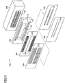
FIG. 1 illustrates an exploded, perspective view of a conventional inkjet head. -
FIG. 2 illustrates an exploded, perspective view of an inkjet head in an exemplary embodiment. -
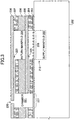
FIG. 3 illustrates a cross-sectional view of an ink channel within the inkjet head ofFIG. 2 in an exemplary embodiment. -
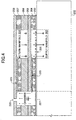
FIG. 4 illustrates a cross-sectional view of ink circulating through the ink channel in an exemplary embodiment. -
FIG. 5 illustrates an exploded, perspective view of an inkjet head in an exemplary embodiment. -
FIG. 6 is a cross-sectional view of an ink channel in the inkjet head ofFIG. 5 in an exemplary embodiment. -
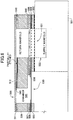
FIG. 7 is a cross-sectional view of ink circulating through the ink channel in a reverse direction in an exemplary embodiment. - The figures and the following description illustrate specific exemplary embodiments. It will thus be appreciated that those skilled in the art will be able to devise various arrangements that, although not explicitly described or shown herein, embody the principles of the embodiments and are included within the scope of the embodiments. Furthermore, any examples described herein are intended to aid in understanding the principles of the embodiments, and are to be construed as being without limitation to such specifically recited examples and conditions. As a result, the inventive concept(s) is not limited to the specific embodiments or examples described below, but by the claims.
-
FIG. 1 illustrates an exploded, perspective view of aconventional inkjet head 100.Inkjet head 100 forms a plurality of ink channels that are each capable of dispersing ink. Each ink channel includes a nozzle, a chamber for ink, and a mechanism for ejecting the ink from the chamber and through the nozzle, which is typically a diaphragm. - In this example,
inkjet head 100 includes ahousing 102, a series of plates 103-106, and apiezoelectric actuator 108.Housing 102 is a rigid member to which the plates 103-106 attach to forminkjet head 100.Housing 102 includes anopening 110 forpiezoelectric actuator 108 to pass through and interface with a diaphragm plate.Housing 102 further includes one ormore grooves 112 on a surface facing plates 103-106 for supplying ink to the ink channels. Groove 112 includes one ormore holes 113 that are in fluid communication with an ink reservoir. - The plates 103-106 of
inkjet head 100 are fixed or bonded to one another to form a laminated plate structure, and the laminated plate structure is affixed tohousing 102. The laminated plate structure includes the following plates: anorifice plate 106, achamber plate 105, arestrictor plate 104, and adiaphragm plate 103. Orificeplate 106 includes a plurality of nozzles 120 that are formed in one or more rows.Chamber plate 105 is formed with a plurality of chambers 121 that correspond with the nozzles 120 oforifice plate 106. The chambers 121 are each able to hold ink that is to be ejected out its corresponding nozzle.Restrictor plate 104 is formed with a plurality ofrestrictors 122. Therestrictors 122 fluidly connect chambers 121 to the ink supply, and control the flow of ink into chambers 121.Diaphragm plate 103 is formed withdiaphragms 123 andfilter sections 124.Diaphragms 123 each comprise a sheet of a semi-flexible material that vibrates in response to actuation bypiezoelectric actuator 108.Filter sections 124 remove foreign matter from ink entering into the ink channels. -
Piezoelectric actuator 108 includes a plurality ofpiezoelectric elements 130; one for each of the ink channels. The ends ofpiezoelectric elements 130contact diaphragms 123 indiaphragm plate 103. An external drive circuit (not shown) is able to selectively apply electrical signals topiezoelectric elements 130 which vibrate thediaphragm 123 for individual ink chambers. The vibration ofdiaphragms 123 changes the volume of the chambers 121, which in turn changes the pressure in the chambers 121. The change in pressure in a chamber 121 causes ink to be ejected from its corresponding nozzle 120.Inkjet head 100 can therefore print desired patterns by selectively "activating" the ink channels to discharge ink out of their respective nozzles. - When
inkjet head 100 is not in use for a period of time, or one or more of the ink channels is not in use during print operations for a period of time, the ink in the nozzles 120 and the chambers 121 can begin to dry. For example, ink that has a heavy pigment, magnetic ink, photopolymer materials used for three-dimensional (3D) printing, and the like can quickly begin to dry or harden in theinkjet head 100 when the ink channels are not used for printing. This can unfortunately cloginkjet head 100, which may require cleaning before the head can be used again for printing. To avoid clogging of an inkjet head, the following embodiments describe an inkjet head that is able to circulate (or recirculate) ink or other printing liquids/fluids within the inkjet head. In order to circulate ink, a return manifold is formed in the inkjet head. The return manifold is fluidly connected to the chambers of the ink channels through an additional restrictor plate proximate to the nozzles. The additional restrictor plate controls a flow of ink from the chambers (near the nozzles) into the return manifold. With this configuration, ink may be circulated within the inkjet head from the supply manifold, through the chambers, and into the return manifold so that the ink is less likely to dry within the inkjet head and clog the nozzles. -
FIG. 2 illustrates an exploded, perspective view of aninkjet head 200 in an exemplary embodiment. The inkjet heads as described herein, such asinkjet head 200, may be used for two-dimensional (2D) printing or three-dimensional (3D) printing. Therefore, inkjet heads may be implemented in an apparatus for printing, such as an inkjet printer. In this embodiment,inkjet head 200 includes a plurality of ink channels that are each capable of dispersing ink. Each channel includes a nozzle, a chamber for ink, and a mechanism for ejecting the ink from the chamber and through the nozzle, which is typically a diaphragm. The term "ink" as defined herein comprises any material, fluid, or liquid that may be applied by an inkjet head to a medium. The term "ink" does not solely refer to liquids that contain pigments or dyes, but may also refer to liquids that contain plastic filaments, photopolymers, etc., which are used for 3D printing. - In this embodiment,
inkjet head 200 includes ahousing 202, a series of plates 203-208, and apiezoelectric actuator 209.Housing 202 is a rigid member to which the plates 203-208 attach to forminkjet head 200.Housing 202 includes anopening 210 forpiezoelectric actuator 209 to pass through and interface with a diaphragm plate, which will be explained in more detail below.Housing 202 further includes agroove 212 on the surface facing plates 203-208 that encompasses or substantially surroundsopening 210.Groove 212 includes one ormore holes 213 that are in fluid communication with an ink reservoir, such as a supply reservoir. Therefore, groove 212 may represent a conduit for ink to travel from an ink reservoir to the individual ink channels in order to supply ink to the ink channels. The conduit (which includes groove 212) for supplying ink to the ink channels is referred to herein as a "supply manifold". -
Housing 202 further includes one ormore grooves 215 on the surface facing plates 203-208 that are separate or isolated fromgroove 212.Groove 215 includes one ormore holes 216 that are in fluid communication with another ink reservoir, such as a return reservoir. Therefore, groove 215 may represent a conduit for ink to travel out of the ink channels in inkjet head 200 (instead of out of the nozzles of the head) in order to circulate ink throughinkjet head 200. The conduit (which includes groove 215) for removing ink from the ink channels during circulation is referred to herein as a "return manifold". Although a supply reservoir and a return reservoir are described herein, a single reservoir may be used. - Plates 203-208 of
inkjet head 200 are fixed or bonded to one another to form a laminated plate structure, and the laminated plate structure is affixed tohousing 202. The plate structure illustrated inFIG. 2 is intended to be an example of a basic structure to show how circulation may be implemented ininkjet head 200. There may be additional plates that are used in the plate structure that are not shown inFIG. 2 . Also,FIG. 2 is not necessarily drawn to scale. - In this embodiment, the laminated plate structure includes the following plates: an
orifice plate 208, a firstrestrictor plate 207, chamber plates 205-206, a secondrestrictor plate 204, and adiaphragm plate 203.Orifice plate 208 includes a plurality ofnozzles 220 that are formed in one or more rows. Eachnozzle 220 represents an individual ink channel ininkjet head 200 for ejecting ink. Althoughinkjet head 200 is shown as having two rows of nozzles in this embodiment,inkjet head 200 may have a single row of nozzles or more rows of nozzles in other embodiments. - Chamber plates 205-206 are each formed with a plurality of
chambers 221 that correspond with thenozzles 220 oforifice plate 208.Chambers 221 may be referred to as "supply chambers" or "pressure chambers". Eachchamber 221 is an opening in chamber plate 205-206, and represents the portion of an ink channel that holds the ink which is ejected out itscorresponding nozzle 220. -
Chamber plate 206 is also formed withelongated openings 222 that are parallel to the row ofchambers 221, which are referred to as "return openings".Return openings 222 are slots that provide a further conduit for the ink to travel out of the ink channels in inkjet head 200 (instead of out of the nozzles of the head) in order to circulate ink throughinkjet head 200. Thus, returnopenings 222 are part of the return manifold forinkjet head 200.Chamber plate 205 is formed withreturn openings 224 that are part of the return manifold forinkjet head 200. Thereturn openings 224 inchamber plate 205 are positioned off to the side of the rows ofchambers 221. When bonded as a laminate, thereturn openings 224 inchamber plate 205 will partially overlap with thereturn openings 222 inchamber plate 206. Thereturn openings 224 inchamber plate 205 will also correspond withgrooves 215 inhousing 202 to form the return manifold. -
Restrictor plate 207 is sandwiched betweenorifice plate 208 andchamber plate 206.Restrictor plate 207 is formed with a plurality ofrestrictors 223. Therestrictors 223 fluidly connectchambers 221 to the return manifold. When ink is circulated throughinkjet head 200,restrictors 223 control the flow of ink that circulates out of thechambers 221 and into the return manifold. -
Restrictor plate 204 is sandwiched betweenchamber plate 205 anddiaphragm plate 203.Restrictor plate 204 is formed with a plurality ofrestrictors 225. Therestrictors 225 fluidly connectchambers 221 to the supply manifold, and control the flow of ink intochambers 221.Restrictor plate 204 is formed withreturn openings 226 that are part of the return manifold forinkjet head 200. Thereturn openings 226 inrestrictor plate 204 are positioned off to the side of the rows ofrestrictors 225. When bonded as a laminate, thereturn openings 226 inrestrictor plate 204 will correspond withgrooves 215 inhousing 202 to form the return manifold. -
Diaphragm plate 203 is formed withdiaphragms 227 and filtersections 228.Diaphragms 227 each comprise a sheet of a semi-flexible material that extends longitudinally to correspond with thechambers 221, and vibrates in response to actuation bypiezoelectric actuator 209.Filter sections 228 extend longitudinally to correspond with the supply manifold, and to remove foreign matter from ink flowing in the ink channels from the supply manifold. Althoughdiaphragm plate 203 is shown as including bothdiaphragms 227 and filtersections 228 in this embodiment,diaphragms 227 and filtersections 228 may be implemented in separate plates in other embodiments.Diaphragm plate 203 is also formed with return openings 229 that are part of the return manifold forinkjet head 200. The return openings 229 indiaphragm plate 203 are positioned off to the side of the rows ofdiaphragms 227. When bonded as a laminate, the return openings 229 indiaphragm plate 203 will correspond withgrooves 215 inhousing 202 to form the return manifold. -
Piezoelectric actuator 209 includes a plurality ofpiezoelectric elements 230; one for each of the ink channels. The ends ofpiezoelectric elements 230contact diaphragms 227 indiaphragm plate 203 at positions opposite thechambers 221. An external drive circuit (not shown) is able to selectively apply electrical signals topiezoelectric elements 230 which vibrate thediaphragm 227 for individual ink chambers. The vibration ofdiaphragms 227 changes the volume ofchambers 221, which in turn changes the pressure inchambers 221. The change in pressure in achamber 221 causes ink to be ejected from itscorresponding nozzle 220. -
FIG. 3 is a cross-sectional view of an ink channel ininkjet head 200 in an exemplary embodiment. The view inFIG. 3 is as if a slice where taken through the center of anozzle 220 inhead 200. The slice is then oriented inFIG. 3 with thenozzle 200 facing upward. Again, the plate structure illustrated inFIG. 3 is intended to be an example of a basic structure to show how circulation may be implemented ininkjet head 200. There may be additional plates that are used in the plate structure that are not shown inFIG. 3 . Also,FIG. 3 is not necessarily drawn to scale. - Beginning at the bottom of
FIG. 3 , thediaphragm plate 203 is shown as being connected tohousing 202. Thefilter section 228 ofdiaphragm plate 203 lines up with thesupply manifold 302 formed bygroove 212. Thediaphragm 227 ofdiaphragm plate 203 lines up with thechamber 221 of the ink channel.Restrictor plate 204 is sandwiched betweendiaphragm plate 203 and the chamber plates 205-206.Restrictor plate 204 includes restrictor 225 that controls a flow of ink from thesupply manifold 302 to thechamber 221 for the ink channel. - Chamber plates 205-206 form the
chamber 221 for the ink channel.Chamber plate 206 also forms thereturn manifold 304 for the ink to circulate through the ink channel.Restrictor plate 207 is sandwiched betweenchamber plate 206 andorifice plate 208.Restrictor plate 207 includes restrictor 223 that controls a flow of ink from thechamber 221 to thereturn manifold 304. The top plate inFIG. 3 isorifice plate 208 that has thenozzle 220 for the ink channel. -
FIG. 4 is a cross-sectional view of ink circulating through the ink channel in an exemplary embodiment. The ink flow is illustrated by the arrows inFIG. 4 . During a circulation, the ink flows intosupply manifold 302, as is illustrated by arrow points coming out of the page ofFIG. 4 . The ink then flows fromsupply manifold 302, through thefilter section 228 ofdiaphragm plate 203, and through the restrictor 225 in restrictor plate 204 (see alsoFIGS. 2-3 ). After passing through therestrictor 225, the ink flows into thechamber 221 of the ink channel formed by chamber plates 205-206. The ink then flows through the restrictor 223 in restrictor plate 207 (instead of exiting out of thenozzle 220 in orifice plate 208), and enters into return manifold 304 (see alsoFIGS. 2-3 ). The ink will then flow out ofreturn manifold 304, as is illustrated by arrow tails going into the page ofFIG. 4 . As is evident from this figure, circulation of ink ininkjet head 200 is possible becausereturn manifold 304 and anadditional restrictor 223 has been added to the ink channel to allow ink to flow out of thechamber 221 of an ink channel instead of sitting in thechamber 221 and potentially drying or settling. The flow directions shown inFIG. 4 are exemplary, and the actual flow of ink may depend on the position of the ink channel in theinkjet head 200. - As is evident from
FIGS. 3-4 ,restrictor 225 is formed on one end ofchamber 221 toward thediaphragm 227, andrestrictor 223 is formed on the other end ofchamber 221 toward thenozzle 220. The vertical position ofrestrictor 225 in the stack generally corresponds with the vertical position ofrestrictor 223 in the stack, with the chamber plates 205-206 separating the restrictors. Because of the way restrictors 223 and 225 are formed in the laminated structure, the vertical position ofreturn manifold 304 corresponds with the vertical position of thesupply manifold 302 in the laminated structure (i.e., returnmanifold 304 is formed on top ofsupply manifold 302 with a layer between them). This is advantageous because theinkjet head 200 can be made narrow, but is still able to circulate ink to avoid clogging. - In order to circulate ink as illustrated in
FIG. 4 , the pressure in thesupply manifold 302 and thereturn manifold 304 may be regulated. Drop-On-Demand (DOD) inkjet heads operate with slight negative pressure at their nozzles. This is to prevent ink from flowing out of the nozzles unintentionally. Wheninkjet head 200 is circulating ink, pressure at the supply manifold (P_in) and pressure at the return manifold (P_out) may be set as follows: - P_in = positive
- P_out = negative
- P_in + P_out = slightly negative at the nozzle(s)
- P_in - P_out = depends on the requirements (ink settling, drying prevention, and air removal, while still maintaining jetting stability).
- If a dual reservoir design is used, ink may be circulated by controlling the pressures for the reservoirs. The supply reservoir is regulated to have a positive pressure, while the return reservoir is regulated to have a negative pressure. The pressures are regulated in such a manner that the pressure at the nozzles are slightly negative. If a single reservoir design is used, then a pump may be placed in line with an inlet to the inkjet head to pump fluid into the head. Another pump may be placed in line with an outlet from the inkjet head to pump the fluid out of the head. The pumps may be used to regulate the positive pressure (inlets) and negative pressure (outlets) so that the pressure at the nozzles is slightly negative.
- The flow direction in
inkjet head 200 may also be reversed in other embodiments. Becauserestrictors inkjet head 200. Therefore, even thoughmanifold 302 is referred to as a "supply" manifold andmanifold 304 is referred to as a "return" manifold, the flow of ink throughinkjet head 200 may be reversed to be the opposite of that shown inFIG. 4 .FIG. 7 is a cross-sectional view of ink circulating through the ink channel in a reverse direction in an exemplary embodiment. During a circulation in this embodiment, the ink first flows intoreturn manifold 304, and then through the restrictor 223 intochamber 221 of the ink channel. The ink then flows through the restrictor 225 inrestrictor plate 204, and enters intosupply manifold 302. The ink will then flow out of the supply manifold. If the flow of ink is reversed in this manner, another filter plate may be used to filter the ink that enters throughreturn manifold 304. -
FIG. 5 illustrates an exploded, perspective view of aninkjet head 500 in an exemplary embodiment. The structure illustrated inFIG. 5 is just one particular example, and the embodiments described herein are not limited to the structure shown in the figure. In this example,inkjet head 500 includes ahousing 501 and a series of plates 502-512 that are fixed or bonded to one another to form a laminated plate structure.Housing 501 includes anopening 520 for a piezoelectric actuator (not shown).Housing 501 further includes asupply groove 522 that encompasses or substantially surroundsopening 520.Supply groove 522 forms the supply manifold forinkjet head 500.Housing 501 also includes returngrooves 523 that form the return manifold forinkjet head 500. -
Plate 502 is a filter plate that is porous (i.e., has many small holes that allow liquid to pass through), and removes foreign matter from the ink flowing in from the supply manifold.Filter plate 502 also includes an opening proximate to its center for the piezoelectric actuator to pass through.Plate 503 is a manifold plate that includeselongated supply openings 526 near its top and bottom for the supply manifold, and returnopenings 527 towards its ends (left and right inFIG. 5 ) for the return manifold.Manifold plate 503 further includeselongated openings 528 toward its center for piezoelectric elements of the actuator to pass through. -
Plate 504 is a diaphragm plate.Diaphragm plate 504 is formed withdiaphragms 530 and filtersections 531.Diaphragms 530 each comprise a sheet of a semi-flexible material that vibrates in response to actuation by a piezoelectric actuator.Filter sections 531 remove foreign matter from ink flowing from the supply manifold.Diaphragm plate 504 also includesreturn openings 532 towards its ends (left and right inFIG. 5 ) for the return manifold. -
Plate 505 is a support plate, andplate 506 is a restrictor plate.Support plate 505 is used in conjunction withrestrictor plate 506 to control the flow of ink through restrictors.Restrictor plate 506 includes parallel rows ofrestrictors 538. Arestrictor 538 is formed as an opening or aperture (which is vertical inFIG. 5 ), and onerestrictor 538 fromrestrictor plate 506 corresponds with one ink channel forinkjet head 500.Support plate 505 hasopenings 539 that correspond with therestrictors 538 inrestrictor plate 506 to control the flow of ink throughrestrictors 538.Support plate 505 andrestrictor plate 506 each include return openings 540-541, respectively, towards their ends (left and right inFIG. 5 ) that form the return manifold. -
Plate 507 is a chamber plate.Chamber plate 507 includes two parallel rows ofchambers 544. Achamber 544 is formed as an opening or aperture (which is vertical inFIG. 5 ), and onechamber 544 inchamber plate 507 corresponds with one ink channel forinkjet head 500. Achamber 544 represents the portion of an ink channel that holds the ink, and the pressure in thechamber 544 is changed to eject the ink out of its corresponding nozzle.Chamber plate 507 also includes return opening 546 towards its ends (left and right inFIG. 5 ) that form the return manifold. -
Plate 508 is also a chamber plate.Chamber plate 508 has a similar configuration aschamber plate 507 with parallel rows ofchambers 548. The return opening is different inchamber plate 508, which has anelongated opening 550 near its top and bottom for the return manifold instead of just toward its ends as withchamber plate 507. -
Plate 509 is also a chamber plate.Chamber plate 509 is configured with parallel row ofchambers 552. The size of the openings for thechambers 552 in this plate is illustrated as smaller than the openings for thechambers Chamber plate 509 also has an elongated return opening 554 near its top and bottom for the return manifold. -
Plate 510 is another chamber plate.Chamber plate 510 includes parallel rows ofchambers 556 like the other chamber plates.Chamber plate 510 also includes rows ofmanifold patterns 558. The portion ofmanifold patterns 558 nearest thechambers 556 are partially etched to assist in controlling the flow of ink from the chambers into the return manifold (in conjunction with restrictors in another restrictor plate 511). The portion ofmanifold pattern 558 towards the top and bottom ofchamber plate 510 are openings that form the return manifold. Although four chamber plates are illustrated inFIG. 5 , more or less chamber plates may be used to form the ink chambers as desired. -
Restrictor plate 511 includes parallel rows ofrestrictors 560. Arestrictor 560 is formed as an opening or aperture (which is vertical inFIG. 5 ), and onerestrictor 560 fromrestrictor plate 511 corresponds with one ink channel forinkjet head 500. The partially-etched sections of themanifold pattern 558 inchamber plate 510 correspond with therestrictors 560 inrestrictor plate 511 to control the flow of ink throughrestrictors 560 and into the return manifold. -
Plate 512 is an orifice plate.Orifice plate 512 includes parallel rows ofnozzles 566. A nozzle is a small aperture inorifice plate 512 from which ink may be ejected. Onenozzle 566 corresponds with one ink channel forinkjet head 500. -
FIG. 6 is a cross-sectional view of an ink channel ininkjet head 500 in an exemplary embodiment. The view inFIG. 6 is as if a slice were taken through the center of anozzle 566 inhead 500. The slice is then oriented inFIG. 6 with thenozzle 566 facing upward. Again, the plate structure illustrated inFIG. 6 is intended to be an example, as more or less plates may be used in other embodiments. Also,FIG. 6 is not necessarily drawn to scale. - Beginning at the bottom of
FIG. 6 ,filter plate 502 is sandwiched between thehousing 501 andmanifold plate 503.Diaphragm plate 504 is shown as being connected tomanifold plate 503. Thefilter section 531 ofdiaphragm plate 504 lines up with the supply manifold formed bygroove 522 in housing 501 (seeFIG. 5 ). Thediaphragm 530 ofdiaphragm plate 504 lines up with thechamber 544 of the ink channel. - Next,
support plate 505 is bonded todiaphragm plate 504, andrestrictor plate 506 is bonded to supportplate 505.Restrictor plate 506 includes arestrictor 538, that when used in conjunction withsupport plate 505, controls a flow of ink from the supply manifold to thechamber 544 for the ink channel. Followingrestrictor plate 506 are the chamber plates 507-510. Chamber plates 507-510 form thechamber 544 for the ink channel. Chamber plates 508-510 also form the return manifold for the ink to circulate through the ink channel. -
Restrictor plate 511 is sandwiched betweenchamber plate 510 andorifice plate 512.Restrictor plate 511 includes a restrictor 560 that controls a flow of ink from thechamber 544 to the return manifold. As described inFIG. 5 ,chamber plate 510 hasmanifold pattern 558 that is partially-etched as indicated inFIG. 6 to work in conjunction with the restrictor 560 in restrictor plate 517. Themanifold pattern 558 inchamber plate 510 also has an opening that forms the return manifold. The top plate inFIG. 6 isorifice plate 512 that has thenozzle 566 for the ink channel. - To circulate ink through the ink channel shown in
FIG. 6 , the pressure at the supply manifold (P_in) is adjusted to a positive pressure, and the pressure for the return manifold (P_out) is adjusted to a negative pressure so that the overall pressure of the ink channel is slightly negative (P_in + P_out = slightly negative at nozzle 566). This will cause ink to circulate through the ink channel without being ejected fromnozzle 566. The ink flows from the supply manifold, and through the restrictor 538 inrestrictor plate 506 intochamber 544. The ink then flows through the restrictor 560 in restrictor plate 511 (instead of exiting out of the nozzle 566), and enters into the return manifold. The ink will then flow out of the return manifold, and into a return reservoir. This circulation of the ink prevents the ink from sitting inchamber 544 and potentially drying or settling. - In another embodiment, the flow of ink through
inkjet head 500 may be reversed. During a circulation in this embodiment, the ink first flows into the return manifold. The ink then flows from the return manifold through the restrictor 560 closest to thenozzle 566 and intochamber 544 of the ink channel. The ink then flows through theother restrictor 538, and enters into the supply manifold. The ink will then flow out of the supply manifold. - Although specific embodiments were described herein, the scope of the invention is not limited to those specific embodiments. The scope of the invention is defined by the following claims.
- The present application is based on and claims the benefit of priority of
U.S. Patent Application No. 14/261,370 filed on April 24, 2014
Claims (10)
- An inkjet head (200) comprising:
a stack of plates including:an orifice plate (208) formed with a plurality of nozzles (220) through which ink droplets are ejected;a first restrictor plate (207);a chamber plate (206) that forms a plurality of chambers corresponding with the respective nozzles;a second restrictor plate (204); anda diaphragm plate (203) that has a diaphragm (227) for sealing the chambers;wherein a return manifold for circulating ink through the inkjet head is formed in the first restrictor plate (207), the chamber plate (206), the second restrictor plate (204), and the diaphragm plate (203) in the stack of plates;wherein the first restrictor plate (207) controls a flow of ink between the chambers and the return manifold;wherein the inkjet head further comprises a supply manifold formed in the diaphragm plate (203) and the second restrictor plate (204), and the second restrictor plate (204) controls the flow of ink between the supply manifold and the chambers,wherein a portion of the return manifold formed in the first restrictor plate (207) and the chamber plate (206), and the supply manifold are aligned in the stacking direction. - The inkjet head (200) of claim 1 further comprising:
a plurality of piezoelectric elements (230) attached to the diaphragm at positions opposite the chambers. - The inkjet head (200) of claim 2 further comprising:
a housing (202) that includes an opening (210) for the piezoelectric elements (230) to pass through to contact the diaphragm plate, and that includes a first groove (212) on a surface facing the diaphragm plate that encompasses the opening for the piezoelectric elements to form the supply manifold. - The inkjet head of claim 3 wherein:
the housing includes at least one second groove (215) on the surface for the return manifold. - The inkjet head of claim 4 further comprising:an inlet hole (213) in the first groove (212) of the housing that connects the supply manifold to a first reservoir; andan outlet hole in the at least one second groove of the housing that connects the return manifold to a second reservoir.
- The inkjet head (200) of claim 1 wherein:to circulate the ink from the supply manifold, through the chambers, and out through the return manifold,the pressure at the supply manifold (P_in) is positive;the pressure at the return manifold (P_out) is negative; andP in + P out is negative at the nozzles.
- The inkjet head (200) of claim 1 wherein the chamber plate (206) is a first chamber plate and comprises a first row of openings that form the chambers (221), and an elongated opening (222) parallel to the first row of openings that forms the return manifold,
wherein the inkjet head (200) further comprises a second chamber plate (205) including a second row of openings that form the chambers (221). - The inkjet head of claim 7 wherein:
the second chamber plate includes openings (224) set off to a side of the second row of openings that form the return manifold. - The inkjet head of claim 1 wherein:
the flow of ink is reversible in the ink channel. - An image forming apparatus comprising the inkjet head of any one of claims 1 to 9.
Applications Claiming Priority (2)
| Application Number | Priority Date | Filing Date | Title |
|---|---|---|---|
| US14/261,370 US9272514B2 (en) | 2014-04-24 | 2014-04-24 | Inkjet head that circulates ink |
| PCT/JP2015/063051 WO2015163487A1 (en) | 2014-04-24 | 2015-04-23 | Inkjet head that circulates ink |
Publications (3)
| Publication Number | Publication Date |
|---|---|
| EP3134265A1 EP3134265A1 (en) | 2017-03-01 |
| EP3134265A4 EP3134265A4 (en) | 2017-05-24 |
| EP3134265B1 true EP3134265B1 (en) | 2020-04-01 |
Family
ID=54332641
Family Applications (1)
| Application Number | Title | Priority Date | Filing Date |
|---|---|---|---|
| EP15782549.8A Active EP3134265B1 (en) | 2014-04-24 | 2015-04-23 | Inkjet head that circulates ink |
Country Status (6)
| Country | Link |
|---|---|
| US (4) | US9272514B2 (en) |
| EP (1) | EP3134265B1 (en) |
| JP (2) | JP6341296B2 (en) |
| CN (1) | CN106232365B (en) |
| AU (1) | AU2015250612B2 (en) |
| WO (1) | WO2015163487A1 (en) |
Families Citing this family (33)
| Publication number | Priority date | Publication date | Assignee | Title |
|---|---|---|---|---|
| US8255500B2 (en) | 2009-01-09 | 2012-08-28 | Ganart Technologies, Inc. | Remotely configurable user device with physical user resources and interface |
| US9272514B2 (en) * | 2014-04-24 | 2016-03-01 | Ricoh Company, Ltd. | Inkjet head that circulates ink |
| US11961105B2 (en) | 2014-10-24 | 2024-04-16 | Ganart Technologies, Inc. | Method and system of accretive value store loyalty card program |
| JP7016208B2 (en) | 2014-12-27 | 2022-02-04 | 株式会社リコー | Liquid discharge head, liquid discharge unit, liquid discharge device |
| AU2015375735B2 (en) | 2015-01-06 | 2019-02-14 | Ricoh Company, Ltd. | Liquid-discharging head, liquid-discharging unit, and device for discharging liquid |
| US9925785B2 (en) | 2015-09-30 | 2018-03-27 | Ricoh Company, Ltd. | Liquid discharge head, liquid discharge device, and liquid discharge apparatus |
| US10207509B2 (en) | 2015-10-01 | 2019-02-19 | Ricoh Company, Ltd. | Liquid discharge head, liquid discharge device, and liquid discharge apparatus |
| US20170182785A1 (en) * | 2015-12-23 | 2017-06-29 | Océ-Technologies B.V. | Inkjet printhead |
| JP6961930B2 (en) * | 2016-02-10 | 2021-11-05 | 株式会社リコー | Liquid discharge head, liquid discharge unit, liquid discharge device |
| US10000066B2 (en) * | 2016-02-10 | 2018-06-19 | Ricoh Company, Ltd. | Liquid discharge head, liquid discharge device, and liquid discharge apparatus |
| JP6870402B2 (en) * | 2016-03-16 | 2021-05-12 | 株式会社リコー | Ink set, yellow ink, ink container, inkjet printing device, inkjet printing method |
| US20170282544A1 (en) * | 2016-03-31 | 2017-10-05 | Xerox Corporation | Single jet recirculation in an inkjet print head |
| CN107344453A (en) * | 2016-05-06 | 2017-11-14 | 中国科学院苏州纳米技术与纳米仿生研究所 | A kind of piezoelectric ink jet printing equipment and preparation method thereof |
| JP6788221B2 (en) * | 2016-05-26 | 2020-11-25 | 株式会社リコー | Ink manufacturing method |
| CN109641456B (en) * | 2016-11-01 | 2021-06-15 | 惠普发展公司,有限责任合伙企业 | Fluid ejection device including fluid output channel |
| CN114889328B (en) * | 2017-03-29 | 2024-04-19 | 京瓷株式会社 | Liquid ejection head, recording device using the same, and recording method |
| CN107282371A (en) * | 2017-08-17 | 2017-10-24 | 京东方科技集团股份有限公司 | A kind of coating head and its apparatus for coating |
| JP7020021B2 (en) * | 2017-09-20 | 2022-02-16 | ブラザー工業株式会社 | Liquid discharge device |
| US11001070B2 (en) * | 2018-03-06 | 2021-05-11 | Ricoh Company, Ltd. | Independent reservoirs for supplying a print fluid to a flow-through printhead |
| JP7151372B2 (en) | 2018-03-13 | 2022-10-12 | セイコーエプソン株式会社 | LIQUID EJECTING HEAD AND LIQUID EJECTING APPARATUS |
| US10675865B2 (en) | 2018-03-30 | 2020-06-09 | Ricoh Company, Ltd. | Liquid discharge apparatus |
| JP7298147B2 (en) * | 2018-12-18 | 2023-06-27 | ブラザー工業株式会社 | liquid ejection head |
| JP7214468B2 (en) * | 2018-12-25 | 2023-01-30 | キヤノン株式会社 | liquid ejection head |
| JP7183809B2 (en) * | 2019-01-23 | 2022-12-06 | ブラザー工業株式会社 | liquid ejection head |
| JP7259417B2 (en) * | 2019-03-04 | 2023-04-18 | セイコーエプソン株式会社 | Liquid ejection head and liquid ejection device |
| US11034149B2 (en) | 2019-03-12 | 2021-06-15 | Ricoh Company, Ltd. | Flow-through printhead with bypass manifold |
| US10647125B1 (en) * | 2019-03-12 | 2020-05-12 | Ricoh Company, Ltd. | Fluid tank with flexible membrane for a flow-through printhead |
| JP7318277B2 (en) * | 2019-04-01 | 2023-08-01 | ブラザー工業株式会社 | Liquid ejection head and liquid ejection device |
| JP7417831B2 (en) | 2020-03-23 | 2024-01-19 | パナソニックIpマネジメント株式会社 | inkjet head |
| KR20220042030A (en) | 2020-09-25 | 2022-04-04 | 삼성디스플레이 주식회사 | Print head unit and inkjet printer including the same |
| JP2022070714A (en) * | 2020-10-27 | 2022-05-13 | ブラザー工業株式会社 | Liquid discharge head |
| US11571892B2 (en) | 2021-03-08 | 2023-02-07 | Ricoh Company, Ltd. | Manifold length in a printhead |
| US11801677B2 (en) | 2022-02-10 | 2023-10-31 | Ricoh Company, Ltd. | Printhead design with multiple fluid paths to jetting channels |
Family Cites Families (25)
| Publication number | Priority date | Publication date | Assignee | Title |
|---|---|---|---|---|
| US5087930A (en) * | 1989-11-01 | 1992-02-11 | Tektronix, Inc. | Drop-on-demand ink jet print head |
| US5155498A (en) * | 1990-07-16 | 1992-10-13 | Tektronix, Inc. | Method of operating an ink jet to reduce print quality degradation resulting from rectified diffusion |
| JPH06255101A (en) * | 1993-03-03 | 1994-09-13 | Seiko Epson Corp | Ink jet recording head |
| US5489930A (en) * | 1993-04-30 | 1996-02-06 | Tektronix, Inc. | Ink jet head with internal filter |
| JPH09150511A (en) * | 1995-11-30 | 1997-06-10 | Mita Ind Co Ltd | Ink jet head |
| GB9828476D0 (en) * | 1998-12-24 | 1999-02-17 | Xaar Technology Ltd | Apparatus for depositing droplets of fluid |
| GB0000368D0 (en) | 2000-01-07 | 2000-03-01 | Xaar Technology Ltd | Droplet deposition apparatus |
| JP2002103618A (en) * | 2000-01-17 | 2002-04-09 | Seiko Epson Corp | Ink jet recording head and its manufacturing method and ink jet recorder |
| US7077511B2 (en) | 2002-08-26 | 2006-07-18 | Ricoh Printing Systems Ltd. | Housing used in inkjet head |
| US7131718B2 (en) | 2003-06-20 | 2006-11-07 | Ricoh Printing Systems, Ltd. | Inkjet head and ejection device |
| JP4435112B2 (en) * | 2005-05-23 | 2010-03-17 | キヤノン株式会社 | Method for manufacturing liquid discharge head |
| EP1741556A1 (en) * | 2005-07-07 | 2007-01-10 | Agfa-Gevaert | Ink jet print head with improved reliability |
| JP4634258B2 (en) * | 2005-09-07 | 2011-02-16 | 株式会社アルバック | Print head, printing apparatus, and print head manufacturing method |
| JP4875997B2 (en) | 2007-02-16 | 2012-02-15 | 富士フイルム株式会社 | Liquid discharge head and liquid discharge apparatus |
| JP4855992B2 (en) * | 2007-03-30 | 2012-01-18 | 富士フイルム株式会社 | Liquid circulation device, image forming apparatus, and liquid circulation method |
| JP5003282B2 (en) * | 2007-05-23 | 2012-08-15 | 富士ゼロックス株式会社 | Droplet discharge head and image forming apparatus |
| JP2009154328A (en) * | 2007-12-25 | 2009-07-16 | Fuji Xerox Co Ltd | Liquid droplet discharge head and image forming apparatus equipped with the same |
| CN103640336B (en) * | 2008-05-23 | 2015-12-02 | 富士胶片株式会社 | Fluid droplet ejecting device |
| JP5563332B2 (en) * | 2009-02-26 | 2014-07-30 | 富士フイルム株式会社 | Apparatus for reducing crosstalk in supply and recovery channels during fluid droplet ejection |
| JP5430316B2 (en) * | 2009-09-18 | 2014-02-26 | 富士フイルム株式会社 | Image forming method |
| JP5495385B2 (en) * | 2010-06-30 | 2014-05-21 | 富士フイルム株式会社 | Droplet discharge head |
| JP5750753B2 (en) * | 2011-01-11 | 2015-07-22 | セイコーエプソン株式会社 | Liquid ejecting head and liquid ejecting apparatus |
| JP5953816B2 (en) | 2012-02-29 | 2016-07-20 | ブラザー工業株式会社 | Liquid ejection device |
| JP5911779B2 (en) | 2012-09-19 | 2016-04-27 | 富士フイルム株式会社 | Image recording apparatus and control method thereof |
| US9272514B2 (en) * | 2014-04-24 | 2016-03-01 | Ricoh Company, Ltd. | Inkjet head that circulates ink |
-
2014
- 2014-04-24 US US14/261,370 patent/US9272514B2/en active Active
-
2015
- 2015-04-23 WO PCT/JP2015/063051 patent/WO2015163487A1/en active Application Filing
- 2015-04-23 CN CN201580020194.4A patent/CN106232365B/en active Active
- 2015-04-23 JP JP2016563855A patent/JP6341296B2/en active Active
- 2015-04-23 AU AU2015250612A patent/AU2015250612B2/en active Active
- 2015-04-23 EP EP15782549.8A patent/EP3134265B1/en active Active
-
2016
- 2016-01-26 US US15/007,105 patent/US9630408B2/en active Active
- 2016-01-26 US US15/007,102 patent/US9604457B2/en active Active
-
2017
- 2017-03-14 US US15/458,765 patent/US9833994B2/en active Active
-
2018
- 2018-05-17 JP JP2018095367A patent/JP2018130967A/en active Pending
Non-Patent Citations (1)
| Title |
|---|
| None * |
Also Published As
| Publication number | Publication date |
|---|---|
| US9604457B2 (en) | 2017-03-28 |
| WO2015163487A1 (en) | 2015-10-29 |
| US20150306875A1 (en) | 2015-10-29 |
| US20160136955A1 (en) | 2016-05-19 |
| JP2017513740A (en) | 2017-06-01 |
| CN106232365B (en) | 2018-09-28 |
| EP3134265A4 (en) | 2017-05-24 |
| JP2018130967A (en) | 2018-08-23 |
| CN106232365A (en) | 2016-12-14 |
| US9833994B2 (en) | 2017-12-05 |
| US9630408B2 (en) | 2017-04-25 |
| EP3134265A1 (en) | 2017-03-01 |
| AU2015250612B2 (en) | 2017-08-10 |
| JP6341296B2 (en) | 2018-06-13 |
| US20170182777A1 (en) | 2017-06-29 |
| AU2015250612A1 (en) | 2016-11-03 |
| US9272514B2 (en) | 2016-03-01 |
| US20160136962A1 (en) | 2016-05-19 |
Similar Documents
| Publication | Publication Date | Title |
|---|---|---|
| EP3134265B1 (en) | Inkjet head that circulates ink | |
| US8657420B2 (en) | Fluid recirculation in droplet ejection devices | |
| JP4839274B2 (en) | Inkjet head, inkjet recording apparatus | |
| US20050243146A1 (en) | Recirculation assembly | |
| JP5726969B2 (en) | Printhead reservoir with a filter placed outside the ink ejection path | |
| US11155086B2 (en) | Fluidic ejection devices with enclosed cross-channels | |
| KR20070009728A (en) | Elongated filter assembly | |
| US20210291547A1 (en) | Fluidic ejection dies with enclosed cross-channels | |
| US9919521B2 (en) | Liquid ejection head | |
| EP3689614B1 (en) | Liquid discharge head, liquid discharge apparatus, and method of controlling the liquid discharge head | |
| JP7172369B2 (en) | LIQUID EJECTION HEAD AND LIQUID EJECTION APPARATUS | |
| JP6407032B2 (en) | Liquid discharge head and liquid discharge apparatus | |
| JP2021011085A (en) | Liquid discharge head and liquid discharge device | |
| JP2023110060A (en) | Liquid discharge head |
Legal Events
| Date | Code | Title | Description |
|---|---|---|---|
| STAA | Information on the status of an ep patent application or granted ep patent |
Free format text: STATUS: THE INTERNATIONAL PUBLICATION HAS BEEN MADE |
|
| PUAI | Public reference made under article 153(3) epc to a published international application that has entered the european phase |
Free format text: ORIGINAL CODE: 0009012 |
|
| STAA | Information on the status of an ep patent application or granted ep patent |
Free format text: STATUS: REQUEST FOR EXAMINATION WAS MADE |
|
| 17P | Request for examination filed |
Effective date: 20161007 |
|
| AK | Designated contracting states |
Kind code of ref document: A1 Designated state(s): AL AT BE BG CH CY CZ DE DK EE ES FI FR GB GR HR HU IE IS IT LI LT LU LV MC MK MT NL NO PL PT RO RS SE SI SK SM TR |
|
| AX | Request for extension of the european patent |
Extension state: BA ME |
|
| A4 | Supplementary search report drawn up and despatched |
Effective date: 20170424 |
|
| RIC1 | Information provided on ipc code assigned before grant |
Ipc: B41J 2/14 20060101AFI20170418BHEP Ipc: B41J 2/18 20060101ALI20170418BHEP |
|
| DAV | Request for validation of the european patent (deleted) | ||
| DAX | Request for extension of the european patent (deleted) | ||
| STAA | Information on the status of an ep patent application or granted ep patent |
Free format text: STATUS: EXAMINATION IS IN PROGRESS |
|
| 17Q | First examination report despatched |
Effective date: 20190603 |
|
| GRAP | Despatch of communication of intention to grant a patent |
Free format text: ORIGINAL CODE: EPIDOSNIGR1 |
|
| STAA | Information on the status of an ep patent application or granted ep patent |
Free format text: STATUS: GRANT OF PATENT IS INTENDED |
|
| INTG | Intention to grant announced |
Effective date: 20191118 |
|
| GRAS | Grant fee paid |
Free format text: ORIGINAL CODE: EPIDOSNIGR3 |
|
| GRAA | (expected) grant |
Free format text: ORIGINAL CODE: 0009210 |
|
| STAA | Information on the status of an ep patent application or granted ep patent |
Free format text: STATUS: THE PATENT HAS BEEN GRANTED |
|
| RIN1 | Information on inventor provided before grant (corrected) |
Inventor name: VO, GIANG Inventor name: NISHIMURA, HIROSHI Inventor name: MATSUMORI, CONNOR |
|
| AK | Designated contracting states |
Kind code of ref document: B1 Designated state(s): AL AT BE BG CH CY CZ DE DK EE ES FI FR GB GR HR HU IE IS IT LI LT LU LV MC MK MT NL NO PL PT RO RS SE SI SK SM TR |
|
| REG | Reference to a national code |
Ref country code: GB Ref legal event code: FG4D |
|
| REG | Reference to a national code |
Ref country code: CH Ref legal event code: EP Ref country code: AT Ref legal event code: REF Ref document number: 1250862 Country of ref document: AT Kind code of ref document: T Effective date: 20200415 |
|
| REG | Reference to a national code |
Ref country code: DE Ref legal event code: R096 Ref document number: 602015049916 Country of ref document: DE |
|
| REG | Reference to a national code |
Ref country code: IE Ref legal event code: FG4D |
|
| PG25 | Lapsed in a contracting state [announced via postgrant information from national office to epo] |
Ref country code: BG Free format text: LAPSE BECAUSE OF FAILURE TO SUBMIT A TRANSLATION OF THE DESCRIPTION OR TO PAY THE FEE WITHIN THE PRESCRIBED TIME-LIMIT Effective date: 20200701 |
|
| REG | Reference to a national code |
Ref country code: NL Ref legal event code: MP Effective date: 20200401 |
|
| REG | Reference to a national code |
Ref country code: LT Ref legal event code: MG4D |
|
| PG25 | Lapsed in a contracting state [announced via postgrant information from national office to epo] |
Ref country code: LT Free format text: LAPSE BECAUSE OF FAILURE TO SUBMIT A TRANSLATION OF THE DESCRIPTION OR TO PAY THE FEE WITHIN THE PRESCRIBED TIME-LIMIT Effective date: 20200401 Ref country code: PT Free format text: LAPSE BECAUSE OF FAILURE TO SUBMIT A TRANSLATION OF THE DESCRIPTION OR TO PAY THE FEE WITHIN THE PRESCRIBED TIME-LIMIT Effective date: 20200817 Ref country code: CZ Free format text: LAPSE BECAUSE OF FAILURE TO SUBMIT A TRANSLATION OF THE DESCRIPTION OR TO PAY THE FEE WITHIN THE PRESCRIBED TIME-LIMIT Effective date: 20200401 Ref country code: NL Free format text: LAPSE BECAUSE OF FAILURE TO SUBMIT A TRANSLATION OF THE DESCRIPTION OR TO PAY THE FEE WITHIN THE PRESCRIBED TIME-LIMIT Effective date: 20200401 Ref country code: IS Free format text: LAPSE BECAUSE OF FAILURE TO SUBMIT A TRANSLATION OF THE DESCRIPTION OR TO PAY THE FEE WITHIN THE PRESCRIBED TIME-LIMIT Effective date: 20200801 Ref country code: FI Free format text: LAPSE BECAUSE OF FAILURE TO SUBMIT A TRANSLATION OF THE DESCRIPTION OR TO PAY THE FEE WITHIN THE PRESCRIBED TIME-LIMIT Effective date: 20200401 Ref country code: GR Free format text: LAPSE BECAUSE OF FAILURE TO SUBMIT A TRANSLATION OF THE DESCRIPTION OR TO PAY THE FEE WITHIN THE PRESCRIBED TIME-LIMIT Effective date: 20200702 Ref country code: NO Free format text: LAPSE BECAUSE OF FAILURE TO SUBMIT A TRANSLATION OF THE DESCRIPTION OR TO PAY THE FEE WITHIN THE PRESCRIBED TIME-LIMIT Effective date: 20200701 Ref country code: SE Free format text: LAPSE BECAUSE OF FAILURE TO SUBMIT A TRANSLATION OF THE DESCRIPTION OR TO PAY THE FEE WITHIN THE PRESCRIBED TIME-LIMIT Effective date: 20200401 |
|
| REG | Reference to a national code |
Ref country code: AT Ref legal event code: MK05 Ref document number: 1250862 Country of ref document: AT Kind code of ref document: T Effective date: 20200401 |
|
| PG25 | Lapsed in a contracting state [announced via postgrant information from national office to epo] |
Ref country code: LV Free format text: LAPSE BECAUSE OF FAILURE TO SUBMIT A TRANSLATION OF THE DESCRIPTION OR TO PAY THE FEE WITHIN THE PRESCRIBED TIME-LIMIT Effective date: 20200401 Ref country code: HR Free format text: LAPSE BECAUSE OF FAILURE TO SUBMIT A TRANSLATION OF THE DESCRIPTION OR TO PAY THE FEE WITHIN THE PRESCRIBED TIME-LIMIT Effective date: 20200401 Ref country code: RS Free format text: LAPSE BECAUSE OF FAILURE TO SUBMIT A TRANSLATION OF THE DESCRIPTION OR TO PAY THE FEE WITHIN THE PRESCRIBED TIME-LIMIT Effective date: 20200401 |
|
| REG | Reference to a national code |
Ref country code: CH Ref legal event code: PL |
|
| PG25 | Lapsed in a contracting state [announced via postgrant information from national office to epo] |
Ref country code: AL Free format text: LAPSE BECAUSE OF FAILURE TO SUBMIT A TRANSLATION OF THE DESCRIPTION OR TO PAY THE FEE WITHIN THE PRESCRIBED TIME-LIMIT Effective date: 20200401 |
|
| REG | Reference to a national code |
Ref country code: DE Ref legal event code: R097 Ref document number: 602015049916 Country of ref document: DE |
|
| PG25 | Lapsed in a contracting state [announced via postgrant information from national office to epo] |
Ref country code: RO Free format text: LAPSE BECAUSE OF FAILURE TO SUBMIT A TRANSLATION OF THE DESCRIPTION OR TO PAY THE FEE WITHIN THE PRESCRIBED TIME-LIMIT Effective date: 20200401 Ref country code: ES Free format text: LAPSE BECAUSE OF FAILURE TO SUBMIT A TRANSLATION OF THE DESCRIPTION OR TO PAY THE FEE WITHIN THE PRESCRIBED TIME-LIMIT Effective date: 20200401 Ref country code: LI Free format text: LAPSE BECAUSE OF NON-PAYMENT OF DUE FEES Effective date: 20200430 Ref country code: EE Free format text: LAPSE BECAUSE OF FAILURE TO SUBMIT A TRANSLATION OF THE DESCRIPTION OR TO PAY THE FEE WITHIN THE PRESCRIBED TIME-LIMIT Effective date: 20200401 Ref country code: SM Free format text: LAPSE BECAUSE OF FAILURE TO SUBMIT A TRANSLATION OF THE DESCRIPTION OR TO PAY THE FEE WITHIN THE PRESCRIBED TIME-LIMIT Effective date: 20200401 Ref country code: AT Free format text: LAPSE BECAUSE OF FAILURE TO SUBMIT A TRANSLATION OF THE DESCRIPTION OR TO PAY THE FEE WITHIN THE PRESCRIBED TIME-LIMIT Effective date: 20200401 Ref country code: MC Free format text: LAPSE BECAUSE OF FAILURE TO SUBMIT A TRANSLATION OF THE DESCRIPTION OR TO PAY THE FEE WITHIN THE PRESCRIBED TIME-LIMIT Effective date: 20200401 Ref country code: CH Free format text: LAPSE BECAUSE OF NON-PAYMENT OF DUE FEES Effective date: 20200430 Ref country code: IT Free format text: LAPSE BECAUSE OF FAILURE TO SUBMIT A TRANSLATION OF THE DESCRIPTION OR TO PAY THE FEE WITHIN THE PRESCRIBED TIME-LIMIT Effective date: 20200401 Ref country code: LU Free format text: LAPSE BECAUSE OF NON-PAYMENT OF DUE FEES Effective date: 20200423 Ref country code: DK Free format text: LAPSE BECAUSE OF FAILURE TO SUBMIT A TRANSLATION OF THE DESCRIPTION OR TO PAY THE FEE WITHIN THE PRESCRIBED TIME-LIMIT Effective date: 20200401 |
|
| REG | Reference to a national code |
Ref country code: BE Ref legal event code: MM Effective date: 20200430 |
|
| PLBE | No opposition filed within time limit |
Free format text: ORIGINAL CODE: 0009261 |
|
| STAA | Information on the status of an ep patent application or granted ep patent |
Free format text: STATUS: NO OPPOSITION FILED WITHIN TIME LIMIT |
|
| PG25 | Lapsed in a contracting state [announced via postgrant information from national office to epo] |
Ref country code: SK Free format text: LAPSE BECAUSE OF FAILURE TO SUBMIT A TRANSLATION OF THE DESCRIPTION OR TO PAY THE FEE WITHIN THE PRESCRIBED TIME-LIMIT Effective date: 20200401 Ref country code: BE Free format text: LAPSE BECAUSE OF NON-PAYMENT OF DUE FEES Effective date: 20200430 Ref country code: PL Free format text: LAPSE BECAUSE OF FAILURE TO SUBMIT A TRANSLATION OF THE DESCRIPTION OR TO PAY THE FEE WITHIN THE PRESCRIBED TIME-LIMIT Effective date: 20200401 |
|
| 26N | No opposition filed |
Effective date: 20210112 |
|
| PG25 | Lapsed in a contracting state [announced via postgrant information from national office to epo] |
Ref country code: IE Free format text: LAPSE BECAUSE OF NON-PAYMENT OF DUE FEES Effective date: 20200423 |
|
| PG25 | Lapsed in a contracting state [announced via postgrant information from national office to epo] |
Ref country code: SI Free format text: LAPSE BECAUSE OF FAILURE TO SUBMIT A TRANSLATION OF THE DESCRIPTION OR TO PAY THE FEE WITHIN THE PRESCRIBED TIME-LIMIT Effective date: 20200401 |
|
| PG25 | Lapsed in a contracting state [announced via postgrant information from national office to epo] |
Ref country code: TR Free format text: LAPSE BECAUSE OF FAILURE TO SUBMIT A TRANSLATION OF THE DESCRIPTION OR TO PAY THE FEE WITHIN THE PRESCRIBED TIME-LIMIT Effective date: 20200401 Ref country code: MT Free format text: LAPSE BECAUSE OF FAILURE TO SUBMIT A TRANSLATION OF THE DESCRIPTION OR TO PAY THE FEE WITHIN THE PRESCRIBED TIME-LIMIT Effective date: 20200401 Ref country code: CY Free format text: LAPSE BECAUSE OF FAILURE TO SUBMIT A TRANSLATION OF THE DESCRIPTION OR TO PAY THE FEE WITHIN THE PRESCRIBED TIME-LIMIT Effective date: 20200401 |
|
| PG25 | Lapsed in a contracting state [announced via postgrant information from national office to epo] |
Ref country code: MK Free format text: LAPSE BECAUSE OF FAILURE TO SUBMIT A TRANSLATION OF THE DESCRIPTION OR TO PAY THE FEE WITHIN THE PRESCRIBED TIME-LIMIT Effective date: 20200401 |
|
| P01 | Opt-out of the competence of the unified patent court (upc) registered |
Effective date: 20230522 |
|
| PGFP | Annual fee paid to national office [announced via postgrant information from national office to epo] |
Ref country code: FR Payment date: 20230424 Year of fee payment: 9 Ref country code: DE Payment date: 20230420 Year of fee payment: 9 |
|
| PGFP | Annual fee paid to national office [announced via postgrant information from national office to epo] |
Ref country code: GB Payment date: 20230419 Year of fee payment: 9 |