EP3134044B1 - Appareil chirurgical de vitrectomie utilisant une rétroaction de pression à multiples capteurs - Google Patents
Appareil chirurgical de vitrectomie utilisant une rétroaction de pression à multiples capteurs Download PDFInfo
- Publication number
- EP3134044B1 EP3134044B1 EP15721436.2A EP15721436A EP3134044B1 EP 3134044 B1 EP3134044 B1 EP 3134044B1 EP 15721436 A EP15721436 A EP 15721436A EP 3134044 B1 EP3134044 B1 EP 3134044B1
- Authority
- EP
- European Patent Office
- Prior art keywords
- pressure
- vitrectomy
- valve
- sensors
- duty cycle
- Prior art date
- Legal status (The legal status is an assumption and is not a legal conclusion. Google has not performed a legal analysis and makes no representation as to the accuracy of the status listed.)
- Active
Links
Images


Classifications
-
- A—HUMAN NECESSITIES
- A61—MEDICAL OR VETERINARY SCIENCE; HYGIENE
- A61F—FILTERS IMPLANTABLE INTO BLOOD VESSELS; PROSTHESES; DEVICES PROVIDING PATENCY TO, OR PREVENTING COLLAPSING OF, TUBULAR STRUCTURES OF THE BODY, e.g. STENTS; ORTHOPAEDIC, NURSING OR CONTRACEPTIVE DEVICES; FOMENTATION; TREATMENT OR PROTECTION OF EYES OR EARS; BANDAGES, DRESSINGS OR ABSORBENT PADS; FIRST-AID KITS
- A61F9/00—Methods or devices for treatment of the eyes; Devices for putting-in contact lenses; Devices to correct squinting; Apparatus to guide the blind; Protective devices for the eyes, carried on the body or in the hand
- A61F9/007—Methods or devices for eye surgery
- A61F9/00736—Instruments for removal of intra-ocular material or intra-ocular injection, e.g. cataract instruments
-
- A—HUMAN NECESSITIES
- A61—MEDICAL OR VETERINARY SCIENCE; HYGIENE
- A61B—DIAGNOSIS; SURGERY; IDENTIFICATION
- A61B17/00—Surgical instruments, devices or methods, e.g. tourniquets
- A61B17/32—Surgical cutting instruments
-
- A—HUMAN NECESSITIES
- A61—MEDICAL OR VETERINARY SCIENCE; HYGIENE
- A61F—FILTERS IMPLANTABLE INTO BLOOD VESSELS; PROSTHESES; DEVICES PROVIDING PATENCY TO, OR PREVENTING COLLAPSING OF, TUBULAR STRUCTURES OF THE BODY, e.g. STENTS; ORTHOPAEDIC, NURSING OR CONTRACEPTIVE DEVICES; FOMENTATION; TREATMENT OR PROTECTION OF EYES OR EARS; BANDAGES, DRESSINGS OR ABSORBENT PADS; FIRST-AID KITS
- A61F9/00—Methods or devices for treatment of the eyes; Devices for putting-in contact lenses; Devices to correct squinting; Apparatus to guide the blind; Protective devices for the eyes, carried on the body or in the hand
- A61F9/007—Methods or devices for eye surgery
- A61F9/00736—Instruments for removal of intra-ocular material or intra-ocular injection, e.g. cataract instruments
- A61F9/00763—Instruments for removal of intra-ocular material or intra-ocular injection, e.g. cataract instruments with rotating or reciprocating cutting elements, e.g. concentric cutting needles
-
- A—HUMAN NECESSITIES
- A61—MEDICAL OR VETERINARY SCIENCE; HYGIENE
- A61B—DIAGNOSIS; SURGERY; IDENTIFICATION
- A61B17/00—Surgical instruments, devices or methods, e.g. tourniquets
- A61B2017/00017—Electrical control of surgical instruments
- A61B2017/00137—Details of operation mode
- A61B2017/00154—Details of operation mode pulsed
- A61B2017/00194—Means for setting or varying the repetition rate
-
- A—HUMAN NECESSITIES
- A61—MEDICAL OR VETERINARY SCIENCE; HYGIENE
- A61B—DIAGNOSIS; SURGERY; IDENTIFICATION
- A61B17/00—Surgical instruments, devices or methods, e.g. tourniquets
- A61B2017/00367—Details of actuation of instruments, e.g. relations between pushing buttons, or the like, and activation of the tool, working tip, or the like
- A61B2017/00411—Details of actuation of instruments, e.g. relations between pushing buttons, or the like, and activation of the tool, working tip, or the like actuated by application of energy from an energy source outside the body
-
- A—HUMAN NECESSITIES
- A61—MEDICAL OR VETERINARY SCIENCE; HYGIENE
- A61B—DIAGNOSIS; SURGERY; IDENTIFICATION
- A61B17/00—Surgical instruments, devices or methods, e.g. tourniquets
- A61B2017/00535—Surgical instruments, devices or methods, e.g. tourniquets pneumatically or hydraulically operated
- A61B2017/00544—Surgical instruments, devices or methods, e.g. tourniquets pneumatically or hydraulically operated pneumatically
-
- A—HUMAN NECESSITIES
- A61—MEDICAL OR VETERINARY SCIENCE; HYGIENE
- A61B—DIAGNOSIS; SURGERY; IDENTIFICATION
- A61B90/00—Instruments, implements or accessories specially adapted for surgery or diagnosis and not covered by any of the groups A61B1/00 - A61B50/00, e.g. for luxation treatment or for protecting wound edges
- A61B90/06—Measuring instruments not otherwise provided for
- A61B2090/064—Measuring instruments not otherwise provided for for measuring force, pressure or mechanical tension
- A61B2090/065—Measuring instruments not otherwise provided for for measuring force, pressure or mechanical tension for measuring contact or contact pressure
Definitions
- the present invention relates generally to the field of surgical repair of retinal disorders, and more specifically to the efficient operation of pneumatic vitrectomy devices during ophthalmic surgical procedures.
- Vitrectomy surgery has been successfully employed in the treatment of particular ocular problems, such as retinal detachments resulting from tears or holes in the retina. Vitrectomy surgery typically involves removal of vitreous gel and may utilize three small incisions in the pars plana of the patient's eye. These incisions allow the surgeon to pass three separate instruments into the patient's eye to affect the ocular procedure.
- the surgical instruments typically include a vitreous cutting device, an illumination source, and an infusion port.
- Current vitreous cutting devices may employ a "guillotine" type action wherein a sharp-ended inner rigid cutting tube moves axially inside an outer sheathing tube.
- the eye material e.g. vitreous gel or fibers
- the eye material is cleaved into sections small enough to be removed through the hollow center of the inner cutting tube.
- Vitreous cutters are available in either electric or pneumatic form.
- Today's electric cutters may operate within a range of speeds typically between 750 - 2500 cuts-per-minute (CPM) where pneumatic cutters may operate over a range of speeds between 100 - 2500 CPM.
- the surgeon may make adjustments to control the pneumatic vitrectomy surgical instrument cutting speed, i.e. controlling the cutting device using a surgical handpiece, in order to perform different activities during the corrective procedure.
- Corrective procedures may include correction of macular degeneration, retinal detachment, macular pucker, and addressing eye injuries.
- the cutting device within a pneumatic handpiece requires precise control of applied pressure to overcome the internal spring return mechanism to assure the quality of each cutting stroke.
- Such systems have typically employed a fluid (typically air) reservoir or accumulator to collect fluid and from which fluid is drawn to effectuate the cut valve using pneumatic pressure.
- the frequency of opening and closing the pneumatic valve i.e. the time interval between each opening cycle of the valve, is varied to achieve the desired cutting speed.
- a relatively large fluid reservoir or accumulator is needed.
- a large fluid reservoir is undesirable in today's operating environment where smaller components are favored.
- inconsistent pressure can be provided to the cut valve in even the best of circumstances, and in the case of minor leaks, inconsistent pressure is practically a given. Even minor pressure inconsistencies can be highly undesirable.
- calibration settings can accommodate for relatively fixed environmental factors, such as altitude, but rapidly changing environmental factors such as temperature or electro-mechanical pump variations in virtually all situations cannot be adequately addressed using calibration techniques.
- US 2011/0054508 A1 discloses a pneumatic pressure output control by drive valve duty cycle calibration.
- US 2011/0295293 A1 discloses a feedback control of on/off pneumatic actuators.
- US 2003/0195538 A1 discloses a high-speed vitreous cutting system.
- a vitrectomy apparatus comprising a pressure source, a cut valve connected to the pressure source, the cut valve configured to be turned on and off to provide pressure to selectively extend and retract a vitrectomy cutting device, a plurality of sensors provided at a plurality of points between the pressure source and a vitrectomy handpiece, and a controller configured to selectively provide commands to change pressure source duty cycle according to a plurality of linear functions when one sensor of the plurality of sensors measures a pressure outside a predetermined pressure range.
- the apparatus is suitable for controlling a vitrectomy system, by sensing pressure provided from a pressure source through a cut valve and to a vitrectomy handpiece using a plurality of sensors positioned between the pressure source and the vitrectomy handpiece, and controlling operation of the cut valve based on pressure measured by altering a function when measured pressure from one of the plurality of sensors is outside a predetermined pressure range.
- the present design provides a system and method for high-speed pneumatic vitrectomy control and operation that employs pressure feedback at various points in the pneumatic line, thereby reducing or eliminating the need for a fluid reservoir or accumulator space in a vitrectomy machine. Such a design enables more accurate and efficient cutting of the vitreous material.
- the present design is directed to accurate, reliable, and efficient control of the cutting speed of the blade in a pneumatic vitrectomy handpiece used in a medical instrument system.
- the present design will be discussed herein with a particular emphasis on a medical or hospital environment where a surgeon or health care practitioner performs.
- an embodiment of the present design is a phacoemulsification surgical system that comprises an integrated high-speed control module for the vitrectomy handpiece.
- the surgeon may adjust or set the cutting speed via a graphical user interface (GUI) module or a foot pedal switch to control the high-speed pneumatic vitrectomy handpiece.
- GUI graphical user interface
- FIGs. 1A and 1B are high-level conceptual block diagrams illustrating a common vitrectomy system's pneumatic cutting mechanism located within a surgical handpiece provided for purposes of explaining the present invention.
- FIG. 1A shows the pneumatic cutting mechanism in the "cut,” “closed port,” or “forward” position
- FIG. 1B shows the pneumatic cutting mechanism in the "initial,” “open port,” or “backward” position.
- construction of pneumatic cutter devices typically involve a blade 110 positioned to work or operate against a spring 120 by inflating and deflating a bladder 130 configured to move blade 110 by 'pushing' blade 110 forward to a forward position 175 when bladder 130 is inflated and 'pulling' blade 110 backward using the energy stored in spring 120 to its resting position or initial position 170 when bladder 130 is deflated.
- the desired cutting speed may be realized by filling and emptying bladder 130 in a cyclical manner through an air passage 140 arranged for receiving a pressurized airburst in the direction indicated at point 150. The received pressurized air burst is then evacuated or vented in direction 160.
- FIGs. 1A and 1B A combination input pressurized air supply and output air venting valve mechanism 195, or valve, is represented in FIGs. 1A and 1B .
- Valve 195 may be configured to provide a pressurized airburst when the valve is open, filling bladder 130 and venting the air within bladder 130 when the valve is closed to empty the bladder.
- Increasing the frequency of the control signal cycling rate which produces a shorter pressurized air burst time, generally results in an increased cutting speed, or an increased number of cuts-per-minute as observed at the knife or blade.
- a subsequent decrease in control signal cycling rate generally produces a slower or decreased cutting speed.
- FIG. 2A One example control signal to instruct the opening and closing of valve 195 associated with air passage 140 is shown in FIG. 2A .
- the control signal illustrated in FIG. 2A may cycle between valve-off (V O ) at point 210 and valve-on (V E ) at point 220, or provide a valve-energized instruction at a predetermined cycling rate, thereby effectuating the desired cutting speed.
- FIG. 2B illustrates an example pressure waveform resulting from the application of the control signal shown in FIG. 2A .
- the waveform is shown to have a constant rise in pressure up to a peak pressure (P P ) at 230 when the valve is energized.
- P P peak pressure
- a subsequent drop in pressure to a residual pressure (P R ) at point 240 occurs when the valve is de-energized.
- the cycling in pressure, for controlling the blade forward and backward reciprocating movements, as illustrated by the waveform shown in FIG. 2B may produce a specific cutting speed for blade 110 in terms of cuts-per-minute.
- Pneumatic cutter designs have been configured with a speed control device to select and vary the rate the blade mechanism moves forward and backward to effectuate cutting.
- changing the speed of the blade may involve varying the time or duration of the control signal provided to the valve.
- By increasing the open period and closed period of valve 195 the resultant blade speed is reduced.
- decreasing the amount of time valve 195 is open and closed causes the blade speed to increase.
- FIG. 2C An example of a control signal for controlling the filling and emptying of air in bladder 130 with an increase in cycle time is illustrated in FIG. 2C .
- the control signal cyclic frequency is set at a lower rate than after time t 1 to illustrate the surgeon selecting an increase in cutting speed at time t 1 during a surgical procedure.
- FIG. 2D illustrates an example pressure waveform resulting from the application of the control signal shown in FIG. 2C . This pressure waveform reflects the control signal change that occurred at time t 1 at 250, and may drive blade 110 at a faster rate.
- the pneumatic vitrectomy handpiece is used in connection with a phaco-vitrectomy module and may be part of a phacoemulsification machine.
- a handpiece may include a "guillotine" type cutter pneumatically driven to either an open or closed position. Opening and closing occurs via air pressure provided via a flexible line or delivery line between the cutter and a pneumatic driver.
- the pneumatic driver may include a pressure source, such as a pump, configured to fill a small reservoir or accumulator with compressed air at its maximum pressure capacity.
- accumulator and “reservoir” are used interchangeably and are intended to mean the same fluid (typically air) buffering or holding device.
- the output of this reservoir is connected to a pressure regulator that may regulate the air pressure down to the level required by the cutter, as shown by peak P P and residual P R pressure in FIG. 2B .
- a smaller reservoir may be supplied or fed by the regulator output, forming the source for the delivery valve.
- the cutter in the present vitrectomy embodiment is pneumatic, while the cut valve actuation is electrical.
- the pulsing discussed is an electrical signal transmitted from the control module. When the electrical pulse drops to a non-energized state, a vent is opened resulting in a drop in pressure that functions to enable the force of a spring to overcome the resultant pressure, and the cutter returns to an initial state.
- the electronic controller may be connected to the delivery valve and may provide instructions to produce a pulse width (in time) of pressurized air when the valve is open.
- the controller may be arranged to provide fixed pulses of pressurized air within the flexible line in a manner that drives the cutter.
- the electronic controller may use a fixed pulse timing control signal to instruct the delivery valve to open and close.
- the fixed timing, or fixed duration, control signal instructs the delivery valve to open and close in a constant cyclical manner.
- control functionality can be characterized as "open-loop," or without any type of feedback. Cutting speeds, etc. are simply set by a surgeon or user and effectuated, and changes in conditions or parameters in the environment are unaccounted for.
- FIG. 3 is a block diagram illustrating components and devices for a previous version of a pneumatic vitreous cutting module 305 integrated within a phacoemulsification machine 300 in accordance with the present design. Although depicted as an integral unit, module 305 functionality may be realized by using multiple devices to perform the functionality disclosed.
- a compressed air source 310 and associated air check valve 311 may supply air pressure for pneumatic vitreous cutting module 305.
- the compressed air source 310 typically comprises a pump (not shown) configured to both provide a pneumatic, typically a gas such as air, supply pressure to the cut valve and a vent mechanism to relieve pressure to atmospheric conditions. Compressed air source 310 thus provides a source of vacuum or pressure.
- Compressed air is provided by the pump via delivery line 301 illustrated between air check valve 311 and pre-regulator 312.
- Check valve 311 is typically arranged with two ports and may allow air pressure to flow through in one direction, from compressed air source 310 to pre-regulator 312.
- the pump may pump pressurized air into a high pressure chamber, not shown, which in turn provides high pressure air to pre-regulator 312 via delivery line 301.
- the high-pressure chamber or compressed air source 310 may provide a stable source of air at a higher pressure than the working pressure of the cutter.
- pressure source or the “compressed air source” means any device or arrangement that is configured to provide a source of pressure or vacuum, including but not limited to a pump or Venturi device, compressed air supply, compressed air inlet supply, or any device provided within a vitrectomy machine or originating from an external source that provides pressure or vacuum, such as a pressure source provided through a wall of a building, e.g. via a wall mounted nozzle or device, an external pressure source such as an external pump, or otherwise.
- a pressure source provided through a wall of a building, e.g. via a wall mounted nozzle or device, an external pressure source such as an external pump, or otherwise.
- the terms are therefore intended to be interpreted broadly.
- Pre-regulator 312 may provide a workable steady air pressure stream from which compressed air source 310 may supply air pressure for pressure regulator 313 via delivery line 302.
- Pressure regulator 313 may be preset to a desired pressure and may be configured to provide air to accumulator 314 at a low,-steady, and safe operating pressure.
- Pressure regulator 313 may connect directly to compressed air source 310, typically a pump, but alternately a high pressure chamber, by a delivery line and input high pressure and regulate the air pressure to a lower value consistent with the operating pressure of the cutter handpiece.
- Accumulator 314 may operate as a working pressure chamber, and may receive pressurized air at specific pressure and volume from pressure regulator 313 via delivery line 303. Accumulator 314 may provide a specific amount of air pressure at a predetermined volume to cut valve 316 via delivery line 304 such that no excess pressure is forced into the delivery line 307.
- Controller 320 which may provide a graphical user interface, computes a cut rate based on physician input (programmed and/or the footpedal position) or the preprogrammed maximum cut rate and/or the footpedal position and electronically provides a desired or computed cut rate to cut valve 316 via communications control line 306.
- the controller 320 may take different forms, including comprising a PCBA (printed circuit board assembly), or may be part of a PCBA, ASIC, or other hardware design.
- a storage unit (not shown) may be provided to store certain values used by the controller 320 during the vitrectomy procedure, including settings desired by the surgeon and other relevant data.
- Cut valve 316 may open and close in response to the control signal provided from controller 320.
- Controller 320 electronically controls the valves operating the regulated pressure and/or vacuum air sent to the cutter.
- the handpiece blade motion may move in a forward and backward reciprocating motion in response to the pressure waveform provided via delivery line 307.
- controller 320 may operate cut valve 316 to deliver a pulse of regulated air pressure to delivery line 307 and the cutter (not shown). While the surgeon or practitioner may select variations in the pulse repetition frequency, once the selection is made, the system seeks to attain the desired cutting rate.
- Cut valve 316 is electronically controlled by controller 320 to transmit pressure, and cut valve 316 opens and closes at a precise time to allow air at a specific pressure and volume to fill the delivery line 307 and operate the cutter. Cut valve 316 may connect to atmospheric pressure for purposes of venting air received from delivery line 307. Controller 320 may provide an electronic indication to cut valve 316 that originates with a user selected switch, such as a switch on the handpiece, graphical user interface, or a foot switch. Line 308 represents the electrical connection between controller 320 and compressed air source 310.
- the present design employs pressure feedback at multiple points in the line between the compressed air source 310 and valve 195, and feedback of the pressures at the various points is employed in a specific manner to control cut pressure.
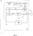
- FIG. 4 illustrates an embodiment of a vitrectomy device according to the present design.
- sensors 401, 402, and 403 are provided, where sensor 401 is provided at the cut valve 195, sensor 402 is provided between the compressed air source 310 and the pre-regulator 312, and sensor 403 is provided between pressure regulator 313 and accumulator 314.
- Each of sensors 401, 402, and 403 provide signals to controller 320, typically in the form of current pressure sensed.
- the present design includes a vitrectomy apparatus having a compressed air source such as a pump, a cut valve connected to the pump, the cut valve configured to be turned on and off to provide pressure to selectively extend and retract a vitrectomy cutting device, a plurality of sensors configured to sense pressure provided along the line between the pump and the vitrectomy cutting device, and a controller configured to control the duty cycle of the pump based on a linear function selected based on pressure sensed by the plurality of sensors.
- the pressure source comprises a pump having a pump core and a pressure regulator configured to control pressure supplied from the pump core.
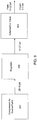
- FIG. 5 presents an alternate embodiment of the present design.
- FIG. 5 shows compressed air source 501, regulator 502, accumulator 503, and cut valve 504 in a single line and connected as shown.
- Pressure sensor 511 measures or senses (collectively, “measures") pressure at cut valve 504, while pressure sensor 513 measures pressure at a point between regulator 502 and accumulator 503.
- Pressure sensor 512 measures the pressure between compressed air source 501 and regulator 502. As shown, each of sensors 511, 512, and 513 feeds information to controller 520, which then controls compressed air source 501 based on information received from the sensors.
- pressure sensor 511 measures pressure and in conjunction with the controller 520 determines whether the peak value during a period of time is between a first set minimum and maximum allowable value. These components also determine whether the measured value of pressure sensor 513 is between a third set of minimum and maximum values, while pressure sensor 512 and controller 520 determine whether the pressure at the pressure sensor 512 is between a second set of minimum and maximum values.
- each sensor comprises a passage configured to monitor pneumatic pressure at a point between the compressed air source and the vitrectomy cutting device, and the controller comprises circuitry configured to provide signals to control the pump duty cycle based on a linear function selected based on pressure sensed or measured by the plurality of sensors.
- FIG. 4 illustrates the sensor 402 provided between the compressed air source 310 and the pre-regulator 312, however in an embodiment the sensor may be placed elsewhere, such as between pre-regulator 312 and pressure regulator 313.
- FIG. 6 is a simplified view of the present design reflecting certain maximum and minimum predetermined pressure values employed in a particular arrangement. Numbers presented are generally representative but may change depending on circumstances and equipment employed. From FIG. 6 , compressed air source 601 provides pressure to regulator 602 in an expected range of between about 25 and 45 psi. Pressure between regulator 602 and cut valve 603 is expected to be between about 21 and 27 psi. Pressure at cut valve 603 is expected to have a trough, or lowest, value of between zero and three psi, with a peak between 14 and 22 psi, irrespective of cut speed. Again, these are representative values and actual values may differ, but the values may differ between the three sensors as far as acceptable pressure ranges. While three sensors are shown in this embodiment, it is to be understood that any number of sensors may be employed that is typically greater than one.
- the controller such as controller 320 in FIG. 3 , employs a function, typically a linear function, to drive the speed of the compressed air source 310 or pump 601 to deliver a relatively steady source of pressure to the cut valve.
- Controller 320 monitors the sensors, typically at a very rapid rate such as in the tens of milliseconds. If the pressure at any sensor of the multiple sensors varies outside the expected range, the system changes the function (e.g. linear function) employed. In an embodiment, if the pressure at any sensor of the multiple sensors varies outside the expected range, the system changes the function employed by increasing or decreasing a linear function constant depending upon whether greater or lower pressure is required.
- FIG. 7 illustrates representative duty cycle graphs or curves according to one aspect of the present design.
- the y axis of FIG. 7 represents the motor duty cycle, i.e. the speed of the motor driving the compressed air source, while the x axis represents the cut rate.
- these curves are representative of expected curves and values in a typical setting, but the values may differ for different settings, components, and/or circumstances, and any number of curves may be employed.
- eight curves are shown as an example, and each of the curves 701a-h may be employed depending on circumstances.
- a default curve may be employed and a different curve employed as time progresses, e.g. a curve above or below the default curve may be selected depending on pressures encountered.
- x represents the cut rate desired, or provided by the surgeon or operator.
- the requested cut rate may be 1200 CPM.
- MinDuty is the minimum acceptable duty cycle, in percent, and a number as low as 10 is not unusual in certain operations. For an example minimum duty cycle of 10 per cent, Equation (1) would provide (1/100) * 1200 + (10-1), or a value of 21 for the motor duty cycle.
- the value 1/100 is generally calculated as the maximum duty cycle minus the minimum duty cycle desired for performance over the range divided by the maximum cut rate minus the minimum cut rate expected for the device.
- numbers may vary depending on circumstances including cut range and pump duty cycles, a number such as 1/100 may be appropriate in certain instances.
- Cut rate in certain pneumatic applications may be, for example, between 100 and 1200 CPM.
- duty cycle varies based on the pump motor employed, but in some circumstances, a minimum duty cycle of 10 per cent and a maximum duty cycle of 45 per cent is not unexpected.
- the present design switches between functions, in this embodiment between linear functions, when one of the three sensors senses a pressure above a highest value or below a lowest value, the controller 320 changes the function to adapt to changes in environment. Such a design may serve to maintain or improve cut pressure even when a leak is present in the system or more specifically in the line.
- the linear function constant is incremented resulting in the duty cycle being incremented if not already at an upper limit. If pressure at any of the sensors is greater than the corresponding threshold, the linear function constant is decremented resulting in the duty cycle being decremented if not already at a lower limit.
- the result is a new function, i.e. a new linear function when pressure is outside an expected range, when the linear function is not already at an upper or lower limit.
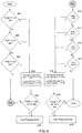
- FIG. 8 is a general flowchart depicting operation of the controller based on sensed pressures. From FIG. 8 , operation begins at point 801 and runs through low pressure evaluation and adjustment. Note that the particular functions depicted in FIG. 8 may occur in any order or in different groupings than shown. For example, FIG. 8 shows making low pressure assessments and adjustments before high pressure assessments and adjustments, but these may reversed, and/or ordering of the sensors evaluated and pressures addressed may differ from the depiction shown. At point 801, the system assesses the cutter sensor, e.g. first sensor 511 in FIG. 5 , and determines if the peak value is less than or equal to a predetermined value, shown as 14 psi in this embodiment.
- the cutter sensor e.g. first sensor 511 in FIG. 5
- the system determines whether pressure sensed at, for example, third sensor 513 in FIG. 5 , and the pressure is evaluated as being less than or equal to a predetermined level, in this embodiment 21 psi. Again, if the pressure is less than or equal to, operation transitions to point 804, but if not, operation passes to point 803, wherein pressure sensed at second pressure sensor 512 in FIG. 5 , is evaluated. If the pressure at second pressure sensor 512 is less than or equal to a predetermined amount, such as 25 psi, operation transitions to point 804. If not, this indicates that every sensor has sensed a pressure above the requisite minimums, and operation transitions in this embodiment to high pressure sensing and adjustment.
- Point 804 indicates that the minimum duty cycle is increased to less than or equal to a desired value, such as 34 psi, and the maximum duty cycle is also increased to less than or equal to a desired value, such as 45 psi.
- Point 805 evaluates whether the peak value has been less than an acceptable value for a predetermined amount of time. If not, there is no current issue, and processing progresses to high pressure assessment and adjustment. If so, a low pressure error exists, which may be any number of problems including but not limited to a severe break in the line(s). In this failure situation, failure processing may occur, including providing warnings and/or shutting down operation in a safe and approved manner.
- the system assesses the cutter sensor, e.g. first sensor 511 in FIG. 5 , and determines if the trough value is greater than a predetermined value, shown as 3 psi in this embodiment. If the trough or lowest value sensed is greater than this predetermined value, operation progresses to point 814, but if not, operation progresses to point 811.
- the system determines whether the peak value is greater than a predetermined value, in this embodiment greater than 22 psi. If so, operation progresses to point 814, and if not, operation progresses to point 812.
- a predetermined level in this embodiment 45 psi. Again, if the pressure is greater, operation transitions to point 814, but if not, operation passes to point 813, wherein pressure sensed at third pressure sensor 513 in FIG. 5 , is evaluated. If the pressure at third pressure sensor 513 is greater than a predetermined amount, such as 27 psi, operation transitions to point 814. If not, this indicates that every sensor has sensed a pressure below the established maximums, and operation is complete for this functionality.
- Point 814 indicates that the minimum duty cycle is decreased to a value of greater than or equal to a desired value, such as 10 psi, and the maximum duty cycle is also decreased to greater than or equal to a desired value, such as 21 psi.
- Point 815 evaluates whether the trough value has been greater than a predetermined value for a certain amount of time. If not, there is no current issue, and processing ends. If so, a high pressure error exists. In this failure situation, failure processing may occur, including providing warnings and/or shutting down operation, again in a safe and approved manner.
- the present design takes pressure readings from multiple positions along the line and alters functions when the pressures sensed are above or below predetermined values. In this manner, a more robust maintenance of cutting pressure, either at a high cutting speed or a low cutting speed, is maintained without the need for a large accumulator.
- Sensor measurements may be evaluated at an appropriate rate, such as in the tens of milliseconds, e.g. from between 10 to 100 milliseconds.
- Advantages may be gained by evaluating at different points along the path before others; for example, if concern is great regarding pressure at the cut valve, the cut valve sensor may be evaluated first. If concern is greatest regarding compressed air source pressure, the sensor closest to the compressed air source may be evaluated first. Evaluations may be done in parallel or in any order desired, and operation is not in any way limited to the depiction provided in FIG. 8 .
- FIG. 9 illustrates closed loop control of the compressed air source or pump according to an embodiment of the present design.
- FIG. 9 illustrates the vitreous cutter running continuously and stepped from a low value to a high value, in one embodiment from 100 CPM to 1200 CPM.
- Pump motor duty cycle labeled as Speed in FIG. 9 , shows that compensation follows the same basic stepping pattern as the requested cut rate, labeled as Cut-Rate in FIG. 9 . While the duty cycle follows the stepping pattern of the requested cut rate, the peak pressure, labeled Peak, as well as the pump pressure (PS2) and the regulator pressure (PS3) are consistent in amplitude.
- PS2 pump pressure
- PS3 regulator pressure
- FIG. 9 specifically represents one embodiment, with PS2 (line 901) being pump pressure in psi, ranging from 21 to 45 psi, PS3 (line 902) being regulator pressure in psi, from 21 to 25, Peak (line 903) being a peak pressure level, from 14 to 22 psi, Trough (line 904) being a trough or low pressure between 0 and3 psi.
- Speed (line 905) represents the speed of the compressed air source motor
- Cut Rate (line 906) represents the cut rate.
- the x axis of FIG. 9 represents time, while the y axis is motor duty cycle, or pressure in psi, or cut rate divided by 100 depending on the variable.
- FIG. 10 shows an example vitreous cutter making repeated single cuts.
- the data shows the effect of the compensating closed-loop software control of the duty cycles of the pneumatic pump, i.e. the effect of the linear functions.
- the corresponding data for the pump motor duty cycle (Speed, line 1005) shows the compensation for each single cut remains consistent as does peak pressure, labeled as Peak (line 1003), pressure at the pump, labeled PS2 (line 1001), and pressure at the regulator, labeled PS3 (line 1002).
- Peak peak
- PS2 pressure at the pump
- PS3 pressure at the regulator
- PS2 (line 1001) being pump pressure in psi, ranging from 21 to 45 psi
- PS3 (line 1002) being regulator pressure in psi, from 21 to 25, Peak (line 1003) being a peak pressure level, from 14 to 22 psi, Trough (line 1004) being a trough or low pressure between 0 and 4 psi.
- Speed (line 1005) represents the duty cycle of the compressed motor source.
- the x axis of FIG. 10 represents time, while the y axis is motor duty cycle or pressure in psi depending on the variable.
- Pneumatic devices driven by varying pressures may include devices used for cutting, hammering, or lifting.
- the present design includes a vitrectomy apparatus, comprising a pressure source, a cut valve connected to the pressure source, the cut valve configured to be turned on and off to provide pressure to selectively extend and retract a vitrectomy cutting device, a plurality of sensors provided at a plurality of points between the pressure source and the cut valve, and a controller configured to employ a function correlating a desired cut rate with a pressure source duty cycle and employ a different function when one sensor of the plurality of sensors senses a pressure outside a predetermined pressure range.
- the present design is a method for performing a vitrectomy procedure, comprising sensing pressure provided from a pressure source through a cut valve and to a vitrectomy handpiece using a plurality of sensors positioned between the pressure source and the vitrectomy cutting device, and controlling operation of the cut valve based on pressure sensed by altering a function when sensed pressure from one of the plurality of sensors is outside a predetermined pressure range.
- a vitrectomy apparatus comprising a vitrectomy handpiece comprising a vitrectomy cutting device, a sensing arrangement comprising a plurality of sensors configured to sense pressure, tubing connecting the vitrectomy handpiece to the sensing arrangement, a cut valve connected to the sensing arrangement, a pressure source configured to provide pressure to the cut valve, and a controller configured to receive data from the sensor arrangement and selectively provide commands to change pressure source duty cycle according to a plurality of linear functions according to data received from the sensor arrangement.
- DSP digital signal processor
- ASIC application specific integrated circuit
- FPGA field programmable gate array
- a general purpose processor may be a microprocessor, but in the alternative, the processor may be any conventional processor, controller, microcontroller, or state machine.
- a processor may also be implemented as a combination of computing devices, e.g., a combination of a DSP and a microprocessor, a plurality of microprocessors, one or more microprocessors in conjunction with a DSP core, or any other such configuration.
- a software module may reside in RAM memory, flash memory, ROM memory, EPROM memory, EEPROM memory, DOM memory, registers, hard disk, a removable disk, a CD-ROM, or any other form of storage medium known in the art.
- An exemplary storage medium is coupled to the processor such the processor can read information from, and write information to, the storage medium.
- the storage medium may be integral to the processor.
- the processor and the storage medium may reside in an ASIC.
- the ASIC may reside in a user terminal.
- the processor and the storage medium may reside as discrete components in a user terminal.
Claims (7)
- Appareil de vitrectomie, comprenant :une source de pression (310) ;une valve de coupure (316) reliée à la source de pression, la valve de coupure étant conçue pour être activée et désactivée afin de fournir une pression pour étendre et rétracter sélectivement un dispositif de coupe pour vitrectomie ;une pluralité de capteurs (401, 402, 403) situés au niveau d'une pluralité de points entre la source de pression et une pièce à main pour vitrectomie ; etun organe de commande (320) conçu pour fournir sélectivement des commandes afin de changer le cycle de service de la source de pression selon une fonction sélectionnée parmi une pluralité de fonctions (701a à 701h) lorsqu'un capteur de la pluralité de capteurs mesure une pression en dehors d'une plage de pression prédéfinie.
- Appareil de vitrectomie selon la revendication 1, dans lequel la fonction est une fonction linéaire.
- Appareil de vitrectomie selon la revendication 1 ou 2, dans lequel la source de pression comprend une pompe comprenant un coeur de pompe et un régulateur de pression conçu pour commander la pression fournie par le coeur de pompe.
- Appareil de vitrectomie selon la revendication 1, 2 ou 3, dans lequel chaque capteur comprend un passage conçu pour surveiller la pression pneumatique en un point entre la valve de coupure et le dispositif de coupe pour vitrectomie.
- Appareil de vitrectomie selon la revendication 4, dans lequel l'organe de commande est conçu pour surveiller la pression et commander le cycle de service sur la base de relevés reçus de trois capteurs positionnés entre la source de pression et la pièce à main pour vitrectomie.
- Appareil de vitrectomie selon l'une quelconque des revendications précédentes, dans lequel l'organe de commande est conçu pour :
changer la fonction, ce qui permet de changer le cycle de service de la source de pression lorsqu'une pression détectée reçue d'un capteur de la pluralité de capteurs est en dehors d'une plage de pression prédéfinie. - Appareil de vitrectomie selon l'une quelconque des revendications précédentes, comprenant en outre :une pièce à main pour vitrectomie comprenant le dispositif de coupe pour vitrectomie ; etun tube reliant la pièce à main pour vitrectomie à la valve de coupure.
Applications Claiming Priority (2)
| Application Number | Priority Date | Filing Date | Title |
|---|---|---|---|
| US201461983310P | 2014-04-23 | 2014-04-23 | |
| PCT/US2015/027012 WO2015164459A1 (fr) | 2014-04-23 | 2015-04-22 | Appareil chirurgical de vitrectomie utilisant une rétroaction de pression à multiples capteurs |
Publications (2)
| Publication Number | Publication Date |
|---|---|
| EP3134044A1 EP3134044A1 (fr) | 2017-03-01 |
| EP3134044B1 true EP3134044B1 (fr) | 2018-10-03 |
Family
ID=53059460
Family Applications (1)
| Application Number | Title | Priority Date | Filing Date |
|---|---|---|---|
| EP15721436.2A Active EP3134044B1 (fr) | 2014-04-23 | 2015-04-22 | Appareil chirurgical de vitrectomie utilisant une rétroaction de pression à multiples capteurs |
Country Status (5)
| Country | Link |
|---|---|
| US (1) | US9775742B2 (fr) |
| EP (1) | EP3134044B1 (fr) |
| AU (1) | AU2015249789B2 (fr) |
| CA (1) | CA2946723A1 (fr) |
| WO (1) | WO2015164459A1 (fr) |
Families Citing this family (4)
| Publication number | Priority date | Publication date | Assignee | Title |
|---|---|---|---|---|
| DE102017208584A1 (de) * | 2017-05-22 | 2018-11-22 | Geuder Ag | Vorrichtung zur Bereitstellung von Druckluftimpulsen für ein ophthalmologisches Instrument und ein Steuerungsverfahren für solch eine Vorrichtung |
| DE102017220263A1 (de) * | 2017-11-14 | 2019-05-16 | Geuder Ag | Vorrichtung und Verfahren zum Schneiden und Absaugen von Gewebe aus dem menschlichen oder tierischen Körper |
| US11106191B2 (en) * | 2018-09-19 | 2021-08-31 | Hypertherm, Inc. | Multi-sensor analysis and data point correlation for predictive monitoring and maintenance of a pressurized fluid cutting system |
| CN116301086B (zh) * | 2023-05-16 | 2023-09-05 | 图湃(北京)医疗科技有限公司 | 玻璃体切割机、用于玻璃体切割机的监测方法及装置 |
Family Cites Families (49)
| Publication number | Priority date | Publication date | Assignee | Title |
|---|---|---|---|---|
| GB1221678A (en) | 1967-12-22 | 1971-02-03 | Kawasaki Heavy Ind Ltd | Improvements in and relating to the control of the pressure of gas generated from a converter |
| US3882872A (en) | 1970-01-05 | 1975-05-13 | Nicholas G Douvas | Method and apparatus for cataract surgery |
| US4314560A (en) | 1979-11-28 | 1982-02-09 | Helfgott Maxwell A | Powered handpiece for endophthalmic surgery |
| US4768506A (en) | 1985-09-26 | 1988-09-06 | Alcon Laboratories, Inc. | Handpiece drive apparatus for powered surgical scissors |
| US5417246A (en) | 1989-10-27 | 1995-05-23 | American Cyanamid Company | Pneumatic controls for ophthalmic surgical system |
| US5279547A (en) | 1991-01-03 | 1994-01-18 | Alcon Surgical Inc. | Computer controlled smart phacoemulsification method and apparatus |
| US5403276A (en) | 1993-02-16 | 1995-04-04 | Danek Medical, Inc. | Apparatus for minimally invasive tissue removal |
| US6258111B1 (en) | 1997-10-03 | 2001-07-10 | Scieran Technologies, Inc. | Apparatus and method for performing ophthalmic procedures |
| US5788667A (en) | 1996-07-19 | 1998-08-04 | Stoller; Glenn | Fluid jet vitrectomy device and method for use |
| US6010496A (en) | 1996-08-29 | 2000-01-04 | Bausch & Lomb Surgical, Inc. | Vitrectomy timing device with microcontroller with programmable timers |
| DE19717790A1 (de) | 1997-04-26 | 1998-10-29 | Convergenza Ag | Vorrichtung mit einem therapeutischen Katheter |
| CN1348342A (zh) | 1999-02-17 | 2002-05-08 | 奥普特克斯眼科公司 | 从哺乳动物眼睛中摘除晶状体的方法、设备及系统 |
| US6599271B1 (en) | 1999-04-13 | 2003-07-29 | Syntec, Inc. | Ophthalmic flow converter |
| US6290690B1 (en) | 1999-06-21 | 2001-09-18 | Alcon Manufacturing, Ltd. | Simultaneous injection and aspiration of viscous fluids in a surgical system |
| US6514268B2 (en) | 1999-08-30 | 2003-02-04 | Alcon Universal Ltd. | Method of operating microsurgical instruments |
| US6575990B1 (en) | 1999-10-21 | 2003-06-10 | Medical Instrument Development Laboratories, Inc. | High speed vitreous cutting system |
| AU2626401A (en) | 2000-01-03 | 2001-07-16 | Johns Hopkins University, The | Surgical devices and methods of use thereof for enhanced tactile perception |
| WO2002069808A2 (fr) | 2000-11-06 | 2002-09-12 | Suros Surgical Systems, Inc. | Appareil de biopsie |
| IL156831A0 (en) | 2001-01-18 | 2004-02-08 | Univ California | Minimally invasive glaucoma surgical instrument and method |
| US6599277B2 (en) | 2001-11-30 | 2003-07-29 | Bausch & Lomb Incorporated | Aspiration flow meter and control |
| US20050096682A1 (en) | 2003-11-05 | 2005-05-05 | Visibelle Derma Institute, Inc. | Vibratory blade device for body treatments |
| US20070078506A1 (en) | 2004-04-13 | 2007-04-05 | Mccormick Paul | Method and apparatus for decompressing aneurysms |
| US20070173870A2 (en) | 2005-10-18 | 2007-07-26 | Jaime Zacharias | Precision Surgical System |
| US7967777B2 (en) | 2006-11-09 | 2011-06-28 | Abbott Medical Optics Inc. | Eye treatment system with multiple pumps |
| US9241830B2 (en) | 2006-12-15 | 2016-01-26 | Novartis Ag | Pressure monitor for pneumatic vitrectomy machine |
| DK2094173T3 (en) | 2006-12-21 | 2016-06-06 | Doheny Eye Inst | Disposable vitrectomy handpiece |
| WO2008079526A2 (fr) | 2006-12-22 | 2008-07-03 | Alcon Research, Ltd. | Procédé d'actionnement d'un instrument microchirurgical |
| US8109937B2 (en) | 2007-02-23 | 2012-02-07 | Alcon Research, Ltd. | Surgical system for indication of media types |
| US8323271B2 (en) | 2007-04-20 | 2012-12-04 | Doheny Eye Institute | Sterile surgical tray |
| US8460324B2 (en) | 2008-04-15 | 2013-06-11 | Abbott Medical Optics Inc. | High speed pneumatic vitrectomy control |
| US20140114336A1 (en) | 2012-10-24 | 2014-04-24 | Gregory P. Schmitz | Minimally invasive micro tissue debriders having targeted rotor positions |
| US9279751B2 (en) | 2008-12-16 | 2016-03-08 | Nico Corporation | System and method of taking and collecting tissue cores for treatment |
| US8854221B2 (en) | 2008-12-19 | 2014-10-07 | Bausch & Lomb Incorporated | System to identify viscosity of aspirated material during ophthalmic surgery |
| US9561129B2 (en) | 2009-01-07 | 2017-02-07 | Rodney L. Ross | Tissue removal devices, systems and methods |
| CA2770487C (fr) | 2009-08-31 | 2018-01-09 | Jiansheng Zhou | Regulation de la sortie de pression pneumatique par etalonnage du cycle de service d'une vanne de commande |
| RU2556529C2 (ru) | 2009-12-10 | 2015-07-10 | Алькон Рисерч, Лтд. | Система и способы для динамического привода пневматического клапана |
| US8821524B2 (en) * | 2010-05-27 | 2014-09-02 | Alcon Research, Ltd. | Feedback control of on/off pneumatic actuators |
| US8298253B2 (en) | 2010-05-27 | 2012-10-30 | Alcon Research, Ltd. | Variable drive vitrectomy cutter |
| US8920335B2 (en) | 2010-09-01 | 2014-12-30 | Alcon Research, Ltd. | Methods and systems for posterior segment volume measurement |
| EP2611370A2 (fr) | 2010-09-03 | 2013-07-10 | University of Washington | Dispositifs neurochirurgicaux et systèmes et méthodes associés |
| US8888802B2 (en) | 2010-12-21 | 2014-11-18 | Alcon Research, Ltd. | Vitrectomy probe with adjustable cutter port size |
| US9101441B2 (en) | 2010-12-21 | 2015-08-11 | Alcon Research, Ltd. | Vitrectomy probe with adjustable cutter port size |
| US8540743B2 (en) | 2010-12-22 | 2013-09-24 | Alcon Research, Ltd. | Hydraulic vitrectomy probe |
| US8496681B2 (en) | 2011-06-06 | 2013-07-30 | Synergetics, Inc. | Systems and methods for vitrectomy |
| US20130144317A1 (en) | 2011-12-01 | 2013-06-06 | Salomon Valencia | Position feedback control for a vitrectomy probe |
| US9271867B2 (en) | 2012-12-17 | 2016-03-01 | Abbott Medical Optics Inc. | Vitrectomy surgical apparatus with regulating of material processed |
| US9498376B2 (en) | 2012-12-17 | 2016-11-22 | Abbott Medical Optics Inc. | Vitrectomy surgical apparatus with cut timing based on pressures encountered |
| US9486358B2 (en) | 2012-12-17 | 2016-11-08 | Abbott Medical Optics Inc. | Vitrectomy surgical apparatus |
| US10137034B2 (en) * | 2013-11-26 | 2018-11-27 | Novartis Ag | Pressure-sensing vitrectomy surgical systems and methods |
-
2015
- 2015-04-22 WO PCT/US2015/027012 patent/WO2015164459A1/fr active Application Filing
- 2015-04-22 AU AU2015249789A patent/AU2015249789B2/en not_active Ceased
- 2015-04-22 US US14/692,974 patent/US9775742B2/en active Active
- 2015-04-22 EP EP15721436.2A patent/EP3134044B1/fr active Active
- 2015-04-22 CA CA2946723A patent/CA2946723A1/fr not_active Abandoned
Non-Patent Citations (1)
| Title |
|---|
| None * |
Also Published As
| Publication number | Publication date |
|---|---|
| CA2946723A1 (fr) | 2015-10-29 |
| WO2015164459A1 (fr) | 2015-10-29 |
| EP3134044A1 (fr) | 2017-03-01 |
| US9775742B2 (en) | 2017-10-03 |
| US20150305935A1 (en) | 2015-10-29 |
| AU2015249789B2 (en) | 2019-07-11 |
| AU2015249789A1 (en) | 2016-11-10 |
Similar Documents
| Publication | Publication Date | Title |
|---|---|---|
| US11376157B2 (en) | Vitrectomy surgical apparatus with cut timing based on pressures encountered | |
| US8460324B2 (en) | High speed pneumatic vitrectomy control | |
| US10881549B2 (en) | Vitrectomy surgical apparatus | |
| US9597228B2 (en) | Vitrectomy surgical apparatus with regulating of material processed | |
| EP3134044B1 (fr) | Appareil chirurgical de vitrectomie utilisant une rétroaction de pression à multiples capteurs | |
| EP2575633B1 (fr) | Commande à réaction d'actionneurs pneumatiques marche/arrêt |
Legal Events
| Date | Code | Title | Description |
|---|---|---|---|
| STAA | Information on the status of an ep patent application or granted ep patent |
Free format text: STATUS: THE INTERNATIONAL PUBLICATION HAS BEEN MADE |
|
| PUAI | Public reference made under article 153(3) epc to a published international application that has entered the european phase |
Free format text: ORIGINAL CODE: 0009012 |
|
| STAA | Information on the status of an ep patent application or granted ep patent |
Free format text: STATUS: REQUEST FOR EXAMINATION WAS MADE |
|
| 17P | Request for examination filed |
Effective date: 20161024 |
|
| AK | Designated contracting states |
Kind code of ref document: A1 Designated state(s): AL AT BE BG CH CY CZ DE DK EE ES FI FR GB GR HR HU IE IS IT LI LT LU LV MC MK MT NL NO PL PT RO RS SE SI SK SM TR |
|
| AX | Request for extension of the european patent |
Extension state: BA ME |
|
| DAV | Request for validation of the european patent (deleted) | ||
| DAX | Request for extension of the european patent (deleted) | ||
| GRAP | Despatch of communication of intention to grant a patent |
Free format text: ORIGINAL CODE: EPIDOSNIGR1 |
|
| STAA | Information on the status of an ep patent application or granted ep patent |
Free format text: STATUS: GRANT OF PATENT IS INTENDED |
|
| INTG | Intention to grant announced |
Effective date: 20180423 |
|
| GRAS | Grant fee paid |
Free format text: ORIGINAL CODE: EPIDOSNIGR3 |
|
| GRAA | (expected) grant |
Free format text: ORIGINAL CODE: 0009210 |
|
| STAA | Information on the status of an ep patent application or granted ep patent |
Free format text: STATUS: THE PATENT HAS BEEN GRANTED |
|
| RAP1 | Party data changed (applicant data changed or rights of an application transferred) |
Owner name: JOHNSON & JOHNSON SURGICAL VISION, INC. |
|
| AK | Designated contracting states |
Kind code of ref document: B1 Designated state(s): AL AT BE BG CH CY CZ DE DK EE ES FI FR GB GR HR HU IE IS IT LI LT LU LV MC MK MT NL NO PL PT RO RS SE SI SK SM TR |
|
| REG | Reference to a national code |
Ref country code: GB Ref legal event code: FG4D |
|
| REG | Reference to a national code |
Ref country code: CH Ref legal event code: EP Ref country code: CH Ref legal event code: NV Representative=s name: E. BLUM AND CO. AG PATENT- UND MARKENANWAELTE , CH Ref country code: AT Ref legal event code: REF Ref document number: 1047841 Country of ref document: AT Kind code of ref document: T Effective date: 20181015 |
|
| REG | Reference to a national code |
Ref country code: IE Ref legal event code: FG4D |
|
| REG | Reference to a national code |
Ref country code: DE Ref legal event code: R096 Ref document number: 602015017479 Country of ref document: DE |
|
| REG | Reference to a national code |
Ref country code: NL Ref legal event code: FP |
|
| REG | Reference to a national code |
Ref country code: LT Ref legal event code: MG4D |
|
| REG | Reference to a national code |
Ref country code: AT Ref legal event code: MK05 Ref document number: 1047841 Country of ref document: AT Kind code of ref document: T Effective date: 20181003 |
|
| PG25 | Lapsed in a contracting state [announced via postgrant information from national office to epo] |
Ref country code: AT Free format text: LAPSE BECAUSE OF FAILURE TO SUBMIT A TRANSLATION OF THE DESCRIPTION OR TO PAY THE FEE WITHIN THE PRESCRIBED TIME-LIMIT Effective date: 20181003 Ref country code: NO Free format text: LAPSE BECAUSE OF FAILURE TO SUBMIT A TRANSLATION OF THE DESCRIPTION OR TO PAY THE FEE WITHIN THE PRESCRIBED TIME-LIMIT Effective date: 20190103 Ref country code: LV Free format text: LAPSE BECAUSE OF FAILURE TO SUBMIT A TRANSLATION OF THE DESCRIPTION OR TO PAY THE FEE WITHIN THE PRESCRIBED TIME-LIMIT Effective date: 20181003 Ref country code: FI Free format text: LAPSE BECAUSE OF FAILURE TO SUBMIT A TRANSLATION OF THE DESCRIPTION OR TO PAY THE FEE WITHIN THE PRESCRIBED TIME-LIMIT Effective date: 20181003 Ref country code: CZ Free format text: LAPSE BECAUSE OF FAILURE TO SUBMIT A TRANSLATION OF THE DESCRIPTION OR TO PAY THE FEE WITHIN THE PRESCRIBED TIME-LIMIT Effective date: 20181003 Ref country code: IS Free format text: LAPSE BECAUSE OF FAILURE TO SUBMIT A TRANSLATION OF THE DESCRIPTION OR TO PAY THE FEE WITHIN THE PRESCRIBED TIME-LIMIT Effective date: 20190203 Ref country code: ES Free format text: LAPSE BECAUSE OF FAILURE TO SUBMIT A TRANSLATION OF THE DESCRIPTION OR TO PAY THE FEE WITHIN THE PRESCRIBED TIME-LIMIT Effective date: 20181003 Ref country code: LT Free format text: LAPSE BECAUSE OF FAILURE TO SUBMIT A TRANSLATION OF THE DESCRIPTION OR TO PAY THE FEE WITHIN THE PRESCRIBED TIME-LIMIT Effective date: 20181003 Ref country code: PL Free format text: LAPSE BECAUSE OF FAILURE TO SUBMIT A TRANSLATION OF THE DESCRIPTION OR TO PAY THE FEE WITHIN THE PRESCRIBED TIME-LIMIT Effective date: 20181003 Ref country code: HR Free format text: LAPSE BECAUSE OF FAILURE TO SUBMIT A TRANSLATION OF THE DESCRIPTION OR TO PAY THE FEE WITHIN THE PRESCRIBED TIME-LIMIT Effective date: 20181003 Ref country code: BG Free format text: LAPSE BECAUSE OF FAILURE TO SUBMIT A TRANSLATION OF THE DESCRIPTION OR TO PAY THE FEE WITHIN THE PRESCRIBED TIME-LIMIT Effective date: 20190103 |
|
| PGFP | Annual fee paid to national office [announced via postgrant information from national office to epo] |
Ref country code: FR Payment date: 20190313 Year of fee payment: 5 |
|
| PG25 | Lapsed in a contracting state [announced via postgrant information from national office to epo] |
Ref country code: GR Free format text: LAPSE BECAUSE OF FAILURE TO SUBMIT A TRANSLATION OF THE DESCRIPTION OR TO PAY THE FEE WITHIN THE PRESCRIBED TIME-LIMIT Effective date: 20190104 Ref country code: AL Free format text: LAPSE BECAUSE OF FAILURE TO SUBMIT A TRANSLATION OF THE DESCRIPTION OR TO PAY THE FEE WITHIN THE PRESCRIBED TIME-LIMIT Effective date: 20181003 Ref country code: PT Free format text: LAPSE BECAUSE OF FAILURE TO SUBMIT A TRANSLATION OF THE DESCRIPTION OR TO PAY THE FEE WITHIN THE PRESCRIBED TIME-LIMIT Effective date: 20190203 Ref country code: SE Free format text: LAPSE BECAUSE OF FAILURE TO SUBMIT A TRANSLATION OF THE DESCRIPTION OR TO PAY THE FEE WITHIN THE PRESCRIBED TIME-LIMIT Effective date: 20181003 Ref country code: RS Free format text: LAPSE BECAUSE OF FAILURE TO SUBMIT A TRANSLATION OF THE DESCRIPTION OR TO PAY THE FEE WITHIN THE PRESCRIBED TIME-LIMIT Effective date: 20181003 |
|
| PGFP | Annual fee paid to national office [announced via postgrant information from national office to epo] |
Ref country code: NL Payment date: 20190412 Year of fee payment: 5 |
|
| REG | Reference to a national code |
Ref country code: DE Ref legal event code: R097 Ref document number: 602015017479 Country of ref document: DE |
|
| PG25 | Lapsed in a contracting state [announced via postgrant information from national office to epo] |
Ref country code: DK Free format text: LAPSE BECAUSE OF FAILURE TO SUBMIT A TRANSLATION OF THE DESCRIPTION OR TO PAY THE FEE WITHIN THE PRESCRIBED TIME-LIMIT Effective date: 20181003 Ref country code: IT Free format text: LAPSE BECAUSE OF FAILURE TO SUBMIT A TRANSLATION OF THE DESCRIPTION OR TO PAY THE FEE WITHIN THE PRESCRIBED TIME-LIMIT Effective date: 20181003 |
|
| PLBE | No opposition filed within time limit |
Free format text: ORIGINAL CODE: 0009261 |
|
| STAA | Information on the status of an ep patent application or granted ep patent |
Free format text: STATUS: NO OPPOSITION FILED WITHIN TIME LIMIT |
|
| PG25 | Lapsed in a contracting state [announced via postgrant information from national office to epo] |
Ref country code: RO Free format text: LAPSE BECAUSE OF FAILURE TO SUBMIT A TRANSLATION OF THE DESCRIPTION OR TO PAY THE FEE WITHIN THE PRESCRIBED TIME-LIMIT Effective date: 20181003 Ref country code: EE Free format text: LAPSE BECAUSE OF FAILURE TO SUBMIT A TRANSLATION OF THE DESCRIPTION OR TO PAY THE FEE WITHIN THE PRESCRIBED TIME-LIMIT Effective date: 20181003 Ref country code: SM Free format text: LAPSE BECAUSE OF FAILURE TO SUBMIT A TRANSLATION OF THE DESCRIPTION OR TO PAY THE FEE WITHIN THE PRESCRIBED TIME-LIMIT Effective date: 20181003 Ref country code: SK Free format text: LAPSE BECAUSE OF FAILURE TO SUBMIT A TRANSLATION OF THE DESCRIPTION OR TO PAY THE FEE WITHIN THE PRESCRIBED TIME-LIMIT Effective date: 20181003 |
|
| 26N | No opposition filed |
Effective date: 20190704 |
|
| PGFP | Annual fee paid to national office [announced via postgrant information from national office to epo] |
Ref country code: CH Payment date: 20190416 Year of fee payment: 5 |
|
| PG25 | Lapsed in a contracting state [announced via postgrant information from national office to epo] |
Ref country code: SI Free format text: LAPSE BECAUSE OF FAILURE TO SUBMIT A TRANSLATION OF THE DESCRIPTION OR TO PAY THE FEE WITHIN THE PRESCRIBED TIME-LIMIT Effective date: 20181003 |
|
| PGFP | Annual fee paid to national office [announced via postgrant information from national office to epo] |
Ref country code: GB Payment date: 20190417 Year of fee payment: 5 |
|
| REG | Reference to a national code |
Ref country code: BE Ref legal event code: MM Effective date: 20190430 |
|
| PG25 | Lapsed in a contracting state [announced via postgrant information from national office to epo] |
Ref country code: MC Free format text: LAPSE BECAUSE OF FAILURE TO SUBMIT A TRANSLATION OF THE DESCRIPTION OR TO PAY THE FEE WITHIN THE PRESCRIBED TIME-LIMIT Effective date: 20181003 Ref country code: LU Free format text: LAPSE BECAUSE OF NON-PAYMENT OF DUE FEES Effective date: 20190422 |
|
| PG25 | Lapsed in a contracting state [announced via postgrant information from national office to epo] |
Ref country code: BE Free format text: LAPSE BECAUSE OF NON-PAYMENT OF DUE FEES Effective date: 20190430 |
|
| PG25 | Lapsed in a contracting state [announced via postgrant information from national office to epo] |
Ref country code: TR Free format text: LAPSE BECAUSE OF FAILURE TO SUBMIT A TRANSLATION OF THE DESCRIPTION OR TO PAY THE FEE WITHIN THE PRESCRIBED TIME-LIMIT Effective date: 20181003 |
|
| PG25 | Lapsed in a contracting state [announced via postgrant information from national office to epo] |
Ref country code: IE Free format text: LAPSE BECAUSE OF NON-PAYMENT OF DUE FEES Effective date: 20190422 |
|
| REG | Reference to a national code |
Ref country code: CH Ref legal event code: PL |
|
| REG | Reference to a national code |
Ref country code: NL Ref legal event code: MM Effective date: 20200501 |
|
| PG25 | Lapsed in a contracting state [announced via postgrant information from national office to epo] |
Ref country code: CH Free format text: LAPSE BECAUSE OF NON-PAYMENT OF DUE FEES Effective date: 20200430 Ref country code: LI Free format text: LAPSE BECAUSE OF NON-PAYMENT OF DUE FEES Effective date: 20200430 Ref country code: FR Free format text: LAPSE BECAUSE OF NON-PAYMENT OF DUE FEES Effective date: 20200430 |
|
| GBPC | Gb: european patent ceased through non-payment of renewal fee |
Effective date: 20200422 |
|
| PG25 | Lapsed in a contracting state [announced via postgrant information from national office to epo] |
Ref country code: NL Free format text: LAPSE BECAUSE OF NON-PAYMENT OF DUE FEES Effective date: 20200501 |
|
| PG25 | Lapsed in a contracting state [announced via postgrant information from national office to epo] |
Ref country code: GB Free format text: LAPSE BECAUSE OF NON-PAYMENT OF DUE FEES Effective date: 20200422 |
|
| PG25 | Lapsed in a contracting state [announced via postgrant information from national office to epo] |
Ref country code: CY Free format text: LAPSE BECAUSE OF FAILURE TO SUBMIT A TRANSLATION OF THE DESCRIPTION OR TO PAY THE FEE WITHIN THE PRESCRIBED TIME-LIMIT Effective date: 20181003 |
|
| PG25 | Lapsed in a contracting state [announced via postgrant information from national office to epo] |
Ref country code: HU Free format text: LAPSE BECAUSE OF FAILURE TO SUBMIT A TRANSLATION OF THE DESCRIPTION OR TO PAY THE FEE WITHIN THE PRESCRIBED TIME-LIMIT; INVALID AB INITIO Effective date: 20150422 Ref country code: MT Free format text: LAPSE BECAUSE OF FAILURE TO SUBMIT A TRANSLATION OF THE DESCRIPTION OR TO PAY THE FEE WITHIN THE PRESCRIBED TIME-LIMIT Effective date: 20181003 |
|
| PG25 | Lapsed in a contracting state [announced via postgrant information from national office to epo] |
Ref country code: MK Free format text: LAPSE BECAUSE OF FAILURE TO SUBMIT A TRANSLATION OF THE DESCRIPTION OR TO PAY THE FEE WITHIN THE PRESCRIBED TIME-LIMIT Effective date: 20181003 |
|
| REG | Reference to a national code |
Ref country code: DE Ref legal event code: R081 Ref document number: 602015017479 Country of ref document: DE Owner name: JOHNSON & JOHNSON SURGICAL VISION, INC., IRVIN, US Free format text: FORMER OWNER: JOHNSON & JOHNSON SURGICAL VISION, INC., SANTA ANA, CA, US |
|
| PGFP | Annual fee paid to national office [announced via postgrant information from national office to epo] |
Ref country code: DE Payment date: 20230228 Year of fee payment: 9 |