EP3133908B1 - Montagevorrichtungen - Google Patents
Montagevorrichtungen Download PDFInfo
- Publication number
- EP3133908B1 EP3133908B1 EP16183994.9A EP16183994A EP3133908B1 EP 3133908 B1 EP3133908 B1 EP 3133908B1 EP 16183994 A EP16183994 A EP 16183994A EP 3133908 B1 EP3133908 B1 EP 3133908B1
- Authority
- EP
- European Patent Office
- Prior art keywords
- wedge
- chassis
- locking
- driver
- circuit card
- Prior art date
- Legal status (The legal status is an assumption and is not a legal conclusion. Google has not performed a legal analysis and makes no representation as to the accuracy of the status listed.)
- Active
Links
Images


Classifications
-
- H—ELECTRICITY
- H05—ELECTRIC TECHNIQUES NOT OTHERWISE PROVIDED FOR
- H05K—PRINTED CIRCUITS; CASINGS OR CONSTRUCTIONAL DETAILS OF ELECTRIC APPARATUS; MANUFACTURE OF ASSEMBLAGES OF ELECTRICAL COMPONENTS
- H05K13/00—Apparatus or processes specially adapted for manufacturing or adjusting assemblages of electric components
- H05K13/04—Mounting of components, e.g. of leadless components
-
- H—ELECTRICITY
- H05—ELECTRIC TECHNIQUES NOT OTHERWISE PROVIDED FOR
- H05K—PRINTED CIRCUITS; CASINGS OR CONSTRUCTIONAL DETAILS OF ELECTRIC APPARATUS; MANUFACTURE OF ASSEMBLAGES OF ELECTRICAL COMPONENTS
- H05K7/00—Constructional details common to different types of electric apparatus
- H05K7/14—Mounting supporting structure in casing or on frame or rack
- H05K7/1401—Mounting supporting structure in casing or on frame or rack comprising clamping or extracting means
- H05K7/1402—Mounting supporting structure in casing or on frame or rack comprising clamping or extracting means for securing or extracting printed circuit boards
- H05K7/1404—Mounting supporting structure in casing or on frame or rack comprising clamping or extracting means for securing or extracting printed circuit boards by edge clamping, e.g. wedges
Definitions
- the present disclosure relates to board mounting devices, and more particularly to wedge assemblies such as used in mounting circuit cards or the like.
- a variety of devices and methods are known in the art for removably mounting electronic components such as circuit cart assemblies into computing devices such as mother boards, cases, line replaceable units (LRU's), or the like. Of such devices, many are directed to wedges or clamps that squeeze against the board or card to keep it in place. An operator can release the pressure on the wedges or clamps to remove the board or card when desired.
- LRU's line replaceable units
- US 8,045,332 relates to a multi-direction wedge clamp.
- US 2012/0087089 relates to a cardlock clamp.
- An apparatus for mounting electronic components includes a linear actuator defining a longitudinal axis.
- a driver member is engaged to the linear actuator for motion along the longitudinal axis.
- the driver member defines a mounting plane and includes a wedge surface that is oblique facing in a direction that has a component towards the mounting plane and a component away from the longitudinal axis in a direction parallel to the mounting plane.
- a locking wedge is engaged with the wedge surface of the driver member to be driven both toward the mounting plane and lateral to the mounting plane away from the longitudinal axis by sliding along the wedge surface of the driver member with the actuator driving the drive member toward a center of the locking wedge.
- a base member can be included opposite the driver member across the locking wedge along the longitudinal axis.
- the base member can include a wedge surface symmetrical with the wedge surface of the driver member across the center of the locking wedge.
- the locking wedge can engage the wedge surface of the base member to be driven outward from the longitudinal axis and toward the mounting plane as the linear actuator drives the driver member toward the base member.
- a chassis can be included, wherein the base member is mounted stationary relative to the chassis, and wherein the driver member is mounted for longitudinal movement relative to the chassis.
- the locking wedge can be a first locking wedge, and a second locking wedge can be mounted back to back with the first locking wedge across the longitudinal axis, wherein the wedge surface of the driver member is a first wedge surface, wherein the driver member has a second wedge surface symmetrical with the first wedge surface across the longitudinal axis, wherein the second locking wedge is engaged with the second wedge surface of the driver member to be driven both toward the mounting plane and lateral to the mounting plane away from the first mounting wedge.
- a biasing member can be engaged to bias the first and second locking wedges together.
- a base member can be included opposite the driver member across the first and second locking wedges along the longitudinal axis, wherein the base member includes respective first and second wedge surfaces symmetrical with the wedge surfaces of the driver member across the center of the locking wedge, wherein the first and second locking wedge engage the wedge surfaces of the base member to be driven outward from the longitudinal axis and toward the mounting plane as the linear actuator drives the driver member toward the base member.
- driver member and the first and second locking wedges as described above can be a first clamping group engaged with a base member, and that a second clamping group can be engaged with the base member, wherein the second clamping group is substantially symmetric with the first clamping group across the base member.
- Each locking wedge can be operatively connected to the driver member for actuation between a retracted position proximate the longitudinal axis and an extended position spaced apart from the longitudinal axis and proximate the mounting plane.
- Each locking wedge can be operatively connected to the driver member for actuation between a retracted position proximate the longitudinal axis, spaced apart from the chassis, and an extended position spaced apart from the longitudinal axis and in thermal communication with the chassis for conduction of heat through the locking wedge to the chassis.
- a circuit card assembly can be pinched between the locking wedge and a shoulder portion of the chassis, wherein the locking wedge is in thermal communication with a base portion of the chassis for conduction of heat from the circuit card assembly through the locking wedge to the chassis.
- first and second circuit card assemblies can be included, the first circuit card assembly being pinched between the first locking wedge and a shoulder portion of the chassis, the second circuit card assembly being pinched between the second locking wedge and a shoulder portion of the chassis, wherein each of the first and second locking wedges is in thermal communication with a base portion of the chassis for conduction of heat from the respective circuit card assembly to the chassis.
- the linear actuator, driver member, locking wedge, and base member as described above can be a first dual wedge assembly, and a second such dual wedge assembly can be mounted to the chassis opposite the first dual wedge assembly across the circuit card assembly, wherein the circuit card assembly is pinched between a locking wedge of the second dual wedge assembly and a shoulder portion of the chassis, and wherein the locking wedge of the second circuit card assembly is in thermal communication with a base portion of the chassis for conduction of heat from the circuit card assembly to the chassis.
- the linear actuator can include a threaded rod, wherein each driver member is threaded to the threaded rod for linear actuation with rotary motion of the threaded rod.
- the driver member of a first clamping group as described above can be threaded to the threaded rod with threads in a first thread direction
- the driver member of the second clamping group as described above can be threaded to the threaded rod with threads in a direction opposite the first thread direction for actuation of the driver members in opposite axial directions.
- the linear actuator, driver member, first and second locking wedges, and base member as described above can be a first dual wedge assembly, and a second such dual wedge assembly can be mounted to the chassis opposite the first dual wedge assembly across the circuit card assembly, wherein the circuit card assemblies are pinched between respective locking wedges of the second dual wedge assembly and respective shoulder portions of the chassis, and wherein the locking wedges of the second circuit card assembly is in thermal communication with a base portion of the chassis for conduction of heat from the circuit card assemblies to the chassis.
- Fig. 1 a partial view of an exemplary embodiment of an apparatus in accordance with the disclosure is shown in Fig. 1 and is designated generally by reference character 100.
- Other embodiments of the apparatus in accordance with the disclosure, or aspects thereof, are provided in Figs. 2-10 , as will be described.
- the systems and methods described herein can be used to mount circuit card assemblies in place, for example in line-replaceable units (LRU's) and the like.
- LRU's line-replaceable units
- Apparatus 100 includes dual wedge assembly 102 for mounting circuit card assembly (CCA) 104 in place within LRU 106 so that the connector end 108 of CCA 104 can electrically connect with back plane connector 110 of LRU 106.
- LRU 106 includes multiple dual wedge assemblies 102, in opposed pairs, where each pair of dual wedge assemblies 102 mounts two CCA's 104 to LRU 106.
- the CCA's 104 in this arrangement are mechanically secure, so apparatus 100 can ensure uninterrupted operation of CCA's 104 and LRU 106 even in applications such as aviation where there are dynamic mechanical loads impacting apparatus 100.
- Those skilled in the art will readily appreciate that the number of CCA's and dual wedge assemblies 102 shown in Fig.
- LRU's and CCA's are an exemplary application, and that any suitable type of circuit cards can be mounted to any suitable type of computer assembly without departing from the scope of this disclosure.
- dual wedge assembly 102 includes a linear actuator 112 defining a longitudinal axis A.
- An opposed pair of driver members 114 is engaged to the linear actuator 112 for motion along the longitudinal axis A.
- Driver members 114 define a mounting plane P, identified in Fig. 3
- each driver member 116 includes a pair of wedge surfaces 116.
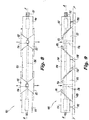
- Fig. 4 shows dual wedge assembly 102 as viewed toward mounting plane P.
- Each wedge surface 116 is oblique facing in a direction D that has a component 118 towards the mounting plane P, as indicated by the arrow in Fig. 6 , and a component 120 away from the longitudinal axis A in a direction parallel to the mounting plane P, as indicated by the two arrows in Fig. 5.
- Fig. 7 shows components 118 and 120 of direction D relative to mounting plane P and longitudinal axis A.
- component 120 can be further broken down into a component parallel to longitudinal axis A, and a component perpendicular to the direction of longitudinal axis A.
- a respective wedge surface of locking wedge 122 is engaged with each of the respective wedge surfaces 116 of the driver members 114 to be driven both toward the mounting plane P and lateral to the mounting plane P away from the longitudinal axis A by sliding along the respective wedge surfaces 116 of the driver members 114 with the actuator 112 driving the driver members 114 toward a centers of the locking wedges 122.
- the components 118 and 1 20 of direction D of wedge surfaces 116 allow driver members 114 to provide for this motion both away from axis A and toward mounting plane P.
- Figs. 2 and 3 show locking wedges 122 in the retracted position, in which a CCA 104 can be inserted into LRU 106, and Figs.
- FIG. 8 and 9 respectively, show the same views of dual wedge assembly 102, but with the locking wedges 122 in the extended position, as indicated by the large arrows in Figs. 8 and 9 , to lock CCA's in place within LRU 106.
- Fig. 8 shows how the locking wedges 122 move away from longitudinal axis A
- Fig. 9 shows how the locking wedges 122 also move towards mounting plane P, i.e., the centers of locking wedges 122 move closer to mounting plane P.
- a base member 124 is included opposite each of the driver members 114 across the respective locking wedges 122 along the longitudinal axis A.
- Base member 124 includes a pair of wedge surfaces 126 that are symmetrical with the wedge surfaces 116 of the respective driver members 114 across the center of the respective locking wedges 122.
- Each locking wedge 122 has a respective wedge surface that engages a respective wedge surface 126 of base member 124 to be driven outward from the longitudinal axis A and toward the mounting plane P as linear actuator 112 drives the respective driver member 114 toward base member 124.
- a chassis 128 of LRU 106 is included, along mounting plane P, wherein base member 124 is mounted to chassis 128 to be stationary relative to chassis 128, e.g. by pins 130, and wherein the driver members 114 are mounted to chassis 128 for longitudinal movement relative to the chassis 128, e.g., by sliding pins 132.
- Each respective set of driver members 114 and locking wedges 122 forms a clamping group, and each dual wedge assembly 102 includes a substantially symmetrical pair of clamping groups opposed to one another across the base member 124.
- Linear actuator 112 includes a threaded rod 134, wherein each driver member 114 is threaded to threaded rod 134 for linear actuation with rotary motion of the threaded rod 134.
- driver member 114 of a first one of the clamping groups as described above is threaded to the threaded rod 134 with threads in a first thread direction
- driver member 114 of the second clamping group as described above can be threaded to the threaded rod 134 with threads in a direction opposite the first thread direction for actuation of the driver members 114 in opposite axial directions.
- driver members 114 move towards each other and towards base member 124, as shown in Figs. 8 and 9 .
- Each locking wedge 122 is mounted back to back with another locking wedge 122 across the longitudinal axis A to be driven laterally to the mounting plane P away from its back to back mounting wedge 122.
- a biasing member 136 e.g. of a resilient material, is engaged to bias each back to back pair of locking wedges 122 together.
- Each locking wedge 122 can be driven into the extended position shown in Fig. 9 , where each locking wedge 122 is in thermal communication with the chassis 128 for conduction of heat through the respective locking wedge 122 to the chassis 128.
- the number of locking wedges 122 included, e.g., four locking wedges 122 as shown in Fig. 2 can be any suitable number without departing from the scope of this disclosure.
- a dual wedge assembly can include a single pair of back to back locking wedges 122, or three or more pairs of back to back locking wedges 122 as suitable for a given application, depending on the length of the dual wedge assembly.
- Those skilled in the art will also readily appreciate that it is possible to have single locking wedges instead of back to back locking wedges 122, where it is only desired to mount a single CCA 104 with a wedge assembly.
- each circuit card assembly 104 can be pinched between a respective set of locking wedges 122 and a shoulder portion 138 of chassis 128, so that the locking wedges 122 are in thermal communication with a base portion 140 of the chassis 128 for conduction of heat from the CCA's 104 through the locking wedges 122 to the chassis 128.
Landscapes
- Engineering & Computer Science (AREA)
- Microelectronics & Electronic Packaging (AREA)
- Manufacturing & Machinery (AREA)
- Cooling Or The Like Of Electrical Apparatus (AREA)
- Mounting Of Printed Circuit Boards And The Like (AREA)
- Connection Of Plates (AREA)
- Conveying Record Carriers (AREA)
- Die Bonding (AREA)
Claims (14)
- Vorrichtung (100) zum Montieren von Leiterplattenbaugruppen, umfassend:einen linearen Aktuator (112), der eine Längsachse (A) definiert;ein gegenüberliegendes Paar an Treiberelementen, wobei jedes Treiberelement (114) für Bewegung entlang der Längsachse (A) mit dem linearen Aktuator (112) in Eingriff genommen ist, wobei das Treiberelement (114) eine Montageebene (P) definiert und ein Paar an Keilflächen (116) beinhaltet, die schräg sind, wobei jede in eine Richtung zeigt, die eine Komponente (118) in eine erste Richtung zu der Montageebene (P) und eine Komponente weg von der Längsachse (A) in eine zweite Richtung parallel zu der Montageebene (P) aufweist, wobei sich die erste und die zweite Richtung voneinander unterscheiden;ein Paar an Rücken-an-Rücken-Verriegelungskeilen, wobei jeder Verriegelungskeil (122) mit einer der Keilflächen (116) eines jeweiligen Treiberelements (114) in Eingriff genommen ist, um sowohl zu der Montageebene (P) als auch zu dem Gehäuse (122) für Wärmekommunikation und seitlich zu der Montageebene (P) weg von der Längsachse (A) und zu der Leiterplatte zur Montage durch Verschieben entlang der Keilfläche (116) des Treiberelements (114) getrieben zu werden, wobei der Aktuator (112) das Treiberelement (114) zu einer Mitte des Verriegelungskeils (122) treibt; undein Vorspannelement (136), das konfiguriert ist, um das Paar an Rücken-an-Rücken-Verriegelungskeilen zusammen vorzuspannen.
- Vorrichtung (100) nach Anspruch 1, wobei
sich das Basiselement (124) gegenüber den Treiberelementen (114) quer über den Verriegelungskeil (122) entlang der Längsachse (A) befindet, wobei das Basiselement (124) eine Keilfläche (126) symmetrisch zu der Keilfläche (116) des Treiberelements (114) quer über die Mitte des Verriegelungskeils (122) beinhaltet, wobei der Verriegelungskeil (122) die Keilfläche (126) des Basiselements (124) in Eingriff nimmt, um von der Längsachse (A) nach außen und zu der Montageebene (P) getrieben zu werden, während der lineare Aktuator (112) das Treiberelement (114) zu dem Basiselement (124) treibt. - Vorrichtung nach Anspruch 2, wobei das Treiberelement (114) für Längsbewegung relativ zu dem Gehäuse (128) montiert ist.
- Vorrichtung nach einem der Ansprüche 1-3, wobei die Keilfläche (116) jedes Treiberelements (114) eine erste Keilfläche ist, wobei das Treiberelement (114) eine zweite Keilfläche symmetrisch zu der ersten Keilfläche quer über die Längsachse aufweist, wobei der zweite Verriegelungskeil mit der zweiten Keilfläche des Treiberelements in Eingriff genommen ist, um sowohl zu der Montageebene als auch seitlich zu der Montageebene weg von dem ersten Montagekeil getrieben zu werden.
- Vorrichtung nach Anspruch 4,
wobei sich das Basiselement (124) gegenüber dem Treiberelement (114) quer über die Verriegelungskeile entlang der Längsachse befindet, wobei das Basiselement (124) eine jeweilige erste und zweite Keilfläche symmetrisch zu den Keilflächen des Treiberelements (114) quer über die Mitte des Verriegelungskeils beinhaltet, wobei der erste und der zweite Verriegelungskeil die Keilflächen des Basiselements in Eingriff nehmen, um von der Längsachse nach außen und zu der Montageebene getrieben zu werden, während der lineare Aktuator das Treiberelement zu dem Basiselement treibt. - Vorrichtung nach Anspruch 6, wobei eines von den Treiberelementen (114) und seinen jeweiligen Verriegelungskeilen eine erste Klemmgruppe sind, die mit dem Basiselement (124) in Eingriff genommen ist, und das andere Treiberelement und seine jeweiligen Verriegelungskeile eine zweite Klemmgruppe sind, die mit dem Basiselement in Eingriff genommen ist, wobei die zweite Klemmgruppe im Wesentlichen symmetrisch zu der ersten Klemmgruppe quer über das Basiselement (124) ist.
- Vorrichtung nach Anspruch 1, wobei jeder Verriegelungskeil zur Betätigung zwischen einer eingezogenen Position nahe der Längsachse (A) und einer erweiterten Position beabstandet von der Längsachse und nahe der Montageebene mit dem Treiberelement (114) wirkverbunden ist.
- Vorrichtung nach Anspruch 3, wobei jeder Verriegelungskeil zur Betätigung zwischen einer eingezogenen Position nahe der Längsachse, beabstandet von dem Gehäuse, und einer erweiterten Position beabstandet von der Längsachse und in Wärmekommunikation mit dem Gehäuse zur Leitung von Wärme durch den Verriegelungskeil zu dem Gehäuse mit dem Treiberelement (114) wirkverbunden ist.
- Vorrichtung nach Anspruch 1, wobei der lineare Aktuator (112) eine Gewindestange beinhaltet, wobei jedes Treiberelement zur linearen Betätigung mit Drehbewegung der Gewindestange an die Gewindestange gewunden ist.
- Vorrichtung nach Anspruch 6, wobei der lineare Aktuator (112) eine Gewindestange beinhaltet, wobei das Treiberelement (114) der ersten Klemmgruppe mit Gewinden in eine erste Gewinderichtung an die Gewindestange gewunden ist und wobei das Treiberelement der zweiten Klemmgruppe mit Gewinden in eine Richtung entgegengesetzt zu der ersten Gewinderichtung zur Betätigung der Treiberelemente in entgegengesetzte axiale Richtungen an die Gewindestange gewunden ist.
- Vorrichtung nach Anspruch 3, ferner umfassend eine Leiterplattenbaugruppe (104), die zwischen den Verriegelungskeil und einen Schulterabschnitt des Gehäuses (128) geklemmt ist, wobei der Verriegelungskeil in Wärmekommunikation mit einem Basisabschnitt des Gehäuses zur Leitung von Wärme von der Leiterplattenbaugruppe durch den Verriegelungskeil zu dem Gehäuse ist.
- Vorrichtung nach Anspruch 11, wobei der lineare Aktuator (112), die Treiberelemente (114), die Verriegelungskeile (122) und das Basiselement (124) eine erste duale Keilbaugruppe sind, und ferner umfassend eine zweite solche duale Keilbaugruppe, die an dem Gehäuse gegenüber der ersten dualen Keilbaugruppe quer über die Leiterplattenbaugruppe montiert ist, wobei die Leiterplattenbaugruppe zwischen einen Verriegelungskeil der zweiten dualen Keilbaugruppe und einen Schulterabschnitt des Gehäuses geklemmt ist und wobei der Verriegelungskeil der zweiten Leiterplattenbaugruppe in Wärmekommunikation mit einem Basisabschnitt des Gehäuses zur Leitung von Wärme von der Leiterplattenbaugruppe zu dem Gehäuse ist.
- Vorrichtung nach Anspruch 4, ferner umfassend eine erste und eine zweite Leiterplattenbaugruppe (104), wobei die erste Leiterplattenbaugruppe zwischen den ersten Verriegelungskeil und einen Schulterabschnitt des Gehäuses geklemmt ist, wobei die zweite Leiterplattenbaugruppe zwischen den zweiten Verriegelungskeil und einen Schulterabschnitt des Gehäuses geklemmt ist, wobei jeder von dem ersten und dem zweiten Verriegelungskeil in Wärmekommunikation mit einem Basisabschnitt des Gehäuses zur Leitung von Wärme von der jeweiligen Leiterplattenbaugruppe zu dem Gehäuse ist.
- Vorrichtung nach Anspruch 13, wobei der lineare Aktuator (112), die Treiberelemente (114), die Verriegelungskeile und das Basiselement (124) eine erste duale Keilbaugruppe sind, und ferner umfassend eine zweite solche duale Keilbaugruppe, die an dem Gehäuse gegenüber der ersten dualen Keilbaugruppe quer über die Leiterplattenbaugruppe montiert ist, wobei die Leiterplattenbaugruppen zwischen jeweilige Verriegelungskeile der zweiten dualen Keilbaugruppe und jeweilige Schulterabschnitte des Gehäuses (128) geklemmt sind und wobei die Verriegelungskeile der zweiten Leiterplattenbaugruppe in Wärmekommunikation mit einem Basisabschnitt des Gehäuses (128) zur Leitung von Wärme von den Leiterplattenbaugruppen zu dem Gehäuse sind.
Applications Claiming Priority (1)
| Application Number | Priority Date | Filing Date | Title |
|---|---|---|---|
| US14/829,068 US9814169B2 (en) | 2015-08-18 | 2015-08-18 | Mounting devices |
Publications (3)
| Publication Number | Publication Date |
|---|---|
| EP3133908A2 EP3133908A2 (de) | 2017-02-22 |
| EP3133908A3 EP3133908A3 (de) | 2017-04-19 |
| EP3133908B1 true EP3133908B1 (de) | 2020-07-15 |
Family
ID=56852074
Family Applications (1)
| Application Number | Title | Priority Date | Filing Date |
|---|---|---|---|
| EP16183994.9A Active EP3133908B1 (de) | 2015-08-18 | 2016-08-12 | Montagevorrichtungen |
Country Status (4)
| Country | Link |
|---|---|
| US (1) | US9814169B2 (de) |
| EP (1) | EP3133908B1 (de) |
| BR (1) | BR102016018883B1 (de) |
| CA (1) | CA2938416C (de) |
Families Citing this family (4)
| Publication number | Priority date | Publication date | Assignee | Title |
|---|---|---|---|---|
| DE102017127607A1 (de) * | 2017-11-22 | 2019-05-23 | Liebherr-Elektronik Gmbh | Fixierungsvorrichtung zur Fixierung ein oder mehrerer Leiterplatten an einer Gehäusewand |
| US11160184B2 (en) | 2019-10-08 | 2021-10-26 | Hamilton Sundstrand Corporation | Vehicle circuit card assembly |
| US11326983B2 (en) * | 2020-01-07 | 2022-05-10 | Hamilton Sundstrand Corporation | Circuit retainer systems |
| US12610490B2 (en) | 2024-02-12 | 2026-04-21 | Wavetherm Corporation | Wedge based circuit board retainer with dual end drivescrew |
Family Cites Families (14)
| Publication number | Priority date | Publication date | Assignee | Title |
|---|---|---|---|---|
| US3194467A (en) | 1962-01-30 | 1965-07-13 | Western Union Telegraph Co | Waveguide flanging system |
| DE1953363A1 (de) | 1968-06-06 | 1971-05-13 | Telefunken Patent | Plattenspanneinrichtung |
| US4354770A (en) | 1980-05-19 | 1982-10-19 | The United States Of America As Represented By The Secretary Of The Navy | Wedge assembly |
| US4480287A (en) * | 1982-12-27 | 1984-10-30 | Raytheon Company | Module retainer apparatus |
| US5224016A (en) | 1990-05-31 | 1993-06-29 | Calmark Corporation | Retainer for electronic modules |
| US5036428A (en) | 1990-06-29 | 1991-07-30 | Eg&G Birtcher, Inc. | Printed circuit board retainer assembly |
| US5211496A (en) | 1990-07-27 | 1993-05-18 | Kaiser Aerospace And Electronics Corporation | Double wedgelock clamp |
| US5290122A (en) * | 1992-11-30 | 1994-03-01 | Eg&G Birtcher, Inc. | Printed circuit board retainer |
| US6695524B2 (en) * | 2001-11-19 | 2004-02-24 | Robert James Monson | Mount locking plate |
| US6615997B2 (en) * | 2002-02-07 | 2003-09-09 | Raytheon Company | Wedgelock system |
| US7483271B2 (en) * | 2005-05-19 | 2009-01-27 | Bae Systems Information And Electronic Systems Integration Inc. | High density card retention device |
| US7322843B1 (en) | 2006-07-11 | 2008-01-29 | Harris Corporation | Cam activated circuit card clamp |
| US8045332B2 (en) | 2008-07-23 | 2011-10-25 | Harris Corporation | Multi-direction wedge clamp |
| US8559178B2 (en) | 2010-10-11 | 2013-10-15 | Lockheed Martin Corporation | Cardlock clamp |
-
2015
- 2015-08-18 US US14/829,068 patent/US9814169B2/en active Active
-
2016
- 2016-08-08 CA CA2938416A patent/CA2938416C/en active Active
- 2016-08-12 EP EP16183994.9A patent/EP3133908B1/de active Active
- 2016-08-16 BR BR102016018883-0A patent/BR102016018883B1/pt active IP Right Grant
Non-Patent Citations (1)
| Title |
|---|
| None * |
Also Published As
| Publication number | Publication date |
|---|---|
| EP3133908A3 (de) | 2017-04-19 |
| EP3133908A2 (de) | 2017-02-22 |
| US20170055382A1 (en) | 2017-02-23 |
| CA2938416C (en) | 2023-11-14 |
| BR102016018883B1 (pt) | 2023-03-14 |
| BR102016018883A2 (pt) | 2017-02-21 |
| US9814169B2 (en) | 2017-11-07 |
| CA2938416A1 (en) | 2017-02-18 |
Similar Documents
| Publication | Publication Date | Title |
|---|---|---|
| CA2938416C (en) | Mounting devices | |
| US8456846B2 (en) | Wedge based circuit board retainer | |
| US8045332B2 (en) | Multi-direction wedge clamp | |
| EP3582597B1 (de) | Systeme und verfahren zur verbesserung der thermischen grenzfläche zwischen kühlkörper und schiene | |
| US4994937A (en) | Hydraulic thermal clamp for electronic modules | |
| US9233474B2 (en) | Clamping apparatus | |
| EP3091823B1 (de) | Kabelverwaltungsanordnung | |
| US9839116B2 (en) | Circuit card assembly with thermal energy removal | |
| US3903576A (en) | Apparatus for extracting circuit cards from chassis | |
| US9564712B1 (en) | Connecting assembly for securing two expansion cards | |
| EP3014378B1 (de) | Hebeleinheit | |
| EP2991461A1 (de) | Leiterplatte und elektronische vorrichtung | |
| US7483271B2 (en) | High density card retention device | |
| US9802295B2 (en) | Clamping device | |
| US3759559A (en) | Universal extractor tool | |
| US9700972B2 (en) | Pressing device | |
| US20130050926A1 (en) | Mounting apparatus for expansion cards | |
| US20150076306A1 (en) | Positioning apparatus | |
| EP3718384B1 (de) | Tiefwassertauchsystem | |
| US9128680B2 (en) | Casing structure and electronic device using the same | |
| JP2014006956A (ja) | ハードディスクの固定装置 | |
| US20140313678A1 (en) | Mounting device for expansion card | |
| CN205819577U (zh) | 用于飞行器上的快速装卸装置及飞行器 | |
| US10195726B2 (en) | De-mating apparatus | |
| CN104747637A (zh) | 一种新型簧片锁紧条 |
Legal Events
| Date | Code | Title | Description |
|---|---|---|---|
| PUAI | Public reference made under article 153(3) epc to a published international application that has entered the european phase |
Free format text: ORIGINAL CODE: 0009012 |
|
| STAA | Information on the status of an ep patent application or granted ep patent |
Free format text: STATUS: THE APPLICATION HAS BEEN PUBLISHED |
|
| AK | Designated contracting states |
Kind code of ref document: A2 Designated state(s): AL AT BE BG CH CY CZ DE DK EE ES FI FR GB GR HR HU IE IS IT LI LT LU LV MC MK MT NL NO PL PT RO RS SE SI SK SM TR |
|
| AX | Request for extension of the european patent |
Extension state: BA ME |
|
| PUAL | Search report despatched |
Free format text: ORIGINAL CODE: 0009013 |
|
| AK | Designated contracting states |
Kind code of ref document: A3 Designated state(s): AL AT BE BG CH CY CZ DE DK EE ES FI FR GB GR HR HU IE IS IT LI LT LU LV MC MK MT NL NO PL PT RO RS SE SI SK SM TR |
|
| AX | Request for extension of the european patent |
Extension state: BA ME |
|
| RIC1 | Information provided on ipc code assigned before grant |
Ipc: H05K 13/04 20060101ALI20170315BHEP Ipc: H05K 7/14 20060101AFI20170315BHEP |
|
| STAA | Information on the status of an ep patent application or granted ep patent |
Free format text: STATUS: REQUEST FOR EXAMINATION WAS MADE |
|
| 17P | Request for examination filed |
Effective date: 20171018 |
|
| RBV | Designated contracting states (corrected) |
Designated state(s): AL AT BE BG CH CY CZ DE DK EE ES FI FR GB GR HR HU IE IS IT LI LT LU LV MC MK MT NL NO PL PT RO RS SE SI SK SM TR |
|
| STAA | Information on the status of an ep patent application or granted ep patent |
Free format text: STATUS: EXAMINATION IS IN PROGRESS |
|
| 17Q | First examination report despatched |
Effective date: 20180613 |
|
| GRAP | Despatch of communication of intention to grant a patent |
Free format text: ORIGINAL CODE: EPIDOSNIGR1 |
|
| STAA | Information on the status of an ep patent application or granted ep patent |
Free format text: STATUS: GRANT OF PATENT IS INTENDED |
|
| INTG | Intention to grant announced |
Effective date: 20200210 |
|
| GRAS | Grant fee paid |
Free format text: ORIGINAL CODE: EPIDOSNIGR3 |
|
| GRAA | (expected) grant |
Free format text: ORIGINAL CODE: 0009210 |
|
| STAA | Information on the status of an ep patent application or granted ep patent |
Free format text: STATUS: THE PATENT HAS BEEN GRANTED |
|
| AK | Designated contracting states |
Kind code of ref document: B1 Designated state(s): AL AT BE BG CH CY CZ DE DK EE ES FI FR GB GR HR HU IE IS IT LI LT LU LV MC MK MT NL NO PL PT RO RS SE SI SK SM TR |
|
| REG | Reference to a national code |
Ref country code: CH Ref legal event code: EP Ref country code: GB Ref legal event code: FG4D |
|
| REG | Reference to a national code |
Ref country code: IE Ref legal event code: FG4D |
|
| REG | Reference to a national code |
Ref country code: DE Ref legal event code: R096 Ref document number: 602016039862 Country of ref document: DE |
|
| REG | Reference to a national code |
Ref country code: AT Ref legal event code: REF Ref document number: 1292460 Country of ref document: AT Kind code of ref document: T Effective date: 20200815 |
|
| REG | Reference to a national code |
Ref country code: LT Ref legal event code: MG4D |
|
| REG | Reference to a national code |
Ref country code: AT Ref legal event code: MK05 Ref document number: 1292460 Country of ref document: AT Kind code of ref document: T Effective date: 20200715 |
|
| REG | Reference to a national code |
Ref country code: NL Ref legal event code: MP Effective date: 20200715 |
|
| PG25 | Lapsed in a contracting state [announced via postgrant information from national office to epo] |
Ref country code: PT Free format text: LAPSE BECAUSE OF FAILURE TO SUBMIT A TRANSLATION OF THE DESCRIPTION OR TO PAY THE FEE WITHIN THE PRESCRIBED TIME-LIMIT Effective date: 20201116 Ref country code: FI Free format text: LAPSE BECAUSE OF FAILURE TO SUBMIT A TRANSLATION OF THE DESCRIPTION OR TO PAY THE FEE WITHIN THE PRESCRIBED TIME-LIMIT Effective date: 20200715 Ref country code: LT Free format text: LAPSE BECAUSE OF FAILURE TO SUBMIT A TRANSLATION OF THE DESCRIPTION OR TO PAY THE FEE WITHIN THE PRESCRIBED TIME-LIMIT Effective date: 20200715 Ref country code: GR Free format text: LAPSE BECAUSE OF FAILURE TO SUBMIT A TRANSLATION OF THE DESCRIPTION OR TO PAY THE FEE WITHIN THE PRESCRIBED TIME-LIMIT Effective date: 20201016 Ref country code: BG Free format text: LAPSE BECAUSE OF FAILURE TO SUBMIT A TRANSLATION OF THE DESCRIPTION OR TO PAY THE FEE WITHIN THE PRESCRIBED TIME-LIMIT Effective date: 20201015 Ref country code: NO Free format text: LAPSE BECAUSE OF FAILURE TO SUBMIT A TRANSLATION OF THE DESCRIPTION OR TO PAY THE FEE WITHIN THE PRESCRIBED TIME-LIMIT Effective date: 20201015 Ref country code: AT Free format text: LAPSE BECAUSE OF FAILURE TO SUBMIT A TRANSLATION OF THE DESCRIPTION OR TO PAY THE FEE WITHIN THE PRESCRIBED TIME-LIMIT Effective date: 20200715 Ref country code: ES Free format text: LAPSE BECAUSE OF FAILURE TO SUBMIT A TRANSLATION OF THE DESCRIPTION OR TO PAY THE FEE WITHIN THE PRESCRIBED TIME-LIMIT Effective date: 20200715 Ref country code: SE Free format text: LAPSE BECAUSE OF FAILURE TO SUBMIT A TRANSLATION OF THE DESCRIPTION OR TO PAY THE FEE WITHIN THE PRESCRIBED TIME-LIMIT Effective date: 20200715 Ref country code: HR Free format text: LAPSE BECAUSE OF FAILURE TO SUBMIT A TRANSLATION OF THE DESCRIPTION OR TO PAY THE FEE WITHIN THE PRESCRIBED TIME-LIMIT Effective date: 20200715 |
|
| PG25 | Lapsed in a contracting state [announced via postgrant information from national office to epo] |
Ref country code: RS Free format text: LAPSE BECAUSE OF FAILURE TO SUBMIT A TRANSLATION OF THE DESCRIPTION OR TO PAY THE FEE WITHIN THE PRESCRIBED TIME-LIMIT Effective date: 20200715 Ref country code: PL Free format text: LAPSE BECAUSE OF FAILURE TO SUBMIT A TRANSLATION OF THE DESCRIPTION OR TO PAY THE FEE WITHIN THE PRESCRIBED TIME-LIMIT Effective date: 20200715 Ref country code: LV Free format text: LAPSE BECAUSE OF FAILURE TO SUBMIT A TRANSLATION OF THE DESCRIPTION OR TO PAY THE FEE WITHIN THE PRESCRIBED TIME-LIMIT Effective date: 20200715 Ref country code: IS Free format text: LAPSE BECAUSE OF FAILURE TO SUBMIT A TRANSLATION OF THE DESCRIPTION OR TO PAY THE FEE WITHIN THE PRESCRIBED TIME-LIMIT Effective date: 20201115 |
|
| PG25 | Lapsed in a contracting state [announced via postgrant information from national office to epo] |
Ref country code: NL Free format text: LAPSE BECAUSE OF FAILURE TO SUBMIT A TRANSLATION OF THE DESCRIPTION OR TO PAY THE FEE WITHIN THE PRESCRIBED TIME-LIMIT Effective date: 20200715 |
|
| REG | Reference to a national code |
Ref country code: CH Ref legal event code: PL |
|
| REG | Reference to a national code |
Ref country code: DE Ref legal event code: R097 Ref document number: 602016039862 Country of ref document: DE |
|
| PG25 | Lapsed in a contracting state [announced via postgrant information from national office to epo] |
Ref country code: LI Free format text: LAPSE BECAUSE OF NON-PAYMENT OF DUE FEES Effective date: 20200831 Ref country code: MC Free format text: LAPSE BECAUSE OF FAILURE TO SUBMIT A TRANSLATION OF THE DESCRIPTION OR TO PAY THE FEE WITHIN THE PRESCRIBED TIME-LIMIT Effective date: 20200715 Ref country code: LU Free format text: LAPSE BECAUSE OF NON-PAYMENT OF DUE FEES Effective date: 20200812 Ref country code: CZ Free format text: LAPSE BECAUSE OF FAILURE TO SUBMIT A TRANSLATION OF THE DESCRIPTION OR TO PAY THE FEE WITHIN THE PRESCRIBED TIME-LIMIT Effective date: 20200715 Ref country code: CH Free format text: LAPSE BECAUSE OF NON-PAYMENT OF DUE FEES Effective date: 20200831 Ref country code: DK Free format text: LAPSE BECAUSE OF FAILURE TO SUBMIT A TRANSLATION OF THE DESCRIPTION OR TO PAY THE FEE WITHIN THE PRESCRIBED TIME-LIMIT Effective date: 20200715 Ref country code: RO Free format text: LAPSE BECAUSE OF FAILURE TO SUBMIT A TRANSLATION OF THE DESCRIPTION OR TO PAY THE FEE WITHIN THE PRESCRIBED TIME-LIMIT Effective date: 20200715 Ref country code: SM Free format text: LAPSE BECAUSE OF FAILURE TO SUBMIT A TRANSLATION OF THE DESCRIPTION OR TO PAY THE FEE WITHIN THE PRESCRIBED TIME-LIMIT Effective date: 20200715 Ref country code: EE Free format text: LAPSE BECAUSE OF FAILURE TO SUBMIT A TRANSLATION OF THE DESCRIPTION OR TO PAY THE FEE WITHIN THE PRESCRIBED TIME-LIMIT Effective date: 20200715 Ref country code: IT Free format text: LAPSE BECAUSE OF FAILURE TO SUBMIT A TRANSLATION OF THE DESCRIPTION OR TO PAY THE FEE WITHIN THE PRESCRIBED TIME-LIMIT Effective date: 20200715 |
|
| PLBE | No opposition filed within time limit |
Free format text: ORIGINAL CODE: 0009261 |
|
| STAA | Information on the status of an ep patent application or granted ep patent |
Free format text: STATUS: NO OPPOSITION FILED WITHIN TIME LIMIT |
|
| REG | Reference to a national code |
Ref country code: BE Ref legal event code: MM Effective date: 20200831 |
|
| PG25 | Lapsed in a contracting state [announced via postgrant information from national office to epo] |
Ref country code: AL Free format text: LAPSE BECAUSE OF FAILURE TO SUBMIT A TRANSLATION OF THE DESCRIPTION OR TO PAY THE FEE WITHIN THE PRESCRIBED TIME-LIMIT Effective date: 20200715 |
|
| 26N | No opposition filed |
Effective date: 20210416 |
|
| PG25 | Lapsed in a contracting state [announced via postgrant information from national office to epo] |
Ref country code: SK Free format text: LAPSE BECAUSE OF FAILURE TO SUBMIT A TRANSLATION OF THE DESCRIPTION OR TO PAY THE FEE WITHIN THE PRESCRIBED TIME-LIMIT Effective date: 20200715 |
|
| PG25 | Lapsed in a contracting state [announced via postgrant information from national office to epo] |
Ref country code: BE Free format text: LAPSE BECAUSE OF NON-PAYMENT OF DUE FEES Effective date: 20200831 Ref country code: SI Free format text: LAPSE BECAUSE OF FAILURE TO SUBMIT A TRANSLATION OF THE DESCRIPTION OR TO PAY THE FEE WITHIN THE PRESCRIBED TIME-LIMIT Effective date: 20200715 Ref country code: IE Free format text: LAPSE BECAUSE OF NON-PAYMENT OF DUE FEES Effective date: 20200812 |
|
| PG25 | Lapsed in a contracting state [announced via postgrant information from national office to epo] |
Ref country code: TR Free format text: LAPSE BECAUSE OF FAILURE TO SUBMIT A TRANSLATION OF THE DESCRIPTION OR TO PAY THE FEE WITHIN THE PRESCRIBED TIME-LIMIT Effective date: 20200715 Ref country code: MT Free format text: LAPSE BECAUSE OF FAILURE TO SUBMIT A TRANSLATION OF THE DESCRIPTION OR TO PAY THE FEE WITHIN THE PRESCRIBED TIME-LIMIT Effective date: 20200715 Ref country code: CY Free format text: LAPSE BECAUSE OF FAILURE TO SUBMIT A TRANSLATION OF THE DESCRIPTION OR TO PAY THE FEE WITHIN THE PRESCRIBED TIME-LIMIT Effective date: 20200715 |
|
| PG25 | Lapsed in a contracting state [announced via postgrant information from national office to epo] |
Ref country code: MK Free format text: LAPSE BECAUSE OF FAILURE TO SUBMIT A TRANSLATION OF THE DESCRIPTION OR TO PAY THE FEE WITHIN THE PRESCRIBED TIME-LIMIT Effective date: 20200715 |
|
| REG | Reference to a national code |
Ref country code: DE Ref legal event code: R081 Ref document number: 602016039862 Country of ref document: DE Owner name: SIMMONDS PRECISION PRODUCTS, INC. (N.D.GES.D. , US Free format text: FORMER OWNER: HAMILTON SUNDSTRAND CORPORATION, CHARLOTTE, N.C., US |
|
| PGFP | Annual fee paid to national office [announced via postgrant information from national office to epo] |
Ref country code: DE Payment date: 20250724 Year of fee payment: 10 |
|
| PGFP | Annual fee paid to national office [announced via postgrant information from national office to epo] |
Ref country code: GB Payment date: 20250725 Year of fee payment: 10 |
|
| PGFP | Annual fee paid to national office [announced via postgrant information from national office to epo] |
Ref country code: FR Payment date: 20250723 Year of fee payment: 10 |
|
| REG | Reference to a national code |
Ref country code: GB Ref legal event code: 732E Free format text: REGISTERED BETWEEN 20251002 AND 20251008 |