EP3133786B1 - Optical transmission system and transmission method, optical switching device and control method - Google Patents
Optical transmission system and transmission method, optical switching device and control method Download PDFInfo
- Publication number
- EP3133786B1 EP3133786B1 EP14889759.8A EP14889759A EP3133786B1 EP 3133786 B1 EP3133786 B1 EP 3133786B1 EP 14889759 A EP14889759 A EP 14889759A EP 3133786 B1 EP3133786 B1 EP 3133786B1
- Authority
- EP
- European Patent Office
- Prior art keywords
- optical
- output port
- switching
- signal
- port address
- Prior art date
- Legal status (The legal status is an assumption and is not a legal conclusion. Google has not performed a legal analysis and makes no representation as to the accuracy of the status listed.)
- Not-in-force
Links
Images




Classifications
-
- H—ELECTRICITY
- H04—ELECTRIC COMMUNICATION TECHNIQUE
- H04Q—SELECTING
- H04Q11/00—Selecting arrangements for multiplex systems
- H04Q11/0001—Selecting arrangements for multiplex systems using optical switching
- H04Q11/0062—Network aspects
- H04Q11/0066—Provisions for optical burst or packet networks
-
- H—ELECTRICITY
- H04—ELECTRIC COMMUNICATION TECHNIQUE
- H04L—TRANSMISSION OF DIGITAL INFORMATION, e.g. TELEGRAPHIC COMMUNICATION
- H04L12/00—Data switching networks
- H04L12/02—Details
- H04L12/16—Arrangements for providing special services to substations
- H04L12/18—Arrangements for providing special services to substations for broadcast or conference, e.g. multicast
-
- H—ELECTRICITY
- H04—ELECTRIC COMMUNICATION TECHNIQUE
- H04L—TRANSMISSION OF DIGITAL INFORMATION, e.g. TELEGRAPHIC COMMUNICATION
- H04L45/00—Routing or path finding of packets in data switching networks
- H04L45/50—Routing or path finding of packets in data switching networks using label swapping, e.g. multi-protocol label switch [MPLS]
-
- H—ELECTRICITY
- H04—ELECTRIC COMMUNICATION TECHNIQUE
- H04Q—SELECTING
- H04Q11/00—Selecting arrangements for multiplex systems
- H04Q11/0001—Selecting arrangements for multiplex systems using optical switching
- H04Q11/0005—Switch and router aspects
-
- H—ELECTRICITY
- H04—ELECTRIC COMMUNICATION TECHNIQUE
- H04Q—SELECTING
- H04Q11/00—Selecting arrangements for multiplex systems
- H04Q11/0001—Selecting arrangements for multiplex systems using optical switching
- H04Q11/0062—Network aspects
-
- H—ELECTRICITY
- H04—ELECTRIC COMMUNICATION TECHNIQUE
- H04Q—SELECTING
- H04Q11/00—Selecting arrangements for multiplex systems
- H04Q11/0001—Selecting arrangements for multiplex systems using optical switching
- H04Q11/0005—Switch and router aspects
- H04Q2011/0037—Operation
- H04Q2011/0039—Electrical control
-
- H—ELECTRICITY
- H04—ELECTRIC COMMUNICATION TECHNIQUE
- H04Q—SELECTING
- H04Q11/00—Selecting arrangements for multiplex systems
- H04Q11/0001—Selecting arrangements for multiplex systems using optical switching
- H04Q11/0005—Switch and router aspects
- H04Q2011/0037—Operation
- H04Q2011/005—Arbitration and scheduling
-
- H—ELECTRICITY
- H04—ELECTRIC COMMUNICATION TECHNIQUE
- H04Q—SELECTING
- H04Q11/00—Selecting arrangements for multiplex systems
- H04Q11/0001—Selecting arrangements for multiplex systems using optical switching
- H04Q11/0005—Switch and router aspects
- H04Q2011/0052—Interconnection of switches
- H04Q2011/0058—Crossbar; Matrix
-
- H—ELECTRICITY
- H04—ELECTRIC COMMUNICATION TECHNIQUE
- H04Q—SELECTING
- H04Q11/00—Selecting arrangements for multiplex systems
- H04Q11/0001—Selecting arrangements for multiplex systems using optical switching
- H04Q11/0062—Network aspects
- H04Q2011/0077—Labelling aspects, e.g. multiprotocol label switching [MPLS], G-MPLS, MPAS
Definitions
- the present invention relates to the field of communications technologies, and in particular, to an optical transmission system and transmission method, an optical switching apparatus, and a control method.
- an optical switching system usually uses a burst-mode transmission mechanism to transmit an optical signal, that is, there is a spacing between data packets carried in the optical signal. Therefore, a burst signal is generated.
- FIG. 1A shows a burst signal. Because amplitudes between burst signals differ greatly, when receiving optical signals, an optical receiving system needs to adjust a parameter such as a gain proportion according to a power peak value of each optical signal, so that the optical signals of different strengths are converted into electrical signals of a same strength, thereby ensuring that the optical receiving system can receive the optical signals successfully.
- an Ethernet data frame length ranges from 64B to 1510B.
- a shortest packet requires 50 ns, and if a preamble that requires tens of nanoseconds is added, a waste of about 50% bandwidth is caused.
- WO 2005/043843 A1 discloses an architecture and method for performing dynamic route discovery and variable time slot reservation provisioning within optical-switched networks. The method employs extensions to the RSVP-TE signaling protocol, which uses various messages to reserve network resources. Under an overlay routing embodiment, network resources are reserved via a resource reservation message that is sent hop-by-hop between switching nodes, wherein the next hops are dynamically selected based on routing tree tables in the switching nodes. The concatenation of hops forms the route for the reserved lightpath. The resource reservation request is passed between nodes defined by a dynamically routed path, and resource availability is confirmed for the entire lightpath prior to confirming the resource reservations
- US 2003/198471 A1 discloses an intelligent optical burst switching module for use in an optical switching network includes an optical receiver array, optical transmitter array, a core switch unit and a control unit.
- the core switch unit routes optical control and data signals received via a plurality of optical input lines to the optical receiver array and a plurality of output lines, respectively.
- the optical output lines provide propagation paths for a plurality of TDM channels.
- WO 03/050708 A1 relates to a method and a system for transmitting information via Fibre Channel standard.
- Information is transformed between two link partners (10,20) as Sequence Ordered Sets or Signal Ordered Sets in XGMII or Fibre Channel (18).
- Such sets are defined to not be amended by intervening PHY's and may be transmitted even when there is no other traffic between the link partners
- CN 103 609 083 A1 provides a receiving device and an optical switching fabric apparatus.
- the receiving device comprises a plurality of selection modules, quick optical switches respectively connected to the selection modules, an output module connected with all the quick optical switches, and a receiver connected with the output module, wherein the selection module is used for receiving a multi-wave optical signal, and selecting and filtering a first optical signal within a preset time period in the multi-wave optical signal.
- Embodiments of the present invention provide an optical transmission system and transmission method, a switching apparatus, and a control method, so as to overcome a prior-art disadvantage of resource waste.
- an optical transmission system including an optical switching apparatus, at least one optical packet transmission apparatus configured to transmit a continuous data signal comprising an idle sequence and a data packet, and at least one optical label transmission apparatus configured to transmit an optical label signal, and transmit the optical label signal to an optical switching apparatus, where the optical switching apparatus is configured to build, according to the optical label signal, a switching and transmission path for transmitting a continuous data signal transmitted by a corresponding optical packet transmission apparatus, where any optical label carried in the optical label signal corresponds to one data packet in the corresponding data signal, and switching and transmission paths corresponding to data signals transmitted by the any two different optical packet transmission apparatuses have different output ports.
- any optical packet transmission apparatus includes a data packet transmission module and an idle sequence transmission module, where the data packet transmission module is configured to transmit a data packet; and the idle sequence transmission module is configured to transmit an idle sequence between any two adjacent data packets.
- the optical label transmission apparatus is further configured to: generate an optical label, where any optical label includes a preset switching destination output port address, a data length, and an optical label identifier.
- the optical switching apparatus includes a management and control module and an optical switch matrix
- the management and control module is configured to: receive an optical label signal transmitted by an optical transmission system, and transmit, to the optical switch matrix, a control signal generated according to the optical label signal
- the optical switch matrix is configured to: receive a continuous data signal transmitted by the optical transmission system and the control signal; adjust, according to the control signal, an optical switch unit on a link between each input port for data signal input and a corresponding output port for data signal output, to build a switching and transmission path for transmitting the continuous data signal; and input the any data signal to an optical receiving system through the switching and transmission path, where any two different switching and transmission paths have different input ports and output ports.
- each optical label carried in the optical label signal received by the management and control module includes a preset switching destination output port address, a data length, and an optical label identifier.
- management and control module is specifically configured to:
- management and control module is further configured to:
- the optical switch matrix is specifically configured to: perform the following operations separately with respect to a control signal corresponding to any data signal:
- management and control module is specifically configured to:
- the determining, by the management and control module, whether the any data packet meets a preset condition is specifically: determining whether the optical label corresponding to the data packet is correct and/or whether the corresponding preset switching destination output port address is occupied.
- the management and control module is specifically configured to: use, with respect to an idle sequence, the any switching output port in the determined idle switching output port as an actual switching destination output port address of the idle sequence, and generate a control signal according to the actual switching destination output port address.
- management and control module is specifically configured to:
- management and control module is further configured to:
- the optical switching apparatus further includes the power equilibrium unit, configured to perform power compensation before a data packet is input to the optical receiving system through a corresponding actual switching destination output port.
- a control method including:
- the generating a control signal according to the optical label signal specifically includes:
- the generating a control signal according to the optical label signal specifically includes:
- the method further includes:
- an optical signal transmitted by an optical transmission system is a burst data signal.
- a common practice of processing a burst signal by an optical receiving system is: adding a preamble before a data packet carried in each optical signal, to adjust a status of an optical receiver; however, a disadvantage of resource waste exists.
- An optical transmission system provided in the embodiments of the present invention includes at least one data transmission apparatus.
- Any data transmission apparatus is configured to: transmit an optical label signal and a continuous data signal including an idle sequence and a data packet, and transmit the transmitted optical label signal to an optical switching apparatus, so that the optical switching apparatus builds, according to the optical label signal, a switching and transmission path for transmitting the continuous data signal transmitted by the any data transmission apparatus, where any optical label carried in the optical label signal corresponds to one data packet in the data signal, and switching and transmission paths corresponding to data signals transmitted by any two different data transmission apparatuses have different output ports.
- This ensures that a data transmission apparatus transmits a continuous data signal, and also ensures that each optical receiving system can receive the continuous data signal. Therefore, no preamble needs to be added before a data packet carried in a to-be-processed data signal, thereby avoiding a resource waste.
- the optical transmission system includes at least one data transmission apparatus, where any data transmission apparatus is configured to: transmit an optical label signal and a continuous data signal including an idle sequence and a data packet, and transmit the transmitted optical label signal to an optical switching apparatus, so that the optical switching apparatus builds, according to the optical label signal, a switching and transmission path for transmitting the continuous data signal transmitted by the any data transmission apparatus, where any optical label carried in the optical label signal corresponds to one data packet in the data signal, and switching and transmission paths corresponding to data signals transmitted by any two different data transmission apparatuses have different output ports.
- This ensures that a data transmission apparatus transmits a continuous data signal, and also ensures that each optical receiving system can receive the continuous data signal. Therefore, no preamble needs to be added before a data packet carried in a to-be-processed data signal, thereby avoiding a resource waste.
- this embodiment of the present invention provides an optical transmission system 200, where the optical transmission system 200 includes at least one data transmission apparatus 1.
- Any data transmission apparatus 1 is configured to: transmit an optical label signal and a continuous data signal including an idle sequence and a data packet, and transmit the transmitted optical label signal to an optical switching apparatus 2, so that the optical switching apparatus 2 builds, according to the optical label signal, a switching and transmission path for transmitting the continuous data signal transmitted by the any data transmission apparatus 1.
- Any optical label carried in the optical label signal corresponds to one data packet in the data signal, and switching and transmission paths corresponding to data signals transmitted by any two different data transmission apparatuses 1 have different output ports.
- the optical label signal and the data signal are transmitted in multiple manners.
- an in-band transmission mechanism may be used for transmission (that is, the optical label signal and the data signal may be transmitted through a same channel).
- an idle sequence is filled in between an optical label and a data packet to ensure data signal continuity. This transmission manner is used in Embodiment 2.
- each optical label corresponds to one piece of data.
- an optical label 1 corresponds to a data packet 1
- an optical label 2 corresponds to a data packet 2
- an optical label 3 corresponds to a data packet 3, regardless of whether an in-band transmission mechanism or an out-of-band transmission mechanism is used.
- the optical label signal is used by the optical switching apparatus 2 to build the switching and transmission path for transmitting the continuous data signal transmitted by the any data transmission apparatus 1, that is, a specific delay exists between a time of receiving an optical label by a management and control module 21 and a time of generating a control signal to drive an optical switch matrix 22 to complete building of the switching and transmission path. Therefore, optionally, each optical label needs to be transmitted earlier than a corresponding data packet. In this way, before a data packet arrives at the optical switch matrix 22, the management and control module 21 has generated a control signal according to a corresponding optical label, and then the optical switch matrix 22 builds, according to the control signal, a switching and transmission path for data signal transmission.
- an optical label may be transmitted together with a corresponding data packet, or a corresponding data packet is transmitted earlier than an optical label; in this case, delay control needs to be performed on the data packet, and the data packet is transmitted after the management and control module 21 generates a control signal according to the optical label and builds a transmission path.
- any data transmission apparatus 1 includes an optical label transmission module 11, a data packet transmission module 12, and an idle sequence transmission module 13.
- the optical label transmission module 11 is configured to transmit an optical label.
- the data packet transmission module 12 is configured to transmit a data packet.
- the idle sequence transmission module 13 is configured to transmit an idle sequence between any optical label and any data packet that are adjacent.
- the optical label transmission module 11 is further configured to: generate an optical label, where any optical label includes a preset switching destination output port address, a data length, and an optical label identifier. That is, FIG. 2D shows a form of an optical label.
- the preset switching destination output port address in the optical label is used to build a switching and transmission path.
- the data length is used to calculate duration (that is, a validity time) of a control signal, to ensure completion of data signal transmission and switching.
- a function of the optical label identifier is to identify a start of an optical label signal in the management and control module 21 by using the optical label identifier.
- FIG. 2E is a schematic diagram of a data transmission apparatus 1 in an in-band transmission manner.
- a transmission process of the data transmission apparatus 1 is described by using two-layer Ethernet optical packet switching as an example.
- a data frame is stored in an Ethernet optical packet storage module before being transmitted.
- a destination MAC (Medium Access Control; media access control) address needs to be read from the data frame, where the destination MAC address is used to determine a preset switching destination output port address; a data frame length is read from the data frame, where the data frame length is used to determine a data length; then, an optical label is generated according to the preset switching destination output port address, the data length, and an optical label identifier.
- a destination MAC Medium Access Control; media access control
- the management and control module 21 can obtain, by searching a table, a preset switching destination output port address corresponding to a destination port number.
- Table 1 shows a correspondence between a destination MAC address and a preset switching destination output port address, where each preset switching destination output port address corresponds to multiple MAC addresses.
- the data transmission apparatus 1 included in the optical transmission system provided in Embodiment 1 transmits both the optical label signal and the data signal.
- the optical label signal and the data signal may be transmitted by different devices, or may be transmitted by using an out-of-band transmission mechanism (that is, the optical label signal and the data signal may be transmitted through different channels).
- an out-of-band transmission mechanism that is, the optical label signal and the data signal may be transmitted through different channels.
- an idle sequence is transmitted when no data is transmitted through a data signal transmission channel.
- an idle sequence or no idle sequence may be transmitted between optical label signals, as shown in Embodiment 2.
- this embodiment of the present invention provides an optical transmission system 200, where the optical transmission system 200 includes at least one optical packet transmission apparatus 1 / and at least one optical label transmission apparatus 2 / .
- Any optical packet transmission apparatus 1 / is configured to transmit a continuous data signal including idle information and a data packet.
- Any optical label transmission apparatus 2 / is configured to: transmit an optical label signal, and transmit the optical label signal to an optical switching apparatus 2, so that the optical switching apparatus 2 builds, according to the optical label signal, a switching and transmission path for transmitting a continuous data signal transmitted by a corresponding optical packet transmission apparatus 1 / .
- Any optical label carried in the optical label signal corresponds to one data packet in the corresponding data signal, and switching and transmission paths corresponding to data signals transmitted by any two different optical packet transmission apparatuses 1 / have different output ports.
- any optical packet transmission apparatus 1 / includes a data packet transmission module 11 / and an idle sequence transmission module 12 / .
- the data packet transmission module 11 / is configured to transmit a data packet.
- the idle sequence transmission module 12 / is configured to transmit an idle sequence between any two adjacent data packets.
- the optical label transmission module 2 / is further configured to: generate an optical label, where any optical label includes a preset switching destination output port address, a data length, and an optical label identifier.
- this embodiment of the present invention further provides an optical switching apparatus 2, including a management and control module 21 and an optical switch matrix 22.
- the management and control module 21 is configured to: receive an optical label signal transmitted by an optical transmission system 200, and transmit, to the optical switch matrix 22, a control signal generated according to the optical label signal.
- the optical switch matrix 22 is configured to: receive a continuous data signal transmitted by the optical transmission system 200 and the control signal; adjust, according to the control signal, an optical switch unit on a link between each input port for data signal input and a corresponding output port for data signal output, to build a switching and transmission path for transmitting the continuous data signal; and input any data signal to an optical receiving system 500 through the switching and transmission path.
- the management and control module 21 determines a location of an optical label by using an optical label identifier, then extracts a preset switching destination output port address from the optical label to generate an actual switching destination output port address, and extracts data length information to generate duration of the control signal.
- FIG. 4B shows a processing process of generating a control signal by the optical switching apparatus 2.
- each optical label carried in the optical label signal received by the management and control module 21 includes a preset switching destination output port address, a data length, and an optical label identifier.
- the management and control module 21 is specifically configured to:
- management and control module 21 is further configured to:
- Step a Set, to m, a preset switching destination output port port_num_1 corresponding to a preset switching destination output port address.
- step b whether a bit error occurs on an optical label is first determined, and if the error occurs, an unoccupied output port is used as an actual switching destination output port for a data packet corresponding to the optical label, or if no error occurs, step b is performed.
- Step b Determine a status path_state of the preset switching destination output port m; and if the path state is 1, perform step c; otherwise, perform step d.
- Step c If the path state is 1, which indicates that the preset switching destination output port m is occupied, set the port_num_1 to 0.
- Step d If the path state is 0, which indicates that the preset switching destination output port m is unoccupied, set the path state of the preset switching destination output port m to 1.
- an actual switching destination output port address of a data signal corresponding to a preset switching destination output port address is the preset switching destination output port address; an input port is connected to an actual switching destination output port, so as to build a switching and transmission path. That is, the corresponding data signal is input to the optical receiving system 500 through the preset switching destination output port.
- Step e A counter build_time starts counting when a switching and transmission path starts to be built; when a numerical value on the counter build time is equal to duration of a control signal, which indicates that a validity time of the switching and transmission path expires, set both the port_num_1 and the path state of the output port m to 0, and release the link.
- an actual switching destination output port address corresponding to each data signal is determined, and after the actual switching destination output port address corresponding to each data signal is determined, a corresponding control signal can be generated by searching a table.
- Table 2 shows a correspondence between a control signal and an actual switching destination output port address by using a control signal for a 4x4 banyan optical switch matrix 22.
- the actual switching destination output port address may be not stored.
- the optical switch matrix 22 is specifically configured to: perform the following operations separately with respect to a control signal corresponding to any data signal:
- the management and control module 21 is specifically configured to:
- the determining, by the management and control module 21, whether the any data packet meets a preset condition is specifically: determining whether the optical label corresponding to the data packet is correct and/or whether the corresponding preset switching destination output port address is occupied.
- the management and control module 21 is specifically configured to: use, with respect to an idle sequence, the any switching output port in the determined idle switching output port as an actual switching destination output port address of the idle sequence, and generate a control signal according to the actual switching destination output port address.
- a preset switching destination output port corresponding to a data signal may have been occupied; in this case, to ensure that data signal transmission is performed on an idle switching destination output port all the time and further ensure data signal transmission continuity, in this embodiment of the present invention, optionally, the management and control module 21 is specifically configured to:
- switching destination output ports 1, 2, and 3 are all occupied, and a switching destination output port 4 is idle.
- the fourth data signal is switched to the switching destination output port 4 instead of being discarded. That is, a corresponding actual switching destination output port passed through by the fourth data signal is the switching destination output port 4; the fourth data signal is input to the optical receiving system 500 through the switching destination output port 4.
- the management and control module 21 searches, according to "1230", the table to generate the control signal. Therefore, data signal transmission continuity at the switching destination output ports is ensured.
- different optical transmission systems 200 usually have different transmission power, and a different interactive transmission path through which a data signal passes in the optical switch matrix 22 results in a different transmission loss.
- data signals received through a same switching destination output port from different data transmission apparatuses 1 or optical packet transmission apparatuses 1 / have different power. Due to such a difference between the data signals, the optical receiving system 500 needs to receive the data signals by using a burst-mode optical-to-electrical conversion device. In this way, the problem in the background still exists.
- a power equilibrium unit 23 is further included and configured to perform power compensation before a data packet is input to the optical receiving system through a corresponding actual switching destination output port.
- the management and control module 21 is further configured to:
- the first power attenuation value is used to compensate for a transmission loss in the switching and transmission path.
- the second power attenuation value is mainly used to compensate for a loss in the optical switch matrix 22.
- the loss in the optical switch matrix 22 is constant and is related to an interactive transmission path for data signal transmission. Therefore, a value of the loss in the optical switch matrix 22 may be determined according to the generated control signal, that is, after an actual switching destination output port address is generated, the second power attenuation value is generated by searching the table.
- the first power attenuation value and the second power attenuation value are added to obtain a power value that needs to be compensated for a data signal transmitted through each transmission path.
- power compensation may be performed by selecting a proper amplifier according to a type of a data signal transferred through a switching and transmission path. For example, in an amplifier array, SOAs (Semiconductor Optical Amplifier, semiconductor optical amplifier), burst-mode EDFAs (Erbium-doped Fiber Amplifier, erbium-doped fiber amplifier), or the like may be used.
- SOAs semiconductor Optical Amplifier, semiconductor optical amplifier
- burst-mode EDFAs Erbium-doped Fiber Amplifier, erbium-doped fiber amplifier
- the second power attenuation value when the second power attenuation value is relatively small, the second power attenuation value may be omitted and only the first power attenuation value is considered.
- the power equilibrium unit 23 may perform power compensation by using a continuous amplification apparatus, further reducing system complexity and reducing costs.
- an optical receiving system 500 is further provided, including an optical receiver 3 and a processor 4.
- Each optical receiver 3 is configured to receive a continuous data signal transmitted by an optical transmission system 200.
- the processor 4 is configured to process a data packet in the received continuous data signal.
- an optical switching system including: the optical transmission system 200 in FIG. 2A or FIG. 3B , the optical switching apparatus 2 shown in FIG. 4A , and the optical receiving system 500 shown in FIG. 5 .
- an embodiment of the present invention further provides a method for transmitting light by an optical transmission system, where a detailed process of the method is as follows:
- an idle sequence is between any optical label and an adjacent data packet; or if the optical label signal and the continuous data signal are transmitted in an out-of-band transmission manner, an idle sequence is between any two adjacent data packets.
- the method before the transmitting an optical label signal, the method further includes:
- an embodiment of the present invention further provides another method for transmitting light by an optical transmission system, where a detailed process of the method is as follows:
- each optical label carried in the optical label signal includes a preset switching destination output port address, a data length, and an optical label identifier.
- the generating a control signal according to the optical label signal specifically includes:
- the method further includes:
- the adjusting, according to the control signal, an optical switch on a link between each input port for data signal input and a corresponding output port for data signal output, to build a switching and transmission path for transmitting the continuous data signal specifically includes: performing the following operations separately with respect to a control signal corresponding to any data signal: controlling a switch unit on a link between an input port and an actual switching destination output port that are corresponding to the data signal, and connecting the input port to the actual switching destination output port to build a switching and transmission path for transmitting the any data signal.
- the generating a control signal according to the optical label signal specifically includes: performing the following operations separately with respect to a data packet corresponding to any optical label: determining whether the data packet meets a preset condition; and if yes, using, as an actual switching destination output port address, a preset switching destination output port address included in the optical label corresponding to the data packet, and generating a control signal according to the actual switching destination output port address; otherwise, determining an idle switching output port, using any switching output port in the idle switching output port as an actual switching destination output port address, and generating a control signal according to the actual switching destination output port address.
- the determining whether the data packet meets a preset condition specifically includes: determining whether the optical label corresponding to the data packet is correct and/or whether the corresponding preset switching destination output port address is occupied.
- the generating a control signal according to the optical label signal specifically includes: using, with respect to an idle sequence, the any switching output port in the determined idle switching output port as an actual switching destination output port address of the idle sequence, and generating a control signal according to the actual switching destination output port address.
- the generating a control signal according to the optical label signal specifically includes:
- the method further includes:
- the embodiments of the present invention provide an optical transmission system.
- the optical transmission system includes at least one data transmission apparatus, where any data transmission apparatus is configured to: transmit an optical label signal and a continuous data signal including an idle sequence and a data packet, and transmit the transmitted optical label signal to an optical switching apparatus, so that the optical switching apparatus builds, according to the optical label signal, a switching and transmission path for transmitting the continuous data signal transmitted by the any data transmission apparatus, where any optical label carried in the optical label signal corresponds to one data packet in the data signal, and switching and transmission paths corresponding to data signals transmitted by any two different data transmission apparatuses have different output ports.
- This ensures that a data transmission apparatus transmits a continuous data signal, and also ensures that each optical receiving system can receive the continuous data signal. Therefore, no preamble needs to be added before a data packet carried in a to-be-processed data signal, thereby avoiding a resource waste.
- These computer program instructions may be provided for a general-purpose computer, a dedicated computer, an embedded processor, or a processor of any other programmable data processing device to generate a machine, so that the instructions executed by a computer or a processor of any other programmable data processing device generate an apparatus for implementing a specific function in one or more processes in the flowcharts and/or in one or more blocks in the block diagrams.
- These computer program instructions may also be stored in a computer readable memory that can instruct the computer or any other programmable data processing device to work in a specific manner, so that the instructions stored in the computer readable memory generate an artifact that includes an instruction apparatus.
- the instruction apparatus implements a specific function in one or more processes in the flowcharts and/or in one or more blocks in the block diagrams.
- These computer program instructions may also be loaded onto a computer or another programmable data processing device, so that a series of operations and steps are performed on the computer or the another programmable device, thereby generating computer-implemented processing. Therefore, the instructions executed on the computer or the another programmable device provide steps for implementing a specific function in one or more processes in the flowcharts and/or in one or more blocks in the block diagrams.
Landscapes
- Engineering & Computer Science (AREA)
- Computer Networks & Wireless Communication (AREA)
- Signal Processing (AREA)
- Optical Communication System (AREA)
- Data Exchanges In Wide-Area Networks (AREA)
Description
- The present invention relates to the field of communications technologies, and in particular, to an optical transmission system and transmission method, an optical switching apparatus, and a control method.
- As requirements for large-bandwidth services grow increasingly, a larger switching capacity is also required for a switching network. However, due to limitations of technologies for backplanes, energy consumption, and the like, a traditional electric switch cannot meet a requirement for an ever-increasing switching capacity. An optical switch receives widespread attention for its low power consumption, high capacity, and other characteristics.
- Currently, an optical switching system usually uses a burst-mode transmission mechanism to transmit an optical signal, that is, there is a spacing between data packets carried in the optical signal. Therefore, a burst signal is generated.
FIG. 1A shows a burst signal. Because amplitudes between burst signals differ greatly, when receiving optical signals, an optical receiving system needs to adjust a parameter such as a gain proportion according to a power peak value of each optical signal, so that the optical signals of different strengths are converted into electrical signals of a same strength, thereby ensuring that the optical receiving system can receive the optical signals successfully. - Currently, a common practice of processing a burst signal by an optical receiving system in the industry is: adding a preamble before a data packet carried in each optical signal, to adjust a status of an optical receiver, as shown in
FIG. 1B . However, an adjustment process usually requires hundreds of nanoseconds or a few microseconds; as a power value difference between optical data signals and a data transmission rate increase, the adjustment process is prolonged, and a preamble that needs to be added extends correspondingly, causing a disadvantage of resource waste. According to the Ethernet protocol, an Ethernet data frame length ranges from 64B to 1510B. In an example of the 10G Ethernet, a shortest packet requires 50 ns, and if a preamble that requires tens of nanoseconds is added, a waste of about 50% bandwidth is caused.
WO 2005/043843 A1 discloses an architecture and method for performing dynamic route discovery and variable time slot reservation provisioning within optical-switched networks. The method employs extensions to the RSVP-TE signaling protocol, which uses various messages to reserve network resources. Under an overlay routing embodiment, network resources are reserved via a resource reservation message that is sent hop-by-hop between switching nodes, wherein the next hops are dynamically selected based on routing tree tables in the switching nodes. The concatenation of hops forms the route for the reserved lightpath. The resource reservation request is passed between nodes defined by a dynamically routed path, and resource availability is confirmed for the entire lightpath prior to confirming the resource reservations -
US 2003/198471 A1 discloses an intelligent optical burst switching module for use in an optical switching network includes an optical receiver array, optical transmitter array, a core switch unit and a control unit. The core switch unit routes optical control and data signals received via a plurality of optical input lines to the optical receiver array and a plurality of output lines, respectively. The optical output lines provide propagation paths for a plurality of TDM channels. -
WO 03/050708 A1 -
CN 103 609 083 A1 provides a receiving device and an optical switching fabric apparatus. The receiving device comprises a plurality of selection modules, quick optical switches respectively connected to the selection modules, an output module connected with all the quick optical switches, and a receiver connected with the output module, wherein the selection module is used for receiving a multi-wave optical signal, and selecting and filtering a first optical signal within a preset time period in the multi-wave optical signal. - Embodiments of the present invention provide an optical transmission system and transmission method, a switching apparatus, and a control method, so as to overcome a prior-art disadvantage of resource waste.
- The specific technical solutions provided in the embodiments of the present invention are as follows:
According to a first aspect, an optical transmission system is provided, including an optical switching apparatus, at least one optical packet transmission apparatus configured to transmit a continuous data signal comprising an idle sequence and a data packet, and at least one optical label transmission apparatus configured to transmit an optical label signal, and transmit the optical label signal to an optical switching apparatus, where
the optical switching apparatus is configured to build, according to the optical label signal, a switching and transmission path for transmitting a continuous data signal transmitted by a corresponding optical packet transmission apparatus, where
any optical label carried in the optical label signal corresponds to one data packet in the corresponding data signal, and switching and transmission paths corresponding to data signals transmitted by the any two different optical packet transmission apparatuses have different output ports. - With reference to the first aspect, in a first possible implementation manner, any optical packet transmission apparatus includes a data packet transmission module and an idle sequence transmission module, where
the data packet transmission module is configured to transmit a data packet; and
the idle sequence transmission module is configured to transmit an idle sequence between any two adjacent data packets. - With reference to the first aspect or the first possible implementation manner of the second aspect, in a second possible implementation manner, the optical label transmission apparatus is further configured to:
generate an optical label, where any optical label includes a preset switching destination output port address, a data length, and an optical label identifier. - In a further implementation manner, the optical switching apparatus includes a management and control module and an optical switch matrix, where
the management and control module is configured to: receive an optical label signal transmitted by an optical transmission system, and transmit, to the optical switch matrix, a control signal generated according to the optical label signal; and
the optical switch matrix is configured to: receive a continuous data signal transmitted by the optical transmission system and the control signal; adjust, according to the control signal, an optical switch unit on a link between each input port for data signal input and a corresponding output port for data signal output, to build a switching and transmission path for transmitting the continuous data signal; and input the any data signal to an optical receiving system through the switching and transmission path, where
any two different switching and transmission paths have different input ports and output ports. - In a further implementation manner, each optical label carried in the optical label signal received by the management and control module includes a preset switching destination output port address, a data length, and an optical label identifier.
- In a further implementation manner, the management and control module is specifically configured to:
- determine, according to a preset switching destination output port address included in a corresponding optical label, an actual switching destination output port address corresponding to each data packet carried in a continuous data signal;
- allocate, for each idle sequence, an output port address corresponding to an idle output port, and use the output port address as an actual switching destination output port address corresponding to the idle sequence; and
- perform the following operations separately with respect to any data packet and any idle sequence:
- generating, according to an input port address and an actual switching destination output port address, a control signal for controlling a switch unit on a link between an input port corresponding to the input port address and an output port corresponding to the actual switching destination output port address; and
- transmitting the generated control signal to the optical switch matrix.
- In a further implementation manner, the management and control module is further configured to:
- calculate, with respect to any optical label in the received optical label signal and according to a data packet length included in the any optical label, a time required for transmitting a corresponding data packet; and
- determine, according to the time, a validity time of a control signal for controlling a switching and transmission path for the data packet corresponding to the optical label.
- In a further implementation manner, the optical switch matrix is specifically configured to:
perform the following operations separately with respect to a control signal corresponding to any data signal: - controlling a switch unit on a link between an input port and an actual switching destination output port that are corresponding to the data signal, and connecting the input port to the actual switching destination output port to build a switching and transmission path for transmitting the any data signal; and
- inputting the any data signal to the optical receiving system through the switching and transmission path.
- In a further implementation manner, the management and control module is specifically configured to:
- perform the following operations separately with respect to a data packet corresponding to any optical label:
- determining whether the data packet meets a preset condition; and if yes, using, as an actual switching destination output port address, a preset switching destination output port address included in the optical label corresponding to the data packet, and generating a control signal according to the actual switching destination output port address; otherwise, determining an idle switching output port, using any switching output port in the idle switching output port as an actual switching destination output port address, and generating a control signal according to the actual switching destination output port address.
- In a further implementation manner, the determining, by the management and control module, whether the any data packet meets a preset condition is specifically:
determining whether the optical label corresponding to the data packet is correct and/or whether the corresponding preset switching destination output port address is occupied. - In a further implementation manner, the management and control module is specifically configured to:
use, with respect to an idle sequence, the any switching output port in the determined idle switching output port as an actual switching destination output port address of the idle sequence, and generate a control signal according to the actual switching destination output port address. - In a further implementation manner, the management and control module is specifically configured to:
- if any two different data packets arrive at the optical switch matrix simultaneously, and preset switching destination output port addresses corresponding to the two data packets respectively are the same and unoccupied, use a preset switching destination output port address corresponding to one data packet as a first actual switching destination output port address of the data packet and use a determined idle switching output port address as a second actual switching destination output port address of the other data packet; and
- generate a control signal according to the first actual switching destination output port address and the second actual switching destination output port address.
- In a further implementation manner, the management and control module is further configured to:
- separately calculate a first power attenuation value after each data packet included in the continuous data signal passes through a corresponding switching and transmission path, and/or a second power attenuation value of an optical switch unit on the corresponding switching and transmission path; and
- calculate a total power attenuation value according to the first power attenuation value and/or the second power attenuation value, and transmit the total power attenuation value to a power equilibrium unit, so that the power equilibrium unit performs power compensation before a data packet is input to the optical receiving system through a corresponding actual switching destination output port.
- In a further implementation manner, the optical switching apparatus further includes the power equilibrium unit, configured to perform power compensation before a data packet is input to the optical receiving system through a corresponding actual switching destination output port.
- According to a second aspect, a control method is provided, including:
- receiving an optical label signal and a continuous data signal that are transmitted by an optical transmission system;
- generating a control signal according to the optical label signal;
- adjusting, according to the control signal, an optical switch on a link between each input port for data signal input and a corresponding output port for data signal output, to build a switching and transmission path for transmitting the continuous data signal; and
- inputting the any data signal to an optical receiving system through the switching and transmission path, where
- any two different switching and transmission paths have different input ports and output ports.
- With reference to the second aspect, in a first possible implementation manner, the generating a control signal according to the optical label signal specifically includes:
- determining, according to a preset switching destination output port address included in a corresponding optical label, an actual switching destination output port address corresponding to each data packet carried in a continuous data signal;
- allocating, for each idle sequence, an output port address corresponding to an idle output port, and using the output port address as an actual switching destination output port address corresponding to the idle sequence; and
- performing the following operation with respect to any data packet and any idle sequence:
generating, according to an input port address and an actual switching destination output port address, a control signal for controlling a switch unit on a link between an input port corresponding to the input port address and an output port corresponding to the actual switching destination output port address. - With reference to the second aspect or the first implementation manner of the second aspect, in an second possible implementation manner, the generating a control signal according to the optical label signal specifically includes:
- if any two different data packets arrive at the optical switch matrix simultaneously, and preset switching destination output port addresses corresponding to the two data packets respectively are the same and unoccupied, using a preset switching destination output port address corresponding to one data packet as a first actual switching destination output port address of the data packet and using a determined idle switching output port address as a second actual switching destination output port address of the other data packet; and
- generating a control signal according to the first actual switching destination output port address and the second actual switching destination output port address.
- With reference to the second aspect or the first to second possible implementation manners of the second aspect, in a third possible implementation manner, after the adjusting, according to the control signal, an optical switch on a link between each input port for data signal input and a corresponding output port for data signal output, to build a switching and transmission path for transmitting the continuous data signal, and before the inputting the any data signal to an optical receiving system through the switching and transmission path, the method further includes:
- separately calculating a first power attenuation value after each data packet included in the continuous data signal passes through a corresponding switching and transmission path, and/or a second power attenuation value of an optical switch unit on the corresponding switching and transmission path;
- calculating a total power attenuation value according to the first power attenuation value and/or the second power attenuation value; and performing power compensation before a data packet is input to the optical receiving system through a corresponding actual switching destination output port.
- Beneficial effects of the present invention are as follows:
In the prior art, an optical signal transmitted by an optical transmission system is a burst data signal. In this way, a common practice of processing a burst signal by an optical receiving system is: adding a preamble before a data packet carried in each optical signal, to adjust a status of an optical receiver; however, a disadvantage of resource waste exists. An optical transmission system provided in the embodiments of the present invention includes at least one data transmission apparatus. Any data transmission apparatus is configured to: transmit an optical label signal and a continuous data signal including an idle sequence and a data packet, and transmit the transmitted optical label signal to an optical switching apparatus, so that the optical switching apparatus builds, according to the optical label signal, a switching and transmission path for transmitting the continuous data signal transmitted by the any data transmission apparatus, where any optical label carried in the optical label signal corresponds to one data packet in the data signal, and switching and transmission paths corresponding to data signals transmitted by any two different data transmission apparatuses have different output ports. This ensures that a data transmission apparatus transmits a continuous data signal, and also ensures that each optical receiving system can receive the continuous data signal. Therefore, no preamble needs to be added before a data packet carried in a to-be-processed data signal, thereby avoiding a resource waste. -
-
FIG. 1A is a schematic diagram of a burst signal in the prior art; -
FIG. 1B is a schematic diagram of a processed burst signal in the prior art; -
FIG. 2A is a schematic diagram of an optical transmission system according to an embodiment of the present invention; -
FIG. 2B is a schematic diagram of in-band transmission of a data signal and an optical label signal according to an embodiment of the present invention; -
FIG. 2C is a schematic functional structure diagram of a data transmission apparatus according to an embodiment of the present invention; -
FIG. 2D is a schematic diagram of an optical label according to an embodiment of the present invention; -
FIG. 2E is a schematic diagram of transmitting a continuous data signal according to an embodiment of the present invention; -
FIG. 3A is a schematic diagram of out-of-band transmission of a data signal and an optical label signal according to an embodiment of the present invention; -
FIG. 3B is a schematic diagram of another optical transmission system according to an embodiment of the present invention; -
FIG. 3C is a schematic diagram of transmitting a data signal by an optical packet transmission apparatus according to an embodiment of the present invention; -
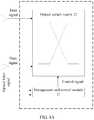
FIG. 4A is a schematic diagram of an optical switching apparatus according to an embodiment of the present invention; -
FIG. 4B is a schematic diagram of a processing process of generating a control signal according to an embodiment of the present invention; -
FIG. 4C is another schematic diagram of an optical switching apparatus according to an embodiment of the present invention; -
FIG. 4D is a schematic diagram of generating a signal by a management and control module according to an embodiment of the present invention; -
FIG. 5 is a schematic diagram of an optical receiving system according to an embodiment of the present invention; -
FIG. 6 is a schematic diagram of an optical switching system according to an embodiment of the present invention; -
FIG. 7 is a flowchart of transmitting light by an optical transmission system according to an embodiment of the present invention; and -
FIG. 8 is another flowchart of transmitting light by an optical transmission system according to an embodiment of the present invention. - To make the objectives, technical solutions, and advantages of the embodiments of the present invention clearer, the following clearly and completely describes the technical solutions in the embodiments of the present invention with reference to the accompanying drawings in the embodiments of the present invention. Apparently, the described embodiments are some but not all of the embodiments of the present invention. All other embodiments obtained by persons of ordinary skill in the art based on the embodiments of the present invention without creative efforts shall fall within the protection scope of the present invention.
- The term "and/or" in this specification describes only an association relationship for describing associated objects and represents that three relationships may exist. For example, A and/or B may represent the following three cases: Only A exists, both A and B exist, and only B exists. In addition, the character "/" in this specification generally indicates an "or" relationship between the associated objects.
- The embodiments of the present invention provide an optical transmission system. In this solution, the optical transmission system includes at least one data transmission apparatus, where any data transmission apparatus is configured to: transmit an optical label signal and a continuous data signal including an idle sequence and a data packet, and transmit the transmitted optical label signal to an optical switching apparatus, so that the optical switching apparatus builds, according to the optical label signal, a switching and transmission path for transmitting the continuous data signal transmitted by the any data transmission apparatus, where any optical label carried in the optical label signal corresponds to one data packet in the data signal, and switching and transmission paths corresponding to data signals transmitted by any two different data transmission apparatuses have different output ports. This ensures that a data transmission apparatus transmits a continuous data signal, and also ensures that each optical receiving system can receive the continuous data signal. Therefore, no preamble needs to be added before a data packet carried in a to-be-processed data signal, thereby avoiding a resource waste.
- The following describes exemplary implementation manners of the present invention in detail with reference to the accompanying drawings.
- Referring to
FIG. 2A , this embodiment of the present invention provides anoptical transmission system 200, where theoptical transmission system 200 includes at least onedata transmission apparatus 1. - Any
data transmission apparatus 1 is configured to: transmit an optical label signal and a continuous data signal including an idle sequence and a data packet, and transmit the transmitted optical label signal to anoptical switching apparatus 2, so that theoptical switching apparatus 2 builds, according to the optical label signal, a switching and transmission path for transmitting the continuous data signal transmitted by the anydata transmission apparatus 1. - Any optical label carried in the optical label signal corresponds to one data packet in the data signal, and switching and transmission paths corresponding to data signals transmitted by any two different
data transmission apparatuses 1 have different output ports. - In this embodiment of the present invention, the optical label signal and the data signal are transmitted in multiple manners. Optionally, an in-band transmission mechanism may be used for transmission (that is, the optical label signal and the data signal may be transmitted through a same channel). As shown in
FIG. 2B , in this transmission manner, an idle sequence is filled in between an optical label and a data packet to ensure data signal continuity. This transmission manner is used inEmbodiment 2. - In this embodiment of the present invention, each optical label corresponds to one piece of data. As shown in
FIG. 2B , anoptical label 1 corresponds to adata packet 1, anoptical label 2 corresponds to adata packet 2, and anoptical label 3 corresponds to adata packet 3, regardless of whether an in-band transmission mechanism or an out-of-band transmission mechanism is used. - In this embodiment of the present invention, the optical label signal is used by the
optical switching apparatus 2 to build the switching and transmission path for transmitting the continuous data signal transmitted by the anydata transmission apparatus 1, that is, a specific delay exists between a time of receiving an optical label by a management andcontrol module 21 and a time of generating a control signal to drive anoptical switch matrix 22 to complete building of the switching and transmission path. Therefore, optionally, each optical label needs to be transmitted earlier than a corresponding data packet. In this way, before a data packet arrives at theoptical switch matrix 22, the management andcontrol module 21 has generated a control signal according to a corresponding optical label, and then theoptical switch matrix 22 builds, according to the control signal, a switching and transmission path for data signal transmission. - Certainly, in actual application, an optical label may be transmitted together with a corresponding data packet, or a corresponding data packet is transmitted earlier than an optical label; in this case, delay control needs to be performed on the data packet, and the data packet is transmitted after the management and
control module 21 generates a control signal according to the optical label and builds a transmission path. - As shown in
FIG. 2C , in this embodiment of the present invention, anydata transmission apparatus 1 includes an opticallabel transmission module 11, a datapacket transmission module 12, and an idlesequence transmission module 13. - The optical
label transmission module 11 is configured to transmit an optical label. - The data
packet transmission module 12 is configured to transmit a data packet. - The idle
sequence transmission module 13 is configured to transmit an idle sequence between any optical label and any data packet that are adjacent. - In this embodiment of the present invention, the optical
label transmission module 11 is further configured to:
generate an optical label, where any optical label includes a preset switching destination output port address, a data length, and an optical label identifier. That is,FIG. 2D shows a form of an optical label. - The preset switching destination output port address in the optical label is used to build a switching and transmission path. The data length is used to calculate duration (that is, a validity time) of a control signal, to ensure completion of data signal transmission and switching. A function of the optical label identifier is to identify a start of an optical label signal in the management and
control module 21 by using the optical label identifier. -
FIG. 2E is a schematic diagram of adata transmission apparatus 1 in an in-band transmission manner. In the figure, a transmission process of thedata transmission apparatus 1 is described by using two-layer Ethernet optical packet switching as an example. A data frame is stored in an Ethernet optical packet storage module before being transmitted. In this case, a destination MAC (Medium Access Control; media access control) address needs to be read from the data frame, where the destination MAC address is used to determine a preset switching destination output port address; a data frame length is read from the data frame, where the data frame length is used to determine a data length; then, an optical label is generated according to the preset switching destination output port address, the data length, and an optical label identifier. - In this embodiment of the present invention, after obtaining the destination MAC address, the management and
control module 21 can obtain, by searching a table, a preset switching destination output port address corresponding to a destination port number. Table 1 shows a correspondence between a destination MAC address and a preset switching destination output port address, where each preset switching destination output port address corresponds to multiple MAC addresses.Table 1 Correspondence between a destination MAC address and a preset switching destination output port address Destination MAC address (in hexadecimal notation) Preset switching destination output port address (in binary notation) Preset switching destination output port address (in decimal notation) 0000 C055 0102 0000 C055 0202 0011 0011 0011 1 0000 C055 0302 0000 C055 0402 0100 1101 1001 2 0000 C055 0502 0000 C055 0602 1001 0011 1100 3 0000 C055 0702 0000 C055 0802 1100 1101 0010 4 - The
data transmission apparatus 1 included in the optical transmission system provided inEmbodiment 1 transmits both the optical label signal and the data signal. In actual application, the optical label signal and the data signal may be transmitted by different devices, or may be transmitted by using an out-of-band transmission mechanism (that is, the optical label signal and the data signal may be transmitted through different channels). As shown inFIG. 3A , when an optical label signal is transmitted by using an out-of-band transmission mechanism, an idle sequence is transmitted when no data is transmitted through a data signal transmission channel. On an optical label signal transmission link, an idle sequence or no idle sequence may be transmitted between optical label signals, as shown inEmbodiment 2. - Referring to
FIG. 3B , this embodiment of the present invention provides anoptical transmission system 200, where theoptical transmission system 200 includes at least one opticalpacket transmission apparatus 1/ and at least one opticallabel transmission apparatus 2/. - Any optical
packet transmission apparatus 1/ is configured to transmit a continuous data signal including idle information and a data packet. - Any optical
label transmission apparatus 2/ is configured to: transmit an optical label signal, and transmit the optical label signal to anoptical switching apparatus 2, so that theoptical switching apparatus 2 builds, according to the optical label signal, a switching and transmission path for transmitting a continuous data signal transmitted by a corresponding opticalpacket transmission apparatus 1/. - Any optical label carried in the optical label signal corresponds to one data packet in the corresponding data signal, and switching and transmission paths corresponding to data signals transmitted by any two different optical
packet transmission apparatuses 1/ have different output ports. - As shown in
FIG. 3C , in this embodiment of the present invention, any opticalpacket transmission apparatus 1/ includes a datapacket transmission module 11/ and an idlesequence transmission module 12/. - The data
packet transmission module 11/ is configured to transmit a data packet. - The idle
sequence transmission module 12/ is configured to transmit an idle sequence between any two adjacent data packets. - Further, in this embodiment of the present invention, the optical
label transmission module 2/ is further configured to:
generate an optical label, where any optical label includes a preset switching destination output port address, a data length, and an optical label identifier. - Referring to
FIG. 4A , this embodiment of the present invention further provides anoptical switching apparatus 2, including a management andcontrol module 21 and anoptical switch matrix 22. - The management and
control module 21 is configured to: receive an optical label signal transmitted by anoptical transmission system 200, and transmit, to theoptical switch matrix 22, a control signal generated according to the optical label signal. - The
optical switch matrix 22 is configured to: receive a continuous data signal transmitted by theoptical transmission system 200 and the control signal; adjust, according to the control signal, an optical switch unit on a link between each input port for data signal input and a corresponding output port for data signal output, to build a switching and transmission path for transmitting the continuous data signal; and input any data signal to anoptical receiving system 500 through the switching and transmission path. - Any two different switching and transmission paths have different input ports and output ports.
- If the
optical transmission system 200 transmits the data signal and the optical label signal by using an in-band transmission mechanism, optionally, 10% of a signal may be extracted to generate a control signal. After receiving the optical label signal, the management andcontrol module 21 determines a location of an optical label by using an optical label identifier, then extracts a preset switching destination output port address from the optical label to generate an actual switching destination output port address, and extracts data length information to generate duration of the control signal. - In this embodiment of the present invention,
FIG. 4B shows a processing process of generating a control signal by theoptical switching apparatus 2. - In this embodiment of the of present invention, each optical label carried in the optical label signal received by the management and
control module 21 includes a preset switching destination output port address, a data length, and an optical label identifier. - Optionally, in this embodiment of the present invention, the management and
control module 21 is specifically configured to: - determine, according to a preset switching destination output port address included in a corresponding optical label, an actual switching destination output port address corresponding to each data packet carried in a continuous data signal;
- allocate, for each idle sequence, an output port address corresponding to an idle output port, and use the output port address as an actual switching destination output port address corresponding to the idle sequence; and
- perform the following operations separately with respect to any data packet and any idle sequence:
- generating, according to an input port address and an actual switching destination output port address, a control signal for controlling a switch unit on a link between an input port corresponding to the input port address and an output port corresponding to the actual switching destination output port address; and
- transmitting the generated control signal to the
optical switch matrix 22.
- Further, in this embodiment of the present invention, the management and
control module 21 is further configured to: - calculate, with respect to any optical label in the received optical label signal and according to a data packet length included in the any optical label, a time required for transmitting a corresponding data packet; and
- determine, according to the time, a validity time of a control signal for controlling a switching and transmission path for the data packet corresponding to the optical label.
- In this embodiment of the present invention, a process of generating an actual switching destination output port address is as follows:
- Step a: Set, to m, a preset switching destination output port port_num_1 corresponding to a preset switching destination output port address.
- In this step, whether a bit error occurs on an optical label is first determined, and if the error occurs, an unoccupied output port is used as an actual switching destination output port for a data packet corresponding to the optical label, or if no error occurs, step b is performed.
- Step b: Determine a status path_state of the preset switching destination output port m; and if the path state is 1, perform step c; otherwise, perform step d.
- Step c: If the path state is 1, which indicates that the preset switching destination output port m is occupied, set the port_num_1 to 0.
- Step d: If the path state is 0, which indicates that the preset switching destination output port m is unoccupied, set the path state of the preset switching destination output port m to 1.
- In this step, an actual switching destination output port address of a data signal corresponding to a preset switching destination output port address is the preset switching destination output port address; an input port is connected to an actual switching destination output port, so as to build a switching and transmission path. That is, the corresponding data signal is input to the
optical receiving system 500 through the preset switching destination output port. - Step e: A counter build_time starts counting when a switching and transmission path starts to be built; when a numerical value on the counter build time is equal to duration of a control signal, which indicates that a validity time of the switching and transmission path expires, set both the port_num_1 and the path state of the output port m to 0, and release the link.
- According to the foregoing process, an actual switching destination output port address corresponding to each data signal is determined, and after the actual switching destination output port address corresponding to each data signal is determined, a corresponding control signal can be generated by searching a table. Table 2 shows a correspondence between a control signal and an actual switching destination output port address by using a control signal for a 4x4 banyan
optical switch matrix 22. In actual application, the actual switching destination output port address may be not stored.Table 2 Correspondence between a preset switching destination output port address and a control signal Preset switching destination output port address Actual switching destination output port address Control signal 1 2 3 0 1 2 3 4 xxxx xxxx xxxx xxxx 2 0 1 3 2 4 1 3 xxxx xxxx xxxx xxxx 1 2 3 4 1 2 3 4 xxxx xxxx xxxx xxxx - Optionally, in this embodiment of the present invention, the
optical switch matrix 22 is specifically configured to:
perform the following operations separately with respect to a control signal corresponding to any data signal: - controlling a switch unit on a link between an input port and an actual switching destination output port that are corresponding to the data signal, and connecting the input port to the actual switching destination output port to build a switching and transmission path for transmitting the any data signal; and
- inputting the any data signal to the
optical receiving system 500 through the switching and transmission path. - Optionally, in this embodiment of the present invention, the management and
control module 21 is specifically configured to: - perform the following operations separately with respect to a data packet corresponding to any optical label:
- determining whether the data packet meets a preset condition; and if yes, using, as an actual switching destination output port address, a preset switching destination output port address included in the optical label corresponding to the data packet, and generating a control signal according to the actual switching destination output port address; otherwise, determining an idle switching output port, using any switching output port in the idle switching output port as an actual switching destination output port address, and generating a control signal according to the actual switching destination output port address.
- In this embodiment of the present invention, the determining, by the management and
control module 21, whether the any data packet meets a preset condition is specifically:
determining whether the optical label corresponding to the data packet is correct and/or whether the corresponding preset switching destination output port address is occupied. - Optionally, in this embodiment of the present invention, the management and
control module 21 is specifically configured to:
use, with respect to an idle sequence, the any switching output port in the determined idle switching output port as an actual switching destination output port address of the idle sequence, and generate a control signal according to the actual switching destination output port address. - In actual application, a preset switching destination output port corresponding to a data signal may have been occupied; in this case, to ensure that data signal transmission is performed on an idle switching destination output port all the time and further ensure data signal transmission continuity, in this embodiment of the present invention, optionally, the management and
control module 21 is specifically configured to: - if any two different data packets arrive at the
optical switch matrix 22 simultaneously, and preset switching destination output port addresses corresponding to the two data packets respectively are the same and unoccupied, use a preset switching destination output port address corresponding to one data packet as a first actual switching destination output port address of the data packet and use a determined idle switching output port address as a second actual switching destination output port address of the other data packet; and - generate a control signal according to the first actual switching destination output port address and the second actual switching destination output port address.
- In this way, even if a data signal cannot be switched to a preset switching destination output port (the preset switching destination output port is occupied), the data signal can be switched to another idle switching destination output port, to maintain data signal transmission continuity. Therefore, data signal output is performed on each switching destination output port all the time regardless of a switching manner.
- For example, it is assumed that there are totally four switching destination input ports and four switching destination output ports, where switching
destination output ports destination output port 4 is idle. In this case, if a preset switching destination output port generated for a fourth data signal is the switchingdestination output port 3, but the switchingdestination output port 3 has been occupied currently, the fourth data signal is switched to the switchingdestination output port 4 instead of being discarded. That is, a corresponding actual switching destination output port passed through by the fourth data signal is the switchingdestination output port 4; the fourth data signal is input to theoptical receiving system 500 through the switchingdestination output port 4. Because a control signal corresponding to "1230" and a control signal corresponding to "1234" are the same, the management andcontrol module 21 searches, according to "1230", the table to generate the control signal. Therefore, data signal transmission continuity at the switching destination output ports is ensured. - In this embodiment of the present invention, in some optical switching systems, different
optical transmission systems 200 usually have different transmission power, and a different interactive transmission path through which a data signal passes in theoptical switch matrix 22 results in a different transmission loss. In this case, data signals received through a same switching destination output port from differentdata transmission apparatuses 1 or opticalpacket transmission apparatuses 1/ have different power. Due to such a difference between the data signals, theoptical receiving system 500 needs to receive the data signals by using a burst-mode optical-to-electrical conversion device. In this way, the problem in the background still exists. To avoid the problem in the background, in this embodiment of the present invention, further referring toFIG. 4C , apower equilibrium unit 23 is further included and configured to perform power compensation before a data packet is input to the optical receiving system through a corresponding actual switching destination output port. - As shown in
FIG. 4D , in this embodiment of the present invention, the management andcontrol module 21 is further configured to: - separately calculate a first power attenuation value after each data packet included in the continuous data signal passes through a corresponding switching and transmission path, and/or a second power attenuation value of an optical switch unit on the corresponding switching and transmission path; and
- calculate a total power attenuation value according to the first power attenuation value and/or the second power attenuation value, and transmit the total power attenuation value to the
power equilibrium unit 23, so that thepower equilibrium unit 23 performs power compensation before a data packet is input to theoptical receiving system 500 through a corresponding actual switching destination output port. - The first power attenuation value is used to compensate for a transmission loss in the switching and transmission path. The second power attenuation value is mainly used to compensate for a loss in the
optical switch matrix 22. The loss in theoptical switch matrix 22 is constant and is related to an interactive transmission path for data signal transmission. Therefore, a value of the loss in theoptical switch matrix 22 may be determined according to the generated control signal, that is, after an actual switching destination output port address is generated, the second power attenuation value is generated by searching the table. - In this embodiment of the present invention, the first power attenuation value and the second power attenuation value are added to obtain a power value that needs to be compensated for a data signal transmitted through each transmission path. In an implementation process, power compensation may be performed by selecting a proper amplifier according to a type of a data signal transferred through a switching and transmission path. For example, in an amplifier array, SOAs (Semiconductor Optical Amplifier, semiconductor optical amplifier), burst-mode EDFAs (Erbium-doped Fiber Amplifier, erbium-doped fiber amplifier), or the like may be used.
- Further, when the second power attenuation value is relatively small, the second power attenuation value may be omitted and only the first power attenuation value is considered. In this case, because the
data transmission apparatus 1 transmits a continuous data signal, thepower equilibrium unit 23 may perform power compensation by using a continuous amplification apparatus, further reducing system complexity and reducing costs. - In this embodiment of the present invention, as shown in
FIG. 5 , anoptical receiving system 500 is further provided, including anoptical receiver 3 and aprocessor 4. - Each
optical receiver 3 is configured to receive a continuous data signal transmitted by anoptical transmission system 200. - The
processor 4 is configured to process a data packet in the received continuous data signal. - In this embodiment of the present invention, as shown in
FIG. 6 , an optical switching system is further provided, including:
theoptical transmission system 200 inFIG. 2A orFIG. 3B , theoptical switching apparatus 2 shown inFIG. 4A , and theoptical receiving system 500 shown inFIG. 5 . - As shown in
FIG. 7 , an embodiment of the present invention further provides a method for transmitting light by an optical transmission system, where a detailed process of the method is as follows: - Step 700: Transmit an optical label signal and a continuous data signal including an idle sequence and a data packet.
- Step 710: Transmit the transmitted optical label signal to an optical switching apparatus, so that the optical switching apparatus builds, according to the optical label signal, a switching and transmission path for transmitting a continuous data signal transmitted by any data transmission apparatus, where any optical label carried in the optical label signal corresponds to one data packet in the data signal, and switching and transmission paths corresponding to data signals transmitted by any two different data transmission apparatuses have different output ports.
- In this embodiment of the present invention, optionally, if the optical label signal and the continuous data signal are transmitted in an in-band transmission manner, an idle sequence is between any optical label and an adjacent data packet; or
if the optical label signal and the continuous data signal are transmitted in an out-of-band transmission manner, an idle sequence is between any two adjacent data packets. - Further, in this embodiment of the present invention, before the transmitting an optical label signal, the method further includes:
- generating an optical label, where any optical label includes a preset switching destination output port address, a data length, and an optical label identifier.
- As shown in
FIG. 8 , an embodiment of the present invention further provides another method for transmitting light by an optical transmission system, where a detailed process of the method is as follows: - Step 800: Receive an optical label signal and a continuous data signal that are transmitted by an optical transmission system.
- Step 810: Generate a control signal according to the optical label signal.
- Step 820: Adjust, according to the control signal, an optical switch on a link between each input port for data signal input and a corresponding output port for data signal output, to build a switching and transmission path for transmitting the continuous data signal.
- Step 830: Input any data signal to an optical receiving system through the switching and transmission path, where any two different switching and transmission paths have different input ports and output ports.
- In this embodiment of the present invention, optionally, each optical label carried in the optical label signal includes a preset switching destination output port address, a data length, and an optical label identifier.
- In this embodiment of the present invention, optionally, the generating a control signal according to the optical label signal specifically includes:
- determining, according to a preset switching destination output port address included in a corresponding optical label, an actual switching destination output port address corresponding to each data packet carried in a continuous data signal;
- allocating, for each idle sequence, an output port address corresponding to an idle output port, and using the output port address as an actual switching destination output port address corresponding to the idle sequence; and
- performing the following operation with respect to any data packet and any idle sequence:
generating, according to an input port address and an actual switching destination output port address, a control signal for controlling a switch unit on a link between an input port corresponding to the input port address and an output port corresponding to the actual switching destination output port address. - In this embodiment of the present invention, further, after the generating a control signal for controlling a switch unit on a link between an input port corresponding to the input port address and an output port corresponding to the actual switching destination output port address, the method further includes:
- calculating, with respect to any optical label in the received optical label signal and according to a data packet length included in the any optical label, a time required for transmitting a corresponding data packet; and
- determining, according to the time, a validity time of a control signal for controlling a switching and transmission path for the data packet corresponding to the optical label.
- In this embodiment of the present invention, optionally, the adjusting, according to the control signal, an optical switch on a link between each input port for data signal input and a corresponding output port for data signal output, to build a switching and transmission path for transmitting the continuous data signal specifically includes:
performing the following operations separately with respect to a control signal corresponding to any data signal:
controlling a switch unit on a link between an input port and an actual switching destination output port that are corresponding to the data signal, and connecting the input port to the actual switching destination output port to build a switching and transmission path for transmitting the any data signal. - In this embodiment of the present invention, optionally, the generating a control signal according to the optical label signal specifically includes:
performing the following operations separately with respect to a data packet corresponding to any optical label:
determining whether the data packet meets a preset condition; and if yes, using, as an actual switching destination output port address, a preset switching destination output port address included in the optical label corresponding to the data packet, and generating a control signal according to the actual switching destination output port address; otherwise, determining an idle switching output port, using any switching output port in the idle switching output port as an actual switching destination output port address, and generating a control signal according to the actual switching destination output port address. - In this embodiment of the present invention, optionally, the determining whether the data packet meets a preset condition specifically includes:
determining whether the optical label corresponding to the data packet is correct and/or whether the corresponding preset switching destination output port address is occupied. - In this embodiment of the present invention, optionally, the generating a control signal according to the optical label signal specifically includes:
using, with respect to an idle sequence, the any switching output port in the determined idle switching output port as an actual switching destination output port address of the idle sequence, and generating a control signal according to the actual switching destination output port address. - In this embodiment of the present invention, optionally, the generating a control signal according to the optical label signal specifically includes:
- if any two different data packets arrive at the optical switch matrix simultaneously, and preset switching destination output port addresses corresponding to the two data packets respectively are the same and unoccupied, using a preset switching destination output port address corresponding to one data packet as a first actual switching destination output port address of the data packet and using a determined idle switching output port address as a second actual switching destination output port address of the other data packet; and
- generating a control signal according to the first actual switching destination output port address and the second actual switching destination output port address.
- In this embodiment of the present invention, further, after the adjusting, according to the control signal, an optical switch on a link between each input port for data signal input and a corresponding output port for data signal output, to build a switching and transmission path for transmitting the continuous data signal, and before the inputting any data signal to an optical receiving system through the switching and transmission path, the method further includes:
- separately calculating a first power attenuation value after each data packet included in the continuous data signal passes through a corresponding switching and transmission path, and/or a second power attenuation value of an optical switch unit on the corresponding switching and transmission path;
- calculating a total power attenuation value according to the first power attenuation value and/or the second power attenuation value; and performing power compensation before a data packet is input to the optical receiving system through a corresponding actual switching destination output port.
- In conclusion, the embodiments of the present invention provide an optical transmission system. In this solution, the optical transmission system includes at least one data transmission apparatus, where any data transmission apparatus is configured to: transmit an optical label signal and a continuous data signal including an idle sequence and a data packet, and transmit the transmitted optical label signal to an optical switching apparatus, so that the optical switching apparatus builds, according to the optical label signal, a switching and transmission path for transmitting the continuous data signal transmitted by the any data transmission apparatus, where any optical label carried in the optical label signal corresponds to one data packet in the data signal, and switching and transmission paths corresponding to data signals transmitted by any two different data transmission apparatuses have different output ports. This ensures that a data transmission apparatus transmits a continuous data signal, and also ensures that each optical receiving system can receive the continuous data signal. Therefore, no preamble needs to be added before a data packet carried in a to-be-processed data signal, thereby avoiding a resource waste.
- The present invention is described with reference to the flowcharts and/or block diagrams of the method, the device (system), and the computer program product according to the embodiments of the present invention. It should be understood that computer program instructions may be used to implement each process and/or each block in the flowcharts and/or the block diagrams and a combination of a process and/or a block in the flowcharts and/or the block diagrams. These computer program instructions may be provided for a general-purpose computer, a dedicated computer, an embedded processor, or a processor of any other programmable data processing device to generate a machine, so that the instructions executed by a computer or a processor of any other programmable data processing device generate an apparatus for implementing a specific function in one or more processes in the flowcharts and/or in one or more blocks in the block diagrams.
- These computer program instructions may also be stored in a computer readable memory that can instruct the computer or any other programmable data processing device to work in a specific manner, so that the instructions stored in the computer readable memory generate an artifact that includes an instruction apparatus. The instruction apparatus implements a specific function in one or more processes in the flowcharts and/or in one or more blocks in the block diagrams.
- These computer program instructions may also be loaded onto a computer or another programmable data processing device, so that a series of operations and steps are performed on the computer or the another programmable device, thereby generating computer-implemented processing. Therefore, the instructions executed on the computer or the another programmable device provide steps for implementing a specific function in one or more processes in the flowcharts and/or in one or more blocks in the block diagrams.
- Although some preferred embodiments of the present invention have been described, persons skilled in the art can make changes and modifications to these embodiments once they learn the basic inventive concept. Therefore, the following claims are intended to be construed as to cover the preferred embodiments and all changes and modifications falling within the scope of the present invention.
Claims (11)
- An optical transmission system, comprising:an optical switching apparatus (2),at least one optical packet transmission apparatus (1'), configured to transmit a continuous data signal comprising an idle sequence and a data packet, andat least one optical label transmission apparatus (2'), configured to transmit an optical label signal, and transmit the optical label signal to an optical switching apparatus (2),wherein the optical switching apparatus (2) is configured to build, according to the optical label signal, a switching and transmission path for transmitting a continuous data signal transmitted by a corresponding optical packet transmission apparatus (1'), whereinany optical label carried in the optical label signal corresponds to one data packet in the corresponding data signal, and switching and transmission paths corresponding to data signals transmitted by the any two different optical packet transmission apparatuses (1') have different output ports.
- The optical transmission system according to claim 1, wherein any optical packet transmission apparatus (1') comprises a data packet transmission module (11') and an idle sequence transmission module (12'), wherein
the data packet transmission module (11') is configured to transmit a data packet; and the idle sequence transmission module (12') is configured to transmit an idle sequence between any two adjacent data packets. - The optical transmission system according to according to claim 1 or 2, wherein the optical switching apparatus comprises a management and control module (21), and an optical switch matrix (22), wherein
the management and control module (21) is configured to: receive an optical label signal transmitted by the optical transmission system, and transmit, to the optical switch matrix (22), a control signal generated according to the optical label signal; and
the optical switch matrix (22) is configured to: receive a continuous data signal transmitted by the optical transmission system and the control signal; adjust, according to the control signal, an optical switch unit on a link between each input port for data signal input and a corresponding output port for data signal output, to build a switching and transmission path for transmitting the continuous data signal; and input the any data signal to an optical receiving system through the switching and transmission path, wherein
any two different switching and transmission paths have different input ports and output ports. - The optical switching apparatus according to claim 3, wherein the management and control module (21) is specifically configured to:determine, according to a preset switching destination output port address comprised in a corresponding optical label, an actual switching destination output port address corresponding to each data packet carried in a continuous data signal;allocate, for each idle sequence, an output port address corresponding to an idle output port, and use the output port address as an actual switching destination output port address corresponding to the idle sequence; andperform the following operations separately with respect to any data packet and any idle sequence:generating, according to an input port address and an actual switching destination output port address, a control signal for controlling a switch unit on a link between an input port corresponding to the input port address and an output port corresponding to the actual switching destination output port address; andtransmitting the generated control signal to the optical switch matrix.
- The optical switching apparatus according to claim 3 or 4, wherein the management and control module (21) is specifically configured to:if any two different data packets arrive at the optical switch matrix (22) simultaneously, and preset switching destination output port addresses corresponding to the two data packets respectively are the same and unoccupied, use a preset switching destination output port address corresponding to one data packet as a first actual switching destination output port address of the data packet and use a determined idle switching output port address as a second actual switching destination output port address of the other data packet; andgenerate a control signal according to the first actual switching destination output port address and the second actual switching destination output port address.
- The optical switching apparatus according to any one of claims 3 to 5, wherein the management and control module (21) is further configured to:separately calculate a first power attenuation value after each data packet comprised in the continuous data signal passes through a corresponding switching and transmission path, and/or a second power attenuation value of an optical switch unit on the corresponding switching and transmission path; andcalculate a total power attenuation value according to the first power attenuation value and/or the second power attenuation value, and transmit the total power attenuation value to a power equilibrium unit, so that the power equilibrium unit performs power compensation before a data packet is input to the optical receiving system through a corresponding actual switching destination output port.
- The optical switching apparatus according to claim 6, further comprising the power equilibrium unit, configured to perform power compensation before a data packet is input to the optical receiving system through a corresponding actual switching destination output port.
- A control method, comprising:receiving (800) an optical label signal and a continuous data signal that are transmitted by an optical transmission system;generating (810) a control signal according to the optical label signal;adjusting (820), according to the control signal, an optical switch on a link between each input port for data signal input and a corresponding output port for data signal output, to build a switching and transmission path for transmitting the continuous data signal; andinputting (830) the any data signal to an optical receiving system through the switching and transmission path, whereinany two different switching and transmission paths have different input ports and output ports.
- The method according to claim 8, wherein the generating (810) a control signal according to the optical label signal specifically comprises:determining, according to a preset switching destination output port address comprised in a corresponding optical label, an actual switching destination output port address corresponding to each data packet carried in a continuous data signal;allocating, for each idle sequence, an output port address corresponding to an idle output port, and using the output port address as an actual switching destination output port address corresponding to the idle sequence; andperforming the following operation with respect to any data packet and any idle sequence:
generating, according to an input port address and an actual switching destination output port address, a control signal for controlling a switch unit on a link between an input port corresponding to the input port address and an output port corresponding to the actual switching destination output port address. - The method according to claims 8 or 9, wherein the generating (810) a control signal according to the optical label signal specifically comprises:if any two different data packets arrive at the optical switch matrix simultaneously, and preset switching destination output port addresses corresponding to the two data packets respectively are the same and unoccupied, using a preset switching destination output port address corresponding to one data packet as a first actual switching destination output port address of the data packet and using a determined idle switching output port address as a second actual switching destination output port address of the other data packet; andgenerating a control signal according to the first actual switching destination output port address and the second actual switching destination output port address.
- The method according to any one of claims 8 to 10, after the adjusting (820), according to the control signal, an optical switch on a link between each input port for data signal input and a corresponding output port for data signal output, to build a switching and transmission path for transmitting the continuous data signal, and before the inputting (830) the any data signal to an optical receiving system through the switching and transmission path, further comprising:separately calculating a first power attenuation value after each data packet comprised in the continuous data signal passes through a corresponding switching and transmission path, and/or a second power attenuation value of an optical switch unit on the corresponding switching and transmission path;calculating a total power attenuation value according to the first power attenuation value and/or the second power attenuation value; andperforming power compensation before a data packet is input to the optical receiving system through a corresponding actual switching destination output port.
Applications Claiming Priority (2)
| Application Number | Priority Date | Filing Date | Title |
|---|---|---|---|
| CN201410152709.3A CN105099565B (en) | 2014-04-16 | 2014-04-16 | A kind of light emission system and launching technique, optic switching device and control method |
| PCT/CN2014/089467 WO2015158127A1 (en) | 2014-04-16 | 2014-10-24 | Optical transmission system and transmission method, optical switching device and control method |
Publications (3)
| Publication Number | Publication Date |
|---|---|
| EP3133786A1 EP3133786A1 (en) | 2017-02-22 |
| EP3133786A4 EP3133786A4 (en) | 2017-04-26 |
| EP3133786B1 true EP3133786B1 (en) | 2018-09-26 |
Family
ID=54323454
Family Applications (1)
| Application Number | Title | Priority Date | Filing Date |
|---|---|---|---|
| EP14889759.8A Not-in-force EP3133786B1 (en) | 2014-04-16 | 2014-10-24 | Optical transmission system and transmission method, optical switching device and control method |
Country Status (7)
| Country | Link |
|---|---|
| US (1) | US10009672B2 (en) |
| EP (1) | EP3133786B1 (en) |
| KR (1) | KR101909547B1 (en) |
| CN (1) | CN105099565B (en) |
| BR (1) | BR112016024046B1 (en) |
| CA (1) | CA2945849C (en) |
| WO (1) | WO2015158127A1 (en) |
Families Citing this family (5)
| Publication number | Priority date | Publication date | Assignee | Title |
|---|---|---|---|---|
| CN112929283B (en) | 2019-12-06 | 2024-04-02 | 中兴通讯股份有限公司 | Data processing method, device, equipment and storage medium |
| CN113825042B (en) * | 2020-06-18 | 2024-09-03 | 深圳市中兴微电子技术有限公司 | Data access method, device, chip and computer storage medium |
| CN115102914A (en) * | 2021-03-05 | 2022-09-23 | 中兴通讯股份有限公司 | Data exchange system, method and storage medium |
| CN116827445A (en) * | 2023-06-20 | 2023-09-29 | 佛山市兴颂机器人科技有限公司 | A dynamic power adjustment method and system for optical communication equipment |
| CN116827440A (en) * | 2023-06-21 | 2023-09-29 | 佛山市兴颂机器人科技有限公司 | Optical communication equipment, signal transmission system and power dynamic adjustment method |
Family Cites Families (12)
| Publication number | Priority date | Publication date | Assignee | Title |
|---|---|---|---|---|
| US7050717B2 (en) * | 2000-09-06 | 2006-05-23 | The Regents Of The University Of California | System and method of all optical label swapping using two-stage optical wavelength converters |
| WO2003050708A1 (en) * | 2001-12-07 | 2003-06-19 | Vitesse Semiconductor Company | A method and system for transporting information via the xgmii or fiber channel standard |
| US7181140B2 (en) * | 2002-04-17 | 2007-02-20 | Intel Corporation | Method and apparatus for implementing and networking a semiconductor-based optical burst switching module within optical networks |
| US7315693B2 (en) * | 2003-10-22 | 2008-01-01 | Intel Corporation | Dynamic route discovery for optical switched networks |
| CN100558082C (en) * | 2007-03-20 | 2009-11-04 | 华为技术有限公司 | A communication system, a label switching router, and a routing switching method |
| CN100471162C (en) * | 2007-04-28 | 2009-03-18 | 杭州华三通信技术有限公司 | A method for issuing and processing virtual circuit information and provider edge equipment |
| CN101426152B (en) * | 2008-12-08 | 2011-03-16 | 电子科技大学 | Data transmission method for integrated mixed optical network based on burst exchange |
| CN101877800A (en) * | 2009-12-03 | 2010-11-03 | 上海交通大学 | Test Method of Differential Delay in Optical Network |
| CN202121601U (en) * | 2011-06-20 | 2012-01-18 | 东南大学 | Transmitting and receiving device of multicast optical code packet head |
| CN102355609B (en) * | 2011-10-18 | 2014-05-14 | 成都优博创技术有限公司 | Received signal strength indicator (RSSI) Trigger processing device of double-channel light module |
| CN102882811B (en) * | 2012-09-10 | 2016-04-13 | 西安电子科技大学 | Based on data center light interconnection network system and the communication means of array waveguide grating |
| EP2988442B1 (en) * | 2013-05-13 | 2017-10-04 | Huawei Technologies Co., Ltd. | Receiving device and optical switching network apparatus |
-
2014
- 2014-04-16 CN CN201410152709.3A patent/CN105099565B/en active Active
- 2014-10-24 BR BR112016024046-4A patent/BR112016024046B1/en not_active IP Right Cessation
- 2014-10-24 WO PCT/CN2014/089467 patent/WO2015158127A1/en not_active Ceased
- 2014-10-24 KR KR1020167031465A patent/KR101909547B1/en not_active Expired - Fee Related
- 2014-10-24 CA CA2945849A patent/CA2945849C/en active Active
- 2014-10-24 EP EP14889759.8A patent/EP3133786B1/en not_active Not-in-force
-
2016
- 2016-10-14 US US15/293,989 patent/US10009672B2/en active Active
Non-Patent Citations (1)
| Title |
|---|
| None * |
Also Published As
| Publication number | Publication date |
|---|---|
| EP3133786A4 (en) | 2017-04-26 |
| BR112016024046A2 (en) | 2017-10-10 |
| CN105099565A (en) | 2015-11-25 |
| CA2945849C (en) | 2019-04-30 |
| US20170034606A1 (en) | 2017-02-02 |
| KR20160146805A (en) | 2016-12-21 |
| WO2015158127A1 (en) | 2015-10-22 |
| CN105099565B (en) | 2018-04-10 |
| CA2945849A1 (en) | 2015-10-22 |
| US10009672B2 (en) | 2018-06-26 |
| EP3133786A1 (en) | 2017-02-22 |
| BR112016024046B1 (en) | 2023-04-11 |
| KR101909547B1 (en) | 2018-10-18 |
Similar Documents
| Publication | Publication Date | Title |
|---|---|---|
| JP6445706B2 (en) | Communication method, apparatus, and system applied to multi-wavelength passive optical network | |
| JP4969473B2 (en) | Optical access network and optical communication path switching control system | |
| EP3364605A1 (en) | Data centre network system and signal transmission system | |
| CN108028801B (en) | A SDN-based ARP implementation method and device | |
| EP1965601B1 (en) | Optical transmission system and optical transmission method | |
| US10009672B2 (en) | Optical transmission system and transmission method, optical switching apparatus, and control method | |
| US20240098392A1 (en) | Intelligent fiber to the room (fttr) gateway | |
| EP4037260B1 (en) | Generating a forwarding table in a forwarding device | |
| KR20150022859A (en) | Optical network terminal management control interface message transmission method and system, and corresponding device | |
| EP3716641A1 (en) | Data transport method, device and system | |
| WO2014181174A1 (en) | Method and apparatus for reconfiguring wavelength of optical network unit | |
| WO2021171569A1 (en) | Optical network having optical core part and node using time-slotted reception | |
| KR101043851B1 (en) | Optical communication system, optical communication method and communication device | |
| US8358932B2 (en) | All-optical data center network | |
| US9948569B2 (en) | Station-side terminal apparatus, and path switching method | |
| JP6603644B2 (en) | Optical concentrator network system and signal transmission method | |
| CN112995804B (en) | Optical switching method, device and system | |
| Zervas et al. | A fully functional application-aware optical burst switched network test-bed | |
| CN109698982B (en) | Control channel implementation method, device, equipment, storage medium and processing method | |
| Alam et al. | Performance evaluation of throughput in optical burst switching | |
| JP5116495B2 (en) | Optical communication system and station side device | |
| CN103686465B (en) | Optical network node, optical network unit and communicating between the optical network unit of low delay | |
| JP5661665B2 (en) | Branched optical access system and method |
Legal Events
| Date | Code | Title | Description |
|---|---|---|---|
| STAA | Information on the status of an ep patent application or granted ep patent |
Free format text: STATUS: THE INTERNATIONAL PUBLICATION HAS BEEN MADE |
|
| PUAI | Public reference made under article 153(3) epc to a published international application that has entered the european phase |
Free format text: ORIGINAL CODE: 0009012 |
|
| STAA | Information on the status of an ep patent application or granted ep patent |
Free format text: STATUS: REQUEST FOR EXAMINATION WAS MADE |
|
| 17P | Request for examination filed |
Effective date: 20161025 |
|
| AK | Designated contracting states |
Kind code of ref document: A1 Designated state(s): AL AT BE BG CH CY CZ DE DK EE ES FI FR GB GR HR HU IE IS IT LI LT LU LV MC MK MT NL NO PL PT RO RS SE SI SK SM TR |
|
| AX | Request for extension of the european patent |
Extension state: BA ME |
|
| A4 | Supplementary search report drawn up and despatched |
Effective date: 20170324 |
|
| RIC1 | Information provided on ipc code assigned before grant |
Ipc: H04Q 11/00 20060101ALI20170320BHEP Ipc: H04L 12/18 20060101ALI20170320BHEP Ipc: H04L 12/933 20130101AFI20170320BHEP Ipc: H04L 12/723 20130101ALI20170320BHEP |
|
| DAX | Request for extension of the european patent (deleted) | ||
| GRAP | Despatch of communication of intention to grant a patent |
Free format text: ORIGINAL CODE: EPIDOSNIGR1 |
|
| STAA | Information on the status of an ep patent application or granted ep patent |
Free format text: STATUS: GRANT OF PATENT IS INTENDED |
|
| RIC1 | Information provided on ipc code assigned before grant |
Ipc: H04L 12/723 20130101ALI20180322BHEP Ipc: H04L 12/933 20130101AFI20180322BHEP Ipc: H04Q 11/00 20060101ALI20180322BHEP Ipc: H04L 12/18 20060101ALI20180322BHEP |
|
| INTG | Intention to grant announced |
Effective date: 20180416 |
|
| GRAS | Grant fee paid |
Free format text: ORIGINAL CODE: EPIDOSNIGR3 |
|
| GRAA | (expected) grant |
Free format text: ORIGINAL CODE: 0009210 |
|
| STAA | Information on the status of an ep patent application or granted ep patent |
Free format text: STATUS: THE PATENT HAS BEEN GRANTED |
|
| AK | Designated contracting states |
Kind code of ref document: B1 Designated state(s): AL AT BE BG CH CY CZ DE DK EE ES FI FR GB GR HR HU IE IS IT LI LT LU LV MC MK MT NL NO PL PT RO RS SE SI SK SM TR |
|
| REG | Reference to a national code |
Ref country code: GB Ref legal event code: FG4D |
|
| REG | Reference to a national code |
Ref country code: CH Ref legal event code: EP |
|
| REG | Reference to a national code |
Ref country code: AT Ref legal event code: REF Ref document number: 1047349 Country of ref document: AT Kind code of ref document: T Effective date: 20181015 |
|
| REG | Reference to a national code |
Ref country code: IE Ref legal event code: FG4D |
|
| REG | Reference to a national code |
Ref country code: DE Ref legal event code: R096 Ref document number: 602014033202 Country of ref document: DE |
|
| REG | Reference to a national code |
Ref country code: NL Ref legal event code: MP Effective date: 20180926 |
|
| PG25 | Lapsed in a contracting state [announced via postgrant information from national office to epo] |
Ref country code: NO Free format text: LAPSE BECAUSE OF FAILURE TO SUBMIT A TRANSLATION OF THE DESCRIPTION OR TO PAY THE FEE WITHIN THE PRESCRIBED TIME-LIMIT Effective date: 20181226 Ref country code: FI Free format text: LAPSE BECAUSE OF FAILURE TO SUBMIT A TRANSLATION OF THE DESCRIPTION OR TO PAY THE FEE WITHIN THE PRESCRIBED TIME-LIMIT Effective date: 20180926 Ref country code: GR Free format text: LAPSE BECAUSE OF FAILURE TO SUBMIT A TRANSLATION OF THE DESCRIPTION OR TO PAY THE FEE WITHIN THE PRESCRIBED TIME-LIMIT Effective date: 20181227 Ref country code: RS Free format text: LAPSE BECAUSE OF FAILURE TO SUBMIT A TRANSLATION OF THE DESCRIPTION OR TO PAY THE FEE WITHIN THE PRESCRIBED TIME-LIMIT Effective date: 20180926 Ref country code: LT Free format text: LAPSE BECAUSE OF FAILURE TO SUBMIT A TRANSLATION OF THE DESCRIPTION OR TO PAY THE FEE WITHIN THE PRESCRIBED TIME-LIMIT Effective date: 20180926 Ref country code: SE Free format text: LAPSE BECAUSE OF FAILURE TO SUBMIT A TRANSLATION OF THE DESCRIPTION OR TO PAY THE FEE WITHIN THE PRESCRIBED TIME-LIMIT Effective date: 20180926 Ref country code: BG Free format text: LAPSE BECAUSE OF FAILURE TO SUBMIT A TRANSLATION OF THE DESCRIPTION OR TO PAY THE FEE WITHIN THE PRESCRIBED TIME-LIMIT Effective date: 20181226 |
|
| REG | Reference to a national code |
Ref country code: LT Ref legal event code: MG4D |
|
| PG25 | Lapsed in a contracting state [announced via postgrant information from national office to epo] |
Ref country code: LV Free format text: LAPSE BECAUSE OF FAILURE TO SUBMIT A TRANSLATION OF THE DESCRIPTION OR TO PAY THE FEE WITHIN THE PRESCRIBED TIME-LIMIT Effective date: 20180926 Ref country code: AL Free format text: LAPSE BECAUSE OF FAILURE TO SUBMIT A TRANSLATION OF THE DESCRIPTION OR TO PAY THE FEE WITHIN THE PRESCRIBED TIME-LIMIT Effective date: 20180926 Ref country code: HR Free format text: LAPSE BECAUSE OF FAILURE TO SUBMIT A TRANSLATION OF THE DESCRIPTION OR TO PAY THE FEE WITHIN THE PRESCRIBED TIME-LIMIT Effective date: 20180926 |
|
| REG | Reference to a national code |
Ref country code: AT Ref legal event code: MK05 Ref document number: 1047349 Country of ref document: AT Kind code of ref document: T Effective date: 20180926 |
|
| PG25 | Lapsed in a contracting state [announced via postgrant information from national office to epo] |
Ref country code: NL Free format text: LAPSE BECAUSE OF FAILURE TO SUBMIT A TRANSLATION OF THE DESCRIPTION OR TO PAY THE FEE WITHIN THE PRESCRIBED TIME-LIMIT Effective date: 20180926 Ref country code: AT Free format text: LAPSE BECAUSE OF FAILURE TO SUBMIT A TRANSLATION OF THE DESCRIPTION OR TO PAY THE FEE WITHIN THE PRESCRIBED TIME-LIMIT Effective date: 20180926 Ref country code: ES Free format text: LAPSE BECAUSE OF FAILURE TO SUBMIT A TRANSLATION OF THE DESCRIPTION OR TO PAY THE FEE WITHIN THE PRESCRIBED TIME-LIMIT Effective date: 20180926 Ref country code: IS Free format text: LAPSE BECAUSE OF FAILURE TO SUBMIT A TRANSLATION OF THE DESCRIPTION OR TO PAY THE FEE WITHIN THE PRESCRIBED TIME-LIMIT Effective date: 20190126 Ref country code: PL Free format text: LAPSE BECAUSE OF FAILURE TO SUBMIT A TRANSLATION OF THE DESCRIPTION OR TO PAY THE FEE WITHIN THE PRESCRIBED TIME-LIMIT Effective date: 20180926 Ref country code: CZ Free format text: LAPSE BECAUSE OF FAILURE TO SUBMIT A TRANSLATION OF THE DESCRIPTION OR TO PAY THE FEE WITHIN THE PRESCRIBED TIME-LIMIT Effective date: 20180926 Ref country code: RO Free format text: LAPSE BECAUSE OF FAILURE TO SUBMIT A TRANSLATION OF THE DESCRIPTION OR TO PAY THE FEE WITHIN THE PRESCRIBED TIME-LIMIT Effective date: 20180926 Ref country code: EE Free format text: LAPSE BECAUSE OF FAILURE TO SUBMIT A TRANSLATION OF THE DESCRIPTION OR TO PAY THE FEE WITHIN THE PRESCRIBED TIME-LIMIT Effective date: 20180926 Ref country code: IT Free format text: LAPSE BECAUSE OF FAILURE TO SUBMIT A TRANSLATION OF THE DESCRIPTION OR TO PAY THE FEE WITHIN THE PRESCRIBED TIME-LIMIT Effective date: 20180926 |
|
| PG25 | Lapsed in a contracting state [announced via postgrant information from national office to epo] |
Ref country code: PT Free format text: LAPSE BECAUSE OF FAILURE TO SUBMIT A TRANSLATION OF THE DESCRIPTION OR TO PAY THE FEE WITHIN THE PRESCRIBED TIME-LIMIT Effective date: 20190126 Ref country code: SK Free format text: LAPSE BECAUSE OF FAILURE TO SUBMIT A TRANSLATION OF THE DESCRIPTION OR TO PAY THE FEE WITHIN THE PRESCRIBED TIME-LIMIT Effective date: 20180926 Ref country code: SM Free format text: LAPSE BECAUSE OF FAILURE TO SUBMIT A TRANSLATION OF THE DESCRIPTION OR TO PAY THE FEE WITHIN THE PRESCRIBED TIME-LIMIT Effective date: 20180926 |
|
| REG | Reference to a national code |
Ref country code: CH Ref legal event code: PL |
|
| REG | Reference to a national code |
Ref country code: BE Ref legal event code: MM Effective date: 20181031 |
|
| REG | Reference to a national code |
Ref country code: DE Ref legal event code: R097 Ref document number: 602014033202 Country of ref document: DE |
|
| PG25 | Lapsed in a contracting state [announced via postgrant information from national office to epo] |
Ref country code: LU Free format text: LAPSE BECAUSE OF NON-PAYMENT OF DUE FEES Effective date: 20181024 |
|
| REG | Reference to a national code |
Ref country code: IE Ref legal event code: MM4A |
|
| PG25 | Lapsed in a contracting state [announced via postgrant information from national office to epo] |
Ref country code: DK Free format text: LAPSE BECAUSE OF FAILURE TO SUBMIT A TRANSLATION OF THE DESCRIPTION OR TO PAY THE FEE WITHIN THE PRESCRIBED TIME-LIMIT Effective date: 20180926 Ref country code: MC Free format text: LAPSE BECAUSE OF FAILURE TO SUBMIT A TRANSLATION OF THE DESCRIPTION OR TO PAY THE FEE WITHIN THE PRESCRIBED TIME-LIMIT Effective date: 20180926 |
|
| PLBE | No opposition filed within time limit |
Free format text: ORIGINAL CODE: 0009261 |
|
| STAA | Information on the status of an ep patent application or granted ep patent |
Free format text: STATUS: NO OPPOSITION FILED WITHIN TIME LIMIT |
|
| GBPC | Gb: european patent ceased through non-payment of renewal fee |
Effective date: 20181226 |
|
| PG25 | Lapsed in a contracting state [announced via postgrant information from national office to epo] |
Ref country code: CH Free format text: LAPSE BECAUSE OF NON-PAYMENT OF DUE FEES Effective date: 20181031 Ref country code: LI Free format text: LAPSE BECAUSE OF NON-PAYMENT OF DUE FEES Effective date: 20181031 Ref country code: BE Free format text: LAPSE BECAUSE OF NON-PAYMENT OF DUE FEES Effective date: 20181031 |
|
| 26N | No opposition filed |
Effective date: 20190627 |
|
| PG25 | Lapsed in a contracting state [announced via postgrant information from national office to epo] |
Ref country code: FR Free format text: LAPSE BECAUSE OF NON-PAYMENT OF DUE FEES Effective date: 20181126 Ref country code: SI Free format text: LAPSE BECAUSE OF FAILURE TO SUBMIT A TRANSLATION OF THE DESCRIPTION OR TO PAY THE FEE WITHIN THE PRESCRIBED TIME-LIMIT Effective date: 20180926 Ref country code: IE Free format text: LAPSE BECAUSE OF NON-PAYMENT OF DUE FEES Effective date: 20181024 |
|
| PG25 | Lapsed in a contracting state [announced via postgrant information from national office to epo] |
Ref country code: GB Free format text: LAPSE BECAUSE OF NON-PAYMENT OF DUE FEES Effective date: 20181226 |
|
| PG25 | Lapsed in a contracting state [announced via postgrant information from national office to epo] |
Ref country code: MT Free format text: LAPSE BECAUSE OF NON-PAYMENT OF DUE FEES Effective date: 20181024 |
|
| PG25 | Lapsed in a contracting state [announced via postgrant information from national office to epo] |
Ref country code: TR Free format text: LAPSE BECAUSE OF FAILURE TO SUBMIT A TRANSLATION OF THE DESCRIPTION OR TO PAY THE FEE WITHIN THE PRESCRIBED TIME-LIMIT Effective date: 20180926 |
|
| PG25 | Lapsed in a contracting state [announced via postgrant information from national office to epo] |
Ref country code: MK Free format text: LAPSE BECAUSE OF NON-PAYMENT OF DUE FEES Effective date: 20180926 Ref country code: CY Free format text: LAPSE BECAUSE OF FAILURE TO SUBMIT A TRANSLATION OF THE DESCRIPTION OR TO PAY THE FEE WITHIN THE PRESCRIBED TIME-LIMIT Effective date: 20180926 Ref country code: HU Free format text: LAPSE BECAUSE OF FAILURE TO SUBMIT A TRANSLATION OF THE DESCRIPTION OR TO PAY THE FEE WITHIN THE PRESCRIBED TIME-LIMIT; INVALID AB INITIO Effective date: 20141024 |
|
| REG | Reference to a national code |
Ref country code: DE Ref legal event code: R079 Ref document number: 602014033202 Country of ref document: DE Free format text: PREVIOUS MAIN CLASS: H04L0012933000 Ipc: H04L0049100000 |
|
| P01 | Opt-out of the competence of the unified patent court (upc) registered |
Effective date: 20230524 |
|
| PGFP | Annual fee paid to national office [announced via postgrant information from national office to epo] |
Ref country code: DE Payment date: 20230830 Year of fee payment: 10 |
|
| REG | Reference to a national code |
Ref country code: DE Ref legal event code: R119 Ref document number: 602014033202 Country of ref document: DE |
|
| PG25 | Lapsed in a contracting state [announced via postgrant information from national office to epo] |
Ref country code: DE Free format text: LAPSE BECAUSE OF NON-PAYMENT OF DUE FEES Effective date: 20250501 |