EP3133677A1 - Nickel hydrogen battery - Google Patents
Nickel hydrogen battery Download PDFInfo
- Publication number
- EP3133677A1 EP3133677A1 EP16184497.2A EP16184497A EP3133677A1 EP 3133677 A1 EP3133677 A1 EP 3133677A1 EP 16184497 A EP16184497 A EP 16184497A EP 3133677 A1 EP3133677 A1 EP 3133677A1
- Authority
- EP
- European Patent Office
- Prior art keywords
- active material
- cathode
- battery
- nip
- anode
- Prior art date
- Legal status (The legal status is an assumption and is not a legal conclusion. Google has not performed a legal analysis and makes no representation as to the accuracy of the status listed.)
- Granted
Links
Images

Classifications
-
- H—ELECTRICITY
- H01—ELECTRIC ELEMENTS
- H01M—PROCESSES OR MEANS, e.g. BATTERIES, FOR THE DIRECT CONVERSION OF CHEMICAL ENERGY INTO ELECTRICAL ENERGY
- H01M4/00—Electrodes
- H01M4/02—Electrodes composed of, or comprising, active material
- H01M4/36—Selection of substances as active materials, active masses, active liquids
- H01M4/58—Selection of substances as active materials, active masses, active liquids of inorganic compounds other than oxides or hydroxides, e.g. sulfides, selenides, tellurides, halogenides or LiCoFy; of polyanionic structures, e.g. phosphates, silicates or borates
- H01M4/5825—Oxygenated metallic salts or polyanionic structures, e.g. borates, phosphates, silicates, olivines
-
- C—CHEMISTRY; METALLURGY
- C01—INORGANIC CHEMISTRY
- C01B—NON-METALLIC ELEMENTS; COMPOUNDS THEREOF; METALLOIDS OR COMPOUNDS THEREOF NOT COVERED BY SUBCLASS C01C
- C01B25/00—Phosphorus; Compounds thereof
- C01B25/16—Oxyacids of phosphorus; Salts thereof
- C01B25/26—Phosphates
- C01B25/38—Condensed phosphates
- C01B25/42—Pyrophosphates
-
- H—ELECTRICITY
- H01—ELECTRIC ELEMENTS
- H01M—PROCESSES OR MEANS, e.g. BATTERIES, FOR THE DIRECT CONVERSION OF CHEMICAL ENERGY INTO ELECTRICAL ENERGY
- H01M10/00—Secondary cells; Manufacture thereof
- H01M10/24—Alkaline accumulators
- H01M10/30—Nickel accumulators
-
- H—ELECTRICITY
- H01—ELECTRIC ELEMENTS
- H01M—PROCESSES OR MEANS, e.g. BATTERIES, FOR THE DIRECT CONVERSION OF CHEMICAL ENERGY INTO ELECTRICAL ENERGY
- H01M10/00—Secondary cells; Manufacture thereof
- H01M10/34—Gastight accumulators
- H01M10/345—Gastight metal hydride accumulators
-
- H—ELECTRICITY
- H01—ELECTRIC ELEMENTS
- H01M—PROCESSES OR MEANS, e.g. BATTERIES, FOR THE DIRECT CONVERSION OF CHEMICAL ENERGY INTO ELECTRICAL ENERGY
- H01M4/00—Electrodes
- H01M4/02—Electrodes composed of, or comprising, active material
- H01M4/24—Electrodes for alkaline accumulators
- H01M4/242—Hydrogen storage electrodes
-
- H—ELECTRICITY
- H01—ELECTRIC ELEMENTS
- H01M—PROCESSES OR MEANS, e.g. BATTERIES, FOR THE DIRECT CONVERSION OF CHEMICAL ENERGY INTO ELECTRICAL ENERGY
- H01M4/00—Electrodes
- H01M4/02—Electrodes composed of, or comprising, active material
- H01M4/36—Selection of substances as active materials, active masses, active liquids
- H01M4/38—Selection of substances as active materials, active masses, active liquids of elements or alloys
- H01M4/383—Hydrogen absorbing alloys
-
- H—ELECTRICITY
- H01—ELECTRIC ELEMENTS
- H01M—PROCESSES OR MEANS, e.g. BATTERIES, FOR THE DIRECT CONVERSION OF CHEMICAL ENERGY INTO ELECTRICAL ENERGY
- H01M4/00—Electrodes
- H01M4/02—Electrodes composed of, or comprising, active material
- H01M4/36—Selection of substances as active materials, active masses, active liquids
- H01M4/48—Selection of substances as active materials, active masses, active liquids of inorganic oxides or hydroxides
- H01M4/52—Selection of substances as active materials, active masses, active liquids of inorganic oxides or hydroxides of nickel, cobalt or iron
-
- H—ELECTRICITY
- H01—ELECTRIC ELEMENTS
- H01M—PROCESSES OR MEANS, e.g. BATTERIES, FOR THE DIRECT CONVERSION OF CHEMICAL ENERGY INTO ELECTRICAL ENERGY
- H01M6/00—Primary cells; Manufacture thereof
- H01M6/04—Cells with aqueous electrolyte
-
- H—ELECTRICITY
- H01—ELECTRIC ELEMENTS
- H01M—PROCESSES OR MEANS, e.g. BATTERIES, FOR THE DIRECT CONVERSION OF CHEMICAL ENERGY INTO ELECTRICAL ENERGY
- H01M4/00—Electrodes
- H01M4/02—Electrodes composed of, or comprising, active material
- H01M2004/026—Electrodes composed of, or comprising, active material characterised by the polarity
- H01M2004/028—Positive electrodes
-
- Y—GENERAL TAGGING OF NEW TECHNOLOGICAL DEVELOPMENTS; GENERAL TAGGING OF CROSS-SECTIONAL TECHNOLOGIES SPANNING OVER SEVERAL SECTIONS OF THE IPC; TECHNICAL SUBJECTS COVERED BY FORMER USPC CROSS-REFERENCE ART COLLECTIONS [XRACs] AND DIGESTS
- Y02—TECHNOLOGIES OR APPLICATIONS FOR MITIGATION OR ADAPTATION AGAINST CLIMATE CHANGE
- Y02E—REDUCTION OF GREENHOUSE GAS [GHG] EMISSIONS, RELATED TO ENERGY GENERATION, TRANSMISSION OR DISTRIBUTION
- Y02E60/00—Enabling technologies; Technologies with a potential or indirect contribution to GHG emissions mitigation
- Y02E60/10—Energy storage using batteries
Definitions
- the present disclosure relates to a nickel hydrogen battery.
- a nickel hydrogen battery is widely used in the fields of cellular phones, personal computers, electric tools, hybrid vehicles, electric vehicles, etc. Such a nickel hydrogen battery is used as a primary battery that can be discharged only once, and it is also used as a secondary battery (nickel hydrogen storage battery) that can be charged and discharged repeatedly.
- Patent Literature 1 In the field of nickel hydrogen batteries, there has been an attempt to suppress a decrease in the capacity of nickel hydrogen batteries, focusing on electrolytes and electrode active materials. For example, in Patent Literature 1, it is disclosed to suppress a decrease in the capacity of a cylindrical nickel hydrogen storage, by defining the amount of zinc (Zn) added to a nickel (Ni) cathode and the alkali concentration of an alkaline electrolyte.
- Patent Literature 1 Japanese Patent Application Laid-Open No. 2012-069510
- a conventional nickel hydrogen battery that uses, as a cathode active material, a ⁇ -type nickel hydroxide ( ⁇ -Ni(OH) 2 ) having a layered structure as disclosed in Patent Literature 1, is problematic in that it cannot sufficiently suppress a decrease in battery voltage after charge.
- An object of the present disclosure is to provide a nickel hydrogen battery configured to be able to suppress a decrease in battery voltage.
- the nickel hydrogen battery of the present disclosure is characterized in that the battery includes: a cathode containing a cathode active material, an anode containing an anode active material, and an electrolyte layer in contact with the cathode and the anode, and the cathode active material contains H 2 NiP 2 O 7 having a crystal structure comprising an NiO 6 octahedron and a PO 4 tetrahedron.
- the H 2 NiP 2 O 7 includes a plurality of the NiO 6 octahedra in the crystal structure, and the NiO 6 octahedra share edges with the NiO 6 octahedra adjacent thereto.
- the H 2 NiP 2 O 7 includes a plurality of the PO 4 tetrahedra in the crystal structure, and the PO 4 tetrahedra share apices with the PO 4 tetrahedra adjacent thereto.
- the H 2 NiP 2 O 7 has a three-dimensional framework formed by sharing oxygen atoms contained in the NiO 6 octahedra and the PO 4 tetrahedra.
- the crystal structure is a structure belonging to space group P2 1 /c.
- the anode active material contains at least one selected from hydrogen and a hydrogen storage alloy.
- a nickel hydrogen battery configured to be able to suppress a decrease in battery voltage, can be provided.
- the nickel hydrogen battery of the present disclosure is characterized in that the battery includes: a cathode containing a cathode active material, an anode containing an anode active material, and an electrolyte layer in contact with the cathode and the anode, and the cathode active material contains H 2 NiP 2 O 7 having a crystal structure comprising an NiO 6 octahedron and a PO 4 tetrahedron.
- such a conventional nickel hydrogen battery can be charged and discharged by changing the cathode active material from the ⁇ -type nickel hydroxide to the ⁇ -type nickel oxyhydroxide and from the ⁇ -type nickel oxyhydroxide to the ⁇ -type nickel hydroxide, respectively.
- the conventional nickel hydrogen battery is problematic in that the battery voltage decreases after charge.
- Non-Patent Literature 3 For the conventional nickel hydrogen battery, it is considered that the reason for the decrease in battery voltage after charge is due to a ⁇ -type nickel oxyhydroxide ( ⁇ -NiOOH) that is produced in the cathode by overcharging the battery (see Non-Patent Literature 3).
- ⁇ -NiOOH ⁇ -type nickel oxyhydroxide
- the distance between the layers of the layered structure is wider and results in a large change in the crystal structure. Therefore, it is considered that the battery voltage decreases after charge.
- the inventor of the present disclosure has found that the decrease in battery voltage after charge can be suppressed by the use of, in the cathode of the nickel hydrogen battery, the cathode active material which contains the H 2 NiP 2 O having the crystal structure comprising the NiO 6 octahedron and the PO 4 tetrahedron. Since the crystal structure of the H 2 NiP 2 O 7 is not a layered structure, changes in the crystal structure made by charging (including overcharging) the battery are suppressed. As a result, the decrease in battery voltage after charge is suppressed.
- the decrease in battery voltage by overcharging the battery can be suppressed; therefore, the nickel hydrogen battery can be used at a higher state of charge (SOC) than ever before.
- SOC state of charge
- the nickel hydrogen battery of the present disclosure can prevent or suppress the occurrence of the memory effect, without any forced discharge, refresh discharge, full discharge, etc.
- the memory effect is a phenomenon wherein apparent capacity is decreased by repeating a shallow-depth discharge, and battery voltage decreases to the state of charge at the lower limit point of repeated discharges.
- the nickel hydrogen battery of the present disclosure may be either a primary or secondary battery. Preferably, it is a secondary battery.
- FIG. 1 is a schematic sectional view of an embodiment of the nickel hydrogen battery of the present disclosure.
- the battery of the present disclosure is not limited to this embodiment only.
- a battery 100 has such a structure that an electrolyte layer 13 is disposed so as to be present between a cathode 11 and an anode 12.
- the cathode 11 has a cathode active material layer 14, which contains a cathode active material, and a cathode current collector 15, which collects current from the cathode active material layer 14.
- the anode 12 has an anode active material layer 16, which contains an anode active material, and an anode current collector 17, which collects currents from the anode active material layer 16.
- the cathode contains at least the cathode active material.
- the cathode has the cathode active material layer which contains at least the cathode active material.
- the cathode further has the cathode current collector which collects current from the cathode active material layer.
- the cathode active material is not particularly limited, as long as it contains at least H 2 NiP 2 O 7 .
- the H 2 NiP 2 O 7 used in the present disclosure has the crystal structure comprising the NiO 6 octahedron and the PO 4 tetrahedron.
- the H 2 NiP 2 O 7 includes a plurality of the NiO 6 octahedra in the crystal structure, and the NiO 6 octahedra share edges with the NiO 6 octahedra adjacent thereto. Because of this, electrons can be transferred between the NiO 6 's, and excellent electron conductivity can be expected. Therefore, a battery with higher output density can be provided.
- the H 2 NiP 2 O 7 includes a plurality of the PO 4 tetrahedra in the crystal structure, and the PO 4 tetrahedra share edges or apices with the PO 4 tetrahedra adjacent thereto. It is more preferable that the PO 4 tetrahedra share apices with the PO 4 tetrahedra adjacent thereto. Because of this, the P atoms can firmly bind to the oxygen atoms, so that oxygen is less likely to be released from the cathode active material when the battery temperature is increased, and a battery that is able to operate more stably can be provided.
- the H 2 NiP 2 O 7 has a three-dimensional framework formed by the NiO 6 octahedra and the PO 4 tetrahedra by sharing the oxygen atoms contained in the NiO 6 octahedra and the PO 4 tetrahedra. Because of this, the NiO 6 octahedra form the three-dimensional framework by the PO 4 , which has high binding force to oxygen, and the stability of the crystal structure is obtained.
- the H 2 NiP 2 O 7 is such a compound that the edge-sharing NiO 6 octahedra are contained in the crystal structure; the edge-sharing or apex-sharing PO 4 tetrahedra are contained in the crystal structure; and the oxygen atoms of the NiO 6 octahedra and the PO 4 tetrahedra are shared to form the three-dimensional framework.
- the H 2 NiP 2 O 7 is such a compound that the edge-sharing NiO 6 octahedra are contained in the crystal structure; the apex-sharing PO 4 tetrahedra are contained in the crystal structure; and the oxygen atoms of the NiO 6 octahedra and the PO 4 tetrahedra are shared to form the three-dimensional framework.
- the H 2 NiP 2 O 7 has a crystal structure belonging to space group P2 1 /c.
- the crystal structure and the space group can be determined by X-ray diffraction (XRD) measurement.
- NiO 6 octahedron means a virtually formed octahedron having oxygen at its apices, in which an Ni atom is at the center of the octahedron and six oxygen atoms are coordinated so as to surround the Ni atom.
- PO 4 tetrahedron means a virtually formed tetrahedron having oxygen at its apices, in which a P atom is at the center of the tetrahedron and four oxygen atoms are coordinated so as to surround the P atom.
- Edge means a virtual line formed by connecting oxygen atoms constituting a polyhedron such as octahedron or tetrahedron. That is, “edge-sharing” means such a state that adjacent polyhedra are bound by sharing two oxygen atoms. “Apex-sharing” means such a state that adjacent polyhedra are bound by sharing one oxygen atom.
- the percentage of the crystal structure comprising the NiO 6 octahedron and the PO 4 tetrahedron is not particularly limited. From the viewpoint of suppressing the decrease in battery voltage, it is preferably high.
- the percentage of the crystal structure is preferably 70 mass% or more, more preferably 90 mass% or more.
- the percentage of the crystal structure can be measured by X-ray diffraction with radiation, for example.
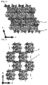
- FIGs. 2 to 4 are views of the crystal structure of H 2 NiP 2 O 7 as seen from an a-axis direction ( FIG. 2 ), a b-axis direction ( FIG. 3 ) and a c-axis direction ( FIG. 4 ).
- adjacent NiO 6 octahedra 21 share edges with each other; adjacent PO 4 tetrahedra 22 share apices with each other; and adjacent NiO 6 octahedra 21 and PO 4 tetrahedra 22 share apices. Therefore, it is clear that the H 2 NiP 2 O 7 has the three-dimensional framework.
- the method for synthesizing the H 2 NiP 2 O 7 is not particularly limited. An example of the synthesis method is described below.
- a nickel compound and a phosphoric acid compound are prepared.
- a mixture of the raw materials is dissolved in a predetermined acid to prepare a mixed solution.
- the heating temperature is preferably 200 to 250°C.
- the heating time is preferably about 3 to 7 days, for example.
- the mixed solution is further dried under reduced pressure for about 5 to 30 hours to absolutely remove water from the solution, thereby obtaining the H 2 NiP 2 O 7 .
- nickel compound examples include nickel(II) hydroxide (Ni(OH) 2 ), nickel (II) acetate (Ni(CH 3 CO 2 ) 2 ), nickel (II) nitrate (Ni(NO 3 ) 2 ), nickel (II) sulfate (NiSO 4 ), nickel (II) oxalate (NiC 2 O 4 ), nickel(II) chloride (NiCl 2 ) and hydrates thereof.
- Examples of the phosphoric acid compound include ammonium dihydrogenphosphate (NH 4 H 2 PO 4 ), phosphoric acid (H 3 PO 4 ), ammonium phosphate ((NH 4 ) 3 PO 4 ) and hydrates thereof.
- the above examples may be used alone or in combination of two or more kinds.
- the phosphoric acid compound the above examples may be used alone or in combination of two or more kinds.
- the H 2 NiP 2 O 7 may be used alone, or the H 2 NiP 2 O 7 may be used in combination with one or more different kinds of cathode active materials.
- the different kinds of cathode active materials include a compound obtained by substituting the Ni in the H 2 NiP 2 O 7 with a different element other than Ni, and nickel compounds such as ⁇ -type nickel hydroxide ( ⁇ -Ni(OH) 2 ).
- the different element occupies a part of the crystallographically equivalent sites in which nickel is the main occupying element.
- the different element include the first-row transition metal elements and the second-row transition metal elements.
- the amount of the different element substituted with the Ni is preferably 50 at% or less. If the amount is larger than 50 at%, there may be an increase in raw material cost.
- the different element is required to be able to have a stable valence in the air, and it is not required to be divalent.
- the content ratio of the H 2 NiP 2 O 7 in the cathode active material is not particularly limited. From the viewpoint of suppressing the decrease in battery voltage, it is preferably 60 to 100 mass% with respect to the total mass of the cathode active material.
- the content ratio of the cathode active material in the cathode active material layer is not particularly limited. It is preferably in a range of 60 to 100 mass% with respect to the total mass of the cathode active material layer.
- the cathode active material layer may contain the cathode active material only, or it may also contain an electroconductive material, a binder, etc., as needed.
- the electroconductive material is not particularly limited, as long as it can increase the electroconductivity of the cathode active material layer.
- the examples include compounds containing Co, such as CoO, Co, CoOOH, Co(OH) 2 , Co 2 O 3 and Co 3 O 4 , and carbon blacks such as acetylene black and Ketjen Black.
- the content ratio of the electroconductive material in the cathode active material layer varies depending on the type of the electroconductive material. It is generally in a range of 1 to 30 mass%.
- binder examples include polyvinylidene fluoride (PVdF), polytetrafluoroethylene (PTFE) and carboxymethyl cellulose (CMC).
- PVdF polyvinylidene fluoride
- PTFE polytetrafluoroethylene
- CMC carboxymethyl cellulose
- the content of the binder in the cathode active material layer is required to be an amount that is able to fix the cathode active material, etc. More preferably, it is as small as possible.
- the content ratio of the binder in the cathode active material layer is generally in a range of 1 to 10 mass%.
- the method for producing the cathode active material layer used in the present disclosure is not particularly limited.
- the examples include a method of mixing the above-mentioned materials for the cathode, such as the electroconductive material, and roll-pressing the mixture, and a method of applying a slurry that contains the above-mentioned materials for the cathode and a solvent.
- the solvent used to prepare the slurry include acetone, ethanol and N-methyl-2-pyrrolidone (NMP).
- NMP N-methyl-2-pyrrolidone
- the method for applying the slurry include a spraying method, a screen printing method, a gravure printing method, a die coating method, a doctor blade method and an ink-jet method.
- the cathode active material layer can be formed by applying the slurry to the below-described cathode current collector or a carrier film, drying the applied slurry and, as needed, roll-pressing and/or cutting the dried slurry.
- the thickness of the cathode active material layer varies depending on the intended use of the nickel hydrogen battery. It is preferably in the range of 10 to 250 ⁇ m.
- Examples of the material for the cathode current collector include aluminum, SUS, nickel, iron and titanium. Among them, nickel is preferred.
- Examples of the form of the cathode current collector include a foil form, a plate form and a mesh form. Among them, the mesh form is preferred.
- the thickness of the cathode current collector is not particularly limited. For example, it is preferably 10 to 1000 ⁇ m, particularly preferably 20 to 400 ⁇ m. Also, the below-described outer case may function as the cathode current collector.
- the cathode current collector may have a terminal that serves as a connection to the outside.
- the method for producing the cathode used in the present disclosure is not particularly limited, as long as it is a method by which the above-mentioned cathode can be obtained.
- the cathode active material layer may be pressed in order to increase electrode density.
- the anode contains at least the anode active material.
- the anode has the anode active material layer which contains at least the anode active material.
- the anode further has the anode current collector which collects current from the anode active material layer.
- the anode active material preferably contains at least one selected from the group consisting of a hydrogen storage alloy and hydrogen.
- the hydrogen storage alloy examples include AB-type hydrogen storage alloys (such as TiFe), AB2-type hydrogen storage alloys (such as ZrMn 2 ), AB5-type hydrogen storage alloys (such as LaNi 5 ), A2B-type hydrogen storage alloys (such as Mg 2 Ni) and solid solution-type hydrogen storage alloys (such as VTi).
- AB-type hydrogen storage alloys such as TiFe
- AB2-type hydrogen storage alloys such as ZrMn 2
- AB5-type hydrogen storage alloys such as LaNi 5
- A2B-type hydrogen storage alloys such as Mg 2 Ni
- solid solution-type hydrogen storage alloys such as VTi
- the form of the anode is not particularly limited.
- the examples include a foil form, a rod form and a particle form.
- the anode active material layer may contain the anode active material only. As needed, it contains at least one of an electroconductive material and a binder for fixing the anode active material.
- the anode active material layer can be a layer that contains only the anode active material.
- the anode active material layer can be a layer that contains the anode active material and the binder.
- the electroconductive material and the binder will not be described here since they are the same as the electroconductive material and the binder contained in the above-described cathode active material layer.
- the thickness of the anode active material layer is not particularly limited. For example, it is preferably in a range of 10 to 100 ⁇ m, particularly preferably in a range of 10 to 50 ⁇ m.
- the same materials as those for the above-described cathode current collector can be used.
- the form of the anode current collector the same forms as those for the above-described cathode current collector can be used.
- the thickness of the anode current collector is not particularly limited. For example, it is preferably 10 to 1000 ⁇ m, particularly preferably 20 to 400 ⁇ m.
- the below-described outer case may also function as the anode current collector.
- the anode current collector may have a terminal that serves as a connection to the outside.
- the method for producing the anode used in the present disclosure is not particularly limited, as long as it is a method by which the anode can be obtained. After the anode active material layer is formed, the anode active material layer may be pressed in order to increase electrode density.
- the electrolyte layer used in the present disclosure is present between the cathode and the anode, and it is in contact with the cathode and the anode.
- the electrolyte layer contains at least an electrolyte that enables ionic conduction between the cathode and the anode.
- electrolyte examples include a liquid electrolyte, a gel electrolyte and a solid electrolyte. They may be used alone or in combination of two or more kinds.
- liquid electrolyte examples include an aqueous liquid electrolyte and a non-aqueous liquid electrolyte. Of them, the aqueous liquid electrolyte is preferred.
- aqueous liquid electrolyte one containing an electrolyte salt and water is generally used.
- electrolyte salt examples include potassium hydroxide, lithium hydroxide, sodium hydroxide, rubidium hydroxide, cesium hydroxide, calcium hydroxide, strontium hydroxide, barium hydroxide, magnesium hydroxide and quaternary ammonium hydroxide. Of them, potassium hydroxide and sodium hydroxide are preferred.
- the concentration of the electrolyte salt in the aqueous liquid electrolyte is preferably 1 to 10 mol/L, more preferably 4 to 8 mol/L.
- concentration is less than 1 mol/L, electroconductivity decreases and sufficient battery capacity may not be obtained.
- concentration is more than 10 mol/L, the liquid electrolyte is likely to absorb carbon dioxide in the air, and carbonate may be produced. As a result, even in this case, electroconductivity decreases and sufficient battery capacity may not be obtained.
- non-aqueous liquid electrolyte one containing the electrolyte salt and a non-aqueous solvent is generally used.
- non-aqueous solvent examples include ethylene carbonate (EC), propylene carbonate (PC), butylene carbonate (BC), dimethyl carbonate (DMC), diethyl carbonate (DEC), ethyl methyl carbonate (EMC), ⁇ -butyrolactone, sulfolane, acetonitrile (AcN), dimethoxymethane, 1,2-dimethoxyethane (DME), 1,3-dimethoxypropane, diethyl ether, tetraethylene glycol dimethyl ether (TEGDME), tetrahydrofuran, 2-methyltetrahydrofuran, dimethylsulfoxide (DMSO) and mixtures thereof.
- EC ethylene carbonate
- PC propylene carbonate
- BC dimethyl carbonate
- DEC diethyl carbonate
- EMC ethyl methyl carbonate
- ⁇ -butyrolactone examples include sulfolane, acetonitrile (AcN),
- a mixed solvent of EC, DMC and EMC is particularly preferred.
- the gel electrolyte is generally a non-aqueous liquid electrolyte gelled by adding a polymer thereto.
- the gel electrolyte is obtained by gelling the above-described non-aqueous liquid electrolyte by adding a polymer such as polyethylene oxide, polypropylene oxide, polyacrylonitrile, polyvinylidene fluoride (PVdF), polyurethane, polyacrylate or cellulose thereto.
- a polymer such as polyethylene oxide, polypropylene oxide, polyacrylonitrile, polyvinylidene fluoride (PVdF), polyurethane, polyacrylate or cellulose thereto.
- solid electrolyte examples include a sulfide solid electrolyte and an oxide solid electrolyte. Conventionally-known solid electrolytes can be used as the solid electrolyte.
- the cathode and the anode can be insulated from each other by placing a separator, which is an insulating porous body, between the cathode and the anode and impregnating the separator with the liquid electrolyte.
- a separator which is an insulating porous body
- the separator include porous films such as a polyethylene porous film and a polypropylene porous film, and non-woven fabrics such as a resin non-woven fabric and a glass non-woven fabric.
- the nickel hydrogen battery of the present disclosure includes an outer case for housing the cathode, the anode, the electrolyte layer, etc.
- Concrete examples of the form of the outer case include a coin form, a flat plate form, a cylindrical form and a laminate form.
- the material for the outer case is not particularly limited, as long as it is stable in electrolytes.
- the examples include a metal body that contains at least one selected from the group consisting of Ni, Cr and Al, and resins such as polypropylene, polyethylene and acrylic resins.
- the outer case may be one in which only the surface of the outer body consists of a metal body, or one in which the whole outer case consists of a metal body.
- Nickel acetate tetrahydrate and 85% phosphoric acid were put in the Teflon (trademark) inner cylinder of an autoclave and mixed.
- Teflon trademark
- the mixture was heated at 230°C for 6 days.
- centrifugal separation was conducted on the mixture to collect precipitates.
- the precipitates were washed with ethanol.
- the precipitates were washed with ion-exchanged water. The washing was continued until the pH of a filtrate became neutral.
- the washed collected precipitates were dried under reduced pressure at 80°C for 12 hours, thereby obtaining a powder of H 2 NiP 2 O 7 .
- X-ray diffraction (XRD) measurement was conducted.
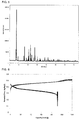
- the XRD measurement was conducted on the powder sample under an inert atmosphere. The results are shown in FIG. 5 .
- the conditions of the XRD measurement are as follows.
- the cathode active material has diffraction peaks at the following positions of diffraction angle 2 ⁇ : 12.44°, 21.35°, 26.05°, 27.84° and 32.53°. These peak positions may have a margin of error of about ⁇ 0.50° (particularly a range of ⁇ 0.30°, especially a range of ⁇ 0.10°) since there is a slight change in crystal lattice depending on material composition, etc.
- the crystal structure of the thus-obtained cathode active material (H 2 NiP 2 O 7 ) was identified by X-ray structural analysis.
- the crystal system and group of the cathode active material were determined by a direct method. Then, the crystal structure was identified by a real space method.
- the cathode active material has the crystal structure as shown in the above-described FIGs. 2 to 4 . That is, it was such a crystal structure that adjacent NiO 6 octahedra share edges with each other; adjacent PO 4 tetrahedra share apices with each other; and adjacent NiO 6 octahedra and PO 4 tetrahedra share apices.
- a foamed nickel (current collector) was impregnated with this composition, dried and then roll-pressed, thereby producing a working electrode.
- a foamed nickel (current collector) was impregnated with this composition, dried and then roll-pressed, thereby producing two counter electrodes.
- the working electrode was sandwiched between the two counter electrodes through non-woven fabric separators made of polyethylene-polypropylene.
- the resulting stack was pressed from both sides thereof with acrylic plates to fix the electrodes and the separators.
- Hg/HgO mercury oxide electrode
- the H 2 NiP 2 O 7 stably functions as the cathode active material of the nickel hydrogen battery. It is also clear that even after repeating the charge-discharge cycles, there is almost no change in the charge-discharge curves of the battery using the H 2 NiP 2 O 7 , and the battery operates quite stably. This is considered to be because, since the crystal structure of the H 2 NiP 2 O 7 is not a layered structure, there is almost no change in the crystal structure even after charging (including overcharging) the battery.
- Non-Patent Literature 3 shows a decrease in battery voltage after charging the battery (see figures 1 to 3 in Non-Patent Literature 3).
Landscapes
- Chemical & Material Sciences (AREA)
- Chemical Kinetics & Catalysis (AREA)
- Electrochemistry (AREA)
- General Chemical & Material Sciences (AREA)
- Inorganic Chemistry (AREA)
- Engineering & Computer Science (AREA)
- Manufacturing & Machinery (AREA)
- Organic Chemistry (AREA)
- Crystallography & Structural Chemistry (AREA)
- Battery Electrode And Active Subsutance (AREA)
- Secondary Cells (AREA)
Description
- The present disclosure relates to a nickel hydrogen battery.
- A nickel hydrogen battery is widely used in the fields of cellular phones, personal computers, electric tools, hybrid vehicles, electric vehicles, etc. Such a nickel hydrogen battery is used as a primary battery that can be discharged only once, and it is also used as a secondary battery (nickel hydrogen storage battery) that can be charged and discharged repeatedly.
- In the field of nickel hydrogen batteries, there has been an attempt to suppress a decrease in the capacity of nickel hydrogen batteries, focusing on electrolytes and electrode active materials. For example, in Patent Literature 1, it is disclosed to suppress a decrease in the capacity of a cylindrical nickel hydrogen storage, by defining the amount of zinc (Zn) added to a nickel (Ni) cathode and the alkali concentration of an alkaline electrolyte.
- Patent Literature 1: Japanese Patent Application Laid-Open No.
2012-069510 - Non-Patent Literature 1: Tao Yang, et al., "Inorganic Chemistry", 2007, 46, p. 2342-2344
- Non-Patent Literature 2: V. Pralong, et al., "Inorganic Chemistry", 2009, 48, p. 6835-6844
- Non-Patent Literature 3: Yuichi Sato, "SCIENCE REPORTS OF RESEARCH INSTITUTE FOR ENGINEERING, KANAGAWA UNIVERSITY, NO. 32", Research Institute for Engineering, Kanagawa University, issued on November 30, 2009, No. 32, p. 109-113
- However, a conventional nickel hydrogen battery that uses, as a cathode active material, a β-type nickel hydroxide (β-Ni(OH)2) having a layered structure as disclosed in Patent Literature 1, is problematic in that it cannot sufficiently suppress a decrease in battery voltage after charge.
- The present disclosure was achieved in light of the above circumstance. An object of the present disclosure is to provide a nickel hydrogen battery configured to be able to suppress a decrease in battery voltage.
- The nickel hydrogen battery of the present disclosure is characterized in that the battery includes: a cathode containing a cathode active material, an anode containing an anode active material, and an electrolyte layer in contact with the cathode and the anode, and the cathode active material contains H2NiP2O7 having a crystal structure comprising an NiO6 octahedron and a PO4 tetrahedron.
- In the nickel hydrogen battery of the present disclosure, it is preferable that the H2NiP2O7 includes a plurality of the NiO6 octahedra in the crystal structure, and the NiO6 octahedra share edges with the NiO6 octahedra adjacent thereto.
- In the nickel hydrogen battery of the present disclosure, it is preferable that the H2NiP2O7 includes a plurality of the PO4 tetrahedra in the crystal structure, and the PO4 tetrahedra share apices with the PO4 tetrahedra adjacent thereto.
- In the nickel hydrogen battery of the present disclosure, it is preferable that the H2NiP2O7 has a three-dimensional framework formed by sharing oxygen atoms contained in the NiO6 octahedra and the PO4 tetrahedra.
- In the nickel hydrogen battery of the present disclosure, it is preferable that the crystal structure is a structure belonging to space group P21/c.
- In the nickel hydrogen battery of the present disclosure, it is preferable that the anode active material contains at least one selected from hydrogen and a hydrogen storage alloy.
- According to the present disclosure, a nickel hydrogen battery configured to be able to suppress a decrease in battery voltage, can be provided.
- In the accompanying drawings,
-
FIG. 1 is a schematic sectional view of an embodiment of the battery of the present disclosure. -
FIG. 2 is a view of the crystal structure of H2NiP2O7 as seen from an a-axis direction. -
FIG. 3 is a view of the crystal structure of H2NiP2O7 as seen from a b-axis direction. -
FIG. 4 is a view of the crystal structure of H2NiP2O7 as seen from a c-axis direction. -
FIG. 5 shows the X-ray diffraction spectrum of H2NiP2O7. -
FIG. 6 is a view of the charge-discharge curves of Example 1 at the time of charge and discharge. -
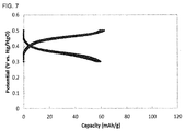
FIG. 7 is a view of the charge-discharge curves of Example 1 at the time of partial charge and discharge. - The nickel hydrogen battery of the present disclosure is characterized in that the battery includes: a cathode containing a cathode active material, an anode containing an anode active material, and an electrolyte layer in contact with the cathode and the anode, and the cathode active material contains H2NiP2O7 having a crystal structure comprising an NiO6 octahedron and a PO4 tetrahedron.
- In the case of a conventional nickel hydrogen battery that uses, as a cathode active material, β-Ni(OH)2 having a layered structure as disclosed in Patent Literature 1, once the battery is charged, the cathode active material exists as a β-type nickel oxyhydroxide (β-NiOOH) in which Ni has a valence of 3; moreover, once the battery is discharged, the cathode active material exists as a β-type nickel hydroxide (β-Ni(OH)2) in which Ni has a valence of 2. As just described, such a conventional nickel hydrogen battery can be charged and discharged by changing the cathode active material from the β-type nickel hydroxide to the β-type nickel oxyhydroxide and from the β-type nickel oxyhydroxide to the β-type nickel hydroxide, respectively.
- However, the conventional nickel hydrogen battery is problematic in that the battery voltage decreases after charge.
- For the conventional nickel hydrogen battery, it is considered that the reason for the decrease in battery voltage after charge is due to a γ-type nickel oxyhydroxide (γ-NiOOH) that is produced in the cathode by overcharging the battery (see Non-Patent Literature 3). For the γ-NiOOH produced by overcharging the battery, compared to β-NiOOH, the distance between the layers of the layered structure is wider and results in a large change in the crystal structure. Therefore, it is considered that the battery voltage decreases after charge.
- As a result of research to solve the above problem, the inventor of the present disclosure has found that the decrease in battery voltage after charge can be suppressed by the use of, in the cathode of the nickel hydrogen battery, the cathode active material which contains the H2NiP2O having the crystal structure comprising the NiO6 octahedron and the PO4 tetrahedron. Since the crystal structure of the H2NiP2O7 is not a layered structure, changes in the crystal structure made by charging (including overcharging) the battery are suppressed. As a result, the decrease in battery voltage after charge is suppressed.
- According to the present disclosure, the decrease in battery voltage by overcharging the battery can be suppressed; therefore, the nickel hydrogen battery can be used at a higher state of charge (SOC) than ever before.
- There is almost no change in the crystal structure of the H2NiP2O7, even after a shallow discharge is repeated. Therefore, according to the present disclosure, the occurrence of a so-called memory effect can be prevented or suppressed. Therefore, unlike conventional nickel hydrogen batteries, the nickel hydrogen battery of the present disclosure can prevent or suppress the occurrence of the memory effect, without any forced discharge, refresh discharge, full discharge, etc. The memory effect is a phenomenon wherein apparent capacity is decreased by repeating a shallow-depth discharge, and battery voltage decreases to the state of charge at the lower limit point of repeated discharges.
- The nickel hydrogen battery of the present disclosure may be either a primary or secondary battery. Preferably, it is a secondary battery.
-
FIG. 1 is a schematic sectional view of an embodiment of the nickel hydrogen battery of the present disclosure. The battery of the present disclosure is not limited to this embodiment only. - A
battery 100 has such a structure that an electrolyte layer 13 is disposed so as to be present between acathode 11 and ananode 12. Thecathode 11 has a cathodeactive material layer 14, which contains a cathode active material, and a cathodecurrent collector 15, which collects current from the cathodeactive material layer 14. Theanode 12 has an anodeactive material layer 16, which contains an anode active material, and an anodecurrent collector 17, which collects currents from the anodeactive material layer 16. - The cathode contains at least the cathode active material. In general, the cathode has the cathode active material layer which contains at least the cathode active material. As needed, the cathode further has the cathode current collector which collects current from the cathode active material layer.
- The cathode active material is not particularly limited, as long as it contains at least H2NiP2O7.
- The H2NiP2O7 used in the present disclosure has the crystal structure comprising the NiO6 octahedron and the PO4 tetrahedron.
- It is preferable that the H2NiP2O7 includes a plurality of the NiO6 octahedra in the crystal structure, and the NiO6 octahedra share edges with the NiO6 octahedra adjacent thereto. Because of this, electrons can be transferred between the NiO6's, and excellent electron conductivity can be expected. Therefore, a battery with higher output density can be provided.
- It is also preferable that the H2NiP2O7 includes a plurality of the PO4 tetrahedra in the crystal structure, and the PO4 tetrahedra share edges or apices with the PO4 tetrahedra adjacent thereto. It is more preferable that the PO4 tetrahedra share apices with the PO4 tetrahedra adjacent thereto. Because of this, the P atoms can firmly bind to the oxygen atoms, so that oxygen is less likely to be released from the cathode active material when the battery temperature is increased, and a battery that is able to operate more stably can be provided.
- It is also preferable that the H2NiP2O7 has a three-dimensional framework formed by the NiO6 octahedra and the PO4 tetrahedra by sharing the oxygen atoms contained in the NiO6 octahedra and the PO4 tetrahedra. Because of this, the NiO6 octahedra form the three-dimensional framework by the PO4, which has high binding force to oxygen, and the stability of the crystal structure is obtained.
- Also, it is particularly preferable that the H2NiP2O7 is such a compound that the edge-sharing NiO6 octahedra are contained in the crystal structure; the edge-sharing or apex-sharing PO4 tetrahedra are contained in the crystal structure; and the oxygen atoms of the NiO6 octahedra and the PO4 tetrahedra are shared to form the three-dimensional framework. It is more preferable that the H2NiP2O7 is such a compound that the edge-sharing NiO6 octahedra are contained in the crystal structure; the apex-sharing PO4 tetrahedra are contained in the crystal structure; and the oxygen atoms of the NiO6 octahedra and the PO4 tetrahedra are shared to form the three-dimensional framework.
- It is also preferable that the H2NiP2O7 has a crystal structure belonging to space group P21/c. The crystal structure and the space group can be determined by X-ray diffraction (XRD) measurement.
- The term "NiO6 octahedron" means a virtually formed octahedron having oxygen at its apices, in which an Ni atom is at the center of the octahedron and six oxygen atoms are coordinated so as to surround the Ni atom. The term "PO4 tetrahedron" means a virtually formed tetrahedron having oxygen at its apices, in which a P atom is at the center of the tetrahedron and four oxygen atoms are coordinated so as to surround the P atom.
- "Edge" means a virtual line formed by connecting oxygen atoms constituting a polyhedron such as octahedron or tetrahedron. That is, "edge-sharing" means such a state that adjacent polyhedra are bound by sharing two oxygen atoms. "Apex-sharing" means such a state that adjacent polyhedra are bound by sharing one oxygen atom.
- In the entire crystal structure of the H2NiP2O7, the percentage of the crystal structure comprising the NiO6 octahedron and the PO4 tetrahedron is not particularly limited. From the viewpoint of suppressing the decrease in battery voltage, it is preferably high. In particular, the percentage of the crystal structure is preferably 70 mass% or more, more preferably 90 mass% or more. The percentage of the crystal structure can be measured by X-ray diffraction with radiation, for example.
-
FIGs. 2 to 4 are views of the crystal structure of H2NiP2O7 as seen from an a-axis direction (FIG. 2 ), a b-axis direction (FIG. 3 ) and a c-axis direction (FIG. 4 ). - In the crystal structures shown in
FIGs. 2 to 4 , "21" means an NiO6 octahedron having Ni as the central element and oxygen as the apex elements, and "22" means a PO4 tetrahedron having P as the central element and oxygen as the apex elements. - As shown in
FIGs. 2 to 4 , adjacent NiO6 octahedra 21 share edges with each other; adjacent PO4 tetrahedra 22 share apices with each other; and adjacent NiO6 octahedra 21 and PO4 tetrahedra 22 share apices. Therefore, it is clear that the H2NiP2O7 has the three-dimensional framework. - The method for synthesizing the H2NiP2O7 is not particularly limited. An example of the synthesis method is described below.
- First, as raw materials, a nickel compound and a phosphoric acid compound are prepared.
- Next, a mixture of the raw materials is dissolved in a predetermined acid to prepare a mixed solution.
- Then, the mixed solution is appropriately heated. The heating temperature is preferably 200 to 250°C. The heating time is preferably about 3 to 7 days, for example.
- Then, in a drying oven at 50 to 90°C, the mixed solution is further dried under reduced pressure for about 5 to 30 hours to absolutely remove water from the solution, thereby obtaining the H2NiP2O7.
- Examples of the nickel compound include nickel(II) hydroxide (Ni(OH)2), nickel (II) acetate (Ni(CH3CO2)2), nickel (II) nitrate (Ni(NO3)2), nickel (II) sulfate (NiSO4), nickel (II) oxalate (NiC2O4), nickel(II) chloride (NiCl2) and hydrates thereof.
- Examples of the phosphoric acid compound include ammonium dihydrogenphosphate (NH4H2PO4), phosphoric acid (H3PO4), ammonium phosphate ((NH4)3PO4) and hydrates thereof.
- As the nickel compound, the above examples may be used alone or in combination of two or more kinds. As the phosphoric acid compound, the above examples may be used alone or in combination of two or more kinds.
- It is preferable to adjust the mixing ratio of the raw materials to the composition ratio of the elements in the H2NiP2O7.
- As the cathode active material, the H2NiP2O7 may be used alone, or the H2NiP2O7 may be used in combination with one or more different kinds of cathode active materials.
- Concrete examples of the different kinds of cathode active materials include a compound obtained by substituting the Ni in the H2NiP2O7 with a different element other than Ni, and nickel compounds such as β-type nickel hydroxide (β-Ni(OH)2). In the crystal structure constituting the complex oxide, the different element occupies a part of the crystallographically equivalent sites in which nickel is the main occupying element. Examples of the different element include the first-row transition metal elements and the second-row transition metal elements. The amount of the different element substituted with the Ni is preferably 50 at% or less. If the amount is larger than 50 at%, there may be an increase in raw material cost. The different element is required to be able to have a stable valence in the air, and it is not required to be divalent.
- The content ratio of the H2NiP2O7 in the cathode active material is not particularly limited. From the viewpoint of suppressing the decrease in battery voltage, it is preferably 60 to 100 mass% with respect to the total mass of the cathode active material.
- The content ratio of the cathode active material in the cathode active material layer is not particularly limited. It is preferably in a range of 60 to 100 mass% with respect to the total mass of the cathode active material layer.
- The cathode active material layer may contain the cathode active material only, or it may also contain an electroconductive material, a binder, etc., as needed.
- The electroconductive material is not particularly limited, as long as it can increase the electroconductivity of the cathode active material layer. The examples include compounds containing Co, such as CoO, Co, CoOOH, Co(OH)2, Co2O3 and Co3O4, and carbon blacks such as acetylene black and Ketjen Black. The content ratio of the electroconductive material in the cathode active material layer varies depending on the type of the electroconductive material. It is generally in a range of 1 to 30 mass%.
- Examples of the binder include polyvinylidene fluoride (PVdF), polytetrafluoroethylene (PTFE) and carboxymethyl cellulose (CMC). The content of the binder in the cathode active material layer is required to be an amount that is able to fix the cathode active material, etc. More preferably, it is as small as possible. The content ratio of the binder in the cathode active material layer is generally in a range of 1 to 10 mass%.
- The method for producing the cathode active material layer used in the present disclosure is not particularly limited. The examples include a method of mixing the above-mentioned materials for the cathode, such as the electroconductive material, and roll-pressing the mixture, and a method of applying a slurry that contains the above-mentioned materials for the cathode and a solvent. Examples of the solvent used to prepare the slurry include acetone, ethanol and N-methyl-2-pyrrolidone (NMP). Examples of the method for applying the slurry include a spraying method, a screen printing method, a gravure printing method, a die coating method, a doctor blade method and an ink-jet method. In particular, the cathode active material layer can be formed by applying the slurry to the below-described cathode current collector or a carrier film, drying the applied slurry and, as needed, roll-pressing and/or cutting the dried slurry.
- The thickness of the cathode active material layer varies depending on the intended use of the nickel hydrogen battery. It is preferably in the range of 10 to 250 µm.
- Examples of the material for the cathode current collector include aluminum, SUS, nickel, iron and titanium. Among them, nickel is preferred. Examples of the form of the cathode current collector include a foil form, a plate form and a mesh form. Among them, the mesh form is preferred.
- The thickness of the cathode current collector is not particularly limited. For example, it is preferably 10 to 1000 µm, particularly preferably 20 to 400 µm. Also, the below-described outer case may function as the cathode current collector.
- The cathode current collector may have a terminal that serves as a connection to the outside.
- The method for producing the cathode used in the present disclosure is not particularly limited, as long as it is a method by which the above-mentioned cathode can be obtained. After the cathode active material layer is formed, the cathode active material layer may be pressed in order to increase electrode density.
- The anode contains at least the anode active material. In general, the anode has the anode active material layer which contains at least the anode active material. As needed, the anode further has the anode current collector which collects current from the anode active material layer.
- The anode active material preferably contains at least one selected from the group consisting of a hydrogen storage alloy and hydrogen.
- Examples of the hydrogen storage alloy include AB-type hydrogen storage alloys (such as TiFe), AB2-type hydrogen storage alloys (such as ZrMn2), AB5-type hydrogen storage alloys (such as LaNi5), A2B-type hydrogen storage alloys (such as Mg2Ni) and solid solution-type hydrogen storage alloys (such as VTi).
- The form of the anode is not particularly limited. The examples include a foil form, a rod form and a particle form.
- The anode active material layer may contain the anode active material only. As needed, it contains at least one of an electroconductive material and a binder for fixing the anode active material. For example, when the anode active material is in a plate form, foil form or the like, the anode active material layer can be a layer that contains only the anode active material. On the other hand, when the anode active material is in a powder form, the anode active material layer can be a layer that contains the anode active material and the binder. The electroconductive material and the binder will not be described here since they are the same as the electroconductive material and the binder contained in the above-described cathode active material layer.
- The thickness of the anode active material layer is not particularly limited. For example, it is preferably in a range of 10 to 100 µm, particularly preferably in a range of 10 to 50 µm.
- As the material for the anode current collector, the same materials as those for the above-described cathode current collector can be used. As the form of the anode current collector, the same forms as those for the above-described cathode current collector can be used. The thickness of the anode current collector is not particularly limited. For example, it is preferably 10 to 1000 µm, particularly preferably 20 to 400 µm. The below-described outer case may also function as the anode current collector.
- The anode current collector may have a terminal that serves as a connection to the outside.
- The method for producing the anode used in the present disclosure is not particularly limited, as long as it is a method by which the anode can be obtained. After the anode active material layer is formed, the anode active material layer may be pressed in order to increase electrode density.
- The electrolyte layer used in the present disclosure is present between the cathode and the anode, and it is in contact with the cathode and the anode.
- The electrolyte layer contains at least an electrolyte that enables ionic conduction between the cathode and the anode.
- Examples of the electrolyte include a liquid electrolyte, a gel electrolyte and a solid electrolyte. They may be used alone or in combination of two or more kinds.
- Examples of the liquid electrolyte includes an aqueous liquid electrolyte and a non-aqueous liquid electrolyte. Of them, the aqueous liquid electrolyte is preferred.
- As the aqueous liquid electrolyte, one containing an electrolyte salt and water is generally used.
- Examples of the electrolyte salt include potassium hydroxide, lithium hydroxide, sodium hydroxide, rubidium hydroxide, cesium hydroxide, calcium hydroxide, strontium hydroxide, barium hydroxide, magnesium hydroxide and quaternary ammonium hydroxide. Of them, potassium hydroxide and sodium hydroxide are preferred.
- The concentration of the electrolyte salt in the aqueous liquid electrolyte is preferably 1 to 10 mol/L, more preferably 4 to 8 mol/L. When the concentration is less than 1 mol/L, electroconductivity decreases and sufficient battery capacity may not be obtained. On the other hand, when the concentration is more than 10 mol/L, the liquid electrolyte is likely to absorb carbon dioxide in the air, and carbonate may be produced. As a result, even in this case, electroconductivity decreases and sufficient battery capacity may not be obtained.
- As the non-aqueous liquid electrolyte, one containing the electrolyte salt and a non-aqueous solvent is generally used.
- Examples of the non-aqueous solvent include ethylene carbonate (EC), propylene carbonate (PC), butylene carbonate (BC), dimethyl carbonate (DMC), diethyl carbonate (DEC), ethyl methyl carbonate (EMC), γ-butyrolactone, sulfolane, acetonitrile (AcN), dimethoxymethane, 1,2-dimethoxyethane (DME), 1,3-dimethoxypropane, diethyl ether, tetraethylene glycol dimethyl ether (TEGDME), tetrahydrofuran, 2-methyltetrahydrofuran, dimethylsulfoxide (DMSO) and mixtures thereof.
- From the viewpoint of securing high dielectric constant and low viscosity, preferred is a mixture of a cyclic carbonate compound having high dielectric constant and high viscosity, such as EC, PC or BC, and a chain carbonate compound having low dielectric constant and low viscosity, such as DMC, DEC or EMC. Particularly preferred is a mixed solvent of EC, DMC and EMC.
- The gel electrolyte is generally a non-aqueous liquid electrolyte gelled by adding a polymer thereto.
- The gel electrolyte is obtained by gelling the above-described non-aqueous liquid electrolyte by adding a polymer such as polyethylene oxide, polypropylene oxide, polyacrylonitrile, polyvinylidene fluoride (PVdF), polyurethane, polyacrylate or cellulose thereto.
- Examples of the solid electrolyte include a sulfide solid electrolyte and an oxide solid electrolyte. Conventionally-known solid electrolytes can be used as the solid electrolyte.
- When the liquid electrolyte is used as the electrolyte, the cathode and the anode can be insulated from each other by placing a separator, which is an insulating porous body, between the cathode and the anode and impregnating the separator with the liquid electrolyte. Examples of the separator include porous films such as a polyethylene porous film and a polypropylene porous film, and non-woven fabrics such as a resin non-woven fabric and a glass non-woven fabric.
- In general, the nickel hydrogen battery of the present disclosure includes an outer case for housing the cathode, the anode, the electrolyte layer, etc. Concrete examples of the form of the outer case include a coin form, a flat plate form, a cylindrical form and a laminate form.
- The material for the outer case is not particularly limited, as long as it is stable in electrolytes. The examples include a metal body that contains at least one selected from the group consisting of Ni, Cr and Al, and resins such as polypropylene, polyethylene and acrylic resins. When the outer case is a metal body, the outer case may be one in which only the surface of the outer body consists of a metal body, or one in which the whole outer case consists of a metal body.
- Nickel acetate tetrahydrate and 85% phosphoric acid were put in the Teflon (trademark) inner cylinder of an autoclave and mixed. In the autoclave, using an oil bath, the mixture was heated at 230°C for 6 days. Then, centrifugal separation was conducted on the mixture to collect precipitates. The precipitates were washed with ethanol. In addition, the precipitates were washed with ion-exchanged water. The washing was continued until the pH of a filtrate became neutral. The washed collected precipitates were dried under reduced pressure at 80°C for 12 hours, thereby obtaining a powder of H2NiP2O7.
- Using the thus-obtained cathode active material powder, X-ray diffraction (XRD) measurement was conducted. The XRD measurement was conducted on the powder sample under an inert atmosphere. The results are shown in
FIG. 5 . - The conditions of the XRD measurement are as follows.
- X-ray diffractometer: "Ultima IV" manufactured by Rigaku Corporation
- X-ray source: CuKα radiation
- Tube voltage-tube current: 40 kV - 40 mA
- Step width: 0.01 deg
- Measurement rate: 1°/min
- Detector: "D/tex Ultra" manufactured by Rigaku Corporation
- As shown in
FIG. 5 , as a result of the X-ray diffraction with CuKα radiation, it was confirmed that the cathode active material has diffraction peaks at the following positions of diffraction angle 2θ: 12.44°, 21.35°, 26.05°, 27.84° and 32.53°. These peak positions may have a margin of error of about ±0.50° (particularly a range of ±0.30°, especially a range of ±0.10°) since there is a slight change in crystal lattice depending on material composition, etc. - The crystal structure of the thus-obtained cathode active material (H2NiP2O7) was identified by X-ray structural analysis.
- Based on diffraction patterns obtained by the XRD, the crystal system and group of the cathode active material were determined by a direct method. Then, the crystal structure was identified by a real space method.
- As a result, it was confirmed that the cathode active material has the crystal structure as shown in the above-described
FIGs. 2 to 4 . That is, it was such a crystal structure that adjacent NiO6 octahedra share edges with each other; adjacent PO4 tetrahedra share apices with each other; and adjacent NiO6 octahedra and PO4tetrahedra share apices. - A slurry composition was produced by mixing, with NMP, the thus-obtained H2NiP2O7 powder, CoO and PVdF at a solid content mass ratio of H2NiP2O7 powder/CoO/PVdF = 85/10/5. A foamed nickel (current collector) was impregnated with this composition, dried and then roll-pressed, thereby producing a working electrode.
- A slurry composition was produced by mixing, with pure water, a hydrogen storage alloy, carboxymethyl cellulose (CMC) and PVA at a solid content mass ratio of hydrogen storage alloy/CMC/PVA = 98.4/0.8/0.8. A foamed nickel (current collector) was impregnated with this composition, dried and then roll-pressed, thereby producing two counter electrodes.
- The working electrode was sandwiched between the two counter electrodes through non-woven fabric separators made of polyethylene-polypropylene. The resulting stack was pressed from both sides thereof with acrylic plates to fix the electrodes and the separators.
- In addition, a mercury oxide electrode (Hg/HgO) was used as a reference electrode.
- As a liquid electrolyte, 6 mol/L KOH aqueous solution was used.
- Using the evaluation cell thus produced, charge and discharge of the cell were conducted at a charge-discharge current of 23 mA/g (corresponding to C/10). Ten cycles of charge of the cell for 14 hours until the cell entered a fully overcharged state and discharge of the cell to 0.1 V (vs. Hg/HgO) were conducted under room temperature environment. The result of the charge-discharge test is shown in
FIG. 6 . - Another evaluation cell was produced by the same method as the above "[Charge-discharge test 1]". Partial charge and discharge of the cell were conducted at a charge-discharge current of 23 mA/g (corresponding to C/10). Ten cycles of charge of the cell to 0.5 V (vs. Hg/HgO) and discharge of the cell to 0.3 V (vs. Hg/HgO) (the discharge of the cell was stopped when the cell was in such a state that there was some capacity left) were conducted under room temperature environment. The result of the charge-discharge test 2 is shown in
FIG. 7 . - As shown by the charge-discharge curves in
FIGs. 6 and7 , it is clear that the H2NiP2O7 stably functions as the cathode active material of the nickel hydrogen battery. It is also clear that even after repeating the charge-discharge cycles, there is almost no change in the charge-discharge curves of the battery using the H2NiP2O7, and the battery operates quite stably. This is considered to be because, since the crystal structure of the H2NiP2O7 is not a layered structure, there is almost no change in the crystal structure even after charging (including overcharging) the battery. - The nickel-cadmium battery as disclosed in Non-Patent Literature 3, in which a β-type nickel hydroxide is used in the cathode, shows a decrease in battery voltage after charging the battery (see
figures 1 to 3 in Non-Patent Literature 3). - Meanwhile, as shown by the charge-discharge curves in
FIG. 6 , in the case of the nickel hydrogen battery in which the H2NiP2O7 is used in the cathode, it is clear that there is almost no change in battery voltage even after charge (including overcharge) and discharge of the battery were repeated. Therefore, it is clear that a decrease in battery voltage after charge can be suppressed according to the present disclosure. - Also, as shown by the charge-discharge curves in
FIG. 7 , in the case of the nickel hydrogen battery in which the H2NiP2O7 is used in the cathode, there is almost no change in battery voltage even after shallow discharge of the battery was repeated. Therefore, it is clear that the occurrence of a so-called memory effect is suppressed according to the present disclosure. -
- 11.
- Cathode
- 12.
- Anode
- 13.
- Electrolyte layer
- 14.
- Cathode active material layer
- 15.
- Cathode current collector
- 16.
- Anode active material layer
- 17.
- Anode current collector
- 21.
- NiO6 octahedron
- 22.
- PO4 tetrahedron
- 100.
- Battery
Claims (6)
- A nickel hydrogen battery(100),
wherein the battery(100) comprises:a cathode(11) containing a cathode active material,an anode(12) containing an anode active material, andan electrolyte layer(13) in contact with thecathode(11) and the anode(12), andwherein the cathode active material contains H2NiP2O7 having a crystal structure comprising an NiO6 octahedron(21) and a PO4 tetrahedron(22). - The nickel hydrogen battery(100) according to claim 1, wherein the H2NiP2O7 comprises a plurality of NiO6 octahedra(21) in the crystal structure, and the NiO6 octahedra(21) share edges with the NiO6 octahedra(21) adjacent thereto.
- The nickel hydrogen battery(100) according to claim 1 or 2, wherein the H2NiP2O7 comprises a plurality of PO4 tetrahedra(22) in the crystal structure, and the PO4 tetrahedra (22) share apices with the PO4 tetrahedra(22) adjacent thereto.
- The nickel hydrogen battery(100) according to any one of claims 1 to 3, wherein the H2NiP2O7 has a three-dimensional framework formed by sharing oxygen atoms contained in NiO6 octahedra(21) and PO4 tetrahedra(22).
- The nickel hydrogen battery(100) according to any one of claims 1 to 4, wherein the crystal structure is a structure belonging to space group P21/c.
- The nickel hydrogen battery(100) according to any one of claims 1 to 5, wherein the anode active material contains at least one selected from hydrogen and a hydrogen storage alloy.
Applications Claiming Priority (1)
| Application Number | Priority Date | Filing Date | Title |
|---|---|---|---|
| JP2015163406A JP6229698B2 (en) | 2015-08-21 | 2015-08-21 | Nickel metal hydride battery |
Publications (2)
| Publication Number | Publication Date |
|---|---|
| EP3133677A1 true EP3133677A1 (en) | 2017-02-22 |
| EP3133677B1 EP3133677B1 (en) | 2018-01-24 |
Family
ID=56737982
Family Applications (1)
| Application Number | Title | Priority Date | Filing Date |
|---|---|---|---|
| EP16184497.2A Active EP3133677B1 (en) | 2015-08-21 | 2016-08-17 | Nickel hydrogen battery |
Country Status (5)
| Country | Link |
|---|---|
| US (1) | US9985288B2 (en) |
| EP (1) | EP3133677B1 (en) |
| JP (1) | JP6229698B2 (en) |
| KR (1) | KR101823257B1 (en) |
| CN (1) | CN106469833B (en) |
Families Citing this family (1)
| Publication number | Priority date | Publication date | Assignee | Title |
|---|---|---|---|---|
| JP7221237B2 (en) * | 2020-04-27 | 2023-02-13 | プライムアースEvエナジー株式会社 | Method for manufacturing secondary battery |
Citations (1)
| Publication number | Priority date | Publication date | Assignee | Title |
|---|---|---|---|---|
| JP2012069510A (en) | 2010-08-27 | 2012-04-05 | Sanyo Electric Co Ltd | Cylindrical nickel-hydrogen storage battery |
Family Cites Families (10)
| Publication number | Priority date | Publication date | Assignee | Title |
|---|---|---|---|---|
| JP3773694B2 (en) * | 1999-04-07 | 2006-05-10 | 三洋電機株式会社 | Manufacturing method of nickel metal hydride storage battery |
| US20010026891A1 (en) * | 2000-03-28 | 2001-10-04 | Yoshitaka Dansui | Nickel positive electrode active material and nickel metal hydride storage battery |
| US7008566B2 (en) * | 2003-04-08 | 2006-03-07 | Valence Technology, Inc. | Oligo phosphate-based electrode active materials and methods of making same |
| FR2864348B1 (en) * | 2003-12-18 | 2006-03-10 | Commissariat Energie Atomique | LITHIUM ACCUMULATOR HAVING BOTH ELECTRICAL POTENTIAL AND HIGH LTHIUM INSERTION CAPABILITY. |
| JP2006040698A (en) * | 2004-07-27 | 2006-02-09 | Toyota Motor Corp | Positive electrode for alkaline storage battery and alkaline storage battery |
| JP4736372B2 (en) * | 2004-07-30 | 2011-07-27 | トヨタ自動車株式会社 | Positive electrode active material for alkaline storage battery, positive electrode for alkaline storage battery, and alkaline storage battery |
| KR100814881B1 (en) * | 2006-11-24 | 2008-03-18 | 삼성에스디아이 주식회사 | Battery active material, electrode and battery comprising same |
| JP5352358B2 (en) | 2009-07-03 | 2013-11-27 | シャープ株式会社 | Positive electrode active material for non-aqueous electrolyte secondary battery and non-aqueous electrolyte secondary battery |
| CN102803134B (en) * | 2009-12-04 | 2015-09-30 | 国立大学法人东京大学 | Pyrophosphate salt compound and manufacture method thereof |
| JP2012146630A (en) | 2010-12-21 | 2012-08-02 | Univ Of Tsukuba | Positive electrode active material, method for manufacturing the same, and lithium ion secondary battery |
-
2015
- 2015-08-21 JP JP2015163406A patent/JP6229698B2/en active Active
-
2016
- 2016-08-11 KR KR1020160102389A patent/KR101823257B1/en active Active
- 2016-08-12 US US15/235,615 patent/US9985288B2/en active Active
- 2016-08-15 CN CN201610666468.3A patent/CN106469833B/en active Active
- 2016-08-17 EP EP16184497.2A patent/EP3133677B1/en active Active
Patent Citations (1)
| Publication number | Priority date | Publication date | Assignee | Title |
|---|---|---|---|---|
| JP2012069510A (en) | 2010-08-27 | 2012-04-05 | Sanyo Electric Co Ltd | Cylindrical nickel-hydrogen storage battery |
Non-Patent Citations (5)
| Title |
|---|
| GAO X ET AL: "Structure, morphology and electrochemical performance of Zn-doped [Ni4Al(OH)10]OH", JOURNAL OF POWER SOURCES, ELSEVIER SA, CH, vol. 191, no. 2, 15 June 2009 (2009-06-15), pages 662 - 668, XP026100448, ISSN: 0378-7753, [retrieved on 20090304], DOI: 10.1016/J.JPOWSOUR.2009.02.055 * |
| TAO YANG ET AL., INORGANIC CHEMISTRY, vol. 46, 2007, pages 2342 - 2344 |
| V. PRALONG ET AL., INORGANIC CHEMISTRY, vol. 48, 2009, pages 6835 - 6844 |
| V. PRALONG ET AL: "Transition metal hydrogenophosphates: a potential source of new protonic and lithium conductors", JOURNAL OF MATERIALS CHEMISTRY, vol. 21, no. 33, 1 July 2011 (2011-07-01), GB, pages 12188, XP055302467, ISSN: 0959-9428, DOI: 10.1039/c1jm11046b * |
| YUICHI SATO: "SCIENCE REPORTS OF RESEARCH INSTITUTE FOR ENGINEERING", 30 November 2009, RESEARCH INSTITUTE FOR ENGINEERING, pages: 109 - 113 |
Also Published As
| Publication number | Publication date |
|---|---|
| US9985288B2 (en) | 2018-05-29 |
| KR101823257B1 (en) | 2018-01-29 |
| KR20170022888A (en) | 2017-03-02 |
| US20170054151A1 (en) | 2017-02-23 |
| CN106469833A (en) | 2017-03-01 |
| JP6229698B2 (en) | 2017-11-15 |
| CN106469833B (en) | 2019-03-08 |
| EP3133677B1 (en) | 2018-01-24 |
| JP2017041393A (en) | 2017-02-23 |
Similar Documents
| Publication | Publication Date | Title |
|---|---|---|
| US9083062B2 (en) | Battery packs for vehicles and high capacity pouch secondary batteries for incorporation into compact battery packs | |
| CA2158242C (en) | High voltage insertion compounds for lithium batteries | |
| JP5910627B2 (en) | Secondary battery | |
| KR101754800B1 (en) | Cathode, preparation method thereof, and lithium battery containing the same | |
| KR101670327B1 (en) | Composite cathode materials with controlled irreversible capacity loss for lithium ion batteries | |
| JP5099168B2 (en) | Lithium ion secondary battery | |
| US9577247B2 (en) | Positive electrode active material for nonaqueous electrolyte secondary battery, and nonaqueous electrolyte secondary battery | |
| KR102770494B1 (en) | Active Material For Zinc-based Secondary Battery And Secondary Battery Having The Same | |
| KR20140067508A (en) | Positive active material for lithium secondary battery, method of preparing the same, and lithium secondary battery using the same | |
| JP2020123460A (en) | Pre-doping material, positive electrode including pre-doping material, and method for producing non-aqueous electrolyte secondary battery including positive electrode thereof, and method for producing metal oxide | |
| EP3627611A1 (en) | Zinc salts which can be used as liquid electrolyte of zinc-ion battery | |
| EP4489122B1 (en) | Positive electrode active material, method for producing same and nonaqueous electrolyte secondary battery | |
| JP6800322B2 (en) | Positive electrode active material for potassium secondary batteries, potassium secondary batteries containing this | |
| EP3627607A1 (en) | Electrode material for zinc secondary batteries | |
| WO2022182313A2 (en) | Development of new air-stable o3-naxmo2 type layered metal oxides for sodium ion batteries | |
| US12206091B2 (en) | Lithium molybdate anode material | |
| JP2021082537A (en) | Magnesium ion secondary battery, positive electrode active material for magnesium ion secondary battery and positive electrode for magnesium ion secondary battery | |
| WO2020255489A1 (en) | Anode material, anode and battery cell | |
| JP7742546B2 (en) | Non-aqueous magnesium battery | |
| Sun et al. | Effectively enhance high voltage stability of LiNi1/3Co1/3Mn1/3O2 cathode material with excellent energy density via La2O3 surface modified | |
| EP3133677B1 (en) | Nickel hydrogen battery | |
| KR101909317B1 (en) | Cathode active material for lithium secondary battery and method of making the same | |
| KR101983608B1 (en) | Positive active material for potassium secondary batteries and potassium secondary batteries | |
| US20200106096A1 (en) | Positive active material for potassium secondary battery and potassium secondary battery including the same | |
| JP6911545B2 (en) | Negative electrode and non-aqueous electrolyte power storage element |
Legal Events
| Date | Code | Title | Description |
|---|---|---|---|
| PUAI | Public reference made under article 153(3) epc to a published international application that has entered the european phase |
Free format text: ORIGINAL CODE: 0009012 |
|
| STAA | Information on the status of an ep patent application or granted ep patent |
Free format text: STATUS: REQUEST FOR EXAMINATION WAS MADE |
|
| 17P | Request for examination filed |
Effective date: 20160817 |
|
| AK | Designated contracting states |
Kind code of ref document: A1 Designated state(s): AL AT BE BG CH CY CZ DE DK EE ES FI FR GB GR HR HU IE IS IT LI LT LU LV MC MK MT NL NO PL PT RO RS SE SI SK SM TR |
|
| AX | Request for extension of the european patent |
Extension state: BA ME |
|
| RIC1 | Information provided on ipc code assigned before grant |
Ipc: H01M 10/34 20060101ALI20170627BHEP Ipc: C01B 25/42 20060101ALI20170627BHEP Ipc: H01M 4/58 20100101ALI20170627BHEP Ipc: H01M 4/24 20060101AFI20170627BHEP Ipc: H01M 4/02 20060101ALN20170627BHEP |
|
| GRAP | Despatch of communication of intention to grant a patent |
Free format text: ORIGINAL CODE: EPIDOSNIGR1 |
|
| STAA | Information on the status of an ep patent application or granted ep patent |
Free format text: STATUS: GRANT OF PATENT IS INTENDED |
|
| INTG | Intention to grant announced |
Effective date: 20170821 |
|
| RIC1 | Information provided on ipc code assigned before grant |
Ipc: C01B 25/42 20060101ALI20170804BHEP Ipc: H01M 10/34 20060101ALI20170804BHEP Ipc: H01M 4/24 20060101AFI20170804BHEP Ipc: H01M 4/58 20100101ALI20170804BHEP Ipc: H01M 4/02 20060101ALN20170804BHEP |
|
| GRAS | Grant fee paid |
Free format text: ORIGINAL CODE: EPIDOSNIGR3 |
|
| GRAA | (expected) grant |
Free format text: ORIGINAL CODE: 0009210 |
|
| STAA | Information on the status of an ep patent application or granted ep patent |
Free format text: STATUS: THE PATENT HAS BEEN GRANTED |
|
| AK | Designated contracting states |
Kind code of ref document: B1 Designated state(s): AL AT BE BG CH CY CZ DE DK EE ES FI FR GB GR HR HU IE IS IT LI LT LU LV MC MK MT NL NO PL PT RO RS SE SI SK SM TR |
|
| REG | Reference to a national code |
Ref country code: GB Ref legal event code: FG4D |
|
| REG | Reference to a national code |
Ref country code: CH Ref legal event code: EP |
|
| REG | Reference to a national code |
Ref country code: AT Ref legal event code: REF Ref document number: 966253 Country of ref document: AT Kind code of ref document: T Effective date: 20180215 |
|
| REG | Reference to a national code |
Ref country code: IE Ref legal event code: FG4D |
|
| REG | Reference to a national code |
Ref country code: DE Ref legal event code: R096 Ref document number: 602016001452 Country of ref document: DE |
|
| REG | Reference to a national code |
Ref country code: NL Ref legal event code: MP Effective date: 20180124 |
|
| REG | Reference to a national code |
Ref country code: DE Ref legal event code: R084 Ref document number: 602016001452 Country of ref document: DE |
|
| REG | Reference to a national code |
Ref country code: LT Ref legal event code: MG4D |
|
| REG | Reference to a national code |
Ref country code: AT Ref legal event code: MK05 Ref document number: 966253 Country of ref document: AT Kind code of ref document: T Effective date: 20180124 |
|
| REG | Reference to a national code |
Ref country code: GB Ref legal event code: 746 Effective date: 20180530 |
|
| PG25 | Lapsed in a contracting state [announced via postgrant information from national office to epo] |
Ref country code: NL Free format text: LAPSE BECAUSE OF FAILURE TO SUBMIT A TRANSLATION OF THE DESCRIPTION OR TO PAY THE FEE WITHIN THE PRESCRIBED TIME-LIMIT Effective date: 20180124 |
|
| REG | Reference to a national code |
Ref country code: FR Ref legal event code: PLFP Year of fee payment: 3 |
|
| PG25 | Lapsed in a contracting state [announced via postgrant information from national office to epo] |
Ref country code: NO Free format text: LAPSE BECAUSE OF FAILURE TO SUBMIT A TRANSLATION OF THE DESCRIPTION OR TO PAY THE FEE WITHIN THE PRESCRIBED TIME-LIMIT Effective date: 20180424 Ref country code: FI Free format text: LAPSE BECAUSE OF FAILURE TO SUBMIT A TRANSLATION OF THE DESCRIPTION OR TO PAY THE FEE WITHIN THE PRESCRIBED TIME-LIMIT Effective date: 20180124 Ref country code: HR Free format text: LAPSE BECAUSE OF FAILURE TO SUBMIT A TRANSLATION OF THE DESCRIPTION OR TO PAY THE FEE WITHIN THE PRESCRIBED TIME-LIMIT Effective date: 20180124 Ref country code: CY Free format text: LAPSE BECAUSE OF FAILURE TO SUBMIT A TRANSLATION OF THE DESCRIPTION OR TO PAY THE FEE WITHIN THE PRESCRIBED TIME-LIMIT Effective date: 20180124 Ref country code: LT Free format text: LAPSE BECAUSE OF FAILURE TO SUBMIT A TRANSLATION OF THE DESCRIPTION OR TO PAY THE FEE WITHIN THE PRESCRIBED TIME-LIMIT Effective date: 20180124 Ref country code: ES Free format text: LAPSE BECAUSE OF FAILURE TO SUBMIT A TRANSLATION OF THE DESCRIPTION OR TO PAY THE FEE WITHIN THE PRESCRIBED TIME-LIMIT Effective date: 20180124 |
|
| PG25 | Lapsed in a contracting state [announced via postgrant information from national office to epo] |
Ref country code: BG Free format text: LAPSE BECAUSE OF FAILURE TO SUBMIT A TRANSLATION OF THE DESCRIPTION OR TO PAY THE FEE WITHIN THE PRESCRIBED TIME-LIMIT Effective date: 20180424 Ref country code: PL Free format text: LAPSE BECAUSE OF FAILURE TO SUBMIT A TRANSLATION OF THE DESCRIPTION OR TO PAY THE FEE WITHIN THE PRESCRIBED TIME-LIMIT Effective date: 20180124 Ref country code: GR Free format text: LAPSE BECAUSE OF FAILURE TO SUBMIT A TRANSLATION OF THE DESCRIPTION OR TO PAY THE FEE WITHIN THE PRESCRIBED TIME-LIMIT Effective date: 20180425 Ref country code: RS Free format text: LAPSE BECAUSE OF FAILURE TO SUBMIT A TRANSLATION OF THE DESCRIPTION OR TO PAY THE FEE WITHIN THE PRESCRIBED TIME-LIMIT Effective date: 20180124 Ref country code: LV Free format text: LAPSE BECAUSE OF FAILURE TO SUBMIT A TRANSLATION OF THE DESCRIPTION OR TO PAY THE FEE WITHIN THE PRESCRIBED TIME-LIMIT Effective date: 20180124 Ref country code: SE Free format text: LAPSE BECAUSE OF FAILURE TO SUBMIT A TRANSLATION OF THE DESCRIPTION OR TO PAY THE FEE WITHIN THE PRESCRIBED TIME-LIMIT Effective date: 20180124 Ref country code: IS Free format text: LAPSE BECAUSE OF FAILURE TO SUBMIT A TRANSLATION OF THE DESCRIPTION OR TO PAY THE FEE WITHIN THE PRESCRIBED TIME-LIMIT Effective date: 20180524 Ref country code: AT Free format text: LAPSE BECAUSE OF FAILURE TO SUBMIT A TRANSLATION OF THE DESCRIPTION OR TO PAY THE FEE WITHIN THE PRESCRIBED TIME-LIMIT Effective date: 20180124 |
|
| REG | Reference to a national code |
Ref country code: DE Ref legal event code: R097 Ref document number: 602016001452 Country of ref document: DE |
|
| PG25 | Lapsed in a contracting state [announced via postgrant information from national office to epo] |
Ref country code: IT Free format text: LAPSE BECAUSE OF FAILURE TO SUBMIT A TRANSLATION OF THE DESCRIPTION OR TO PAY THE FEE WITHIN THE PRESCRIBED TIME-LIMIT Effective date: 20180124 Ref country code: EE Free format text: LAPSE BECAUSE OF FAILURE TO SUBMIT A TRANSLATION OF THE DESCRIPTION OR TO PAY THE FEE WITHIN THE PRESCRIBED TIME-LIMIT Effective date: 20180124 Ref country code: AL Free format text: LAPSE BECAUSE OF FAILURE TO SUBMIT A TRANSLATION OF THE DESCRIPTION OR TO PAY THE FEE WITHIN THE PRESCRIBED TIME-LIMIT Effective date: 20180124 |
|
| PG25 | Lapsed in a contracting state [announced via postgrant information from national office to epo] |
Ref country code: CZ Free format text: LAPSE BECAUSE OF FAILURE TO SUBMIT A TRANSLATION OF THE DESCRIPTION OR TO PAY THE FEE WITHIN THE PRESCRIBED TIME-LIMIT Effective date: 20180124 Ref country code: SK Free format text: LAPSE BECAUSE OF FAILURE TO SUBMIT A TRANSLATION OF THE DESCRIPTION OR TO PAY THE FEE WITHIN THE PRESCRIBED TIME-LIMIT Effective date: 20180124 Ref country code: SM Free format text: LAPSE BECAUSE OF FAILURE TO SUBMIT A TRANSLATION OF THE DESCRIPTION OR TO PAY THE FEE WITHIN THE PRESCRIBED TIME-LIMIT Effective date: 20180124 Ref country code: DK Free format text: LAPSE BECAUSE OF FAILURE TO SUBMIT A TRANSLATION OF THE DESCRIPTION OR TO PAY THE FEE WITHIN THE PRESCRIBED TIME-LIMIT Effective date: 20180124 |
|
| PLBE | No opposition filed within time limit |
Free format text: ORIGINAL CODE: 0009261 |
|
| STAA | Information on the status of an ep patent application or granted ep patent |
Free format text: STATUS: NO OPPOSITION FILED WITHIN TIME LIMIT |
|
| 26N | No opposition filed |
Effective date: 20181025 |
|
| PG25 | Lapsed in a contracting state [announced via postgrant information from national office to epo] |
Ref country code: SI Free format text: LAPSE BECAUSE OF FAILURE TO SUBMIT A TRANSLATION OF THE DESCRIPTION OR TO PAY THE FEE WITHIN THE PRESCRIBED TIME-LIMIT Effective date: 20180124 |
|
| PG25 | Lapsed in a contracting state [announced via postgrant information from national office to epo] |
Ref country code: MC Free format text: LAPSE BECAUSE OF FAILURE TO SUBMIT A TRANSLATION OF THE DESCRIPTION OR TO PAY THE FEE WITHIN THE PRESCRIBED TIME-LIMIT Effective date: 20180124 |
|
| PG25 | Lapsed in a contracting state [announced via postgrant information from national office to epo] |
Ref country code: LU Free format text: LAPSE BECAUSE OF NON-PAYMENT OF DUE FEES Effective date: 20180817 |
|
| REG | Reference to a national code |
Ref country code: BE Ref legal event code: MM Effective date: 20180831 |
|
| REG | Reference to a national code |
Ref country code: IE Ref legal event code: MM4A |
|
| PG25 | Lapsed in a contracting state [announced via postgrant information from national office to epo] |
Ref country code: IE Free format text: LAPSE BECAUSE OF NON-PAYMENT OF DUE FEES Effective date: 20180817 |
|
| PG25 | Lapsed in a contracting state [announced via postgrant information from national office to epo] |
Ref country code: BE Free format text: LAPSE BECAUSE OF NON-PAYMENT OF DUE FEES Effective date: 20180831 |
|
| PG25 | Lapsed in a contracting state [announced via postgrant information from national office to epo] |
Ref country code: MT Free format text: LAPSE BECAUSE OF NON-PAYMENT OF DUE FEES Effective date: 20180817 |
|
| PG25 | Lapsed in a contracting state [announced via postgrant information from national office to epo] |
Ref country code: TR Free format text: LAPSE BECAUSE OF FAILURE TO SUBMIT A TRANSLATION OF THE DESCRIPTION OR TO PAY THE FEE WITHIN THE PRESCRIBED TIME-LIMIT Effective date: 20180124 |
|
| PG25 | Lapsed in a contracting state [announced via postgrant information from national office to epo] |
Ref country code: LI Free format text: LAPSE BECAUSE OF NON-PAYMENT OF DUE FEES Effective date: 20190831 Ref country code: CH Free format text: LAPSE BECAUSE OF NON-PAYMENT OF DUE FEES Effective date: 20190831 Ref country code: PT Free format text: LAPSE BECAUSE OF FAILURE TO SUBMIT A TRANSLATION OF THE DESCRIPTION OR TO PAY THE FEE WITHIN THE PRESCRIBED TIME-LIMIT Effective date: 20180124 |
|
| PG25 | Lapsed in a contracting state [announced via postgrant information from national office to epo] |
Ref country code: HU Free format text: LAPSE BECAUSE OF FAILURE TO SUBMIT A TRANSLATION OF THE DESCRIPTION OR TO PAY THE FEE WITHIN THE PRESCRIBED TIME-LIMIT; INVALID AB INITIO Effective date: 20160817 Ref country code: MK Free format text: LAPSE BECAUSE OF NON-PAYMENT OF DUE FEES Effective date: 20180124 Ref country code: RO Free format text: LAPSE BECAUSE OF FAILURE TO SUBMIT A TRANSLATION OF THE DESCRIPTION OR TO PAY THE FEE WITHIN THE PRESCRIBED TIME-LIMIT Effective date: 20180124 |
|
| P01 | Opt-out of the competence of the unified patent court (upc) registered |
Effective date: 20230427 |
|
| PGFP | Annual fee paid to national office [announced via postgrant information from national office to epo] |
Ref country code: GB Payment date: 20250626 Year of fee payment: 10 |
|
| PGFP | Annual fee paid to national office [announced via postgrant information from national office to epo] |
Ref country code: FR Payment date: 20250610 Year of fee payment: 10 |
|
| PGFP | Annual fee paid to national office [announced via postgrant information from national office to epo] |
Ref country code: DE Payment date: 20250624 Year of fee payment: 10 |