EP3133554B1 - Novel acquisition and processing of data in a tomographic imaging apparatus - Google Patents
Novel acquisition and processing of data in a tomographic imaging apparatus Download PDFInfo
- Publication number
- EP3133554B1 EP3133554B1 EP15181202.1A EP15181202A EP3133554B1 EP 3133554 B1 EP3133554 B1 EP 3133554B1 EP 15181202 A EP15181202 A EP 15181202A EP 3133554 B1 EP3133554 B1 EP 3133554B1
- Authority
- EP
- European Patent Office
- Prior art keywords
- specimen
- source
- detector
- points
- reference surface
- Prior art date
- Legal status (The legal status is an assumption and is not a legal conclusion. Google has not performed a legal analysis and makes no representation as to the accuracy of the status listed.)
- Revoked
Links
Images


Classifications
-
- G—PHYSICS
- G01—MEASURING; TESTING
- G01T—MEASUREMENT OF NUCLEAR OR X-RADIATION
- G01T1/00—Measuring X-radiation, gamma radiation, corpuscular radiation, or cosmic radiation
- G01T1/29—Measurement performed on radiation beams, e.g. position or section of the beam; Measurement of spatial distribution of radiation
- G01T1/2914—Measurement of spatial distribution of radiation
- G01T1/2985—In depth localisation, e.g. using positron emitters; Tomographic imaging (longitudinal and transverse section imaging; apparatus for radiation diagnosis sequentially in different planes, steroscopic radiation diagnosis)
-
- G—PHYSICS
- G01—MEASURING; TESTING
- G01N—INVESTIGATING OR ANALYSING MATERIALS BY DETERMINING THEIR CHEMICAL OR PHYSICAL PROPERTIES
- G01N23/00—Investigating or analysing materials by the use of wave or particle radiation, e.g. X-rays or neutrons, not covered by groups G01N3/00 – G01N17/00, G01N21/00 or G01N22/00
- G01N23/02—Investigating or analysing materials by the use of wave or particle radiation, e.g. X-rays or neutrons, not covered by groups G01N3/00 – G01N17/00, G01N21/00 or G01N22/00 by transmitting the radiation through the material
- G01N23/04—Investigating or analysing materials by the use of wave or particle radiation, e.g. X-rays or neutrons, not covered by groups G01N3/00 – G01N17/00, G01N21/00 or G01N22/00 by transmitting the radiation through the material and forming images of the material
- G01N23/046—Investigating or analysing materials by the use of wave or particle radiation, e.g. X-rays or neutrons, not covered by groups G01N3/00 – G01N17/00, G01N21/00 or G01N22/00 by transmitting the radiation through the material and forming images of the material using tomography, e.g. computed tomography [CT]
-
- G—PHYSICS
- G01—MEASURING; TESTING
- G01N—INVESTIGATING OR ANALYSING MATERIALS BY DETERMINING THEIR CHEMICAL OR PHYSICAL PROPERTIES
- G01N23/00—Investigating or analysing materials by the use of wave or particle radiation, e.g. X-rays or neutrons, not covered by groups G01N3/00 – G01N17/00, G01N21/00 or G01N22/00
- G01N23/22—Investigating or analysing materials by the use of wave or particle radiation, e.g. X-rays or neutrons, not covered by groups G01N3/00 – G01N17/00, G01N21/00 or G01N22/00 by measuring secondary emission from the material
- G01N23/2204—Specimen supports therefor; Sample conveying means therefore
-
- G—PHYSICS
- G06—COMPUTING; CALCULATING OR COUNTING
- G06T—IMAGE DATA PROCESSING OR GENERATION, IN GENERAL
- G06T11/00—2D [Two Dimensional] image generation
- G06T11/003—Reconstruction from projections, e.g. tomography
- G06T11/005—Specific pre-processing for tomographic reconstruction, e.g. calibration, source positioning, rebinning, scatter correction, retrospective gating
-
- H—ELECTRICITY
- H01—ELECTRIC ELEMENTS
- H01J—ELECTRIC DISCHARGE TUBES OR DISCHARGE LAMPS
- H01J37/00—Discharge tubes with provision for introducing objects or material to be exposed to the discharge, e.g. for the purpose of examination or processing thereof
- H01J37/02—Details
- H01J37/22—Optical or photographic arrangements associated with the tube
- H01J37/222—Image processing arrangements associated with the tube
-
- G—PHYSICS
- G06—COMPUTING; CALCULATING OR COUNTING
- G06T—IMAGE DATA PROCESSING OR GENERATION, IN GENERAL
- G06T2211/00—Image generation
- G06T2211/40—Computed tomography
- G06T2211/436—Limited angle
-
- H—ELECTRICITY
- H01—ELECTRIC ELEMENTS
- H01J—ELECTRIC DISCHARGE TUBES OR DISCHARGE LAMPS
- H01J2237/00—Discharge tubes exposing object to beam, e.g. for analysis treatment, etching, imaging
- H01J2237/26—Electron or ion microscopes
- H01J2237/28—Scanning microscopes
- H01J2237/2803—Scanning microscopes characterised by the imaging method
- H01J2237/2807—X-rays
Definitions
- the invention relates to a method of investigating a specimen according to claim 1 and a tomographic imaging apparatus according to claim 6.
- the invention further relates to a charged-particle microscope provided with such a tomographic imaging apparatus.
- tomographic imaging also referred to as Computed Tomography (CT)
- CT Computed Tomography
- the source and (diametrically opposed) detector are used to look through the specimen along different lines of sight (viewing axes), so as to acquire penetrative observations of the specimen from a variety of perspectives; these are then used as input to a mathematical procedure that produces a reconstructed "volume image" of (part of) the (interior of) the specimen.
- CT Computed Tomography
- Tomographic imaging as referred to here can be performed using a standalone apparatus, which is conventionally the case in medical imaging applications, for example, where the specimen (e.g . a human or animal) is macroscopic.
- Standalone CT tools are also available for performing so-called "micro CT", in which a micro-focused source is used to image microscopic specimens, e.g. in geology/petrology, biological tissue studies, etc.
- the current invention differs fundamentally from the prior art in the manner in which the specimen is sampled, i.e. in the manner in which a measurement set (comprising "raw” images captured along different sampling/viewing axes, and used as input to achieve the reconstructed tomographic output) is spatially acquired.
- sampling points that are concentrated/clustered along a scanning tract- such as a circle or helix - it instead employs a discrete lattice (network, array, web, matrix) of sampling points, which is areal (two-dimensional) rather than curvilinear (one-dimensional) in nature/geometry; accordingly, the sampling points (abovementioned intersection points) according to the invention are distributed substantially uniformly (homogeneously) across said virtual reference surface, as opposed to the prior art, in which their relatively cluttered arrangement on a curve is intrinsically non-uniform (inhomogeneous, and highly isotropic along the preferential direction defined by the course of the curve).
- the lattice distribution in the present invention may be regular (being a formal repeating array of a basic unit cell; see Figures 3A , 3B or 3D , for example), or irregular (as in the case of a (quasi-)random sprinkling of points; see Figure 3C , for example), since both of these situations distribute sampling points in an areal manner instead of concentrating them along a sampling tract (see Figure 2 , for example).
- Figure 2 for example
- the aforementioned lattice of sampling points has a geometry selected from the group comprising:
- BP Back Projection
- BPF Back Projection Filtering
- space-invariant filters in the current context include, for instance, the Hilbert transform, Laplace operator, convolution operators, the Median filter, etc. Care should be taken not to confuse BPF with the similarly-named - but very different - FBP (Filtered Back Projection) technique; in the former, filtering occurs after back projection (in reconstruction/tomographic space), whereas, in the latter, it occurs before back projection (in projection space).
- FBP Frtered Back Projection
- an iterative reconstruction technique to produce a tomographic image.
- iterative techniques include SIRT (Simultaneous Iterative Reconstruction Technique), ART (Algebraic Reconstruction Technique), DART (Discrete ART), SART (Simultaneous ART), etc.
- SIRT Simultaneous Iterative Reconstruction Technique
- ART Algebraic Reconstruction Technique
- DART Discrete ART
- SART Simultaneous ART
- Such iterative techniques (generally) have the advantage of being less noise-sensitive, and of allowing (physical) constraints to be applied to the reconstruction process; however, because they employ several iterations, they tend to be more time-consuming, and to converge relatively slowly.
- the current invention can mitigate this latter point by - once again - allowing space-invariant filtering to be applied, so as to sharpen-up the outcome of a given iteration before proceeding to the next iteration, thus speeding-up convergence.
- a particularly effective reconstruction technique in the present invention is MGIR (Multi-Grid Iterative Reconstruction), which starts with a relatively rough-grid construction and progresses iteratively through successively finer grids; when used in conjunction with space-invariant filtering as set forth above, this technique becomes very computationally efficient.
- Figure 1 renders a perspective view of a specimen S undergoing tomographic imaging, and serves to explain certain (reference) geometric aspects of the current invention.
- an elongated specimen S (which may be macroscopic, micron-scale, or nanometer-scale, for example) has an associated longitudinal axis L.
- a radiation source Sx produces a beam B of radiation (typically X-rays) that propagates along an axis V i , which may be regarded as a viewing axis or line of sight.
- V i is substantially normal to longitudinal axis L.
- the beam B Having traversed a portion of the specimen S, the beam B impinges upon a (diametrically opposed) detector D, which may, for example, be a Silicon Drift Detector (SDD), Silicon Lithium (Si(Li)) detector, or other suitable detector.
- the beam B may be regarded as being (for example) cone- or fan-shaped, depending on the effective shape that the detector D "presents" to the source Sx.
- the detector D forms an electronic image of said portion of the specimen S, which can be stored in an electronic memory.
- This procedure is then repeated for a series of different viewing axes V i , allowing the specimen S to be viewed along different lines of sight; thereafter, the various images acquired in this manner are used as input to a mathematical reconstruction procedure to produce a tomogram.
- the various viewing axes V i are achieved by employing a stage apparatus (not depicted, but see Figure 4B ) to produce relative motion between the source Sx and specimen S, e.g. by producing translational/rotational motion of the source Sx / detector D and/or the specimen S in a predetermined way.
- Such stage apparatus may, for example, comprise one or more linear motors, piezoelectric actuators, stepper motors, voice coil motors, pneumatic/hydraulic actuators, etc., and can readily be tailored by the skilled artisan to suit the needs of a given setup.
- a virtual reference surface Sr which, in this case, is a cylindrical surface whose cylindrical axis coincides with longitudinal axis L.
- This reference surface Sr has a radius Rsr, chosen to be less than or equal to the distance Rsx of the source Sx from the axis L.
- the viewing axis V i intersects this reference surface Sr at intersection point P i . Note that, if viewing axis V i is projected linearly along L, it will coincide with a diameter of a virtual disc-shaped terminal surface St at butt ends of the surface Sr.
- a cylindrical coordinate system (R, ⁇ , Z).
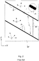
- Figure 2 this shows a prior-art situation corresponding to a conventional helical scan, in which the source Sx traces out a helical path relative to the axis L (by concurrently orbiting it about L, and displacing it parallel to L) and images are captured quasi-continuously ( i.e. at a high sampling rate) along a succession of closely-separated viewing axes V i .
- a result such as that shown in Figure 2 is obtained, in which trains of closely-spaced intersection points P i are located along (curvi-)linear tracts C (an exploded partial view at the top right of the Figure illustrates the close spacing of successive points Pi).
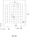
- Figures 3A-3D show distributions of intersection points P i resulting from embodiments of the present invention.
- the relative motion of the source Sx and specimen S, and the attendant sampling (image-capture) frequency/intervals are chosen so as to yield a two-dimensional lattice (matrix, net) M of points P i located areally on (at least part of) surface Sr' in a substantially uniform distribution.
- a unit cell M' Associated with this lattice M is a unit cell M', which can be regarded as a repeating fundamental "building block" of the lattice M . Note that:
- FIG. 4A is a highly schematic depiction of an embodiment of a CPM 1 that can be used in conjunction with the present invention; more specifically, it shows an embodiment of a SEM - though, in the context of the current invention, it could just as validly be an ion-based microscope, for example, or a TEM, for instance.
- the microscope 1 comprises a particle-optical column / illuminator 3, which produces a beam 5 of charged particles (in this case, an electron beam) that propagates along a particle-optical axis 5'.
- the particle-optical column 3 is mounted on a vacuum chamber 7, which comprises a specimen holder 9 and associated stage/actuator 11 for holding/positioning a specimen 13.
- the vacuum chamber 7 is evacuated using vacuum pumps (not depicted). With the aid of voltage source 15, the specimen holder 9, or at least the specimen 13, may, if desired, be biased (floated) to an electrical potential with respect to ground.
- the particle-optical column 3 comprises an electron source 17 (such as a Schottky emitter), (electrostatic/magnetic) lenses 19, 21 (in general, more complex in structure than the schematic depiction here) to focus the electron beam 5 onto the specimen 13, and a deflection unit 23 to perform beam deflection / scanning of the beam 5.
- an electron source 17 such as a Schottky emitter
- electrostatic/magnetic lenses 19, 21 in general, more complex in structure than the schematic depiction here
- the beam 5 impinges on / is scanned across the specimen 13, it will precipitate emission of various types of "stimulated” radiation, such as backscattered electrons, secondary electrons, X-rays and cathodoluminescence (infra-red, visible and/or ultra-violet photons); one or more of these radiation types can then be sensed/recorded using one or more detectors, which may form an image, spectrum, diffractogram, etc., typically by assembling a "map” (or “matrix”) of detector output as a function of scan position on the specimen.
- the present Figure shows two such detectors, 25, 27, which may, for example, be embodied as follows:
- the microscope 1 further comprises a controller / computer processing unit 31 for controlling inter alia the lenses 19 and 21, the deflection unit 23, and detectors 25, 27, and displaying information gathered from the detectors 25, 27 on a display unit 33 (such as a flat panel display); such control occurs via control lines (buses) 31'.
- the controller 31 (or another controller) can additionally be used to perform various mathematical processing, such as combining, integrating, subtracting, false colouring, edge enhancing, and other processing known to the skilled artisan.
- automated recognition processes e.g. as used for particle analysis may be included in such processing.
- a vacuum port 7' which may be opened so as to introduce/remove items (components, specimens) to/from the interior of vacuum chamber 7, or onto which, for example, an ancillary device/module may be mounted (not depicted).
- a microscope 1 may comprise a plurality of such ports 7', if desired.
- the microscope 1 can also comprise an in situ CT module 7" as shown in Figure 4B .
- the CPM's specimen holder 9 has been provided with a metal target 13', which is positioned (using actuator 11) so that electron beam 5 impinges upon it, thus producing Bremsstrahlung X-rays in a variety of directions.
- the Figure shows a beam B of such X-rays that propagate to one side from target 13' (effective source Sx) into module 7", where they pass through a specimen S and impinge upon a detector D: compare to Figure 1 .
- the specimen S is mounted on a stage apparatus A that allows the specimen S to be positioned/moved (typically translated and rotated) relative to the source Sx.
- Such a CT module 7" may be permanently present ( ab initio ) in the vacuum enclosure 7, or it may be an add-on module that can be mounted (post-manufacture of the CPM 1) on/within a spare vacuum port 7', for example.
Landscapes
- Health & Medical Sciences (AREA)
- General Physics & Mathematics (AREA)
- Physics & Mathematics (AREA)
- Engineering & Computer Science (AREA)
- Chemical & Material Sciences (AREA)
- Life Sciences & Earth Sciences (AREA)
- Analytical Chemistry (AREA)
- Theoretical Computer Science (AREA)
- General Health & Medical Sciences (AREA)
- Biochemistry (AREA)
- Immunology (AREA)
- Pathology (AREA)
- Nuclear Medicine, Radiotherapy & Molecular Imaging (AREA)
- Pulmonology (AREA)
- Radiology & Medical Imaging (AREA)
- Spectroscopy & Molecular Physics (AREA)
- Molecular Biology (AREA)
- High Energy & Nuclear Physics (AREA)
- Computer Vision & Pattern Recognition (AREA)
- Analysing Materials By The Use Of Radiation (AREA)
Description
- The invention relates to a method of investigating a specimen according to
claim 1 and a tomographic imaging apparatus according to claim 6. - The invention further relates to a charged-particle microscope provided with such a tomographic imaging apparatus.
- In tomographic imaging (also referred to as Computed Tomography (CT)) as referred to above, the source and (diametrically opposed) detector are used to look through the specimen along different lines of sight (viewing axes), so as to acquire penetrative observations of the specimen from a variety of perspectives; these are then used as input to a mathematical procedure that produces a reconstructed "volume image" of (part of) the (interior of) the specimen. In order to achieve a series of different lines of sight as alluded to here, one can, for example, choose to:
- (a) Keep the source and detector static and move the specimen relative to them;
- (b) Keep the specimen static and move the source relative to it. In this case, one can elect to:
- Move the detector in synchronization with the source; or
- Embody the detector as a (static) array of sub-detectors, with positions matched to correspond to the different positions to be assumed by the source.
- Tomographic imaging as referred to here can be performed using a standalone apparatus, which is conventionally the case in medical imaging applications, for example, where the specimen (e.g. a human or animal) is macroscopic. Standalone CT tools are also available for performing so-called "micro CT", in which a micro-focused source is used to image microscopic specimens, e.g. in geology/petrology, biological tissue studies, etc. Continuing this drive toward ever-greater resolution, so-called "nano CT" instruments have also been developed; these may be standalone tools, but, for example, they may also be embodied as (add-on) modules for (a vacant vacuum/interface port of) a charged-particle microscope (CPM), in which case the CPM's charged-particle beam is used to irradiate a metal target, causing production of the Bremsstrahlung X-rays used to perform the desired tomography (see
Figure 4B , for example). More information on (some) of these topics can, for example, be gleaned from the following references: - https://en.wikipedia.org/wiki/X-ray microtomography
- https://en.wikipedia.org/wiki/Nanotomography
- http://www.ndt.net/article/dir2007/papers/24.pdf
- Electrons, as in the case of a Transmission Electron Microscope (TEM), Scanning Electron Microscope (SEM), and Scanning Transmission Electron Microscope (STEM), for instance. See, for example, the following references:
- http://en.wikipedia.org/wiki/Electron microscope
- http://en.wikipedia.org/wiki/Scanninq electron microscope
- http://en.wikipedia.org/wiki/Transmission electron microscopy
- http://en.wikipedia.org/wiki/Scanning_transmission_electron_microscopy
- Ions, which may be positive (e.g. Ga or He ions) or negative. Such ion beams can be used for imaging purposes, but they are also often used for surface modification purposes, e.g. as in the case of Focused Ion Beam (FIB) milling, Ion-Beam-Induced Deposition (IBID), Ion-Beam-Induced Etching (IBIE), etc. See, for example, the following references:
- https://en.wikipedia.org/wiki/Focused ion beam
- http://en.wikipedia.org/wiki/Scanning Helium Ion Microscope
- Other charged particles, such as protons and positrons, for instance. See, for example, the following reference:
http://www.ncbi.nlm.nih.gov/pubmed/22472444 - As regards the specimen/source relative motion employed to achieve different lines of sight / viewing axes, use is conventionally made of:
- A circular scan, in which the source follows a planar orbit about the specimen, and images are captured at a very high sampling rate (i.e. quasi-continuously) along this orbit. This type of scan can be applied in situations where only a relatively thin "slice" of a specimen has to be imaged, e.g. when making a cone beam CT scan of human dentition. See, for example, the following reference:
https://en.wikipedia.org/wiki/Cone beam computed tomography - A helical scan, in which the source follows a coil-like (spiral) path about a (longitudinal) axis of the specimen, and images are again captured at a very high sampling rate (i.e. quasi-continuously) along this path. This type of scan can be applied in situations where a relatively elongated portion of a specimen has to be imaged, e.g. when making a CT scan of (a portion of) a human vertebral column. It is typically achieved by combining circular motion (e.g. of the source) and concurrent translational motion (e.g. of the specimen). See, for example, the following reference:
https://en.wikipedia.org/wiki/Spiral computed tomography - Although prior-art techniques such as these have produced tolerable results up to now, the current inventors have worked extensively to provide an innovative alternative to the conventional approach. The results of this endeavor are the subject of the current invention.
- It is an object of the invention to provide an innovative tomographic imaging technique. More specifically, it is an object of the invention that this technique should employ a radically different data acquisition strategy as compared to known techniques. Moreover, it is an object of the invention that this new acquisition strategy should admit use of novel data processing techniques.
- These and other objects are achieved in a method as set forth in the opening paragraph above, which method is characterized by the following steps:
- Selecting said set of sampling points to comprise a two-dimensional lattice of discrete points located areally on said reference surface in a substantially uniform distribution;
- Producing said tomographic image using at least one of:
- a Back Projection technique in combination with post-Back-Projection space-invariant filtering;
- a Multi-Grid Iterative Reconstruction technique in conjunction with space-invariant filtering.
- The current invention differs fundamentally from the prior art in the manner in which the specimen is sampled, i.e. in the manner in which a measurement set (comprising "raw" images captured along different sampling/viewing axes, and used as input to achieve the reconstructed tomographic output) is spatially acquired. Rather than employing an essentially continuous progression of sampling points that are concentrated/clustered along a scanning tract- such as a circle or helix - it instead employs a discrete lattice (network, array, web, matrix) of sampling points, which is areal (two-dimensional) rather than curvilinear (one-dimensional) in nature/geometry; accordingly, the sampling points (abovementioned intersection points) according to the invention are distributed substantially uniformly (homogeneously) across said virtual reference surface, as opposed to the prior art, in which their relatively cluttered arrangement on a curve is intrinsically non-uniform (inhomogeneous, and highly isotropic along the preferential direction defined by the course of the curve). It should be noted in this context that a "substantially uniform" distribution does not necessarily imply a "regular" distribution: the lattice distribution in the present invention may be regular (being a formal repeating array of a basic unit cell; see
Figures 3A ,3B or3D , for example), or irregular (as in the case of a (quasi-)random sprinkling of points; seeFigure 3C , for example), since both of these situations distribute sampling points in an areal manner instead of concentrating them along a sampling tract (seeFigure 2 , for example). For illustration purposes, somewhat of an analogy can be made here to the act of applying granulate fertilizer to a lawn, whereby: - In the prior-art analogy, the fertilizer is applied along one or more thin lines, leading to an overdose of fertilizer along the lines and fertilizer starvation between the lines;
- Using the inventive approach, the fertilizer is spread uniformly across the lawn; whether according to a strict matrix or a less formal scattering, the result is still a more uniform coverage of the lawn by the granules, with no (structural) overdosing or under-dosing.
- As a result of the fundamental differences set forth in the previous paragraph, the following important advantages can be achieved:
- (i) More uniform/isotropic sampling:
By nature, a sampling tract such as a circle or helix will have a high sampling density along one direction (the course followed by the tract), and much lower / zero sampling density along other directions (outside said course). Accordingly, a relatively large portion of the specimen will be proportionally under-sampled, whereas the remaining relatively small portion thereof (along the scanning tract) will be proportionally over-sampled. The present invention obviates this problem, by employing a sampling lattice that is substantially areally uniform. - (ii) Homogenized mean density of rays through the specimen / homogenized resolution:
If one considers a cone of rays moving from the source through the specimen and then onto the detector, a given point in the specimen will be impinged upon by a ray in a particular (angular) region of this cone. In a helical sampling strategy, successive source positions along the helix will cause said point to be impinged upon by rays in different (angular) regions of successive radiation cones; accordingly, the mean density of rays through the specimen will be anisotropic. In contrast, the uniform sampling strategy of the present invention mitigates this (undesirable) effect, and produces a substantially isotropic mean density of rays through the specimen. This homogenizes resolution in the reconstructed imagery. Put another way: it reduces/minimizes non-uniform magnification in the obtained tomogram. - (iii) Smaller input data set:
Because prior-art sampling strategies drastically over-sample (parts of) the imaged specimen along the sampling tract that they employ, they implicitly entail use of a wastefully large input data set, with an attendant excessively large calculation overhead (to construct an associated tomogram). This issue tends to become increasingly pronounced with increasing fan/cone angle. The more uniform sampling strategy of the present invention allows a much smaller data set to be used as input, with an associated (substantial) reduction in calculation overhead. - (iv) Homogenized Point Spread Function in reconstruction space:
The effect alluded to in (i) results in a more uniform/homogeneous/isotropic (shift-invariant) imaging Point Spread Function (PSF) in the mathematical "tomographic space" in which reconstruction occurs. This allows the reconstruction process to be performed using mathematical tools that cannot (practically) be employed in prior-art techniques. More specifically, it allows certain iterative reconstruction and pre-conditioning filtering techniques to be employed so as to accelerate convergence in the reconstruction process, thereby significantly reducing computational overhead/complexity. These techniques include post-back-projection Space-Invariant Filtering (SIF), and Multi-Grid Iterative Reconstruction (MGIR), which will be explained in greater detail below. - (v) Sparse sampling:
The uniform distribution of sampling points in the inventive approach lends itself to so-called sparse sampling strategies, e.g. by increasing the distance between neighboring/proximal points in the lattice. Such strategies cannot be (so easily) achieved in prior-art techniques. - In a particular embodiment of the present invention, the aforementioned lattice of sampling points has a geometry selected from the group comprising:
- An orthogonal array;
- A skewed orthogonal array;
- A staggered orthogonal array;
- A hexagonal array,
- (1) Orbit the source about the specimen (θ direction) and, during this orbit, take a discrete number of (relatively distal) samplings, at substantially equal arc spacings ΔO along the orbit;
- (2) For each completed orbit, shift the center of the orbit longitudinally (Z direction), by an amount ΔZ that is (roughly) equal to ΔO (both ΔO and ΔZ being measured at the same (orbital) radius from the specimen).
- If shift (2) occurs stepwise, after completion of each orbit (1), then one will obtain a lattice such as that illustrated in
Figures 3A or3B , for example. - On the other hand, if shift (2) occurs continually, during each orbit (1), then one will obtain a lattice such as that illustrated in
Figure 3D , for example. - If ΔZ is not exactly (but still roughly) equal to ΔO, then the unit cell M' in
Figure 3A will be (slightly) rectangular rather than square. Similarly, the parallelogram unit cells M' inFigures 3C and3D will become (slightly) longer along one side relative to a neighboring side. - One can use the previous point to distinguish the invention from the prior art in another way. If, in
Figure 2 , a pseudo-unit-cell M" is defined by joining 2x2 neighboring points in adjacent scanning tracts C, then the result will be a (highly) elongate parallelogram - indicative of the excessively high sampling density in one preferential (scanning tract) direction (short side of the parallelogram) and very low sampling density in the area between scanning tracts (long side of the parallelogram). - In the examples discussed above and illustrated in
Figure 1 , the following applies: - The specimen under investigation is elongate along a given longitudinal axis;
- The employed reference surface is cylindrical, and is arranged so that its cylindrical axis substantially coincides with said longitudinal axis.
- A common technique used in tomographic reconstruction is so-called Back Projection (BP). BP is a procedure whereby an image of a specimen, taken along a given viewing axis, is back-projected (smeared out) along that viewing axis, through the specimen. When this is done for several appropriately chosen viewing axes, the various back-projected images will intersect and form a blurry image at the location of the specimen, which blurry image then forms a basis for subsequent reconstructive processing. The present invention allows this procedure to be enhanced, by employing so-called Back Projection Filtering (BPF), in which a mathematical filtering process is applied to the various line-of-sight images after back projection. Inter alia because of inventive effects (i), (ii) and (iv) above, one has the luxury of being able to apply relatively straightforward space-invariant filters for this purpose; in contrast, the non-uniform / non-isotropic sampling scheme used in conventional helical scans precludes the use of a space-invariant filter, and prior-art approaches would instead have to use far more complicated - and essentially impracticable - space-variant filters if they were to attempt to achieve a similar filtering result. Unlike the prior art, the invention therefore allows back-projected imagery to be easily filtered, e.g. to accentuate certain (higher) frequencies and suppress other (lower) frequencies in Fourier space; this effect can be used to considerably sharpen the back-projected imagery before further reconstruction. Examples of space-invariant filters in the current context include, for instance, the Hilbert transform, Laplace operator, convolution operators, the Median filter, etc.
Care should be taken not to confuse BPF with the similarly-named - but very different - FBP (Filtered Back Projection) technique; in the former, filtering occurs after back projection (in reconstruction/tomographic space), whereas, in the latter, it occurs before back projection (in projection space). - As an alternative and/or supplement to the use of BP, one can instead make use of an iterative reconstruction technique to produce a tomographic image. Examples of such iterative techniques include SIRT (Simultaneous Iterative Reconstruction Technique), ART (Algebraic Reconstruction Technique), DART (Discrete ART), SART (Simultaneous ART), etc. Such iterative techniques (generally) have the advantage of being less noise-sensitive, and of allowing (physical) constraints to be applied to the reconstruction process; however, because they employ several iterations, they tend to be more time-consuming, and to converge relatively slowly. The current invention can mitigate this latter point by - once again - allowing space-invariant filtering to be applied, so as to sharpen-up the outcome of a given iteration before proceeding to the next iteration, thus speeding-up convergence. A particularly effective reconstruction technique in the present invention is MGIR (Multi-Grid Iterative Reconstruction), which starts with a relatively rough-grid construction and progresses iteratively through successively finer grids; when used in conjunction with space-invariant filtering as set forth above, this technique becomes very computationally efficient.
- The invention will now be elucidated in more detail on the basis of exemplary embodiments and the accompanying schematic drawings, in which:
-
Figure 1 renders a perspective view of a specimen undergoing tomographic imaging, and serves to explain certain (reference) geometric aspects of the current invention. -
Figure 2 renders an unfurled/flattened view of a (cylindrical) feature inFigure 1 , and serves to illustrate a prior-art sampling strategy. -
Figure 3A renders an unfurled/flattened view of a (cylindrical) feature inFigure 1 (in analogy toFigure 2 ), and serves to illustrate a particular embodiment of a sampling strategy according to the present invention. -
Figure 3B is similar toFigure 3A , but differs in that it illustrates a different embodiment of a sampling strategy according to the present invention. -
Figure 3C is similar toFigures 3A and3B , but differs in that it illustrates yet another embodiment of a sampling strategy according to the present invention. -
Figure 3D is similar toFigures 3A-3C , but differs in that it illustrates a further embodiment of a sampling strategy according to the present invention. -
Figure 4A renders a longitudinal cross-sectional elevation of a particular type of CPM in which an embodiment of the current invention can be carried out using a CT module. -
Figure 4B illustrates a CT module suitable for use in a CPM such as that shown inFigure 4A . -
Figure 1 renders a perspective view of a specimen S undergoing tomographic imaging, and serves to explain certain (reference) geometric aspects of the current invention. In the Figure, an elongated specimen S (which may be macroscopic, micron-scale, or nanometer-scale, for example) has an associated longitudinal axis L. A radiation source Sx produces a beam B of radiation (typically X-rays) that propagates along an axis Vi, which may be regarded as a viewing axis or line of sight. As here illustrated, Vi is substantially normal to longitudinal axis L. Having traversed a portion of the specimen S, the beam B impinges upon a (diametrically opposed) detector D, which may, for example, be a Silicon Drift Detector (SDD), Silicon Lithium (Si(Li)) detector, or other suitable detector. The beam B may be regarded as being (for example) cone- or fan-shaped, depending on the effective shape that the detector D "presents" to the source Sx. The detector D forms an electronic image of said portion of the specimen S, which can be stored in an electronic memory. This procedure is then repeated for a series of different viewing axes Vi, allowing the specimen S to be viewed along different lines of sight; thereafter, the various images acquired in this manner are used as input to a mathematical reconstruction procedure to produce a tomogram. The various viewing axes Vi are achieved by employing a stage apparatus (not depicted, but seeFigure 4B ) to produce relative motion between the source Sx and specimen S, e.g. by producing translational/rotational motion of the source Sx / detector D and/or the specimen S in a predetermined way. Such stage apparatus may, for example, comprise one or more linear motors, piezoelectric actuators, stepper motors, voice coil motors, pneumatic/hydraulic actuators, etc., and can readily be tailored by the skilled artisan to suit the needs of a given setup. - Also shown in the Figure is a virtual reference surface Sr, which, in this case, is a cylindrical surface whose cylindrical axis coincides with longitudinal axis L. This reference surface Sr has a radius Rsr, chosen to be less than or equal to the distance Rsx of the source Sx from the axis L. The viewing axis Vi intersects this reference surface Sr at intersection point Pi. Note that, if viewing axis Vi is projected linearly along L, it will coincide with a diameter of a virtual disc-shaped terminal surface St at butt ends of the surface Sr. Associated with the reference surface Sr is a cylindrical coordinate system (R, θ, Z). In
Figure 2 andFigures 3A-3D , the reference surface Sr has been unfurled (unwound about L) so as to form a flat surface Sr', with associated planar Cartesian coordinate system (Y, Z), whereby one can take Y = θR. - Turning first to
Figure 2 , this shows a prior-art situation corresponding to a conventional helical scan, in which the source Sx traces out a helical path relative to the axis L (by concurrently orbiting it about L, and displacing it parallel to L) and images are captured quasi-continuously (i.e. at a high sampling rate) along a succession of closely-separated viewing axes Vi. When the resulting helical path on reference surface Sr is unfurled, a result such as that shown inFigure 2 is obtained, in which trains of closely-spaced intersection points Pi are located along (curvi-)linear tracts C (an exploded partial view at the top right of the Figure illustrates the close spacing of successive points Pi). Note the extreme lack of homogeneity/isotropy in this situation: there is a high concentration of points along tracts C (which are highly directional), and no points at all in the intervening regions C'. - In stark contrast,
Figures 3A-3D show distributions of intersection points Pi resulting from embodiments of the present invention. Here, the relative motion of the source Sx and specimen S, and the attendant sampling (image-capture) frequency/intervals, are chosen so as to yield a two-dimensional lattice (matrix, net) M of points Pi located areally on (at least part of) surface Sr' in a substantially uniform distribution. Associated with this lattice M is a unit cell M', which can be regarded as a repeating fundamental "building block" of the lattice M . Note that: - (A) in
Figure 3A , the matrix M is substantially orthogonal, and the unit cell M' is a rectangle, which is essentially a square in the current situation. Such a pattern can, for example, be achieved by repeating the following steps:- Orbiting the source Sx about the line L in a horizontal orbital plane (normal to L), and taking equi-spaced samplings along this orbit at linear intervals ΔO. In
Figure 3A , there are ten points Pi along each horizontal row (Y row), meaning that ΔO = (2π/10) x Rsr. - After completion of each such circular orbit, displacing the orbital plane along the axis L by an amount ΔZ ≈ ΔO (with Rsr ≈ Rsx).
- Orbiting the source Sx about the line L in a horizontal orbital plane (normal to L), and taking equi-spaced samplings along this orbit at linear intervals ΔO. In
- (B) The situation in
Figure 3B is largely identical to that inFigure 3A , except in that the matrix M is now a staggered orthogonal matrix (or, alternatively, a trigonal or hexagonal matrix), with a unit cell M' that is a parallelogram (with substantially equal adjacent side lengths in the current situation). Such a pattern can be produced in the same way as that ofFigure 3A , except in that successive horizontal rows of points Pi are Y-shifted (by an amount ΔO/2 in the current situation). - (C) Whereas the lattice patterns M in
Figures 3A and3B are regular, the lattice pattern M inFigure 3C is irregular (quasi-random) - but nevertheless substantially uniform. There is no meaningful unit cell in this situation, but the distribution is still roughly homogeneous, on a relatively zoomed-out scale. Such a pattern can, for example, be produced using the technique in (A), except in that:- Sampling points in a given orbit are not necessarily equi-spaced along that orbit;
- Small Z positional adjustments can be made (up or down) in the course of an orbit.
Figure 3C can be seen as an on-the-fly-distorted rendition of the pattern inFigure 3A . - (D) The situation in
Figure 3D is largely identical to that inFigure 3A , except in that the matrix M is now a sheared orthogonal matrix, with a unit cell M' that is a canted parallelogram (once again with substantially equal adjacent side lengths in the current situation). Such a pattern can be produced in the same way as that ofFigure 3A , except in that the Z-shift is performed continuously during the orbital motion. This produces a helical motion, but the distance between successive sampling points along the helix is matched to the Z-spacing of successive windings in the helix, leading to a much more uniform distribution of points than in the prior-art case ofFigure 2B (effectively producing a form of "sparse helix"). For comparison purposes, a pseudo-unit-cell M" has been drawn inFigure 2 , which joins:- A first pair of adjacent sampling points along the direction of upper tract C;
- A second pair of adjacent sampling points along the direction of lower tract C, located directly below (and joined in the Z direction to) said first pair.
Figure 2 . -
Figure 4A is a highly schematic depiction of an embodiment of aCPM 1 that can be used in conjunction with the present invention; more specifically, it shows an embodiment of a SEM - though, in the context of the current invention, it could just as validly be an ion-based microscope, for example, or a TEM, for instance. Themicroscope 1 comprises a particle-optical column /illuminator 3, which produces abeam 5 of charged particles (in this case, an electron beam) that propagates along a particle-optical axis 5'. The particle-optical column 3 is mounted on avacuum chamber 7, which comprises aspecimen holder 9 and associated stage/actuator 11 for holding/positioning aspecimen 13. Thevacuum chamber 7 is evacuated using vacuum pumps (not depicted). With the aid ofvoltage source 15, thespecimen holder 9, or at least thespecimen 13, may, if desired, be biased (floated) to an electrical potential with respect to ground. - The particle-
optical column 3 comprises an electron source 17 (such as a Schottky emitter), (electrostatic/magnetic)lenses 19, 21 (in general, more complex in structure than the schematic depiction here) to focus theelectron beam 5 onto thespecimen 13, and adeflection unit 23 to perform beam deflection / scanning of thebeam 5. When thebeam 5 impinges on / is scanned across thespecimen 13, it will precipitate emission of various types of "stimulated" radiation, such as backscattered electrons, secondary electrons, X-rays and cathodoluminescence (infra-red, visible and/or ultra-violet photons); one or more of these radiation types can then be sensed/recorded using one or more detectors, which may form an image, spectrum, diffractogram, etc., typically by assembling a "map" (or "matrix") of detector output as a function of scan position on the specimen. The present Figure shows two such detectors, 25, 27, which may, for example, be embodied as follows: -
Detector 25 may, for example, be an electron detector (such as an Solid State PhotoMultiplier), X-ray detector (such as an SDD or Si(Li) sensor) or a light detector (such as a photodiode). -
Detector 27 is a segmented electron detector, comprising a plurality of independent detection segments (e.g. quadrants) disposed about a central aperture 29 (allowing passage of the beam 5). Such a detector can, for example, be used to investigate (the angular dependence of) a flux of output (secondary or backscattered) electrons emerging from thespecimen 13. - The
microscope 1 further comprises a controller /computer processing unit 31 for controlling inter alia thelenses deflection unit 23, anddetectors detectors - Also depicted is a vacuum port 7', which may be opened so as to introduce/remove items (components, specimens) to/from the interior of
vacuum chamber 7, or onto which, for example, an ancillary device/module may be mounted (not depicted). Amicroscope 1 may comprise a plurality of such ports 7', if desired. - In the context of the current invention, the
microscope 1 can also comprise an insitu CT module 7" as shown inFigure 4B . In this figure, the CPM'sspecimen holder 9 has been provided with a metal target 13', which is positioned (using actuator 11) so thatelectron beam 5 impinges upon it, thus producing Bremsstrahlung X-rays in a variety of directions. The Figure shows a beam B of such X-rays that propagate to one side from target 13' (effective source Sx) intomodule 7", where they pass through a specimen S and impinge upon a detector D: compare toFigure 1 . The specimen S is mounted on a stage apparatus A that allows the specimen S to be positioned/moved (typically translated and rotated) relative to the source Sx. - Such a
CT module 7" may be permanently present (ab initio) in thevacuum enclosure 7, or it may be an add-on module that can be mounted (post-manufacture of the CPM 1) on/within a spare vacuum port 7', for example.
The skilled artisan will understand that the employed reference surface does not necessarily have to be cylindrical, and that one could instead conceive, for example, a (substantially) spherical reference surface, with a (non-elongate) specimen at its center; such a reference surface might be convenient in the case of a specimen and/or detector that could be moved in spherical polar coordinates (R, θ, ϕ), for example.
Claims (7)
- A method of investigating a specimen using a tomographic imaging apparatus comprising:- A specimen holder, for holding the specimen;- A source, for producing a beam of radiation that can be directed at the specimen;- A detector, for detecting a flux of radiation transmitted through the specimen from the source;- A stage apparatus, for producing relative motion of the source with respect to the specimen, so as to allow the source and detector to image the specimen along a series of different viewing axes, which intersect a virtual reference surface that surrounds the specimen and is substantially centered thereon, thereby generating a corresponding set of sampling points;- A processing apparatus, for assembling output from the detector into a tomographic image of at least part of the specimen,the method being characterized by the following steps:- Selecting said set of sampling points to comprise a two-dimensional lattice of discrete points located areally on said reference surface in a substantially uniform distribution;- Producing said tomographic image using at least one of:• a Back Projection technique in combination with post-Back-Projection space-invariant filtering;• a Multi-Grid Iterative Reconstruction technique in conjunction with space-invariant filtering.
- A method according to claim 1, wherein the chosen series of viewing axes results in a substantially shift-invariant imaging Point Spread Function.
- A method according to claim 1 or 2, wherein at least part of said lattice of points has a geometry selected from the group comprising:- An orthogonal array;- A skewed orthogonal array;- A staggered orthogonal array;- A hexagonal array,and combinations hereof.
- A method according to claim 1 or 2, wherein at least part of said lattice of points has a non-regular geometry.
- A method according to any of claims 1-4, wherein:- Said specimen is elongate along a given longitudinal axis;- Said reference surface is cylindrical, and is arranged so that its cylindrical axis substantially coincides with said longitudinal axis.
- A tomographic imaging apparatus comprising:- A specimen holder, for holding a specimen;- A source, for producing a beam of radiation that can be directed at the specimen;- A detector, for detecting a flux of radiation transmitted through the specimen from the source;- A stage apparatus, for producing relative motion of the source with respect to the specimen, so as to allow the source and detector to image the specimen along a series of different viewing axes, which intersect a virtual reference surface that surrounds the specimen and is substantially centered thereon, thereby generating a corresponding set of sampling points;- A processing apparatus, for assembling output from the detector into a tomographic image of at least part of the specimen,characterized in that said processing apparatus is adapted to:- Select said set of sampling points to comprise a two-dimensional lattice of points located areally on said reference surface in a substantially uniform distribution;- Produce said tomographic image using at least one of:• a Back Projection technique in combination with post-Back-Projection space-invariant filtering;• a Multi-Grid Iterative Reconstruction technique in conjunction with space-invariant filtering.
- A charged-particle microscope comprising a tomographic imaging apparatus as claimed in claim 6.
Priority Applications (5)
| Application Number | Priority Date | Filing Date | Title |
|---|---|---|---|
| EP15181202.1A EP3133554B1 (en) | 2015-08-17 | 2015-08-17 | Novel acquisition and processing of data in a tomographic imaging apparatus |
| EP19170450.1A EP3534335A1 (en) | 2015-08-17 | 2015-08-17 | Novel acquisition and processing of data in a tomographic imaging apparatus |
| EP16180432.3A EP3133555B1 (en) | 2015-08-17 | 2016-07-20 | Novel data processing in a tomographic imaging apparatus |
| US15/237,309 US10254419B2 (en) | 2015-08-17 | 2016-08-15 | Acquisition and processing of data in a tomographic imaging apparatus |
| US16/284,496 US11428828B2 (en) | 2015-08-17 | 2019-02-25 | Acquisition and processing of data in a tomographic imaging apparatus |
Applications Claiming Priority (1)
| Application Number | Priority Date | Filing Date | Title |
|---|---|---|---|
| EP15181202.1A EP3133554B1 (en) | 2015-08-17 | 2015-08-17 | Novel acquisition and processing of data in a tomographic imaging apparatus |
Related Child Applications (2)
| Application Number | Title | Priority Date | Filing Date |
|---|---|---|---|
| EP19170450.1A Division-Into EP3534335A1 (en) | 2015-08-17 | 2015-08-17 | Novel acquisition and processing of data in a tomographic imaging apparatus |
| EP19170450.1A Division EP3534335A1 (en) | 2015-08-17 | 2015-08-17 | Novel acquisition and processing of data in a tomographic imaging apparatus |
Publications (2)
| Publication Number | Publication Date |
|---|---|
| EP3133554A1 EP3133554A1 (en) | 2017-02-22 |
| EP3133554B1 true EP3133554B1 (en) | 2019-07-10 |
Family
ID=53871954
Family Applications (2)
| Application Number | Title | Priority Date | Filing Date |
|---|---|---|---|
| EP19170450.1A Pending EP3534335A1 (en) | 2015-08-17 | 2015-08-17 | Novel acquisition and processing of data in a tomographic imaging apparatus |
| EP15181202.1A Revoked EP3133554B1 (en) | 2015-08-17 | 2015-08-17 | Novel acquisition and processing of data in a tomographic imaging apparatus |
Family Applications Before (1)
| Application Number | Title | Priority Date | Filing Date |
|---|---|---|---|
| EP19170450.1A Pending EP3534335A1 (en) | 2015-08-17 | 2015-08-17 | Novel acquisition and processing of data in a tomographic imaging apparatus |
Country Status (2)
| Country | Link |
|---|---|
| US (2) | US10254419B2 (en) |
| EP (2) | EP3534335A1 (en) |
Cited By (1)
| Publication number | Priority date | Publication date | Assignee | Title |
|---|---|---|---|---|
| EP3977937A1 (en) | 2020-09-30 | 2022-04-06 | FEI Company | Method of investigating a specimen using a tomographic imaging apparatus |
Families Citing this family (5)
| Publication number | Priority date | Publication date | Assignee | Title |
|---|---|---|---|---|
| US10514343B2 (en) * | 2015-02-27 | 2019-12-24 | Carl Zeiss X-ray Microscopy, Inc. | X-ray CT microscopy system and method utilizing lattice sampling |
| EP3136345A1 (en) | 2015-08-24 | 2017-03-01 | FEI Company | Positional error correction in a tomographic imaging apparatus |
| EP3065160B1 (en) | 2015-11-02 | 2017-12-20 | FEI Company | Post column filter with enhanced energy range |
| US10685759B2 (en) | 2017-01-16 | 2020-06-16 | Fei Company | Statistical analysis in X-ray imaging |
| CN111398120B (en) * | 2020-03-31 | 2020-12-15 | 中国科学院地质与地球物理研究所 | Method for representing porous medium pore by combining helium ion microscope and scanning electron microscope |
Family Cites Families (21)
| Publication number | Priority date | Publication date | Assignee | Title |
|---|---|---|---|---|
| US4196352A (en) * | 1978-04-28 | 1980-04-01 | General Electric Company | Multiple purpose high speed tomographic x-ray scanner |
| US5090245A (en) * | 1986-05-02 | 1992-02-25 | Anderson Forrest L | Three dimensional imaging device using filtered ellipsoidal backprojection |
| US5611026A (en) * | 1992-12-21 | 1997-03-11 | General Electric Company | Combining a priori data with partial scan data to project three dimensional imaging of arbitrary objects with computerized tomography |
| US6061420A (en) * | 1998-08-25 | 2000-05-09 | General Electric Company | Methods and apparatus for graphical Rx in a multislice imaging system |
| US6504898B1 (en) * | 2000-04-17 | 2003-01-07 | Mds (Canada) Inc. | Product irradiator for optimizing dose uniformity in products |
| DE10021219A1 (en) * | 2000-04-29 | 2001-10-31 | Philips Corp Intellectual Pty | Computer tomography procedure |
| US6778630B2 (en) * | 2001-03-23 | 2004-08-17 | Kabushiki Kaisha Toshiba | Method and system for reconstructing computed tomography images using redundant data |
| US6459756B1 (en) * | 2001-10-30 | 2002-10-01 | Siemens Corporate Research, Inc. | System and method for providing normalization correction for image reconstruction in a reduced pitch spiral scan cone beam computed tomography imaging system |
| US7403587B2 (en) * | 2003-09-05 | 2008-07-22 | Koninklijke Philips Electronics N.V. | Computer tomography method using a cone-shaped bundle of rays |
| JP4299208B2 (en) * | 2004-08-20 | 2009-07-22 | 日本電子株式会社 | 3D image construction method |
| US9046465B2 (en) * | 2011-02-24 | 2015-06-02 | Rapiscan Systems, Inc. | Optimization of the source firing pattern for X-ray scanning systems |
| US7269244B2 (en) * | 2006-01-25 | 2007-09-11 | General Electric Company | Methods and apparatus for generating thick images in cone beam volumetric CT |
| US7428292B2 (en) * | 2006-11-24 | 2008-09-23 | General Electric Company | Method and system for CT imaging using multi-spot emission sources |
| US8139709B2 (en) * | 2008-09-15 | 2012-03-20 | University Of Utah Research Foundation | Staggered circular scans for CT imaging |
| EP2764380B1 (en) * | 2011-10-03 | 2022-02-23 | Fei Company | A computed tomography imaging process and system |
| US9069092B2 (en) * | 2012-02-22 | 2015-06-30 | L-3 Communication Security and Detection Systems Corp. | X-ray imager with sparse detector array |
| EP2738786A1 (en) * | 2012-11-29 | 2014-06-04 | Fei Company | Method of performing tomographic imaging of a sample in a charged-particle microscope |
| US10004464B2 (en) * | 2013-01-31 | 2018-06-26 | Duke University | System for improved compressive tomography and method therefor |
| US10514343B2 (en) * | 2015-02-27 | 2019-12-24 | Carl Zeiss X-ray Microscopy, Inc. | X-ray CT microscopy system and method utilizing lattice sampling |
| EP3082150B1 (en) * | 2015-04-15 | 2017-07-19 | FEI Company | Method and scanning transmission type charged-particle microscope for performing tomographic imaging |
| US10685759B2 (en) * | 2017-01-16 | 2020-06-16 | Fei Company | Statistical analysis in X-ray imaging |
-
2015
- 2015-08-17 EP EP19170450.1A patent/EP3534335A1/en active Pending
- 2015-08-17 EP EP15181202.1A patent/EP3133554B1/en not_active Revoked
-
2016
- 2016-08-15 US US15/237,309 patent/US10254419B2/en active Active
-
2019
- 2019-02-25 US US16/284,496 patent/US11428828B2/en active Active
Non-Patent Citations (1)
| Title |
|---|
| None * |
Cited By (1)
| Publication number | Priority date | Publication date | Assignee | Title |
|---|---|---|---|---|
| EP3977937A1 (en) | 2020-09-30 | 2022-04-06 | FEI Company | Method of investigating a specimen using a tomographic imaging apparatus |
Also Published As
| Publication number | Publication date |
|---|---|
| EP3133554A1 (en) | 2017-02-22 |
| US20170052264A1 (en) | 2017-02-23 |
| US20190187306A1 (en) | 2019-06-20 |
| US11428828B2 (en) | 2022-08-30 |
| US10254419B2 (en) | 2019-04-09 |
| EP3534335A1 (en) | 2019-09-04 |
Similar Documents
| Publication | Publication Date | Title |
|---|---|---|
| US11428828B2 (en) | Acquisition and processing of data in a tomographic imaging apparatus | |
| EP3171163B1 (en) | X-ray imaging technique | |
| EP2738787B1 (en) | Method of performing tomographic imaging of a sample in a charged-particle microscope | |
| US10224174B1 (en) | Transmission charged particle microscope with imaging beam rotation | |
| JP7273541B2 (en) | Investigation methods for dynamic samples in transmission charged particle microscopy and transmission charged particle microscopy | |
| US10078057B2 (en) | Data processing in a tomographic imaging apparatus | |
| EP2966668B1 (en) | Method of calibrating a scanning transmission charged-particle microscope | |
| US10152785B2 (en) | Positional error correction in a tomographic imaging apparatus | |
| JP7007136B2 (en) | Tomographic imaging method | |
| CN107917923B (en) | Arrangement for X-ray tomography | |
| EP3133555B1 (en) | Novel data processing in a tomographic imaging apparatus | |
| EP3977937A1 (en) | Method of investigating a specimen using a tomographic imaging apparatus | |
| JP2022509915A (en) | Electron diffraction imaging system for determining molecular structure and conformation | |
| WO2022202586A1 (en) | 3d image observation device and method | |
| Nicholls | Compressive Sensing Methods and Applications for Electron Microscopy |
Legal Events
| Date | Code | Title | Description |
|---|---|---|---|
| PUAI | Public reference made under article 153(3) epc to a published international application that has entered the european phase |
Free format text: ORIGINAL CODE: 0009012 |
|
| STAA | Information on the status of an ep patent application or granted ep patent |
Free format text: STATUS: THE APPLICATION HAS BEEN PUBLISHED |
|
| AK | Designated contracting states |
Kind code of ref document: A1 Designated state(s): AL AT BE BG CH CY CZ DE DK EE ES FI FR GB GR HR HU IE IS IT LI LT LU LV MC MK MT NL NO PL PT RO RS SE SI SK SM TR |
|
| AX | Request for extension of the european patent |
Extension state: BA ME |
|
| STAA | Information on the status of an ep patent application or granted ep patent |
Free format text: STATUS: REQUEST FOR EXAMINATION WAS MADE |
|
| 17P | Request for examination filed |
Effective date: 20170818 |
|
| RBV | Designated contracting states (corrected) |
Designated state(s): AL AT BE BG CH CY CZ DE DK EE ES FI FR GB GR HR HU IE IS IT LI LT LU LV MC MK MT NL NO PL PT RO RS SE SI SK SM TR |
|
| RIC1 | Information provided on ipc code assigned before grant |
Ipc: G01N 23/046 20180101ALI20190228BHEP Ipc: G06T 11/00 20060101AFI20190228BHEP |
|
| GRAP | Despatch of communication of intention to grant a patent |
Free format text: ORIGINAL CODE: EPIDOSNIGR1 |
|
| STAA | Information on the status of an ep patent application or granted ep patent |
Free format text: STATUS: GRANT OF PATENT IS INTENDED |
|
| INTG | Intention to grant announced |
Effective date: 20190408 |
|
| GRAS | Grant fee paid |
Free format text: ORIGINAL CODE: EPIDOSNIGR3 |
|
| GRAA | (expected) grant |
Free format text: ORIGINAL CODE: 0009210 |
|
| STAA | Information on the status of an ep patent application or granted ep patent |
Free format text: STATUS: THE PATENT HAS BEEN GRANTED |
|
| AK | Designated contracting states |
Kind code of ref document: B1 Designated state(s): AL AT BE BG CH CY CZ DE DK EE ES FI FR GB GR HR HU IE IS IT LI LT LU LV MC MK MT NL NO PL PT RO RS SE SI SK SM TR |
|
| REG | Reference to a national code |
Ref country code: GB Ref legal event code: FG4D |
|
| REG | Reference to a national code |
Ref country code: CH Ref legal event code: EP Ref country code: AT Ref legal event code: REF Ref document number: 1154363 Country of ref document: AT Kind code of ref document: T Effective date: 20190715 |
|
| REG | Reference to a national code |
Ref country code: DE Ref legal event code: R096 Ref document number: 602015033420 Country of ref document: DE |
|
| REG | Reference to a national code |
Ref country code: IE Ref legal event code: FG4D |
|
| REG | Reference to a national code |
Ref country code: NL Ref legal event code: MP Effective date: 20190710 |
|
| REG | Reference to a national code |
Ref country code: LT Ref legal event code: MG4D |
|
| REG | Reference to a national code |
Ref country code: AT Ref legal event code: MK05 Ref document number: 1154363 Country of ref document: AT Kind code of ref document: T Effective date: 20190710 |
|
| PG25 | Lapsed in a contracting state [announced via postgrant information from national office to epo] |
Ref country code: LT Free format text: LAPSE BECAUSE OF FAILURE TO SUBMIT A TRANSLATION OF THE DESCRIPTION OR TO PAY THE FEE WITHIN THE PRESCRIBED TIME-LIMIT Effective date: 20190710 Ref country code: HR Free format text: LAPSE BECAUSE OF FAILURE TO SUBMIT A TRANSLATION OF THE DESCRIPTION OR TO PAY THE FEE WITHIN THE PRESCRIBED TIME-LIMIT Effective date: 20190710 Ref country code: PT Free format text: LAPSE BECAUSE OF FAILURE TO SUBMIT A TRANSLATION OF THE DESCRIPTION OR TO PAY THE FEE WITHIN THE PRESCRIBED TIME-LIMIT Effective date: 20191111 Ref country code: BG Free format text: LAPSE BECAUSE OF FAILURE TO SUBMIT A TRANSLATION OF THE DESCRIPTION OR TO PAY THE FEE WITHIN THE PRESCRIBED TIME-LIMIT Effective date: 20191010 Ref country code: NO Free format text: LAPSE BECAUSE OF FAILURE TO SUBMIT A TRANSLATION OF THE DESCRIPTION OR TO PAY THE FEE WITHIN THE PRESCRIBED TIME-LIMIT Effective date: 20191010 Ref country code: NL Free format text: LAPSE BECAUSE OF FAILURE TO SUBMIT A TRANSLATION OF THE DESCRIPTION OR TO PAY THE FEE WITHIN THE PRESCRIBED TIME-LIMIT Effective date: 20190710 Ref country code: AT Free format text: LAPSE BECAUSE OF FAILURE TO SUBMIT A TRANSLATION OF THE DESCRIPTION OR TO PAY THE FEE WITHIN THE PRESCRIBED TIME-LIMIT Effective date: 20190710 Ref country code: FI Free format text: LAPSE BECAUSE OF FAILURE TO SUBMIT A TRANSLATION OF THE DESCRIPTION OR TO PAY THE FEE WITHIN THE PRESCRIBED TIME-LIMIT Effective date: 20190710 Ref country code: SE Free format text: LAPSE BECAUSE OF FAILURE TO SUBMIT A TRANSLATION OF THE DESCRIPTION OR TO PAY THE FEE WITHIN THE PRESCRIBED TIME-LIMIT Effective date: 20190710 |
|
| PG25 | Lapsed in a contracting state [announced via postgrant information from national office to epo] |
Ref country code: RS Free format text: LAPSE BECAUSE OF FAILURE TO SUBMIT A TRANSLATION OF THE DESCRIPTION OR TO PAY THE FEE WITHIN THE PRESCRIBED TIME-LIMIT Effective date: 20190710 Ref country code: LV Free format text: LAPSE BECAUSE OF FAILURE TO SUBMIT A TRANSLATION OF THE DESCRIPTION OR TO PAY THE FEE WITHIN THE PRESCRIBED TIME-LIMIT Effective date: 20190710 Ref country code: GR Free format text: LAPSE BECAUSE OF FAILURE TO SUBMIT A TRANSLATION OF THE DESCRIPTION OR TO PAY THE FEE WITHIN THE PRESCRIBED TIME-LIMIT Effective date: 20191011 Ref country code: IS Free format text: LAPSE BECAUSE OF FAILURE TO SUBMIT A TRANSLATION OF THE DESCRIPTION OR TO PAY THE FEE WITHIN THE PRESCRIBED TIME-LIMIT Effective date: 20191110 Ref country code: AL Free format text: LAPSE BECAUSE OF FAILURE TO SUBMIT A TRANSLATION OF THE DESCRIPTION OR TO PAY THE FEE WITHIN THE PRESCRIBED TIME-LIMIT Effective date: 20190710 Ref country code: ES Free format text: LAPSE BECAUSE OF FAILURE TO SUBMIT A TRANSLATION OF THE DESCRIPTION OR TO PAY THE FEE WITHIN THE PRESCRIBED TIME-LIMIT Effective date: 20190710 |
|
| PG25 | Lapsed in a contracting state [announced via postgrant information from national office to epo] |
Ref country code: TR Free format text: LAPSE BECAUSE OF FAILURE TO SUBMIT A TRANSLATION OF THE DESCRIPTION OR TO PAY THE FEE WITHIN THE PRESCRIBED TIME-LIMIT Effective date: 20190710 |
|
| REG | Reference to a national code |
Ref country code: DE Ref legal event code: R026 Ref document number: 602015033420 Country of ref document: DE |
|
| PLBI | Opposition filed |
Free format text: ORIGINAL CODE: 0009260 |
|
| PG25 | Lapsed in a contracting state [announced via postgrant information from national office to epo] |
Ref country code: DK Free format text: LAPSE BECAUSE OF FAILURE TO SUBMIT A TRANSLATION OF THE DESCRIPTION OR TO PAY THE FEE WITHIN THE PRESCRIBED TIME-LIMIT Effective date: 20190710 Ref country code: PL Free format text: LAPSE BECAUSE OF FAILURE TO SUBMIT A TRANSLATION OF THE DESCRIPTION OR TO PAY THE FEE WITHIN THE PRESCRIBED TIME-LIMIT Effective date: 20190710 Ref country code: EE Free format text: LAPSE BECAUSE OF FAILURE TO SUBMIT A TRANSLATION OF THE DESCRIPTION OR TO PAY THE FEE WITHIN THE PRESCRIBED TIME-LIMIT Effective date: 20190710 Ref country code: IT Free format text: LAPSE BECAUSE OF FAILURE TO SUBMIT A TRANSLATION OF THE DESCRIPTION OR TO PAY THE FEE WITHIN THE PRESCRIBED TIME-LIMIT Effective date: 20190710 Ref country code: RO Free format text: LAPSE BECAUSE OF FAILURE TO SUBMIT A TRANSLATION OF THE DESCRIPTION OR TO PAY THE FEE WITHIN THE PRESCRIBED TIME-LIMIT Effective date: 20190710 |
|
| 26 | Opposition filed |
Opponent name: CARL ZEISS X-RAY MICROSCOPY, INC. Effective date: 20200408 |
|
| PG25 | Lapsed in a contracting state [announced via postgrant information from national office to epo] |
Ref country code: IS Free format text: LAPSE BECAUSE OF FAILURE TO SUBMIT A TRANSLATION OF THE DESCRIPTION OR TO PAY THE FEE WITHIN THE PRESCRIBED TIME-LIMIT Effective date: 20200224 Ref country code: CH Free format text: LAPSE BECAUSE OF NON-PAYMENT OF DUE FEES Effective date: 20190831 Ref country code: LI Free format text: LAPSE BECAUSE OF NON-PAYMENT OF DUE FEES Effective date: 20190831 Ref country code: SK Free format text: LAPSE BECAUSE OF FAILURE TO SUBMIT A TRANSLATION OF THE DESCRIPTION OR TO PAY THE FEE WITHIN THE PRESCRIBED TIME-LIMIT Effective date: 20190710 Ref country code: MC Free format text: LAPSE BECAUSE OF FAILURE TO SUBMIT A TRANSLATION OF THE DESCRIPTION OR TO PAY THE FEE WITHIN THE PRESCRIBED TIME-LIMIT Effective date: 20190710 Ref country code: SM Free format text: LAPSE BECAUSE OF FAILURE TO SUBMIT A TRANSLATION OF THE DESCRIPTION OR TO PAY THE FEE WITHIN THE PRESCRIBED TIME-LIMIT Effective date: 20190710 Ref country code: LU Free format text: LAPSE BECAUSE OF NON-PAYMENT OF DUE FEES Effective date: 20190817 |
|
| REG | Reference to a national code |
Ref country code: BE Ref legal event code: MM Effective date: 20190831 |
|
| PLAX | Notice of opposition and request to file observation + time limit sent |
Free format text: ORIGINAL CODE: EPIDOSNOBS2 |
|
| PG2D | Information on lapse in contracting state deleted |
Ref country code: IS |
|
| PG25 | Lapsed in a contracting state [announced via postgrant information from national office to epo] |
Ref country code: IE Free format text: LAPSE BECAUSE OF NON-PAYMENT OF DUE FEES Effective date: 20190817 |
|
| PG25 | Lapsed in a contracting state [announced via postgrant information from national office to epo] |
Ref country code: SI Free format text: LAPSE BECAUSE OF FAILURE TO SUBMIT A TRANSLATION OF THE DESCRIPTION OR TO PAY THE FEE WITHIN THE PRESCRIBED TIME-LIMIT Effective date: 20190710 Ref country code: BE Free format text: LAPSE BECAUSE OF NON-PAYMENT OF DUE FEES Effective date: 20190831 |
|
| PLBB | Reply of patent proprietor to notice(s) of opposition received |
Free format text: ORIGINAL CODE: EPIDOSNOBS3 |
|
| PG25 | Lapsed in a contracting state [announced via postgrant information from national office to epo] |
Ref country code: CY Free format text: LAPSE BECAUSE OF FAILURE TO SUBMIT A TRANSLATION OF THE DESCRIPTION OR TO PAY THE FEE WITHIN THE PRESCRIBED TIME-LIMIT Effective date: 20190710 |
|
| PG25 | Lapsed in a contracting state [announced via postgrant information from national office to epo] |
Ref country code: HU Free format text: LAPSE BECAUSE OF FAILURE TO SUBMIT A TRANSLATION OF THE DESCRIPTION OR TO PAY THE FEE WITHIN THE PRESCRIBED TIME-LIMIT; INVALID AB INITIO Effective date: 20150817 Ref country code: MT Free format text: LAPSE BECAUSE OF FAILURE TO SUBMIT A TRANSLATION OF THE DESCRIPTION OR TO PAY THE FEE WITHIN THE PRESCRIBED TIME-LIMIT Effective date: 20190710 |
|
| PGFP | Annual fee paid to national office [announced via postgrant information from national office to epo] |
Ref country code: CZ Payment date: 20210727 Year of fee payment: 7 Ref country code: FR Payment date: 20210714 Year of fee payment: 7 |
|
| PGFP | Annual fee paid to national office [announced via postgrant information from national office to epo] |
Ref country code: GB Payment date: 20210707 Year of fee payment: 7 Ref country code: DE Payment date: 20210706 Year of fee payment: 7 |
|
| REG | Reference to a national code |
Ref country code: DE Ref legal event code: R103 Ref document number: 602015033420 Country of ref document: DE Ref country code: DE Ref legal event code: R064 Ref document number: 602015033420 Country of ref document: DE |
|
| RDAF | Communication despatched that patent is revoked |
Free format text: ORIGINAL CODE: EPIDOSNREV1 |
|
| PG25 | Lapsed in a contracting state [announced via postgrant information from national office to epo] |
Ref country code: MK Free format text: LAPSE BECAUSE OF FAILURE TO SUBMIT A TRANSLATION OF THE DESCRIPTION OR TO PAY THE FEE WITHIN THE PRESCRIBED TIME-LIMIT Effective date: 20190710 |
|
| RDAG | Patent revoked |
Free format text: ORIGINAL CODE: 0009271 |
|
| STAA | Information on the status of an ep patent application or granted ep patent |
Free format text: STATUS: PATENT REVOKED |
|
| REG | Reference to a national code |
Ref country code: CH Ref legal event code: PL |
|
| REG | Reference to a national code |
Ref country code: FI Ref legal event code: MGE |
|
| 27W | Patent revoked |
Effective date: 20211207 |
|
| GBPR | Gb: patent revoked under art. 102 of the ep convention designating the uk as contracting state |
Effective date: 20211207 |