EP3133426B1 - Optical fiber article for handling h igher power and method of fabricating or using it - Google Patents
Optical fiber article for handling h igher power and method of fabricating or using it Download PDFInfo
- Publication number
- EP3133426B1 EP3133426B1 EP16164387.9A EP16164387A EP3133426B1 EP 3133426 B1 EP3133426 B1 EP 3133426B1 EP 16164387 A EP16164387 A EP 16164387A EP 3133426 B1 EP3133426 B1 EP 3133426B1
- Authority
- EP
- European Patent Office
- Prior art keywords
- core
- preform
- optical fiber
- fiber
- region
- Prior art date
- Legal status (The legal status is an assumption and is not a legal conclusion. Google has not performed a legal analysis and makes no representation as to the accuracy of the status listed.)
- Active
Links
Images


Classifications
-
- C—CHEMISTRY; METALLURGY
- C03—GLASS; MINERAL OR SLAG WOOL
- C03B—MANUFACTURE, SHAPING, OR SUPPLEMENTARY PROCESSES
- C03B37/00—Manufacture or treatment of flakes, fibres, or filaments from softened glass, minerals, or slags
- C03B37/01—Manufacture of glass fibres or filaments
- C03B37/012—Manufacture of preforms for drawing fibres or filaments
- C03B37/01205—Manufacture of preforms for drawing fibres or filaments starting from tubes, rods, fibres or filaments
- C03B37/01211—Manufacture of preforms for drawing fibres or filaments starting from tubes, rods, fibres or filaments by inserting one or more rods or tubes into a tube
- C03B37/01222—Manufacture of preforms for drawing fibres or filaments starting from tubes, rods, fibres or filaments by inserting one or more rods or tubes into a tube for making preforms of multiple core optical fibres
-
- C—CHEMISTRY; METALLURGY
- C03—GLASS; MINERAL OR SLAG WOOL
- C03B—MANUFACTURE, SHAPING, OR SUPPLEMENTARY PROCESSES
- C03B37/00—Manufacture or treatment of flakes, fibres, or filaments from softened glass, minerals, or slags
- C03B37/01—Manufacture of glass fibres or filaments
- C03B37/012—Manufacture of preforms for drawing fibres or filaments
- C03B37/01205—Manufacture of preforms for drawing fibres or filaments starting from tubes, rods, fibres or filaments
- C03B37/01225—Means for changing or stabilising the shape, e.g. diameter, of tubes or rods in general, e.g. collapsing
- C03B37/01228—Removal of preform material
-
- C—CHEMISTRY; METALLURGY
- C03—GLASS; MINERAL OR SLAG WOOL
- C03B—MANUFACTURE, SHAPING, OR SUPPLEMENTARY PROCESSES
- C03B37/00—Manufacture or treatment of flakes, fibres, or filaments from softened glass, minerals, or slags
- C03B37/01—Manufacture of glass fibres or filaments
- C03B37/012—Manufacture of preforms for drawing fibres or filaments
- C03B37/01205—Manufacture of preforms for drawing fibres or filaments starting from tubes, rods, fibres or filaments
- C03B37/01225—Means for changing or stabilising the shape, e.g. diameter, of tubes or rods in general, e.g. collapsing
- C03B37/01228—Removal of preform material
- C03B37/01231—Removal of preform material to form a longitudinal hole, e.g. by drilling
-
- C—CHEMISTRY; METALLURGY
- C03—GLASS; MINERAL OR SLAG WOOL
- C03B—MANUFACTURE, SHAPING, OR SUPPLEMENTARY PROCESSES
- C03B37/00—Manufacture or treatment of flakes, fibres, or filaments from softened glass, minerals, or slags
- C03B37/01—Manufacture of glass fibres or filaments
- C03B37/02—Manufacture of glass fibres or filaments by drawing or extruding, e.g. direct drawing of molten glass from nozzles; Cooling fins therefor
- C03B37/025—Manufacture of glass fibres or filaments by drawing or extruding, e.g. direct drawing of molten glass from nozzles; Cooling fins therefor from reheated softened tubes, rods, fibres or filaments, e.g. drawing fibres from preforms
- C03B37/027—Fibres composed of different sorts of glass, e.g. glass optical fibres
- C03B37/02763—Fibres having axial variations, e.g. axially varying diameter, material or optical properties
-
- G—PHYSICS
- G02—OPTICS
- G02B—OPTICAL ELEMENTS, SYSTEMS OR APPARATUS
- G02B6/00—Light guides; Structural details of arrangements comprising light guides and other optical elements, e.g. couplings
- G02B6/02—Optical fibres with cladding with or without a coating
- G02B6/02042—Multicore optical fibres
-
- H—ELECTRICITY
- H01—ELECTRIC ELEMENTS
- H01S—DEVICES USING THE PROCESS OF LIGHT AMPLIFICATION BY STIMULATED EMISSION OF RADIATION [LASER] TO AMPLIFY OR GENERATE LIGHT; DEVICES USING STIMULATED EMISSION OF ELECTROMAGNETIC RADIATION IN WAVE RANGES OTHER THAN OPTICAL
- H01S3/00—Lasers, i.e. devices using stimulated emission of electromagnetic radiation in the infrared, visible or ultraviolet wave range
- H01S3/05—Construction or shape of optical resonators; Accommodation of active medium therein; Shape of active medium
- H01S3/06—Construction or shape of active medium
- H01S3/063—Waveguide lasers, i.e. whereby the dimensions of the waveguide are of the order of the light wavelength
- H01S3/067—Fibre lasers
- H01S3/06704—Housings; Packages
-
- C—CHEMISTRY; METALLURGY
- C03—GLASS; MINERAL OR SLAG WOOL
- C03B—MANUFACTURE, SHAPING, OR SUPPLEMENTARY PROCESSES
- C03B2203/00—Fibre product details, e.g. structure, shape
- C03B2203/10—Internal structure or shape details
- C03B2203/18—Axial perturbations, e.g. in refractive index or composition
-
- C—CHEMISTRY; METALLURGY
- C03—GLASS; MINERAL OR SLAG WOOL
- C03B—MANUFACTURE, SHAPING, OR SUPPLEMENTARY PROCESSES
- C03B2203/00—Fibre product details, e.g. structure, shape
- C03B2203/10—Internal structure or shape details
- C03B2203/18—Axial perturbations, e.g. in refractive index or composition
- C03B2203/20—Axial perturbations, e.g. in refractive index or composition helical
-
- C—CHEMISTRY; METALLURGY
- C03—GLASS; MINERAL OR SLAG WOOL
- C03B—MANUFACTURE, SHAPING, OR SUPPLEMENTARY PROCESSES
- C03B2203/00—Fibre product details, e.g. structure, shape
- C03B2203/32—Eccentric core or cladding
-
- C—CHEMISTRY; METALLURGY
- C03—GLASS; MINERAL OR SLAG WOOL
- C03B—MANUFACTURE, SHAPING, OR SUPPLEMENTARY PROCESSES
- C03B2203/00—Fibre product details, e.g. structure, shape
- C03B2203/34—Plural core other than bundles, e.g. double core
-
- C—CHEMISTRY; METALLURGY
- C03—GLASS; MINERAL OR SLAG WOOL
- C03B—MANUFACTURE, SHAPING, OR SUPPLEMENTARY PROCESSES
- C03B2205/00—Fibre drawing or extruding details
- C03B2205/06—Rotating the fibre fibre about its longitudinal axis
-
- C—CHEMISTRY; METALLURGY
- C03—GLASS; MINERAL OR SLAG WOOL
- C03B—MANUFACTURE, SHAPING, OR SUPPLEMENTARY PROCESSES
- C03B2205/00—Fibre drawing or extruding details
- C03B2205/06—Rotating the fibre fibre about its longitudinal axis
- C03B2205/07—Rotating the preform about its longitudinal axis
-
- H—ELECTRICITY
- H01—ELECTRIC ELEMENTS
- H01S—DEVICES USING THE PROCESS OF LIGHT AMPLIFICATION BY STIMULATED EMISSION OF RADIATION [LASER] TO AMPLIFY OR GENERATE LIGHT; DEVICES USING STIMULATED EMISSION OF ELECTROMAGNETIC RADIATION IN WAVE RANGES OTHER THAN OPTICAL
- H01S3/00—Lasers, i.e. devices using stimulated emission of electromagnetic radiation in the infrared, visible or ultraviolet wave range
- H01S3/05—Construction or shape of optical resonators; Accommodation of active medium therein; Shape of active medium
- H01S3/06—Construction or shape of active medium
- H01S3/063—Waveguide lasers, i.e. whereby the dimensions of the waveguide are of the order of the light wavelength
- H01S3/067—Fibre lasers
- H01S3/06708—Constructional details of the fibre, e.g. compositions, cross-section, shape or tapering
Definitions
- the present invention relates to fiber optic articles, such as optical fibers, optical fiber preforms and the like, and methods for making fiber optic articles.
- Fiber lasers and fiber amplifiers capable of handling higher powers are of considerable interest.
- non-linear effects such as Simulated Brillioun Scattering (SBS) and Stimulated Raman Scattering (SRS) can limit the power output of fiber lasers and amplifiers to lower powers.
- SBS Simulated Brillioun Scattering
- SRS Stimulated Raman Scattering
- optical fiber has a rather small cross section, the light propagated by the fiber is rather concentrated and hence, at higher power operation, the light can reach a power density that exceeds the power density threshold for the onset of SBS and/or SRS.
- Fibers having a larger diameter core can lower the power density and delay the onset of SBS or SRS, thereby allowing higher power operation.
- a core having a larger diameter is not typically single mode. Because the larger diameter core will support modes in addition to the fundamental mode, the fiber provides a lower beam quality (i.e., a lower M 2 factor) than a single mode fiber. Higher beam quality is important in many applications. Certain techniques are known for attenuating and/or limiting the excitation of such higher order modes such that a larger core fiber can still provide good beam quality.
- Known techniques include coiling of the fiber to selectively induce bend loss into the higher order modes, such as is taught in U.S. Patent No. 6,496,301 , entitled “Helical Fiber Amplifier”. US 2006/0024008 A1 , entitled “Composite Waveguide”, teaches another technique.
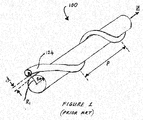
- the '008 application teaches an optical fiber 100 having a first, centrally located and large diameter core 122 for propagating power and a side core 124 spaced from (such as by distance d) and in optical proximity of the central core 122.
- the side core 124 winds around the central core 122 and couples to higher order modes of the central core 122.
- the higher order modes are attenuated due to the bend loss induced by the winding of the side core 124.
- An optical cladding (not shown in FIGURE 1 ) surrounds the cores 122 and 124 and occupies the space between them.
- the winding can be characterized by a pitch P.
- the cladding comprises a material having a lower index of refraction than an index of refraction of material comprised by a core.
- the '008 publication discloses a method of manufacture of such an optical fiber comprising drawing while rotating a fiber preform having a central core and an off-center side core.
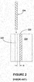
- the '008 publication is understood to teach that an initial preform 200 having a single central core 222 is drilled to form a hole 220 for insertion of a side core 224.
- the side core 224 can be selected from premanufactured glass rods having a predetermined dopant composition.
- the preform having the side core 224 inserted in the hole 220 is then heated to collapse any air gaps.
- the preform having the side core can be drawn to a fiber while rotating the preform about an axis passing through the central core 222 such that the in resultant drawn fiber the side core winds about the central core, as shown in FIGURE 1 .
- US 5 452 394 A relates to a circular-polarization maintaining fiber structure, containing a stress-applying filament whirling around a central core.
- the preform for making such an optical fiber has a stress-applying rod put off-axis inside an otherwise conventional preform.
- desirable operation of the fiber shown in FIGURE 1 can require a very small spacing d between the side core 124 and the central core 122, and hence a very small spacing S between the core 222 and drilled hole 220 of FIGURE 2 if a preform is to be made as taught in the '008 published application.
- a very small spacing S can be problematic, as the central core 222 can be damaged during drilling, or the preform otherwise rendered unusable.
- drilling close to the core can cause crack propagation or shattering, rendering the preform less desirable or undesirable for use. Yield, an important consideration in a commercial endeavor, can be reduced unacceptably.
- Applicants teach herein preforms and methods of making such preforms to make fiber that can reduce the number of holes to be drilled to receive side cores or that can avoid altogether the need for drilling a hole to receive a side core.
- Applicants discovered that the practical restrictions on shaping, such as machining, a preform to within a certain distance of a core to be less onerous.
- the invention can provide an optical fiber preform extending in a longitudinal direction for drawing an optical fiber therefrom having a first core and a second core winding about a the first core, where the preform can comprise a unitary core rod comprising a first core and a cladding disposed about the core; an arrangement of elongate members forming a ring disposed about the core rod; a second core comprising at least one of the elongate members of the arrangement forming the ring; and a elongate tubular region (e.g., a commercially available substrate tube) disposed about the arrangement of elongate members.
- a unitary core rod comprising a first core and a cladding disposed about the core
- an arrangement of elongate members forming a ring disposed about the core rod
- a second core comprising at least one of the elongate members of the arrangement forming the ring
- a elongate tubular region e.g., a commercially available substrate tube
- the preform can be constructed and arranged such that the preform can be drawn with rotation about an axis passing through the first core to provide the fiber wherein a first core of the fiber is multimode at a selected wavelength of operation and a second core of the fiber is spaced from and winds around the first core of the fiber and has a selected longitudinal pitch and wherein at the wavelength of operation the second core of the fiber can couple to a higher order mode of the first core of the fiber and increases the attenuation thereof relative to the fundamental mode of the first core of the fiber.
- the optical fiber preform can comprise an outer perimeter bounding the cross section of the optical fiber preform and defining the geometrical center of the preform.
- the first core can comprise a cross sectional area within which the geometrical center lies.
- the core rod can comprise a diameter and the thickness of the cladding of the core rod is no greater than 15% of the diameter of the core rod.
- the core rod can comprise a diameter and the thickness of the cladding of the core rod is no greater than 10% of the diameter of the core rod.
- At least some of the elongate members of the arrangement of elongate members can be solid rods.
- the cladding of the core rod can be substantially solid.
- the optical fiber preform comprises another elongate tubular region interposed between the arrangement of elongate members and the core rod.
- the optical fiber preform comprises another region (e.g., the cross section of a tube) disposed about the arrangement of elongate members.
- the optical fiber preform can comprise a third core comprising a different one of the elongate members than the side core.
- the host glass of the optical fiber preform can be silica glass.
- the present invention also involves methods. For example, in one aspect, there is provided a method of fabricating an optical fiber preform extending in a longitudinal direction for drawing an optical fiber therefrom having a first core and a second core winding about the first core.
- the method can comprise providing a first elongate member having when viewed in cross section an outer perimeter having a first substantially straight length, the first elongate member further including a core within the outer perimeter of the first elongate member; providing a second elongate member having when viewed in cross section an outer perimeter having a second substantially straight length and a second core within the outer perimeter of the second elongate member; and arranging the preform such that the first substantially straight length faces the second substantially straight length.
- the preform can be further constructed and arranged such that the preform is drawn with rotation about a longitudinal axis passing through the first core to provide the fiber wherein the first core of the fiber is multimode at a selected wavelength of operation and the second core of the fiber is spaced from and winds around the first core of the fiber and has a selected longitudinal pitch and wherein at the wavelength of operation the second core of the fiber couples to a higher order mode of the first core of the fiber and increases the attenuation thereof relative to the fundamental mode of the first core of the fiber.
- a vacuum can be applied to the preform during the drawing.
- a substrate such as a substrate tube or rod.
- MCVD Modified Chemical Vapor Deposition
- OLED Outside Vapor Deposition
- the preform can be constructed and arranged to provide a fiber having certain properties.
- a preform is in certain aspects a scale model of the fiber to be drawn and hence is designed accordingly. Therefore, given the disclosure herein, it is considered that one of ordinary skill in the art can construct and arrange a preform so as to provide fibers as described herein.
- a preform is constructed and arranged so as to provide a fiber having a first core having a diameter of approximately 35 microns and a numerical aperture (NA) relative to its cladding of approximately 0.07.
- the spacing d can comprise approximately 2 microns and the side core can have a diameter of approximately 12 microns and a NA of approximately 0.09 relative to the cladding.
- the pitch P can comprise about 6.2 mm.
- the attenuation for at least one higher order mode is understood to be 10-100 dB/meter greater than the attenuation of the fundamental mode LP 01 at (or for wavelengths greater than) a selected wavelength of operation, such as, for example, 1550 nanometers.
- the attenuation of several higher order modes e.g., LP 11 , LP 21 , LP 02 ), or even of all higher order modes, can be 10 to 100 dB/meter higher than the attenuation of the fundamental mode at a selected wavelength of operation.
- the loss of the fundamental mode, at, for example, the same wavelength of operation can be less than 1 dB/meter, or can be less than 0.5 dB/meter or can even be less than 0.4 dB/meter.
- the first core of the fiber is usually multimode at the wavelength of operation.
- the first core can have a V-number of greater than 2.405 at the wavelength of operation (multimode and V-number in this context meaning as considered as if the side core or cores were absent, as the side core or cores in practice can make the fiber act as substantially single moded (in the fundamental mode) or as a fiber having a V-number less than 2.405).
- the first core can have a diameter of greater than or equal to 10 microns, greater than or equal to 12 microns, or greater than or equal to 15 microns.
- the primary or the side core can have a NA of less than or equal to 0.12, a NA of less than or equal to 0.10, or a NA less than or equal to 0.08.
- the pitch with which the side core is wound can be less than or equal to 20 mm, less than or equal to 15 mm, less than or equal to 10 mm, less than or equal to 8 mm, or less than or equal to 5 mm.
- the pitch can vary along the length of the fiber.
- One way to accomplish varying the pitch is to change the rate of rotation of the preform and/or the fiber as the fiber is being drawn from the preform.
- the variation in pitch i.e., the difference between the maximum and minimum pitches
- the variation in pitch can be between (i.e., range from) 0.5 mm and 1 mm, can be between 1 mm and 2 mm, or can be between 2 mm and 3 mm.
- Pitch can be a function of the speed with which the fiber is drawn and the rotation rate used during draw.
- FIGURES are schematic and which are not drawn to scale.
- FIGURES are schematic and which are not drawn to scale.
- FIGURE 3 is a cross section of one embodiment of an optical fiber preform 300 , where the cross section is taken perpendicular to a longitudinal axis along which the preform extends.
- the optical fiber preform 300 is formed and then drawn in the process of fabricating an optical fiber, such as the optical fiber 100 of FIGURE 1 , having a first core 122 as well as a side core 124 that winds about the first core 122.
- the optical fiber preform 300 comprises a first core 322 and a second core 324.
- the first and second cores 322 and 324 can form, respectively, the first and side cores 122 and 124 of the optical fiber 100.
- the preform 300 can comprise an outer perimeter 328 bounding the cross section of the optical fiber preform 300 and defining the geometrical center of the preform 300.
- the geometrical center 330 of the outer perimeter 328 is the location determined by the average x coordinate and the average y coordinate of the set of x and y coordinates that describes the perimeter 328 in the cross sectional plane. (For a perfect circle, the geometrical center is what is normally referred to as the center of the circle).
- the first core 322 comprises a cross sectional area (defined by the outer perimeter 334 of the first core 322 ) within which the geometrical center 330 lies.
- the outer perimeter 328 is substantially circular in shape.
- the preform 300 can also comprise first and second regions, 338 and 342, respectively.
- the first region 338 can include an outer perimeter 344 having a first curved length 346 and a first substantially straight length 348.
- the second region 342 can have an outer perimeter 356 having a second substantially straight length 358 facing the first substantially straight length 348.
- the first substantially straight length 348 can be substantially parallel to the second substantially straight length 358.
- the first substantially straight length 348 can be spaced from the second substantially straight length 358.
- the substantially straight lengths are substantially parallel and the second substantially straight length 358 is shown as coextensive with at least part of the first substantially straight length 348.
- the first substantially straight length 348 and the second substantially straight length 358 are contiguous in the embodiment shown in FIGURE 3 .
- the outer perimeter 356 of the second region 342 can include the curved length 359, which can be referred to as the second curved length to distinguish it from the first curved length 346 of the first region 338.
- the preform 300 can include a second core 324 spaced from the first core 322, (where, as is evident to one of ordinary skill in light of the disclosure herein, the spacing between the cores refers to the edge-to-edge distance between the outer perimeters thereof along a diameter passing through the geometric centers of each of the outer perimeters).
- One of the first and second regions 338 and 342 can comprise the second core 324.
- the second region 342 comprises the second core 324.
- the preform 300 can be constructed and arranged such that the preform 300 can be drawn with rotation (See FIGURE 7 and accompanying description) to a fiber, such as the fiber 100 of FIGURE 1 , wherein the first core 122 is multimode at a selected wavelength of operation and the side core 124 is wound about and spaced from the central core 122 and has a selected longitudinal pitch P and such that at the wavelength of operation the side core couples 124 to a higher order mode of the central core 122 and selectively increases the attenuation thereof relative to the fundamental mode of the central core 122 .
- the first curved length 346 of the first region 338 can be characterized by (i.e., substantially conform to) a first radius of curvature R 1 .
- the second curved length 359 of the second region 342 can be characterized by a radius R 2 .
- R 1 and R 2 are typically different in that they can originate from different points and/or can have different lengths. Typically they both originate from different points and have different lengths.
- R 1 typically originates from within the cross sectional area of the first core and R 2 originates from within the cross sectional area of the second core.
- R 1 typically has a greater length than R 2 .
- the preform 300 can include an outer region 360 , which can be annular as shown in FIGURE 3 and which can be a tube, disposed about the first region 338 and the second region 342.
- the tube can have the inner perimeter 362 and the outer perimeter of the tube can be the outer perimeter 328 of the preform 300.
- the inner perimeter can be contiguous with at least part of the curved lengths 346 and 359.
- the outer region 360 (as well as the first and second regions, except typically for the cores thereof) can comprise, consist essentially of, or consist of, for example, glass, such as silica glass. As noted elsewhere herein, many techniques are suitable for fabricating all or parts of a preform according to the invention.
- a vapor deposition process such as the Outside Vapor Deposition process, described elsewhere herein, can be used in forming all or part of the preform 300, including fabricating the outer region 360.
- glass soot comprising a suitable index of refraction (e.g., lower than an index of refraction of the material of the first and second regions, 338 and 342, disposed about the cores of those regions), can be deposited over the first and second regions 338 and 342. The soot is then consolidated to form a clear glass.
- the preform 300 can comprise glass tubes or rods, selected ones of which are designated by reference numeral 364.
- the tubes or rods can be sized (e.g., have diameter selected) to fill the gaps between the inner perimeter 362 of the tube 360 and the curved length 359 of the perimeter 356 of the second region 342 to help prevent voids or inclusions in fiber drawn from the preform.
- the outer region 360, the first and second regions 338 and 342 and the tubes or rods 364 can comprise substantially similar material, such as, for example, silica glass.
- the outer perimeter 328 of the preform 300 can comprise a diameter, indicated by arrows 393, that intersects the first and second cores, 322 and 324, and that is substantially perpendicular to one or both of the substantially straight lengths 348 and 358.
- the first and second regions, 338 and 342, such as when arranged in the preform 300, can comprise the diameter indicated by reference numerals 395.
- the diameter 395 can intersect the first and second cores, 322 and 324.
- the diameter 395 can be substantially perpendicular to one or both of the substantially straight lengths 348 and 358 and/or can be the maximum diameter that can be taken across the first and second regions 334 and 342.
- the diameter 395 can be coextensive with at least part of the diameter 393.
- FIGURE 4 is a cross section of another embodiment of an optical fiber preform, where the cross section is taken perpendicular to a longitudinal axis along which the preform extends.
- the optical fiber preform 400 comprises a first core 422 and a second core 424, and is in many respects similar to the preform 300 of FIGURE 3 .
- the first and second cores 422 and 424 can form, respectively, the first and centrally located core 122 and the side core 124 of the optical fiber 100.
- the preform 400 can comprise an outer perimeter 428 bounding the cross section of the optical fiber preform 400 and defining the geometrical center of the preform 400.
- the first core 422 comprises a cross sectional area (defined by the outer perimeter 434 of the first core 422 ) within which the geometrical center 430 lies.
- the preform 400 can also comprise first and second regions, 438 and 442, respectively.
- the first region 438 can include an outer perimeter 444 having a first curved length 446 and a first substantially straight length 448.
- the second region 442 can have an outer perimeter 456 having a second substantially straight length 458 facing the first substantially straight length 448.
- the first substantially straight length 448 can be substantially parallel to the second substantially straight length 458.
- the first substantially straight length 448 can be spaced from the second substantially straight length 458.
- the substantially straight lengths are substantially parallel and the second substantially straight length 458 is shown as coextensive with at least part of the first substantially straight length 448.
- the first substantially straight length 448 and the second substantially straight length 458 are contiguous in the embodiment shown in FIGURE 4 .
- the preform 400 can include a second core 424 spaced from the first core 422.
- One of the first and second regions 438 and 442 can comprise the second core 424.
- the second region 442 comprises the second core 424.
- the preform, including the first and second cores 422 and 424, can be constructed and arranged such that the preform 400 can be drawn with rotation to a fiber, such as the fiber 100 of FIGURE 1 , wherein the central core 122 is multimode at a selected wavelength of operation and the side core 124 is wound about and spaced from the central core 122 and has a selected longitudinal pitch P and such that at the wavelength of operation the side core couples 124 to a higher order mode of the central core 122 and selectively increases the attenuation thereof relative to the fundamental mode of the central core 122 .
- the first curved length 446 of the first region 438 can be characterized by (i.e., substantially conform to) a first radius of curvature R 3 .
- the second curved length 459 of the second region 442 can be characterized by a radius R 4 .
- R 3 and R 4 are typically different, that's is, they can originate from different locations and/or can have different lengths.
- the radius R 3 originates from within the cross sectional area of the first core
- the radius R 4 originates from within the cross sectional area of the second core
- the radius R 3 has a longer length than the radius R 4 .
- the preform 400 can include an outer region 460 , which can be the cross section of a tube, disposed about the first region 438 and the second region 442 .
- the region 460 can comprise the inner perimeter 462 and the outer perimeter of the region 460 can be the outer perimeter 428 of the preform.
- the inner perimeter can be contiguous with at least part of one or both of the curved lengths 446 and 459.
- the outer region 460 (as well as the first and second regions, except typically for the cores thereof) can comprise, consist essentially of, or consist of, for example, glass, such as silica glass.
- the outer region can be formed, at least in part, by a vapor deposition process such as, for example, the Outside Vapor Deposition process.
- the preform 400 can comprise glass tubes or rods, the cross sections of selected ones of which are designated by reference numeral 464.
- the tubes or rods can be sized (e.g., have diameter selected) to fill the gaps between the inner perimeter 462 of the tube 460 and the curved length 459 of the perimeter 456 of the second region 442 to help prevent inclusions or voids in fiber drawn from the preform.
- the outer region 460, the first and second regions 438 and 442 and the tubes or rods 464 can all be comprised of, consist essentially of, or consist of substantially similar material, such as, for example, silica glass.
- the preform 400 can include third and fourth regions, 470 and 474, respectively.
- the fourth region 474 can be substantially similar to the third region 470.
- One or both of the third and fourth regions can have a D-shaped cross section.
- the third region 470 can include an outer perimeter 478 having a curved length 480 and a substantially straight length 482.
- the outer perimeter 444 of the first region 438 can include another substantially straight length 484 that is substantially parallel to the substantially straight length 482.
- the substantially straight lengths 482 and 484 are depicted as coextensive, though one of ordinary skill in the art, apprised of the disclosure herein, understands that the substantially straight lengths 482 and 484 can be spaced from each other.
- the embodiment shown in FIGURE 4 can use fewer tubes or rods 464 (if any at all) to fill any gaps between the inner perimeter 462 of the outer region 460 and the outer perimeter 456 of the second region 442.
- the outer perimeter 428 of the preform 400 can comprise a diameter, indicated by arrows 493, that intersects the first and second cores, 422 and 424, and that is substantially perpendicular to one or both of the substantially straight lengths 448 and 458.
- the first and second regions, 438 and 442, such as when arranged in the preform 400, can comprise the diameter indicated by reference numerals 495.
- the diameter 495 can intersect the first and second cores, 422 and 424.
- the diameter 495 can be substantially perpendicular to one or both of the substantially straight lengths 448 and 458 and/or can be the maximum diameter that can be taken across the first and second regions 438 and 442.
- the diameter 495 can be coextensive with at least part of the diameter 493.
- the outer regions 360 and 460 which can be the cross sections of commercially available substrate tubes, surround the regions (e.g., the first, second third and fourth region and the regions 364 and 464 corresponding to rods or tubes) so as to hold them together.
- the regions shown in FIGURE 3 and 4 as surrounded by the outer region can be fused to each other such that the outer region need not be included.
- the outer perimeter of the preform is thus made up of the appropriate lengths of the boundaries of the various regions. Typically it is desirable that the outer perimeter be substantially circular. If the preform is to be rotated during draw, it can be advantageous to balance of the preform about the longitudinal axis so as to avoid undue vibration during draw.
- the outer region can be included, as shown in FIGURES 3 and 4 , and the first and second regions fused together, including fusing to the outer region via, for example, heating.
- the outer perimeter of the second region 442 can include at least one substantially straight length that is substantially parallel to the straight length 482 of the outer perimeter 478 of the third region 470.
- the outer perimeter of the second region 442 also includes a substantially straight length that is substantially parallel to a substantially straight length of the fourth region 474.
- a preform can include additional regions.
- the first region 438 could comprise two regions with a vertical boundary between them, located, for example, to the left of the first core 422.
- the region including the first core 422 would include a perimeter having only substantially straight lengths. Such considerations apply equally to the second region 442.
- FIGURES 5A-5E schematically illustrate steps that can be employed in fabricating one or both of the preforms of FIGURES 3 and 4 .
- Each of FIGURES 5A through 5E is a cross sectional view, taken along a longitudinal axis, of an elongate member that can be used to form a preform to draw an optical fiber having first and side cores.
- each member can be considered a preform as it could be drawn to form an optical fiber, though the resultant fiber would have just a single, centrally located core.
- FIGURE 5A shows an elongate member 501 that includes a core 522 and a cladding 537 disposed about the core 522 .
- the elongate member 501 can include an outer perimeter 544 that substantially conforms to a circle having the radius R 5 .
- the elongate member 501 can be shaped, such as by being machined (e.g., grinding) to remove material to the right of the dotted line A in FIGURE 5A , such that the outer perimeter 544 of the elongate member 501 includes the curved length 546 and the substantially straight length 548 , as shown in FIGURE 5B .
- the core 522 remains within the outer perimeter 544 , and the edge of the core is shown as being spaced from the substantially straight length 548 by the distance S1.
- FIGURE 5C shows a second elongate member 503 that includes a core 524 and a cladding 547 disposed about the core 524 .
- the second elongate member 503 can include an outer perimeter 556 that can substantially conform to a circle having the radius R 6 .
- One of the radii R 5 and R 6 is typically different than the other of the radii, such as by being smaller or larger.
- the radius R 6 is smaller than the radius R 5 .
- the elongate member 503 can be shaped, such by being machined (e.g., grinding) to remove material to the left of the dotted line B in FIGURE 5C , such that the outer perimeter 556 of the elongate member 503 includes the curved length 559 and the substantially straight length 558, as shown in FIGURE 5D .
- the core 524 remains within the outer perimeter 556, and the edge of the core is shown as being spaced from the substantially straight length 558 by the distance S2.
- the first elongate member 501 and the second elongate member 503 can be arranged as illustrated in FIGURE 5E , such that the substantially straight length 548 of the first elongate member 501 faces the substantially straight length 558 of the second elongate member 503.
- the substantially straight length 548 can be substantially parallel to the substantially straight length 558.
- the substantially straight length 548 can be spaced from the substantially straight length 558.
- the substantially straight length 548 is substantially parallel to and contiguous with the substantially straight length 558.
- the substantially straight length 558 is shown as coextensive with part of the substantially straight length 548 in FIGURE 5E .
- the arrangement shown in FIGURE 5E can be disposed within an outer region, such as the tube 360 of FIGURE 3 , along with rods or tubes to fill gaps as desired, to form the preform 300 having the cross section shown in FIGURE 3 .
- One way to arrange the elongate members 501 and 503 as shown in FIGURE 5E is to fuse the elongate member 501 to the elongate member 503.
- the various regions of a preform according to the invention can be cross sections of various elongate members. According to one practice of the invention, it can be advantageous in certain instances to fuse some or all of the members together prior to drawing an optical fiber from the preform. However, such fusing is not considered necessary.
- members can simply be arranged in proximity to each other within a tubular outer member (e.g., the member having the cross section 360 in FIGURE 3 ) as shown in FIGURES 3 and 4 .
- the term preform is not limited to the particular, final structure from which a particular fiber is drawn. For example, in the instance where all of the regions or members are fused, the unfused arrangement is also considered a preform.
- An outer region can be disposed about the arrangement 505 using an Outside Vapor Deposition process, as noted above.
- elongate members 501 and 503 can be shaped such that material above the dotted line C and below the dotted line D in FIGURE 5B is removed from elongate member 501 and material above the dotted line E and below the dotted line F in FIGURE 5D is removed from elongate member 503.
- the outer perimeter of each of the elongate members 501 and 503 now includes two additional substantially straight lengths, with, in the case of the elongate member 501, the two additional straight lengths each being substantially parallel to each other and hence substantially perpendicular to the substantially straight length 548.
- each of the two additional substantially straight lengths is substantially parallel to each other and substantially perpendicular to the substantially straight length 558.
- the elongate members can be arranged with additional D shaped elongate members (which form the regions 470 and 474 ) and disposed within a suitable tubular outer region 460 to form the preform 400 shown in FIGURE 4 .
- Tubes or rods 464 can be included as appropriate, and may not be needed at all in certain practices of the invention.
- Elongate members suitable to provide D-shaped regions 470 and 474 can be formed from circular elongate members that are shaped to remove material and provide the outer perimeters of the regions with appropriate substantially straight lengths (e.g., the substantially straight lengths 482 and 486 shown in FIGURE 4 .
- the additional elongate members can be drilled to form a hole to accommodate additional side cores, such as, for example, the side core 491 shown in FIGURE 4 .
- additional side cores can be used.
- the primary and side cores of preforms can be constructed and arranged such that the preform can be drawn with rotation to a fiber wherein the first core is multimode at a selected wavelength of operation and the second core is spaced from and winds around the first core so as to have a selected longitudinal pitch and such that at said wavelength of operation said side core couples to a higher order mode of the first core and selectively increases the attenuation thereof relative to the fundamental mode of the first core.
- the spacing S3 indicated in FIGURE 5E is substantially equal to the sum of S1 and S2. Applicants consider that, for a spacing between the first and the side cores of less than a certain value, it is safer, in terms of the likelihood of damage to the preform, to shape the preform as shown in FIGURES 5A-5E to achieve the spacing S3 than it is to drill a hole next to the core 222 so as to achieve a spacing S (shown in FIGURE 2 ) that is substantially the same as S3.
- the geometrical center defined by the outer perimeter of the member lies within the cross section area of a core of the member (e.g., within the cross section area of the core 522 or 524, where the cross sectional area core is that area within the outer perimeter of the core).
- the core is typically located substantially at the center of the elongate member (other cores, such as, for example, additional side cores, could be added to the member, such as by drilling a hole and inserting a core rod into the hole).
- the elongate members 501 and 503 are each typically made of glass, such as, for example, silica glass.
- the claddings 537 and 547 can each consist essentially of, or consist of undoped silica glass.
- the elongate members can be formed by a variety of general preform fabrication processes known in the art of fiber optic preparation, including, but not limited to, MCVD, OVD, VAD, and the like.
- FIGURE 6 is a cross section of yet a further embodiment of an optical fiber preform according to the present invention.
- the optical fiber preform 600 comprises a first core 622 and a side core 624.
- the first core comprises an outer perimeter 634.
- the preform 600 comprises an outer perimeter 628 bounding the cross section of the optical fiber preform 600 and defining the geometrical center of the preform.
- the geometrical center can lie within the cross sectional area of the first core 622, which is the area within the outer perimeter 634 of the first core 622.
- the cladding 637 can be disposed about the core 622 and can have an annular shape, as shown in FIGURE 6 .
- the first core 622 and cladding 637 can be part of a core rod having as its outer perimeter the outer perimeter 644 of the cladding 637.
- the core rod can be unitary, that is, the first core 622 can adhereingly contact the cladding 637.
- One way to form such a unitary core rod is to deposit core material on the inside of a tube, such as by using the aforementioned MCVD technique, where at least part of the tube can form at least part of the cladding.
- the tube can be etched or machined to have its outside diameter reduced, if necessary, to provide a core rod having a selected outside diameter.
- the cladding 637 will form a rather thin layer around the first core 622 of the unitary core rod.
- the thickness T of the cladding is no greater than 15% of the diameter D 1 of the first core 622 , no greater than 10% of the diameter D 1 , or no greater than 8% of the diameter D 1 .
- the first core 622 and the cladding 637 of the core rod can be substantially solid, that is, substantially free of longitudinally extending voids, such as would be the case, for example, for the cladding 637 if it were formed by packing rods or tubes together (such as is often done in forming a preform for photonic bandgap or microstructured cladding fiber).
- the preform 600 can include a first annular region 673, having the outer perimeter 683, disposed about the annular arrangement of elongate members 653, and a second annular region 660, having the outer perimeter 628, disposed about the first annular region 673.
- the annular regions can be cross sections of first and second substrate tubes, respectively, as is appreciated by one of ordinary skill in the art, in light of the disclosure herein. If available a single tube having the appropriate thickness can be used instead of two tubes. As noted above in conjunction with the discussion of FIGURES 3, 4 and 5A-5E , all or selected parts of the preform 600 can be fused prior to drawing optical fiber from the preform.
- a preform according to the invention can be drawn to a fiber while rotating one or both of the fiber and the preform. Preferably, only the preform is rotated.
- FIGURE 7 schematically illustrates drawing an optical fiber from a preform while rotating the preform.
- the motor 711 rotates, as indicated by reference numeral 715, the preform 717.
- the furnace 725 heats the end 727 of the preform 711 to facilitate drawing of the fiber 731.
- the coating apparatus 741 can add a coating to the fiber that can serve to protect the fiber as well as a cladding, depending, as is known in the art, on the characteristics of the cladding (e.g., the refractive index of the cured cladding relative to the refractive index of the region of the optical fiber to which the coating is applied.
- the coating apparatus 741 shown in FIGURE 7 includes nested reservoirs 745 and 747 for applying a dual coating to the optical fiber 731.
- the inner coating reservoir can apply a soft coating and the outer coating reservoir can apply a hard coating over the soft coating.
- a UV lamp (not shown) typically cures the coatings before the fiber 731 is wound on a spool.
- the coating has a lower index to confine pump light to the region of the fiber surrounded by the cured coating.
- Such fibers are known in art as "cladding pumped” or “double clad” fibers.
- the region of the fiber surrounded by the coating can have a non-circular outer perimeter.
- the outer region 360 of FIGURE 3 or the outer region 460 of FIGURE 4 can be shaped, such a by grinding, to have a non-circular (e.g., a flat can be ground into the outer perimeter 328 of outer region 360 to provide the desired non - circularity.
- a vacuum can be desirable to apply a vacuum to a preform, such as, for example, to the region of the preform 300 of FIGURE 3 inside of the inner perimeter 362 of the outer region 360, while drawing the preform to a fiber, as is know in the art.
- a preform can be made using one or more of a variety of suitable methods, including vapor phase methods such as outside vapor deposition (OVD), Modified Chemical Vapor Deposition (MCVD), Chemical Vapor Deposition (CVD) and Vapor Axial Deposition (VAD) and combinations thereof.
- Vapor phase methods usually employ suitable gas precursors that are introduced to a hot substrate, a hot zone, or directly into a flame. The latter technique is known as flame hydrolysis.
- precursor gases are introduced to a flame to form soot that is deposited on a substrate, such as the inside, outside or end of a tube or rod. The soot is subsequently heated and sintered using an oven or furnace.
- the tube or rod can form a part of the resultant optical fiber preform, or can be removed.
- the OVD and VAD processes typically involve flame hydrolysis.
- precursor gases are introduced to a hot zone and/or a heated substrate, which can again be a tube or rod.
- MCVD lathes and of draw towers is Nextrom Technologies of Finland. Nextrom Technologies has a U.S. office located at 2150 Northmont Pkwy - suite F, Duluth, GA 30096.
- Each of the foregoing techniques can include one or more overjacketing steps wherein a member formed by one of the foregoing techniques is overjacketed with a glass tube that will typically form additional cladding. Overjacketing can be used to add a region, such as the region 360 of FIGURE 3 , to a preform.
- Glass tubes are available in variety of sizes, and are often specified by an inner and outer diameter. Tubes can be etched to adjust the outer and inner diameters as necessary to facilitate various desired glass working steps, as is know in the art. Glass tube and rods suitable for deposition of soot, the deposition of glass, or for use as an overjacket are available from Heraeus Amersil, Inc. 3473 Satellite Boulevard., Duluth, GA, 30096.
- the glass rods and/or tubes can include various types of glasses, such as, for example, silica glass, borosilicate glass, a fluorinated silica glass, a phosphate glass and other types of glasses.
- Rods and tubes can also be made by casting molten glass into appropriate molds.
- one technique for providing a tube is to cast molten glass into a mold that is spun on a lathe. Centrifugal force causes the molten glass to press outward again the walls of the mold such that the glass cools to form a tube.
- Rods and tubes can also be made by Sol-Gel techniques.
- silica is the host glass of the optical fiber or preform, to which other materials are added.
- Common dopant materials used with silica include aluminum, boron, fluorine, germanium, phosphorus, titanium, the rare earths (such as, for example, erbium, ytterbium and lanthanum) and transition metals, which can be used to provide selected attenuation.
- other types of glass such as, for example, chalcogenide glass, ZBLAN glass, phosphate glass, fluoride glass, germanium based glass and the like, as well as any of the single crystal or polycrystalline materials such as thallium bromoiodide, germanium, zinc selenide, and the like, may be found suitable.
- an optical fiber according to the invention may comprise any of these or other materials, or variants thereof, singly or in combination for the core, cladding or other layers.
- Dopants can be added using, for example, vapor phase processes and/or solution doping processes.
- FIGURE 8 schematically illustrates in more detail an example of the preform 300 illustrated in FIGURE 3 .
- the reference numerals of FIGURE 8 correspond to those used in conjunction with FIGURE 3 .
- the suffix "A" is added to the reference numerals of FIGURE 8 .
- a full description corresponding to each of the reference numerals of FIGURE 8 is not repeated here, and for those not discussed here reference may be made to the discussion accompanying FIGURE 3 and the reference numeral as used there without the suffix. Similar considerations apply to other FIGURES below, as will be readily appreciated by one of ordinary skill in the art.
- the first region 338A can comprise an outer perimeter 344A having a first curved length 346A that is characterized by a radius of curvature R 1A that is substantially the same as R 2A , where the outer perimeter 356A of the second region 342A includes a second curved length 359A that is characterized by the radius of curvature R 2A . That is, the radius of curvature R 1A and the radius of curvature R 2A can originate from the substantially the same location (e.g., the geometrical center of the outer perimeter 334A of the first core 322A ) and have substantially the same length.
- the first and second curved lengths 346A and 359A can form substantially the entire outer perimeter of the first and second regions, which outer perimeter can be the outer perimeter 328A of the preform, as the substantially circular nature of the outer perimeter of the first and second regions can obviate the need to dispose the region 360A about the first and second regions.
- any gaps between the outer perimeters of the first and second regions and the inner perimeter of the outer region 362A can be considerably reduced in size (e.g., see the gap between the outer perimeter 356 of the second region 342 and the inner perimeter 362 of the outer region 360 as illustrated in FIGURE 3 ).
- the preform 300A can be fabricated generally according to the procedures shown in FIGURES 5A through 5E and the accompanying description thereof provided herein.
- the elongate member 503, which can form region 342A shown in FIGURE 8 is shaped to have an outer perimeter having a curved section substantially characterized by the radius of curvature of R 2A .
- the elongate member 503A includes a core 524A, a cladding 547A, and an outer perimeter 556A that substantially conforms to a circle having a radius R 6A , where R 6A is longer than R 2a .
- the distance C is the distance between the geometric centers of the outer perimeters of the typically circular cores 322A and 324A taken along a line through the centers (e.g., the line H in FIGURE 9 ).
- the material between the outer perimeter 556A and the dotted line 559A namely the material of region 913 of FIGURE 9 , is removed.
- the dotted line 559A substantially conforms to a radius of curvature R 2A where the radius originates at location 919 spaced along a diameter of the outer perimeter 556A by a distance C from the geometric center of the outer perimeter of the core 524A.
- the elongate member 503A is made from an axially symmetric process and has a circular core 524A, and hence the aforementioned geometric center is simply the center of the circular core.
- the material above the line B is then removed, such as by grinding or etching so as to form the second elongate member 503A shown in FIGURE 10 having an outer perimeter 556A comprising the substantially straight length 558A and the curved length 556B that is characterized by the radius R 2A .
- the first elongate member 501 can be arranged with the second elongate member 503A such that the substantially straight lengths are contiguous and the entire outer perimeter thereof is characterized by a radius R 2A .
- the line B shown in FIGURE 9 and the line A shown in FIGURE 5A can be selected such that the edges of the cores of the elongate members are spaced by the appropriate distance (e.g., the distance S3 shown in FIGURE 5E ) when the first and second elongate members are arranged as shown to form the preform 300A.
- This distance is in turn selected to provide the desired spacing d (see FIGURE 1 ) in the resultant fiber drawn from the preform with rotation, as illustrated schematically in FIGURE 7 .
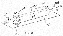
- FIGURE 11 illustrates one technique for removing the region 913 from the elongate member 503A of FIGURE 9 so as to provide the curved length 556B shown in FIGURE 10 .
- the elongate member 503A is mounted on a polishing or grinding apparatus so as to pivot about the axis Z shown in FIGURE 11 .
- the axis Z can be moved downward, as indicated by arrow 1103, such that the elongate member 503A contacts the grinding or polishing surface 1105.
- Axis Z can be selected so as to pass through locations 1119, on each end face of the elongate member, corresponding to location 919 shown in FIGURE 9 .
- Arrows 1101 indicate the pivoting motion about the axis Z.
- the axis Z can be moved downward until it is spaced from the grinding or polishing surface by a distance substantially equal to R 2A .
- reference numeral 1105 can represent the surface of an etchant bath.
- FIGURE 12 illustrates another example of a preform 300B.
- the material above line E can removed from elongate member 503A so that elongate region 503A may form second region 342B of the preform 300B of FIGURE 12 .
- the second region 342B can comprise the outer perimeter 356B having a substantially straight length 1284 formed by the removal of the material above line E in FIGURE 10 .
- the preform 300B can comprise a third region 1270 comprising a third core 1291 that is spaced from the cores 322B and 324B.
- the spacings between the cores can be selected such the resultant spacings between the corresponding cores of the fiber drawn from the preform can, as taught in the '008 application noted above, attenuate higher order modes in the fiber core formed from the core 322B of the preform 300B.
- the third region 1270 can be derived from an elongate member according to the teachings herein.
- the outer perimeter of the third region 1270 can comprise the curved length 1280, which can be characterized by a radius R 12 that has a shorter length than the radius R 1B , where the outer perimeters of the first and second regions each include curved lengths characterized by the radius R 1B .
- FIGURE 12 corresponds to those used in conjunction with FIGURE 3 .
- the suffix "B' is added to the reference numerals of FIGURE 12 .
- not all the reference numerals of FIGURE 3 are provided with a corresponding reference numeral in FIGURE 12 and not all those shown are discussed here.
Landscapes
- Engineering & Computer Science (AREA)
- Chemical & Material Sciences (AREA)
- Materials Engineering (AREA)
- Geochemistry & Mineralogy (AREA)
- Manufacturing & Machinery (AREA)
- General Life Sciences & Earth Sciences (AREA)
- Life Sciences & Earth Sciences (AREA)
- Organic Chemistry (AREA)
- Physics & Mathematics (AREA)
- Optics & Photonics (AREA)
- Electromagnetism (AREA)
- General Physics & Mathematics (AREA)
- Microelectronics & Electronic Packaging (AREA)
- Plasma & Fusion (AREA)
- Manufacture, Treatment Of Glass Fibers (AREA)
Description
- The present invention relates to fiber optic articles, such as optical fibers, optical fiber preforms and the like, and methods for making fiber optic articles.
- Fiber lasers and fiber amplifiers capable of handling higher powers are of considerable interest. Unfortunately, non-linear effects, such as Simulated Brillioun Scattering (SBS) and Stimulated Raman Scattering (SRS) can limit the power output of fiber lasers and amplifiers to lower powers. Because optical fiber has a rather small cross section, the light propagated by the fiber is rather concentrated and hence, at higher power operation, the light can reach a power density that exceeds the power density threshold for the onset of SBS and/or SRS.
- Fibers having a larger diameter core can lower the power density and delay the onset of SBS or SRS, thereby allowing higher power operation. However, a core having a larger diameter is not typically single mode. Because the larger diameter core will support modes in addition to the fundamental mode, the fiber provides a lower beam quality (i.e., a lower M2 factor) than a single mode fiber. Higher beam quality is important in many applications. Certain techniques are known for attenuating and/or limiting the excitation of such higher order modes such that a larger core fiber can still provide good beam quality.
- Known techniques include coiling of the fiber to selectively induce bend loss into the higher order modes, such as is taught in
U.S. Patent No. 6,496,301 , entitled "Helical Fiber Amplifier".US 2006/0024008 A1 , entitled "Composite Waveguide", teaches another technique. With reference toFIGURE 1 , the '008 application teaches anoptical fiber 100 having a first, centrally located and large diameter core 122 for propagating power and aside core 124 spaced from (such as by distance d) and in optical proximity of the central core 122. Theside core 124 winds around the central core 122 and couples to higher order modes of the central core 122. The higher order modes are attenuated due to the bend loss induced by the winding of theside core 124. An optical cladding (not shown inFIGURE 1 ) surrounds thecores 122 and 124 and occupies the space between them. The winding can be characterized by a pitch P. Typically the cladding comprises a material having a lower index of refraction than an index of refraction of material comprised by a core. - The '008 publication discloses a method of manufacture of such an optical fiber comprising drawing while rotating a fiber preform having a central core and an off-center side core. With reference to
FIGURE 2 , the '008 publication is understood to teach that aninitial preform 200 having a singlecentral core 222 is drilled to form ahole 220 for insertion of aside core 224. Theside core 224 can be selected from premanufactured glass rods having a predetermined dopant composition. The preform having theside core 224 inserted in thehole 220 is then heated to collapse any air gaps. The preform having the side core can be drawn to a fiber while rotating the preform about an axis passing through thecentral core 222 such that the in resultant drawn fiber the side core winds about the central core, as shown inFIGURE 1 . -
US 5 452 394 A relates to a circular-polarization maintaining fiber structure, containing a stress-applying filament whirling around a central core. The preform for making such an optical fiber has a stress-applying rod put off-axis inside an otherwise conventional preform. - While the foregoing applications, patents or techniques may represent an improvement in the art, each can have drawbacks or limitations in certain circumstances. Accordingly, it is an object of the present invention to provide optical articles and methods for fabricating such optical articles that address one or more of the drawbacks or deficiencies of the prior art.
- In certain instances, desirable operation of the fiber shown in
FIGURE 1 can require a very small spacing d between theside core 124 and the central core 122, and hence a very small spacing S between thecore 222 and drilledhole 220 ofFIGURE 2 if a preform is to be made as taught in the '008 published application. A very small spacing S can be problematic, as thecentral core 222 can be damaged during drilling, or the preform otherwise rendered unusable. For example, due to the stresses (because the material of the core is typically different than that of the cladding material, formed by the initial tube), drilling close to the core can cause crack propagation or shattering, rendering the preform less desirable or undesirable for use. Yield, an important consideration in a commercial endeavor, can be reduced unacceptably. - Accordingly, Applicants teach herein preforms and methods of making such preforms to make fiber that can reduce the number of holes to be drilled to receive side cores or that can avoid altogether the need for drilling a hole to receive a side core. In addressing the difficulty of drilling a hole close to the core, Applicants discovered that the practical restrictions on shaping, such as machining, a preform to within a certain distance of a core to be less onerous.
- In one aspect, the invention can provide an optical fiber preform extending in a longitudinal direction for drawing an optical fiber therefrom having a first core and a second core winding about a the first core, where the preform can comprise a unitary core rod comprising a first core and a cladding disposed about the core; an arrangement of elongate members forming a ring disposed about the core rod; a second core comprising at least one of the elongate members of the arrangement forming the ring; and a elongate tubular region (e.g., a commercially available substrate tube) disposed about the arrangement of elongate members. The preform can be constructed and arranged such that the preform can be drawn with rotation about an axis passing through the first core to provide the fiber wherein a first core of the fiber is multimode at a selected wavelength of operation and a second core of the fiber is spaced from and winds around the first core of the fiber and has a selected longitudinal pitch and wherein at the wavelength of operation the second core of the fiber can couple to a higher order mode of the first core of the fiber and increases the attenuation thereof relative to the fundamental mode of the first core of the fiber.
- The optical fiber preform can comprise an outer perimeter bounding the cross section of the optical fiber preform and defining the geometrical center of the preform. The first core can comprise a cross sectional area within which the geometrical center lies. In one practice of the invention the core rod can comprise a diameter and the thickness of the cladding of the core rod is no greater than 15% of the diameter of the core rod. In one practice of the invention the core rod can comprise a diameter and the thickness of the cladding of the core rod is no greater than 10% of the diameter of the core rod. At least some of the elongate members of the arrangement of elongate members can be solid rods. The cladding of the core rod can be substantially solid. The optical fiber preform comprises another elongate tubular region interposed between the arrangement of elongate members and the core rod. The optical fiber preform comprises another region (e.g., the cross section of a tube) disposed about the arrangement of elongate members. The optical fiber preform can comprise a third core comprising a different one of the elongate members than the side core. The host glass of the optical fiber preform can be silica glass.
- The present invention also involves methods. For example, in one aspect, there is provided a method of fabricating an optical fiber preform extending in a longitudinal direction for drawing an optical fiber therefrom having a first core and a second core winding about the first core. The method can comprise providing a first elongate member having when viewed in cross section an outer perimeter having a first substantially straight length, the first elongate member further including a core within the outer perimeter of the first elongate member; providing a second elongate member having when viewed in cross section an outer perimeter having a second substantially straight length and a second core within the outer perimeter of the second elongate member; and arranging the preform such that the first substantially straight length faces the second substantially straight length. The preform can be further constructed and arranged such that the preform is drawn with rotation about a longitudinal axis passing through the first core to provide the fiber wherein the first core of the fiber is multimode at a selected wavelength of operation and the second core of the fiber is spaced from and winds around the first core of the fiber and has a selected longitudinal pitch and wherein at the wavelength of operation the second core of the fiber couples to a higher order mode of the first core of the fiber and increases the attenuation thereof relative to the fundamental mode of the first core of the fiber.
- A vacuum can be applied to the preform during the drawing.
- Many processes that are advantageous in fabricating preforms include depositing material in an axially symmetric manner on a substrate, such as a substrate tube or rod. As one example, in the Modified Chemical Vapor Deposition (MCVD) process, material is deposited on the inside of a rotating tube that can then be collapsed to form a solid rod. Material deposited on the inside of the tube typically forms all or part of a centrally located core in the solid rod that results from collapsing the tube. Similar considerations apply, for example, to the Outside Vapor Deposition (OVD) process, which can also result in a rod having a central region comprising deposited material surrounded by material of the tube.
- As noted above, the preform can be constructed and arranged to provide a fiber having certain properties. One of ordinary skill in the art understands that a preform is in certain aspects a scale model of the fiber to be drawn and hence is designed accordingly. Therefore, given the disclosure herein, it is considered that one of ordinary skill in the art can construct and arrange a preform so as to provide fibers as described herein. In practice, a preform is constructed and arranged so as to provide a fiber having a first core having a diameter of approximately 35 microns and a numerical aperture (NA) relative to its cladding of approximately 0.07. The spacing d can comprise approximately 2 microns and the side core can have a diameter of approximately 12 microns and a NA of approximately 0.09 relative to the cladding. The pitch P can comprise about 6.2 mm.
- For such a fiber, the attenuation for at least one higher order mode (e.g., LP11) is understood to be 10-100 dB/meter greater than the attenuation of the fundamental mode LP01 at (or for wavelengths greater than) a selected wavelength of operation, such as, for example, 1550 nanometers. The attenuation of several higher order modes (e.g., LP11, LP21, LP02), or even of all higher order modes, can be 10 to 100 dB/meter higher than the attenuation of the fundamental mode at a selected wavelength of operation. The loss of the fundamental mode, at, for example, the same wavelength of operation, can be less than 1 dB/meter, or can be less than 0.5 dB/meter or can even be less than 0.4 dB/meter.
- The first core of the fiber is usually multimode at the wavelength of operation. The first core can have a V-number of greater than 2.405 at the wavelength of operation (multimode and V-number in this context meaning as considered as if the side core or cores were absent, as the side core or cores in practice can make the fiber act as substantially single moded (in the fundamental mode) or as a fiber having a V-number less than 2.405). The first core can have a diameter of greater than or equal to 10 microns, greater than or equal to 12 microns, or greater than or equal to 15 microns. The primary or the side core can have a NA of less than or equal to 0.12, a NA of less than or equal to 0.10, or a NA less than or equal to 0.08.
- In practice, the pitch with which the side core is wound can be less than or equal to 20 mm, less than or equal to 15 mm, less than or equal to 10 mm, less than or equal to 8 mm, or less than or equal to 5 mm. The pitch can vary along the length of the fiber. One way to accomplish varying the pitch is to change the rate of rotation of the preform and/or the fiber as the fiber is being drawn from the preform. In practice, the variation in pitch (i.e., the difference between the maximum and minimum pitches) can be less than or equal to 0.5 mm, less than or equal to 1 mm, less than or equal to 2 mm, or less than or equal to 5 mm. In other practices, the variation in pitch can be between (i.e., range from) 0.5 mm and 1 mm, can be between 1 mm and 2 mm, or can be between 2 mm and 3 mm. Pitch can be a function of the speed with which the fiber is drawn and the rotation rate used during draw.
- Further advantages, novel features, and objects of the invention will become apparent from the following detailed description of non-limiting embodiments of the invention when considered in conjunction with the accompanying FIGURES, which are schematic and which are not drawn to scale. For purposes of clarity, not every component is labeled in every one of the following FIGURES, nor is every component of each embodiment of the invention shown where illustration is not considered necessary to allow those of ordinary skill in the art to understand the invention.
-
-
FIGURE 1 schematically illustrates a prior art optical fiber having a central core and a side core winding about the central core; -
FIGURE 2 schematically illustrates a prior art method of making a preform from which the fiber ofFIGURE 1 can be drawn; -
FIGURE 3 is a cross section of one embodiment of an optical fiber preform; -
FIGURE 4 is a cross section of another embodiment of an optical fiber preform; -
FIGURES 5A-5E schematically illustrates steps that can be employed in fabricating one or both of the preforms ofFIGURES 3 and 4 ; -
FIGURE 6 is a cross section of yet a further embodiment of an optical fiber preform according to the invention; -
FIGURE 7 schematically illustrates drawing an optical fiber from a preform while rotating the preform; -
FIGURE 8 schematically illustrates a cross section of another embodiment of an optical fiber preform; -
FIGURE 9 schematically illustrates how an elongate member is to be modified to have a desired shape for use in forming one embodiment of a preform; -
FIGURE 10 schematically illustrates a cross section of an elongate member having the desired shape shown inFIGURE 9 ; -
FIGURE 11 schematically illustrates shaping the elongate member ofFIGURE 9 to change the shape of at least part of the outer perimeter thereof; and -
FIGURE 12 schematically illustrates a cross section of yet an additional embodiment of an optical fiber preform. -
FIGURE 3 is a cross section of one embodiment of anoptical fiber preform 300, where the cross section is taken perpendicular to a longitudinal axis along which the preform extends. Theoptical fiber preform 300 is formed and then drawn in the process of fabricating an optical fiber, such as theoptical fiber 100 ofFIGURE 1 , having a first core 122 as well as aside core 124 that winds about the first core 122. Accordingly, theoptical fiber preform 300 comprises afirst core 322 and asecond core 324. The first andsecond cores side cores 122 and 124 of theoptical fiber 100. - The
preform 300 can comprise anouter perimeter 328 bounding the cross section of theoptical fiber preform 300 and defining the geometrical center of thepreform 300. Thegeometrical center 330 of theouter perimeter 328 is the location determined by the average x coordinate and the average y coordinate of the set of x and y coordinates that describes theperimeter 328 in the cross sectional plane. (For a perfect circle, the geometrical center is what is normally referred to as the center of the circle). Typically, thefirst core 322 comprises a cross sectional area (defined by theouter perimeter 334 of the first core 322) within which thegeometrical center 330 lies. Preferably, theouter perimeter 328 is substantially circular in shape. - The
preform 300 can also comprise first and second regions, 338 and 342, respectively. Thefirst region 338 can include anouter perimeter 344 having a firstcurved length 346 and a first substantiallystraight length 348. Thesecond region 342 can have anouter perimeter 356 having a second substantiallystraight length 358 facing the first substantiallystraight length 348. The first substantiallystraight length 348 can be substantially parallel to the second substantiallystraight length 358. The first substantiallystraight length 348 can be spaced from the second substantiallystraight length 358. In the embodiment shown inFIGURE 3 , the substantially straight lengths are substantially parallel and the second substantiallystraight length 358 is shown as coextensive with at least part of the first substantiallystraight length 348. The first substantiallystraight length 348 and the second substantiallystraight length 358 are contiguous in the embodiment shown inFIGURE 3 . Theouter perimeter 356 of thesecond region 342 can include the curved length 359, which can be referred to as the second curved length to distinguish it from the firstcurved length 346 of thefirst region 338. - The
preform 300 can include asecond core 324 spaced from thefirst core 322, (where, as is evident to one of ordinary skill in light of the disclosure herein, the spacing between the cores refers to the edge-to-edge distance between the outer perimeters thereof along a diameter passing through the geometric centers of each of the outer perimeters). One of the first andsecond regions second core 324. In the embodiment shown inFIGURE 3 , thesecond region 342 comprises thesecond core 324. Thepreform 300 can be constructed and arranged such that thepreform 300 can be drawn with rotation (SeeFIGURE 7 and accompanying description) to a fiber, such as thefiber 100 ofFIGURE 1 , wherein the first core 122 is multimode at a selected wavelength of operation and theside core 124 is wound about and spaced from the central core 122 and has a selected longitudinal pitch P and such that at the wavelength of operation the side core couples 124 to a higher order mode of the central core 122 and selectively increases the attenuation thereof relative to the fundamental mode of the central core 122. - The first
curved length 346 of thefirst region 338 can be characterized by (i.e., substantially conform to) a first radius of curvature R1. The second curved length 359 of thesecond region 342 can be characterized by a radius R2. R1 and R2 are typically different in that they can originate from different points and/or can have different lengths. Typically they both originate from different points and have different lengths. R1 typically originates from within the cross sectional area of the first core and R2 originates from within the cross sectional area of the second core. R1 typically has a greater length than R2. - The
preform 300 can include anouter region 360, which can be annular as shown inFIGURE 3 and which can be a tube, disposed about thefirst region 338 and thesecond region 342. The tube can have theinner perimeter 362 and the outer perimeter of the tube can be theouter perimeter 328 of thepreform 300. The inner perimeter can be contiguous with at least part of thecurved lengths 346 and 359. The outer region 360 (as well as the first and second regions, except typically for the cores thereof) can comprise, consist essentially of, or consist of, for example, glass, such as silica glass. As noted elsewhere herein, many techniques are suitable for fabricating all or parts of a preform according to the invention. A vapor deposition process, such as the Outside Vapor Deposition process, described elsewhere herein, can be used in forming all or part of thepreform 300, including fabricating theouter region 360. For example, glass soot comprising a suitable index of refraction (e.g., lower than an index of refraction of the material of the first and second regions, 338 and 342, disposed about the cores of those regions), can be deposited over the first andsecond regions preform 300 can comprise glass tubes or rods, selected ones of which are designated byreference numeral 364. The tubes or rods can be sized (e.g., have diameter selected) to fill the gaps between theinner perimeter 362 of thetube 360 and the curved length 359 of theperimeter 356 of thesecond region 342 to help prevent voids or inclusions in fiber drawn from the preform. Theouter region 360, the first andsecond regions rods 364 can comprise substantially similar material, such as, for example, silica glass. - The
outer perimeter 328 of thepreform 300 can comprise a diameter, indicated byarrows 393, that intersects the first and second cores, 322 and 324, and that is substantially perpendicular to one or both of the substantiallystraight lengths preform 300, can comprise the diameter indicated byreference numerals 395. Thediameter 395 can intersect the first and second cores, 322 and 324. Thediameter 395 can be substantially perpendicular to one or both of the substantiallystraight lengths second regions diameter 395 can be coextensive with at least part of thediameter 393. -
FIGURE 4 is a cross section of another embodiment of an optical fiber preform, where the cross section is taken perpendicular to a longitudinal axis along which the preform extends. Theoptical fiber preform 400 comprises afirst core 422 and asecond core 424, and is in many respects similar to thepreform 300 ofFIGURE 3 . The first andsecond cores side core 124 of theoptical fiber 100. - The
preform 400 can comprise anouter perimeter 428 bounding the cross section of theoptical fiber preform 400 and defining the geometrical center of thepreform 400. Thefirst core 422 comprises a cross sectional area (defined by theouter perimeter 434 of the first core 422) within which the geometrical center 430 lies. - The
preform 400 can also comprise first and second regions, 438 and 442, respectively. Thefirst region 438 can include anouter perimeter 444 having a firstcurved length 446 and a first substantiallystraight length 448. Thesecond region 442 can have anouter perimeter 456 having a second substantiallystraight length 458 facing the first substantiallystraight length 448. The first substantiallystraight length 448 can be substantially parallel to the second substantiallystraight length 458. The first substantiallystraight length 448 can be spaced from the second substantiallystraight length 458. In the embodiment shown inFIGURE 4 , the substantially straight lengths are substantially parallel and the second substantiallystraight length 458 is shown as coextensive with at least part of the first substantiallystraight length 448. The first substantiallystraight length 448 and the second substantiallystraight length 458 are contiguous in the embodiment shown inFIGURE 4 . - The
preform 400 can include asecond core 424 spaced from thefirst core 422. One of the first andsecond regions second core 424. In the embodiment shown inFIGURE 4 , thesecond region 442 comprises thesecond core 424. The preform, including the first andsecond cores preform 400 can be drawn with rotation to a fiber, such as thefiber 100 ofFIGURE 1 , wherein the central core 122 is multimode at a selected wavelength of operation and theside core 124 is wound about and spaced from the central core 122 and has a selected longitudinal pitch P and such that at the wavelength of operation the side core couples 124 to a higher order mode of the central core 122 and selectively increases the attenuation thereof relative to the fundamental mode of the central core 122. - The first
curved length 446 of thefirst region 438 can be characterized by (i.e., substantially conform to) a first radius of curvature R3. The secondcurved length 459 of thesecond region 442 can be characterized by a radius R4. R3 and R4 are typically different, that's is, they can originate from different locations and/or can have different lengths. In the embodiment shown, the radius R3 originates from within the cross sectional area of the first core, the radius R4 originates from within the cross sectional area of the second core, and the radius R3 has a longer length than the radius R4. In certain instances it may be possible for R3 and R4 to be substantially the same. - The
preform 400 can include anouter region 460, which can be the cross section of a tube, disposed about thefirst region 438 and thesecond region 442. Theregion 460 can comprise theinner perimeter 462 and the outer perimeter of theregion 460 can be theouter perimeter 428 of the preform. The inner perimeter can be contiguous with at least part of one or both of thecurved lengths FIGURE 3 , the outer region can be formed, at least in part, by a vapor deposition process such as, for example, the Outside Vapor Deposition process. Thepreform 400 can comprise glass tubes or rods, the cross sections of selected ones of which are designated byreference numeral 464. The tubes or rods can be sized (e.g., have diameter selected) to fill the gaps between theinner perimeter 462 of thetube 460 and thecurved length 459 of theperimeter 456 of thesecond region 442 to help prevent inclusions or voids in fiber drawn from the preform. Theouter region 460, the first andsecond regions rods 464 can all be comprised of, consist essentially of, or consist of substantially similar material, such as, for example, silica glass. - The
preform 400 can include third and fourth regions, 470 and 474, respectively. Thefourth region 474 can be substantially similar to thethird region 470. One or both of the third and fourth regions can have a D-shaped cross section. Thethird region 470 can include anouter perimeter 478 having acurved length 480 and a substantiallystraight length 482. Theouter perimeter 444 of thefirst region 438 can include another substantiallystraight length 484 that is substantially parallel to the substantiallystraight length 482. In the embodiment of thepreform 400 shown inFIGURE 4 , the substantiallystraight lengths straight lengths FIGURE 3 , the embodiment shown inFIGURE 4 can use fewer tubes or rods 464 (if any at all) to fill any gaps between theinner perimeter 462 of theouter region 460 and theouter perimeter 456 of thesecond region 442. - The
outer perimeter 428 of thepreform 400 can comprise a diameter, indicated byarrows 493, that intersects the first and second cores, 422 and 424, and that is substantially perpendicular to one or both of the substantiallystraight lengths preform 400, can comprise the diameter indicated byreference numerals 495. Thediameter 495 can intersect the first and second cores, 422 and 424. Thediameter 495 can be substantially perpendicular to one or both of the substantiallystraight lengths second regions diameter 495 can be coextensive with at least part of thediameter 493. - In the embodiments shown in
FIGURES 3 and 4 , theouter regions regions FIGURE 3 and 4 as surrounded by the outer region can be fused to each other such that the outer region need not be included. The outer perimeter of the preform is thus made up of the appropriate lengths of the boundaries of the various regions. Typically it is desirable that the outer perimeter be substantially circular. If the preform is to be rotated during draw, it can be advantageous to balance of the preform about the longitudinal axis so as to avoid undue vibration during draw. - In practice, the outer region can be included, as shown in
FIGURES 3 and 4 , and the first and second regions fused together, including fusing to the outer region via, for example, heating. - Though not explicitly indicated by reference numbers in
FIGURE 4 , the outer perimeter of thesecond region 442 can include at least one substantially straight length that is substantially parallel to thestraight length 482 of theouter perimeter 478 of thethird region 470. In the embodiment of thepreform 400 shown inFIGURE 4 , the outer perimeter of thesecond region 442 also includes a substantially straight length that is substantially parallel to a substantially straight length of thefourth region 474. - One of ordinary skill in the art, aware of the disclosure herein, understands that a preform can include additional regions. For example, the
first region 438 could comprise two regions with a vertical boundary between them, located, for example, to the left of thefirst core 422. In such an embodiment the region including thefirst core 422 would include a perimeter having only substantially straight lengths. Such considerations apply equally to thesecond region 442. -
FIGURES 5A-5E schematically illustrate steps that can be employed in fabricating one or both of the preforms ofFIGURES 3 and 4 . Each ofFIGURES 5A through 5E is a cross sectional view, taken along a longitudinal axis, of an elongate member that can be used to form a preform to draw an optical fiber having first and side cores. In one sense, each member can be considered a preform as it could be drawn to form an optical fiber, though the resultant fiber would have just a single, centrally located core. -
FIGURE 5A shows anelongate member 501 that includes acore 522 and acladding 537 disposed about thecore 522. Theelongate member 501 can include anouter perimeter 544 that substantially conforms to a circle having the radius R5. Theelongate member 501 can be shaped, such as by being machined (e.g., grinding) to remove material to the right of the dotted line A inFIGURE 5A , such that theouter perimeter 544 of theelongate member 501 includes thecurved length 546 and the substantiallystraight length 548, as shown inFIGURE 5B . Thecore 522 remains within theouter perimeter 544, and the edge of the core is shown as being spaced from the substantiallystraight length 548 by the distance S1. -
FIGURE 5C shows a secondelongate member 503 that includes acore 524 and acladding 547 disposed about thecore 524. The secondelongate member 503 can include anouter perimeter 556 that can substantially conform to a circle having the radius R6. One of the radii R5 and R6 is typically different than the other of the radii, such as by being smaller or larger. In the embodiment shown inFIGURE 5E , the radius R6 is smaller than the radius R5. Theelongate member 503 can be shaped, such by being machined (e.g., grinding) to remove material to the left of the dotted line B inFIGURE 5C , such that theouter perimeter 556 of theelongate member 503 includes thecurved length 559 and the substantiallystraight length 558, as shown inFIGURE 5D . Thecore 524 remains within theouter perimeter 556, and the edge of the core is shown as being spaced from the substantiallystraight length 558 by the distance S2. - The first
elongate member 501 and the secondelongate member 503 can be arranged as illustrated inFIGURE 5E , such that the substantiallystraight length 548 of the firstelongate member 501 faces the substantiallystraight length 558 of the secondelongate member 503. The substantiallystraight length 548 can be substantially parallel to the substantiallystraight length 558. The substantiallystraight length 548 can be spaced from the substantiallystraight length 558. In the embodiment shown inFIGURE 5E , the substantiallystraight length 548 is substantially parallel to and contiguous with the substantiallystraight length 558. The substantiallystraight length 558 is shown as coextensive with part of the substantiallystraight length 548 inFIGURE 5E . The arrangement shown inFIGURE 5E can be disposed within an outer region, such as thetube 360 ofFIGURE 3 , along with rods or tubes to fill gaps as desired, to form thepreform 300 having the cross section shown inFIGURE 3 . One way to arrange theelongate members FIGURE 5E is to fuse theelongate member 501 to theelongate member 503. The various regions of a preform according to the invention can be cross sections of various elongate members. According to one practice of the invention, it can be advantageous in certain instances to fuse some or all of the members together prior to drawing an optical fiber from the preform. However, such fusing is not considered necessary. For example, members can simply be arranged in proximity to each other within a tubular outer member (e.g., the member having thecross section 360 inFIGURE 3 ) as shown inFIGURES 3 and 4 . The term preform, as used herein, is not limited to the particular, final structure from which a particular fiber is drawn. For example, in the instance where all of the regions or members are fused, the unfused arrangement is also considered a preform. An outer region can be disposed about thearrangement 505 using an Outside Vapor Deposition process, as noted above. - To form the
preform 400 illustrated inFIGURE 4 ,elongate members FIGURE 5B is removed fromelongate member 501 and material above the dotted line E and below the dotted line F inFIGURE 5D is removed fromelongate member 503. The outer perimeter of each of theelongate members elongate member 501, the two additional straight lengths each being substantially parallel to each other and hence substantially perpendicular to the substantiallystraight length 548. In the case of theelongate member 503, each of the two additional substantially straight lengths is substantially parallel to each other and substantially perpendicular to the substantiallystraight length 558. As appreciated by one of ordinary skill in the art, in light of the disclosure herein, the elongate members can be arranged with additional D shaped elongate members (which form theregions 470 and 474) and disposed within a suitable tubularouter region 460 to form thepreform 400 shown inFIGURE 4 . Tubes orrods 464 can be included as appropriate, and may not be needed at all in certain practices of the invention. - Elongate members suitable to provide D-shaped
regions straight lengths FIGURE 4 . The additional elongate members can be drilled to form a hole to accommodate additional side cores, such as, for example, theside core 491 shown inFIGURE 4 . For example, the '008 published application teaches that additional side cores can be used. - It is understood that one of ordinary skill in the art is aware of the teachings of the '008 patent publication and other publications pertaining to fibers having side cores, as well as the art of preform manufacture, wherein dimension of a preform and draw parameters are selected to as to fabricate a fiber having selected core and cladding dimensions. Accordingly, details of the foregoing are not repeated here.
- According to the present invention, the primary and side cores of preforms, such as the preforms noted above in
FIGURES 3, 4 and6 (andFIGURES 8 and12 below) can be constructed and arranged such that the preform can be drawn with rotation to a fiber wherein the first core is multimode at a selected wavelength of operation and the second core is spaced from and winds around the first core so as to have a selected longitudinal pitch and such that at said wavelength of operation said side core couples to a higher order mode of the first core and selectively increases the attenuation thereof relative to the fundamental mode of the first core. - The spacing S3 indicated in
FIGURE 5E is substantially equal to the sum of S1 and S2. Applicants consider that, for a spacing between the first and the side cores of less than a certain value, it is safer, in terms of the likelihood of damage to the preform, to shape the preform as shown inFIGURES 5A-5E to achieve the spacing S3 than it is to drill a hole next to thecore 222 so as to achieve a spacing S (shown inFIGURE 2 ) that is substantially the same as S3. - Note that, regarding one or both of the
elongate members - The
elongate members claddings -
FIGURE 6 is a cross section of yet a further embodiment of an optical fiber preform according to the present invention. The optical fiber preform 600 comprises afirst core 622 and aside core 624. The first core comprises anouter perimeter 634. The preform 600 comprises anouter perimeter 628 bounding the cross section of the optical fiber preform 600 and defining the geometrical center of the preform. The geometrical center can lie within the cross sectional area of thefirst core 622, which is the area within theouter perimeter 634 of thefirst core 622. Thecladding 637 can be disposed about thecore 622 and can have an annular shape, as shown inFIGURE 6 . Thefirst core 622 andcladding 637 can be part of a core rod having as its outer perimeter theouter perimeter 644 of thecladding 637. The core rod can be unitary, that is, thefirst core 622 can adhereingly contact thecladding 637. One way to form such a unitary core rod is to deposit core material on the inside of a tube, such as by using the aforementioned MCVD technique, where at least part of the tube can form at least part of the cladding. The tube can be etched or machined to have its outside diameter reduced, if necessary, to provide a core rod having a selected outside diameter. Typically, thecladding 637 will form a rather thin layer around thefirst core 622 of the unitary core rod. In various practices of the invention, the thickness T of the cladding is no greater than 15% of the diameter D1 of thefirst core 622, no greater than 10% of the diameter D1, or no greater than 8% of the diameter D1. Thefirst core 622 and thecladding 637 of the core rod can be substantially solid, that is, substantially free of longitudinally extending voids, such as would be the case, for example, for thecladding 637 if it were formed by packing rods or tubes together (such as is often done in forming a preform for photonic bandgap or microstructured cladding fiber). - An annular arrangement of
elongate members 653, which are typically circular (e.g., tubes or rods), is disposed about thecore 622 andcladding 637, along with theside core 624, which can be a tube or rod, typically including a material that is different than a material included by one or more of the tubes orrods 653. The preform 600 can include a firstannular region 673, having theouter perimeter 683, disposed about the annular arrangement ofelongate members 653, and a secondannular region 660, having theouter perimeter 628, disposed about the firstannular region 673. The annular regions can be cross sections of first and second substrate tubes, respectively, as is appreciated by one of ordinary skill in the art, in light of the disclosure herein. If available a single tube having the appropriate thickness can be used instead of two tubes. As noted above in conjunction with the discussion ofFIGURES 3, 4 and5A-5E , all or selected parts of the preform 600 can be fused prior to drawing optical fiber from the preform. - As noted above, general preform fabrication methods and drawing a fiber from a preform using a draw tower having a furnace for heating one end of the preform are well known in the art, and, accordingly, are not discussed in a lot of detail herein.
- A preform according to the invention can be drawn to a fiber while rotating one or both of the fiber and the preform. Preferably, only the preform is rotated.
FIGURE 7 schematically illustrates drawing an optical fiber from a preform while rotating the preform. Themotor 711 rotates, as indicated byreference numeral 715, thepreform 717. Thefurnace 725 heats the end 727 of thepreform 711 to facilitate drawing of thefiber 731. Thecoating apparatus 741 can add a coating to the fiber that can serve to protect the fiber as well as a cladding, depending, as is known in the art, on the characteristics of the cladding (e.g., the refractive index of the cured cladding relative to the refractive index of the region of the optical fiber to which the coating is applied. Thecoating apparatus 741 shown inFIGURE 7 includes nestedreservoirs optical fiber 731. As is known in the art, the inner coating reservoir can apply a soft coating and the outer coating reservoir can apply a hard coating over the soft coating. A UV lamp (not shown) typically cures the coatings before thefiber 731 is wound on a spool. In some practices of the invention the coating has a lower index to confine pump light to the region of the fiber surrounded by the cured coating. Such fibers are known in art as "cladding pumped" or "double clad" fibers. It can advantageous that the region of the fiber surrounded by the coating to have a non-circular outer perimeter. For example, theouter region 360 ofFIGURE 3 or theouter region 460 ofFIGURE 4 can be shaped, such a by grinding, to have a non-circular (e.g., a flat can be ground into theouter perimeter 328 ofouter region 360 to provide the desired non - circularity. - It can be desirable to apply a vacuum to a preform, such as, for example, to the region of the
preform 300 ofFIGURE 3 inside of theinner perimeter 362 of theouter region 360, while drawing the preform to a fiber, as is know in the art. - A preform can be made using one or more of a variety of suitable methods, including vapor phase methods such as outside vapor deposition (OVD), Modified Chemical Vapor Deposition (MCVD), Chemical Vapor Deposition (CVD) and Vapor Axial Deposition (VAD) and combinations thereof. Vapor phase methods usually employ suitable gas precursors that are introduced to a hot substrate, a hot zone, or directly into a flame. The latter technique is known as flame hydrolysis. In the flame hydrolysis technique, precursor gases are introduced to a flame to form soot that is deposited on a substrate, such as the inside, outside or end of a tube or rod. The soot is subsequently heated and sintered using an oven or furnace. The tube or rod can form a part of the resultant optical fiber preform, or can be removed. The OVD and VAD processes typically involve flame hydrolysis. In other vapor phase techniques, such as CVD and MCVD, precursor gases are introduced to a hot zone and/or a heated substrate, which can again be a tube or rod. One supplier of MCVD lathes and of draw towers is Nextrom Technologies of Finland. Nextrom Technologies has a U.S. office located at 2150 Northmont Pkwy - suite F, Duluth, GA 30096.
- Each of the foregoing techniques can include one or more overjacketing steps wherein a member formed by one of the foregoing techniques is overjacketed with a glass tube that will typically form additional cladding. Overjacketing can be used to add a region, such as the
region 360 ofFIGURE 3 , to a preform. Glass tubes are available in variety of sizes, and are often specified by an inner and outer diameter. Tubes can be etched to adjust the outer and inner diameters as necessary to facilitate various desired glass working steps, as is know in the art. Glass tube and rods suitable for deposition of soot, the deposition of glass, or for use as an overjacket are available from Heraeus Amersil, Inc. 3473 Satellite Blvd., Duluth, GA, 30096. The glass rods and/or tubes can include various types of glasses, such as, for example, silica glass, borosilicate glass, a fluorinated silica glass, a phosphate glass and other types of glasses. - Rods and tubes can also be made by casting molten glass into appropriate molds. For example, one technique for providing a tube is to cast molten glass into a mold that is spun on a lathe. Centrifugal force causes the molten glass to press outward again the walls of the mold such that the glass cools to form a tube. Rods and tubes can also be made by Sol-Gel techniques.
- Most typically, silica is the host glass of the optical fiber or preform, to which other materials are added. Common dopant materials used with silica include aluminum, boron, fluorine, germanium, phosphorus, titanium, the rare earths (such as, for example, erbium, ytterbium and lanthanum) and transition metals, which can be used to provide selected attenuation. However, other types of glass, such as, for example, chalcogenide glass, ZBLAN glass, phosphate glass, fluoride glass, germanium based glass and the like, as well as any of the single crystal or polycrystalline materials such as thallium bromoiodide, germanium, zinc selenide, and the like, may be found suitable. By way of example, and not of limitation, an optical fiber according to the invention may comprise any of these or other materials, or variants thereof, singly or in combination for the core, cladding or other layers. Dopants can be added using, for example, vapor phase processes and/or solution doping processes.
-
FIGURE 8 schematically illustrates in more detail an example of thepreform 300 illustrated inFIGURE 3 . In most instances the reference numerals ofFIGURE 8 correspond to those used in conjunction withFIGURE 3 . To allow for separate discussion of the FIGURES without engendering confusion, the suffix "A" is added to the reference numerals ofFIGURE 8 . To avoid undue repetition, however, a full description corresponding to each of the reference numerals ofFIGURE 8 is not repeated here, and for those not discussed here reference may be made to the discussion accompanyingFIGURE 3 and the reference numeral as used there without the suffix. Similar considerations apply to other FIGURES below, as will be readily appreciated by one of ordinary skill in the art. - In the embodiment shown in
FIGURE 8 , thefirst region 338A can comprise anouter perimeter 344A having a first curved length 346A that is characterized by a radius of curvature R1A that is substantially the same as R2A, where theouter perimeter 356A of thesecond region 342A includes a secondcurved length 359A that is characterized by the radius of curvature R2A. That is, the radius of curvature R1A and the radius of curvature R2A can originate from the substantially the same location (e.g., the geometrical center of theouter perimeter 334A of the first core 322A) and have substantially the same length. The first and secondcurved lengths 346A and 359A can form substantially the entire outer perimeter of the first and second regions, which outer perimeter can be theouter perimeter 328A of the preform, as the substantially circular nature of the outer perimeter of the first and second regions can obviate the need to dispose theregion 360A about the first and second regions. If theregion 360A is disposed about the first andsecond regions rods 364 shown inFIGURE 3 , as any gaps between the outer perimeters of the first and second regions and the inner perimeter of theouter region 362A can be considerably reduced in size (e.g., see the gap between theouter perimeter 356 of thesecond region 342 and theinner perimeter 362 of theouter region 360 as illustrated inFIGURE 3 ). - The
preform 300A can be fabricated generally according to the procedures shown inFIGURES 5A through 5E and the accompanying description thereof provided herein. However, theelongate member 503, which can formregion 342A shown inFIGURE 8 , is shaped to have an outer perimeter having a curved section substantially characterized by the radius of curvature of R2A. With reference toFIGURE 9 , theelongate member 503A includes a core 524A, acladding 547A, and anouter perimeter 556A that substantially conforms to a circle having a radius R6A, where R6A is longer than R2a. - With reference to
FIGURES 8 and 9 , the distance C is the distance between the geometric centers of the outer perimeters of the typicallycircular cores 322A and 324A taken along a line through the centers (e.g., the line H inFIGURE 9 ). With reference toFIGURE 9 , the material between theouter perimeter 556A and the dottedline 559A, namely the material of region 913 ofFIGURE 9 , is removed. The dottedline 559A substantially conforms to a radius of curvature R2A where the radius originates atlocation 919 spaced along a diameter of theouter perimeter 556A by a distance C from the geometric center of the outer perimeter of the core 524A. Typically, theelongate member 503A is made from an axially symmetric process and has a circular core 524A, and hence the aforementioned geometric center is simply the center of the circular core. The material above the line B is then removed, such as by grinding or etching so as to form the secondelongate member 503A shown inFIGURE 10 having anouter perimeter 556A comprising the substantiallystraight length 558A and thecurved length 556B that is characterized by the radius R2A. The firstelongate member 501 can be arranged with the secondelongate member 503A such that the substantially straight lengths are contiguous and the entire outer perimeter thereof is characterized by a radius R2A. The line B shown inFIGURE 9 and the line A shown inFIGURE 5A can be selected such that the edges of the cores of the elongate members are spaced by the appropriate distance (e.g., the distance S3 shown inFIGURE 5E ) when the first and second elongate members are arranged as shown to form thepreform 300A. This distance is in turn selected to provide the desired spacing d (seeFIGURE 1 ) in the resultant fiber drawn from the preform with rotation, as illustrated schematically inFIGURE 7 . -
FIGURE 11 illustrates one technique for removing the region 913 from theelongate member 503A ofFIGURE 9 so as to provide thecurved length 556B shown inFIGURE 10 . Theelongate member 503A is mounted on a polishing or grinding apparatus so as to pivot about the axis Z shown inFIGURE 11 . The axis Z can be moved downward, as indicated byarrow 1103, such that theelongate member 503A contacts the grinding or polishingsurface 1105. Axis Z can be selected so as to pass throughlocations 1119, on each end face of the elongate member, corresponding tolocation 919 shown inFIGURE 9 .Arrows 1101 indicate the pivoting motion about the axis Z. The axis Z can be moved downward until it is spaced from the grinding or polishing surface by a distance substantially equal to R2A. In one practice of the invention,reference numeral 1105 can represent the surface of an etchant bath. -
FIGURE 12 illustrates another example of apreform 300B. With reference toFIGURE 10 , the material above line E can removed fromelongate member 503A so thatelongate region 503A may form second region 342B of thepreform 300B ofFIGURE 12 . The second region 342B can comprise theouter perimeter 356B having a substantiallystraight length 1284 formed by the removal of the material above line E inFIGURE 10 . Thepreform 300B can comprise athird region 1270 comprising athird core 1291 that is spaced from the cores 322B and 324B. The spacings between the cores can be selected such the resultant spacings between the corresponding cores of the fiber drawn from the preform can, as taught in the '008 application noted above, attenuate higher order modes in the fiber core formed from the core 322B of thepreform 300B. Thethird region 1270 can be derived from an elongate member according to the teachings herein. The outer perimeter of thethird region 1270 can comprise thecurved length 1280, which can be characterized by a radius R12 that has a shorter length than the radius R1B, where the outer perimeters of the first and second regions each include curved lengths characterized by the radius R1B. By proper selection of the foregoing radii, in certain circumstances thegap 1221 can remain small enough such that thepreform 300B need not include rods or tubes to help fill the gap. In other circumstances such rods or tubes may help fill the gap. - It is noted that in many instances the reference numerals of
FIGURE 12 correspond to those used in conjunction withFIGURE 3 . To allow for separate discussion of the FIGURES without engendering confusion, the suffix "B' is added to the reference numerals ofFIGURE 12 . To avoid undue repetition, however, not all the reference numerals ofFIGURE 3 are provided with a corresponding reference numeral inFIGURE 12 and not all those shown are discussed here. For those reference numerals not discussed here reference may be made to the discussion accompanyingFIGURE 3 and the reference numeral as used there without the suffix.
Claims (14)
- An optical fiber preform (600) extending in a longitudinal direction for drawing an optical fiber therefrom having a first core (622), and a second core (624) winding about the first core, comprising:a unitary core rod comprising a first core (622) and a cladding (637) disposed about said core;an arrangement of elongate members (653, 624) forming a ring disposed about said core rod;a second core (624) comprising at least one of the elongate members of the arrangement forming a said ring;a tube (660) disposed about the arrangement of elongate members;said preform being constructed and arranged such that the preform can be drawn with rotation about an axis passing through the first core to provide the fiber wherein the first core of the fiber is multimode at a selected wavelength of operation and a second core of the fiber is spaced from and winds around the first core of the fiber and has a selected longitudinal pitch and wherein at said wavelength of operation the second core of the fiber couples to a higher order mode of the first core of the fiber and increases the attenuation thereof relative to the fundamental mode of the first core of the fiber.
- The optical fiber preform (600) of claim 1 wherein the optical fiber preform comprises an outer perimeter (628) bounding the cross section of the optical fiber preform and defining the geometrical center of the preform and wherein said first core (622) comprises a cross sectional area within which the geometrical center lies.
- The optical fiber preform (600) of claim 1 or claim 2 wherein said core (622) has a diameter and wherein the thickness of the cladding (637) of the core rod is no greater than 15% of the diameter of the core rod.
- The optical fiber preform (600) of claim 1 or claim 2 wherein said core (622) has a diameter and wherein the thickness of the cladding (637) of the core rod is no greater than 10% of the diameter of the core rod.
- The optical fiber preform (600) of any of claims 1-4 wherein said cladding (637) of said core rod is substantially solid.
- The optical fiber preform (600) of any of claims 1-5 comprising another tube interposed between said arrangement of elongate members (653, 624) and said core rod.
- The optical fiber preform (600) of any of claims 1-6 comprising a second side core comprising a different one of said elongate members (653) than said side core (624).
- The optical fiber preform (600) of any of claims 1-7, wherein the host glass of the optical fiber preform is silica glass.
- A process for making an optical fiber, comprising
providing an optical fiber preform (600) according to any of claims 1-8; and
drawing the optical fiber preform into an optical fiber while rotating the preform, thereby providing the optical fiber in which a first core (622) of the fiber is multimode at a selected wavelength of operation and a second core (624) of the fiber is spaced from and winds around the first core of the fiber and has a selected longitudinal pitch and in which at said wavelength of operation the second core of the fiber couples to a higher order mode of the first core of the fiber and increases the attenuation thereof relative to the fundamental mode of the first core of the fiber. - The process of claim 9, wherein a vacuum is applied to the preform during the drawing.
- The process of claim 9 or claim 10, wherein the second core (624) winds around the first core (622) with a pitch less than or equal to 20 mm.
- The process of any of claims 9-11, wherein the pitch varies along the length of the optical fiber (600).
- The process of any of claims 9-11, wherein the attenuation for at least one higher order mode is 10-100 dB/m greater than the attenuation of the fundamental mode LP01 for wavelengths of at least 1550 nm.
- The process of claim 13, wherein the attenuation of the fundamental mode LP01 is less than 0.5 dB/m for wavelengths of at least 1550 nm.
Applications Claiming Priority (3)
| Application Number | Priority Date | Filing Date | Title |
|---|---|---|---|
| US89626307P | 2007-03-21 | 2007-03-21 | |
| EP08799606.2A EP2140294B1 (en) | 2007-03-21 | 2008-03-21 | Optical fiber article for handling higher power and method of fabricating or using |
| PCT/US2008/057950 WO2008116205A1 (en) | 2007-03-21 | 2008-03-21 | Optical fiber article for handling higher power and method of fabricating or using |
Related Parent Applications (1)
| Application Number | Title | Priority Date | Filing Date |
|---|---|---|---|
| EP08799606.2A Division EP2140294B1 (en) | 2007-03-21 | 2008-03-21 | Optical fiber article for handling higher power and method of fabricating or using |
Publications (3)
| Publication Number | Publication Date |
|---|---|
| EP3133426A2 EP3133426A2 (en) | 2017-02-22 |
| EP3133426A3 EP3133426A3 (en) | 2017-05-03 |
| EP3133426B1 true EP3133426B1 (en) | 2019-09-11 |
Family
ID=39766508
Family Applications (2)
| Application Number | Title | Priority Date | Filing Date |
|---|---|---|---|
| EP16164387.9A Active EP3133426B1 (en) | 2007-03-21 | 2008-03-21 | Optical fiber article for handling h igher power and method of fabricating or using it |
| EP08799606.2A Active EP2140294B1 (en) | 2007-03-21 | 2008-03-21 | Optical fiber article for handling higher power and method of fabricating or using |
Family Applications After (1)
| Application Number | Title | Priority Date | Filing Date |
|---|---|---|---|
| EP08799606.2A Active EP2140294B1 (en) | 2007-03-21 | 2008-03-21 | Optical fiber article for handling higher power and method of fabricating or using |
Country Status (4)
| Country | Link |
|---|---|
| US (2) | US20100008634A1 (en) |
| EP (2) | EP3133426B1 (en) |
| DK (2) | DK3133426T3 (en) |
| WO (1) | WO2008116205A1 (en) |
Families Citing this family (15)
| Publication number | Priority date | Publication date | Assignee | Title |
|---|---|---|---|---|
| US20110265520A1 (en) * | 2010-04-28 | 2011-11-03 | Xin Chen | Methods For Determining The Rotational Characteristics Of An Optical Fiber |
| US9170367B2 (en) * | 2011-06-16 | 2015-10-27 | Lawrence Livermore National Security, Llc | Waveguides having patterned, flattened modes |
| WO2013003335A1 (en) * | 2011-06-27 | 2013-01-03 | Vytran, Llc | Apparatus and methods for the determination of a birefringence axis of a polarization-maintaining optical fiber |
| JP6036386B2 (en) * | 2013-02-20 | 2016-11-30 | 住友電気工業株式会社 | Multi-core optical fiber preform manufacturing method |
| EP2972528B1 (en) | 2013-03-15 | 2017-11-22 | NLIGHT, Inc. | Spun non-circular and non-elliptical fibers and apparatuses utilizing the same |
| US9784913B2 (en) | 2014-01-30 | 2017-10-10 | Nlight, Inc. | Spun round core fiber |
| US9397466B2 (en) | 2014-07-11 | 2016-07-19 | Nlight, Inc. | High power chirally coupled core optical amplification systems and methods |
| JP6738180B2 (en) * | 2016-03-30 | 2020-08-12 | 株式会社フジクラ | Optical fiber |
| US9791862B1 (en) | 2016-04-25 | 2017-10-17 | Thayermahan, Inc. | Systems and method for unmanned undersea sensor position, orientation, and depth keeping |
| US9778388B1 (en) | 2016-12-22 | 2017-10-03 | Thayermahan, Inc. | Systems and methods for autonomous towing of an underwater sensor array |
| US11028004B2 (en) * | 2017-02-26 | 2021-06-08 | Anatoly Glass, Llc | Twisted glass canes for artists |
| JP6663387B2 (en) * | 2017-05-08 | 2020-03-11 | 株式会社フジクラ | Multimode fiber, optical amplifier, and fiber laser |
| FR3123912B1 (en) * | 2021-06-15 | 2023-06-16 | Draka Comteq France | Method of manufacturing a preform for a multi-core optical fiber and method of manufacturing multi-core optical fibers. |
| CN116903241B (en) * | 2023-07-26 | 2025-09-12 | 武汉睿芯特种光纤有限责任公司 | Preparation method of rotating optical fiber preform and rotating optical fiber preform |
| WO2025213144A1 (en) * | 2024-04-05 | 2025-10-09 | Ofs Fitel, Llc | Reduction of axial viscosity asymmetry to reduce geometrical distortions during optical fiber draw |
Family Cites Families (18)
| Publication number | Priority date | Publication date | Assignee | Title |
|---|---|---|---|---|
| US4315666A (en) * | 1979-03-19 | 1982-02-16 | Hicks Jr John W | Coupled communications fibers |
| US4630889A (en) * | 1983-11-09 | 1986-12-23 | Polaroid Corporation | Polarization locked optical fiber and method |
| CN1041129C (en) * | 1992-12-26 | 1998-12-09 | 黄宏嘉 | Optic fibre in circular polarization state and is mfg. method |
| US5452394A (en) * | 1994-02-24 | 1995-09-19 | Huang; Hung-Chia | Practical circular-polarization maintaining optical fiber |
| US5533163A (en) * | 1994-07-29 | 1996-07-02 | Polaroid Corporation | Optical fiber structure for efficient use of pump power |
| DE19535526C1 (en) * | 1995-09-25 | 1997-04-03 | Hannover Laser Zentrum | Double core fiber laser |
| US6115526A (en) * | 1997-03-27 | 2000-09-05 | Brown University Research Foundation | Ultra high numerical aperture high power optical fiber laser |
| AU779320B2 (en) * | 1999-04-30 | 2005-01-13 | Spi Lasers Uk Limited | An optical fibre arrangement |
| US6496301B1 (en) | 2000-03-10 | 2002-12-17 | The United States Of America As Represented By The Secretary Of The Navy | Helical fiber amplifier |
| FR2811437A1 (en) * | 2000-07-06 | 2002-01-11 | Cit Alcatel | SHEATH PUMPED OPTICAL FIBER AND METHOD FOR MANUFACTURING SUCH FIBER |
| US20030164006A1 (en) * | 2001-10-26 | 2003-09-04 | Buchanan Karl H. | Direct bonding of glass articles for drawing |
| US20040050110A1 (en) * | 2002-08-29 | 2004-03-18 | Berkey George E. | Methods for fabricating optical fibers and optical fiber preforms |
| US6959131B2 (en) * | 2002-11-15 | 2005-10-25 | Charles Stark Draper Laboratory, Inc. | Achromatic fiber-optic power splitter and related methods |
| US7110647B2 (en) * | 2003-01-17 | 2006-09-19 | Nufern | Multimode polarization maintaining double clad fiber |
| JP2005200277A (en) * | 2004-01-16 | 2005-07-28 | Toyoda Mach Works Ltd | Method for manufacturing optical fiber |
| US7424193B2 (en) | 2004-07-14 | 2008-09-09 | The Regents Of The University Of Michigan | Composite waveguide |
| FI125571B (en) * | 2005-02-23 | 2015-11-30 | Liekki Oy | Bundle of optical fibers and a process for making them |
| JP4383377B2 (en) * | 2005-03-22 | 2009-12-16 | 古河電気工業株式会社 | Fabrication method of microstructured optical fiber |
-
2008
- 2008-03-21 DK DK16164387.9T patent/DK3133426T3/en active
- 2008-03-21 EP EP16164387.9A patent/EP3133426B1/en active Active
- 2008-03-21 EP EP08799606.2A patent/EP2140294B1/en active Active
- 2008-03-21 DK DK08799606.2T patent/DK2140294T3/en active
- 2008-03-21 WO PCT/US2008/057950 patent/WO2008116205A1/en not_active Ceased
-
2009
- 2009-09-18 US US12/562,749 patent/US20100008634A1/en not_active Abandoned
-
2013
- 2013-07-03 US US13/935,077 patent/US9352996B2/en active Active
Non-Patent Citations (1)
| Title |
|---|
| None * |
Also Published As
| Publication number | Publication date |
|---|---|
| EP2140294A4 (en) | 2012-02-15 |
| EP3133426A3 (en) | 2017-05-03 |
| US20130291603A1 (en) | 2013-11-07 |
| DK3133426T3 (en) | 2019-10-07 |
| EP3133426A2 (en) | 2017-02-22 |
| WO2008116205A1 (en) | 2008-09-25 |
| US20100008634A1 (en) | 2010-01-14 |
| DK2140294T3 (en) | 2016-08-22 |
| EP2140294B1 (en) | 2016-05-11 |
| EP2140294A1 (en) | 2010-01-06 |
| US9352996B2 (en) | 2016-05-31 |
Similar Documents
| Publication | Publication Date | Title |
|---|---|---|
| EP2140294B1 (en) | Optical fiber article for handling higher power and method of fabricating or using | |
| US7116887B2 (en) | Optical fiber | |
| EP1949153B1 (en) | Microstructured optical fiber and its manufacturing method | |
| US8175437B2 (en) | Microstructured transmission optical fiber | |
| US6687445B2 (en) | Double-clad optical fiber for lasers and amplifiers | |
| JP6402466B2 (en) | Multi-core optical fiber manufacturing method | |
| US20080131066A1 (en) | Microstructured transmission optical fiber | |
| CN106458697B (en) | Rotating circular core optical fiber | |
| US8135254B2 (en) | Microstructured transmission optical fiber | |
| EP2145218A1 (en) | Optical fiber containing alkali metal oxide | |
| JP2013006764A (en) | Optical fiber containing alkali metal oxide and method and apparatus for manufacturing the same | |
| EP2035869A1 (en) | Optical fiber containing alkali metal oxide | |
| JP5033719B2 (en) | Optical fiber preform manufacturing method | |
| JP2018165237A (en) | Manufacturing method of coupling type multicore optic fiber | |
| CN104955778B (en) | The method for manufacturing the precast body for the optical fiber with low water peak | |
| JP5457089B2 (en) | Photonic band gap fiber manufacturing method and photonic band gap fiber manufacturing method | |
| RU2301782C1 (en) | Method of manufacture of the single-mode fiber light guide keeping the polarization of its light emission | |
| JP2014139114A (en) | Optical fiber preform, production method of optical fiber preform, and production method of optical fiber | |
| US20030209516A1 (en) | Optical fiber preform manufacture using improved VAD | |
| JP2003238192A (en) | Method of manufacturing gradient index lens |
Legal Events
| Date | Code | Title | Description |
|---|---|---|---|
| PUAI | Public reference made under article 153(3) epc to a published international application that has entered the european phase |
Free format text: ORIGINAL CODE: 0009012 |
|
| STAA | Information on the status of an ep patent application or granted ep patent |
Free format text: STATUS: THE APPLICATION HAS BEEN PUBLISHED |
|
| AC | Divisional application: reference to earlier application |
Ref document number: 2140294 Country of ref document: EP Kind code of ref document: P |
|
| AK | Designated contracting states |
Kind code of ref document: A2 Designated state(s): AT BE BG CH CY CZ DE DK EE ES FI FR GB GR HR HU IE IS IT LI LT LU LV MC MT NL NO PL PT RO SE SI SK TR |
|
| PUAL | Search report despatched |
Free format text: ORIGINAL CODE: 0009013 |
|
| AK | Designated contracting states |
Kind code of ref document: A3 Designated state(s): AT BE BG CH CY CZ DE DK EE ES FI FR GB GR HR HU IE IS IT LI LT LU LV MC MT NL NO PL PT RO SE SI SK TR |
|
| RIC1 | Information provided on ipc code assigned before grant |
Ipc: H01S 3/067 20060101ALI20170325BHEP Ipc: C03B 37/027 20060101ALI20170325BHEP Ipc: G02B 6/02 20060101AFI20170325BHEP Ipc: C03B 37/012 20060101ALI20170325BHEP |
|
| STAA | Information on the status of an ep patent application or granted ep patent |
Free format text: STATUS: REQUEST FOR EXAMINATION WAS MADE |
|
| 17P | Request for examination filed |
Effective date: 20171103 |
|
| RBV | Designated contracting states (corrected) |
Designated state(s): AT BE BG CH CY CZ DE DK EE ES FI FR GB GR HR HU IE IS IT LI LT LU LV MC MT NL NO PL PT RO SE SI SK TR |
|
| STAA | Information on the status of an ep patent application or granted ep patent |
Free format text: STATUS: EXAMINATION IS IN PROGRESS |
|
| 17Q | First examination report despatched |
Effective date: 20180814 |
|
| GRAP | Despatch of communication of intention to grant a patent |
Free format text: ORIGINAL CODE: EPIDOSNIGR1 |
|
| STAA | Information on the status of an ep patent application or granted ep patent |
Free format text: STATUS: GRANT OF PATENT IS INTENDED |
|
| INTG | Intention to grant announced |
Effective date: 20190313 |
|
| GRAS | Grant fee paid |
Free format text: ORIGINAL CODE: EPIDOSNIGR3 |
|
| GRAJ | Information related to disapproval of communication of intention to grant by the applicant or resumption of examination proceedings by the epo deleted |
Free format text: ORIGINAL CODE: EPIDOSDIGR1 |
|
| GRAL | Information related to payment of fee for publishing/printing deleted |
Free format text: ORIGINAL CODE: EPIDOSDIGR3 |
|
| STAA | Information on the status of an ep patent application or granted ep patent |
Free format text: STATUS: EXAMINATION IS IN PROGRESS |
|
| GRAR | Information related to intention to grant a patent recorded |
Free format text: ORIGINAL CODE: EPIDOSNIGR71 |
|
| STAA | Information on the status of an ep patent application or granted ep patent |
Free format text: STATUS: GRANT OF PATENT IS INTENDED |
|
| GRAA | (expected) grant |
Free format text: ORIGINAL CODE: 0009210 |
|
| STAA | Information on the status of an ep patent application or granted ep patent |
Free format text: STATUS: THE PATENT HAS BEEN GRANTED |
|
| INTC | Intention to grant announced (deleted) | ||
| AC | Divisional application: reference to earlier application |
Ref document number: 2140294 Country of ref document: EP Kind code of ref document: P |
|
| AK | Designated contracting states |
Kind code of ref document: B1 Designated state(s): AT BE BG CH CY CZ DE DK EE ES FI FR GB GR HR HU IE IS IT LI LT LU LV MC MT NL NO PL PT RO SE SI SK TR |
|
| INTG | Intention to grant announced |
Effective date: 20190805 |
|
| REG | Reference to a national code |
Ref country code: GB Ref legal event code: FG4D |
|
| REG | Reference to a national code |
Ref country code: CH Ref legal event code: EP |
|
| REG | Reference to a national code |
Ref country code: AT Ref legal event code: REF Ref document number: 1179176 Country of ref document: AT Kind code of ref document: T Effective date: 20190915 |
|
| REG | Reference to a national code |
Ref country code: DE Ref legal event code: R096 Ref document number: 602008061200 Country of ref document: DE |
|
| REG | Reference to a national code |
Ref country code: IE Ref legal event code: FG4D |
|
| REG | Reference to a national code |
Ref country code: DK Ref legal event code: T3 Effective date: 20191004 |
|
| REG | Reference to a national code |
Ref country code: NL Ref legal event code: MP Effective date: 20190911 |
|
| REG | Reference to a national code |
Ref country code: LT Ref legal event code: MG4D |
|
| PG25 | Lapsed in a contracting state [announced via postgrant information from national office to epo] |
Ref country code: NO Free format text: LAPSE BECAUSE OF FAILURE TO SUBMIT A TRANSLATION OF THE DESCRIPTION OR TO PAY THE FEE WITHIN THE PRESCRIBED TIME-LIMIT Effective date: 20191211 Ref country code: BG Free format text: LAPSE BECAUSE OF FAILURE TO SUBMIT A TRANSLATION OF THE DESCRIPTION OR TO PAY THE FEE WITHIN THE PRESCRIBED TIME-LIMIT Effective date: 20191211 Ref country code: FI Free format text: LAPSE BECAUSE OF FAILURE TO SUBMIT A TRANSLATION OF THE DESCRIPTION OR TO PAY THE FEE WITHIN THE PRESCRIBED TIME-LIMIT Effective date: 20190911 Ref country code: LT Free format text: LAPSE BECAUSE OF FAILURE TO SUBMIT A TRANSLATION OF THE DESCRIPTION OR TO PAY THE FEE WITHIN THE PRESCRIBED TIME-LIMIT Effective date: 20190911 Ref country code: HR Free format text: LAPSE BECAUSE OF FAILURE TO SUBMIT A TRANSLATION OF THE DESCRIPTION OR TO PAY THE FEE WITHIN THE PRESCRIBED TIME-LIMIT Effective date: 20190911 Ref country code: SE Free format text: LAPSE BECAUSE OF FAILURE TO SUBMIT A TRANSLATION OF THE DESCRIPTION OR TO PAY THE FEE WITHIN THE PRESCRIBED TIME-LIMIT Effective date: 20190911 |
|
| PG25 | Lapsed in a contracting state [announced via postgrant information from national office to epo] |
Ref country code: ES Free format text: LAPSE BECAUSE OF FAILURE TO SUBMIT A TRANSLATION OF THE DESCRIPTION OR TO PAY THE FEE WITHIN THE PRESCRIBED TIME-LIMIT Effective date: 20190911 Ref country code: LV Free format text: LAPSE BECAUSE OF FAILURE TO SUBMIT A TRANSLATION OF THE DESCRIPTION OR TO PAY THE FEE WITHIN THE PRESCRIBED TIME-LIMIT Effective date: 20190911 Ref country code: GR Free format text: LAPSE BECAUSE OF FAILURE TO SUBMIT A TRANSLATION OF THE DESCRIPTION OR TO PAY THE FEE WITHIN THE PRESCRIBED TIME-LIMIT Effective date: 20191212 |
|
| REG | Reference to a national code |
Ref country code: AT Ref legal event code: MK05 Ref document number: 1179176 Country of ref document: AT Kind code of ref document: T Effective date: 20190911 |
|
| PG25 | Lapsed in a contracting state [announced via postgrant information from national office to epo] |
Ref country code: PT Free format text: LAPSE BECAUSE OF FAILURE TO SUBMIT A TRANSLATION OF THE DESCRIPTION OR TO PAY THE FEE WITHIN THE PRESCRIBED TIME-LIMIT Effective date: 20200113 Ref country code: PL Free format text: LAPSE BECAUSE OF FAILURE TO SUBMIT A TRANSLATION OF THE DESCRIPTION OR TO PAY THE FEE WITHIN THE PRESCRIBED TIME-LIMIT Effective date: 20190911 Ref country code: EE Free format text: LAPSE BECAUSE OF FAILURE TO SUBMIT A TRANSLATION OF THE DESCRIPTION OR TO PAY THE FEE WITHIN THE PRESCRIBED TIME-LIMIT Effective date: 20190911 Ref country code: AT Free format text: LAPSE BECAUSE OF FAILURE TO SUBMIT A TRANSLATION OF THE DESCRIPTION OR TO PAY THE FEE WITHIN THE PRESCRIBED TIME-LIMIT Effective date: 20190911 Ref country code: RO Free format text: LAPSE BECAUSE OF FAILURE TO SUBMIT A TRANSLATION OF THE DESCRIPTION OR TO PAY THE FEE WITHIN THE PRESCRIBED TIME-LIMIT Effective date: 20190911 Ref country code: NL Free format text: LAPSE BECAUSE OF FAILURE TO SUBMIT A TRANSLATION OF THE DESCRIPTION OR TO PAY THE FEE WITHIN THE PRESCRIBED TIME-LIMIT Effective date: 20190911 |
|
| PG25 | Lapsed in a contracting state [announced via postgrant information from national office to epo] |
Ref country code: IS Free format text: LAPSE BECAUSE OF FAILURE TO SUBMIT A TRANSLATION OF THE DESCRIPTION OR TO PAY THE FEE WITHIN THE PRESCRIBED TIME-LIMIT Effective date: 20200224 Ref country code: CZ Free format text: LAPSE BECAUSE OF FAILURE TO SUBMIT A TRANSLATION OF THE DESCRIPTION OR TO PAY THE FEE WITHIN THE PRESCRIBED TIME-LIMIT Effective date: 20190911 Ref country code: SK Free format text: LAPSE BECAUSE OF FAILURE TO SUBMIT A TRANSLATION OF THE DESCRIPTION OR TO PAY THE FEE WITHIN THE PRESCRIBED TIME-LIMIT Effective date: 20190911 |
|
| REG | Reference to a national code |
Ref country code: DE Ref legal event code: R097 Ref document number: 602008061200 Country of ref document: DE |
|
| PLBE | No opposition filed within time limit |
Free format text: ORIGINAL CODE: 0009261 |
|
| STAA | Information on the status of an ep patent application or granted ep patent |
Free format text: STATUS: NO OPPOSITION FILED WITHIN TIME LIMIT |
|
| PG2D | Information on lapse in contracting state deleted |
Ref country code: IS |
|
| PG25 | Lapsed in a contracting state [announced via postgrant information from national office to epo] |
Ref country code: IS Free format text: LAPSE BECAUSE OF FAILURE TO SUBMIT A TRANSLATION OF THE DESCRIPTION OR TO PAY THE FEE WITHIN THE PRESCRIBED TIME-LIMIT Effective date: 20200112 |
|
| 26N | No opposition filed |
Effective date: 20200615 |
|
| PG25 | Lapsed in a contracting state [announced via postgrant information from national office to epo] |
Ref country code: SI Free format text: LAPSE BECAUSE OF FAILURE TO SUBMIT A TRANSLATION OF THE DESCRIPTION OR TO PAY THE FEE WITHIN THE PRESCRIBED TIME-LIMIT Effective date: 20190911 |
|
| REG | Reference to a national code |
Ref country code: DE Ref legal event code: R082 Ref document number: 602008061200 Country of ref document: DE Representative=s name: VENNER SHIPLEY GERMANY LLP, DE Ref country code: DE Ref legal event code: R082 Ref document number: 602008061200 Country of ref document: DE Representative=s name: VENNER SHIPLEY LLP, DE |
|
| PG25 | Lapsed in a contracting state [announced via postgrant information from national office to epo] |
Ref country code: MC Free format text: LAPSE BECAUSE OF FAILURE TO SUBMIT A TRANSLATION OF THE DESCRIPTION OR TO PAY THE FEE WITHIN THE PRESCRIBED TIME-LIMIT Effective date: 20190911 |
|
| REG | Reference to a national code |
Ref country code: CH Ref legal event code: PL |
|
| REG | Reference to a national code |
Ref country code: BE Ref legal event code: MM Effective date: 20200331 |
|
| PG25 | Lapsed in a contracting state [announced via postgrant information from national office to epo] |
Ref country code: LU Free format text: LAPSE BECAUSE OF NON-PAYMENT OF DUE FEES Effective date: 20200321 |
|
| PG25 | Lapsed in a contracting state [announced via postgrant information from national office to epo] |
Ref country code: LI Free format text: LAPSE BECAUSE OF NON-PAYMENT OF DUE FEES Effective date: 20200331 Ref country code: CH Free format text: LAPSE BECAUSE OF NON-PAYMENT OF DUE FEES Effective date: 20200331 Ref country code: IE Free format text: LAPSE BECAUSE OF NON-PAYMENT OF DUE FEES Effective date: 20200321 |
|
| PG25 | Lapsed in a contracting state [announced via postgrant information from national office to epo] |
Ref country code: BE Free format text: LAPSE BECAUSE OF NON-PAYMENT OF DUE FEES Effective date: 20200331 |
|
| PG25 | Lapsed in a contracting state [announced via postgrant information from national office to epo] |
Ref country code: TR Free format text: LAPSE BECAUSE OF FAILURE TO SUBMIT A TRANSLATION OF THE DESCRIPTION OR TO PAY THE FEE WITHIN THE PRESCRIBED TIME-LIMIT Effective date: 20190911 Ref country code: MT Free format text: LAPSE BECAUSE OF FAILURE TO SUBMIT A TRANSLATION OF THE DESCRIPTION OR TO PAY THE FEE WITHIN THE PRESCRIBED TIME-LIMIT Effective date: 20190911 Ref country code: CY Free format text: LAPSE BECAUSE OF FAILURE TO SUBMIT A TRANSLATION OF THE DESCRIPTION OR TO PAY THE FEE WITHIN THE PRESCRIBED TIME-LIMIT Effective date: 20190911 |
|
| P01 | Opt-out of the competence of the unified patent court (upc) registered |
Effective date: 20230625 |
|
| PGFP | Annual fee paid to national office [announced via postgrant information from national office to epo] |
Ref country code: FR Payment date: 20251231 Year of fee payment: 19 |
|
| PGFP | Annual fee paid to national office [announced via postgrant information from national office to epo] |
Ref country code: GB Payment date: 20260106 Year of fee payment: 19 |
|
| PGFP | Annual fee paid to national office [announced via postgrant information from national office to epo] |
Ref country code: DK Payment date: 20260313 Year of fee payment: 19 Ref country code: DE Payment date: 20260102 Year of fee payment: 19 |
|
| PGFP | Annual fee paid to national office [announced via postgrant information from national office to epo] |
Ref country code: IT Payment date: 20260220 Year of fee payment: 19 |