EP3133391A1 - Circuit and method for controlling a single-cell linear oxygen sensor - Google Patents
Circuit and method for controlling a single-cell linear oxygen sensor Download PDFInfo
- Publication number
- EP3133391A1 EP3133391A1 EP16184315.6A EP16184315A EP3133391A1 EP 3133391 A1 EP3133391 A1 EP 3133391A1 EP 16184315 A EP16184315 A EP 16184315A EP 3133391 A1 EP3133391 A1 EP 3133391A1
- Authority
- EP
- European Patent Office
- Prior art keywords
- voltage
- oxygen sensor
- linear oxygen
- stage
- current
- Prior art date
- Legal status (The legal status is an assumption and is not a legal conclusion. Google has not performed a legal analysis and makes no representation as to the accuracy of the status listed.)
- Granted
Links
Images


Classifications
-
- G—PHYSICS
- G01—MEASURING; TESTING
- G01N—INVESTIGATING OR ANALYSING MATERIALS BY DETERMINING THEIR CHEMICAL OR PHYSICAL PROPERTIES
- G01N27/00—Investigating or analysing materials by the use of electric, electrochemical, or magnetic means
- G01N27/26—Investigating or analysing materials by the use of electric, electrochemical, or magnetic means by investigating electrochemical variables; by using electrolysis or electrophoresis
- G01N27/403—Cells and electrode assemblies
- G01N27/406—Cells and probes with solid electrolytes
- G01N27/4065—Circuit arrangements specially adapted therefor
-
- F—MECHANICAL ENGINEERING; LIGHTING; HEATING; WEAPONS; BLASTING
- F01—MACHINES OR ENGINES IN GENERAL; ENGINE PLANTS IN GENERAL; STEAM ENGINES
- F01N—GAS-FLOW SILENCERS OR EXHAUST APPARATUS FOR MACHINES OR ENGINES IN GENERAL; GAS-FLOW SILENCERS OR EXHAUST APPARATUS FOR INTERNAL-COMBUSTION ENGINES
- F01N13/00—Exhaust or silencing apparatus characterised by constructional features
- F01N13/008—Mounting or arrangement of exhaust sensors in or on exhaust apparatus
-
- F—MECHANICAL ENGINEERING; LIGHTING; HEATING; WEAPONS; BLASTING
- F01—MACHINES OR ENGINES IN GENERAL; ENGINE PLANTS IN GENERAL; STEAM ENGINES
- F01N—GAS-FLOW SILENCERS OR EXHAUST APPARATUS FOR MACHINES OR ENGINES IN GENERAL; GAS-FLOW SILENCERS OR EXHAUST APPARATUS FOR INTERNAL-COMBUSTION ENGINES
- F01N13/00—Exhaust or silencing apparatus characterised by constructional features
- F01N13/08—Other arrangements or adaptations of exhaust conduits
-
- F—MECHANICAL ENGINEERING; LIGHTING; HEATING; WEAPONS; BLASTING
- F02—COMBUSTION ENGINES; HOT-GAS OR COMBUSTION-PRODUCT ENGINE PLANTS
- F02M—SUPPLYING COMBUSTION ENGINES IN GENERAL WITH COMBUSTIBLE MIXTURES OR CONSTITUENTS THEREOF
- F02M35/00—Combustion-air cleaners, air intakes, intake silencers, or induction systems specially adapted for, or arranged on, internal-combustion engines
- F02M35/10—Air intakes; Induction systems
- F02M35/10373—Sensors for intake systems
- F02M35/10393—Sensors for intake systems for characterising a multi-component mixture, e.g. for the composition such as humidity, density or viscosity
-
- G—PHYSICS
- G01—MEASURING; TESTING
- G01N—INVESTIGATING OR ANALYSING MATERIALS BY DETERMINING THEIR CHEMICAL OR PHYSICAL PROPERTIES
- G01N27/00—Investigating or analysing materials by the use of electric, electrochemical, or magnetic means
- G01N27/26—Investigating or analysing materials by the use of electric, electrochemical, or magnetic means by investigating electrochemical variables; by using electrolysis or electrophoresis
- G01N27/403—Cells and electrode assemblies
- G01N27/406—Cells and probes with solid electrolytes
- G01N27/4067—Means for heating or controlling the temperature of the solid electrolyte
-
- G—PHYSICS
- G01—MEASURING; TESTING
- G01N—INVESTIGATING OR ANALYSING MATERIALS BY DETERMINING THEIR CHEMICAL OR PHYSICAL PROPERTIES
- G01N27/00—Investigating or analysing materials by the use of electric, electrochemical, or magnetic means
- G01N27/26—Investigating or analysing materials by the use of electric, electrochemical, or magnetic means by investigating electrochemical variables; by using electrolysis or electrophoresis
- G01N27/403—Cells and electrode assemblies
- G01N27/406—Cells and probes with solid electrolytes
- G01N27/407—Cells and probes with solid electrolytes for investigating or analysing gases
- G01N27/409—Oxygen concentration cells
-
- F—MECHANICAL ENGINEERING; LIGHTING; HEATING; WEAPONS; BLASTING
- F01—MACHINES OR ENGINES IN GENERAL; ENGINE PLANTS IN GENERAL; STEAM ENGINES
- F01N—GAS-FLOW SILENCERS OR EXHAUST APPARATUS FOR MACHINES OR ENGINES IN GENERAL; GAS-FLOW SILENCERS OR EXHAUST APPARATUS FOR INTERNAL-COMBUSTION ENGINES
- F01N2900/00—Details of electrical control or of the monitoring of the exhaust gas treating apparatus
- F01N2900/06—Parameters used for exhaust control or diagnosing
- F01N2900/14—Parameters used for exhaust control or diagnosing said parameters being related to the exhaust gas
- F01N2900/1402—Exhaust gas composition
Definitions
- the present invention relates to a circuit and method for controlling a linear oxygen sensor, in particular of a single-cell type.
- Linear oxygen sensors are known, the so-called UEGO sensors (Universal Exhaust Gas Oxygen sensor), used, for example, in internal combustion engines for measuring the concentration of oxygen in the gases in a discharge and/or intake conduit, and thus obtaining information about the air/fuel (A/F) ratio at the discharge and/or intake.
- UEGO sensors Universal Exhaust Gas Oxygen sensor
- linear oxygen sensors are based on the use of electrolytic sensing cells, for example including zirconium dioxide (ZrO 2 ), which are sensitive to the oxygen ions, and which generate suitable electrical signals depending on the quantity of oxygen present, when they come into contact with the gases.
- electrolytic sensing cells for example including zirconium dioxide (ZrO 2 ), which are sensitive to the oxygen ions, and which generate suitable electrical signals depending on the quantity of oxygen present, when they come into contact with the gases.
- linear oxygen sensors are known that use two electrolytic cells, generally defined as “pumping cell” and “sensing cell”, and linear oxygen sensors that envisage instead the use of a single electrolytic sensing cell.
- EP 1 001 261 A1 in the name of the present Applicant, discloses a control device, of an integrated microcontroller type, for a double cell linear oxygen probe.
- Single-cell linear oxygen sensors may sometimes be preferable, for example for reducing the costs, size and circuit complexity of the associated control device.
- a linear oxygen sensor of a single-cell type, indicated in general by 1, comprises:
- the linear oxygen sensor 1 furthermore comprises: a reference air duct 5, defining the aforesaid environment in contact with the second electrode 3b; and a heating element 6, set below the reference air duct 5, and suitably driven by applying an electrical quantity, to bring the electrolytic sensing cell to a suitable temperature (for example equal to 700°).
- the applied electrical quantities in particular, the biasing voltage between the associated electrical terminals
- the applied electrical quantities are required to be within given (upper and lower) thresholds; exceeding (above or below) these thresholds may in fact cause the so-called phenomenon of "blackening" of the electrolyte, which is potentially damaging to the sensor or, in any case, sufficient to compromise its proper operation.
- the voltage applied between the corresponding electrical terminals is required to have a given relationship with the cell current I p , with a suitable variation in correspondence with the variation of the same cell current I p .
- the aim of the present invention is to provide a solution for controlling a single-cell linear oxygen sensor, with a simple and inexpensive configuration, which offers good electrical performance.
- one aspect of the present solution envisages implementing a control circuit, purely analog in this embodiment, indicated as a whole by 10, for the biasing of a single-cell linear oxygen sensor, again denoted by 1.
- the linear oxygen sensor 1 may be structured in a similar way to what was previously discussed, with reference to Figures 1a-1b , and is schematised, from the circuit point of view, with the current generator 7, which is connected between the first and second electrical terminals, denoted here with 11a and 11b; and the series connection of resistor 8 and capacitor 9 that are connected between the same first and second electrical terminals 11a, 11b.
- control circuit 10 is configured to generate a suitable biasing voltage, indicated here with ⁇ V s , between the electrical terminals 11a and 11b of the linear oxygen sensor 1, as a function of the value of the cell current I p supplied by the same linear oxygen sensor 1 based on the detected oxygen concentration, respecting the pattern and minimum and maximum thresholds envisaged by design, for the proper operation of the same linear oxygen sensor 1.
- a first voltage V s + is present on the first electrical terminal 11a of the linear oxygen sensor 1, which is assumed for example to be positive, while a second voltage V s - is present on the second electrical terminal 11b of the linear oxygen sensor 1 (for example, this is also positive, and lower compared to the first voltage V s + );
- control circuit 10 comprises:
- the sensing stage 12 and the amplifier stage 14 form a transresistance block, indicated as a whole with 17, designed to generate, as a function of the cell current I p , a suitable value of the processed voltage V out (which determines the appropriate value of the first voltage V s + on the first terminal 11a of the linear oxygen sensor 1, in relation to the second terminal 11b).
- the electrolytic sensing cell of the linear oxygen sensor 1 has a desired pattern, according to design, which links ("maps") the variation of the cell current I p to the biasing voltage ⁇ V s applied between the terminals 11a, 11b.
- this pattern for the biasing voltage ⁇ V s envisages: a minimum voltage limit V min , in the example, close to 0 V, for values of the cell current I p below a lower threshold I pmin ; a maximum voltage limit V max , in the example, close to 1.2 V, for values of the cell current I p above an upper threshold I pmax ; and, between the minimum and maximum voltage limits V min , V max , a linear ramp pattern, with a preset slope.
- a null value of the cell current I p a non-null value of the biasing voltage ⁇ V s is envisaged, in the example equal to about 0.4 V.
- the gain k and the offset voltage V sum of the amplifier stage 14 are suitably selected to replicate the aforesaid desired (by design) pattern of the biasing voltage ⁇ V s , as the cell current I p varies.
- the gain k is such that the amplifier stage 14 operates at the upper or lower saturation voltages (so-called "supply rails"); in other words, the amplifier stage 14 operates across all of its dynamics, with the processed voltage V out that cannot exceed the upper and lower saturation voltages.
- FIG. 4b A possible pattern of the processed voltage V out is illustrated in Figure 4b : the value of the processed voltage V out is comprised between the upper and lower saturation voltages, indicated here with Vsat inf , Vsat sup , and furthermore a non-null value of the same processed voltage V out corresponds to a null value of the cell current I p .
- the amplifier stage 14 ensures that the limits envisaged by design for the biasing voltage ⁇ V s applied to the linear oxygen sensor 1 are respected. Furthermore, compensating the gain k applied by the amplifier stage 14, the adder stage 16 subsequently allows to obtain the desired value of the biasing voltage ⁇ V s , starting from the processed voltage V out supplied by the same amplifier stage 14.
- the selective coupling stage 18 is operable to decouple the linear oxygen sensor 1 from the control circuit 10, in certain operating conditions, in particular when it is desired to measure the operating temperature of the same linear oxygen sensor 1.
- a measurement current I meas is injected into the linear oxygen sensor 1 and the corresponding resistance at the passage of the same measurement current I meas is measured; the resistance measurement is indicative of the temperature of the linear oxygen sensor 1.
- a measurement stage 19 is coupled to the first and second electrical terminals 11a, 11b of the linear oxygen sensor 1, being configured to inject the measurement current I meas , for example of an impulsive type, at the first and/or second electrical terminal 11a, 11b, and determine the resistance of the same linear oxygen sensor 1 (based on the drop in voltage caused by the same measurement current I meas between the electrical terminals 11a, 11b).
- the measurement stage 19 is configured, furthermore, to generate the control signal S c for the selective coupling stage 18, suitably timed to perform the operation of temperature measurement.
- the selective coupling stage 18 is operated to decouple the linear oxygen sensor 1 from the control circuit 10, for a brief period of time, which is sufficient to measure the temperature, but is such as not to cause unwanted variations in the biasing conditions of the same linear oxygen sensor 1, as determined by the control circuit 10.
- control circuit 10 A possible embodiment of the control circuit 10 will now be described in further detail, with reference to Figure 5 .
- the sensing stage 12 comprises in this case: a sensing resistor 20, having resistance R sense , connected between the second electrical terminal 11b of the linear oxygen sensor 1 and a first internal node N 1 ; and a first buffer amplifier 21, which has a non-inverting input that receives the reference voltage V ref , an inverting input connected to the output (in voltage-follower configuration), and the output connected to the first internal node N 1 , on which it thus feeds-back the same reference voltage V ref .
- the buffer stage 13 comprises a second buffer amplifier 23, which has a non-inverting input connected to the second electrical terminal 11b of the linear oxygen sensor 1, an inverting input connected to the output (in voltage follower configuration), and the output connected to a second internal node N 2 , on which it thus feeds-back the second voltage V s ⁇ (coinciding with the sense voltage V sense ).
- the amplifier stage 14 comprises an operational amplifier 24, having: a non-inverting input, connected to the second internal node N 2 via a first gain resistor 25, having resistance R 1 , and also connected to a reference ground terminal GND via a second gain resistor 26, having resistance R 2 ; an inverting input, connected via a third gain resistor 27, in the example having resistance R 1 , to an offset input, on which the offset voltage V sum is present, and also connected to the corresponding output via a fourth gain resistor 28, having resistance R 2 ; and the output providing the processed voltage V out .
- an operational amplifier 24 having: a non-inverting input, connected to the second internal node N 2 via a first gain resistor 25, having resistance R 1 , and also connected to a reference ground terminal GND via a second gain resistor 26, having resistance R 2 ; an inverting input, connected via a third gain resistor 27, in the example having resistance R 1 , to an offset input, on which the offset voltage V sum is present, and also connected to the corresponding output via
- the offset voltage V sum can be generated from the same reference voltage V ref , for example by a resistive divider.
- V out k ⁇ V sense ⁇ V sum
- the operational amplifier 24 furthermore receives a supply voltage V DDS , for example equal to 5 V, whose value determines, in a known manner, the values of the corresponding upper and lower saturation voltages (supply rails) Vsat inf , Vsat sup .
- V DDS supply voltage
- the adder stage 16 comprises, in turn, an operational amplifier 30, having: a non-inverting input, connected to the second internal node N 2 via a fifth gain resistor 31, having resistance R 1 , and also connected to the output of the operational amplifier 24 of the amplifier stage 14 via a sixth gain resistor 32, having resistance R 2 ; an inverting input, connected via a seventh gain resistor 33, in the example, having resistance R 2 to the ground terminal GND, and furthermore connected to a third internal node N 3 via an eighth gain resistor 34, having resistance R 1 ; and an output connected to the third internal node N 3 via a further resistor 35, for the purpose of protection in the case of short-circuit, and providing the first voltage V s + , for the first terminal 11a of the linear oxygen sensor 1.
- the non-inverting input of the operational amplifier 30 is also connected to the ground terminal GND via a condenser 35', having "loop-compensation" functions to stabilise the control loop.
- V s + 1 k ⁇ V out + V s ⁇ .
- the selective coupling stage 18 comprises: a first and a second switch element 36a, 36b (in the example made with a respective MOSFET transistor), connected in series between the third internal node N 3 and the first electrical terminal 11a of the linear oxygen sensor 1, and having control terminals connected to each other and to a fourth internal node N 4 .
- the same fourth internal node N 4 is connected to the third internal node N 3 via a further resistor 37.
- the selective coupling stage 18 further comprises a bipolar transistor 38, having a base terminal connected to a control input where it receives (from the measurement stage 19) the control signal S c through a resistor 39, a collector terminal connected to the fourth internal node N 4 via a resistor 40, and an emitter terminal connected to the ground terminal GND.
- the aforesaid measuring stage 19 comprises: a first, bidirectional current generator 41, connected to the first electrical terminal 11a of the linear oxygen sensor 1, receiving a supply voltage V BAT (that also supplies the operational amplifiers 21, 23 and 30); and a second, bidirectional current generator 42, connected to the second electrical terminal 11b of the same linear oxygen sensor 1, receiving the supply voltage V BAT .
- the first and second current generator 41, 42 are operable to inject the measurement current I meas , in the example, of an impulsive type, towards the first or second electrical terminal 11a, 11b of the linear oxygen sensor 1, said current being provided by a pair of consecutive impulses, with opposite polarity and a duration, for example, equal to 0 ⁇ s and an amplitude equal to +/-2.5 mA.
- the measurement current I meas can be supplied alternatively in both directions, towards the respective electrical terminal 11a, 11b, or from the same electrical terminal 11a, 11b.
- the duration of the temperature measuring operation is such that it does not alter the biasing conditions and therefore the state of the electrolyte in the electrolyte layer 2 of the linear oxygen sensor 1.
- the measuring stage 19 furthermore comprises a control unit 44, configured to drive the first and second current generator 41, 42 and furthermore to generate the control signal S c for the selective coupling stage 18, based on a same timing signal.
- the control unit 44 can also be operatively coupled to a high-level management unit, for example of the engine in which the linear oxygen sensor 1 is employed, from which it may receive suitable commands.
- control unit 44 is able to start the procedure for measuring the temperature of the linear oxygen sensor 1 by switching the control signal S c ; subsequently, the same control unit 44 drives the current generators 41, 42 to provide the measurement current I meas through the linear oxygen sensor 1, determining the temperature value based on the resistance measurement between the electrical terminals 11a, 11b of the same linear oxygen sensor 1.
- the temperature measurement procedure implemented by the control unit 44 of the measuring stage 19, envisages, in a first step 50, switching of the first and second switch element 36a, 36b in the selective coupling stage 18 to decouple the control circuit 10 from the linear oxygen sensor 1 (in particular, both of the switches 36a, 36b are opened) and interrupt the biasing of the same linear oxygen sensor 1.
- control unit 44 determines supply of the measurement current I meas through the linear oxygen sensor 1, driving the first and/or second current generator 41, 42.
- the resistance of the linear oxygen sensor 1 is then measured, step 52, as a function of the drop in voltage between the corresponding electrical terminals 11a, 11b caused by the passage of the measurement current I meas .
- control unit 44 determines the temperature value, as a function of the measured resistance, at step 54.
- control unit 44 may verify whether the previously determined temperature value T corresponds, or not, to a desired operating temperature T des for the linear oxygen sensor 1.
- control circuit 10 can subsequently be coupled again to the linear oxygen sensor 1, to supply the biasing voltage ⁇ V s and continue the oxygen concentration sensing operations, step 56.
- step 57 the drive current supplied to the heating element 6 of the linear oxygen sensor 1 can be suitably modified (see Figure 1a ), according to the difference between the temperature T and the desired operating temperature T des .
- step 57 It is possible to return from step 57 to step 51, in a iterative manner, for another check of the value of the temperature T, until the same temperature T reaches the desired value.
- measurement of the temperature T of the linear oxygen sensor 1, and any correction of the drive quantities supplied to the heating element 6, can be carried out on a continuous basis, at fixed periodic intervals, or whenever required, in other words when it is suitable to monitor and update the value of the same temperature.
- step 56 returns from step 56 to step 50 (for a new measurement of the temperature T) occurs for example after a set waiting time, or after receiving from the high level management unit coupled to the control unit 44 a command to monitor the temperature.
- control circuit 10 The safety of the control circuit 10 is intrinsically guaranteed, since it is impossible for the biasing voltage to assume values, which are higher or lower than the limit values tolerable by the linear oxygen sensor 1 (in particular, thanks to the limited dynamics of the operational amplifier 24 of the processing stage 14).
- control circuit 10 in the described embodiment being of a completely analog type, is able to cooperate with additional processing units (for example microprocessor units), which can be operatively coupled to the same linear oxygen sensor 1, for example to perform operations of reading and processing the data acquired and/or operations of diagnosing the operation of the same linear oxygen sensor 1.
- additional processing units for example microprocessor units
- processing units may be coupled to the same printed circuit board (PCB) in which the control circuit is formed 10.
- the described solution may advantageously be applied, for example in an internal combustion engine 60, to control a linear oxygen sensor 1, set inside a discharge conduit 61, for measuring the concentration of oxygen in discharge gases, and thus provide an indication of the A/F ratio.
- the linear oxygen sensor 1 is, for example positioned before a catalyst 63, suitable for eliminating polluting substances present in the combustion gases, before the same gases are released into the environment; however, in a non-illustrated manner, the linear oxygen sensor 1 could equally be positioned downstream of the catalyst 63 (or positioned at an intake conduit of the internal combustion engine 60).
- control circuit 10 may implement different curves that describe the desired pattern (according to design), which links the variation of the cell current I p to the biasing voltage ⁇ V s between the electrical terminals 11a, 11b of the linear oxygen sensor 1, for example in terms of a different slope of the linear ramp pattern, and/or a different minimum voltage limit V min , and/or a different maximum voltage limit V max .
- control circuit 10 may be employed for controlling single-cell linear oxygen sensors in various applications, also in ones different from the previously-referenced internal combustion engine.
Landscapes
- Chemical & Material Sciences (AREA)
- Health & Medical Sciences (AREA)
- Life Sciences & Earth Sciences (AREA)
- Engineering & Computer Science (AREA)
- Analytical Chemistry (AREA)
- Biochemistry (AREA)
- Immunology (AREA)
- Pathology (AREA)
- Molecular Biology (AREA)
- Chemical Kinetics & Catalysis (AREA)
- Electrochemistry (AREA)
- Physics & Mathematics (AREA)
- General Physics & Mathematics (AREA)
- General Health & Medical Sciences (AREA)
- Combustion & Propulsion (AREA)
- General Engineering & Computer Science (AREA)
- Mechanical Engineering (AREA)
- Measuring Oxygen Concentration In Cells (AREA)
- Combined Controls Of Internal Combustion Engines (AREA)
Abstract
Description
- The present invention relates to a circuit and method for controlling a linear oxygen sensor, in particular of a single-cell type.
- Linear oxygen sensors are known, the so-called UEGO sensors (Universal Exhaust Gas Oxygen sensor), used, for example, in internal combustion engines for measuring the concentration of oxygen in the gases in a discharge and/or intake conduit, and thus obtaining information about the air/fuel (A/F) ratio at the discharge and/or intake.
- These linear oxygen sensors are based on the use of electrolytic sensing cells, for example including zirconium dioxide (ZrO2), which are sensitive to the oxygen ions, and which generate suitable electrical signals depending on the quantity of oxygen present, when they come into contact with the gases.
- In particular, linear oxygen sensors are known that use two electrolytic cells, generally defined as "pumping cell" and "sensing cell", and linear oxygen sensors that envisage instead the use of a single electrolytic sensing cell.
- For example,
EP 1 001 261 A1 , in the name of the present Applicant, discloses a control device, of an integrated microcontroller type, for a double cell linear oxygen probe. - Single-cell linear oxygen sensors may sometimes be preferable, for example for reducing the costs, size and circuit complexity of the associated control device.
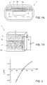
- As shown in the schematic sections in
Figures 1a and 1b , a linear oxygen sensor, of a single-cell type, indicated in general by 1, comprises: - an
electrolytic layer 2, including, for example zirconium dioxide, ZrO2; - a first and a
second electrode electrolyte layer 2, set on opposite sides in relation to thesame electrolyte layer 2, and defining a first (positive pole) and, respectively, a second (negative pole) electrical terminal of thelinear oxygen sensor 1; - a
diffusion layer 4, above thefirst electrode 3a and in contact, during operation, with the gases whose oxygen concentration is desired to be measured, for example discharge gases (thesecond electrode 3b being placed in contact with an environment containing a reference air). - The
linear oxygen sensor 1 furthermore comprises: areference air duct 5, defining the aforesaid environment in contact with thesecond electrode 3b; and aheating element 6, set below thereference air duct 5, and suitably driven by applying an electrical quantity, to bring the electrolytic sensing cell to a suitable temperature (for example equal to 700°). - During operation, the cell current Ip that flows between the electrical terminals of the linear oxygen sensor 1 (denoted schematically with a
current generator 7 inFigure 1b ), across which a biasing voltage ΔV of a suitable value is set (Figure 1b shows a voltage generator ΔV in series with a resistor 8), is indicative of the oxygen percentage; this cell current Ip is consequently indicative of the air/fuel ratio A/F, as illustrated by way of example inFigure 2 . - It is known that, in the field of controlling linear oxygen sensors, the applied electrical quantities (in particular, the biasing voltage between the associated electrical terminals) are required to be within given (upper and lower) thresholds; exceeding (above or below) these thresholds may in fact cause the so-called phenomenon of "blackening" of the electrolyte, which is potentially damaging to the sensor or, in any case, sufficient to compromise its proper operation.
- Furthermore, in the case of the previously illustrated single-cell
linear oxygen sensor 1, the voltage applied between the corresponding electrical terminals is required to have a given relationship with the cell current Ip, with a suitable variation in correspondence with the variation of the same cell current Ip. - The aim of the present invention is to provide a solution for controlling a single-cell linear oxygen sensor, with a simple and inexpensive configuration, which offers good electrical performance.
- According to the present invention, a control circuit for controlling a linear oxygen sensor, and a corresponding control method, are therefore provided, as defined in the accompanying claims.
- For a better understanding of the present invention, a preferred embodiment will now be described, by way of example, which is not limiting, with reference to the accompanying Figures, wherein:
-
Figures 1a-1b are schematic section diagrams, with different levels of detail, of a known type of single-cell linear oxygen sensor; -
Figure 2 is a plot relating to electrical and oxygen concentration quantities in the sensor ofFigures 1a, 1b ; -
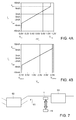
Figure 3 is a block diagram of a control circuit for a linear oxygen sensor, according to one embodiment of the present solution; -
Figures 4a, 4b are plots of electrical quantities relating to the control circuit inFigure 3 ; -
Figure 5 is a more detailed circuit diagram of the control circuit inFigure 3 ; -
Figure 6 is a flow diagram of control operations performed by the control circuit ofFigure 3 ; and -
Figure 7 schematically shows a portion of an internal combustion engine in which the linear oxygen sensor and the corresponding control circuit can be employed. - As shown in
Figure 3 , one aspect of the present solution envisages implementing a control circuit, purely analog in this embodiment, indicated as a whole by 10, for the biasing of a single-cell linear oxygen sensor, again denoted by 1. - The
linear oxygen sensor 1 may be structured in a similar way to what was previously discussed, with reference toFigures 1a-1b , and is schematised, from the circuit point of view, with thecurrent generator 7, which is connected between the first and second electrical terminals, denoted here with 11a and 11b; and the series connection ofresistor 8 andcapacitor 9 that are connected between the same first and secondelectrical terminals - In particular, the
control circuit 10 is configured to generate a suitable biasing voltage, indicated here with ΔVs, between theelectrical terminals linear oxygen sensor 1, as a function of the value of the cell current Ip supplied by the samelinear oxygen sensor 1 based on the detected oxygen concentration, respecting the pattern and minimum and maximum thresholds envisaged by design, for the proper operation of the samelinear oxygen sensor 1. - During operation, a first voltage Vs + is present on the first
electrical terminal 11a of thelinear oxygen sensor 1, which is assumed for example to be positive, while a second voltage Vs - is present on the secondelectrical terminal 11b of the linear oxygen sensor 1 (for example, this is also positive, and lower compared to the first voltage Vs +); the biasing voltage ΔV s is given by the difference between the first and second voltages Vs + ' Vs - : ΔVs=Vs + - Vs -. - In detail, the
control circuit 10 comprises: - a
sensing stage 12, coupled to thesecond terminal 11b of thelinear oxygen sensor 1, configured to supply a sense voltage Vsense, indicative of the value of the cell current Ip, referred to a reference voltage Vref, having a suitable value, for example equal to 3.8 V; in particular, the sense voltage Vsense increases or decreases (according to the direction of the cell current Ip) proportionally to the same cell current Ip; - a
buffer stage 13, having the function of impedance decoupling, connected to the output of thesensing stage 12; - an
amplifier stage 14, coupled to the output of thesensing stage 12 by thebuffer stage 13, configured to process the sense voltage Vsense, by applying a suitable gain k and offset voltage Vsum as subsequently described in greater detail, generating a processed voltage Vout; - an
adder stage 16, which receives the second voltage Vs - on the secondelectrical terminal 11b of thelinear oxygen sensor 1, at a first input, and the processed voltage Vout, at a second input, and performs a weighted sum thereof to compensate the gain k previously applied by theamplifier stage 14, thus generating the first voltage Vs + to be applied to the firstelectrical terminal 11a of the samelinear oxygen sensor 1; - a selective-
coupling stage 18, set between the output of theadder stage 16 and the firstelectrical terminal 11a, and configured to selectively couple the output of theadder stage 16 to the same firstelectrical terminal 11a, according to a control signal Sc; in particular, in correspondence with a first value of the control signal Sc (for example high), the first voltage Vs + generated by theadder stage 16 is supplied to the firstelectrical terminal 11a of thelinear oxygen sensor 1, while for a second value of the same control signal Sc (for example low), the output of theadder stage 16 is brought to a high-impedance state, decoupled from the same firstelectrical terminal 11a. - Together, the
sensing stage 12 and theamplifier stage 14 form a transresistance block, indicated as a whole with 17, designed to generate, as a function of the cell current Ip, a suitable value of the processed voltage Vout (which determines the appropriate value of the first voltage Vs + on thefirst terminal 11a of thelinear oxygen sensor 1, in relation to thesecond terminal 11b). - In particular, as shown in
Figure 4a , the electrolytic sensing cell of thelinear oxygen sensor 1 has a desired pattern, according to design, which links ("maps") the variation of the cell current Ip to the biasing voltage ΔV s applied between theterminals - In the shown example, as the cell current Ip varies, this pattern for the biasing voltage ΔVs envisages: a minimum voltage limit Vmin, in the example, close to 0 V, for values of the cell current Ip below a lower threshold Ipmin; a maximum voltage limit Vmax, in the example, close to 1.2 V, for values of the cell current Ip above an upper threshold Ipmax; and, between the minimum and maximum voltage limits Vmin, Vmax, a linear ramp pattern, with a preset slope. Furthermore, for a null value of the cell current Ip a non-null value of the biasing voltage ΔV s is envisaged, in the example equal to about 0.4 V.
- According to one aspect of the present solution, the gain k and the offset voltage Vsum of the
amplifier stage 14 are suitably selected to replicate the aforesaid desired (by design) pattern of the biasing voltage ΔV s , as the cell current Ip varies. - In particular, for values of the cell current Ip below the lower threshold Ipmin, or above the upper threshold Ipmax, the gain k is such that the
amplifier stage 14 operates at the upper or lower saturation voltages (so-called "supply rails"); in other words, theamplifier stage 14 operates across all of its dynamics, with the processed voltage Vout that cannot exceed the upper and lower saturation voltages. - A possible pattern of the processed voltage Vout is illustrated in
Figure 4b : the value of the processed voltage Vout is comprised between the upper and lower saturation voltages, indicated here with Vsatinf, Vsatsup, and furthermore a non-null value of the same processed voltage Vout corresponds to a null value of the cell current Ip. - In this way, the
amplifier stage 14 ensures that the limits envisaged by design for the biasing voltage ΔVs applied to thelinear oxygen sensor 1 are respected. Furthermore, compensating the gain k applied by theamplifier stage 14, theadder stage 16 subsequently allows to obtain the desired value of the biasing voltage ΔVs, starting from the processed voltage Vout supplied by thesame amplifier stage 14. - According to a further aspect of the present solution, the
selective coupling stage 18 is operable to decouple thelinear oxygen sensor 1 from thecontrol circuit 10, in certain operating conditions, in particular when it is desired to measure the operating temperature of the samelinear oxygen sensor 1. - To measure this operating temperature, a measurement current Imeas is injected into the
linear oxygen sensor 1 and the corresponding resistance at the passage of the same measurement current Imeas is measured; the resistance measurement is indicative of the temperature of thelinear oxygen sensor 1. - In particular, to this end, a
measurement stage 19 is coupled to the first and secondelectrical terminals linear oxygen sensor 1, being configured to inject the measurement current Imeas, for example of an impulsive type, at the first and/or secondelectrical terminal electrical terminals - The
measurement stage 19 is configured, furthermore, to generate the control signal Sc for theselective coupling stage 18, suitably timed to perform the operation of temperature measurement. In particular, theselective coupling stage 18 is operated to decouple thelinear oxygen sensor 1 from thecontrol circuit 10, for a brief period of time, which is sufficient to measure the temperature, but is such as not to cause unwanted variations in the biasing conditions of the samelinear oxygen sensor 1, as determined by thecontrol circuit 10. - A possible embodiment of the
control circuit 10 will now be described in further detail, with reference toFigure 5 . - The
sensing stage 12 comprises in this case: asensing resistor 20, having resistance Rsense, connected between the secondelectrical terminal 11b of thelinear oxygen sensor 1 and a first internal node N1; and afirst buffer amplifier 21, which has a non-inverting input that receives the reference voltage Vref, an inverting input connected to the output (in voltage-follower configuration), and the output connected to the first internal node N1, on which it thus feeds-back the same reference voltage Vref. - During operation, the cell current Ip determines a drop in voltage on the
sensing resistor 20 equal to Rsense · Ip, so the sense voltage Vsense is equal to:
- The
buffer stage 13 comprises a second buffer amplifier 23, which has a non-inverting input connected to the secondelectrical terminal 11b of thelinear oxygen sensor 1, an inverting input connected to the output (in voltage follower configuration), and the output connected to a second internal node N2, on which it thus feeds-back the second voltage
- The
amplifier stage 14 comprises anoperational amplifier 24, having: a non-inverting input, connected to the second internal node N2 via afirst gain resistor 25, having resistance R1, and also connected to a reference ground terminal GND via asecond gain resistor 26, having resistance R2; an inverting input, connected via athird gain resistor 27, in the example having resistance R1, to an offset input, on which the offset voltage Vsum is present, and also connected to the corresponding output via afourth gain resistor 28, having resistance R2; and the output providing the processed voltage Vout. - In a non-illustrated manner, the offset voltage Vsum can be generated from the same reference voltage Vref, for example by a resistive divider.
- The processed voltage Vout is thus given by the following expression:

- The
operational amplifier 24 furthermore receives a supply voltage VDDS, for example equal to 5 V, whose value determines, in a known manner, the values of the corresponding upper and lower saturation voltages (supply rails) Vsatinf, Vsatsup. - The
adder stage 16 comprises, in turn, anoperational amplifier 30, having: a non-inverting input, connected to the second internal node N2 via afifth gain resistor 31, having resistance R1, and also connected to the output of theoperational amplifier 24 of theamplifier stage 14 via asixth gain resistor 32, having resistance R2; an inverting input, connected via aseventh gain resistor 33, in the example, having resistance R2 to the ground terminal GND, and furthermore connected to a third internal node N3 via aneighth gain resistor 34, having resistance R1; and an output connected to the third internal node N3 via afurther resistor 35, for the purpose of protection in the case of short-circuit, and providing the first voltage Vs +, for thefirst terminal 11a of thelinear oxygen sensor 1. - The non-inverting input of the
operational amplifier 30 is also connected to the ground terminal GND via a condenser 35', having "loop-compensation" functions to stabilise the control loop. - The first voltage Vs + is thus given by the following expression:

- The
selective coupling stage 18 comprises: a first and asecond switch element electrical terminal 11a of thelinear oxygen sensor 1, and having control terminals connected to each other and to a fourth internal node N4. The same fourth internal node N4 is connected to the third internal node N3 via afurther resistor 37. - The
selective coupling stage 18 further comprises abipolar transistor 38, having a base terminal connected to a control input where it receives (from the measurement stage 19) the control signal Sc through aresistor 39, a collector terminal connected to the fourth internal node N4 via aresistor 40, and an emitter terminal connected to the ground terminal GND. - In the illustrated embodiment, the
aforesaid measuring stage 19 comprises: a first, bidirectionalcurrent generator 41, connected to the firstelectrical terminal 11a of thelinear oxygen sensor 1, receiving a supply voltage VBAT (that also supplies theoperational amplifiers 21, 23 and 30); and a second, bidirectionalcurrent generator 42, connected to the secondelectrical terminal 11b of the samelinear oxygen sensor 1, receiving the supply voltage VBAT. - The first and second
current generator electrical terminal linear oxygen sensor 1, said current being provided by a pair of consecutive impulses, with opposite polarity and a duration, for example, equal to 0 µs and an amplitude equal to +/-2.5 mA. - The measurement current Imeas can be supplied alternatively in both directions, towards the respective
electrical terminal electrical terminal - As indicated previously, the duration of the temperature measuring operation is such that it does not alter the biasing conditions and therefore the state of the electrolyte in the
electrolyte layer 2 of thelinear oxygen sensor 1. - The measuring
stage 19 furthermore comprises acontrol unit 44, configured to drive the first and secondcurrent generator selective coupling stage 18, based on a same timing signal. In a manner not shown, thecontrol unit 44 can also be operatively coupled to a high-level management unit, for example of the engine in which thelinear oxygen sensor 1 is employed, from which it may receive suitable commands. - During operation, the
control unit 44 is able to start the procedure for measuring the temperature of thelinear oxygen sensor 1 by switching the control signal Sc; subsequently, thesame control unit 44 drives thecurrent generators linear oxygen sensor 1, determining the temperature value based on the resistance measurement between theelectrical terminals linear oxygen sensor 1. - In greater detail, and as illustrated in
Figure 6 , the temperature measurement procedure implemented by thecontrol unit 44 of the measuringstage 19, envisages, in afirst step 50, switching of the first andsecond switch element selective coupling stage 18 to decouple thecontrol circuit 10 from the linear oxygen sensor 1 (in particular, both of theswitches linear oxygen sensor 1. - Subsequently, at
step 51, thecontrol unit 44 determines supply of the measurement current Imeas through thelinear oxygen sensor 1, driving the first and/or secondcurrent generator - The resistance of the
linear oxygen sensor 1 is then measured,step 52, as a function of the drop in voltage between the correspondingelectrical terminals - In this way, the
control unit 44 determines the temperature value, as a function of the measured resistance, atstep 54. - In a
subsequent step 55, thecontrol unit 44 may verify whether the previously determined temperature value T corresponds, or not, to a desired operating temperature Tdes for thelinear oxygen sensor 1. - If verification is positive, no correction is made, and the
control circuit 10 can subsequently be coupled again to thelinear oxygen sensor 1, to supply the biasing voltage ΔV s and continue the oxygen concentration sensing operations,step 56. - Otherwise,
step 57, the drive current supplied to theheating element 6 of thelinear oxygen sensor 1 can be suitably modified (seeFigure 1a ), according to the difference between the temperature T and the desired operating temperature Tdes. - It is possible to return from
step 57 to step 51, in a iterative manner, for another check of the value of the temperature T, until the same temperature T reaches the desired value. - In particular, measurement of the temperature T of the
linear oxygen sensor 1, and any correction of the drive quantities supplied to theheating element 6, can be carried out on a continuous basis, at fixed periodic intervals, or whenever required, in other words when it is suitable to monitor and update the value of the same temperature. - In a manner that is non-illustrated, but which is evident from the discussion, return from
step 56 to step 50 (for a new measurement of the temperature T) occurs for example after a set waiting time, or after receiving from the high level management unit coupled to the control unit 44 a command to monitor the temperature. - The advantages of the proposed solution appear evident from the previous description.
- In any case, it is again underlined that it allows effective biasing and effective control of a single-cell linear oxygen sensor, but with reduced circuit complexity and implementation costs.
- The safety of the
control circuit 10 is intrinsically guaranteed, since it is impossible for the biasing voltage to assume values, which are higher or lower than the limit values tolerable by the linear oxygen sensor 1 (in particular, thanks to the limited dynamics of theoperational amplifier 24 of the processing stage 14). - The possibility of decoupling the control circuit of the
linear oxygen sensor 1, when the relative operating temperature needs to be measured is particularly advantageous. - Advantageously, the
control circuit 10, in the described embodiment being of a completely analog type, is able to cooperate with additional processing units (for example microprocessor units), which can be operatively coupled to the samelinear oxygen sensor 1, for example to perform operations of reading and processing the data acquired and/or operations of diagnosing the operation of the samelinear oxygen sensor 1. These processing units may be coupled to the same printed circuit board (PCB) in which the control circuit is formed 10. - As shown schematically in
Figure 7 , the described solution may advantageously be applied, for example in aninternal combustion engine 60, to control alinear oxygen sensor 1, set inside adischarge conduit 61, for measuring the concentration of oxygen in discharge gases, and thus provide an indication of the A/F ratio. - In the illustrated example, the
linear oxygen sensor 1 is, for example positioned before acatalyst 63, suitable for eliminating polluting substances present in the combustion gases, before the same gases are released into the environment; however, in a non-illustrated manner, thelinear oxygen sensor 1 could equally be positioned downstream of the catalyst 63 (or positioned at an intake conduit of the internal combustion engine 60). - Finally, it is clear that modifications and variations can be made to what is described and illustrated here without departing from the scope of the present invention, as defined in the accompanying claims.
- In particular, it is evident that the
control circuit 10 may implement different curves that describe the desired pattern (according to design), which links the variation of the cell current Ip to the biasing voltage ΔV s between theelectrical terminals linear oxygen sensor 1, for example in terms of a different slope of the linear ramp pattern, and/or a different minimum voltage limit Vmin, and/or a different maximum voltage limit Vmax. - Furthermore, it is again underlined that the
control circuit 10 may be employed for controlling single-cell linear oxygen sensors in various applications, also in ones different from the previously-referenced internal combustion engine.
Claims (19)
- A control circuit (10) for a single-cell linear oxygen sensor (1) having a first (11a) and a second (11b) electrical terminals on which a first voltage (Vs +) and, respectively, a second voltage (Vs -) are designed to be provided, wherein a cell current (Ip) between said first (11a) and second (11b) electrical terminals is indicative of a detected oxygen concentration, said control circuit (10) being configured to generate a biasing voltage (ΔV s ) between said first (11a) and second (11b) electrical terminals, having a preset pattern as a function of said cell current (Ip),
characterized by comprising:a transresistance block (17), coupled to said second electrical terminal (11b) and configured to generate a processed voltage (Vout) as a function of said cell current (Ip) and of said preset pattern; andan adder stage (16), coupled to said transresistance block (17) and to said second electrical terminal (11b), and configured to perform a sum between said processed voltage (Vout) and said second voltage (Vs -), to generate said first voltage (Vs +) for the first electrical terminal (11a) of said linear oxygen sensor (1), so that said biasing voltage (ΔV s ) has the preset pattern as a function of the cell current (Ip). - The circuit according to claim 1, wherein said transresistance block (17) comprises:a current sensing stage (12), coupled to said second terminal (11b) and configured to generate a sense voltage (Vsense) as a function of said cell current (Ip); anda processing stage (14), coupled to said current sensing stage (12) and configured to process said sense voltage (Vsense) based on said preset pattern to generate said processed voltage (Vout).
- The circuit according to claim 2, wherein, as the cell current (Ip) varies, said preset pattern envisages:a minimum voltage limit (Vmin), for cell current (Ip) values below a lower threshold (Ipmin);a maximum voltage limit (Vmax), for cell current (Ip) values above an upper threshold (Ipmax); andbetween the minimum (Vmin) and maximum (Vmax) voltage limits, a linear ramp pattern, with a preset slope.
- The circuit according to claim 3, wherein said processing stage (14) comprises an operational amplifier (24) having an upper saturation voltage (Vsatsup) and a lower saturation voltage (Vsatinf) depending on a related supply voltage (VDDS) ; wherein said operational amplifier (24) has a gain (k), which is such that the processed voltage (Vout) is equal to the upper saturation voltage (Vsatsup) for values of the cell current (Ip) above said upper threshold (Ipmax), and equal to the lower saturation voltage (Vsatinf) for values of the cell current (Ip) below said lower threshold (Ipmin).
- The circuit according to claim 4, wherein said operational amplifier (24) has an offset voltage (Vsum), with a value dependent on said preset pattern.
- The circuit according to claim 4 or 5, wherein said adder stage (16) is configured to compensate the gain (k) applied by said processing stage (14) to said processed voltage (Vout), in the sum between said processed voltage (Vout) and said second voltage (Vs -) on the second electrical terminal (11b) of the linear oxygen sensor (1).
- The circuit according to any one of the preceding claims, wherein said current sensing stage (12) comprises a sensing resistor (20), connected between said second electrical terminal (11b) of said linear oxygen sensor (1) and a node (N1) set at a reference voltage (Vref).
- The circuit according to any one of the preceding claims, further comprising a decoupling stage (18), connected between a sum output (N3) of said adder stage (16) and said first electrical terminal (11a) of said linear oxygen sensor (1); said decoupling stage (18) being designed to receive a control signal (Sc), and operable based on said control signal (Sc) for selectively decoupling said sum output (N3) from said first electrical terminal (11a), during at least one operating condition.
- The circuit according to claim 8, wherein said operating condition is a measurement condition for measuring an operating temperature (T) of said linear oxygen sensor (1), envisaging: sending a measurement current (Imeas) between said first (11a) and second (11b) electrical terminals of said linear oxygen sensor (1); and measuring the resistance of said linear oxygen sensor (1) at the passage of said measurement current (Imeas) ; wherein said decoupling stage (18) is configured to decouple said sum output (N3) from said first electrical terminal (11a) in a manner temporally limited to performing of said operating temperature measurement.
- The circuit according to claim 8 or 9, wherein said decoupling stage (18) comprises at least one switch element (36a, 36b), operable by said control signal (Sc) to bring the sum output (N3) of said adder stage (16) to a high-impedance state.
- The circuit according to any one of the claims 8-10, comprising a measuring stage (19), coupled to said first (11a) and second (11b) electrical terminals of said linear oxygen sensor (1) and configured to: generate said control signal (Sc); provide said measurement current (Imeas) between said first (11a) and second (11b) electrical terminals of said linear oxygen sensor (1); and measure the resistance of said linear oxygen sensor (1) at the passage of said measurement current (Imeas).
- The circuit according to any one of the preceding claims, of a purely analog type.
- An internal combustion engine (60), comprising a discharge and/or intake conduit (61), and a linear oxygen sensor (1) according to any of the previous claims, configured to measure an oxygen concentration in the gases present in said discharge and/or intake conduit (61).
- A control method for a single-cell linear oxygen sensor (1) having a first (11a) and a second (11b) electrical terminals on which a first voltage (Vs +) and, respectively, a second voltage (Vs -) are designed to be provided, wherein a cell current (Ip) between said first (11a) and second (11b) electrical terminals is indicative of a detected oxygen concentration, comprising the step of generating a biasing voltage (ΔV s ) between said first (11a) and second (11b) electrical terminals, having a preset pattern as a function of said cell current (Ip),
characterized in that the step of generating comprises:generating a processed voltage (Vout) as a function of said cell current (Ip) and of said preset pattern; andperforming a sum between said processed voltage (Vout) and said second voltage (Vs -), to generate said first voltage (Vs +) for the first electrical terminal (11a) of said linear oxygen sensor (1), so that said biasing voltage (ΔV s ) has the preset pattern as a function of the cell current (Ip). - The method according to claim 14, wherein said step of generating comprises:generating a sense voltage (Vsense) as a function of said cell current (Ip); andprocessing said sense voltage (Vsense) based on said preset pattern for generating said processed voltage (Vout).
- The method according to claim 14 or 15, wherein said step of generating is implemented by a control circuit (10) coupled to the linear oxygen sensor (1); further comprising: selectively decoupling said first electrical terminal (11a) from said control circuit (10) during at least one operating condition, wherein said operating condition is a measurement condition for measuring an operating temperature (T) of said linear oxygen sensor (1), envisaging: sending a measurement current (Imeas) between said first (11a) and second (11b) electrical terminals of said linear oxygen sensor (1); and measuring the resistance of said linear oxygen sensor (1) at the passage of said measurement current (Imeas); wherein said step of decoupling has a duration temporally limited to performing said measurement of the operating temperature.
- The method according to claim 16, further comprising, following said decoupling step: sending said measurement current (Imeas) between said first (11a) and second (11b) electrical terminals of said linear oxygen sensor (1) ; measuring the resistance of said linear oxygen sensor (1) at the passage of said measurement current (Imeas) to determine said operating temperature (T) as a function of the measured resistance; and coupling again said first electrical terminal (11a) to said control circuit (10) at the end of said operating temperature measurement.
- The method according to claim 17, wherein a heating element (6) is coupled to the linear oxygen sensor (1); further comprising, in the case where the measurement of the operating temperature (T) is different from a preset value (Tdes) the step of varying a driving condition of said heating element (6), before said step of coupling again said first electrical terminal (11a) to the control circuit (10).
- The method according to claim 17 or 18, wherein said step of coupling again said first electrical terminal (11a) to the control circuit (10) is performed when the operating temperature (T) has a desired relationship with a preset value (Tdes).
Applications Claiming Priority (1)
| Application Number | Priority Date | Filing Date | Title |
|---|---|---|---|
| ITUB2015A003146A ITUB20153146A1 (en) | 2015-08-17 | 2015-08-17 | CIRCUIT AND METHOD OF CONTROL OF A SINGLE CELL LINEAR OXYGEN SENSOR |
Publications (2)
| Publication Number | Publication Date |
|---|---|
| EP3133391A1 true EP3133391A1 (en) | 2017-02-22 |
| EP3133391B1 EP3133391B1 (en) | 2018-06-13 |
Family
ID=54705730
Family Applications (1)
| Application Number | Title | Priority Date | Filing Date |
|---|---|---|---|
| EP16184315.6A Active EP3133391B1 (en) | 2015-08-17 | 2016-08-16 | Circuit and method for controlling a single-cell linear oxygen sensor |
Country Status (5)
| Country | Link |
|---|---|
| US (1) | US10203299B2 (en) |
| EP (1) | EP3133391B1 (en) |
| CN (1) | CN106468683B (en) |
| BR (1) | BR102016018959B8 (en) |
| IT (1) | ITUB20153146A1 (en) |
Citations (2)
| Publication number | Priority date | Publication date | Assignee | Title |
|---|---|---|---|---|
| EP1001261A1 (en) | 1998-11-13 | 2000-05-17 | MAGNETI MARELLI S.p.A. | Control device for a linear oxygen sensor |
| US20070215470A1 (en) * | 2006-03-14 | 2007-09-20 | Denso Corporation | Gas concentration measuring apparatus designed to enhance response of sensor |
Family Cites Families (8)
| Publication number | Priority date | Publication date | Assignee | Title |
|---|---|---|---|---|
| US6382013B1 (en) * | 2000-05-12 | 2002-05-07 | Daimlerchrysler Corporation | Method of reading an oxygen sensor input |
| DE10244466C1 (en) * | 2002-09-24 | 2003-10-02 | Siemens Ag | Switching arrangement, for operating linear exhaust gas probe for vehicle engine, comprises first comparison switching, pump current source for preparing current and second switching circuit for comparing voltage on pump cell |
| JP2004340859A (en) * | 2003-05-19 | 2004-12-02 | Hitachi Unisia Automotive Ltd | Activation determination method for oxygen sensor |
| CN100462535C (en) * | 2004-09-17 | 2009-02-18 | 株式会社日立制作所 | Exhaust gas sensor activation judgment and air-fuel ratio control system/method |
| JP2009127595A (en) * | 2007-11-27 | 2009-06-11 | Toyota Motor Corp | Air-fuel ratio sensor abnormality diagnosis device |
| US7630840B2 (en) * | 2007-11-27 | 2009-12-08 | Gm Global Technology Operations, Inc. | Oxygen sensor readiness detection |
| DE102009050221A1 (en) * | 2009-10-22 | 2011-05-05 | Continental Automotive Gmbh | Device and method for the diagnosis of an exhaust gas sensor |
| CN103133165A (en) * | 2011-11-25 | 2013-06-05 | 上海汽车集团股份有限公司 | Method and system for judging engine failures based on linear exhaust gas oxygen sensor |
-
2015
- 2015-08-17 IT ITUB2015A003146A patent/ITUB20153146A1/en unknown
-
2016
- 2016-08-16 EP EP16184315.6A patent/EP3133391B1/en active Active
- 2016-08-16 US US15/238,068 patent/US10203299B2/en active Active
- 2016-08-17 CN CN201610683468.4A patent/CN106468683B/en active Active
- 2016-08-17 BR BR102016018959A patent/BR102016018959B8/en active IP Right Grant
Patent Citations (2)
| Publication number | Priority date | Publication date | Assignee | Title |
|---|---|---|---|---|
| EP1001261A1 (en) | 1998-11-13 | 2000-05-17 | MAGNETI MARELLI S.p.A. | Control device for a linear oxygen sensor |
| US20070215470A1 (en) * | 2006-03-14 | 2007-09-20 | Denso Corporation | Gas concentration measuring apparatus designed to enhance response of sensor |
Also Published As
| Publication number | Publication date |
|---|---|
| US20170052141A1 (en) | 2017-02-23 |
| BR102016018959A2 (en) | 2017-02-21 |
| BR102016018959B1 (en) | 2021-01-26 |
| BR102016018959B8 (en) | 2021-09-08 |
| CN106468683B (en) | 2020-02-11 |
| US10203299B2 (en) | 2019-02-12 |
| ITUB20153146A1 (en) | 2017-02-17 |
| EP3133391B1 (en) | 2018-06-13 |
| CN106468683A (en) | 2017-03-01 |
Similar Documents
| Publication | Publication Date | Title |
|---|---|---|
| KR101734946B1 (en) | Device and method for diagnosing an exhaust gas sensor | |
| US9625400B2 (en) | Method for setting a temperature of a sensor element | |
| EP1028244B1 (en) | Method of controlling and diagnosing the heater of an engine exhaust gas composition sensor | |
| US8632667B2 (en) | Deterioration signal generation device for oxygen sensor | |
| JP6048442B2 (en) | Device impedance detector for oxygen concentration sensor | |
| US9518954B2 (en) | Gas sensor control device | |
| US6467954B2 (en) | Resistance component detecting apparatus for an oxygen concentration sensor and oxygen-concentration detecting apparatus | |
| CN108896641B (en) | Sensor device and sensor unit | |
| US10669963B2 (en) | Anomaly determination apparatus and control system | |
| CN101976086A (en) | Oxygen sensor heating control method and heating control circuit adopting same | |
| CN112526066B (en) | Gas concentration measuring device and method | |
| EP2551666A1 (en) | Oxygen content sensor input device | |
| US6409969B1 (en) | System and method for controlling a self-heated gas sensor based on sensor impedance | |
| US11467125B2 (en) | Sensor control device | |
| CN100401054C (en) | monitor and monitoring method of gas sensor | |
| EP3133391B1 (en) | Circuit and method for controlling a single-cell linear oxygen sensor | |
| JP6700910B2 (en) | Gas sensor controller | |
| JP4045148B2 (en) | Simulator for simulating operation of NOx sensor and oxygen sensor | |
| JPH10153576A (en) | Air-fuel ratio sensor | |
| US9714928B2 (en) | Gas-sensor control device | |
| JP6032246B2 (en) | Control circuit | |
| US10830729B2 (en) | Sensor control device and gas detection system | |
| JPH03272452A (en) | Diagnosis of abnormality of air/fuel ratio sensor | |
| JP4016964B2 (en) | Gas concentration detector | |
| JP3633371B2 (en) | Air-fuel ratio detection device |
Legal Events
| Date | Code | Title | Description |
|---|---|---|---|
| PUAI | Public reference made under article 153(3) epc to a published international application that has entered the european phase |
Free format text: ORIGINAL CODE: 0009012 |
|
| AK | Designated contracting states |
Kind code of ref document: A1 Designated state(s): AL AT BE BG CH CY CZ DE DK EE ES FI FR GB GR HR HU IE IS IT LI LT LU LV MC MK MT NL NO PL PT RO RS SE SI SK SM TR |
|
| AX | Request for extension of the european patent |
Extension state: BA ME |
|
| 17P | Request for examination filed |
Effective date: 20170821 |
|
| GRAP | Despatch of communication of intention to grant a patent |
Free format text: ORIGINAL CODE: EPIDOSNIGR1 |
|
| INTG | Intention to grant announced |
Effective date: 20171207 |
|
| GRAJ | Information related to disapproval of communication of intention to grant by the applicant or resumption of examination proceedings by the epo deleted |
Free format text: ORIGINAL CODE: EPIDOSDIGR1 |
|
| GRAR | Information related to intention to grant a patent recorded |
Free format text: ORIGINAL CODE: EPIDOSNIGR71 |
|
| GRAS | Grant fee paid |
Free format text: ORIGINAL CODE: EPIDOSNIGR3 |
|
| GRAA | (expected) grant |
Free format text: ORIGINAL CODE: 0009210 |
|
| INTC | Intention to grant announced (deleted) | ||
| AK | Designated contracting states |
Kind code of ref document: B1 Designated state(s): AL AT BE BG CH CY CZ DE DK EE ES FI FR GB GR HR HU IE IS IT LI LT LU LV MC MK MT NL NO PL PT RO RS SE SI SK SM TR |
|
| INTG | Intention to grant announced |
Effective date: 20180504 |
|
| REG | Reference to a national code |
Ref country code: GB Ref legal event code: FG4D |
|
| REG | Reference to a national code |
Ref country code: CH Ref legal event code: EP Ref country code: AT Ref legal event code: REF Ref document number: 1009006 Country of ref document: AT Kind code of ref document: T Effective date: 20180615 |
|
| REG | Reference to a national code |
Ref country code: IE Ref legal event code: FG4D |
|
| REG | Reference to a national code |
Ref country code: DE Ref legal event code: R096 Ref document number: 602016003528 Country of ref document: DE |
|
| REG | Reference to a national code |
Ref country code: FR Ref legal event code: PLFP Year of fee payment: 3 |
|
| REG | Reference to a national code |
Ref country code: NL Ref legal event code: MP Effective date: 20180613 |
|
| REG | Reference to a national code |
Ref country code: LT Ref legal event code: MG4D |
|
| PG25 | Lapsed in a contracting state [announced via postgrant information from national office to epo] |
Ref country code: SE Free format text: LAPSE BECAUSE OF FAILURE TO SUBMIT A TRANSLATION OF THE DESCRIPTION OR TO PAY THE FEE WITHIN THE PRESCRIBED TIME-LIMIT Effective date: 20180613 Ref country code: ES Free format text: LAPSE BECAUSE OF FAILURE TO SUBMIT A TRANSLATION OF THE DESCRIPTION OR TO PAY THE FEE WITHIN THE PRESCRIBED TIME-LIMIT Effective date: 20180613 Ref country code: CY Free format text: LAPSE BECAUSE OF FAILURE TO SUBMIT A TRANSLATION OF THE DESCRIPTION OR TO PAY THE FEE WITHIN THE PRESCRIBED TIME-LIMIT Effective date: 20180613 Ref country code: BG Free format text: LAPSE BECAUSE OF FAILURE TO SUBMIT A TRANSLATION OF THE DESCRIPTION OR TO PAY THE FEE WITHIN THE PRESCRIBED TIME-LIMIT Effective date: 20180913 Ref country code: FI Free format text: LAPSE BECAUSE OF FAILURE TO SUBMIT A TRANSLATION OF THE DESCRIPTION OR TO PAY THE FEE WITHIN THE PRESCRIBED TIME-LIMIT Effective date: 20180613 Ref country code: LT Free format text: LAPSE BECAUSE OF FAILURE TO SUBMIT A TRANSLATION OF THE DESCRIPTION OR TO PAY THE FEE WITHIN THE PRESCRIBED TIME-LIMIT Effective date: 20180613 Ref country code: NO Free format text: LAPSE BECAUSE OF FAILURE TO SUBMIT A TRANSLATION OF THE DESCRIPTION OR TO PAY THE FEE WITHIN THE PRESCRIBED TIME-LIMIT Effective date: 20180913 |
|
| PG25 | Lapsed in a contracting state [announced via postgrant information from national office to epo] |
Ref country code: HR Free format text: LAPSE BECAUSE OF FAILURE TO SUBMIT A TRANSLATION OF THE DESCRIPTION OR TO PAY THE FEE WITHIN THE PRESCRIBED TIME-LIMIT Effective date: 20180613 Ref country code: GR Free format text: LAPSE BECAUSE OF FAILURE TO SUBMIT A TRANSLATION OF THE DESCRIPTION OR TO PAY THE FEE WITHIN THE PRESCRIBED TIME-LIMIT Effective date: 20180914 Ref country code: LV Free format text: LAPSE BECAUSE OF FAILURE TO SUBMIT A TRANSLATION OF THE DESCRIPTION OR TO PAY THE FEE WITHIN THE PRESCRIBED TIME-LIMIT Effective date: 20180613 Ref country code: RS Free format text: LAPSE BECAUSE OF FAILURE TO SUBMIT A TRANSLATION OF THE DESCRIPTION OR TO PAY THE FEE WITHIN THE PRESCRIBED TIME-LIMIT Effective date: 20180613 |
|
| REG | Reference to a national code |
Ref country code: AT Ref legal event code: MK05 Ref document number: 1009006 Country of ref document: AT Kind code of ref document: T Effective date: 20180613 |
|
| PG25 | Lapsed in a contracting state [announced via postgrant information from national office to epo] |
Ref country code: NL Free format text: LAPSE BECAUSE OF FAILURE TO SUBMIT A TRANSLATION OF THE DESCRIPTION OR TO PAY THE FEE WITHIN THE PRESCRIBED TIME-LIMIT Effective date: 20180613 |
|
| PG25 | Lapsed in a contracting state [announced via postgrant information from national office to epo] |
Ref country code: CZ Free format text: LAPSE BECAUSE OF FAILURE TO SUBMIT A TRANSLATION OF THE DESCRIPTION OR TO PAY THE FEE WITHIN THE PRESCRIBED TIME-LIMIT Effective date: 20180613 Ref country code: RO Free format text: LAPSE BECAUSE OF FAILURE TO SUBMIT A TRANSLATION OF THE DESCRIPTION OR TO PAY THE FEE WITHIN THE PRESCRIBED TIME-LIMIT Effective date: 20180613 Ref country code: PL Free format text: LAPSE BECAUSE OF FAILURE TO SUBMIT A TRANSLATION OF THE DESCRIPTION OR TO PAY THE FEE WITHIN THE PRESCRIBED TIME-LIMIT Effective date: 20180613 Ref country code: EE Free format text: LAPSE BECAUSE OF FAILURE TO SUBMIT A TRANSLATION OF THE DESCRIPTION OR TO PAY THE FEE WITHIN THE PRESCRIBED TIME-LIMIT Effective date: 20180613 Ref country code: SK Free format text: LAPSE BECAUSE OF FAILURE TO SUBMIT A TRANSLATION OF THE DESCRIPTION OR TO PAY THE FEE WITHIN THE PRESCRIBED TIME-LIMIT Effective date: 20180613 Ref country code: AT Free format text: LAPSE BECAUSE OF FAILURE TO SUBMIT A TRANSLATION OF THE DESCRIPTION OR TO PAY THE FEE WITHIN THE PRESCRIBED TIME-LIMIT Effective date: 20180613 Ref country code: IS Free format text: LAPSE BECAUSE OF FAILURE TO SUBMIT A TRANSLATION OF THE DESCRIPTION OR TO PAY THE FEE WITHIN THE PRESCRIBED TIME-LIMIT Effective date: 20181013 |
|
| PG25 | Lapsed in a contracting state [announced via postgrant information from national office to epo] |
Ref country code: SM Free format text: LAPSE BECAUSE OF FAILURE TO SUBMIT A TRANSLATION OF THE DESCRIPTION OR TO PAY THE FEE WITHIN THE PRESCRIBED TIME-LIMIT Effective date: 20180613 |
|
| REG | Reference to a national code |
Ref country code: DE Ref legal event code: R097 Ref document number: 602016003528 Country of ref document: DE |
|
| PG25 | Lapsed in a contracting state [announced via postgrant information from national office to epo] |
Ref country code: MC Free format text: LAPSE BECAUSE OF FAILURE TO SUBMIT A TRANSLATION OF THE DESCRIPTION OR TO PAY THE FEE WITHIN THE PRESCRIBED TIME-LIMIT Effective date: 20180613 |
|
| PLBE | No opposition filed within time limit |
Free format text: ORIGINAL CODE: 0009261 |
|
| STAA | Information on the status of an ep patent application or granted ep patent |
Free format text: STATUS: NO OPPOSITION FILED WITHIN TIME LIMIT |
|
| PG25 | Lapsed in a contracting state [announced via postgrant information from national office to epo] |
Ref country code: LU Free format text: LAPSE BECAUSE OF NON-PAYMENT OF DUE FEES Effective date: 20180816 |
|
| REG | Reference to a national code |
Ref country code: BE Ref legal event code: MM Effective date: 20180831 |
|
| 26N | No opposition filed |
Effective date: 20190314 |
|
| REG | Reference to a national code |
Ref country code: IE Ref legal event code: MM4A |
|
| PG25 | Lapsed in a contracting state [announced via postgrant information from national office to epo] |
Ref country code: SI Free format text: LAPSE BECAUSE OF FAILURE TO SUBMIT A TRANSLATION OF THE DESCRIPTION OR TO PAY THE FEE WITHIN THE PRESCRIBED TIME-LIMIT Effective date: 20180613 Ref country code: DK Free format text: LAPSE BECAUSE OF FAILURE TO SUBMIT A TRANSLATION OF THE DESCRIPTION OR TO PAY THE FEE WITHIN THE PRESCRIBED TIME-LIMIT Effective date: 20180613 |
|
| PG25 | Lapsed in a contracting state [announced via postgrant information from national office to epo] |
Ref country code: IE Free format text: LAPSE BECAUSE OF NON-PAYMENT OF DUE FEES Effective date: 20180816 |
|
| PG25 | Lapsed in a contracting state [announced via postgrant information from national office to epo] |
Ref country code: BE Free format text: LAPSE BECAUSE OF NON-PAYMENT OF DUE FEES Effective date: 20180831 |
|
| PG25 | Lapsed in a contracting state [announced via postgrant information from national office to epo] |
Ref country code: AL Free format text: LAPSE BECAUSE OF FAILURE TO SUBMIT A TRANSLATION OF THE DESCRIPTION OR TO PAY THE FEE WITHIN THE PRESCRIBED TIME-LIMIT Effective date: 20180613 |
|
| PG25 | Lapsed in a contracting state [announced via postgrant information from national office to epo] |
Ref country code: MT Free format text: LAPSE BECAUSE OF NON-PAYMENT OF DUE FEES Effective date: 20180816 |
|
| PG25 | Lapsed in a contracting state [announced via postgrant information from national office to epo] |
Ref country code: TR Free format text: LAPSE BECAUSE OF FAILURE TO SUBMIT A TRANSLATION OF THE DESCRIPTION OR TO PAY THE FEE WITHIN THE PRESCRIBED TIME-LIMIT Effective date: 20180613 |
|
| PG25 | Lapsed in a contracting state [announced via postgrant information from national office to epo] |
Ref country code: CH Free format text: LAPSE BECAUSE OF NON-PAYMENT OF DUE FEES Effective date: 20190831 Ref country code: PT Free format text: LAPSE BECAUSE OF FAILURE TO SUBMIT A TRANSLATION OF THE DESCRIPTION OR TO PAY THE FEE WITHIN THE PRESCRIBED TIME-LIMIT Effective date: 20180613 Ref country code: LI Free format text: LAPSE BECAUSE OF NON-PAYMENT OF DUE FEES Effective date: 20190831 |
|
| PG25 | Lapsed in a contracting state [announced via postgrant information from national office to epo] |
Ref country code: MK Free format text: LAPSE BECAUSE OF NON-PAYMENT OF DUE FEES Effective date: 20180613 Ref country code: HU Free format text: LAPSE BECAUSE OF FAILURE TO SUBMIT A TRANSLATION OF THE DESCRIPTION OR TO PAY THE FEE WITHIN THE PRESCRIBED TIME-LIMIT; INVALID AB INITIO Effective date: 20160816 |
|
| GBPC | Gb: european patent ceased through non-payment of renewal fee |
Effective date: 20200816 |
|
| PG25 | Lapsed in a contracting state [announced via postgrant information from national office to epo] |
Ref country code: GB Free format text: LAPSE BECAUSE OF NON-PAYMENT OF DUE FEES Effective date: 20200816 |
|
| PGFP | Annual fee paid to national office [announced via postgrant information from national office to epo] |
Ref country code: DE Payment date: 20250724 Year of fee payment: 10 |
|
| PGFP | Annual fee paid to national office [announced via postgrant information from national office to epo] |
Ref country code: IT Payment date: 20250723 Year of fee payment: 10 |
|
| PGFP | Annual fee paid to national office [announced via postgrant information from national office to epo] |
Ref country code: FR Payment date: 20250725 Year of fee payment: 10 |