EP3133389A1 - Method and device for analyzing the composition of a grain-mog mixture - Google Patents
Method and device for analyzing the composition of a grain-mog mixture Download PDFInfo
- Publication number
- EP3133389A1 EP3133389A1 EP16184669.6A EP16184669A EP3133389A1 EP 3133389 A1 EP3133389 A1 EP 3133389A1 EP 16184669 A EP16184669 A EP 16184669A EP 3133389 A1 EP3133389 A1 EP 3133389A1
- Authority
- EP
- European Patent Office
- Prior art keywords
- grain
- thermal
- mog
- mog mixture
- mixture
- Prior art date
- Legal status (The legal status is an assumption and is not a legal conclusion. Google has not performed a legal analysis and makes no representation as to the accuracy of the status listed.)
- Granted
Links
- 239000000203 mixture Substances 0.000 title claims abstract description 201
- 238000000034 method Methods 0.000 title claims abstract description 73
- 230000005284 excitation Effects 0.000 claims abstract description 88
- 238000012545 processing Methods 0.000 claims abstract description 35
- 238000003384 imaging method Methods 0.000 claims abstract description 25
- 238000009826 distribution Methods 0.000 claims abstract description 22
- 238000001931 thermography Methods 0.000 claims description 48
- 238000012634 optical imaging Methods 0.000 claims description 20
- 241000251169 Alopias vulpinus Species 0.000 claims description 11
- 238000001816 cooling Methods 0.000 claims description 7
- 229910052736 halogen Inorganic materials 0.000 claims description 5
- 150000002367 halogens Chemical class 0.000 claims description 5
- 238000010438 heat treatment Methods 0.000 claims description 5
- 230000001939 inductive effect Effects 0.000 claims description 5
- 239000002699 waste material Substances 0.000 claims description 4
- 239000000463 material Substances 0.000 description 17
- 230000003287 optical effect Effects 0.000 description 13
- 230000005540 biological transmission Effects 0.000 description 4
- 238000000926 separation method Methods 0.000 description 4
- 210000005069 ears Anatomy 0.000 description 3
- 238000012546 transfer Methods 0.000 description 3
- 238000004140 cleaning Methods 0.000 description 2
- 238000005259 measurement Methods 0.000 description 2
- 238000012544 monitoring process Methods 0.000 description 2
- 238000002310 reflectometry Methods 0.000 description 2
- 238000007873 sieving Methods 0.000 description 2
- 238000003860 storage Methods 0.000 description 2
- 238000010792 warming Methods 0.000 description 2
- 241001124569 Lycaenidae Species 0.000 description 1
- 230000004913 activation Effects 0.000 description 1
- 238000002485 combustion reaction Methods 0.000 description 1
- 238000005520 cutting process Methods 0.000 description 1
- 238000001514 detection method Methods 0.000 description 1
- 230000000694 effects Effects 0.000 description 1
- 239000012634 fragment Substances 0.000 description 1
- 238000003306 harvesting Methods 0.000 description 1
- 239000010903 husk Substances 0.000 description 1
- 230000006698 induction Effects 0.000 description 1
- 239000002245 particle Substances 0.000 description 1
- 238000011144 upstream manufacturing Methods 0.000 description 1
Images


Classifications
-
- A—HUMAN NECESSITIES
- A01—AGRICULTURE; FORESTRY; ANIMAL HUSBANDRY; HUNTING; TRAPPING; FISHING
- A01D—HARVESTING; MOWING
- A01D41/00—Combines, i.e. harvesters or mowers combined with threshing devices
- A01D41/12—Details of combines
- A01D41/127—Control or measuring arrangements specially adapted for combines
-
- A—HUMAN NECESSITIES
- A01—AGRICULTURE; FORESTRY; ANIMAL HUSBANDRY; HUNTING; TRAPPING; FISHING
- A01D—HARVESTING; MOWING
- A01D41/00—Combines, i.e. harvesters or mowers combined with threshing devices
- A01D41/12—Details of combines
-
- A—HUMAN NECESSITIES
- A01—AGRICULTURE; FORESTRY; ANIMAL HUSBANDRY; HUNTING; TRAPPING; FISHING
- A01F—PROCESSING OF HARVESTED PRODUCE; HAY OR STRAW PRESSES; DEVICES FOR STORING AGRICULTURAL OR HORTICULTURAL PRODUCE
- A01F12/00—Parts or details of threshing apparatus
- A01F12/46—Mechanical grain conveyors
-
- A—HUMAN NECESSITIES
- A01—AGRICULTURE; FORESTRY; ANIMAL HUSBANDRY; HUNTING; TRAPPING; FISHING
- A01F—PROCESSING OF HARVESTED PRODUCE; HAY OR STRAW PRESSES; DEVICES FOR STORING AGRICULTURAL OR HORTICULTURAL PRODUCE
- A01F12/00—Parts or details of threshing apparatus
- A01F12/60—Grain tanks
-
- G—PHYSICS
- G01—MEASURING; TESTING
- G01J—MEASUREMENT OF INTENSITY, VELOCITY, SPECTRAL CONTENT, POLARISATION, PHASE OR PULSE CHARACTERISTICS OF INFRARED, VISIBLE OR ULTRAVIOLET LIGHT; COLORIMETRY; RADIATION PYROMETRY
- G01J5/00—Radiation pyrometry, e.g. infrared or optical thermometry
- G01J5/10—Radiation pyrometry, e.g. infrared or optical thermometry using electric radiation detectors
-
- G—PHYSICS
- G01—MEASURING; TESTING
- G01N—INVESTIGATING OR ANALYSING MATERIALS BY DETERMINING THEIR CHEMICAL OR PHYSICAL PROPERTIES
- G01N25/00—Investigating or analyzing materials by the use of thermal means
-
- G—PHYSICS
- G01—MEASURING; TESTING
- G01N—INVESTIGATING OR ANALYSING MATERIALS BY DETERMINING THEIR CHEMICAL OR PHYSICAL PROPERTIES
- G01N33/00—Investigating or analysing materials by specific methods not covered by groups G01N1/00 - G01N31/00
- G01N33/02—Food
- G01N33/10—Starch-containing substances, e.g. dough
-
- H—ELECTRICITY
- H04—ELECTRIC COMMUNICATION TECHNIQUE
- H04N—PICTORIAL COMMUNICATION, e.g. TELEVISION
- H04N23/00—Cameras or camera modules comprising electronic image sensors; Control thereof
- H04N23/20—Cameras or camera modules comprising electronic image sensors; Control thereof for generating image signals from infrared radiation only
- H04N23/23—Cameras or camera modules comprising electronic image sensors; Control thereof for generating image signals from infrared radiation only from thermal infrared radiation
-
- H—ELECTRICITY
- H04—ELECTRIC COMMUNICATION TECHNIQUE
- H04N—PICTORIAL COMMUNICATION, e.g. TELEVISION
- H04N5/00—Details of television systems
- H04N5/30—Transforming light or analogous information into electric information
- H04N5/33—Transforming infrared radiation
-
- G—PHYSICS
- G01—MEASURING; TESTING
- G01J—MEASUREMENT OF INTENSITY, VELOCITY, SPECTRAL CONTENT, POLARISATION, PHASE OR PULSE CHARACTERISTICS OF INFRARED, VISIBLE OR ULTRAVIOLET LIGHT; COLORIMETRY; RADIATION PYROMETRY
- G01J5/00—Radiation pyrometry, e.g. infrared or optical thermometry
- G01J2005/0077—Imaging
Definitions
- the invention pertains to a method for determining the composition of a grain-MOG mixture.
- the invention also pertains to a device for analyzing the composition of a grain-MOG mixture (1) comprising a kernel fraction and an MOG-fraction.
- MOG is widely used in the art to refer to "material other than grain”.
- Agricultural harvesters comprise a processing device that comprises a thresher.
- Harvested crop is introduced into the processing device in a raw form, in which stalks may still be present and the grain is still in the ears.
- the thresher separates grain kernels from other plant parts, such as stalks, ears, husks and the like.
- the threshed grain leaves the processing device to be transported to a storage facility, such as a grain tank.
- the separated MOG is discharged from the agricultural harvester.
- the processing device additionally comprises one or more sieves, to improve the separation between grain kernels and MOG, with the objective to transport a little chaff and other undesired material to the grain tank along with the threshed grain.
- US2009/0297040 discloses a method and device for crop particle discrimination. This device and method can be used to determine how much chaff is present in the grain-MOG mixture that travels from the processing device to the grain tank. If too much chaff is present, the processing device is likely in need of re-adjustment of some of the processing parameters.
- This object is achieved by a method for analyzing the composition of a grain-MOG mixture comprising a kernel fraction and an MOG-fraction, the method comprising the following steps:
- the grain-MOG mixture to be examined comprises kernels and other material.
- Other material in the grain-MOG mixture is for example chaff.
- Other plant materials such as parts of the ears and fragments of stalks or leaves may be present as well but in general the grain-MOG mixture will mainly be made up out of grain kernels and chaff.
- a special component that can be present in the grain-MOG mixture are "whitecaps".
- a “whitecap” is a piece of chaff in which a grain kernel is still present. So, in the threshing process the grain kernel is separated from the ear, but the separation between kernel and chaff did not take place.
- whitecaps cannot properly be detected. For example, with the method that is disclosed in US2009/0297040 , whitecaps will be seen as chaff, because of the reflectivity of the chaff piece that still surrounds the kernel of the whitecap.
- a sample volume of the grain-MOG mixture is analyzed in order to determine the share of kernels in the mixture.
- Kernels and materials other than grain e.g. chaff
- Kernels and materials other than grain e.g. chaff
- the temperature change of a kernel is different from the temperature change of e.g. a piece of chaff.
- a piece of chaff will heat up faster than a kernel.
- This principle is used to distinguish between kernels and material other than grain in the grain-MOG mixture.
- a sample volume of the grain-MOG mixture is subjected to a thermal excitation, e.g. the sample volume is heated or cooled. As e.g. heat will always penetrate into the grain-MOG mixture to some extent, it will be a volume of the grain-MOG mixture that is subjected to thermal excitation.
- the sample volume can be a part of the grain-MOG mixture or all of the grain-MOG mixture.
- the thermal excitation takes place at a thermal excitation location.
- the thermal excitation is carried out using a thermal excitator, which can be e.g. a heater, a cooler or a combined heater/cooler. Alternatively, other types of thermal excitation are used, e.g. induction or microwaves.
- the thermal excitator optionally comprises a thermal energy source, which is for example point-shaped, line-shaped or area-shaped.
- a thermal image is generated of at least a surface of the sample volume of the grain-MOG mixture that has been subjected to the thermal excitation.
- This thermal image is generated at an imaging location.
- the imaging location may be different from the thermal excitation location or the imaging location may be the same as the thermal excitation location.
- the temperature difference between the kernels and the material other than grain that result from the thermal excitation will be captured on the thermal image that is generated.
- a subsequent step in the method according to the invention is processing the thermal image and therewith obtaining data representing the temperature distribution over the thermal image.
- data relating to local temperature differences in the sample volume that is imaged becomes available.
- the temperature distribution in the sample volume of the grain-MOG mixture is related to the share of the kernel fraction in the grain-MOG mixture. This is for example done by obtaining the percentage of the total area of the thermal image that has a temperature that generally corresponds to the temperature that -given the amount of transferred thermal energy in the thermal excitation- can be expected for the kernels.
- the temperature distribution in the sample volume of the grain-MOG mixture is related to the share of the MOG- fraction in the grain-MOG mixture. This is for example done by obtaining the percentage of the total area of the thermal image that has a temperature that generally corresponds to the temperature that -given the amount of transferred thermal energy in the thermal excitation- can be expected for the kernels.
- the method according to the invention provides an elegant and efficient way of determining the share of kernels and/or MOG in a grain-MOG mixture.
- multiple subsequent thermal images are generated of at least a surface of the sample volume of the grain-MOG mixture that has been subjected to the thermal excitation. This allows taking the temperature profile of the kernel fraction and/or of the MOG-fraction in response to the thermal excitation into account when making the distinction between the kernels and the MOG. This increases the accuracy and the reliability of the analysis, as kernels and MOG show a different temperature profile in response to thermal excitation.
- the imaging location and the thermal excitation location coincide with each other. i.e. the imaging location is the same as the thermal excitation location.
- thermal excitation and thermal imaging take place simultaneously.
- the grain-MOG mixture is moved along a grain-MOG mixture path.
- the thermal excitation location and the imaging location are located along the grain-MOG mixture path. They can be at the same location or at different locations.
- the imaging location can be directly downstream of the thermal excitation location (seen in the direction of transport of the grain-MOG mixture along the grain-MOG mixture path) or the thermal excitation location and the imaging location can be spaced apart from each other.
- the thermal excitation is carried out in a modulated way, in the form of a pulse, in the form of a square pulse, in the form of a sinusoidal wave, or in the form of a step.
- the thermal image is obtained by continuous measurements e.g. by scanning along a line, e.g. in a transverse direction over the grain-MOG mixture path in embodiments in which the grain-MOG mixture is moved along a grain-MOG mixture path, or by taking a thermal image of an area of the grain-MOG mixture.
- multiple thermal images are taken, e.g. in a intermittent way.
- the scanning along a line in a transverse direction over the grain-MOG mixture path can alternatively optionally be carried out in an intermittent way.
- an ambient temperature is present in the vicinity of the grain-MOG mixture, and the thermal excitation results in the sample volume obtaining a surface temperature that is different from the ambient temperature.
- the surface temperature of the sample volume changes or is allowed to change towards the ambient temperature during the time between the thermal excitation and the generation of the thermal image, e.g. during the transfer from the thermal excitation location to the imaging location.
- the sample volume is heated up during the thermal excitation, and then allowed to cool somewhat before the thermal image is generated. Due to their mutual difference in heat capacity the kernels and the material other than grain do not only heat up at a mutually different rate, but they also cool down at a mutually different rate. Depending on the exact curves for the temperature changes over time given a certain heat input and difference with ambient temperature, it is possible that at a certain point in time the difference in expected temperature of the kernels and of the material other than grain, in particular of the chaff, is larger during the cooling down period than during the warming up period. It is advantageous to generate the thermal image when the expected temperature difference between the kernels and the material other than grain is the largest, because then the best distinction between the two can be made.
- the thermal excitation involves heating of the sample volume, using at least one of air of an elevated temperature, a halogen heat source, an infrared heat source, an inductive heat source, an electrical resistance heat source, microwaves, or friction heat e.g. induced by vibrations to which the sample volume is subjected.
- the thermal excitation involves cooling of the sample volume, using at least one of air of a reduced temperature or a peltier element.
- the thermal excitation involves both cooling and heating of the sample volume of the grain-MOG mixture.
- the thermal image is generated using reflection. In an alternative embodiment, the thermal image is generated using transmission. In an alternative embodiment, the thermal image is generated using reflection and transmission.
- the grain-MOG mixture further comprises a chaff fraction
- the method further comprises the step of relating the temperature distribution to the share of the chaff fraction in the grain-MOG mixture.
- this is for example done by obtaining the percentage of the total area of the thermal image that has a temperature that generally corresponds to the temperature that -given the amount of transferred thermal energy in the thermal excitation-can be expected for the chaff. So, in this embodiment, the share of the kernel fraction and the share of the chaff fraction in the total sample volume of the grain-MOG mixture are obtained independently from each other.
- the kernel fraction comprises a clean kernel subfraction and a white caps subfraction
- the share of the white caps subfraction is determined based on a combination of the thermal imaging and optical imaging.
- whitecaps will look generally the same as chaff, because a whitecap has chaff material at its outer surface.
- the share of whitecaps in the grain-MOG mixture can be determined.
- the share of the whitecaps subfraction will be incorporated in the result for the share of the overall kernel fraction.
- the share of the whitecaps subfraction will be incorporated in the share of the chaff fraction.
- the whitecaps subfraction will be 2%.
- the thermal method further comprises the step of relating the temperature distribution to the share of the chaff fraction in the grain-MOG mixture so the share of the kernel fraction and the share of the chaff fraction in the total sample volume of the grain-MOG mixture are obtained independently from each other by thermal imaging.
- thermal energy is transferred by the thermal excitator to the sample volume of the grain-MOG mixture in a modulated way, in the form of a pulse, in the form of a square pulse, in the form of a sinusoidal wave, or in the form of a step.
- the invention further pertains to a device for analyzing the composition of a grain-MOG-mixture.
- the device according to the invention comprises a grain-MOG mixture composition sensor.
- the grain-MOG mixture composition sensor of the agricultural harvester according to the invention comprises:
- the thermal imaging device is adapted to generate multiple subsequent thermal images of at least a surface of the sample volume of the grain-MOG mixture that has been subjected to the thermal excitation.
- the grain-MOG mixture composition sensor comprises multiple thermal imaging devices.
- the imaging location and the thermal excitation location coincide with each other.
- the thermal excitator is adapted to transfer the thermal energy during the thermal excitation the sample volume of the grain-MOG mixture in a modulated way, in the form of a pulse, in the form of a square pulse, in the form of a sinusoidal wave, or in the form of a step.
- the thermal imaging device is adapted to obtain the thermal image by continuous measurements e.g. by scanning along a line, e.g. in a transverse direction over a grain-MOG mixture path, or by taking a thermal image of an area of the grain-MOG mixture travelling.
- the thermal imaging device is a thermal line scanner or a thermal camera.
- multiple thermal images are taken, e.g. in an intermittent way.
- the thermal excitator and thermal imaging device are arranged along a grain-MOG mixture path.
- the thermal imaging device is arranged spaced apart from and downstream of the thermal excitator seen in the direction of conveyance of the grain-MOG mixture along a grain-MOG mixture path.
- the device according to the invention further comprises an optical imaging device.
- the optical imaging device is an optical imaging device in accordance with US2009/0297040 .
- the image processing device is adapted to process data from the thermal imaging device and from the optical imaging device, and to process this data in a combined way to determine the share of a white caps subfraction in the kernel fraction.
- the thermal excitator comprises at least one of at least one of a halogen heat source, an infrared heat source, an inductive heat source, an electrical resistance heat source, a microwaves source, or friction heat generator, a peltier element, a source of air of a reduced temperature.
- the device according to the invention is arranged at a grain storage facility.
- the invention further pertains to an agricultural harvester, comprising
- the agricultural harvester is a combine harvester.
- the agricultural harvester is a thresher device, either a mobile thresher device or a stationary thresher device.
- the method according to the invention can advantageously be applied in an agricultural harvester that comprises a thresher and optionally a sieve device and/or other separator device adapted to separate kernels from loose chaff.
- a thresher By monitoring the grain-MOG mixture that leaves the thresher and/or sieve device using the method of the invention, the threshing performance and/or sieving performance can be measured and/or monitored.
- the results of the measuring and/or monitoring obtained by the method according to the invention can be used to control the threshing and/or the sieving.
- the grain conveyor assembly comprises a grain elevator, optionally including a grain elevator bypass, and the thermal excitator and the thermal imaging device are arranged at the grain elevator, optionally at the grain elevator bypass.
- a thermal excitator and thermal imaging device of the grain-MOG mixture composition sensor in accordance with the invention and the optical imaging device are arranged at the grain elevator, optionally at a grain elevator bypass of the agricultural harvester.
- the agricultural harvester comprises an engine
- the thermal excitator comprises a duct which is adapted to accommodate air that has been heated by said engine. The heated air can then be used as a heat source by the thermal excitator.
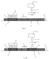
- Fig. 1A-1C illustrate an embodiment of the method according to the invention.
- Fig. 1A shows a grain-MOG mixture 1 containing a sample volume 2.
- the sample volume 2 is a part of the total volume of the grain-MOG mixture 1.
- Fig. 1 B shows a next step in the method according to the invention.
- the sample volume 2 of the grain-MOG mixture 1 is subjected to a thermal excitation, e.g. heating or cooling.
- a thermal excitator 10 is provided to carry out the thermal excitation.
- Fig. 1C shows a further step in the method according to the invention.
- a thermal image 14 is generated at an imaging location 6.
- the thermal excitation location 5 and the thermal imaging location 6 may coincide with each other.
- the thermal image 14 is generated of at least a surface of the sample volume 2 of the grain-MOG mixture 1 that has been subjected to the thermal excitation.
- the thermal image 14 is generated by a thermal imaging device 11.
- the thermal image 14 is processed by an image processor 12 that receives data from the thermal imaging device 11 via data connection 13.
- the data connection 13 can be a wired connection or a wireless connection.
- the thermal image 14 is processed and therewith data representing the temperature distribution over the thermal image 14 is obtained. In the example of fig. 1C , this results in a thermal image 14 which shows a generally uniform background color 15, and some spots 16 with a different temperature.
- multiple thermal images are generated, e.g. intermittently, in order to monitor the temperature change over time within the sample volume 2.
- the subsequent step in the method according to the invention is to relate the temperature distribution to the share of the kernel fraction in the grain-MOG mixture.
- the background temperature 15 generally corresponds to the temperature that -given the amount of transferred thermal energy in the thermal excitation- can be expected for the kernels.
- the different temperature 16 generally corresponds to the temperature that -given the amount of transferred thermal energy in the thermal excitation-can be expected for chaff.
- Fig. 2A-2B illustrates a second embodiment of the method according to the invention.
- Fig. 2A shows a grain-MOG mixture 1 containing a sample volume 2.
- the grain-MOG mixture is transported in bulk form along a grain-MOG mixture path 4, in a direction of transport 3.
- the grain-MOG mixture 1 can move continuously or intermittently along the grain-MOG mixture path 4.
- the thermal excitation location 5 and the imaging location 6 are located along the grain-MOG mixture path 4.
- the imaging location 6 is arranged downstream of the thermal excitation location 5, as seen in the direction of movement 3 of the grain-MOG mixture 1 along the grain-MOG mixture path 4.
- the sample volume 2 of the grain-MOG mixture 1 is subjected to a thermal excitation, e.g. heating or cooling.
- a thermal excitator 10 is provided to carry out the thermal excitation.
- the thermal energy is transferred during the thermal excitation by the thermal excitator 10 to the sample volume 2 of the grain-MOG mixture in a modulated way, in the form of a pulse, in the form of a sinusoidal wave, in the form of a square pulse or in the form of a step.
- the sample volume 2 is a discreet ample volume, so upstream and downstream of the sample volume 2, there is grain-MOG mixture which is not subjected to the thermal excitation. This can for example be achieved by intermittent activation of the thermal excitator 10. It is however alternatively possible that the grain-MOG mixture does not contain discrete sample volumes.
- Fig. 2B shows that the sample volume 2 has moved along the grain-MOG mixture path 4 and has now reached the imaging location 6. Meanwhile, a next sample volume 2* has arrived at the thermal excitation location 5.
- a thermal image is generated.
- the thermal image is generated of at least a surface of the sample volume 2 of the grain-MOG mixture 1 that has been subjected to the thermal excitation.
- the thermal image is generated by a thermal imaging device 11.
- the thermal image is processed by an image processor 12 that receives data from the thermal imaging device 11 via data connection 13.
- the data connection 13 can be a wired connection or a wireless connection.
- the thermal image can be obtained using reflection, transmission or a combination of reflection and transmission.
- the thermal image is processed and therewith data representing the temperature distribution over the thermal image is obtained.
- the subsequent step in the method according to the invention is to relate the temperature distribution to the share of the kernel fraction in the grain-MOG mixture. This can be done in the same way as is described in relation to the embodiment of fig. 1A-1C .
- the thermal excitation location 5 is spaced apart from the imaging location 6.
- the surface temperature of the sample volume 2 will change towards the ambient temperature during the time between the thermal excitation and the generation of the thermal image if no measures are taken to prevent this.
- the kernels and the material other than grain do not only heat up at a mutually different rate, but they also cool down at a mutually different rate.
- the difference in expected temperature of the kernels and of the material other than grain, in particular of the chaff is larger during the cooling down period than during the warming up period. It is advantageous to generate the thermal image when the expected temperature difference between the kernels and the material other than grain is the largest, because then the best distinction between the two can be made.
- the grain-MOG-mixture is not moved along a grain-MOG path. Instead, the grain-MOG mixture remains stationary during the analysis.
- the thermal excitation location 5 and the thermal imaging location 6 coincide with each other.
- multiple thermal images of the sample volume are generated over time, so that the response of the kernel fraction and/or the MOG fraction over time to the thermal excitation can be obtained. This increases the accuracy and reliability of the analysis, as the kernels and the MOG show a different temperature profile in response to thermal excitation.
- Fig. 3 illustrates a third embodiment of the method according to the invention.
- the embodiment of fig. 3 is similar to the embodiment of fig. 2A-2B .
- the difference is that an optical imaging device 17 is provided in addition to the thermal excitator 10 and the thermal imaging device 11.
- the optical imaging device 17 is connected to the image processor via data connection 18.
- Data connection 18 can be a wired connection or a wireless connection.
- a sample volume 2 is subjected to a thermal excitation followed by the generation of a thermal image in the same way as was described in relation to the embodiments of fig. 1A-1C and fig. 2A-B .
- an optical analysis is carried out on the sample volume 2, e.g. in accordance with US2009/0297040 .
- the optical analysis can be carried out prior to the thermal excitation, after the thermal imaging or between the thermal excitation and the thermal imaging or simultaneously with the thermal imaging.
- whitecaps will look generally the same as chaff, because a whitecap has chaff material at its outer surface.
- the share of whitecaps in the grain-MOG mixture can be determined.
- the share of the whitecaps subfraction will be incorporated in the result for the share of the overall kernel fraction.
- the share of the whitecaps subfraction will be incorporated in the share of the chaff fraction.
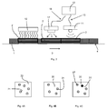
- Fig. 4A-4C illustrates the combination of thermal and optical imaging for the detection of whitecaps.
- Fig. 4A shows an example of an image of a sample volume 2 that is obtained using optical imaging, e.g. using the method of US2009/0297040 .
- the white background area 20 is recognized as being the kernel fraction of the grain-MOG mixture, while the grey circles 21 .schematically indicate regions being recognized as chaff.
- Fig. 4B shows an example of an image of a sample volume 2 that is obtained using thermal imaging in accordance with the invention.
- the white background area 20 is recognized as being the kernel fraction of the grain-MOG mixture, while the grey circles 21 .schematically indicate regions being recognized as chaff.
- Fig. 4C shows the result of the combined analysis: the white background area 20 represents the kernel fraction, the grey circles 21 represent chaff and the black circle 22 represents the whitecaps.
- Fig. 5 illustrates a combine harvester 50 in which the method according to the invention can be applied.
- the combine harvester 50 comprises a header 51 for harvesting crop, e.g. by cutting it loose from the field.
- the harvester crop is collected and transported internally via a crop inlet 56 to a processing device 52 inside the combine harvester 50.
- the processing device 52 which is adapted and arranged to receive harvested crop from the crop inlet 56.
- the processing device 52 comprises a thresher, a grain-MOG mixture discharge and a waste discharge (see fig. 6 ).
- the processing device 52 is adapted to thresh the harvested crop to obtain a grain-MOG mixture comprising a kernel fraction.
- the processing unit may comprise a separation unit and/or a cleaning unit.
- the combine harvester further comprises a grain tank 55 adapted for accommodating the grain-MOG mixture.
- the combine harvester further comprises a grain conveyor assembly 57, extending between the grain-MOG mixture discharge and the grain tank inlet along a grain-MOG mixture path 4.
- the grain conveyor assembly 57 is adapted to convey the grain-MOG mixture from the grain-MOG mixture discharge to the grain tank inlet along the grain-MOG mixture path 4.
- the grain conveyor assembly 57 comprises a grain elevator 53 and a grain elevator bypass 54.
- Grain-MOG mixture is withdrawn from the grain elevator and drops through the grain elevator bypass 54 to a lower level than the level at which it was withdrawn from the grain elevator 53, and is then re-introduced into the grain elevator 53.
- the grain-MOG mixture in the grain elevator bypass 54 can for example be used to determine or monitor parameters of the grain-MOG mixture leaving the processing device 52.
- the grain-MOG mixture path 4 has a branch that extends through the grain elevator bypass 53.
- the combine harvester 50 as shown in fig. 5 further comprises a grain-MOG mixture composition sensor 70 with is adapted to determine the share of the kernel fraction in the grain-MOG mixture in accordance with the method according to the invention.
- Fig. 6 schematically illustrates an embodiment of an agricultural harvester in accordance with the invention.
- the elements shown in fig. 6 could be arranged for example in the combine harvester of fig. 5 .
- the agricultural harvester of fig. 6 comprises a crop inlet 60.
- a processing device 52 is present which is adapted and arranged to receive harvested crop from the crop inlet 60.
- the processing device 52 comprises a thresher 61, optionally combined with a separation unit and/or a cleaning unit 62, a grain-MOG mixture discharge 64 and a waste discharge 63.
- the processing device 52 is adapted to thresh the harvested crop to obtain a grain-MOG mixture comprising a kernel fraction and an MOG-fraction.
- the agricultural harvester further comprises a grain tank 55 adapted for accommodating said grain-MOG mixture.
- the grain tank 55 has a grain tank inlet 65.
- the agricultural harvester according to the example of fig. 6 further comprises a grain conveyor assembly 57, extending between the grain-MOG mixture discharge 64 and the grain tank inlet 65 along a grain-MOG mixture path 4.
- the grain conveyor assembly 57 is adapted to convey the grain-MOG mixture from the grain-MOG mixture discharge 64 to the grain tank inlet 65 along said grain-MOG mixture path 4.
- the grain conveyor assembly 57 comprises a grain elevator 53 and a grain elevator bypass 54.
- Grain-MOG mixture is withdrawn from the grain elevator and drops through the grain elevator bypass 54 to a lower level than the level at which it was withdrawn from the grain elevator 53, and is then re-introduced into the grain elevator 53.
- the grain-MOG mixture in the grain elevator bypass 54 can for example be used to determine or monitor parameters of the grain-MOG mixture leaving the processing device 52.
- the grain-MOG mixture path 4 has a branch that extends through the grain elevator bypass 53.
- the agricultural harvester according to the example of fig. 6 further comprises a grain-MOG mixture composition sensor 70 with is adapted to determine the share of the kernel fraction and/or the MOG-fraction in the grain-MOG mixture in accordance with the method according to the invention.
- the grain-MOG mixture composition sensor 70 comprises a thermal excitator 10, a thermal imaging device 11 and an image processing device 12.
- the thermal excitator 10 is arranged at a thermal excitation location 5 and is adapted to subject a sample volume of the grain-MOG mixture to a thermal excitation.
- the thermal excitator 10 may be adapted to transfer the thermal energy during the thermal excitation the sample volume of the grain-MOG mixture in a modulated way, in the form of a pulse, in the form of a square pulse, in the form of a sinusoidal wave, or in the form of a step.
- the thermal imaging device 11 is adapted to generate a thermal image at an imaging location 6 of at least a surface of the sample volume of the grain-MOG mixture that has been subjected to the thermal excitation.
- the thermal imaging device 11 may be for example a thermal line scanner or a thermal camera.
- the thermal imaging device 11 may be adapted to obtain the thermal image by scanning along a line in a transverse direction over the grain-MOG mixture path 4, or by taking a thermal image of an area of the grain-MOG mixture travelling on the grain-MOG mixture path 4, e.g. taking multiple thermal images in a intermittent way.
- the image processing device 12 is adapted to process the thermal image obtained by the thermal imaging device 11 to obtain data representing the temperature distribution over the thermal image, and to relate the temperature distribution to the share of the kernel fraction in the grain-MOG mixture.
- the thermal imaging device 11 is arranged spaced apart from and downstream of the thermal excitator seen 10 in the direction of conveyance of the grain-MOG mixture along the grain-MOG mixture path 4.
- the thermal excitator 10 and the thermal imaging device 11 are arranged at the grain elevator bypass 54 of the grain elevator 53.
- an optical imaging device 17 is provided. It is connected to the image processing device 12 by data connection 18, which may be a wired or wireless connection.
- the image processing device 12 is adapted to process data from the thermal imaging device 11 and from the optical imaging device 17, and to process this data in a combined way to determine the share of a white caps subfraction in the kernel fraction.
- the optical imaging device 17 is shown as being arranged downstream of the thermal imaging device 11.
- the optical imaging device 17 is arranged such that the thermal imaging device 11 and the optical imaging device 11 simultaneously generate an image of the same sample volume. This increases the accuracy and reliability of the analysis.
- the agricultural harvester comprises an engine 80, e.g. a combustion engine.
- the engine generates heat while it is running. This generated het can be used in the thermal excitation to heat up the sample volume of the grain-MOG mixture to be evaluated.
- a collection header 81 is provided at a heated surface of the engine.
- air is accommodated and heated by the heat that is generated by the engine.
- a duct 82 accommodates the heated air and takes the heated air from the header 81 to the thermal excitator 10.
- a fan or the like can be provided to effect this flow of heated air from the header 81 to the thermal excitator 10.
- the thermal excitator 10 comprises at least one of a halogen heat source, an inductive heat source, an infrared heat source, an electrical resistance heat source, a microwaves source, or friction heat generator, a peltier element, a source of air of a reduced temperature.
- the grain-MOG mixture in the grain elevator is kept stationary during the analysis by the grain-MOG mixture composition sensor.
Landscapes
- Life Sciences & Earth Sciences (AREA)
- Engineering & Computer Science (AREA)
- Health & Medical Sciences (AREA)
- Chemical & Material Sciences (AREA)
- Environmental Sciences (AREA)
- General Physics & Mathematics (AREA)
- Physics & Mathematics (AREA)
- Pathology (AREA)
- General Health & Medical Sciences (AREA)
- Immunology (AREA)
- Analytical Chemistry (AREA)
- Biochemistry (AREA)
- Food Science & Technology (AREA)
- Signal Processing (AREA)
- Multimedia (AREA)
- Medicinal Chemistry (AREA)
- Mechanical Engineering (AREA)
- Spectroscopy & Molecular Physics (AREA)
- Toxicology (AREA)
- Investigating Or Analyzing Materials Using Thermal Means (AREA)
- Investigating Materials By The Use Of Optical Means Adapted For Particular Applications (AREA)
Abstract
the method comprising the following steps:
- receiving a grain-MOG mixture,
- at a thermal excitation location, subjecting a sample volume of the grain-MOG mixture to a thermal excitation using a thermal excitator,
- generating a thermal image at an imaging location of at least a surface of the sample volume of the grain-MOG mixture that has been subjected to the thermal excitation,
- processing the thermal image and therewith obtaining data representing the temperature distribution over the thermal image,
- relating the temperature distribution to the share of the kernel fraction in the grain-MOG mixture.
Description
- The invention pertains to a method for determining the composition of a grain-MOG mixture. The invention also pertains to a device for analyzing the composition of a grain-MOG mixture (1) comprising a kernel fraction and an MOG-fraction.
- "MOG" is widely used in the art to refer to "material other than grain".
- Agricultural harvesters comprise a processing device that comprises a thresher. Harvested crop is introduced into the processing device in a raw form, in which stalks may still be present and the grain is still in the ears. The thresher separates grain kernels from other plant parts, such as stalks, ears, husks and the like. The threshed grain leaves the processing device to be transported to a storage facility, such as a grain tank. The separated MOG is discharged from the agricultural harvester. Often, the processing device additionally comprises one or more sieves, to improve the separation between grain kernels and MOG, with the objective to transport a little chaff and other undesired material to the grain tank along with the threshed grain.
- The effectiveness and efficiency of threshing is not easy to control as it depends on many variables and because it is hard to measure.
-
US2009/0297040 discloses a method and device for crop particle discrimination. This device and method can be used to determine how much chaff is present in the grain-MOG mixture that travels from the processing device to the grain tank. If too much chaff is present, the processing device is likely in need of re-adjustment of some of the processing parameters. - In
US2009/0297040 , an optical method is proposed to discriminate between grain kernels and chaff. It relies on the difference in reflectivity of the grain kernel and the chaff. - It is the aim of the invention to provide a method for analyzing the composition of a grain-MOG mixture, in particular for determining the share of the kernel fraction of a grain-MOG mixture.
- This object is achieved by a method for analyzing the composition of a grain-MOG mixture comprising a kernel fraction and an MOG-fraction, the method comprising the following steps:
- receiving a grain-MOG mixture,
- at a thermal excitation location, subjecting a sample volume of the grain-MOG mixture to a thermal excitation using a thermal excitator,
- generating a thermal image at an imaging location of at least a surface of the sample volume of the grain-MOG mixture that has been subjected to the thermal excitation,
- processing the thermal image and therewith obtaining data representing the temperature distribution over the thermal image,
- relating the temperature distribution to the share of the kernel fraction and/or the MOG-fraction in the grain-MOG mixture.
- The grain-MOG mixture to be examined comprises kernels and other material. Other material in the grain-MOG mixture is for example chaff. Other plant materials such as parts of the ears and fragments of stalks or leaves may be present as well but in general the grain-MOG mixture will mainly be made up out of grain kernels and chaff.
- A special component that can be present in the grain-MOG mixture are "whitecaps". A "whitecap" is a piece of chaff in which a grain kernel is still present. So, in the threshing process the grain kernel is separated from the ear, but the separation between kernel and chaff did not take place.
- With many known techniques for discriminating between grain kernels and MOG such as chaff, whitecaps cannot properly be detected. For example, with the method that is disclosed in
US2009/0297040 , whitecaps will be seen as chaff, because of the reflectivity of the chaff piece that still surrounds the kernel of the whitecap. - In accordance with the invention, a sample volume of the grain-MOG mixture is analyzed in order to determine the share of kernels in the mixture.
- Kernels and materials other than grain, e.g. chaff, have a different heat capacity. At a given supply of thermal energy, the temperature change of a kernel is different from the temperature change of e.g. a piece of chaff. In general, a piece of chaff will heat up faster than a kernel.
- This principle is used to distinguish between kernels and material other than grain in the grain-MOG mixture.
- In accordance with the invention, after receiving a grain-MOG mixture, a sample volume of the grain-MOG mixture is subjected to a thermal excitation, e.g. the sample volume is heated or cooled. As e.g. heat will always penetrate into the grain-MOG mixture to some extent, it will be a volume of the grain-MOG mixture that is subjected to thermal excitation. The sample volume can be a part of the grain-MOG mixture or all of the grain-MOG mixture.
- The thermal excitation takes place at a thermal excitation location.
- The thermal excitation is carried out using a thermal excitator, which can be e.g. a heater, a cooler or a combined heater/cooler. Alternatively, other types of thermal excitation are used, e.g. induction or microwaves. The thermal excitator optionally comprises a thermal energy source, which is for example point-shaped, line-shaped or area-shaped.
- By thermal excitation of the grain-MOG mixture, temperature differences between kernels and material other than grain are created.
- As a subsequent step in the method according to the invention, a thermal image is generated of at least a surface of the sample volume of the grain-MOG mixture that has been subjected to the thermal excitation. This thermal image is generated at an imaging location. The imaging location may be different from the thermal excitation location or the imaging location may be the same as the thermal excitation location. The temperature difference between the kernels and the material other than grain that result from the thermal excitation will be captured on the thermal image that is generated.
- A subsequent step in the method according to the invention is processing the thermal image and therewith obtaining data representing the temperature distribution over the thermal image. In this step, data relating to local temperature differences in the sample volume that is imaged becomes available.
- Then, the temperature distribution in the sample volume of the grain-MOG mixture is related to the share of the kernel fraction in the grain-MOG mixture. This is for example done by obtaining the percentage of the total area of the thermal image that has a temperature that generally corresponds to the temperature that -given the amount of transferred thermal energy in the thermal excitation- can be expected for the kernels.
- Optionally, in addition or alternatively, the temperature distribution in the sample volume of the grain-MOG mixture is related to the share of the MOG- fraction in the grain-MOG mixture. This is for example done by obtaining the percentage of the total area of the thermal image that has a temperature that generally corresponds to the temperature that -given the amount of transferred thermal energy in the thermal excitation- can be expected for the kernels.
- The method according to the invention provides an elegant and efficient way of determining the share of kernels and/or MOG in a grain-MOG mixture.
- In a possible embodiment, multiple subsequent thermal images are generated of at least a surface of the sample volume of the grain-MOG mixture that has been subjected to the thermal excitation. This allows taking the temperature profile of the kernel fraction and/or of the MOG-fraction in response to the thermal excitation into account when making the distinction between the kernels and the MOG. This increases the accuracy and the reliability of the analysis, as kernels and MOG show a different temperature profile in response to thermal excitation.
- As already mentioned, in a possible embodiment, the imaging location and the thermal excitation location coincide with each other. i.e. the imaging location is the same as the thermal excitation location. Optionally, in such an embodiment, thermal excitation and thermal imaging take place simultaneously.
- In a possible embodiment, the grain-MOG mixture is moved along a grain-MOG mixture path. In this embodiment, the thermal excitation location and the imaging location are located along the grain-MOG mixture path. They can be at the same location or at different locations. When the thermal excitation location and the imaging location are at different location, then the imaging location can be directly downstream of the thermal excitation location (seen in the direction of transport of the grain-MOG mixture along the grain-MOG mixture path) or the thermal excitation location and the imaging location can be spaced apart from each other.
- In a possible embodiment, the thermal excitation is carried out in a modulated way, in the form of a pulse, in the form of a square pulse, in the form of a sinusoidal wave, or in the form of a step.
- In a possible embodiment, the thermal image is obtained by continuous measurements e.g. by scanning along a line, e.g. in a transverse direction over the grain-MOG mixture path in embodiments in which the grain-MOG mixture is moved along a grain-MOG mixture path, or by taking a thermal image of an area of the grain-MOG mixture.
- In a possible embodiment multiple thermal images are taken, e.g. in a intermittent way.
- The scanning along a line in a transverse direction over the grain-MOG mixture path can alternatively optionally be carried out in an intermittent way.
- In a possible embodiment, an ambient temperature is present in the vicinity of the grain-MOG mixture, and the thermal excitation results in the sample volume obtaining a surface temperature that is different from the ambient temperature. In this embodiment, the surface temperature of the sample volume changes or is allowed to change towards the ambient temperature during the time between the thermal excitation and the generation of the thermal image, e.g. during the transfer from the thermal excitation location to the imaging location.
- In an example of this embodiment, for example the sample volume is heated up during the thermal excitation, and then allowed to cool somewhat before the thermal image is generated. Due to their mutual difference in heat capacity the kernels and the material other than grain do not only heat up at a mutually different rate, but they also cool down at a mutually different rate. Depending on the exact curves for the temperature changes over time given a certain heat input and difference with ambient temperature, it is possible that at a certain point in time the difference in expected temperature of the kernels and of the material other than grain, in particular of the chaff, is larger during the cooling down period than during the warming up period. It is advantageous to generate the thermal image when the expected temperature difference between the kernels and the material other than grain is the largest, because then the best distinction between the two can be made.
- Of course, a similar situation may occur when the sample volume is cooled during the thermal excitation, and then allowed to heat up somewhat before the thermal image is generated.
- In a possible embodiment, the thermal excitation involves heating of the sample volume, using at least one of air of an elevated temperature, a halogen heat source, an infrared heat source, an inductive heat source, an electrical resistance heat source, microwaves, or friction heat e.g. induced by vibrations to which the sample volume is subjected.
- In a possible embodiment, the thermal excitation involves cooling of the sample volume, using at least one of air of a reduced temperature or a peltier element.
- In a possible embodiment, the thermal excitation involves both cooling and heating of the sample volume of the grain-MOG mixture.
- In a possible embodiment, the thermal image is generated using reflection. In an alternative embodiment, the thermal image is generated using transmission. In an alternative embodiment, the thermal image is generated using reflection and transmission.
- In a possible embodiment, the grain-MOG mixture further comprises a chaff fraction, and the method further comprises the step of relating the temperature distribution to the share of the chaff fraction in the grain-MOG mixture.
- In this embodiment, this is for example done by obtaining the percentage of the total area of the thermal image that has a temperature that generally corresponds to the temperature that -given the amount of transferred thermal energy in the thermal excitation-can be expected for the chaff. So, in this embodiment, the share of the kernel fraction and the share of the chaff fraction in the total sample volume of the grain-MOG mixture are obtained independently from each other.
- In a possible embodiment, the kernel fraction comprises a clean kernel subfraction and a white caps subfraction, and the share of the white caps subfraction is determined based on a combination of the thermal imaging and optical imaging.
- The heat capacity of clean kernels, not being encapsulated in chaff any more and the heat capacity of whitecaps are very similar which makes them hard to distinguish from each other using a thermal method e.g. as in accordance with the invention; clean kernels and whitecaps will look generally the same on a thermal image.
- On the other hand, with optical methods as for example described in
US2009/0297040 , whitecaps will look generally the same as chaff, because a whitecap has chaff material at its outer surface. - By combining the method according to the invention and an optical method, e.g. the optical method of
US2009/0297040 , the share of whitecaps in the grain-MOG mixture can be determined. In the thermal method according to the invention, the share of the whitecaps subfraction will be incorporated in the result for the share of the overall kernel fraction. In the result of the optical method, the share of the whitecaps subfraction will be incorporated in the share of the chaff fraction. - For example, say that the thermal method gives a result of 97% kernel fraction and 3% chaff fraction, and the optical method gives a result of 95% kernel fraction and 5% chaff fraction, the whitecaps subfraction will be 2%.
- In a variant, in this embodiment the thermal method further comprises the step of relating the temperature distribution to the share of the chaff fraction in the grain-MOG mixture so the share of the kernel fraction and the share of the chaff fraction in the total sample volume of the grain-MOG mixture are obtained independently from each other by thermal imaging.
- In a possible embodiment, during the thermal excitation, thermal energy is transferred by the thermal excitator to the sample volume of the grain-MOG mixture in a modulated way, in the form of a pulse, in the form of a square pulse, in the form of a sinusoidal wave, or in the form of a step.
- The invention further pertains to a device for analyzing the composition of a grain-MOG-mixture. The device according to the invention comprises a grain-MOG mixture composition sensor. The grain-MOG mixture composition sensor of the agricultural harvester according to the invention comprises:
- a thermal excitator, being arranged at a thermal excitation location and being adapted to subject a sample volume of the grain-MOG mixture to a thermal excitation,
- a thermal imaging device, being adapted to generate a thermal image at an imaging location of at least a surface of the sample volume of the grain-MOG mixture that has been subjected to the thermal excitation,
- an image processing device, being adapted to process the thermal image obtained by the thermal imaging device to obtain data representing the temperature distribution over the thermal image, and to relate the temperature distribution to the share of the kernel fraction and/or of the MOG-fraction in the grain-MOG mixture.
- In a possible embodiment, the thermal imaging device is adapted to generate multiple subsequent thermal images of at least a surface of the sample volume of the grain-MOG mixture that has been subjected to the thermal excitation.
- In a possible embodiment, the grain-MOG mixture composition sensor comprises multiple thermal imaging devices.
- In a possible embodiment, the imaging location and the thermal excitation location coincide with each other.
- In a possible embodiment, the thermal excitator is adapted to transfer the thermal energy during the thermal excitation the sample volume of the grain-MOG mixture in a modulated way, in the form of a pulse, in the form of a square pulse, in the form of a sinusoidal wave, or in the form of a step.
- In a possible embodiment, the thermal imaging device is adapted to obtain the thermal image by continuous measurements e.g. by scanning along a line, e.g. in a transverse direction over a grain-MOG mixture path, or by taking a thermal image of an area of the grain-MOG mixture travelling.
- For example, the thermal imaging device is a thermal line scanner or a thermal camera.
- In a possible embodiment, multiple thermal images are taken, e.g. in an intermittent way.
- In a possible embodiment, the thermal excitator and thermal imaging device are arranged along a grain-MOG mixture path.
- Optionally, the thermal imaging device is arranged spaced apart from and downstream of the thermal excitator seen in the direction of conveyance of the grain-MOG mixture along a grain-MOG mixture path.
- In a possible embodiment, the device according to the invention further comprises an optical imaging device. Optionally, the optical imaging device is an optical imaging device in accordance with
US2009/0297040 . - Optionally, the image processing device is adapted to process data from the thermal imaging device and from the optical imaging device, and to process this data in a combined way to determine the share of a white caps subfraction in the kernel fraction.
- In a possible embodiment, the thermal excitator comprises at least one of at least one of a halogen heat source, an infrared heat source, an inductive heat source, an electrical resistance heat source, a microwaves source, or friction heat generator, a peltier element, a source of air of a reduced temperature.
- In a possible embodiment, the device according to the invention is arranged at a grain storage facility.
- The invention further pertains to an agricultural harvester, comprising
- a crop inlet,
- a processing device which is adapted and arranged to receive harvested crop from the crop inlet, said processing device comprising a thresher, a grain-MOG mixture discharge and a waste discharge, wherein the processing device is adapted to thresh the harvested crop to obtain a grain-MOG mixture comprising a kernel fraction,
- a grain tank adapted for accommodating said grain-MOG mixture, said grain tank having a grain tank inlet,
- a grain conveyor assembly, extending between the grain-MOG mixture discharge and the grain tank inlet along a grain-MOG mixture path, which is adapted to convey the grain-MOG mixture from the grain-MOG mixture discharge to the grain tank inlet along said grain-MOG mixture path,
- a device for analyzing the composition of a grain-MOG mixture in accordance with the invention.
- Optionally, the agricultural harvester is a combine harvester.
- Optionally, the agricultural harvester is a thresher device, either a mobile thresher device or a stationary thresher device.
- The method according to the invention can advantageously be applied in an agricultural harvester that comprises a thresher and optionally a sieve device and/or other separator device adapted to separate kernels from loose chaff. By monitoring the grain-MOG mixture that leaves the thresher and/or sieve device using the method of the invention, the threshing performance and/or sieving performance can be measured and/or monitored. Optionally, the results of the measuring and/or monitoring obtained by the method according to the invention can be used to control the threshing and/or the sieving.
- In a possible embodiment, the grain conveyor assembly comprises a grain elevator, optionally including a grain elevator bypass, and the thermal excitator and the thermal imaging device are arranged at the grain elevator, optionally at the grain elevator bypass.
- Optionally, a thermal excitator and thermal imaging device of the grain-MOG mixture composition sensor in accordance with the invention and the optical imaging device are arranged at the grain elevator, optionally at a grain elevator bypass of the agricultural harvester.
- In a possible embodiment, the agricultural harvester comprises an engine, and the thermal excitator comprises a duct which is adapted to accommodate air that has been heated by said engine. The heated air can then be used as a heat source by the thermal excitator.
- The invention will be described in more detail below under reference to the figures, in which in a non-limiting manner exemplary embodiments of the invention will be shown.
- In the figures:
-
Fig. 1A-1C : illustrate an embodiment of the method according to the invention, -
Fig. 2A-2B : illustrate a second embodiment of the method according to the invention, -
Fig. 3 : illustrates a third embodiment of the method according to the invention, -
Fig. 4A-4C : illustrate the combination of thermal and optical imaging, -
Fig. 5 : illustrates a combine harvester in which the method according to the invention can be applied, -
Fig. 6 : illustrates an embodiment of an agricultural harvester in accordance with the invention. -
Fig. 1A-1C illustrate an embodiment of the method according to the invention. -
Fig. 1A shows a grain-MOG mixture 1 containing asample volume 2. In this embodiment, thesample volume 2 is a part of the total volume of the grain-MOG mixture 1. -
Fig. 1 B shows a next step in the method according to the invention. At athermal excitation location 5, thesample volume 2 of the grain-MOG mixture 1 is subjected to a thermal excitation, e.g. heating or cooling. Athermal excitator 10 is provided to carry out the thermal excitation. -
Fig. 1C shows a further step in the method according to the invention. Athermal image 14 is generated at animaging location 6. Thethermal excitation location 5 and thethermal imaging location 6 may coincide with each other. Thethermal image 14 is generated of at least a surface of thesample volume 2 of the grain-MOG mixture 1 that has been subjected to the thermal excitation. Thethermal image 14 is generated by athermal imaging device 11. Thethermal image 14 is processed by animage processor 12 that receives data from thethermal imaging device 11 viadata connection 13. Thedata connection 13 can be a wired connection or a wireless connection. - The
thermal image 14 is processed and therewith data representing the temperature distribution over thethermal image 14 is obtained. In the example offig. 1C , this results in athermal image 14 which shows a generallyuniform background color 15, and somespots 16 with a different temperature. Optionally, multiple thermal images are generated, e.g. intermittently, in order to monitor the temperature change over time within thesample volume 2. - The subsequent step in the method according to the invention is to relate the temperature distribution to the share of the kernel fraction in the grain-MOG mixture. In the example of
fig. 1C , thebackground temperature 15 generally corresponds to the temperature that -given the amount of transferred thermal energy in the thermal excitation- can be expected for the kernels. Thedifferent temperature 16 generally corresponds to the temperature that -given the amount of transferred thermal energy in the thermal excitation-can be expected for chaff. By calculating the percentage of the area of thethermal image 14 that has thebackground temperature 15, the share of the kernel fraction in the grain-MOG mixture 1 can be determined. By calculating the percentage of the area of thethermal image 14 that has thedifferent temperature 16, the share of the chaff fraction in the grain-MOG mixture 1 can be determined. -
Fig. 2A-2B illustrates a second embodiment of the method according to the invention. -
Fig. 2A shows a grain-MOG mixture 1 containing asample volume 2. The grain-MOG mixture is transported in bulk form along a grain-MOG mixture path 4, in a direction oftransport 3. The grain-MOG mixture 1 can move continuously or intermittently along the grain-MOG mixture path 4. - The
thermal excitation location 5 and theimaging location 6 are located along the grain-MOG mixture path 4. Theimaging location 6 is arranged downstream of thethermal excitation location 5, as seen in the direction ofmovement 3 of the grain-MOG mixture 1 along the grain-MOG mixture path 4. - At a
thermal excitation location 5, thesample volume 2 of the grain-MOG mixture 1 is subjected to a thermal excitation, e.g. heating or cooling. Athermal excitator 10 is provided to carry out the thermal excitation. - Optionally the thermal energy is transferred during the thermal excitation by the
thermal excitator 10 to thesample volume 2 of the grain-MOG mixture in a modulated way, in the form of a pulse, in the form of a sinusoidal wave, in the form of a square pulse or in the form of a step. - In
fig. 2A , thesample volume 2 is a discreet ample volume, so upstream and downstream of thesample volume 2, there is grain-MOG mixture which is not subjected to the thermal excitation. This can for example be achieved by intermittent activation of thethermal excitator 10. It is however alternatively possible that the grain-MOG mixture does not contain discrete sample volumes. -
Fig. 2B shows that thesample volume 2 has moved along the grain-MOG mixture path 4 and has now reached theimaging location 6. Meanwhile, anext sample volume 2* has arrived at thethermal excitation location 5. - At
imaging location 6, a thermal image is generated. The thermal image is generated of at least a surface of thesample volume 2 of the grain-MOG mixture 1 that has been subjected to the thermal excitation. The thermal image is generated by athermal imaging device 11. The thermal image is processed by animage processor 12 that receives data from thethermal imaging device 11 viadata connection 13. Thedata connection 13 can be a wired connection or a wireless connection. The thermal image can be obtained using reflection, transmission or a combination of reflection and transmission. - The thermal image is processed and therewith data representing the temperature distribution over the thermal image is obtained.
- The subsequent step in the method according to the invention is to relate the temperature distribution to the share of the kernel fraction in the grain-MOG mixture. This can be done in the same way as is described in relation to the embodiment of
fig. 1A-1C . - In the embodiment of
fig. 2A-2B , thethermal excitation location 5 is spaced apart from theimaging location 6. - If the thermal excitation results in the
sample volume 2 obtaining a surface temperature that is different from the ambient temperature in the vicinity of the grain-MOG mixture path 4, the surface temperature of thesample volume 2 will change towards the ambient temperature during the time between the thermal excitation and the generation of the thermal image if no measures are taken to prevent this. - This can be advantageous. Due to their mutual difference in heat capacity, the kernels and the material other than grain do not only heat up at a mutually different rate, but they also cool down at a mutually different rate. Depending on the exact curves for the temperature changes over time given a certain heat input and difference with ambient temperature, it is possible that at a certain point in time the difference in expected temperature of the kernels and of the material other than grain, in particular of the chaff, is larger during the cooling down period than during the warming up period. It is advantageous to generate the thermal image when the expected temperature difference between the kernels and the material other than grain is the largest, because then the best distinction between the two can be made.
- In a variant of the embodiment of
fig. 2A-2B , the grain-MOG-mixture is not moved along a grain-MOG path. Instead, the grain-MOG mixture remains stationary during the analysis. In this variant, thethermal excitation location 5 and thethermal imaging location 6 coincide with each other. Preferably, multiple thermal images of the sample volume are generated over time, so that the response of the kernel fraction and/or the MOG fraction over time to the thermal excitation can be obtained. This increases the accuracy and reliability of the analysis, as the kernels and the MOG show a different temperature profile in response to thermal excitation. -
Fig. 3 illustrates a third embodiment of the method according to the invention. - The embodiment of
fig. 3 is similar to the embodiment offig. 2A-2B . The difference is that anoptical imaging device 17 is provided in addition to the thermal excitator 10 and thethermal imaging device 11. Theoptical imaging device 17 is connected to the image processor viadata connection 18.Data connection 18 can be a wired connection or a wireless connection. - In the embodiment of
fig. 3 , asample volume 2 is subjected to a thermal excitation followed by the generation of a thermal image in the same way as was described in relation to the embodiments offig. 1A-1C andfig. 2A-B . In addition, an optical analysis is carried out on thesample volume 2, e.g. in accordance withUS2009/0297040 . The optical analysis can be carried out prior to the thermal excitation, after the thermal imaging or between the thermal excitation and the thermal imaging or simultaneously with the thermal imaging. - The results of the thermal imaging and the optical analysis are combined in order to detect whitecaps.
- The heat capacity of clean kernels, not being encapsulated in chaff any more and the heat capacity of whitecaps are very similar which makes them hard to distinguish from each other using a thermal method e.g. as in accordance with the invention; clean kernels and whitecaps will look generally the same on a thermal image.
- On the other hand, with optical methods as for example described in
US2009/0297040 , whitecaps will look generally the same as chaff, because a whitecap has chaff material at its outer surface. - By combining the method according to the invention and an optical method, e.g. the optical method of
US2009/0297040 , the share of whitecaps in the grain-MOG mixture can be determined. In the thermal method according to the invention, the share of the whitecaps subfraction will be incorporated in the result for the share of the overall kernel fraction. In the result of the optical method, the share of the whitecaps subfraction will be incorporated in the share of the chaff fraction. -
Fig. 4A-4C illustrates the combination of thermal and optical imaging for the detection of whitecaps. -
Fig. 4A shows an example of an image of asample volume 2 that is obtained using optical imaging, e.g. using the method ofUS2009/0297040 . Thewhite background area 20 is recognized as being the kernel fraction of the grain-MOG mixture, while the grey circles 21 .schematically indicate regions being recognized as chaff. -
Fig. 4B shows an example of an image of asample volume 2 that is obtained using thermal imaging in accordance with the invention. Thewhite background area 20 is recognized as being the kernel fraction of the grain-MOG mixture, while the grey circles 21 .schematically indicate regions being recognized as chaff. - Comparing the images of
fig. 4A and fig. 4B , it is clear that there is an area at the top right of the image that the optical imaging method designates as chaff and the thermal imaging method designates as kernels. As explained above, this is an indication that very likely whitecaps are present there. -
Fig. 4C shows the result of the combined analysis: thewhite background area 20 represents the kernel fraction, the grey circles 21 represent chaff and theblack circle 22 represents the whitecaps. - Of course,
fig. 4A-4C are very schematic representations, as in reality the images will be much more detailed, possibly even up to the level of showing individual grains. -
Fig. 5 illustrates acombine harvester 50 in which the method according to the invention can be applied. - The
combine harvester 50 comprises aheader 51 for harvesting crop, e.g. by cutting it loose from the field. The harvester crop is collected and transported internally via acrop inlet 56 to aprocessing device 52 inside thecombine harvester 50. - The
processing device 52 which is adapted and arranged to receive harvested crop from thecrop inlet 56. Theprocessing device 52 comprises a thresher, a grain-MOG mixture discharge and a waste discharge (seefig. 6 ). Theprocessing device 52 is adapted to thresh the harvested crop to obtain a grain-MOG mixture comprising a kernel fraction. In addition, the processing unit may comprise a separation unit and/or a cleaning unit. - The combine harvester further comprises a
grain tank 55 adapted for accommodating the grain-MOG mixture. - The combine harvester further comprises a
grain conveyor assembly 57, extending between the grain-MOG mixture discharge and the grain tank inlet along a grain-MOG mixture path 4. Thegrain conveyor assembly 57 is adapted to convey the grain-MOG mixture from the grain-MOG mixture discharge to the grain tank inlet along the grain-MOG mixture path 4. - In the example of
fig. 5 , thegrain conveyor assembly 57 comprises agrain elevator 53 and agrain elevator bypass 54. Grain-MOG mixture is withdrawn from the grain elevator and drops through thegrain elevator bypass 54 to a lower level than the level at which it was withdrawn from thegrain elevator 53, and is then re-introduced into thegrain elevator 53. The grain-MOG mixture in thegrain elevator bypass 54 can for example be used to determine or monitor parameters of the grain-MOG mixture leaving theprocessing device 52. The grain-MOG mixture path 4 has a branch that extends through thegrain elevator bypass 53. - The
combine harvester 50 as shown infig. 5 further comprises a grain-MOGmixture composition sensor 70 with is adapted to determine the share of the kernel fraction in the grain-MOG mixture in accordance with the method according to the invention. -
Fig. 6 schematically illustrates an embodiment of an agricultural harvester in accordance with the invention. The elements shown infig. 6 could be arranged for example in the combine harvester offig. 5 . - The agricultural harvester of
fig. 6 comprises acrop inlet 60. Aprocessing device 52 is present which is adapted and arranged to receive harvested crop from thecrop inlet 60. Theprocessing device 52 comprises athresher 61, optionally combined with a separation unit and/or acleaning unit 62, a grain-MOG mixture discharge 64 and awaste discharge 63. Theprocessing device 52 is adapted to thresh the harvested crop to obtain a grain-MOG mixture comprising a kernel fraction and an MOG-fraction. - The agricultural harvester further comprises a
grain tank 55 adapted for accommodating said grain-MOG mixture. Thegrain tank 55 has agrain tank inlet 65. - The agricultural harvester according to the example of
fig. 6 further comprises agrain conveyor assembly 57, extending between the grain-MOG mixture discharge 64 and thegrain tank inlet 65 along a grain-MOG mixture path 4. Thegrain conveyor assembly 57 is adapted to convey the grain-MOG mixture from the grain-MOG mixture discharge 64 to thegrain tank inlet 65 along said grain-MOG mixture path 4. - In the example of
fig. 6 , thegrain conveyor assembly 57 comprises agrain elevator 53 and agrain elevator bypass 54. Grain-MOG mixture is withdrawn from the grain elevator and drops through thegrain elevator bypass 54 to a lower level than the level at which it was withdrawn from thegrain elevator 53, and is then re-introduced into thegrain elevator 53. The grain-MOG mixture in thegrain elevator bypass 54 can for example be used to determine or monitor parameters of the grain-MOG mixture leaving theprocessing device 52. The grain-MOG mixture path 4 has a branch that extends through thegrain elevator bypass 53. - The agricultural harvester according to the example of
fig. 6 further comprises a grain-MOGmixture composition sensor 70 with is adapted to determine the share of the kernel fraction and/or the MOG-fraction in the grain-MOG mixture in accordance with the method according to the invention. - In the example of
fig. 6 , the grain-MOGmixture composition sensor 70 comprises athermal excitator 10, athermal imaging device 11 and animage processing device 12. Thethermal excitator 10 is arranged at athermal excitation location 5 and is adapted to subject a sample volume of the grain-MOG mixture to a thermal excitation. - The
thermal excitator 10 may be adapted to transfer the thermal energy during the thermal excitation the sample volume of the grain-MOG mixture in a modulated way, in the form of a pulse, in the form of a square pulse, in the form of a sinusoidal wave, or in the form of a step. - The
thermal imaging device 11 is adapted to generate a thermal image at animaging location 6 of at least a surface of the sample volume of the grain-MOG mixture that has been subjected to the thermal excitation. Thethermal imaging device 11 may be for example a thermal line scanner or a thermal camera. - The
thermal imaging device 11 may be adapted to obtain the thermal image by scanning along a line in a transverse direction over the grain-MOG mixture path 4, or by taking a thermal image of an area of the grain-MOG mixture travelling on the grain-MOG mixture path 4, e.g. taking multiple thermal images in a intermittent way. - The
image processing device 12 is adapted to process the thermal image obtained by thethermal imaging device 11 to obtain data representing the temperature distribution over the thermal image, and to relate the temperature distribution to the share of the kernel fraction in the grain-MOG mixture. - In the example of
fig. 6 , thethermal imaging device 11 is arranged spaced apart from and downstream of the thermal excitator seen 10 in the direction of conveyance of the grain-MOG mixture along the grain-MOG mixture path 4. - In the embodiment of
fig. 6 , the thermal excitator 10 and thethermal imaging device 11 are arranged at thegrain elevator bypass 54 of thegrain elevator 53. - In the embodiment of
fig. 6 , anoptical imaging device 17 is provided. It is connected to theimage processing device 12 bydata connection 18, which may be a wired or wireless connection. Theimage processing device 12 is adapted to process data from thethermal imaging device 11 and from theoptical imaging device 17, and to process this data in a combined way to determine the share of a white caps subfraction in the kernel fraction. - In
fig. 6 , theoptical imaging device 17 is shown as being arranged downstream of thethermal imaging device 11. Optionally, theoptical imaging device 17 is arranged such that thethermal imaging device 11 and theoptical imaging device 11 simultaneously generate an image of the same sample volume. This increases the accuracy and reliability of the analysis. - In the embodiment of
fig, 6 , the agricultural harvester comprises anengine 80, e.g. a combustion engine. The engine generates heat while it is running. This generated het can be used in the thermal excitation to heat up the sample volume of the grain-MOG mixture to be evaluated. - In the example of
fig. 6 , acollection header 81 is provided at a heated surface of the engine. In theheader 81, air is accommodated and heated by the heat that is generated by the engine. Aduct 82 accommodates the heated air and takes the heated air from theheader 81 to thethermal excitator 10. A fan or the like can be provided to effect this flow of heated air from theheader 81 to thethermal excitator 10. - Alternatively or in addition, the
thermal excitator 10 comprises at least one of a halogen heat source, an inductive heat source, an infrared heat source, an electrical resistance heat source, a microwaves source, or friction heat generator, a peltier element, a source of air of a reduced temperature. - In a variant of the embodiment of
fig. 6 , the grain-MOG mixture in the grain elevator is kept stationary during the analysis by the grain-MOG mixture composition sensor.
Claims (20)
- Method for analyzing the composition of a grain-MOG mixture (1) comprising a kernel fraction and an MOG-fraction,
the method comprising the following steps:- receiving a grain-MOG mixture (1),- at a thermal excitation location (5), subjecting a sample volume (2) of the grain-MOG mixture (1) to a thermal excitation using a thermal excitator (10),- generating a thermal image at an imaging location (6) of at least a surface of the sample volume (2) of the grain-MOG mixture (1) that has been subjected to the thermal excitation,- processing the thermal image and therewith obtaining data representing the temperature distribution over the thermal image,- relating the temperature distribution to the share of the kernel fraction and/or the MOG-fraction in the grain-MOG mixture (1). - Method according to claim 1,
wherein multiple subsequent thermal images are generated of at least a surface of the sample volume (2) of the grain-MOG mixture (1) that has been subjected to the thermal excitation. - Method according to any of the preceding claims,
wherein the imaging location (6) and the thermal excitation location (5) coincide with each other, with thermal excitation and thermal imaging taking place simultaneously. - Method according to any of the preceding claims,
wherein an ambient temperature is present in the vicinity of the grain-MOG mixture (1), and wherein the thermal excitation results in the sample volume (2) obtaining a surface temperature that is different from the ambient temperature,
and wherein the surface temperature of the sample volume (2) changes towards the ambient temperature during the time between the thermal excitation and the generation of the thermal image. - Method according to any of the preceding claims,
wherein the thermal excitation involves heating of the sample volume (2), using at least one of air of an elevated temperature, a halogen heat source, an infrared heat source, an inductive heat source, an electrical resistance heat source, microwaves, or friction heat, or wherein the thermal excitation involves cooling of the sample volume (2), using at least one of air of a reduced temperature or a peltier element. - Method according to any of the preceding claims,
wherein the grain-MOG mixture (1) further comprises a chaff fraction, and
wherein the method further comprises the step of relating the temperature distribution to the share of the chaff fraction in the grain-MOG mixture (1). - Method according to claim 6,
wherein the kernel fraction comprises a clean kernel subfraction and a white caps subfraction, and wherein the share of the white caps subfraction is determined based on a combination of the thermal imaging and optical imaging. - Method according to any of the preceding claims,
wherein the thermal excitation is carried out in a modulated way, in the form of a pulse, in the form of a square pulse, in the form of a sinusoidal wave, or in the form of a step. - Device for analyzing the composition of a grain-MOG mixture (1),
which device comprises a grain-MOG mixture composition sensor (70),
wherein the grain-MOG mixture composition sensor comprises:- a thermal excitator (10), being arranged at a thermal excitation location (5) and being adapted to subject a sample volume (2) of the grain-MOG mixture (1) to a thermal excitation,- a thermal imaging device (11), being adapted to generate a thermal image at an imaging location (6) of at least a surface of the sample volume (2) of the grain-MOG mixture (1) that has been subjected to the thermal excitation,- an image processing device (12), being adapted to process the thermal image obtained by the thermal imaging device (11) to obtain data representing the temperature distribution over the thermal image, and to relate the temperature distribution to the share of the kernel fraction and/or the MOG-fraction in the grain-MOG mixture (1). - Device according to claim 9,
wherein the thermal imaging device (11) is adapted to generate multiple subsequent thermal images of at least a surface of the sample volume (2) of the grain-MOG mixture (1) that has been subjected to the thermal excitation. - Device according to any of the claims 9-10,
wherein the grain-MOG mixture composition sensor comprises multiple thermal imaging devices (11). - Device according to any of the claims 9-11,
wherein the imaging location (6) and the thermal excitation location (5) coincide with each other. - Device according to any of the claims 9-12,
wherein the device further comprises an optical imaging device (17). - Device according to claim 13,
wherein the image processing device (12) is adapted to process data from the thermal imaging device (11) and from the optical imaging device (17), and to process this data in a combined way to determine the share of a white caps subfraction in the kernel fraction. - Device according to any of the claims 9-14,
wherein the thermal excitator (10) comprises at least one of a halogen heat source, an infrared heat source, an inductive heat source, an electrical resistance heat source, a microwaves sources, or friction heat generator, a peltier element, a source of air of a reduced temperature. - Device according to any of the claims 9-15,
wherein the thermal excitator (10) is adapted to carry out the excitation in a modulated way, in the form of a pulse, in the form of a square pulse, in the form of a sinusoidal wave, or in the form of a step. - Device according to any of the claims 9-16,
wherein the thermal imaging device(11) is adapted to obtain the thermal image by scanning along a line, or by in a intermittent way taking a thermal image of an area of the grain-MOG mixture (1). - Agricultural harvester, comprising- a crop inlet (63),- a processing device (52) which is adapted and arranged to receive harvested crop from the crop inlet (63), said processing device (52) comprising a thresher (61), a grain-MOG mixture discharge (64) and a waste discharge (63), wherein the processing device (52) is adapted to thresh the harvested crop to obtain a grain-MOG mixture (1) comprising a kernel fraction,- a grain tank (55) adapted for accommodating said grain-MOG mixture (1), said grain tank (55) having a grain tank inlet (65),- a grain conveyor assembly (57), extending between the grain-MOG mixture discharge (64) and the grain tank inlet (65) along a grain-MOG mixture path (4), which is adapted to convey the grain-MOG mixture (1) from the grain-MOG mixture discharge (64) to the grain tank inlet (65) along said grain-MOG mixture path (4),- a device for analyzing the composition of a grain-MOG mixture according to any of the claims 9-17.
- Agricultural harvester according to claim 18,
wherein the grain conveyor assembly comprises a grain elevator (53), optionally including a grain elevator bypass (54), and wherein the thermal excitator (10) and the thermal imaging device (11) are arranged at the grain elevator (53), optionally at the grain elevator bypass (54). - Agricultural harvester according to any of the claims 18-19,
wherein the agricultural harvester comprises an engine (80), and wherein the thermal excitator (10) comprises a duct (82) which is adapted to accommodate air that has been heated by said engine (80).
Applications Claiming Priority (1)
| Application Number | Priority Date | Filing Date | Title |
|---|---|---|---|
| BE201505517 | 2015-08-19 |
Publications (2)
| Publication Number | Publication Date |
|---|---|
| EP3133389A1 true EP3133389A1 (en) | 2017-02-22 |
| EP3133389B1 EP3133389B1 (en) | 2018-04-11 |
Family
ID=54834585
Family Applications (1)
| Application Number | Title | Priority Date | Filing Date |
|---|---|---|---|
| EP16184669.6A Active EP3133389B1 (en) | 2015-08-19 | 2016-08-18 | Method and device for analyzing the composition of a grain-mog mixture |
Country Status (3)
| Country | Link |
|---|---|
| US (1) | US10709066B2 (en) |
| EP (1) | EP3133389B1 (en) |
| BR (1) | BR102016019144A2 (en) |
Cited By (1)
| Publication number | Priority date | Publication date | Assignee | Title |
|---|---|---|---|---|
| US11605178B2 (en) | 2021-05-21 | 2023-03-14 | Cnh Industrial America Llc | White cap detection device |
Families Citing this family (2)
| Publication number | Priority date | Publication date | Assignee | Title |
|---|---|---|---|---|
| US10172285B2 (en) * | 2015-10-23 | 2019-01-08 | Carnegie Mellon University | System for evaluating agricultural material |
| US11160208B2 (en) * | 2019-04-29 | 2021-11-02 | Deere & Company | Method and apparatus for sensing crop material in a harvester |
Citations (5)
| Publication number | Priority date | Publication date | Assignee | Title |
|---|---|---|---|---|
| WO2002025236A1 (en) * | 2000-09-23 | 2002-03-28 | Fraunhofer-Gesellschaft zur Förderung der angewandten Forschung e.V. | Method and device for determining a temperature distribution of bulk material |
| WO2003058215A1 (en) * | 2002-01-09 | 2003-07-17 | Versuchs- Und Lehranstalt Für Brauerei In Berlin | Single grain analyser and method for analysing single grains |
| WO2006010761A1 (en) * | 2004-07-28 | 2006-02-02 | Cnh Belgium Nv | Apparatus and method for analysing the composition of crop in a crop-conveying machine |
| US20090297040A1 (en) | 2008-06-02 | 2009-12-03 | Missotten Bart M A | Crop particle discrimination methods and apparatus |
| CN103592316A (en) * | 2013-10-23 | 2014-02-19 | 江苏大学 | Method for detecting defects of potatoes |
Family Cites Families (7)
| Publication number | Priority date | Publication date | Assignee | Title |
|---|---|---|---|---|
| DE4317513A1 (en) | 1993-05-26 | 1994-12-01 | Select Ingenieurgesellschaft F | Method and device for selective separation of bodies and use of the method |
| US5480354A (en) * | 1994-11-03 | 1996-01-02 | Loral Corporation | Smart crop yield monitor |
| CA2615704A1 (en) * | 2005-07-11 | 2007-01-18 | De Beers Consolidated Mines Limited | Infrared imaging spectroscopy system and method for sorting particulate material |
| US8055054B2 (en) | 2006-12-15 | 2011-11-08 | General Electric Company | Method and apparatus for thermographic nondestructive evaluation of an object |
| ES2350665B1 (en) | 2008-12-02 | 2011-11-18 | Gestamp Vigo, S.A | PROCEDURE AND DEVICE FOR DETECTION OF EMBUTITION DEFECTS. |
| DE102011082908A1 (en) | 2011-09-19 | 2013-03-21 | Deere & Company | Method and arrangement for optically evaluating crops in a harvester |
| US9779330B2 (en) * | 2014-12-26 | 2017-10-03 | Deere & Company | Grain quality monitoring |
-
2016
- 2016-08-17 US US15/238,757 patent/US10709066B2/en active Active
- 2016-08-18 EP EP16184669.6A patent/EP3133389B1/en active Active
- 2016-08-18 BR BR102016019144A patent/BR102016019144A2/en active Search and Examination
Patent Citations (5)
| Publication number | Priority date | Publication date | Assignee | Title |
|---|---|---|---|---|
| WO2002025236A1 (en) * | 2000-09-23 | 2002-03-28 | Fraunhofer-Gesellschaft zur Förderung der angewandten Forschung e.V. | Method and device for determining a temperature distribution of bulk material |
| WO2003058215A1 (en) * | 2002-01-09 | 2003-07-17 | Versuchs- Und Lehranstalt Für Brauerei In Berlin | Single grain analyser and method for analysing single grains |
| WO2006010761A1 (en) * | 2004-07-28 | 2006-02-02 | Cnh Belgium Nv | Apparatus and method for analysing the composition of crop in a crop-conveying machine |
| US20090297040A1 (en) | 2008-06-02 | 2009-12-03 | Missotten Bart M A | Crop particle discrimination methods and apparatus |
| CN103592316A (en) * | 2013-10-23 | 2014-02-19 | 江苏大学 | Method for detecting defects of potatoes |
Non-Patent Citations (1)
| Title |
|---|
| DATABASE WPI Week 201430, Derwent World Patents Index; AN 2014-G24893, XP002755185 * |
Cited By (1)
| Publication number | Priority date | Publication date | Assignee | Title |
|---|---|---|---|---|
| US11605178B2 (en) | 2021-05-21 | 2023-03-14 | Cnh Industrial America Llc | White cap detection device |
Also Published As
| Publication number | Publication date |
|---|---|
| US10709066B2 (en) | 2020-07-14 |
| BR102016019144A2 (en) | 2017-02-21 |
| US20170049050A1 (en) | 2017-02-23 |
| EP3133389B1 (en) | 2018-04-11 |
Similar Documents
| Publication | Publication Date | Title |
|---|---|---|
| US10664726B2 (en) | Grain quality monitoring | |
| US11510364B2 (en) | Crop residue based field operation adjustment | |
| RU2566989C2 (en) | Device for registration and determining of bulk material composition | |
| RU2647087C2 (en) | Agricultural harvesting machine | |
| EP3133389B1 (en) | Method and device for analyzing the composition of a grain-mog mixture | |
| EP3138383B1 (en) | Agricultural harvester including feedback control of chopping parameters | |
| US8086378B2 (en) | Method for monitoring the quality of crop material | |
| US10455763B2 (en) | Harvest analysis system intended for use in a machine | |
| EP3485717A1 (en) | Acoustic material flow sensor | |
| US20080186487A1 (en) | Measuring device for optical and spectroscopic examination of a sample | |
| EP3135101B1 (en) | Monitoring system for an agricultural harvester and agricultural harvester | |
| CN104749189A (en) | Grain interior insect pest detection device based on multi-spectral imaging technology | |
| Jamil et al. | Husk detection using thermal imaging technology | |
| CN207571113U (en) | Agricultural product quality control system | |
| BE1022897B1 (en) | Apparatus for analyzing the composition of a grain & non-grain mixture | |
| Bejo-Khairunniza et al. | Paddy grading using thermal imaging technology | |
| EP4148415A1 (en) | Method and system for measuring threshing losses | |
| JP3728795B2 (en) | Shattered paddy detection equipment for threshing equipment | |
| US11605178B2 (en) | White cap detection device | |
| KR20240092767A (en) | System for determining defects in silkworm cocoons using near-infrared transmission spectrum | |
| JP2023542108A (en) | Method for determining the condition of crops transported by a root vegetable transport device | |
| JP2021103975A (en) | Harvester management system, harvester, and harvester management method | |
| Srivastava | Automated non-destructive machine vision system for internal inspection of rough rice |
Legal Events
| Date | Code | Title | Description |
|---|---|---|---|
| PUAI | Public reference made under article 153(3) epc to a published international application that has entered the european phase |
Free format text: ORIGINAL CODE: 0009012 |
|
| STAA | Information on the status of an ep patent application or granted ep patent |
Free format text: STATUS: THE APPLICATION HAS BEEN PUBLISHED |
|
| AK | Designated contracting states |
Kind code of ref document: A1 Designated state(s): AL AT BE BG CH CY CZ DE DK EE ES FI FR GB GR HR HU IE IS IT LI LT LU LV MC MK MT NL NO PL PT RO RS SE SI SK SM TR |
|
| AX | Request for extension of the european patent |
Extension state: BA ME |
|
| STAA | Information on the status of an ep patent application or granted ep patent |
Free format text: STATUS: REQUEST FOR EXAMINATION WAS MADE |
|
| 17P | Request for examination filed |
Effective date: 20170822 |
|
| RBV | Designated contracting states (corrected) |
Designated state(s): AL AT BE BG CH CY CZ DE DK EE ES FI FR GB GR HR HU IE IS IT LI LT LU LV MC MK MT NL NO PL PT RO RS SE SI SK SM TR |
|
| RIC1 | Information provided on ipc code assigned before grant |
Ipc: G01N 33/10 20060101ALI20170919BHEP Ipc: G01N 25/00 20060101AFI20170919BHEP |
|
| GRAP | Despatch of communication of intention to grant a patent |
Free format text: ORIGINAL CODE: EPIDOSNIGR1 |
|
| STAA | Information on the status of an ep patent application or granted ep patent |
Free format text: STATUS: GRANT OF PATENT IS INTENDED |
|
| INTG | Intention to grant announced |
Effective date: 20171114 |
|
| GRAS | Grant fee paid |
Free format text: ORIGINAL CODE: EPIDOSNIGR3 |
|
| GRAA | (expected) grant |
Free format text: ORIGINAL CODE: 0009210 |
|
| STAA | Information on the status of an ep patent application or granted ep patent |
Free format text: STATUS: THE PATENT HAS BEEN GRANTED |
|
| AK | Designated contracting states |
Kind code of ref document: B1 Designated state(s): AL AT BE BG CH CY CZ DE DK EE ES FI FR GB GR HR HU IE IS IT LI LT LU LV MC MK MT NL NO PL PT RO RS SE SI SK SM TR |
|
| REG | Reference to a national code |
Ref country code: GB Ref legal event code: FG4D |
|
| REG | Reference to a national code |
Ref country code: CH Ref legal event code: EP |
|
| REG | Reference to a national code |
Ref country code: AT Ref legal event code: REF Ref document number: 988583 Country of ref document: AT Kind code of ref document: T Effective date: 20180415 |
|
| REG | Reference to a national code |
Ref country code: IE Ref legal event code: FG4D |
|
| REG | Reference to a national code |
Ref country code: DE Ref legal event code: R096 Ref document number: 602016002357 Country of ref document: DE |
|
| REG | Reference to a national code |
Ref country code: FR Ref legal event code: PLFP Year of fee payment: 3 |
|
| REG | Reference to a national code |
Ref country code: NL Ref legal event code: MP Effective date: 20180411 |
|
| REG | Reference to a national code |
Ref country code: LT Ref legal event code: MG4D |
|
| PG25 | Lapsed in a contracting state [announced via postgrant information from national office to epo] |
Ref country code: NL Free format text: LAPSE BECAUSE OF FAILURE TO SUBMIT A TRANSLATION OF THE DESCRIPTION OR TO PAY THE FEE WITHIN THE PRESCRIBED TIME-LIMIT Effective date: 20180411 |
|
| PG25 | Lapsed in a contracting state [announced via postgrant information from national office to epo] |
Ref country code: AL Free format text: LAPSE BECAUSE OF FAILURE TO SUBMIT A TRANSLATION OF THE DESCRIPTION OR TO PAY THE FEE WITHIN THE PRESCRIBED TIME-LIMIT Effective date: 20180411 Ref country code: FI Free format text: LAPSE BECAUSE OF FAILURE TO SUBMIT A TRANSLATION OF THE DESCRIPTION OR TO PAY THE FEE WITHIN THE PRESCRIBED TIME-LIMIT Effective date: 20180411 Ref country code: BG Free format text: LAPSE BECAUSE OF FAILURE TO SUBMIT A TRANSLATION OF THE DESCRIPTION OR TO PAY THE FEE WITHIN THE PRESCRIBED TIME-LIMIT Effective date: 20180711 Ref country code: LT Free format text: LAPSE BECAUSE OF FAILURE TO SUBMIT A TRANSLATION OF THE DESCRIPTION OR TO PAY THE FEE WITHIN THE PRESCRIBED TIME-LIMIT Effective date: 20180411 Ref country code: NO Free format text: LAPSE BECAUSE OF FAILURE TO SUBMIT A TRANSLATION OF THE DESCRIPTION OR TO PAY THE FEE WITHIN THE PRESCRIBED TIME-LIMIT Effective date: 20180711 Ref country code: SE Free format text: LAPSE BECAUSE OF FAILURE TO SUBMIT A TRANSLATION OF THE DESCRIPTION OR TO PAY THE FEE WITHIN THE PRESCRIBED TIME-LIMIT Effective date: 20180411 Ref country code: ES Free format text: LAPSE BECAUSE OF FAILURE TO SUBMIT A TRANSLATION OF THE DESCRIPTION OR TO PAY THE FEE WITHIN THE PRESCRIBED TIME-LIMIT Effective date: 20180411 Ref country code: PL Free format text: LAPSE BECAUSE OF FAILURE TO SUBMIT A TRANSLATION OF THE DESCRIPTION OR TO PAY THE FEE WITHIN THE PRESCRIBED TIME-LIMIT Effective date: 20180411 |
|
| PG25 | Lapsed in a contracting state [announced via postgrant information from national office to epo] |
Ref country code: GR Free format text: LAPSE BECAUSE OF FAILURE TO SUBMIT A TRANSLATION OF THE DESCRIPTION OR TO PAY THE FEE WITHIN THE PRESCRIBED TIME-LIMIT Effective date: 20180712 Ref country code: HR Free format text: LAPSE BECAUSE OF FAILURE TO SUBMIT A TRANSLATION OF THE DESCRIPTION OR TO PAY THE FEE WITHIN THE PRESCRIBED TIME-LIMIT Effective date: 20180411 Ref country code: LV Free format text: LAPSE BECAUSE OF FAILURE TO SUBMIT A TRANSLATION OF THE DESCRIPTION OR TO PAY THE FEE WITHIN THE PRESCRIBED TIME-LIMIT Effective date: 20180411 Ref country code: RS Free format text: LAPSE BECAUSE OF FAILURE TO SUBMIT A TRANSLATION OF THE DESCRIPTION OR TO PAY THE FEE WITHIN THE PRESCRIBED TIME-LIMIT Effective date: 20180411 |
|
| REG | Reference to a national code |
Ref country code: AT Ref legal event code: MK05 Ref document number: 988583 Country of ref document: AT Kind code of ref document: T Effective date: 20180411 |
|
| PG25 | Lapsed in a contracting state [announced via postgrant information from national office to epo] |
Ref country code: PT Free format text: LAPSE BECAUSE OF FAILURE TO SUBMIT A TRANSLATION OF THE DESCRIPTION OR TO PAY THE FEE WITHIN THE PRESCRIBED TIME-LIMIT Effective date: 20180813 |
|
| REG | Reference to a national code |
Ref country code: DE Ref legal event code: R097 Ref document number: 602016002357 Country of ref document: DE |
|
| PG25 | Lapsed in a contracting state [announced via postgrant information from national office to epo] |
Ref country code: RO Free format text: LAPSE BECAUSE OF FAILURE TO SUBMIT A TRANSLATION OF THE DESCRIPTION OR TO PAY THE FEE WITHIN THE PRESCRIBED TIME-LIMIT Effective date: 20180411 Ref country code: CZ Free format text: LAPSE BECAUSE OF FAILURE TO SUBMIT A TRANSLATION OF THE DESCRIPTION OR TO PAY THE FEE WITHIN THE PRESCRIBED TIME-LIMIT Effective date: 20180411 Ref country code: AT Free format text: LAPSE BECAUSE OF FAILURE TO SUBMIT A TRANSLATION OF THE DESCRIPTION OR TO PAY THE FEE WITHIN THE PRESCRIBED TIME-LIMIT Effective date: 20180411 Ref country code: DK Free format text: LAPSE BECAUSE OF FAILURE TO SUBMIT A TRANSLATION OF THE DESCRIPTION OR TO PAY THE FEE WITHIN THE PRESCRIBED TIME-LIMIT Effective date: 20180411 Ref country code: EE Free format text: LAPSE BECAUSE OF FAILURE TO SUBMIT A TRANSLATION OF THE DESCRIPTION OR TO PAY THE FEE WITHIN THE PRESCRIBED TIME-LIMIT Effective date: 20180411 Ref country code: SK Free format text: LAPSE BECAUSE OF FAILURE TO SUBMIT A TRANSLATION OF THE DESCRIPTION OR TO PAY THE FEE WITHIN THE PRESCRIBED TIME-LIMIT Effective date: 20180411 |
|
| PLBE | No opposition filed within time limit |
Free format text: ORIGINAL CODE: 0009261 |
|
| STAA | Information on the status of an ep patent application or granted ep patent |
Free format text: STATUS: NO OPPOSITION FILED WITHIN TIME LIMIT |
|
| PG25 | Lapsed in a contracting state [announced via postgrant information from national office to epo] |
Ref country code: SM Free format text: LAPSE BECAUSE OF FAILURE TO SUBMIT A TRANSLATION OF THE DESCRIPTION OR TO PAY THE FEE WITHIN THE PRESCRIBED TIME-LIMIT Effective date: 20180411 |
|
| 26N | No opposition filed |
Effective date: 20190114 |
|
| PG25 | Lapsed in a contracting state [announced via postgrant information from national office to epo] |
Ref country code: MC Free format text: LAPSE BECAUSE OF FAILURE TO SUBMIT A TRANSLATION OF THE DESCRIPTION OR TO PAY THE FEE WITHIN THE PRESCRIBED TIME-LIMIT Effective date: 20180411 |
|
| PG25 | Lapsed in a contracting state [announced via postgrant information from national office to epo] |
Ref country code: LU Free format text: LAPSE BECAUSE OF NON-PAYMENT OF DUE FEES Effective date: 20180818 |
|
| REG | Reference to a national code |
Ref country code: IE Ref legal event code: MM4A |
|
| PG25 | Lapsed in a contracting state [announced via postgrant information from national office to epo] |
Ref country code: SI Free format text: LAPSE BECAUSE OF FAILURE TO SUBMIT A TRANSLATION OF THE DESCRIPTION OR TO PAY THE FEE WITHIN THE PRESCRIBED TIME-LIMIT Effective date: 20180411 |
|
| PG25 | Lapsed in a contracting state [announced via postgrant information from national office to epo] |
Ref country code: IE Free format text: LAPSE BECAUSE OF NON-PAYMENT OF DUE FEES Effective date: 20180818 |
|
| PG25 | Lapsed in a contracting state [announced via postgrant information from national office to epo] |
Ref country code: MT Free format text: LAPSE BECAUSE OF NON-PAYMENT OF DUE FEES Effective date: 20180818 |
|
| PG25 | Lapsed in a contracting state [announced via postgrant information from national office to epo] |
Ref country code: TR Free format text: LAPSE BECAUSE OF FAILURE TO SUBMIT A TRANSLATION OF THE DESCRIPTION OR TO PAY THE FEE WITHIN THE PRESCRIBED TIME-LIMIT Effective date: 20180411 |
|
| PG25 | Lapsed in a contracting state [announced via postgrant information from national office to epo] |
Ref country code: CH Free format text: LAPSE BECAUSE OF NON-PAYMENT OF DUE FEES Effective date: 20190831 Ref country code: LI Free format text: LAPSE BECAUSE OF NON-PAYMENT OF DUE FEES Effective date: 20190831 |
|
| PG25 | Lapsed in a contracting state [announced via postgrant information from national office to epo] |
Ref country code: MK Free format text: LAPSE BECAUSE OF NON-PAYMENT OF DUE FEES Effective date: 20180411 Ref country code: HU Free format text: LAPSE BECAUSE OF FAILURE TO SUBMIT A TRANSLATION OF THE DESCRIPTION OR TO PAY THE FEE WITHIN THE PRESCRIBED TIME-LIMIT; INVALID AB INITIO Effective date: 20160818 Ref country code: CY Free format text: LAPSE BECAUSE OF FAILURE TO SUBMIT A TRANSLATION OF THE DESCRIPTION OR TO PAY THE FEE WITHIN THE PRESCRIBED TIME-LIMIT Effective date: 20180411 |
|
| PG25 | Lapsed in a contracting state [announced via postgrant information from national office to epo] |
Ref country code: IS Free format text: LAPSE BECAUSE OF FAILURE TO SUBMIT A TRANSLATION OF THE DESCRIPTION OR TO PAY THE FEE WITHIN THE PRESCRIBED TIME-LIMIT Effective date: 20180811 |
|
| REG | Reference to a national code |
Ref country code: DE Ref legal event code: R082 Ref document number: 602016002357 Country of ref document: DE Representative=s name: KROHER STROBEL RECHTS- UND PATENTANWAELTE PART, DE |
|
| PGFP | Annual fee paid to national office [announced via postgrant information from national office to epo] |
Ref country code: BE Payment date: 20230824 Year of fee payment: 8 |
|
| PGFP | Annual fee paid to national office [announced via postgrant information from national office to epo] |
Ref country code: DE Payment date: 20240820 Year of fee payment: 9 |
|
| PGFP | Annual fee paid to national office [announced via postgrant information from national office to epo] |
Ref country code: GB Payment date: 20240822 Year of fee payment: 9 |
|
| PGFP | Annual fee paid to national office [announced via postgrant information from national office to epo] |
Ref country code: FR Payment date: 20240820 Year of fee payment: 9 |
|
| PGFP | Annual fee paid to national office [announced via postgrant information from national office to epo] |
Ref country code: IT Payment date: 20240731 Year of fee payment: 9 |