EP3133369A1 - A method for measuring a height map of multiple fields of view and combining them to a composite height map with minimized sensitivity to instrument drift - Google Patents
A method for measuring a height map of multiple fields of view and combining them to a composite height map with minimized sensitivity to instrument drift Download PDFInfo
- Publication number
- EP3133369A1 EP3133369A1 EP15181597.4A EP15181597A EP3133369A1 EP 3133369 A1 EP3133369 A1 EP 3133369A1 EP 15181597 A EP15181597 A EP 15181597A EP 3133369 A1 EP3133369 A1 EP 3133369A1
- Authority
- EP
- European Patent Office
- Prior art keywords
- fields
- height
- view
- route
- profilometer
- Prior art date
- Legal status (The legal status is an assumption and is not a legal conclusion. Google has not performed a legal analysis and makes no representation as to the accuracy of the status listed.)
- Granted
Links
Images








Classifications
-
- G—PHYSICS
- G01—MEASURING; TESTING
- G01B—MEASURING LENGTH, THICKNESS OR SIMILAR LINEAR DIMENSIONS; MEASURING ANGLES; MEASURING AREAS; MEASURING IRREGULARITIES OF SURFACES OR CONTOURS
- G01B11/00—Measuring arrangements characterised by the use of optical techniques
- G01B11/02—Measuring arrangements characterised by the use of optical techniques for measuring length, width or thickness
- G01B11/06—Measuring arrangements characterised by the use of optical techniques for measuring length, width or thickness for measuring thickness ; e.g. of sheet material
- G01B11/0608—Height gauges
-
- G—PHYSICS
- G01—MEASURING; TESTING
- G01B—MEASURING LENGTH, THICKNESS OR SIMILAR LINEAR DIMENSIONS; MEASURING ANGLES; MEASURING AREAS; MEASURING IRREGULARITIES OF SURFACES OR CONTOURS
- G01B11/00—Measuring arrangements characterised by the use of optical techniques
- G01B11/02—Measuring arrangements characterised by the use of optical techniques for measuring length, width or thickness
-
- G—PHYSICS
- G01—MEASURING; TESTING
- G01B—MEASURING LENGTH, THICKNESS OR SIMILAR LINEAR DIMENSIONS; MEASURING ANGLES; MEASURING AREAS; MEASURING IRREGULARITIES OF SURFACES OR CONTOURS
- G01B11/00—Measuring arrangements characterised by the use of optical techniques
- G01B11/24—Measuring arrangements characterised by the use of optical techniques for measuring contours or curvatures
-
- G—PHYSICS
- G01—MEASURING; TESTING
- G01B—MEASURING LENGTH, THICKNESS OR SIMILAR LINEAR DIMENSIONS; MEASURING ANGLES; MEASURING AREAS; MEASURING IRREGULARITIES OF SURFACES OR CONTOURS
- G01B9/00—Measuring instruments characterised by the use of optical techniques
- G01B9/02—Interferometers
- G01B9/0209—Low-coherence interferometers
-
- G—PHYSICS
- G01—MEASURING; TESTING
- G01B—MEASURING LENGTH, THICKNESS OR SIMILAR LINEAR DIMENSIONS; MEASURING ANGLES; MEASURING AREAS; MEASURING IRREGULARITIES OF SURFACES OR CONTOURS
- G01B2290/00—Aspects of interferometers not specifically covered by any group under G01B9/02
- G01B2290/65—Spatial scanning object beam
Definitions
- the invention relates to a method for measuring a height map of multiple fields of view on a surface of a substrate with an optical profilometer and combining them to a composite height map, the method comprises:
- US5987189A discloses a method of combining height profiles of adjacent sections of a test surface to produce a composite profile of the surface and consists of taking successive measurements of adjacent sections of the surface of the test sample by sequentially placing them within the field of view of the instrument and profiling them by phase shifting or vertical scanning.
- the x-y translation of the microscope between successive measurements from one section to the next adjacent section of the surface being profiled is carried out by overlapping such sections, so that spatial continuity is maintained between measurements.
- the height data generated for each section are then combined to form a larger image corresponding to the entire surface tested and discontinuities and/or errors introduced by the x-y translation process are corrected by normalizing the overlapping portions to a common reference plane.
- a plane is fitted through each set of measured heights in the overlapping regions and the tip, tilt and offset of each fitted plane are corrected to produce matching overlapping height data in adjacent sections.
- the measured height data for the balance of each section are then also corrected by the same difference in tip, tilt and offset to obtain a continuous normalized image.
- An optical measuring system will have height drift because of heating and expansion of the optical components and/or sample, from the moment of switch on of the illumination or by variation in the environment temperature.
- the height drift may stabilize as the system and/or sample approaches thermal equilibrium.
- normal operation of an optical system might include warm-up time. This may pre-empt thermal height drift effects in the system (but not in the sample unless the sample is warmed up as well over all locations to be measured); however this takes a large amount of time.
- Drift may have other causes as well, such as:
- a method for measuring a height map of multiple fields of view on a surface of a substrate with an optical profilometer and combining them to a composite height map comprises:
- the route comprises directions with a first and second directional component, the second directional component being substantially perpendicular to the first directional component, and sequentially moving of the profilometer relative to the surface in a) comprises at least one time moving forward and backward in both the first and second directional component during measuring height maps of fields.
- the fields may be better divided over the surface to minimize the sensitivity to height drifting of the profilometer.
- the route may also be defined in a third direction, corresponding to the height, perpendicular to the first and second direction.
- moving forward and backward in both the first and second directional component comprises moving forward and backward in the first direction at least two fields of view and moving forward and backward in the second direction (e.g. left or right) at least two fields of view.
- the fields of view may be better divided over the surface to minimize the sensitivity to height drifting of the profilometer.
- moving of the profilometer relative to the surface comprises at least two time moving forward and backward in both the first and second directional component during measuring height maps of fields of view.
- the sensitivity to height drifting of the profilometer may be further minimized which otherwise will give rise to errors in the composite height map.
- the route is configured to measure the fields of view in substantially random order.
- the route By configuring the route to measure the fields of view in substantially random order the sensitivity to height drifting of the profilometer may be minimized.
- the route has a spiral or spiral-like shape.
- the route By configuring the route to measure the fields of view in a spiral or spiral-like shape the sensitivity to height drifting of the profilometer may be minimized during combining the plurality of height maps.
- the method comprises measurement and/or re-measurement of edge fields of views positioned substantially near the edges of the surface in direct order to minimize the time and thereby the drift between these measurements.
- the global tilt reconstruction will be based on these fields only. By maximizing the distance between these fields while minimizing the time in between the measurements the global tilts error of the composite height map will be minimized.
- the route comprises crossing a centre of the multiple fields of view on the surface multiple times.
- the profilometer By crossing the centre of the multiple fields of view on the surface multiple times the sensitivity to height drifting of the profilometer may be minimized.
- the method comprises moving from a measured field to a subsequent to be measured field leaving one, two, three or even more fields in between.
- the route By configuring the route to move from field to field leaving one, two, three or even more fields in between the fields the sensitivity to height drifting of the profilometer may be minimized.
- a region of overlap or connection between neighbouring fields might be maintained and combining a plurality of height maps comprises using the region of overlap or connection (if maintained) to establish and correct for height differences between fields in order to produce the composite height map of the surface.
- a common height reference might be used to establish and correct for height differences between fields to produce the composite height map of the surface.
- a composite height map may be obtained.
- the method comprises using an algorithm to determine the route.
- the order of measurement determined by this algorithm is dependent on the distance from the geometric centre of the configuration of field of views (FOVs) on the surface.
- the algorithm first selects the FOV with the largest distance from the centre of the surface, and places this one as first in the measurement order. In the case that several fields are at the same distance the first chosen will depend on the addressing order of the coding language, but in essence this does not matter.
- the algorithm searches again for the most distant field from the centre, excluding the field that is already chosen, and places this in the measurement order. The process is repeated until all fields are chosen. The order might also be reversed as this gives nearly the same results.
- Algorithm 3 is somewhat more complicated. Here the concept is to work in FOV pairs in order to make sure that the fields in those pairs are as opposite of the geographic centre of the surface as possible.
- the first field is selected by looking for the maximum distance away from the centre.
- the next field is selected by looking for the closest field near the mirrored (about the centre) position of the first field.
- the first field of the second (and subsequently, all following pairs) pair is selected by seeking an FOV, the position of which minimizes the distance to the previous chosen field, while maximizing the distance to the centre.
- the second field of the new pair is again selected by seeking a FOV closest to the mirrored (about the centre) position of the first. The procedure is followed until all pairs are designated in the measurement sequence, and any remaining field is added to the measuring order as needed. The order might also be reversed as this gives nearly the same results.
- Algorithm 4 begins similarly to algorithm 3 in the method of selecting the first pair.
- the first FOV of the following new pair (and successive pairs) is selected by searching for the nearest FOV to a virtual position at a location at the same distance from the centre as the first field of the previous pair, but rotated 90 degrees clockwise about the centre.
- the second FOV of the new pair is again selected by seeking a FOV closest to the mirrored (about the centre) position of the first.
- the third pair (and all following pairs) are found by repeating the clockwise rotation, finding nearest FOV, and finding mirrored FOV procedure as above. Any remnant fields are added to the measurement sequence at the end. The order might also be reversed as this gives nearly the same results.
- Algorithm 5 embodies a concept quite different than the algorithms above.
- the 4 corner fields i.e. fields positioned substantially near the edges are measured sequentially; after this, the first corner field is re-measured, completing a circuit around the extremities of the shape.
- the reestablishment of the global orientation and tilt is based on these 5 fields alone.
- the designation of the corners is accomplished by simply finding the minima and maxima in X and Y of the multiple FOV centre coordinates and placing these FOVs on the measurement sequence list in the following order:
- the optical profiler is a white-light interferometer (WLI), phase-shifting interferometer (PSI), chromatic point sensor (CPS), points-from-focus/ shape-from-focus sensor (PFF/SFF), confocal microscope, structured illumination microscope (SIM), or laser interferometer microscope.
- WLI white-light interferometer
- PSI phase-shifting interferometer
- CPS chromatic point sensor
- PFF/SFF points-from-focus/ shape-from-focus sensor
- SIM structured illumination microscope
- laser interferometer microscope a laser interferometer microscope
- Figure 4 depicts a measurement sequence according to an embodiment of the invention.
- the sequence starts with successively measuring height maps of individual fields of view on the surface with the profilometer by sequentially moving the profilometer relative to the surface from field 1 to field 2 and so on to field 25 and measuring the height map of each field 1 to 25 to generate a corresponding height map.
- the method therefore comprises successively measuring height maps of fields of view on the surface with the profilometer by:
- a plurality of height maps of measured fields of view generated may be combined by normalizing said height maps to each other to produce a composite height map of the surface.
- a region of overlap L between neighbouring fields might be maintained and combining a plurality of height maps of measured fields of view comprises using the region of overlap to determine and correct for the height differences of the fields.
- a composite height map may be obtained.
- the route comprises directions with a first and second directional component, the second directional component (for example from left to right in figure 4 ) being substantially perpendicular to the first directional component (for example from bottom to top in figure 4 ).
- Sequentially moving of the profilometer relative to the surface comprises at least one time moving forward and backward in both the first and second directional component during measuring height maps of fields of view.
- the fields of view may be better divided over the surface to minimize the sensitivity to height drifting of the profilometer. For example in figure 4 moving from 1 to 2 comprises moving forward in the first direction and in the second direction. Subsequently, the movement from 3 to 4 comprises moving backward in the first direction and in the second direction.
- Moving forwards and backward in both the first and second directional component may comprise moving forward and backward in the first direction at least two fields and moving forward and backward (e.g. left or right) in the second direction at least two fields of view during the whole measurement sequence.
- moving from 6 to 7 comprises moving forward in the first direction at least two fields of view
- moving from 7 to 8 comprises moving forward in the second direction at least two fields of view.
- the movement from 3 to 4 comprises moving backward in the first direction and in the second direction at least two fields of view.
- the route in figure 4 may be configured to measure the fields of view in substantially random order. By configuring the route to measure the fields of view in substantially random order the sensitivity to height drifting of the profilometer may be minimized.
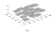
- Figure 5 depicts a simulated fields of view measurement on a flat using the sequence of figure 4 .
- Figure 6 depicts the simulated results after combining the dataset of figure 5 and shows the remaining tilt error. Comparing figure 6 with figure 3 shows that the remaining height error is substantially reduced in figure 6 by using the sequence of figure 4 .
- the route in figure 7 comprises moving forward and backward in both the first and second directional component at least one fields of view during the whole measurement sequence.
- moving from 5 to 6 comprises moving forward in the first direction one field and moving from 1 to 2 comprises moving forward in the second direction one field.
- the movement from 9 to 10 comprises moving backward in the first direction and the movement from 13 to 14 comprises moving backward in the first direction one field.
- the route has a spiral or spiral-like figure moving from 1 to 25 in figure 7 .
- the route By configuring the route to measure the fields of view in a spiral or spiral-like figure the sensitivity to height drifting of the profilometer may be minimized.
- Figure 8 depicts a simulated fields of view measurement on a flat using the sequence of figure 7 .
- Figure 9 depicts the simulated results after combining the dataset of figure 8 and shows the remaining tilt error. Comparing figure 9 with figure 3 shows that the remaining height error is substantially reduced in figure 9 by using the sequence of figure 8 .
- Figure 10 depicts a measurement sequence according to a further embodiment.
- the route comprises moving forward and backward in the first direction at least two fields of view and moving forward and backward (e.g. left or right) in the second direction at least two fields of view during the whole measurement sequence. It further comprises crossing a centre of the multiple fields of view 25 on the surface multiple times. By crossing the centre of the multiple fields of view on the surface multiple times the sensitivity to height drifting of the profilometer may be minimized.
- the route is configured to move from field to field leaving one, two, or even more fields of view in between. By configuring the route to move from field to field leaving one, two or even more fields of view in between the sensitivity to height drifting of the profilometer may be minimized.
- Figure 11 depicts a simulated fields of view measurement on a flat using the sequence of figure 10 .
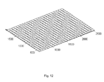
- Figure 12 depicts the simulated results after combining the dataset of figure 11 and shows the remaining tilt error. Comparing figure 12 with figure 3 shows that the remaining height error is substantially reduced in figure 12 by using the sequence of figure 10 .
- Figure 13 depicts a measurement sequence according to a further embodiment.
- the route comprising crossing the centre, moving forward and backward in the first and second direction at least one or two fields leaving one, two or even more fields of view in between the fields to minimize the sensitivity to height drifting.
- Figure 14 depicts a simulated fields of view measurement on a flat using the sequence of figure 13 .
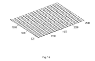
- Figure 15 depicts the simulated results after combining the dataset of figure 14 and shows the remaining tilt error. Comparing figure 15 with figure 3 shows that the remaining height error is substantially reduced in figure 15 by using the sequence of figure 13 .
- Figure 16 depicts a measurement sequence according to a further embodiment.
- the route comprising crossing the centre, moving forward and backward in the first and second direction at least one or two fields leaving one, two or even more fields of view in between the fields to minimize the sensitivity to height drifting.
- Figure 17 depicts a simulated fields of view measurement on a flat using the sequence of figure 16 .
- Figure 18 depicts the simulated results after combining the dataset of figure 17 and shows the remaining tilt error. Comparing figure 18 with figure 3 shows that the remaining height error is substantially reduced in figure 18 by using the sequence of figure 16 .
- Figure 19 and 20 depict a measurement sequence according to such a further embodiment.
- the route of figure 19 comprises measurement of edge fields of view 1, 2, 3 or 4 positioned substantially near the edges of the surface. Subsequently, the remaining fields of view are measured in figure 20 with a time efficient route 1 to 21.
- Figure 21 and 22 depict a simulated individual fields of view measurement on a flat using the sequence of figure 19 and 20 .
- Figure 23 depicts the simulated results of stitching the dataset of figure 21 and 22 , these are combined to form a single data set for stitching, but crucially the global orientation and tilt reconstruction is done only on the basis of the data in figure 21 , instead of the whole.
- Comparing figure 23 with figure 3 shows that the remaining height error is substantially reduced in figure 23 by using the sequence of figure 19 and 20 .
- the route of figure 19 comprises measurement of edge fields of view 1, 2, 3 or 4 positioned substantially near the edges of the surface.
- Figures 24 to 26 depict a measurement sequence according to a further embodiment.
- the route of figure 24 comprises measurement of edge fields of view 1, 2, 3 or 4 positioned substantially near the edges of the surface. Subsequently, the remaining fields of view are measured in figure 20 with a time efficient route 1 to 21.
- the route of figure 26 comprises re-measurement of edge fields of view 1, 2, 3 or 4 positioned substantially near the edges of the surface.
- Figures 27 to 29 depict a simulated individual fields of view measurement on a flat using the sequence of figures 24 to 26 and figure 30 depicts the simulated results of combining the dataset of figure 27 to 29 but only the data in figures 27 and 29 are used for reconstruction of global orientation and tilt and shows the remaining tilt error. Comparing figure 30 with figure 3 shows that the remaining height error is substantially reduced in figure 30 by using the sequence of figure 24 to 26 .
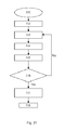
- a flow chart example of an automatic routing algorithm may be seen in figure 31 , on the basis that measurement order is determined by the distance to the center of the measurement area. Thus the fields that are furthest away are measured first, and measurement proceeds inwards, finishing (near to) the center point of the measurement area.
- Figure 31 depicts a flow chart example of an automatic routing algorithm.
- the automatic routing algorithm comprises:
- the optical profiler may be a white-light interferometer (WLI), phase-shifting interferometer (PSI), chromatic point sensor (CPS), points-from-focus/ shape-from-focus sensor (PFF/SFF), confocal microscope, structured illumination microscope (SIM), or laser interferometer microscope.
- WLI white-light interferometer
- PSI phase-shifting interferometer
- CPS chromatic point sensor
- PFF/SFF points-from-focus/ shape-from-focus sensor
- SIM structured illumination microscope
- laser interferometer microscope laser interferometer microscope
- the choice of routing option may be manually designated or automatically determined by algorithm through evaluating e.g. field of view configuration (including configuration shape), missing fields of view, field of view count, instrument status, magnitude of drift, or any other applicable factor.
- Pre-scan methods allow any routing, including random, for the final high precision measurements.
Landscapes
- Physics & Mathematics (AREA)
- General Physics & Mathematics (AREA)
- Length Measuring Devices By Optical Means (AREA)
Abstract
moving the profilometer relative to the surface from field to field along a route;
measuring height maps of fields on the surface along the route with the profilometer; and,
combining a plurality of height maps of measured fields by normalizing said height maps to each other to produce a composite height map of the surface; wherein the route is configured to minimize sensitivity to height drifting of the profilometer during combining a plurality of the height maps.
Description
- The invention relates to a method for measuring a height map of multiple fields of view on a surface of a substrate with an optical profilometer and combining them to a composite height map, the method comprises:
- moving the profilometer relative to the surface from field to field along a route;
- measuring height maps of fields on the surface along the route with the profilometer; and,
- combining a plurality of height maps of measured fields to produce a composite height map of the surface.
-
US5987189A discloses a method of combining height profiles of adjacent sections of a test surface to produce a composite profile of the surface and consists of taking successive measurements of adjacent sections of the surface of the test sample by sequentially placing them within the field of view of the instrument and profiling them by phase shifting or vertical scanning. The x-y translation of the microscope between successive measurements from one section to the next adjacent section of the surface being profiled is carried out by overlapping such sections, so that spatial continuity is maintained between measurements. The height data generated for each section are then combined to form a larger image corresponding to the entire surface tested and discontinuities and/or errors introduced by the x-y translation process are corrected by normalizing the overlapping portions to a common reference plane. - A plane is fitted through each set of measured heights in the overlapping regions and the tip, tilt and offset of each fitted plane are corrected to produce matching overlapping height data in adjacent sections. The measured height data for the balance of each section are then also corrected by the same difference in tip, tilt and offset to obtain a continuous normalized image.
- An optical measuring system will have height drift because of heating and expansion of the optical components and/or sample, from the moment of switch on of the illumination or by variation in the environment temperature.
- As time passes, the height drift may stabilize as the system and/or sample approaches thermal equilibrium. To avoid height drift effects, normal operation of an optical system might include warm-up time. This may pre-empt thermal height drift effects in the system (but not in the sample unless the sample is warmed up as well over all locations to be measured); however this takes a large amount of time.
- Drift may have other causes as well, such as:
- Ambient or instrument vibration
- Instability in the ambient measurement environment (e.g. variations in ambient air temperature, air pressure, or in other applicable factors)
- System creep
- In such a situation height stability will never be achieved completely and always some drift will remain which cannot be pre-empted by instrument warm-up.
- When fields are combined to measure a height map of a work piece larger than one field of view (FOV), drift will result in height offsets between the individual fields of view. An example may be found in a simulated measurement of an optical flat. The measurement is started from the lower left field of view and proceeds sequentially (See the measurement sequence in
figure 1 ). The simulated individual FOV measurements are shown infigure 2 . - Depending on the degrees of freedom in the combining algorithm, original global tilt and global orientation of the surface might be lost. Subsequently, the reconstruction of the global tilt and global orientation may be done by fitting a plane, for instance in a least-squares sense, to the individual measured fields. Depending on the measurement order (routing) the height offsets induced by the drift will then result in a global tilt error of the final result. An example of such a tilt error is shown in
figure 3 , which are the simulated results of stitching or combining the dataset offigure 2 . - It is therefore an objective of the invention to provide a method for measuring a height map of multiple fields of view on a surface of a substrate with an optical profilometer and combining them to a composite height map with minimized sensitivity to height drifting of the profilometer which otherwise will give rise to tilt errors in the composite height map.
- Accordingly there is provided a method for measuring a height map of multiple fields of view on a surface of a substrate with an optical profilometer and combining them to a composite height map, the method comprises:
- moving the profilometer relative to the surface from field to field along a route;
- measuring height maps of fields on the surface along the route with the profilometer; and, combining a plurality of height maps of measured fields to produce a composite height map of the surface, wherein the route is configured to minimize sensitivity to the effects caused by height drift of the profilometer during combining the plurality of height maps.
- By configuring the route the sensitivity of the combining multiple fields of view to a composite height map to height drift of the profilometer may be minimized which otherwise would give rise to tilt errors in the composite height map.
- According to a further embodiment the route comprises directions with a first and second directional component, the second directional component being substantially perpendicular to the first directional component, and sequentially moving of the profilometer relative to the surface in a) comprises at least one time moving forward and backward in both the first and second directional component during measuring height maps of fields.
- By at least one time moving forward and backward in both the first and second directional component during measuring height maps of fields, the fields may be better divided over the surface to minimize the sensitivity to height drifting of the profilometer.
- The route may also be defined in a third direction, corresponding to the height, perpendicular to the first and second direction.
- According to a further objective moving forward and backward in both the first and second directional component comprises moving forward and backward in the first direction at least two fields of view and moving forward and backward in the second direction (e.g. left or right) at least two fields of view.
- By at least moving forward and backward in both the first and second directional component at least two fields of view during measuring height maps of fields of view, the fields of view may be better divided over the surface to minimize the sensitivity to height drifting of the profilometer.
- According to a further embodiment moving of the profilometer relative to the surface comprises at least two time moving forward and backward in both the first and second directional component during measuring height maps of fields of view.
- By at least two time moving forward and backward in both the first and second directional component the sensitivity to height drifting of the profilometer may be further minimized which otherwise will give rise to errors in the composite height map.
- According to a further embodiment the route is configured to measure the fields of view in substantially random order.
- By configuring the route to measure the fields of view in substantially random order the sensitivity to height drifting of the profilometer may be minimized.
- According to a further embodiment the route has a spiral or spiral-like shape.
- By configuring the route to measure the fields of view in a spiral or spiral-like shape the sensitivity to height drifting of the profilometer may be minimized during combining the plurality of height maps.
- According to a further embodiment objective the method comprises measurement and/or re-measurement of edge fields of views positioned substantially near the edges of the surface in direct order to minimize the time and thereby the drift between these measurements. The global tilt reconstruction will be based on these fields only. By maximizing the distance between these fields while minimizing the time in between the measurements the global tilts error of the composite height map will be minimized.
- According to a further embodiment the route comprises crossing a centre of the multiple fields of view on the surface multiple times.
- By crossing the centre of the multiple fields of view on the surface multiple times the sensitivity to height drifting of the profilometer may be minimized.
- According to a further embodiment the method comprises moving from a measured field to a subsequent to be measured field leaving one, two, three or even more fields in between.
- By configuring the route to move from field to field leaving one, two, three or even more fields in between the fields the sensitivity to height drifting of the profilometer may be minimized.
- According to a further embodiment during measuring height maps of fields on the surface with the profilometer a region of overlap or connection between neighbouring fields might be maintained and combining a plurality of height maps comprises using the region of overlap or connection (if maintained) to establish and correct for height differences between fields in order to produce the composite height map of the surface. If no overlap or connection is maintained, a common height reference might be used to establish and correct for height differences between fields to produce the composite height map of the surface. Hereby a composite height map may be obtained.
- According to a further embodiment the method comprises using an algorithm to determine the route.
- Hereby a route may be determined whereby the sensitivity to height drifting of the profilometer may be minimized.
- Next a list of examples how to implement possible algorithms. This list is merely meant as examples and this invention does not exclude different variations, combination or different algorithms that serve the same purpose.
- The order of measurement determined by this algorithm is dependent on the distance from the geometric centre of the configuration of field of views (FOVs) on the surface. The algorithm first selects the FOV with the largest distance from the centre of the surface, and places this one as first in the measurement order. In the case that several fields are at the same distance the first chosen will depend on the addressing order of the coding language, but in essence this does not matter. Once the first field is chosen, the algorithm searches again for the most distant field from the centre, excluding the field that is already chosen, and places this in the measurement order. The process is repeated until all fields are chosen. The order might also be reversed as this gives nearly the same results.
- Similar to the previous algorithm, in this algorithm the FOV with the largest distance from the centre is located, and this is placed as first in the measurement order. However, the next field is determined by finding the maximum geometric distance from the location of the previous field, instead of the maximum field distance from the centre. This procedure is followed until all fields are allocated in the measurement sequence.The order might also be reversed as this gives nearly the same results.
-
Algorithm 3 is somewhat more complicated. Here the concept is to work in FOV pairs in order to make sure that the fields in those pairs are as opposite of the geographic centre of the surface as possible. - The first field, as in the algorithms above, is selected by looking for the maximum distance away from the centre. The next field is selected by looking for the closest field near the mirrored (about the centre) position of the first field. These two fields are added to the measurement sequence first.
- The first field of the second (and subsequently, all following pairs) pair is selected by seeking an FOV, the position of which minimizes the distance to the previous chosen field, while maximizing the distance to the centre. The second field of the new pair is again selected by seeking a FOV closest to the mirrored (about the centre) position of the first. The procedure is followed until all pairs are designated in the measurement sequence, and any remaining field is added to the measuring order as needed. The order might also be reversed as this gives nearly the same results.
-
Algorithm 4 begins similarly toalgorithm 3 in the method of selecting the first pair. However, the first FOV of the following new pair (and successive pairs) is selected by searching for the nearest FOV to a virtual position at a location at the same distance from the centre as the first field of the previous pair, but rotated 90 degrees clockwise about the centre. The second FOV of the new pair is again selected by seeking a FOV closest to the mirrored (about the centre) position of the first. - The third pair (and all following pairs) are found by repeating the clockwise rotation, finding nearest FOV, and finding mirrored FOV procedure as above. Any remnant fields are added to the measurement sequence at the end. The order might also be reversed as this gives nearly the same results.
-
Algorithm 5 embodies a concept quite different than the algorithms above. Here, the case of a rectangular configuration FOV shape, the 4 corner fields i.e. fields positioned substantially near the edges are measured sequentially; after this, the first corner field is re-measured, completing a circuit around the extremities of the shape. The reestablishment of the global orientation and tilt is based on these 5 fields alone. - The designation of the corners is accomplished by simply finding the minima and maxima in X and Y of the multiple FOV centre coordinates and placing these FOVs on the measurement sequence list in the following order:
- 1. (Xmin, Ymin)
- 2. (Xmax, Ymin)
- 3. (Xmax, Ymax)
- 4. (Xmin, Ymax)
- 5. The first field is then repeated.
- According to a further embodiment the optical profiler is a white-light interferometer (WLI), phase-shifting interferometer (PSI), chromatic point sensor (CPS), points-from-focus/ shape-from-focus sensor (PFF/SFF), confocal microscope, structured illumination microscope (SIM), or laser interferometer microscope.
- Embodiments of the invention will now be described, by way of example only, with reference to the accompanying schematic drawings in which corresponding reference symbols indicate corresponding parts, and in which:
-
Figure 1 depicts a measurement sequence; -
Figure 2 depicts a simulated individual field of view measurement on a flat using the sequence offigure 1 . -
Figure 3 depicts the simulated results of stitching the dataset offigure 2 and shows the remaining tilt error; -
Figure 4 depicts a measurement sequence according to an embodiment; -
Figure 5 depicts a simulated individual field of view measurement on a flat using the sequence offigure 4 ; -
Figure 6 depicts the simulated results of stitching the dataset offigure 5 and shows the remaining tilt error; -
Figure 7 depicts a measurement sequence according to a further embodiment; -
Figure 8 depicts a simulated individual field of view measurement on a flat using the sequence offigure 7 . -
Figure 9 depicts the simulated results of stitching the dataset offigure 8 and shows the remaining tilt error; -
Figure 10 depicts a measurement sequence according to yet a further embodiment; -
Figure 11 depicts a simulated individual field of view measurement on a flat using the sequence offigure 10 ; -
Figure 12 depicts the simulated results of stitching the dataset offigure 11 and shows the remaining tilt error; -
Figure 13 depicts a measurement sequence according to a further embodiment; -
Figure 14 depicts a simulated individual field of view measurement on a flat using the sequence offigure 13 ; -
Figure 15 depicts the simulated results of stitching the dataset offigure 14 and shows the remaining tilt error; -
Figure 16 depicts a measurement sequence according to a further embodiment; -
Figure 17 depicts a simulated individual field of view measurement on a flat using the sequence offigure 16 . -
Figure 18 depicts the simulated results of stitching the dataset offigure 17 and shows the remaining tilt error; -
Figure 19 and 20 depict a measurement sequence according to a fourth embodiment of the invention; -
Figure 21 and 22 depict a simulated individual field of view measurement on a flat using the sequence offigure 19 and 20 ; -
Figure 23 depicts the simulated results of stitching the dataset offigure 21 and 22 and shows the remaining tilt error; -
Figure 24 to 26 depict a measurement sequence according to a further embodiment; -
Figure 27 to 29 depict a simulated individual field of view measurement on a flat using the sequence offigure 24 to 26 ; and, -
Figure 30 depicts the simulated results of stitching the dataset offigure 27 to 29 and shows the remaining tilt error; -
Figure 31 depicts a flow chart example of an automatic routing algorithm; -
Figure 32 depicts an example of the use of an algorithm for 5 x 5 fields of view; -
Figure 33 depicts simulated fields of view measurement sets; and -
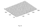
Figure 34 depicts the simulated stitching results with very little remnant tilt. -
Figure 4 depicts a measurement sequence according to an embodiment of the invention. The sequence starts with successively measuring height maps of individual fields of view on the surface with the profilometer by sequentially moving the profilometer relative to the surface fromfield 1 tofield 2 and so on to field 25 and measuring the height map of eachfield 1 to 25 to generate a corresponding height map. The method therefore comprises successively measuring height maps of fields of view on the surface with the profilometer by: - a1) measuring a height map of a
first field 1 on the surface with the profilometer; - a2) moving the profilometer relative to the surface from the first field to a
subsequent field 2; and, - a3) repeating a1 to a2) until multiple fields of view on the surface of the substrate have been measured with the optical profilometer to generate the corresponding height maps. Hereby multiple fields of view on the surface of the substrate may be measured.
- A plurality of height maps of measured fields of view generated may be combined by normalizing said height maps to each other to produce a composite height map of the surface. For this purpose a region of overlap L between neighbouring fields might be maintained and combining a plurality of height maps of measured fields of view comprises using the region of overlap to determine and correct for the height differences of the fields. Hereby a composite height map may be obtained.
- By configuring the route the sensitivity to height drifting of the profilometer may be minimized.
- The route comprises directions with a first and second directional component, the second directional component (for example from left to right in
figure 4 ) being substantially perpendicular to the first directional component (for example from bottom to top infigure 4 ). Sequentially moving of the profilometer relative to the surface comprises at least one time moving forward and backward in both the first and second directional component during measuring height maps of fields of view. By at least one time moving forward and backward in both the first and second directional component during measuring height maps of fields of view, the fields of view may be better divided over the surface to minimize the sensitivity to height drifting of the profilometer. For example infigure 4 moving from 1 to 2 comprises moving forward in the first direction and in the second direction. Subsequently, the movement from 3 to 4 comprises moving backward in the first direction and in the second direction. - Moving forwards and backward in both the first and second directional component may comprise moving forward and backward in the first direction at least two fields and moving forward and backward (e.g. left or right) in the second direction at least two fields of view during the whole measurement sequence. For example in
figure 4 moving from 6 to 7 comprises moving forward in the first direction at least two fields of view and moving from 7 to 8 comprises moving forward in the second direction at least two fields of view. The movement from 3 to 4 comprises moving backward in the first direction and in the second direction at least two fields of view. - The route in
figure 4 may be configured to measure the fields of view in substantially random order. By configuring the route to measure the fields of view in substantially random order the sensitivity to height drifting of the profilometer may be minimized. -
Figure 5 depicts a simulated fields of view measurement on a flat using the sequence offigure 4 .Figure 6 depicts the simulated results after combining the dataset offigure 5 and shows the remaining tilt error. Comparingfigure 6 withfigure 3 shows that the remaining height error is substantially reduced infigure 6 by using the sequence offigure 4 . - The route in
figure 7 comprises moving forward and backward in both the first and second directional component at least one fields of view during the whole measurement sequence. For example infigure 7 moving from 5 to 6 comprises moving forward in the first direction one field and moving from 1 to 2 comprises moving forward in the second direction one field. The movement from 9 to 10 comprises moving backward in the first direction and the movement from 13 to 14 comprises moving backward in the first direction one field. - The route has a spiral or spiral-like figure moving from 1 to 25 in
figure 7 . By configuring the route to measure the fields of view in a spiral or spiral-like figure the sensitivity to height drifting of the profilometer may be minimized. -
Figure 8 depicts a simulated fields of view measurement on a flat using the sequence offigure 7 .Figure 9 depicts the simulated results after combining the dataset offigure 8 and shows the remaining tilt error. Comparingfigure 9 withfigure 3 shows that the remaining height error is substantially reduced infigure 9 by using the sequence offigure 8 . -
Figure 10 depicts a measurement sequence according to a further embodiment. The route comprises moving forward and backward in the first direction at least two fields of view and moving forward and backward (e.g. left or right) in the second direction at least two fields of view during the whole measurement sequence. It further comprises crossing a centre of the multiple fields ofview 25 on the surface multiple times. By crossing the centre of the multiple fields of view on the surface multiple times the sensitivity to height drifting of the profilometer may be minimized. The route is configured to move from field to field leaving one, two, or even more fields of view in between. By configuring the route to move from field to field leaving one, two or even more fields of view in between the sensitivity to height drifting of the profilometer may be minimized. -
Figure 11 depicts a simulated fields of view measurement on a flat using the sequence offigure 10 .Figure 12 depicts the simulated results after combining the dataset offigure 11 and shows the remaining tilt error. Comparingfigure 12 withfigure 3 shows that the remaining height error is substantially reduced infigure 12 by using the sequence offigure 10 . -
Figure 13 depicts a measurement sequence according to a further embodiment. The route comprising crossing the centre, moving forward and backward in the first and second direction at least one or two fields leaving one, two or even more fields of view in between the fields to minimize the sensitivity to height drifting. -
Figure 14 depicts a simulated fields of view measurement on a flat using the sequence offigure 13 .Figure 15 depicts the simulated results after combining the dataset offigure 14 and shows the remaining tilt error. Comparingfigure 15 withfigure 3 shows that the remaining height error is substantially reduced infigure 15 by using the sequence offigure 13 . -
Figure 16 depicts a measurement sequence according to a further embodiment. The route comprising crossing the centre, moving forward and backward in the first and second direction at least one or two fields leaving one, two or even more fields of view in between the fields to minimize the sensitivity to height drifting. -
Figure 17 depicts a simulated fields of view measurement on a flat using the sequence offigure 16 .Figure 18 depicts the simulated results after combining the dataset offigure 17 and shows the remaining tilt error. Comparingfigure 18 withfigure 3 shows that the remaining height error is substantially reduced infigure 18 by using the sequence offigure 16 . - (Re-) measurement of certain fields of view positioned substantially near the edges of the surface in a direct time sequence at the extreme field positions (for example, the corner or on-axis fields), and basing global tilt and height retrieval on these fields of view alone may be considered. By maximizing the lateral distance while minimizing the time between measurements the tilt error is minimized.
-
Figure 19 and 20 depict a measurement sequence according to such a further embodiment. The route offigure 19 comprises measurement of edge fields ofview figure 20 with a timeefficient route 1 to 21. -
Figure 21 and 22 depict a simulated individual fields of view measurement on a flat using the sequence offigure 19 and 20 .Figure 23 depicts the simulated results of stitching the dataset offigure 21 and 22 , these are combined to form a single data set for stitching, but crucially the global orientation and tilt reconstruction is done only on the basis of the data infigure 21 , instead of the whole. - Comparing
figure 23 withfigure 3 shows that the remaining height error is substantially reduced infigure 23 by using the sequence offigure 19 and 20 . The route offigure 19 comprises measurement of edge fields ofview - By combining multiple repetitions of the sequence of fields to be used in the reconstruction the tilt error can be even further minimized.
Figures 24 to 26 depict a measurement sequence according to a further embodiment. The route offigure 24 comprises measurement of edge fields ofview figure 20 with a timeefficient route 1 to 21. The route offigure 26 comprises re-measurement of edge fields ofview -
Figures 27 to 29 depict a simulated individual fields of view measurement on a flat using the sequence offigures 24 to 26 andfigure 30 depicts the simulated results of combining the dataset offigure 27 to 29 but only the data infigures 27 and29 are used for reconstruction of global orientation and tilt and shows the remaining tilt error. Comparingfigure 30 withfigure 3 shows that the remaining height error is substantially reduced infigure 30 by using the sequence offigure 24 to 26 . - A flow chart example of an automatic routing algorithm may be seen in
figure 31 , on the basis that measurement order is determined by the distance to the center of the measurement area. Thus the fields that are furthest away are measured first, and measurement proceeds inwards, finishing (near to) the center point of the measurement area. -
Figure 31 depicts a flow chart example of an automatic routing algorithm. The automatic routing algorithm comprises: - 311 Input a list of field of view positions of a measurement area;
- 312 Determine all field of view distances from centrepoint of measurement area;
- 313 Determine and select field of views with maximum distance to centre;
- 314 Transfer selected field of views to measurement order list;
- 315 Remove selected field of views from Input list;
- 316 Smaller or equal 2 fields left? If not 313, if yes 317.
- 317 Add remaining fields to output list; and
- 318 Finish.
- According to an embodiment the automatic routing algorithm method comprises:
- input a list of field of view positions of a measurement area;
- determine all field of view distances from a centrepoint of measurement area;
- determine and select field of views with maximum distance to the centre;
- transfer selected field of views to a measurement order list; and,
- remove selected field of views from the input list.
- An example of the use of this algorithm for 5 x 5 FOV can result in the routing seen in
figure 32 , which is similar to the spiral routing shown infigure 13 . The simulated FOV measurement set that results is shown infigure 33 , with the simulated stitching results shown infigure 34 . Again, as in the similar stitching results infigure 15 ,figure 34 shows very little remnant tilt. Hereby a route may be determined whereby the sensitivity to height drifting of the profilometer may be minimized. - The optical profiler may be a white-light interferometer (WLI), phase-shifting interferometer (PSI), chromatic point sensor (CPS), points-from-focus/ shape-from-focus sensor (PFF/SFF), confocal microscope, structured illumination microscope (SIM), or laser interferometer microscope.
- The choice of routing option may be manually designated or automatically determined by algorithm through evaluating e.g. field of view configuration (including configuration shape), missing fields of view, field of view count, instrument status, magnitude of drift, or any other applicable factor.
- Any other routing options and algorithms that achieve the same goal may be considered.
- To ensure that the sample position is within the measurement height range of the sensor moving from one FOV to the next a feed forward method to predict the height of a neighbouring FOV might be used. It must be noted that if a feed-forward technique is to be used to enhance drift compensation, the choice of routing is limited to a spiral, as feed forward requires a field to be directly adjacent to a previous one, for fitting and extrapolation. As such, e.g. random routing will not work.
- As alternative to a feed forward method to control the z-position of the sample with respect to the sensor a pre-scan method might be used to provide a coarse (less accurate) map of the sample. Pre-scan methods allow any routing, including random, for the final high precision measurements.
- It is to be understood that the disclosed embodiments are merely exemplary of the invention, which can be embodied in various forms. Therefore, specific structural and functional details disclosed herein are not to be interpreted as limiting, but merely as a basis for the claims and as a representative basis for teaching one skilled in the art to variously employ the present invention in virtually any appropriately detailed structure. Furthermore, the terms and phrases used herein are not intended to be limiting, but rather, to provide an understandable description of the invention.
- The terms "a" or "an", as used herein, are defined as one or more than one. The term another, as used herein, is defined as at least a second or more. The terms including and/or having, as used herein, are defined as comprising (i.e., not excluding other elements or steps). Any reference signs in the claims should not be construed as limiting the scope of the claims or the invention. The mere fact that certain measures are recited in mutually different dependent claims does not indicate that a combination of these measures cannot be used to advantage. The scope of the invention is only limited by the following claims.
The order might also be reversed as this gives nearly the same results.
Claims (12)
- A method for measuring a height map of multiple fields of view on a surface of a substrate with an optical profilometer and combining them to a composite height map, the method comprises:moving the profilometer relative to the surface from field to field along a route;measuring height maps of fields on the surface along the route with the profilometer; and,combining a plurality of height maps of measured fields to produce a composite height map of the surface, wherein the route is configured to minimize sensitivity to the effects caused by height drift of the profilometer during combining the plurality of height maps.
- The method according to claim 1, wherein the route comprises directions with a first and second directional component, the second directional component being substantially perpendicular to the first directional component, and moving of the profilometer relative to the surface comprises at least one time moving forward and backward in both the first and second directional component during measuring the height maps of the fields of view.
- The method according to claim 2, wherein moving forward and backward in both the first and second directional component comprises moving forward and backward in the first direction at least two fields of view and moving forward and backward in the second direction at least two fields of view.
- The method according to any of claims 2 or 3, wherein moving of the profilometer relative to the surface comprises moving forward and backward in both the first and second directional component at least twice during measurement of the height maps of the fields of view.
- The method according to any of claims 1, 2, 3, or 4, wherein the route is configured to measure the fields in substantially random order.
- The method according to any of claims 1, 2, 3, 4, or 5, wherein the route has a spiral or spiral-like shape.
- The method according to any of the preceding claims, wherein the method comprises: measuring and/or re-measuring height maps of multiple fields of view positioned substantially near the edges of the surface in sequence and,
combining a plurality of height maps comprises using the re-measured fields of view to correct the composite height map afterwards for global orientation and tilt. - The method according to any of claims 1, 2, 3, 4, 5, 6 or 7, wherein the route comprises crossing a centre of the multiple fields on the surface multiple times.
- The method according to any of claims 1, 2, 3, 4, 5, 6, 7 or 8, wherein the method comprises moving from a measured field to a subsequent to be measured field leaving one, two, three or even more fields in between.
- The method according to any of the preceding claims, wherein the method comprises using an algorithm to determine the route.
- The method according to any of the preceding claims, wherein during the measurement of height maps of fields of view on the surface with the profilometer a region of overlap or connection between neighbouring fields of view might be maintained, and combining a plurality of height maps comprises using the region of overlap or individual field of view height information to determine and correct for height differences in order to produce the composite height map of the surface.
- The method according to any of the preceding claims, wherein the optical profiler is a white-light interferometer (WLI), phase-shifting interferometer (PSI), chromatic point sensor (CPS), points-from-focus/ shape-from-focus sensor (PFF/SFF), confocal microscope, structured illumination microscope (SIM), or laser interferometer microscope.
Priority Applications (4)
| Application Number | Priority Date | Filing Date | Title |
|---|---|---|---|
| EP15181597.4A EP3133369B1 (en) | 2015-08-19 | 2015-08-19 | Methods for measuring a height map of multiple fields of view and combining them to a composite height map with minimized sensitivity to instrument drift |
| US15/198,261 US10563974B2 (en) | 2015-08-19 | 2016-06-30 | Method for measuring a height map of multiple fields of view and combining them to a composite height map with minimized sensitivity to instrument drift |
| JP2016157971A JP6823399B2 (en) | 2015-08-19 | 2016-08-10 | How to measure height maps of multiple fields of view and combine them into a composite height map with minimal sensitivity to device drift |
| CN201610685793.4A CN106468534B (en) | 2015-08-19 | 2016-08-18 | Method for measuring height maps and merging height maps into a composite height map |
Applications Claiming Priority (1)
| Application Number | Priority Date | Filing Date | Title |
|---|---|---|---|
| EP15181597.4A EP3133369B1 (en) | 2015-08-19 | 2015-08-19 | Methods for measuring a height map of multiple fields of view and combining them to a composite height map with minimized sensitivity to instrument drift |
Publications (2)
| Publication Number | Publication Date |
|---|---|
| EP3133369A1 true EP3133369A1 (en) | 2017-02-22 |
| EP3133369B1 EP3133369B1 (en) | 2017-12-20 |
Family
ID=53879439
Family Applications (1)
| Application Number | Title | Priority Date | Filing Date |
|---|---|---|---|
| EP15181597.4A Active EP3133369B1 (en) | 2015-08-19 | 2015-08-19 | Methods for measuring a height map of multiple fields of view and combining them to a composite height map with minimized sensitivity to instrument drift |
Country Status (4)
| Country | Link |
|---|---|
| US (1) | US10563974B2 (en) |
| EP (1) | EP3133369B1 (en) |
| JP (1) | JP6823399B2 (en) |
| CN (1) | CN106468534B (en) |
Families Citing this family (6)
| Publication number | Priority date | Publication date | Assignee | Title |
|---|---|---|---|---|
| JP6820515B2 (en) * | 2017-03-06 | 2021-01-27 | 株式会社東京精密 | Surface shape measuring device and surface shape measuring method |
| DE102017117413B4 (en) | 2017-08-01 | 2019-11-28 | Precitec Gmbh & Co. Kg | Method for optical measurement of the welding depth |
| EP3511674B1 (en) * | 2018-01-15 | 2021-07-21 | Mitutoyo Corporation | Method and system for measuring a height map of a surface of an object, and computer program and data carrier for use in the method |
| EP3835721A1 (en) | 2019-12-13 | 2021-06-16 | Mitutoyo Corporation | A method for measuring a height map of a test surface |
| JP7304513B2 (en) * | 2020-12-24 | 2023-07-07 | 株式会社東京精密 | SURFACE PROFILE MEASURING DEVICE AND SURFACE PROFILE MEASURING METHOD |
| JP7085725B2 (en) * | 2020-12-24 | 2022-06-17 | 株式会社東京精密 | Surface shape measuring device and surface shape measuring method |
Citations (5)
| Publication number | Priority date | Publication date | Assignee | Title |
|---|---|---|---|---|
| US5987189A (en) | 1996-12-20 | 1999-11-16 | Wyko Corporation | Method of combining multiple sets of overlapping surface-profile interferometric data to produce a continuous composite map |
| US20070003163A1 (en) * | 2005-06-30 | 2007-01-04 | Corning Incorporated | A Method of Assembling a Composite Data Map Having a Closed-Form Solution |
| US20090021576A1 (en) * | 2007-07-18 | 2009-01-22 | Samsung Electronics Co., Ltd. | Panoramic image production |
| US20090296101A1 (en) * | 2008-05-29 | 2009-12-03 | Canon Kabushiki Kaisha | Measurement method |
| US20130162803A1 (en) * | 2010-08-23 | 2013-06-27 | Fraunhofer-Gesellschaft Zur Foerderung Der Angewandten Forschung E.V. | Mosaic picture generation |
Family Cites Families (7)
| Publication number | Priority date | Publication date | Assignee | Title |
|---|---|---|---|---|
| US6226092B1 (en) * | 1999-05-27 | 2001-05-01 | Zygo Corporation | Full-field geometrically desensitized interferometer using refractive optics |
| US6923802B2 (en) * | 2000-03-13 | 2005-08-02 | Memphis Eye & Cataract Assoc. | System for generating ablation profiles for laser refractive eye surgery |
| TW556296B (en) * | 2000-12-27 | 2003-10-01 | Koninkl Philips Electronics Nv | Method of measuring alignment of a substrate with respect to a reference alignment mark |
| US7671970B2 (en) * | 2005-07-13 | 2010-03-02 | Asml Netherlands B.V. | Stage apparatus with two patterning devices, lithographic apparatus and device manufacturing method skipping an exposure field pitch |
| CN100501315C (en) * | 2006-01-06 | 2009-06-17 | 鸿富锦精密工业(深圳)有限公司 | A Surface Profile Detection Method |
| DE102006049695A1 (en) * | 2006-10-16 | 2008-04-24 | Fraunhofer-Gesellschaft zur Förderung der angewandten Forschung e.V. | Device and method for contactless detection of a three-dimensional contour |
| US8649019B2 (en) * | 2009-01-28 | 2014-02-11 | Kobe Steel, Ltd. | Shape determining device |
-
2015
- 2015-08-19 EP EP15181597.4A patent/EP3133369B1/en active Active
-
2016
- 2016-06-30 US US15/198,261 patent/US10563974B2/en active Active
- 2016-08-10 JP JP2016157971A patent/JP6823399B2/en not_active Expired - Fee Related
- 2016-08-18 CN CN201610685793.4A patent/CN106468534B/en active Active
Patent Citations (5)
| Publication number | Priority date | Publication date | Assignee | Title |
|---|---|---|---|---|
| US5987189A (en) | 1996-12-20 | 1999-11-16 | Wyko Corporation | Method of combining multiple sets of overlapping surface-profile interferometric data to produce a continuous composite map |
| US20070003163A1 (en) * | 2005-06-30 | 2007-01-04 | Corning Incorporated | A Method of Assembling a Composite Data Map Having a Closed-Form Solution |
| US20090021576A1 (en) * | 2007-07-18 | 2009-01-22 | Samsung Electronics Co., Ltd. | Panoramic image production |
| US20090296101A1 (en) * | 2008-05-29 | 2009-12-03 | Canon Kabushiki Kaisha | Measurement method |
| US20130162803A1 (en) * | 2010-08-23 | 2013-06-27 | Fraunhofer-Gesellschaft Zur Foerderung Der Angewandten Forschung E.V. | Mosaic picture generation |
Also Published As
| Publication number | Publication date |
|---|---|
| US20170052018A1 (en) | 2017-02-23 |
| JP2017040652A (en) | 2017-02-23 |
| EP3133369B1 (en) | 2017-12-20 |
| JP6823399B2 (en) | 2021-02-03 |
| CN106468534B (en) | 2020-03-10 |
| CN106468534A (en) | 2017-03-01 |
| US10563974B2 (en) | 2020-02-18 |
Similar Documents
| Publication | Publication Date | Title |
|---|---|---|
| US10563974B2 (en) | Method for measuring a height map of multiple fields of view and combining them to a composite height map with minimized sensitivity to instrument drift | |
| US10412365B2 (en) | Calibration arrangement for structured light system using a tele-centric lens | |
| CN107110637B (en) | The calibration of three-dimension measuring system is updated | |
| CN106662734B (en) | Determine the position of an object in the beam path of an optical device | |
| CN109732228A (en) | A kind of laser galvanometer accuracy correcting method, apparatus and system | |
| KR102160351B1 (en) | Double layer alignment device and method | |
| JP6746860B2 (en) | Marking support device and marking support method | |
| US10928191B2 (en) | Marker, and posture estimation method and position and posture estimation method using marker | |
| Ehrhart et al. | Accurate measurements with image-assisted total stations and their prerequisites | |
| CN108015428B (en) | Three-dimensional laser marking method and device and storage medium | |
| JP2015099050A (en) | Calibration method and shape measuring apparatus | |
| CN109373901A (en) | Method for calculating center position of hole on plane | |
| CN110544207A (en) | Sub-aperture data mosaic method, system and medium for large-area microstructure topography | |
| CN109239901A (en) | A kind of micro imaging system focusing plane Fast Calibration, focusing localization method and device | |
| KR101626374B1 (en) | Precision position alignment technique using edge based corner estimation | |
| US10386736B2 (en) | Exposure apparatus and method | |
| EP3511674B1 (en) | Method and system for measuring a height map of a surface of an object, and computer program and data carrier for use in the method | |
| KR101928580B1 (en) | Method and system for measuring bumps based on phase and amplitude information | |
| JPH0926319A (en) | Setting method for reference theodolite in alignment measurement | |
| JP2012112706A (en) | Surface shape measuring device and surface shape measuring method | |
| TW201500717A (en) | Method for correcting position measurements for optical errors and method for determining mask writer errors | |
| KR20140125952A (en) | Apparatus and method for measuring position of light | |
| US9762872B2 (en) | Apparatus, method and non-transitory computer-readable storage medium | |
| JP2020197495A (en) | Information processing apparatus, measuring device, information processing method, program, system, and method for manufacturing article | |
| US20260126284A1 (en) | Method and device for determining a local height of a sample surface |
Legal Events
| Date | Code | Title | Description |
|---|---|---|---|
| PUAI | Public reference made under article 153(3) epc to a published international application that has entered the european phase |
Free format text: ORIGINAL CODE: 0009012 |
|
| AK | Designated contracting states |
Kind code of ref document: A1 Designated state(s): AL AT BE BG CH CY CZ DE DK EE ES FI FR GB GR HR HU IE IS IT LI LT LU LV MC MK MT NL NO PL PT RO RS SE SI SK SM TR |
|
| AX | Request for extension of the european patent |
Extension state: BA ME |
|
| 17P | Request for examination filed |
Effective date: 20170313 |
|
| RBV | Designated contracting states (corrected) |
Designated state(s): AL AT BE BG CH CY CZ DE DK EE ES FI FR GB GR HR HU IE IS IT LI LT LU LV MC MK MT NL NO PL PT RO RS SE SI SK SM TR |
|
| GRAP | Despatch of communication of intention to grant a patent |
Free format text: ORIGINAL CODE: EPIDOSNIGR1 |
|
| INTG | Intention to grant announced |
Effective date: 20170811 |
|
| RAP1 | Party data changed (applicant data changed or rights of an application transferred) |
Owner name: MITUTOYO CORPORATION |
|
| GRAS | Grant fee paid |
Free format text: ORIGINAL CODE: EPIDOSNIGR3 |
|
| GRAA | (expected) grant |
Free format text: ORIGINAL CODE: 0009210 |
|
| AK | Designated contracting states |
Kind code of ref document: B1 Designated state(s): AL AT BE BG CH CY CZ DE DK EE ES FI FR GB GR HR HU IE IS IT LI LT LU LV MC MK MT NL NO PL PT RO RS SE SI SK SM TR |
|
| REG | Reference to a national code |
Ref country code: GB Ref legal event code: FG4D |
|
| REG | Reference to a national code |
Ref country code: CH Ref legal event code: EP |
|
| REG | Reference to a national code |
Ref country code: IE Ref legal event code: FG4D |
|
| REG | Reference to a national code |
Ref country code: AT Ref legal event code: REF Ref document number: 956774 Country of ref document: AT Kind code of ref document: T Effective date: 20180115 |
|
| REG | Reference to a national code |
Ref country code: DE Ref legal event code: R096 Ref document number: 602015006788 Country of ref document: DE |
|
| REG | Reference to a national code |
Ref country code: NL Ref legal event code: MP Effective date: 20171220 |
|
| PG25 | Lapsed in a contracting state [announced via postgrant information from national office to epo] |
Ref country code: FI Free format text: LAPSE BECAUSE OF FAILURE TO SUBMIT A TRANSLATION OF THE DESCRIPTION OR TO PAY THE FEE WITHIN THE PRESCRIBED TIME-LIMIT Effective date: 20171220 Ref country code: SE Free format text: LAPSE BECAUSE OF FAILURE TO SUBMIT A TRANSLATION OF THE DESCRIPTION OR TO PAY THE FEE WITHIN THE PRESCRIBED TIME-LIMIT Effective date: 20171220 Ref country code: LT Free format text: LAPSE BECAUSE OF FAILURE TO SUBMIT A TRANSLATION OF THE DESCRIPTION OR TO PAY THE FEE WITHIN THE PRESCRIBED TIME-LIMIT Effective date: 20171220 Ref country code: NO Free format text: LAPSE BECAUSE OF FAILURE TO SUBMIT A TRANSLATION OF THE DESCRIPTION OR TO PAY THE FEE WITHIN THE PRESCRIBED TIME-LIMIT Effective date: 20180320 |
|
| REG | Reference to a national code |
Ref country code: LT Ref legal event code: MG4D |
|
| REG | Reference to a national code |
Ref country code: AT Ref legal event code: MK05 Ref document number: 956774 Country of ref document: AT Kind code of ref document: T Effective date: 20171220 |
|
| PG25 | Lapsed in a contracting state [announced via postgrant information from national office to epo] |
Ref country code: GR Free format text: LAPSE BECAUSE OF FAILURE TO SUBMIT A TRANSLATION OF THE DESCRIPTION OR TO PAY THE FEE WITHIN THE PRESCRIBED TIME-LIMIT Effective date: 20180321 Ref country code: LV Free format text: LAPSE BECAUSE OF FAILURE TO SUBMIT A TRANSLATION OF THE DESCRIPTION OR TO PAY THE FEE WITHIN THE PRESCRIBED TIME-LIMIT Effective date: 20171220 Ref country code: RS Free format text: LAPSE BECAUSE OF FAILURE TO SUBMIT A TRANSLATION OF THE DESCRIPTION OR TO PAY THE FEE WITHIN THE PRESCRIBED TIME-LIMIT Effective date: 20171220 Ref country code: BG Free format text: LAPSE BECAUSE OF FAILURE TO SUBMIT A TRANSLATION OF THE DESCRIPTION OR TO PAY THE FEE WITHIN THE PRESCRIBED TIME-LIMIT Effective date: 20180320 Ref country code: HR Free format text: LAPSE BECAUSE OF FAILURE TO SUBMIT A TRANSLATION OF THE DESCRIPTION OR TO PAY THE FEE WITHIN THE PRESCRIBED TIME-LIMIT Effective date: 20171220 |
|
| PG25 | Lapsed in a contracting state [announced via postgrant information from national office to epo] |
Ref country code: NL Free format text: LAPSE BECAUSE OF FAILURE TO SUBMIT A TRANSLATION OF THE DESCRIPTION OR TO PAY THE FEE WITHIN THE PRESCRIBED TIME-LIMIT Effective date: 20171220 |
|
| PG25 | Lapsed in a contracting state [announced via postgrant information from national office to epo] |
Ref country code: ES Free format text: LAPSE BECAUSE OF FAILURE TO SUBMIT A TRANSLATION OF THE DESCRIPTION OR TO PAY THE FEE WITHIN THE PRESCRIBED TIME-LIMIT Effective date: 20171220 Ref country code: CZ Free format text: LAPSE BECAUSE OF FAILURE TO SUBMIT A TRANSLATION OF THE DESCRIPTION OR TO PAY THE FEE WITHIN THE PRESCRIBED TIME-LIMIT Effective date: 20171220 Ref country code: EE Free format text: LAPSE BECAUSE OF FAILURE TO SUBMIT A TRANSLATION OF THE DESCRIPTION OR TO PAY THE FEE WITHIN THE PRESCRIBED TIME-LIMIT Effective date: 20171220 Ref country code: CY Free format text: LAPSE BECAUSE OF FAILURE TO SUBMIT A TRANSLATION OF THE DESCRIPTION OR TO PAY THE FEE WITHIN THE PRESCRIBED TIME-LIMIT Effective date: 20171220 Ref country code: SK Free format text: LAPSE BECAUSE OF FAILURE TO SUBMIT A TRANSLATION OF THE DESCRIPTION OR TO PAY THE FEE WITHIN THE PRESCRIBED TIME-LIMIT Effective date: 20171220 |
|
| PG25 | Lapsed in a contracting state [announced via postgrant information from national office to epo] |
Ref country code: AT Free format text: LAPSE BECAUSE OF FAILURE TO SUBMIT A TRANSLATION OF THE DESCRIPTION OR TO PAY THE FEE WITHIN THE PRESCRIBED TIME-LIMIT Effective date: 20171220 Ref country code: SM Free format text: LAPSE BECAUSE OF FAILURE TO SUBMIT A TRANSLATION OF THE DESCRIPTION OR TO PAY THE FEE WITHIN THE PRESCRIBED TIME-LIMIT Effective date: 20171220 Ref country code: IT Free format text: LAPSE BECAUSE OF FAILURE TO SUBMIT A TRANSLATION OF THE DESCRIPTION OR TO PAY THE FEE WITHIN THE PRESCRIBED TIME-LIMIT Effective date: 20171220 Ref country code: PL Free format text: LAPSE BECAUSE OF FAILURE TO SUBMIT A TRANSLATION OF THE DESCRIPTION OR TO PAY THE FEE WITHIN THE PRESCRIBED TIME-LIMIT Effective date: 20171220 Ref country code: IS Free format text: LAPSE BECAUSE OF FAILURE TO SUBMIT A TRANSLATION OF THE DESCRIPTION OR TO PAY THE FEE WITHIN THE PRESCRIBED TIME-LIMIT Effective date: 20180420 |
|
| REG | Reference to a national code |
Ref country code: DE Ref legal event code: R097 Ref document number: 602015006788 Country of ref document: DE |
|
| PLBE | No opposition filed within time limit |
Free format text: ORIGINAL CODE: 0009261 |
|
| STAA | Information on the status of an ep patent application or granted ep patent |
Free format text: STATUS: NO OPPOSITION FILED WITHIN TIME LIMIT |
|
| PG25 | Lapsed in a contracting state [announced via postgrant information from national office to epo] |
Ref country code: DK Free format text: LAPSE BECAUSE OF FAILURE TO SUBMIT A TRANSLATION OF THE DESCRIPTION OR TO PAY THE FEE WITHIN THE PRESCRIBED TIME-LIMIT Effective date: 20171220 |
|
| 26N | No opposition filed |
Effective date: 20180921 |
|
| PG25 | Lapsed in a contracting state [announced via postgrant information from national office to epo] |
Ref country code: SI Free format text: LAPSE BECAUSE OF FAILURE TO SUBMIT A TRANSLATION OF THE DESCRIPTION OR TO PAY THE FEE WITHIN THE PRESCRIBED TIME-LIMIT Effective date: 20171220 |
|
| PG25 | Lapsed in a contracting state [announced via postgrant information from national office to epo] |
Ref country code: MC Free format text: LAPSE BECAUSE OF FAILURE TO SUBMIT A TRANSLATION OF THE DESCRIPTION OR TO PAY THE FEE WITHIN THE PRESCRIBED TIME-LIMIT Effective date: 20171220 |
|
| REG | Reference to a national code |
Ref country code: CH Ref legal event code: PL |
|
| PG25 | Lapsed in a contracting state [announced via postgrant information from national office to epo] |
Ref country code: LU Free format text: LAPSE BECAUSE OF NON-PAYMENT OF DUE FEES Effective date: 20180819 Ref country code: CH Free format text: LAPSE BECAUSE OF NON-PAYMENT OF DUE FEES Effective date: 20180831 Ref country code: LI Free format text: LAPSE BECAUSE OF NON-PAYMENT OF DUE FEES Effective date: 20180831 |
|
| REG | Reference to a national code |
Ref country code: BE Ref legal event code: MM Effective date: 20180831 |
|
| REG | Reference to a national code |
Ref country code: IE Ref legal event code: MM4A |
|
| PG25 | Lapsed in a contracting state [announced via postgrant information from national office to epo] |
Ref country code: IE Free format text: LAPSE BECAUSE OF NON-PAYMENT OF DUE FEES Effective date: 20180819 |
|
| PG25 | Lapsed in a contracting state [announced via postgrant information from national office to epo] |
Ref country code: FR Free format text: LAPSE BECAUSE OF NON-PAYMENT OF DUE FEES Effective date: 20180831 Ref country code: BE Free format text: LAPSE BECAUSE OF NON-PAYMENT OF DUE FEES Effective date: 20180831 |
|
| PG25 | Lapsed in a contracting state [announced via postgrant information from national office to epo] |
Ref country code: MT Free format text: LAPSE BECAUSE OF NON-PAYMENT OF DUE FEES Effective date: 20180819 |
|
| PG25 | Lapsed in a contracting state [announced via postgrant information from national office to epo] |
Ref country code: TR Free format text: LAPSE BECAUSE OF FAILURE TO SUBMIT A TRANSLATION OF THE DESCRIPTION OR TO PAY THE FEE WITHIN THE PRESCRIBED TIME-LIMIT Effective date: 20171220 |
|
| PG25 | Lapsed in a contracting state [announced via postgrant information from national office to epo] |
Ref country code: PT Free format text: LAPSE BECAUSE OF FAILURE TO SUBMIT A TRANSLATION OF THE DESCRIPTION OR TO PAY THE FEE WITHIN THE PRESCRIBED TIME-LIMIT Effective date: 20171220 |
|
| PG25 | Lapsed in a contracting state [announced via postgrant information from national office to epo] |
Ref country code: MK Free format text: LAPSE BECAUSE OF NON-PAYMENT OF DUE FEES Effective date: 20171220 Ref country code: HU Free format text: LAPSE BECAUSE OF FAILURE TO SUBMIT A TRANSLATION OF THE DESCRIPTION OR TO PAY THE FEE WITHIN THE PRESCRIBED TIME-LIMIT; INVALID AB INITIO Effective date: 20150819 Ref country code: RO Free format text: LAPSE BECAUSE OF FAILURE TO SUBMIT A TRANSLATION OF THE DESCRIPTION OR TO PAY THE FEE WITHIN THE PRESCRIBED TIME-LIMIT Effective date: 20171220 |
|
| PG25 | Lapsed in a contracting state [announced via postgrant information from national office to epo] |
Ref country code: AL Free format text: LAPSE BECAUSE OF FAILURE TO SUBMIT A TRANSLATION OF THE DESCRIPTION OR TO PAY THE FEE WITHIN THE PRESCRIBED TIME-LIMIT Effective date: 20171220 |
|
| PGFP | Annual fee paid to national office [announced via postgrant information from national office to epo] |
Ref country code: DE Payment date: 20250820 Year of fee payment: 11 |
|
| PGFP | Annual fee paid to national office [announced via postgrant information from national office to epo] |
Ref country code: GB Payment date: 20250820 Year of fee payment: 11 |